JP2011255976A - Paper sheet carrying device - Google Patents
Paper sheet carrying device Download PDFInfo
- Publication number
- JP2011255976A JP2011255976A JP2010129462A JP2010129462A JP2011255976A JP 2011255976 A JP2011255976 A JP 2011255976A JP 2010129462 A JP2010129462 A JP 2010129462A JP 2010129462 A JP2010129462 A JP 2010129462A JP 2011255976 A JP2011255976 A JP 2011255976A
- Authority
- JP
- Japan
- Prior art keywords
- paper sheet
- friction
- sphere
- transport
- conveying
- Prior art date
- Legal status (The legal status is an assumption and is not a legal conclusion. Google has not performed a legal analysis and makes no representation as to the accuracy of the status listed.)
- Pending
Links
Images


Classifications
-
- B—PERFORMING OPERATIONS; TRANSPORTING
- B65—CONVEYING; PACKING; STORING; HANDLING THIN OR FILAMENTARY MATERIAL
- B65H—HANDLING THIN OR FILAMENTARY MATERIAL, e.g. SHEETS, WEBS, CABLES
- B65H5/00—Feeding articles separated from piles; Feeding articles to machines
- B65H5/06—Feeding articles separated from piles; Feeding articles to machines by rollers or balls, e.g. between rollers
- B65H5/062—Feeding articles separated from piles; Feeding articles to machines by rollers or balls, e.g. between rollers between rollers or balls
-
- B—PERFORMING OPERATIONS; TRANSPORTING
- B65—CONVEYING; PACKING; STORING; HANDLING THIN OR FILAMENTARY MATERIAL
- B65H—HANDLING THIN OR FILAMENTARY MATERIAL, e.g. SHEETS, WEBS, CABLES
- B65H5/00—Feeding articles separated from piles; Feeding articles to machines
- B65H5/02—Feeding articles separated from piles; Feeding articles to machines by belts or chains, e.g. between belts or chains
- B65H5/021—Feeding articles separated from piles; Feeding articles to machines by belts or chains, e.g. between belts or chains by belts
- B65H5/025—Feeding articles separated from piles; Feeding articles to machines by belts or chains, e.g. between belts or chains by belts between belts and rotary means, e.g. rollers, drums, cylinders or balls, forming a transport nip
-
- B—PERFORMING OPERATIONS; TRANSPORTING
- B65—CONVEYING; PACKING; STORING; HANDLING THIN OR FILAMENTARY MATERIAL
- B65H—HANDLING THIN OR FILAMENTARY MATERIAL, e.g. SHEETS, WEBS, CABLES
- B65H5/00—Feeding articles separated from piles; Feeding articles to machines
- B65H5/36—Article guides or smoothers, e.g. movable in operation
-
- B—PERFORMING OPERATIONS; TRANSPORTING
- B65—CONVEYING; PACKING; STORING; HANDLING THIN OR FILAMENTARY MATERIAL
- B65H—HANDLING THIN OR FILAMENTARY MATERIAL, e.g. SHEETS, WEBS, CABLES
- B65H9/00—Registering, e.g. orientating, articles; Devices therefor
- B65H9/10—Pusher and like movable registers; Pusher or gripper devices which move articles into registered position
- B65H9/101—Pusher and like movable registers; Pusher or gripper devices which move articles into registered position acting on the edge of the article
-
- B—PERFORMING OPERATIONS; TRANSPORTING
- B65—CONVEYING; PACKING; STORING; HANDLING THIN OR FILAMENTARY MATERIAL
- B65H—HANDLING THIN OR FILAMENTARY MATERIAL, e.g. SHEETS, WEBS, CABLES
- B65H9/00—Registering, e.g. orientating, articles; Devices therefor
- B65H9/16—Inclined tape, roller, or like article-forwarding side registers
-
- B—PERFORMING OPERATIONS; TRANSPORTING
- B65—CONVEYING; PACKING; STORING; HANDLING THIN OR FILAMENTARY MATERIAL
- B65H—HANDLING THIN OR FILAMENTARY MATERIAL, e.g. SHEETS, WEBS, CABLES
- B65H2404/00—Parts for transporting or guiding the handled material
- B65H2404/10—Rollers
- B65H2404/15—Roller assembly, particular roller arrangement
-
- B—PERFORMING OPERATIONS; TRANSPORTING
- B65—CONVEYING; PACKING; STORING; HANDLING THIN OR FILAMENTARY MATERIAL
- B65H—HANDLING THIN OR FILAMENTARY MATERIAL, e.g. SHEETS, WEBS, CABLES
- B65H2404/00—Parts for transporting or guiding the handled material
- B65H2404/50—Surface of the elements in contact with the forwarded or guided material
- B65H2404/54—Surface including rotary elements, e.g. balls or rollers
-
- B—PERFORMING OPERATIONS; TRANSPORTING
- B65—CONVEYING; PACKING; STORING; HANDLING THIN OR FILAMENTARY MATERIAL
- B65H—HANDLING THIN OR FILAMENTARY MATERIAL, e.g. SHEETS, WEBS, CABLES
- B65H2404/00—Parts for transporting or guiding the handled material
- B65H2404/60—Other elements in face contact with handled material
- B65H2404/61—Longitudinally-extending strips, tubes, plates, or wires
- B65H2404/611—Longitudinally-extending strips, tubes, plates, or wires arranged to form a channel
-
- B—PERFORMING OPERATIONS; TRANSPORTING
- B65—CONVEYING; PACKING; STORING; HANDLING THIN OR FILAMENTARY MATERIAL
- B65H—HANDLING THIN OR FILAMENTARY MATERIAL, e.g. SHEETS, WEBS, CABLES
- B65H2404/00—Parts for transporting or guiding the handled material
- B65H2404/70—Other elements in edge contact with handled material, e.g. registering, orientating, guiding devices
- B65H2404/71—Adaptor, mask, i.e. restricting the working area of the parts for transporting or guiding the handled material
-
- B—PERFORMING OPERATIONS; TRANSPORTING
- B65—CONVEYING; PACKING; STORING; HANDLING THIN OR FILAMENTARY MATERIAL
- B65H—HANDLING THIN OR FILAMENTARY MATERIAL, e.g. SHEETS, WEBS, CABLES
- B65H2404/00—Parts for transporting or guiding the handled material
- B65H2404/70—Other elements in edge contact with handled material, e.g. registering, orientating, guiding devices
- B65H2404/74—Guiding means
- B65H2404/741—Guiding means movable in operation
-
- B—PERFORMING OPERATIONS; TRANSPORTING
- B65—CONVEYING; PACKING; STORING; HANDLING THIN OR FILAMENTARY MATERIAL
- B65H—HANDLING THIN OR FILAMENTARY MATERIAL, e.g. SHEETS, WEBS, CABLES
- B65H2701/00—Handled material; Storage means
- B65H2701/10—Handled articles or webs
- B65H2701/19—Specific article or web
- B65H2701/1912—Banknotes, bills and cheques or the like
Abstract
Description
本発明は、搬送通路に整合させて紙幣等の紙葉類を搬送する紙葉類搬送装置に関するものである。 The present invention relates to a paper sheet transport apparatus that transports paper sheets such as banknotes in alignment with a transport path.
搬送通路の長さ方向の中心軸からずれて又は傾斜して搬送通路に挿入される紙幣を搬送通路に自動的に整合させる調心装置又はセンタリング装置を備える紙葉類搬送装置は、公知である。例えば、下記特許文献1は、搬送通路と、搬送通路の側壁に対してほぼ平行に整列して配置される複数のロータとを備え、各ロータ周りの回転による影響を貨幣媒体に与えずに、搬送通路の長手方向に貨幣媒体を間欠的に搬送しかつ側壁に対して媒体を整列させる表面をロータに設ける紙葉類搬送装置を示す。この紙葉類搬送装置では、ロータを貨幣媒体に間欠的に接触させることにより、貨幣媒体とロータとの接触時に貨幣媒体を搬送駆動し、貨幣媒体とロータとの非接触時に搬送通路の側壁に接触して蓄積される貨幣媒体の歪を開放させながら、貨幣媒体を搬送通路に自動的に整合させて、搬送通路に沿って貨幣媒体を搬送することができる。特許文献1の紙葉類搬送装置では、ロータを貨幣媒体に間欠的に接触させる機構を必要とし、貨幣媒体に間欠的にロータを接触させるため、ロータの摩耗量が増加して、定期的にロータを交換しなければならない難点がある。
2. Description of the Related Art A paper sheet transport device including a centering device or a centering device that automatically aligns a bill inserted into a transport passage with a deviation or inclination from the central axis in the length direction of the transport passage is known. . For example, the following
特許文献2は、駆動ローラと、駆動ローラに対向して配置されかつ平坦部又は切欠部を形成した受動ローラとを備え、駆動ローラと受動ローラとの間に紙幣を挟持しながら紙幣を搬送すると共に、受動ローラの回転停止時に、受動ローラの平坦部又は切欠部により受動ローラと駆動ローラとの間に間隙を形成し、搬送通路内でこの間隙を通じて紙幣を搬送しかつ搬送通路に調心させる紙幣駆動ローラ装置を示す。特許文献2の紙幣駆動ローラ装置では、受動ローラの回転を停止する機構を必要とするため、受動ローラを連続的に回転できず、装置の構造が複雑になる欠陥がある。
特許文献3は、縦方向に紙幣を受ける細長いスロットと、スロットに協働して設けられかつスロットの両側で開放位置と最小幅を形成する幅狭位置との間で共通軸に沿って滑動する一対の側部押圧部材と、スロット内で紙幣が挿入位置から芯合わせする中心位置に紙幣を駆動する紙幣駆動装置と、スロットの中心線から両側に均等な間隔で側部押圧部材を互いに向かって移動する調心モータを有する側部押圧部材駆動装置とを備える紙幣センタリング装置を示す。調心モータは、側部押圧部材の内側移動により紙幣の側部に対向しかつ側部押圧部材を全長さにわたり接触させて、スロット内で紙幣の中心が整合するまで、側部押圧部材を開放位置から幅狭位置に向かって駆動する。共通軸の片側に配置される側部押圧部材駆動装置は、側部押圧部材に駆動連結されるねじ駆動部を有し、共通軸に並行な第2の軸を有するねじ駆動部は、開放位置と幅狭位置との間で移動中に側部押圧部材を適正に離間する状態に保持する。特許文献3の紙幣センタリング装置は、側部押圧部材と、互いに対して進退自在に一対の側部押圧部材を移動する側部押圧部材駆動装置とを必要とする欠陥がある。 Patent Document 3 slides along a common axis between an elongate slot for receiving a banknote in a vertical direction and a narrow position provided in cooperation with the slot and forming an open position and a minimum width on both sides of the slot. A pair of side pressing members, a banknote driving device that drives the banknote to a central position where the banknote aligns from the insertion position in the slot, and the side pressing members facing each other at equal intervals from the center line of the slot A banknote centering apparatus provided with the side part pressing member drive device which has the alignment motor which moves is shown. The aligning motor opens the side pressing member until the center of the banknote is aligned within the slot by facing the side of the banknote by the inner side movement of the side pressing member and bringing the side pressing member into contact with the entire length of the slot. Drive from position to narrow position. The side pressing member driving device disposed on one side of the common shaft has a screw driving portion that is drivingly connected to the side pressing member, and the screw driving portion having a second axis parallel to the common shaft is in an open position. The side pressing member is kept in a state of being properly separated during movement between the position and the narrow position. The banknote centering device of Patent Document 3 has a defect that requires a side pressing member and a side pressing member driving device that moves a pair of side pressing members so as to be movable forward and backward relative to each other.
特許文献4は、互いに長さ方向の異なる複数種類の紙幣を横方向に供給する一つの搬送路に取込まれる紙幣を搬送する第1搬送部と、第1搬送部により紙幣を搬送する際に紙幣の両側線より作用し紙幣を中央部に向って寄せる整列手段と、整列手段により中央部に向って寄せられる紙幣の四つ折り部に配置されて紙幣を読取るために搬送する第2搬送部と、第2搬送部により読取り搬送される紙幣の四つ折り部以外の部分に配置され紙幣を読取る読取ヘッドとを備える紙幣整列読取装置を示す。特許文献4は、紙幣の両側線より作用し紙幣を中央部へ向って寄せる整列手段を必要とするため、部品数が増加し、製造価格を低減できない難点がある。
In
搬送通路内で搬送される紙幣を搬送通路に整合させる前記従来の調心(センタリング)装置は、構造が複雑なため製造工程が複雑となる上、製造価格を低減することができない難点がある。本発明は、簡素な構造で搬送通路に沿って搬送される紙葉類を搬送通路に対して調心できる紙葉類搬送装置を提供することを目的とする。 The conventional aligning (centering) device for aligning the banknotes conveyed in the conveyance path with the conveyance path has a complicated structure and a complicated manufacturing process, and it is difficult to reduce the manufacturing cost. An object of this invention is to provide the paper sheet conveying apparatus which can align the paper sheets conveyed along a conveyance path with a simple structure with respect to a conveyance path.
本発明による紙葉類搬送装置は、搬送通路(2)と、搬送通路(2)に沿って紙葉類(1)を搬送する搬送装置(3)とを備える。搬送装置(3)は、搬送通路(2)内に回転可能に設けられる摩擦搬送装置(4)と、摩擦搬送装置(4)を回転駆動する駆動装置(5)と、摩擦搬送装置(4)に対して紙葉類(1)を押圧する加重装置(7)とを備える。加重装置(7)は、搬送通路(2)に隣接して設けられる保持部(8)と、摩擦搬送装置(4)に接触して自転可能に保持部(8)内に保持されて摩擦搬送装置(4)との間に紙葉類(1)を挟持する球体(6)とを備える。搬送通路(2)の長さ方向中心軸に対して紙葉類(1)の中心軸が平面上変位し又は傾斜して搬送通路(2)内に紙葉類(1)が挿入されるとき、摩擦搬送装置(4)と球体(6)との間に挟持される紙葉類(1)の側縁(1a)は、搬送通路(2)の側壁(13)に当接して、紙葉類(1)が弾性変形すると同時に、初期の形状に復帰しようとする復元力が紙葉類(1)に発生する。この復元力により、紙葉類(1)は、側壁(13)から側縁を離間させる方向の反力を発生して、搬送通路(2)の中心軸に整合する方向に紙葉類(1)が移動する。このとき、紙葉類(1)に接触する球体(6)は、紙葉類(1)の移動に依存して、どの平面方向でも保持部(8)内で自転するので、紙葉類(1)と球体(6)との摩擦力は小さく、紙葉類(1)に発生する反力は、球体(6)との摩擦力より大きい。従って、球体(6)との接触面を含む2次元平面内で反力を解消する方向に移動する紙葉類(1)は、自動的に調心され、搬送通路(2)の長さ方向中心軸に整合する。 The paper sheet transport apparatus according to the present invention includes a transport path (2) and a transport apparatus (3) that transports the paper sheet (1) along the transport path (2). The conveying device (3) includes a friction conveying device (4) rotatably provided in the conveying passage (2), a driving device (5) for rotationally driving the friction conveying device (4), and a friction conveying device (4). And a weighting device (7) for pressing the paper sheet (1). The weighting device (7) is held in the holding portion (8) so as to be able to rotate in contact with the holding portion (8) provided adjacent to the transfer passage (2) and the friction transfer device (4), and the friction transfer. A sphere (6) holding the paper sheet (1) between the apparatus (4). When the central axis of the paper sheet (1) is displaced or inclined on the plane with respect to the longitudinal center axis of the transport path (2) and the paper sheet (1) is inserted into the transport path (2) The side edge (1a) of the paper sheet (1) sandwiched between the friction conveyance device (4) and the sphere (6) is in contact with the side wall (13) of the conveyance path (2), and the paper sheet At the same time as the class (1) is elastically deformed, a restoring force is generated on the sheet (1) to return to the initial shape. By this restoring force, the paper sheet (1) generates a reaction force in a direction in which the side edge is separated from the side wall (13), and the paper sheet (1) is aligned in the direction aligned with the central axis of the conveyance path (2). ) Moves. At this time, the sphere (6) in contact with the paper sheet (1) rotates in the holding unit (8) in any plane direction depending on the movement of the paper sheet (1). The frictional force between 1) and the sphere (6) is small, and the reaction force generated on the paper sheet (1) is larger than the frictional force with the sphere (6). Therefore, the paper sheet (1) moving in the direction to cancel the reaction force in the two-dimensional plane including the contact surface with the sphere (6) is automatically aligned and the length direction of the transport path (2) Align with the central axis.
搬送通路に紙葉類を自動的に調心させる紙葉類搬送装置を簡素な構造でかつ安価に製造でき、搬送通路の奥に設けられる識別センサにより、搬送通路に整合して搬送される紙葉類を確実に鑑別することができる。 A paper sheet transport device that automatically aligns paper sheets in the transport path can be manufactured with a simple structure and at a low cost, and is transported in alignment with the transport path by an identification sensor provided at the back of the transport path. Leaves can be identified with certainty.
本発明による紙葉類搬送装置を紙幣搬送装置に適用した本発明の実施の形態を図1〜図16について以下説明する。本明細書中に使用する用語「紙葉類」は、紙幣、銀行券、クーポン、貨幣等価のスクリップ又は有価証券等の経済価値を有する全ての書類を意味する。 An embodiment of the present invention in which a paper sheet transport device according to the present invention is applied to a banknote transport device will be described below with reference to FIGS. As used herein, the term “paper sheets” refers to all documents having economic value such as banknotes, banknotes, coupons, money equivalent scrips or securities.
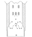
図1〜図7は、本発明による紙幣搬送装置の第1の実施の形態を示す。図1に示すように、本発明の紙幣搬送装置は、搬送通路(2)と、搬送通路(2)内に挿入される紙葉類として紙幣(1)を搬送する搬送装置(3)とを備える。搬送通路(2)は、何れも樹脂製又は金属製の底壁(11)、頂壁(12)及び側壁(13)により形成される。搬送装置(3)は、搬送通路(2)内に回転可能に設けられる摩擦搬送装置(4)と、摩擦搬送装置(4)を回転駆動する駆動装置(5)と、摩擦搬送装置(4)に対して紙幣(1)を押圧する加重装置(7)とを備える。図示の例では、摩擦搬送装置(4)は、搬送ベルトにより構成されるが、搬送ベルトの代わりに、紙幣(1)に接触する搬送ローラを使用してもよい。 FIGS. 1-7 shows 1st Embodiment of the banknote conveying apparatus by this invention. As shown in FIG. 1, the banknote transport apparatus of the present invention includes a transport path (2) and a transport apparatus (3) that transports a banknote (1) as a paper sheet inserted into the transport path (2). Prepare. The transfer passage (2) is formed by a resin or metal bottom wall (11), top wall (12) and side wall (13). The conveying device (3) includes a friction conveying device (4) rotatably provided in the conveying passage (2), a driving device (5) for rotationally driving the friction conveying device (4), and a friction conveying device (4). And a weighting device (7) for pressing the banknote (1). In the illustrated example, the friction conveyance device (4) includes a conveyance belt, but a conveyance roller that contacts the banknote (1) may be used instead of the conveyance belt.
加重装置(7)は、搬送通路(2)に隣接して設けられる保持部(8)と、摩擦搬送装置(4)に接触して自転可能に保持部(8)内に保持されて摩擦搬送装置(4)との間に紙幣(1)を挟持する球体(6)とを備える。図1及び図3に示すように、摩擦搬送装置(4)は、搬送装置(3)の底壁(11)に形成される収容室(14)内に回転可能に軸支される。駆動装置(5)は、所望の減速比を有する動力伝達装置(21)を介して摩擦搬送装置(4)に駆動連結される駆動モータ(20)を有する。動力伝達装置(21)は、歯車列、ベルト伝動装置又はこれらの組み合わせにより構成できる。 The weighting device (7) is held in the holding portion (8) so as to be able to rotate in contact with the holding portion (8) provided adjacent to the transfer passage (2) and the friction transfer device (4), and the friction transfer. A sphere (6) that holds the bill (1) between the device (4) and the device (4). As shown in FIGS. 1 and 3, the friction transfer device (4) is rotatably supported in a storage chamber (14) formed in the bottom wall (11) of the transfer device (3). The drive device (5) has a drive motor (20) that is drivingly connected to the friction transfer device (4) via a power transmission device (21) having a desired reduction ratio. The power transmission device (21) can be constituted by a gear train, a belt transmission device, or a combination thereof.
搬送通路(2)を形成する搬送装置(3)の頂壁(12)には、球体(6)を配置する保持部(8)が設けられる。保持部(8)は、垂直に形成される円筒部(8b)と、円筒部(8b)の底部に形成される内球面(8a)と、搬送通路(2)に連絡して内球面(8a)の下端に形成される開口部(8c)とを有する。球体(6)は、内球面(8a)に接触しかつ内球面(8a)内で全ての方向に自由に転動、摺動又は滑動、即ち自転できると共に、搬送通路(2)から離間する垂直方向に移動することができる。球体(6)に紙幣(1)が接触すると、紙幣(1)の移動方向に依存して、球体(6)が内球面(8a)内で自由に自転するので、摩擦搬送装置(4)と球体(6)との間に挟持される紙幣(1)は、球体(6)との接触面から360度の何れの平面方向にも移動できる。また、球体(6)は、紙幣(1)に接触する全ての球状外面で自重による一定の押圧力で紙幣(1)を摩擦搬送装置(4)に対して押圧する。保持部(8)内で転動し摺動する球体(6)は、摺動に比べて紙幣(1)に対する摩擦力が著しく小さく、下方から球体(6)に外力が加えられると、球体(6)は、保持部(8)内で上方に移動することができる。 On the top wall (12) of the transfer device (3) that forms the transfer path (2), a holding portion (8) for arranging the sphere (6) is provided. The holding portion (8) includes a cylindrical portion (8b) formed vertically, an inner spherical surface (8a) formed at the bottom of the cylindrical portion (8b), and an inner spherical surface (8a) in communication with the conveyance path (2). ) And an opening (8c) formed at the lower end. The sphere (6) is in contact with the inner spherical surface (8a) and can freely roll, slide or slide in all directions within the inner spherical surface (8a), i.e., can rotate, and be separated from the conveyance path (2). Can move in the direction. When the bill (1) comes into contact with the sphere (6), the sphere (6) freely rotates within the inner spherical surface (8a) depending on the moving direction of the bill (1). The banknote (1) sandwiched between the sphere (6) can move in any plane direction of 360 degrees from the contact surface with the sphere (6). In addition, the sphere (6) presses the bill (1) against the friction conveyance device (4) with a constant pressing force by its own weight on all spherical outer surfaces in contact with the bill (1). The sphere (6) that rolls and slides in the holding portion (8) has a significantly smaller frictional force against the banknote (1) than sliding, and when an external force is applied to the sphere (6) from below, the sphere (6 6) can move upward in the holding part (8).
摩擦搬送装置(4)を構成する搬送ベルトは、樹脂材料により形成され、搬送される紙幣及び球体(6)に接触する表面に摩擦係数の大きいゴム材料が使用される。摩擦搬送装置(4)に搬送ローラを使用するとき、搬送ローラの表面に摩擦係数の大きいゴム材料が被覆される。球体(6)は、耐食性のステンレス鋼、鉄若しくは鉄合金又は球体(6)を摩擦搬送装置(4)に向ってばね(15)で押圧する構造では、銅、チタン、アルミニウム等の比較的軽量の金属若しくはこれらの合金又は耐摩耗性の樹脂材料により形成することができる。 The conveying belt constituting the friction conveying device (4) is made of a resin material, and a rubber material having a large coefficient of friction is used on the surface in contact with the conveyed banknote and the sphere (6). When a conveying roller is used in the friction conveying device (4), a rubber material having a large friction coefficient is coated on the surface of the conveying roller. The sphere (6) is a comparatively light weight such as copper, titanium, aluminum, etc. in the structure in which the corrosion-resistant stainless steel, iron or iron alloy or the sphere (6) is pressed by the spring (15) toward the friction transfer device (4). These metals or their alloys or wear-resistant resin materials can be used.
保持部(8)の開口部(8c)の内径は、球体(6)の外径より小さいため、保持部(8)内に収容される球体(6)は、落下せずに、保持部(8)内に保持されるが、保持部(8)内で上方には移動することができる。図4に示すように、球体(6)の底部は、保持部(8)の開口部(8c)を通じて搬送通路(2)内に下方に突出して、搬送通路(2)内に上方に突出する摩擦搬送装置(4)に接触すると共に、搬送通路(2)を通り摩擦搬送装置(4)に接触する紙幣(1)にも接触する。 Since the inner diameter of the opening (8c) of the holding part (8) is smaller than the outer diameter of the sphere (6), the sphere (6) accommodated in the holding part (8) does not fall, and the holding part ( Although it is held in 8), it can move upward in the holding part (8). As shown in FIG. 4, the bottom of the sphere (6) protrudes downward into the transport passage (2) through the opening (8c) of the holding portion (8) and protrudes upward into the transport passage (2). While contacting the friction conveyance device (4), it also contacts the banknote (1) that contacts the friction conveyance device (4) through the conveyance path (2).
搬送通路(2)の入口(16)を形成する側壁(13)には、先細のテーパ面(9)が形成される。搬送通路(2)内に挿入される紙幣(1)を検出する一対の入口センサ(10)は、摩擦搬送装置(4)付近で底壁(11)と頂壁(12)に搬送通路(2)を挟んで設けられる。図示しないが、入口センサ(10)は、搬送通路(2)内を通過する紙幣(1)による光の遮断を検出する発光素子と受光素子とを有するホトカプラにより構成される。入口センサ(10)から照射される光の遮断により紙幣(1)の通過を検出すると、入口センサ(10)は、検出信号を発生し、この検出信号を受信する制御装置(図示せず)駆動装置(5)を作動させるので、摩擦搬送装置(4)が回転される。このとき、球体(6)は、回転する摩擦搬送装置(4)に球面接触して保持部(8)の内球面(8a)内で自転すると共に、搬送通路(2)内に挿入される紙幣(1)に球面接触すれば、球体(6)は、どの平面方向の紙幣(1)の移動にも連動して保持部(8)の内球面(8a)内で自転する。 A tapered surface (9) is formed on the side wall (13) that forms the inlet (16) of the transfer passage (2). A pair of inlet sensors (10) for detecting the banknote (1) inserted into the transport passage (2) is connected to the bottom wall (11) and the top wall (12) near the friction transport device (4). ). Although not shown, the entrance sensor (10) is constituted by a photocoupler having a light emitting element and a light receiving element for detecting light blocking by the banknote (1) passing through the transport passage (2). When the passage of the banknote (1) is detected by blocking the light emitted from the entrance sensor (10), the entrance sensor (10) generates a detection signal and drives a control device (not shown) that receives this detection signal. Since the device (5) is operated, the friction transfer device (4) is rotated. At this time, the sphere (6) comes into spherical contact with the rotating friction conveyance device (4) and rotates in the inner spherical surface (8a) of the holding portion (8), and is inserted into the conveyance passage (2). If spherical contact is made with (1), the sphere (6) rotates within the inner spherical surface (8a) of the holding portion (8) in conjunction with the movement of the bill (1) in any plane direction.
図4に示す実施の形態では、球体(6)は、自重により摩擦搬送装置(4)又は紙幣(1)に接触するが、保持部(8)の内球面(8a)内で球体(6)が自転しても、摩擦搬送装置(4)及び紙幣(1)に対する球体(6)の押圧力は、変化しない。また、自由自転する球体(6)の紙幣(1)に対する摩擦力は、摩擦搬送装置(4)の紙幣(1)に対する摩擦力より小さい。 In the embodiment shown in FIG. 4, the sphere (6) contacts the friction conveyance device (4) or the banknote (1) by its own weight, but the sphere (6) within the inner spherical surface (8a) of the holding portion (8). Even if the ball rotates, the pressing force of the sphere (6) against the friction transfer device (4) and the banknote (1) does not change. Further, the frictional force of the free-rotating sphere (6) on the bill (1) is smaller than the frictional force on the bill (1) of the friction transfer device (4).
搬送通路(2)の長さ方向中心軸に対して紙幣(1)の中心軸が平面上変位し又は傾斜して搬送通路(2)内に紙幣(1)が挿入されると、摩擦搬送装置(4)と球体(6)との間に挟持される紙幣(1)の側縁(1a)は、搬送通路(2)の側壁(13)に当接して、紙幣(1)が弾性変形すると同時に、初期の形状に復帰しようとする復元力が紙幣(1)に発生する。この復元力により、紙幣(1)は、側壁(13)から側縁(1a)を離間させる方向の反力を発生して、搬送通路(2)の中心軸に整合する方向に紙幣(1)が移動する。このとき、紙幣(1)に接触する球体(6)は、紙幣(1)の移動に依存して、どの方向でも保持部(8)内で自転するので、紙幣(1)と球体(6)との摩擦力は小さく、紙幣(1)に発生する反力は、球体(6)との摩擦力より大きい。従って、球体(6)との接触面を含む2次元平面内で反力を解消する方向に移動する紙幣(1)は、自動的に調心され、紙幣(1)の姿勢は、搬送通路(2)の長さ方向中心軸に自動的に整合される。このように、本発明では、搬送通路(2)に紙幣(1)を自動的に調心させる紙幣搬送装置を簡素な構造でかつ安価に製造することができる。 When the bill (1) is inserted into the transport passage (2) when the central axis of the bill (1) is displaced or inclined on the plane with respect to the longitudinal center axis of the transport passage (2), the friction transport device When the side edge (1a) of the banknote (1) sandwiched between (4) and the sphere (6) is in contact with the side wall (13) of the transport passage (2), the banknote (1) is elastically deformed. At the same time, a restoring force is generated on the bill (1) to return to the initial shape. With this restoring force, the banknote (1) generates a reaction force in the direction of separating the side edge (1a) from the side wall (13), and the banknote (1) in a direction aligned with the central axis of the transport path (2). Move. At this time, the sphere (6) in contact with the banknote (1) rotates in the holding section (8) in any direction depending on the movement of the banknote (1), so the banknote (1) and the sphere (6) The reaction force generated on the banknote (1) is larger than the friction force on the sphere (6). Accordingly, the bill (1) moving in the direction to cancel the reaction force in the two-dimensional plane including the contact surface with the sphere (6) is automatically aligned, and the posture of the bill (1) 2) Automatically aligned with the longitudinal center axis. As described above, according to the present invention, it is possible to manufacture a banknote transport apparatus that automatically aligns the banknote (1) in the transport path (2) with a simple structure and at a low cost.
図7は、搬送装置(3)の頂壁(12)に摩擦搬送装置(4)を回転可能に取付け、搬送装置(3)の底壁(11)に保持部(8)を設け、保持部(8)内に球体(6)を配置して、弾性体であるばね(15)の弾性力により球体(6)を摩擦搬送装置(4)に押圧して、摩擦搬送装置(4)と球体(6)との間を通過する紙幣(1)に球体(6)を接触させて、球体(6)と摩擦搬送装置(4)とを上下逆転して配置する図4の変形例を示す。図7に示す実施の形態では、摩擦搬送装置(4)の下方に配置される球体(6)の自重が紙幣(1)に作用しないので、所定の弾性力を発生するばね(15)により球体(6)を上方に押圧することができるが、球体(6)に下方への外力が加えられると、ばね(15)の弾力に抗して球体(6)は、上方に移動できる。この実施の形態でも、球体(6)は、紙幣(1)に接触する全ての球状外面で一定の押圧力で紙幣(1)を摩擦搬送装置(4)に対して押圧し、球体(6)の作用効果は、図1〜図6に示すものと同等である。 FIG. 7 shows that the friction transfer device (4) is rotatably attached to the top wall (12) of the transfer device (3), and a holding portion (8) is provided on the bottom wall (11) of the transfer device (3). (8) The spherical body (6) is disposed inside, and the spherical body (6) is pressed against the frictional conveying device (4) by the elastic force of the spring (15), which is an elastic body. 4 shows a modification of FIG. 4 in which a sphere (6) is brought into contact with a bill (1) passing between (6) and the sphere (6) and the friction transfer device (4) are arranged upside down. In the embodiment shown in FIG. 7, since the dead weight of the sphere (6) arranged below the friction transfer device (4) does not act on the bill (1), the sphere is formed by the spring (15) that generates a predetermined elastic force. (6) can be pressed upward, but when a downward external force is applied to the sphere (6), the sphere (6) can move upward against the elasticity of the spring (15). Also in this embodiment, the sphere (6) presses the bill (1) against the friction transfer device (4) with a constant pressing force on all spherical outer surfaces that contact the bill (1), and the sphere (6) The effect of is the same as that shown in FIGS.
図8〜図16は、図1〜図7に示す実施の形態の搬送通路(2)の両側壁に2対のガイドローラ(22)を対向して回転可能に取り付けた第2の実施の形態を示す。第2の実施の形態では、紙幣(1)の縁部が嵌合されるV字状又はU字状の環状溝(23)が各ガイドローラ(22)の外周部に形成され、搬送通路(2)の側壁(13)は、湾曲形状に形成される。 FIGS. 8 to 16 show a second embodiment in which two pairs of guide rollers (22) are rotatably attached to both side walls of the conveyance path (2) of the embodiment shown in FIGS. Indicates. In the second embodiment, a V-shaped or U-shaped annular groove (23) into which the edge of the banknote (1) is fitted is formed on the outer periphery of each guide roller (22), The side wall (13) of 2) is formed in a curved shape.
図11〜図16に示すように、搬送通路(2)の長さ方向中心軸に対して紙幣(1)の中心軸が変位して搬送通路(2)内に紙幣(1)が挿入されるとき、紙幣(1)の側縁は、ガイドローラ(22)に接触し、各ガイドローラ(22)は、紙幣(1)との接触により回転しながら、搬送通路(2)に整合するように紙幣(1)の搬送方向を円滑に修正するので、最終的に紙幣(1)は、図15及び図16に示すように、搬送通路(2)に対して容易に調心され、同軸上に配置されて搬送される。 As shown in FIGS. 11 to 16, the central axis of the banknote (1) is displaced with respect to the central axis in the length direction of the transport path (2), and the banknote (1) is inserted into the transport path (2). When the side edge of the banknote (1) is in contact with the guide roller (22), each guide roller (22) is aligned with the transport path (2) while rotating by contact with the banknote (1). Since the conveyance direction of the banknote (1) is smoothly corrected, the banknote (1) is finally easily aligned with the conveyance path (2) as shown in FIG. 15 and FIG. Arranged and transported.
本発明は、搬送通路に整合させて紙葉類を搬送する種々の搬送装置に適用することができる。 The present invention can be applied to various transport devices that transport paper sheets in alignment with a transport path.
(1)・・紙幣(紙葉類)、 (1a)・・側縁、 (2)・・搬送通路、 (3)・・搬送装置、 (4)・・摩擦搬送装置、 (5)・・駆動装置、 (6)・・球体、 (7)・・加重装置、 (8)・・保持部、 (8a)・・内球面、 (8b)・・円筒部、 (8c)・・開口部、 (9)・・テーパ面、 (10)・・入口センサ、 (11)・・底壁、 (12)・・頂壁、 (13)・・側壁、 (14)・・収容室、 (15)・・ばね、 (16)・・入口、 (20)・・駆動モータ、 (21)・・動力伝達装置、 (22)・・ガイドローラ、 (23)・・環状溝、 (1) ・ ・ Bills (paper sheets), (1a) ・ ・ Side edges, (2) ・ ・ Conveying passageway, (3) ・ ・ Conveying device, (4) ・ ・ Friction conveying device, (5) ・ ・(6) ·· Sphere, (7) · · Weighting device, (8) · · Holding part, (8a) · · Inner spherical surface, (8b) · · Cylindrical part, (8c) · · Opening part, (9) ・ ・ Taper surface, (10) ・ ・ Inlet sensor, (11) ・ ・ Bottom wall, (12) ・ ・ Top wall, (13) ・ ・ Side wall, (14) ・ ・ Containment chamber, (15)・ ・ Spring, (16) ・ ・ Inlet, (20) ・ ・ Drive motor, (21) ・ ・ Power transmission device, (22) ・ ・ Guide roller, (23) ・ ・ Annular groove,
Claims (17)
搬送通路に沿って紙葉類を搬送する搬送装置とを備え、
搬送装置は、搬送通路内に回転可能に設けられる摩擦搬送装置と、摩擦搬送装置を回転駆動する駆動装置と、摩擦搬送装置に対して紙葉類を押圧する加重装置とを備え、
加重装置は、搬送通路に隣接して設けられる保持部と、摩擦搬送装置に接触して自転可能に保持部内に保持されて摩擦搬送装置との間に紙葉類を挟持する球体とを備えることを特徴とする紙葉類搬送装置。 A conveyance path;
A transport device that transports paper sheets along the transport path,
The conveying device includes a friction conveying device rotatably provided in the conveying path, a driving device that rotationally drives the friction conveying device, and a weighting device that presses the paper sheet against the friction conveying device,
The weighting device includes a holding unit provided adjacent to the conveyance path, and a sphere that is held in the holding unit so as to rotate in contact with the friction conveyance device and sandwich the paper sheet between the friction conveyance device. Paper sheet conveying device characterized by the above.
搬送通路の頂壁に設けた保持部内に球体を配置した請求項1〜10の何れか1項に記載の紙葉類搬送装置。 A friction transfer device is rotatably arranged in a storage chamber formed on the bottom wall of the transfer passage,
The paper sheet transport apparatus according to any one of claims 1 to 10, wherein a spherical body is disposed in a holding portion provided on a top wall of the transport path.
搬送通路の底壁に設けた保持部内に球体を配置した請求項1〜10の何れか1項に記載の紙葉類搬送装置。 A friction transfer device is rotatably mounted in a storage chamber formed on the top wall of the transfer passage,
The paper sheet transport apparatus according to any one of claims 1 to 10, wherein a spherical body is disposed in a holding portion provided on a bottom wall of the transport path.
Priority Applications (10)
| Application Number | Priority Date | Filing Date | Title |
|---|---|---|---|
| JP2010129462A JP2011255976A (en) | 2010-06-04 | 2010-06-04 | Paper sheet carrying device |
| CN2011800359803A CN103025635A (en) | 2010-06-04 | 2011-05-18 | Document transporter |
| BR112012030945A BR112012030945A2 (en) | 2010-06-04 | 2011-05-18 | document carrier |
| EP11789399.0A EP2576404A4 (en) | 2010-06-04 | 2011-05-18 | Document transporter |
| PCT/JP2011/002767 WO2011151984A1 (en) | 2010-06-04 | 2011-05-18 | Document transporter |
| MX2012014157A MX2012014157A (en) | 2010-06-04 | 2011-05-18 | Document transporter. |
| AU2011262134A AU2011262134A1 (en) | 2010-06-04 | 2011-05-18 | Document transporter |
| CA2801628A CA2801628A1 (en) | 2010-06-04 | 2011-05-18 | Document transporter |
| TW100118119A TW201210928A (en) | 2010-06-04 | 2011-05-24 | Document transporter |
| ZA2012/09451A ZA201209451B (en) | 2010-06-04 | 2012-12-12 | Document transporter |
Applications Claiming Priority (1)
| Application Number | Priority Date | Filing Date | Title |
|---|---|---|---|
| JP2010129462A JP2011255976A (en) | 2010-06-04 | 2010-06-04 | Paper sheet carrying device |
Publications (2)
| Publication Number | Publication Date |
|---|---|
| JP2011255976A true JP2011255976A (en) | 2011-12-22 |
| JP2011255976A5 JP2011255976A5 (en) | 2013-07-11 |
Family
ID=45066377
Family Applications (1)
| Application Number | Title | Priority Date | Filing Date |
|---|---|---|---|
| JP2010129462A Pending JP2011255976A (en) | 2010-06-04 | 2010-06-04 | Paper sheet carrying device |
Country Status (10)
| Country | Link |
|---|---|
| EP (1) | EP2576404A4 (en) |
| JP (1) | JP2011255976A (en) |
| CN (1) | CN103025635A (en) |
| AU (1) | AU2011262134A1 (en) |
| BR (1) | BR112012030945A2 (en) |
| CA (1) | CA2801628A1 (en) |
| MX (1) | MX2012014157A (en) |
| TW (1) | TW201210928A (en) |
| WO (1) | WO2011151984A1 (en) |
| ZA (1) | ZA201209451B (en) |
Cited By (7)
| Publication number | Priority date | Publication date | Assignee | Title |
|---|---|---|---|---|
| JP2016069118A (en) * | 2014-09-29 | 2016-05-09 | 富士通フロンテック株式会社 | Bankbook conveyance equipment and bankbook printer |
| JP2016071443A (en) * | 2014-09-26 | 2016-05-09 | 富士通フロンテック株式会社 | Passbook carrier device and passbook printer |
| JP2016185872A (en) * | 2015-03-27 | 2016-10-27 | 富士ゼロックス株式会社 | Sheet conveyance device and image forming apparatus |
| JP2016185850A (en) * | 2015-03-27 | 2016-10-27 | 富士ゼロックス株式会社 | Paper conveyance device and image forming apparatus |
| JP2017075049A (en) * | 2015-10-15 | 2017-04-20 | ケイディケイ株式会社 | Sheet delivery direction control mechanism |
| WO2019030998A1 (en) | 2017-08-08 | 2019-02-14 | 日本金銭機械株式会社 | Friction transport device and paper sheet transport device |
| JP2021012559A (en) * | 2019-07-08 | 2021-02-04 | グローリー株式会社 | Paper sheet take-in mechanism and paper sheet processing device |
Families Citing this family (4)
| Publication number | Priority date | Publication date | Assignee | Title |
|---|---|---|---|---|
| CN103302962B (en) * | 2013-07-02 | 2015-03-25 | 青岛海刚烫印设备制造有限公司 | Automatic note gilding press |
| US9760050B2 (en) * | 2015-03-27 | 2017-09-12 | Fuji Xerox Co., Ltd. | Sheet conveying device and image forming apparatus |
| DE102017105842B4 (en) * | 2017-03-17 | 2019-05-29 | Wincor Nixdorf International Gmbh | Device for aligning notes of value |
| CN111775554A (en) * | 2020-06-08 | 2020-10-16 | 安徽兴中新材料股份有限公司 | Printing device for plastic packaging bag |
Citations (6)
| Publication number | Priority date | Publication date | Assignee | Title |
|---|---|---|---|---|
| JPS57165634U (en) * | 1981-04-08 | 1982-10-19 | ||
| JPS5988047U (en) * | 1982-12-03 | 1984-06-14 | 株式会社リコー | Copy paper guide device |
| EP0300095A1 (en) * | 1987-07-20 | 1989-01-25 | Agfa-Gevaert N.V. | An electrophotographic printer with angular sheet alignment |
| JPH07187454A (en) * | 1993-11-15 | 1995-07-25 | At & T Global Inf Solutions Internatl Inc | Document collating system |
| JPH11322134A (en) * | 1998-05-15 | 1999-11-24 | Glory Ltd | Sheet carrier device |
| JP2007314344A (en) * | 2006-05-25 | 2007-12-06 | K D K Kk | Paper conveyance means and laminator using it |
Family Cites Families (7)
| Publication number | Priority date | Publication date | Assignee | Title |
|---|---|---|---|---|
| JPS5148317Y1 (en) * | 1970-08-14 | 1976-11-20 | ||
| WO1980002336A1 (en) * | 1979-04-20 | 1980-10-30 | Canon Kk | Text orientating device |
| JPH08108954A (en) * | 1994-10-07 | 1996-04-30 | Omron Corp | Paper sheet posture control mechanism, paper sheet carrying device using this paper sheet posture control mechanism and paper sheet processing device |
| IT1291189B1 (en) * | 1997-03-12 | 1998-12-29 | Gera Srl | DEVICE FOR FEEDING SHEETS TO A FOLDING MACHINE. |
| US6102391A (en) * | 1998-05-15 | 2000-08-15 | Pitney Bowes Inc. | Right angle transfer apparatus |
| US6712356B2 (en) * | 2000-02-09 | 2004-03-30 | Mars Incorporated | Self aligning transport mechanism for media of variable media widths |
| CA2323329C (en) * | 2000-10-17 | 2009-12-29 | Cashcode Company Inc. | Banknote drive rollers with antijamming characteristics |
-
2010
- 2010-06-04 JP JP2010129462A patent/JP2011255976A/en active Pending
-
2011
- 2011-05-18 BR BR112012030945A patent/BR112012030945A2/en not_active IP Right Cessation
- 2011-05-18 MX MX2012014157A patent/MX2012014157A/en not_active Application Discontinuation
- 2011-05-18 AU AU2011262134A patent/AU2011262134A1/en not_active Abandoned
- 2011-05-18 CN CN2011800359803A patent/CN103025635A/en active Pending
- 2011-05-18 EP EP11789399.0A patent/EP2576404A4/en not_active Withdrawn
- 2011-05-18 CA CA2801628A patent/CA2801628A1/en not_active Abandoned
- 2011-05-18 WO PCT/JP2011/002767 patent/WO2011151984A1/en active Application Filing
- 2011-05-24 TW TW100118119A patent/TW201210928A/en unknown
-
2012
- 2012-12-12 ZA ZA2012/09451A patent/ZA201209451B/en unknown
Patent Citations (6)
| Publication number | Priority date | Publication date | Assignee | Title |
|---|---|---|---|---|
| JPS57165634U (en) * | 1981-04-08 | 1982-10-19 | ||
| JPS5988047U (en) * | 1982-12-03 | 1984-06-14 | 株式会社リコー | Copy paper guide device |
| EP0300095A1 (en) * | 1987-07-20 | 1989-01-25 | Agfa-Gevaert N.V. | An electrophotographic printer with angular sheet alignment |
| JPH07187454A (en) * | 1993-11-15 | 1995-07-25 | At & T Global Inf Solutions Internatl Inc | Document collating system |
| JPH11322134A (en) * | 1998-05-15 | 1999-11-24 | Glory Ltd | Sheet carrier device |
| JP2007314344A (en) * | 2006-05-25 | 2007-12-06 | K D K Kk | Paper conveyance means and laminator using it |
Cited By (8)
| Publication number | Priority date | Publication date | Assignee | Title |
|---|---|---|---|---|
| JP2016071443A (en) * | 2014-09-26 | 2016-05-09 | 富士通フロンテック株式会社 | Passbook carrier device and passbook printer |
| JP2016069118A (en) * | 2014-09-29 | 2016-05-09 | 富士通フロンテック株式会社 | Bankbook conveyance equipment and bankbook printer |
| JP2016185872A (en) * | 2015-03-27 | 2016-10-27 | 富士ゼロックス株式会社 | Sheet conveyance device and image forming apparatus |
| JP2016185850A (en) * | 2015-03-27 | 2016-10-27 | 富士ゼロックス株式会社 | Paper conveyance device and image forming apparatus |
| JP2017075049A (en) * | 2015-10-15 | 2017-04-20 | ケイディケイ株式会社 | Sheet delivery direction control mechanism |
| WO2019030998A1 (en) | 2017-08-08 | 2019-02-14 | 日本金銭機械株式会社 | Friction transport device and paper sheet transport device |
| US11136210B2 (en) | 2017-08-08 | 2021-10-05 | Japan Cash Machine Co., Ltd. | Friction transport device and paper sheet transport device |
| JP2021012559A (en) * | 2019-07-08 | 2021-02-04 | グローリー株式会社 | Paper sheet take-in mechanism and paper sheet processing device |
Also Published As
| Publication number | Publication date |
|---|---|
| WO2011151984A1 (en) | 2011-12-08 |
| AU2011262134A1 (en) | 2013-01-24 |
| BR112012030945A2 (en) | 2016-11-01 |
| CA2801628A1 (en) | 2011-12-08 |
| EP2576404A4 (en) | 2014-01-22 |
| ZA201209451B (en) | 2013-08-28 |
| MX2012014157A (en) | 2013-05-01 |
| EP2576404A1 (en) | 2013-04-10 |
| CN103025635A (en) | 2013-04-03 |
| TW201210928A (en) | 2012-03-16 |
Similar Documents
| Publication | Publication Date | Title |
|---|---|---|
| JP2011255976A (en) | Paper sheet carrying device | |
| JP4700978B2 (en) | Identification device and roller | |
| EP2301869B1 (en) | Paper sheet pick up device | |
| EP2955134A1 (en) | Medium separation device of atm | |
| JP2011255976A5 (en) | ||
| JP4698574B2 (en) | Paper sheet separation mechanism | |
| WO2012017785A1 (en) | Media multi-feed prevention mechanism and media delivery device | |
| JP2005255409A (en) | Paper sheet delivery device | |
| JP6971862B2 (en) | Paper leaf handling device, automated teller machine and paper leaf handling method | |
| KR20090015466A (en) | Media skew adjusting apparatus for media dispenser | |
| WO2013014697A1 (en) | Paper pay-out device and paper processing device | |
| AU765785B2 (en) | Document dispensing apparatus | |
| JP5546261B2 (en) | Media handling device | |
| KR20110110498A (en) | Medium separating apparatus for automatic teller machine | |
| US20110298172A1 (en) | Document conveyor | |
| JP5608814B2 (en) | Paper sheet identification device | |
| US9472041B2 (en) | Clamping of media items | |
| KR20130075913A (en) | Roller and two paper detecting device having the same | |
| KR102177762B1 (en) | Medium transfering apparatus of automatic teller machine | |
| KR100777574B1 (en) | Device for sensing overlap of paper money | |
| KR20170098457A (en) | Bill handling machine | |
| KR20160125941A (en) | Paper currency identifying device | |
| KR101120918B1 (en) | Medium separating apparatus for automatic teller machine | |
| KR20110092499A (en) | Automatic teller machine | |
| KR20110008448U (en) | Joint Structure of Shaft and Gear |
Legal Events
| Date | Code | Title | Description |
|---|---|---|---|
| A521 | Written amendment |
Free format text: JAPANESE INTERMEDIATE CODE: A523 Effective date: 20130528 |
|
| A621 | Written request for application examination |
Free format text: JAPANESE INTERMEDIATE CODE: A621 Effective date: 20130528 |
|
| A131 | Notification of reasons for refusal |
Free format text: JAPANESE INTERMEDIATE CODE: A131 Effective date: 20140304 |
|
| A02 | Decision of refusal |
Free format text: JAPANESE INTERMEDIATE CODE: A02 Effective date: 20140716 |