JP2011125123A - Server uninterruptible power supply - Google Patents
Server uninterruptible power supply Download PDFInfo
- Publication number
- JP2011125123A JP2011125123A JP2009279900A JP2009279900A JP2011125123A JP 2011125123 A JP2011125123 A JP 2011125123A JP 2009279900 A JP2009279900 A JP 2009279900A JP 2009279900 A JP2009279900 A JP 2009279900A JP 2011125123 A JP2011125123 A JP 2011125123A
- Authority
- JP
- Japan
- Prior art keywords
- server
- power supply
- converter
- power
- secondary battery
- Prior art date
- Legal status (The legal status is an assumption and is not a legal conclusion. Google has not performed a legal analysis and makes no representation as to the accuracy of the status listed.)
- Granted
Links
Images







Classifications
-
- H—ELECTRICITY
- H02—GENERATION; CONVERSION OR DISTRIBUTION OF ELECTRIC POWER
- H02J—ELECTRIC POWER NETWORKS; CIRCUIT ARRANGEMENTS OR SYSTEMS FOR SUPPLYING OR DISTRIBUTING ELECTRIC POWER; SYSTEMS FOR STORING ELECTRIC ENERGY
- H02J9/00—Circuit arrangements for emergency or stand-by power supply, e.g. for emergency lighting
- H02J9/04—Circuit arrangements for emergency or stand-by power supply, e.g. for emergency lighting in which the distribution system is disconnected from the normal source and connected to a standby source
- H02J9/06—Circuit arrangements for emergency or stand-by power supply, e.g. for emergency lighting in which the distribution system is disconnected from the normal source and connected to a standby source with automatic change-over, e.g. UPS systems
- H02J9/061—Circuit arrangements for emergency or stand-by power supply, e.g. for emergency lighting in which the distribution system is disconnected from the normal source and connected to a standby source with automatic change-over, e.g. UPS systems for DC powered loads
-
- G—PHYSICS
- G06—COMPUTING OR CALCULATING; COUNTING
- G06F—ELECTRIC DIGITAL DATA PROCESSING
- G06F1/00—Details not covered by groups G06F3/00 - G06F13/00 and G06F21/00
- G06F1/26—Power supply means, e.g. regulation thereof
- G06F1/30—Means for acting in the event of power-supply failure or interruption, e.g. power-supply fluctuations
-
- G—PHYSICS
- G06—COMPUTING OR CALCULATING; COUNTING
- G06F—ELECTRIC DIGITAL DATA PROCESSING
- G06F11/00—Error detection; Error correction; Monitoring
- G06F11/07—Responding to the occurrence of a fault, e.g. fault tolerance
- G06F11/16—Error detection or correction of the data by redundancy in hardware
- G06F11/20—Error detection or correction of the data by redundancy in hardware using active fault-masking, e.g. by switching out faulty elements or by switching in spare elements
- G06F11/2015—Redundant power supplies
-
- H—ELECTRICITY
- H02—GENERATION; CONVERSION OR DISTRIBUTION OF ELECTRIC POWER
- H02J—ELECTRIC POWER NETWORKS; CIRCUIT ARRANGEMENTS OR SYSTEMS FOR SUPPLYING OR DISTRIBUTING ELECTRIC POWER; SYSTEMS FOR STORING ELECTRIC ENERGY
- H02J7/00—Circuit arrangements for charging or discharging batteries or for supplying loads from batteries
Landscapes
- Engineering & Computer Science (AREA)
- Theoretical Computer Science (AREA)
- Physics & Mathematics (AREA)
- General Engineering & Computer Science (AREA)
- General Physics & Mathematics (AREA)
- Business, Economics & Management (AREA)
- Emergency Management (AREA)
- Power Engineering (AREA)
- Quality & Reliability (AREA)
- Stand-By Power Supply Arrangements (AREA)
- Charge And Discharge Circuits For Batteries Or The Like (AREA)
- Secondary Cells (AREA)
Abstract
【課題】サーバーのサーバーケースに収納しながら、停電時においてサーバーを安定に動作する。二次電池から電力を供給する電源ラインの配線を簡単にする。
【解決手段】サーバーの無停電電源装置は、サーバー90のサーバーケース91に収納されて、サーバー90の直流12Vの電源ライン43に接続される。この無停電電源装置は、電源ライン43の電圧を二次電池1の充電電圧に昇圧する昇圧用のDC/DCコンバータ3と、定格電圧を13V以上であって60V以下とする二次電池1と、二次電池1の電圧を電源ライン43の電圧に降圧して出力する降圧用のDC/DCコンバータ2と、昇圧用のDC/DCコンバータ3と降圧用のDC/DCコンバータ2とを制御する充放電制御回路4とを備えている。無停電電源装置は、商用電源95の停電状態において、二次電池1の出力電圧を電源ライン43の電圧に降圧して出力して、サーバー90を動作状態を保持する。
【選択図】図3The server operates stably in the event of a power failure while being stored in the server case of the server. Simplify the wiring of the power supply line that supplies power from the secondary battery.
A server uninterruptible power supply is housed in a server case 91 of a server 90 and connected to a DC 12V power line 43 of the server 90. This uninterruptible power supply includes a boosting DC / DC converter 3 that boosts the voltage of the power supply line 43 to the charging voltage of the secondary battery 1, and the secondary battery 1 that has a rated voltage of 13V or more and 60V or less. The step-down DC / DC converter 2 that steps down the voltage of the secondary battery 1 to the voltage of the power supply line 43 and outputs the voltage, the step-up DC / DC converter 3 and the step-down DC / DC converter 2 are controlled. And a charge / discharge control circuit 4. The uninterruptible power supply apparatus lowers the output voltage of the secondary battery 1 to the voltage of the power supply line 43 and outputs it in the power failure state of the commercial power supply 95 to keep the server 90 operating.
[Selection] Figure 3
Description
本発明は、サーバーのサーバーケースに収納されて、停電時には所定の時間サーバーに電力を供給するサーバーの無停電電源装置に関する。 The present invention relates to an uninterruptible power supply for a server that is housed in a server case of a server and supplies power to the server for a predetermined time during a power failure.
サーバーは、停電時に正常な動作を保証する必要がある。このことを実現するために、サーバーの外部に設置される無停電電源装置が開発されている(特許文献1参照)。この無停電電源装置は、鉛蓄電池などの二次電池を内蔵し、停電時には交流の商用電源に代わってサーバーに交流電力を供給する。したがって、この無停電電源装置は、サーバーの商用電源の入力側に接続されて、停電時に商用電源に変わって交流電力を出力する。このため、この無停電電源装置は、停電を検出すると二次電池の出力をDC/ACインバータで商用電源と同じ電圧の交流に変換して出力する。停電時には、二次電池から出力される電力は、DC/ACインバータで交流に変換してサーバーに供給され、さらに、サーバーに内蔵される電源回路でもって、入力される交流を所定の電圧の直流に変換して電源ラインに供給している。この回路構成によると、二次電池の出力は、DC/ACインバータと電源回路を介して電源ラインに供給されるので、二次電池から出力される電力の利用効率が相当に低くなる欠点がある。さらに、この無停電電源装置は、サーバーケースの外部に設置されるので、便利に使用できない欠点もある。 The server needs to ensure normal operation during a power failure. In order to realize this, an uninterruptible power supply device installed outside the server has been developed (see Patent Document 1). This uninterruptible power supply incorporates a secondary battery such as a lead-acid battery, and supplies AC power to the server instead of an AC commercial power supply in the event of a power failure. Therefore, this uninterruptible power supply is connected to the input side of the commercial power supply of the server, and changes to the commercial power supply and outputs AC power in the event of a power failure. For this reason, when this uninterruptible power supply detects a power failure, the output of the secondary battery is converted into an alternating current having the same voltage as that of the commercial power source by the DC / AC inverter and output. In the event of a power failure, the power output from the secondary battery is converted into alternating current by a DC / AC inverter and supplied to the server. Further, the input alternating current is converted into direct current of a predetermined voltage by a power circuit built in the server. It is converted to and supplied to the power line. According to this circuit configuration, since the output of the secondary battery is supplied to the power supply line via the DC / AC inverter and the power supply circuit, there is a disadvantage that the utilization efficiency of the power output from the secondary battery is considerably reduced. . Furthermore, since the uninterruptible power supply is installed outside the server case, there is a disadvantage that it cannot be used conveniently.
以上の欠点を解消するために、サーバーのサーバーケースの底部にセットできる無停電電源装置が開発されている(特許文献2参照)。 In order to eliminate the above drawbacks, an uninterruptible power supply that can be set at the bottom of a server case of a server has been developed (see Patent Document 2).
特許文献2の無停電電源装置は、内蔵する電池に充電される電力を交流に変換することなく、DC/DCコンバータで電源ラインの直流電圧に変換して出力する。したがって、DC/DCコンバータの出力を直接にサーバーの電源ラインに供給して電池の利用効率を高くできる。この無停電電源装置は、サーバーの電源ラインの電圧よりも低い電圧の二次電池を備えるので、停電時には二次電池の電圧を昇圧用のDC/DCコンバータで昇圧してサーバーの電源ラインに供給する必要がある。この回路構成によると、二次電池の電力効率が低下するばかりでなく、二次電池の放電電流が大きくなることから、放電ラインの電気抵抗を低抵抗な状態とする必要があって、電力を供給するラインを極めて太い配線とする必要があるなどの弊害が発生する。とくに、サーバーケースに収納される無停電電源装置は、電力効率をいかに高くできるかが極めて大切である。それは、二次電池の電力を効率よくサーバーに供給して、サーバーの動作時間を長くできることに加えて、停電時に発生する無停電電源装置の発熱を少なくできるからである。停電時における無停電電源装置の発熱は決して無視できない。たとえば、電力効率を90%とする無停電電源装置が1kWの電力を供給するとき、100Wの電力が発熱に利用されて温度を上昇させる。さらに、停電時にはエアコンの動作が停止することから、サーバーと無停電電源装置の両方の発熱を有効に冷却できない状態となる。この状態で、サーバーを正常に動作させるために、無停電電源装置の発熱は極力少なくすることが要求される。とくに、サーバーケースに収納している無停電電源装置の発熱が大きくなると、これがサーバーを加熱してサーバーの安定な動作を保証できなくする。
The uninterruptible power supply of
本発明は、以上の欠点を解決することを目的に開発されたもので、本発明の重要な目的は、サーバーのサーバーケースに収納しながら、停電時においてサーバーを安定に動作できるサーバーの無停電電源装置を提供することにある。
また、本発明の他の大切な目的は、二次電池から電力を供給する電源ラインの配線を簡単にしながら、二次電池から効率よくサーバーの電源ラインに電力を供給できるサーバーの無停電電源装置を提供することにある。
さらにまた、本発明の他の大切な目的は、サーバーのサーバーケースに収納することで、便利に使用できるサーバーの無停電電源装置を提供することにある。
The present invention was developed for the purpose of solving the above drawbacks, and an important object of the present invention is to provide a server uninterruptible power supply that can stably operate the server during a power failure while being housed in the server case of the server. It is to provide a power supply device.
Another important object of the present invention is to provide an uninterruptible power supply for a server that can efficiently supply power from the secondary battery to the server power line while simplifying the wiring of the power line that supplies power from the secondary battery. Is to provide.
Furthermore, another important object of the present invention is to provide an uninterruptible power supply for a server that can be conveniently used by being housed in a server case of the server.
本発明のサーバーの無停電電源装置は、サーバー90のサーバーケース91に収納され、かつサーバー90の直流12Vの電源ライン43にDC/DCコンバータを介して接続されて、電源ライン43の電力で充電され、かつ電源ライン43に電力を供給する二次電池1を備えている。この無停電電源装置は、サーバー90の電源ライン43に接続されて電源ライン43の電圧を二次電池1の充電電圧に昇圧する昇圧用のDC/DCコンバータ3と、この昇圧用のDC/DCコンバータ3で充電される定格電圧を13V以上であって60V以下とする二次電池1と、この二次電池1の電圧を電源ライン43の電圧に降圧してサーバー90の電源ライン43に出力する降圧用のDC/DCコンバータ2と、昇圧用のDC/DCコンバータ3と降圧用のDC/DCコンバータ2とを制御する充放電制御回路4とを備えている。無停電電源装置は、サーバー90に電力を供給する商用電源95の停電状態において、二次電池1の出力電圧が、降圧用のDC/DCコンバータ2でもって、サーバー90の電源ライン43の電圧に降圧して電源ライン43に出力されて、サーバー90を動作状態を保持する。
The server uninterruptible power supply of the present invention is housed in the
以上の無停電電源装置は、サーバーのサーバーケースに収納して便利に使用できるにもかかわらず、停電時においてはサーバーを安定に動作状態にできる特徴がある。それは、二次電池の電圧をサーバーの電源ラインの12Vよりも高くして、停電時には二次電池の電圧を降圧用のDC/DCコンバータで降圧して、サーバーの電源ラインに供給するからである。降圧用のDC/DCコンバータは、二次電池から電源ラインに電力を供給する状態と、電力の供給を遮断する状態とを所定の周期で繰り返すことで、すなわち、二次電池と電源ラインとの間に接続しているスイッチング素子を所定の周期でオンオフに切り換えるデューティーをコントロールすることで、電源ラインに電力を供給できる。この状態で電力を供給する降圧用のDC/DCコンバータは、スイッチング素子をオンに切り換える状態で効率よく二次電池の電力を電源ラインに供給し、またスイッチング素子をオフに切り換えるタイミングで平均的に供給する電力をコントロールするので、二次電池から電源ラインに極めて効率よく電力を供給できる。すなわち、スイッチング素子をオンに切り換えるタイミングで、二次電池から電源ラインに供給されるときに発生する電力ロスは、スイッチング素子のオン抵抗のみであるから、スイッチング素子にオン抵抗の小さい素子を使用することで、二次電池から電源ラインに供給される電力ロスを極めて小さくできる。これに対して、昇圧用のDC/DCコンバータは、二次電池から出力される電力をコイルに蓄え、あるいはトランスで昇圧して電源ラインに供給する必要がある。コイルに電力を蓄えて昇圧する回路構成にあっては、コイルに通電するタイミングでの電力ロスを0にできず、また、トランスで昇圧する回路構成にあっては、トランスの効率を100%にできず、これ等が電力効率を低くする原因となる。 Although the above uninterruptible power supply can be conveniently used by being housed in the server case of the server, it has a feature that allows the server to be stably operated during a power failure. This is because the voltage of the secondary battery is made higher than 12V of the server power line, and the voltage of the secondary battery is stepped down by a step-down DC / DC converter and supplied to the server power line in the event of a power failure. . The step-down DC / DC converter repeats a state in which power is supplied from the secondary battery to the power supply line and a state in which the supply of power is cut off in a predetermined cycle, that is, between the secondary battery and the power supply line. Electric power can be supplied to the power supply line by controlling the duty of switching on and off the switching elements connected between them in a predetermined cycle. The step-down DC / DC converter that supplies power in this state efficiently supplies the power of the secondary battery to the power supply line in a state where the switching element is turned on, and on average at the timing when the switching element is turned off. Since the power to be supplied is controlled, the power can be supplied from the secondary battery to the power supply line very efficiently. In other words, the power loss that occurs when the switching element is turned on at the time when it is supplied from the secondary battery to the power supply line is only the on-resistance of the switching element. Therefore, an element having a low on-resistance is used as the switching element. Thus, the power loss supplied from the secondary battery to the power supply line can be extremely reduced. In contrast, a DC / DC converter for boosting needs to store electric power output from a secondary battery in a coil, or boost it with a transformer and supply it to a power supply line. In the circuit configuration in which power is stored in the coil and boosted, the power loss at the timing when the coil is energized cannot be reduced to 0. In the circuit configuration in which the voltage is boosted by the transformer, the efficiency of the transformer is set to 100%. This cannot be done, and this causes a reduction in power efficiency.
降圧用のDC/DCコンバータは、極めて簡単な回路構成としながら、極めて効率よく二次電池の電力をサーバーの電源ラインに供給して電力効率を極めて高くできる。電力効率は、無停電電源装置が動作する状態での発熱量を特定する。電力効率を90%とする無停電電源装置は、二次電池から出力される電力の10%を発熱として温度を上昇させる。すなわち、電源ラインに供給されないで損失となる電力は、無停電電源装置を発熱させる電力に利用される。以上の無停電電源装置は、電力効率を極めて高くできることから、停電して二次電池からサーバーの電源ラインに電力を供給する状態での発熱量を少なくできる。このため、停電時にそれ自体でも発熱するサーバーを、無停電電源装置で加熱する熱エネルギを少なくして、サーバーを安定に動作できる。 The step-down DC / DC converter has a very simple circuit configuration, and can very efficiently supply power of the secondary battery to the power line of the server to achieve extremely high power efficiency. The power efficiency specifies the amount of heat generated when the uninterruptible power supply is operating. An uninterruptible power supply with a power efficiency of 90% raises the temperature by generating 10% of the power output from the secondary battery as heat. In other words, the power that is lost without being supplied to the power supply line is used as power that causes the uninterruptible power supply to generate heat. Since the above uninterruptible power supply can make the power efficiency extremely high, it is possible to reduce the amount of heat generated in a state where power is supplied from the secondary battery to the power line of the server after a power failure. For this reason, it is possible to stably operate the server by reducing the heat energy for heating the server, which itself generates heat during a power failure, by the uninterruptible power supply.
さらに、以上の無停電電源装置は、二次電池から電力を供給する電源ラインの配線を簡単にしながら、二次電池から効率よくサーバーの電源ラインに電力を供給できる特徴も実現する。それは、二次電池の電圧を降圧してサーバーの電源ラインに供給するので、サーバーの電源ラインの電流よりも二次電池の放電電流を小さくできるからである。このことは、大電力のサーバーにとって特に大切である。それは、大電力のサーバーは、電源ラインの電流が大きく、二次電池の電流も大きくなるからである。たとえば、1kWのサーバーは、12Vの電源ラインに100A近い大電流が流れるので、二次電池の電圧を昇圧して供給する回路構成にあっては、さらに二次電池の電流が大きな電流となる。ところが、以上の無停電電源装置は、二次電池の電圧を電源ラインの電圧の2倍とすることで、二次電池の電流を電源ラインの電流の1/2と相当に低くできる。 Furthermore, the uninterruptible power supply apparatus described above also realizes a feature that power can be efficiently supplied from the secondary battery to the server power line while simplifying the wiring of the power supply line that supplies power from the secondary battery. This is because the voltage of the secondary battery is stepped down and supplied to the power supply line of the server, so that the discharge current of the secondary battery can be made smaller than the current of the server power supply line. This is especially important for high power servers. This is because a high-power server has a large power line current and a large secondary battery current. For example, since a 1 kW server has a large current of nearly 100 A flowing through a 12 V power supply line, in a circuit configuration in which the voltage of the secondary battery is boosted and supplied, the current of the secondary battery becomes a larger current. However, the uninterruptible power supply described above can reduce the current of the secondary battery to ½ of the current of the power supply line by setting the voltage of the secondary battery to twice the voltage of the power supply line.
さらに、以上の無停電電源装置は、二次電池の出力を交流に変換するのではなく、降圧用のDC/DCコンバータでサーバーの電源ラインの直流電圧に変換して出力するので、二次電池の出力をさらに効率よくサーバーに供給できる。このことは、無停電電源装置の発熱を少なくできることに加えて、二次電池でサーバーの動作時間を長くできる特徴も実現する。 Further, the uninterruptible power supply described above does not convert the output of the secondary battery into alternating current, but converts it into a direct current voltage of the server power line with a step-down DC / DC converter and outputs the secondary battery. Can be supplied to the server more efficiently. In addition to being able to reduce the heat generation of the uninterruptible power supply, this also realizes the feature that the operation time of the server can be extended with the secondary battery.
さらにまた、以上の無停電電源装置は、二次電池の電圧を60Vよりも低くしているので、昇圧用のDC/DCコンバータや降圧用のDC/DCコンバータの電子部品に高耐圧のスイッチング素子電子部品を使用する必要がなく、安価なパーツを使用しながら、電子部品自体の電力ロスを小さくして、電力効率を高くできる特徴も実現する。高耐圧の電子部品は、部品コストが高くなるばかりでなく、高耐圧な構造とするためにオン抵抗が大きくなって電力損失が大きくなる。 Furthermore, since the above-mentioned uninterruptible power supply has the voltage of the secondary battery lower than 60V, a high-breakdown-voltage switching element is used as an electronic component of the step-up DC / DC converter or the step-down DC / DC converter. There is no need to use an electronic component, and while using inexpensive parts, the power loss of the electronic component itself can be reduced and the power efficiency can be improved. High breakdown voltage electronic components not only increase the component cost, but also have a high breakdown voltage structure, so that the on-resistance increases and the power loss increases.
本発明のサーバーの無停電電源装置は、サーバー90を、複数のブレードサーバ50またはラックサーバ51をサーバーケース91に脱着自在にセットしてなるサーバーとして、サーバーケース91にセットされるブレードサーバ50やラックサーバ51、あるいは電源ユニット60、80に代わって脱着自在にセットできる外装ケース11、21、31、71を備えて、この外装ケース11、21、31、71に、昇圧用のDC/DCコンバータ3と、二次電池1と、降圧用のDC/DCコンバータ2と、充放電制御回路4とを内蔵することができる。
以上の無停電電源装置は、ブレードサーバやラックサーバ、あるいは電源ユニットに代わってサーバーのサーバーケースに簡単にセットできるので、無停電電源装置をセットするために専用設計されないサーバーのサーバーケースに、ブレードサーバやラックサーバに代わって、または電源ユニットに代わってセットすることで極めて便利に使用できる特徴がある。
The uninterruptible power supply for a server according to the present invention includes a
The above uninterruptible power supply can be easily set in the server server case instead of the blade server, rack server, or power supply unit, so the server case of the server not specially designed for setting the uninterruptible power supply It has the feature that it can be used very conveniently by setting instead of a server or rack server, or instead of a power supply unit.
本発明のサーバーの無停電電源装置は、充放電制御回路4が、降圧用のDC/DCコンバータ2を、非停電時状態では非動作状態として、停電状態で動作状態に切り換えるように制御することができる。
以上の無停電電源装置は、停電しない状態で降圧用のDC/DCコンバータを動作しない状態とするので、この状態での無駄な電力消費を極めて少なくできる。
In the uninterruptible power supply of the server according to the present invention, the charge /
Since the uninterruptible power supply device described above does not operate the step-down DC / DC converter without a power failure, wasteful power consumption in this state can be extremely reduced.
本発明のサーバーの無停電電源装置は、充放電制御回路4が、サーバー90から入力される停電信号を検出して、降圧用のDC/DCコンバータ2を動作状態に切り換えることができる。
以上の無停電電源装置は、サーバーの停電信号で降圧用のDC/DCコンバータを動作状態に切り換えるので、降圧用のDC/DCコンバータを動作状態に切り換えるための回路や配線を設ける必要がなく、サーバーのサーバーケースに簡単にセットしながら、停電しない状態での電力消費を削減できる特徴がある。
In the uninterruptible power supply device for a server of the present invention, the charge /
The above uninterruptible power supply device switches the step-down DC / DC converter to the operating state by the server power failure signal, so there is no need to provide a circuit or wiring for switching the step-down DC / DC converter to the operating state. It is easy to set in the server case of the server, and has the feature that can reduce the power consumption in the state without power failure.
本発明のサーバーの無停電電源装置は、充放電制御回路4が、商用電源95の交流ライン96に接続されて停電を検出する停電検出回路97から有線または無線によって伝達される停電信号を検出して、降圧用のDC/DCコンバータ2を動作状態に切り換えることができる。
以上の無停電電源装置は、商用電源の交流ラインに接続される停電検出回路でもって、商用電源の停電を瞬時に検出しながら、停電検出回路から有線または無線によって伝達される停電信号を充放電制御回路で検出して降圧用のDC/DCコンバータを速やかに動作状態に切り換えできる。
In the uninterruptible power supply of the server of the present invention, the charge /
The above uninterruptible power supply device has a power failure detection circuit connected to the AC line of the commercial power supply, and charges and discharges a power failure signal transmitted from the power failure detection circuit by wire or wireless while instantaneously detecting a power failure of the commercial power source. The step-down DC / DC converter can be promptly switched to the operating state by detection by the control circuit.
本発明のサーバーの無停電電源装置は、二次電池1の定格電圧を、30V以上であって50V以下とすることができる。
以上の無停電電源装置は、二次電池の電圧を電源ラインの約3倍以上に高くするので、二次電池の電力をサーバーの電源ラインの電流の約1/3以下に少なくして、電源ラインの配線を簡単にできる特徴がある。また、50Vよりも低くするので、電子部品を低圧の安価なものが使用でき、しかもオン抵抗を小さくして電力ロスをより高くできる。
The uninterruptible power supply of the server of the present invention can set the rated voltage of the
The above uninterruptible power supply increases the voltage of the secondary battery to about three times that of the power line, so the power of the secondary battery is reduced to about 1/3 or less of the current of the server power line. There is a feature that the wiring of the line can be simplified. In addition, since the voltage is lower than 50 V, it is possible to use low-priced and low-priced electronic components, and it is possible to reduce the on-resistance and increase the power loss.
本発明のサーバーの無停電電源装置は、二次電池1を、ニッケル水素電池とリチウムイオン電池のいずれかからなる複数の素電池5を直列に接続したものとすることができる。
以上の無停電電源装置は、小さく、軽くて充電容量の大きいニッケル水素電池やリチウムイオン電池を使用するので、サーバーのサーバーケースに収納しながら、大電流のサーバーの動作時間を長くできる。
In the uninterruptible power supply of the server of the present invention, the
Since the uninterruptible power supply described above uses a nickel metal hydride battery or a lithium ion battery that is small, light, and has a large charge capacity, the operating time of a large current server can be extended while being housed in the server case of the server.
本発明のサーバーの無停電電源装置は、外装ケース21、71が、内部の空気を強制的に換気する冷却ファン24、74を備えることができる。
以上の無停電電源装置は、冷却ファンで強制送風して冷却できるので、無停電電源装置が動作する状態での温度上昇を少なくできる。
In the uninterruptible power supply for a server according to the present invention, the
Since the above uninterruptible power supply can be cooled by forcibly blowing air with a cooling fan, the temperature rise in the state where the uninterruptible power supply operates can be reduced.
以下、本発明の実施例を図面に基づいて説明する。ただし、以下に示す実施例は、本発明の技術思想を具体化するためのサーバーの無停電電源装置を例示するものであって、本発明は無停電電源装置の構造や回路構成を以下のものに特定しない。 Embodiments of the present invention will be described below with reference to the drawings. However, the embodiment shown below exemplifies a server uninterruptible power supply for embodying the technical idea of the present invention, and the present invention has the following structure and circuit configuration of the uninterruptible power supply. Not specified.
さらに、この明細書は、特許請求の範囲を理解しやすいように、実施例に示される部材に対応する番号を、「特許請求の範囲」および「課題を解決するための手段の欄」に示される部材に付記している。ただ、特許請求の範囲に示される部材を、実施例の部材に特定するものでは決してない。 Further, in this specification, in order to facilitate understanding of the scope of claims, numbers corresponding to the members shown in the examples are indicated in the “claims” and “means for solving problems” sections. It is added to the members. However, the members shown in the claims are not limited to the members in the embodiments.
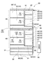
図1と図2に示すサーバー90は、サーバーケース91に複数のブレードサーバ50とラックサーバ51を脱着自在にセットしている。複数のブレードサーバ50は、エンクロージャー40に収納されて、エンクロージャー40をサーバーケース91に収納している。エンクロージャー40は、複数のブレードサーバ50を脱着自在にセットしており、その下部には、ブレードサーバ50に電力を供給する複数の電源ユニット60を脱着自在にセットしている。ラックサーバ51は、サーバーケース91の底部にを脱着自在にセットしている。無停電電源装置10、20、30は、サーバー90のブレードサーバ50に代わって脱着自在にセットされ、あるいは電源ユニット60に代わって脱着自在にセットされ、あるいは、ラックサーバ51に代わってサーバーケース91に脱着自在にセットされて、停電時にブレードサーバ50やラックサーバ51に電力を供給して所定の時間はサーバー90を動作状態に保持する。無停電電源装置10、20、30が、停電してからサーバー90を動作状態に保持する時間は、サーバー90を正常に終了処理できる時間よりも長く、たとえば2分間ないし10分間とする。図1と図2のエンクロージャー40は、ブレードサーバ50を複数段、すなわち2段に収納して、各段に複数列にブレードサーバ50を収納できるようにしている。さらに、図のエンクロージャー40は、ブレードサーバ50の下方に、複数の電源ユニット60を水平方向に並べて収納できる構造としている。
A
図のサーバーケース91は、複数のブレードサーバ50をセットしている複数のエンクロージャー40を脱着自在にセットできる構造としている。サーバーケース91は、エンクロージャー40の全ての位置にブレードサーバ50を使用しないので、ブレードサーバ50をセットしない部分に、ブレードサーバ50に代わって無停電電源装置10をセットできる。さらに、図のサーバーケース91は、底部に複数のラックサーバ51をセットできる構造としており、ラックサーバ51に代わって無停電電源装置30をセットしている。
The
サーバーケース91にセットされる無停電電源装置10、20、30の数は、停電状態でサーバー90を所定の時間動作状態にできる個数に設定される。1台の無停電電源装置10、20、30で停電後の所定の時間にわたって動作状態にできない場合は、複数の無停電電源装置10、20、30をセットする。セットされる複数の無停電電源装置10、20、30は並列に接続されて、サーバー90に電力を供給して、サーバー90を所定の時間動作状態とする。たとえば、消費電力を1kWとするサーバーは、500Wの無停電電源装置を少なくとも2台セットして、所定の時間動作状態にできる。
The number of uninterruptible power supplies 10, 20, and 30 set in the
無停電電源装置10、20、30は、ブレードサーバ50または電源ユニット60に代わってエンクロージャー40に脱着自在にセットでき、あるいはラックサーバ51に代わってサーバーケース91に脱着自在にセットできる外装ケース11、21、31と接続部12、22、32とを備えている。接続部12、22、32は、外装ケース11、21、31をエンクロージャー40やサーバーケース91の所定の位置にセットする状態で、無停電電源装置10、20、30をサーバー90の電源ライン43に接続する。
The
さらに、サーバーケース91は、図2に示すように、セットされるブレードサーバ50や電源ユニット60に接続されるバスラインや通信ライン7や電源ライン43等を設けているコネクトベイ41を背面に備えている。サーバーケース91の定位置にセットされるブレードサーバ50や電源ユニット60は、定位置にセットされる状態で、コネクトベイ41に接続される接続端子やコネクタからなる接続部52、62を設けており、この接続部52、62を介してコネクトベイ41に接続される。したがって、ブレードサーバ50や電源ユニット60に代わってセットされる無停電電源装置10、20も、サーバーケース91の定位置にセットされる状態で、コネクトベイ41に接続される接続部12、22を設けている。
Further, as shown in FIG. 2, the
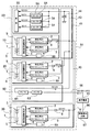
図3は、サーバー90のブロック図を示している。この図に示すサーバー90は、入力される商用電源95をブレードサーバ50の電源ライン43に供給する電源ユニット60を備えている。電源ユニット60は、入力される商用電源95を直流に変換するAC/DC変換回路63と、このAC/DC変換回路63から出力される直流をブレードサーバ50の電源ライン43に供給する直流12Vに変換するDC/DCコンバータ64とを備えている。この図のサーバー90は、ブレードサーバ50に電源回路53を内蔵しており、電源ユニット60から供給される直流電圧を、ブレードサーバ50に内蔵される負荷55である内部の回路に最適な電圧に変換するサブDC/DCコンバータ54を内蔵している。図のサーバー90は、電源ユニット60からブレードサーバ50の電源ライン43に供給する電圧を12Vとし、ブレードサーバ50は、この12Vを5V、3.3V、1Vに変換するサブDC/DCコンバータ54を内蔵している。図示しないが、ラックサーバ51もブレードサーバ50と同様の構造としており、電源ユニット60からラックサーバ51の電源ラインに供給される12Vの電圧を、ラックサーバ51に内蔵される負荷である内部の回路に最適な電圧に変換して供給している。
FIG. 3 shows a block diagram of the
無停電電源装置10、20、30は、充電できる二次電池1と、二次電池1の出力電圧をサーバー90の電源ライン43に供給できる直流電圧に降圧する降圧用のDC/DCコンバータ2と、電源ライン43の電圧を二次電池1の充電電圧に昇圧する昇圧用のDC/DCコンバータ3と、降圧用のDC/DCコンバータ2と昇圧用のDC/DCコンバータ3を制御する充放電制御回路4とを備えている。
The
二次電池1は、複数の素電池5を直列に接続して、定格電圧をサーバー90の電源ライン43の12Vよりも高く、すなわち13V以上であって60Vよりも低くしている。二次電池1の定格電圧が13Vよりも低いと、二次電池1の電圧を降圧してサーバー90の電源ライン43に供給できなくなり、反対に60Vよりも高いと、降圧用のDC/DCコンバータ2や昇圧用のDC/DCコンバータ3に使用する電子部品に高耐圧の素子を使用する必要があって、電力損失が大きくなる。また、二次電池1は、電圧を高くすることで、サーバー90の電源ライン43に供給する平均電流を小さくできる。したがって、二次電池1の定格電圧は、好ましくは30Vよりも高く、理想的には35Vよりも高くする。この二次電池1は、サーバー90の電源ライン43に供給する平均電流を約1/3にできる。さらに、二次電池1の電圧は、好ましくは50Vよりも低くして、使用する電子部品の耐圧を低くする。
In the
二次電池1の素電池5には、ニッケル水素電池やリチウムイオン電池を使用する。二次電池1は、たとえば400W〜2kWの電力を、2分間ないし10分間連続してサーバー90の電源ライン43に出力できる容量に設定される。
As the
降圧用のDC/DCコンバータ2は、二次電池1の出力をサーバー90の電源ライン43に供給できる電圧である12Vに降圧して出力する。降圧用のDC/DCコンバータ2の出力電圧は、12V±0.5Vの範囲に設定される。図の無停電電源装置10、20、30は、降圧用のDC/DCコンバータ2の出力側に逆流を阻止するダイオード6を接続している。
The step-down DC /
昇圧用のDC/DCコンバータ3は、サーバー90の電源ライン43の12Vの直流を二次電池1の充電電圧に昇圧して出力する。昇圧用のDC/DCコンバータ3は、出力電流を安定化する回路を内蔵している。素電池をニッケル水素電池とする二次電池を充電する昇圧用のDC/DCコンバータは、定電流回路でもって、素電池の充電電流を所定の電流に制限する。素電池をリチウムイオン電池とする二次電池を充電する昇圧用のDC/DCコンバータは、定電圧・定電流回路を内蔵して、二次電池の電圧上昇を制限しながら充電する。二次電池1を充電する昇圧用のDC/DCコンバータ3の出力電流は、電源ライン43に電力を供給する降圧用のDC/DCコンバータ2の出力電流に比較して極めて小さく、たとえば0.5A〜1Aに設定される。二次電池1を時間をかけて充電できるからである。出力電流の小さい昇圧用のDC/DCコンバータ3は、小さくて発熱を少なくできる。
The boosting DC /
充放電制御回路4は、二次電池1の残容量を検出し、昇圧用のDC/DCコンバータ3を制御し、あるいは昇圧用のDC/DCコンバータ3の出力側に設けている充電スイッチを制御して、二次電池1の残容量を常に設定範囲に保持する。時間が経過して二次電池1が放電されて残容量が設定範囲よりも小さくなると、充放電制御回路4は、昇圧用のDC/DCコンバータ3を動作状態とし、あるいは昇圧用のDC/DCコンバータ3の出力側に接続している充電スイッチをオンに切り換えて、二次電池1を充電し、残容量が設定値になると昇圧用のDC/DCコンバータ3の動作を停止し、あるいは昇圧用のDC/DCコンバータ3を動作状態としながら、充電スイッチをオフに切り換えて充電を停止する。充放電制御回路4は、たとえば、二次電池1の残容量を80%〜100%に保持するように、昇圧用のDC/DCコンバータ3の動作状態や充電スイッチを制御する。また、充放電制御回路4は、二次電池1の過放電を防止するように降圧用のDC/DCコンバータ2も制御する。停電して、二次電池1を放電してサーバー90に電力を供給する状態で、二次電池1の残容量が最低容量まで減少すると、降圧用のDC/DCコンバータ2の動作を停止して二次電池1の放電を停止する。
The charge /
充放電制御回路4は、商用電源95が停電したことを検出して、降圧用のDC/DCコンバータ2を動作状態に切り換える。充放電制御回路4は、停電しない状態においては、降圧用のDC/DCコンバータ2を動作状態としない。すなわち、非停電時において、降圧用のDC/DCコンバータ2は非動作状態に保持される。動作状態にある降圧用のDC/DCコンバータ2は、たとえ無負荷の状態にあっても相当な電力を消費する。たとえば、降圧用のDC/DCコンバータ2が、無負荷の状態において定格出力の2%の電力を消費するとしても、定格出力を500Wとするものにあっては、無負荷の動作状態において10W以上の電力を消費する。この電力は常に連続して消費されて無駄に電力を消費する。この弊害を防止するために、充放電制御回路4は、商用電源95が停電して、サーバー90の電源ユニット60から電源ライン43に12Vの直流を出力できないときにのみ、降圧用のDC/DCコンバータ2を動作状態に切り換える。動作状態に切り換えられた降圧用のDC/DCコンバータ2は、二次電池1の出力を12Vに降圧して、サーバー90の電源ライン43に供給して動作状態を保持する。
The charge /
降圧用のDC/DCコンバータ2は、商用電源95が停電して、サーバー90の電源ライン43の電圧が低下したことを検出して、動作状態に切り換えられるのではない。充放電制御回路4は、サーバー90から入力される停電信号で降圧用のDC/DCコンバータ2を動作状態に切り換える。サーバー90は、商用電源95の停電を瞬時に検出する停電検出回路65を内蔵しており、停電したことを検出すると、無停電電源装置10、20、30の充放電制御回路4に停電信号を出力する。充放電制御回路4は、サーバー90から停電信号を入力するために、通信ライン7を介してサーバー90に接続している。この無停電電源装置10、20、30は、商用電源95の停電を検出する必要がないので、商用電源95の交流ライン96に接続する必要がない。ただし、本発明の無停電電源装置は、充放電制御回路に商用電源の停電を検出する回路を設けて停電を検出することもできる。
The step-down DC /
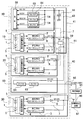
さらに、無停電電源装置10、20、30は、図4と図5に示すように、商用電源95の交流ライン96に接続されて停電を検出する停電検出回路97から有線または無線で伝送される停電信号を充放電制御回路4で検出して、降圧用のDC/DCコンバータ2を動作状態に切り換えることもできる。図の停電検出回路97は、サーバー90に内蔵されることなく、サーバー90の外部において商用電源95に直接に接続されて停電を検出する回路としている。この停電検出回路97は、図示しないが、商用電源95のコンセントにプラグを介して接続されて、商用電源95の停電時には、商用電源95が停電したことを検出して停電信号を出力する。停電検出回路97からの停電信号は、図4に示すように、有線である通信ライン98を介して無停電電源装置10、20、30の充放電制御回路に入力し、あるいは、図5に示すように、無線信号として無停電電源装置10、20、30の充放電制御回路4に伝送される。図5の無停電電源装置10、20、30は、停電検出回路97から送信される無線信号を受信する受信器99を内蔵しており、この受信器99で無線信号を受信して充放電制御回路4に入力している。ただ、停電検出回路97から送信される無線信号は、図6に示すように、サーバー側であるコネクトベイ41で受信した後、通信ライン7を介して無停電電源装置10、20、30の充放電制御回路4に入力することもできる。以上の構造は、サーバー90の外部に配設されて商用電源95に直接に接続される停電検出回路97で商用電源95の停電を瞬時に検出して、停電検出回路97から複数の無停電電源装置10、20、30に停電信号を伝送する。
Further, as shown in FIGS. 4 and 5, uninterruptible
サーバー90や充放電制御回路4は、商用電源95の停電を速やかに検出して、降圧用のDC/DCコンバータ2を速やかに動作状態に切り換える。商用電源95が停電してサーバー90の電源ユニット60から電源ライン43に12Vの直流を出力できなくなると、電源ライン43の電圧は次第に低下する。無停電電源装置10、20、30は、停電して電源ライン43の電圧が設定値まで低下するより先に降圧用のDC/DCコンバータ2を動作状態に切り換えて、電源ライン43に電力を供給する。サーバー90の電源ライン43は、大容量の電解コンデンサ44を接続しているので、停電しても瞬時には電圧が低下しない。電解コンデンサ44によって、電源ライン43の電圧が、設定電圧、すなわち、サーバー90を正常に動作できる最低電圧に低下する以前に、充放電制御回路4が降圧用のDC/DCコンバータ2を動作状態に切り換えて、二次電池1から電源ライン43に電力を供給して、サーバー90を停電後においても動作状態に保持する。停電して動作状態になった降圧用のDC/DCコンバータ2は、二次電池1からサーバー90の電源ライン43に動作電力を供給する。この状態で、サーバー90は終了処理などの所定の処理をして電源をオフに切り換える。二次電池1は、サーバー90が終了処理などの所定の処理を完了するまで、電源ライン43に動作電圧を供給する。サーバー90が所定の処理を終了して電源をオフに切り換えた後、充放電制御回路4は、降圧用のDC/DCコンバータ2の動作を停止し、あるいは二次電池1の残容量が最低容量よりも少なくなると、降圧用のDC/DCコンバータ2の動作を停止する。
The
充放電制御回路4は、停電を検出した後は、昇圧用のDC/DCコンバータ3も動作しない状態に切り換える。昇圧用のDC/DCコンバータ3は、降圧用のDC/DCコンバータ2に比較して出力が相当に小さいので、無負荷状態の消費電力は小さい。たとえば、36Vの二次電池1を0.5Aで充電する昇圧用のDC/DCコンバータ3は、定格出力が18Wと相当に小さい。このため、昇圧用のDC/DCコンバータ3の無負荷における消費電力も相当に小さくなる。たとえば、無負荷で定格出力の5%の電力を消費するとしても、0.9Wの電力を消費するに過ぎない。ただ、この昇圧用のDC/DCコンバータ3が停電時に動作状態になると、わずかであっても電力を消費する。また、停電時には、昇圧用のDC/DCコンバータ3が動作状態となって二次電池1を充電することはないので、充放電制御回路4は、停電を検出するときには、昇圧用のDC/DCコンバータ3を動作しない状態に切り換える。ただ、停電してサーバー90に電力を供給する時間は、たとえば2分間ないし10分間と短いので、この間に昇圧用のDC/DCコンバータ3を動作状態とすることもできる。
After detecting a power failure, the charge /
停電検出回路65は、サーバー90に内蔵されて、商用電源95の停電を瞬時に検出する。図3に示すサーバー90は、電源ユニット60に停電検出回路65を内蔵している。ただ、停電検出回路は、コネクトベイに内蔵することもできる。さらに、図4ないし図6に示すように、停電検出回路97は、サーバー90の外部において商用電源95の交流ライン96に接続して、商用電源95の停電を瞬時に検出することもできる。停電検出回路65、97は、図示しないが、商用電源95の交流を、積分回路又は微分回路でもって、商用電源95に対して90度位相のずれた変相信号とし、この変相信号と、交流電源である商用電源95から入力される入力信号の両方を別々に二乗回路で二乗し、各々の二乗回路の出力を加算回路で加算することで、商用電源95の停電を速やかに検出できる。
この停電検出回路65、97は、商用電源95から入力される入力信号をωとするとき、以下の式を実現して、A2の電圧の直流を出力する。すなわち、交流を入力して直流を出力する。この式においてAは、商用電源95のピーク電圧となる。
(Asinω)2+(Acosω)2=A2 が成立する。
この停電検出回路65、97は、商用電源95が入力される状態では、加算回路が一定の直流電圧(A2)を出力するが、停電して商用電源95の入力波形がサイン波からずれると、出力電圧が直ちに変化して、停電を検出できる。すなわち、入力される商用電源95が所定の周期で所定の電圧となるサインカーブに沿って変化しているかどうかを瞬時に判定して停電を検出する。停電検出回路65、97は、商用電源95が停電したことを検出すると、有線である通信ライン7、98を介して、あるいは無線によって、無停電電源装置10、20、30の充放電制御回路4に停電信号を伝達する。
The power
The power
(Asin ω) 2 + (A cos ω) 2 = A 2 holds.
In the state where the
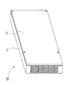
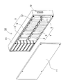
図7と図8は、ブレードサーバ50に代わって使用される無停電電源装置10を示している。この無停電電源装置10は、外装ケース11の前方に、充放電制御回路を実装する回路基板(図示せず)と降圧用のDC/DCコンバータ(図示せず)と昇圧用のDC/DCコンバータ(図示せず)とを内蔵し、後方に複数の素電池5からなる二次電池1を内蔵している。図の無停電電源装置20は、複数の素電池5を上下2段に配置して収納している。この無停電電源装置10は、多数の素電池5を収納して充電容量を大きくできる。このため、停電時に消費電力の大きい多数のブレードサーバ50を、長い時間にわたって連続して動作状態に保持できる。この無停電電源装置10は、図1と図2に示すように、エンクロージャー40の上部にセットされるブレードサーバ50に代わってセットされる。
7 and 8 show the
図9と図10は、電源ユニット60に代わってセットされる無停電電源装置20を示している。この無停電電源装置20は、外装ケース21の前方に、複数の素電池5からなる二次電池1を、後方に降圧用のDC/DCコンバータ2と昇圧用のDC/DCコンバータ3とを内蔵している。充放電制御回路(図示せず)は、内蔵される回路基板23に実装される。この無停電電源装置20は、図1と図2に示すように、エンクロージャー40の下部にセットされる電源ユニット60に代わってセットされる。この無停電電源装置20は、外装ケース21の前面に冷却ファン24を設けて、冷却ファン24でもって内蔵する発熱部品、たとえば降圧用のDC/DCコンバータ2や昇圧用のDC/DCコンバータ3のスイッチング素子のFET、整流用のダイオード、二次電池1などに強制送風して冷却する。外装ケース21は、前面の冷却ファン24が吸入する空気、あるいは排気する空気を通過させる多数の貫通孔26を前面パネル25に設けている。
9 and 10 show the
さらに、図の外装ケース21は、前面に、エンクロージャー40にロック状態でセットされるロックレバー27を設けている。このロックレバー27は、弾性金属板からなり、外装ケース21の側面に係止フック28を弾性的に突出させている。係止フック28は、エンクロージャー40に設けた係止部(図示せず)に係止されて、無停電電源装置20が抜けるのを阻止する。この無停電電源装置20は、ロックレバー27を操作して、係止フック28を外して、エンクロージャー40から外すことができる。
Further, the
以上の無停電電源装置10、20は、ブレードサーバ50に代わって、あるいは電源ユニット60に代わってエンクロージャー40にセットされて、エンクロージャー40に設けているコネクトベイ41に接続される接続部12、22を設けている。接続部12、22は、外装ケース11、21の奥部に設けられて、エンクロージャー40にセットされる状態で、コネクトベイ41に接続される。
The above uninterruptible
図11と図12は、ラックサーバ51に代わってブレードサーバケース91の底部にセットされる無停電電源装置30を示している。この無停電電源装置30は、外装ケース31の前方に、複数の素電池5からなる二次電池1を、後方に降圧用のDC/DCコンバータ2と昇圧用のDC/DCコンバータ3とを内蔵している。充放電制御回路(図示せず)は、内蔵される回路基板33に実装される。図の無停電電源装置30は、複数の二次電池1を平面状に並べて配置して収納している。この無停電電源装置30は、多数の二次電池1を収納して充電容量を大きくできる。このため、停電時に消費電力の大きい多数のブレードサーバ50やラックサーバ51を、長い時間にわたって連続して動作状態に保持できる。
11 and 12 show the
さらに、図12の無停電電源装置30は、外装ケース31の背面に冷却ファン34を設けて、冷却ファン34でもって内蔵する発熱部品、たとえば、降圧用のDC/DCコンバータ2や昇圧用のDC/DCコンバータ3のスイッチング素子のFET、整流用のダイオード、二次電池1などに強制送風して冷却する。外装ケース31は、背面の冷却ファン34が吸入する空気、あるいは排気する空気を通過させる多数の貫通孔36を前面パネル35に設けている。この無停電電源装置30は、内部の空気を冷却ファン34で強制的に換気して、無停電電源装置30の温度上昇を少なくできる。
Further, the
図1に示すサーバー90は、サーバーケース91の底部に無停電電源装置30をセットしているが、この無停電電源装置は、サーバーケースの上部であって、エンクロージャーの上方にセットすることも、サーバーケースの中間部であって、上下に配置される複数のエンクロージャーの間にセットすることもできる。
The
以上のサーバー90は、ブレードサーバ50や電源ユニット60に代わって無停電電源装置10、20をセットし、あるいは、ラックサーバ51に代わってサーバーケース91に無停電電源装置30をセットすることで、停電時に所定の時間は動作状態に保持できる。サーバー90は、複数の無停電電源装置10、20、30をセットして、停電時には、各々の無停電電源装置10、20、30から、ブレードサーバ50やラックサーバ51の電源ライン43に電力を供給して、動作状態に保持することができる。
The
さらに、サーバー90は、図2の鎖線で示すように、エンクロージャー40の背面でにできるスペース42に電源ユニット80を設置することもできる。図のサーバー90は、コネクトベイ41の上のスペース42に電源ユニット80を設置するが、サーバーは、コネクトベイの配置によって、コネクトベイの下や横のスペースに電源ユニットを配置することもできる。この電源ユニット80は、定位置にセットされる状態で、コネクトベイ41に接続される接続端子やコネクタからなる接続部82を設けており、この接続部82を介してコネクトベイ41に接続される。このサーバー90は、背面のスペース42に、電源ユニット80を脱着自在にセットし、また、この電源ユニット80に代わって無停電電源装置70をセットすることができる。
Furthermore, the
図13と図14は、サーバーケース91の背面であって、コネクトベイ41の上のスペース42に電源ユニット80に代わってセットされる無停電電源装置70を示している。この無停電電源装置70は、外装ケース71の前後に二次電池1と降圧用のDC/DCコンバータ2及び昇圧用のDC/DCコンバータ3を内蔵している。充放電制御回路(図示せず)は、内蔵される回路基板73に実装される。さらに、この無停電電源装置70は、外装ケース71の前面(サーバーケース91の背面側)に冷却ファン74を設けて、冷却ファン74でもって内蔵する発熱部品、たとえば降圧用のDC/DCコンバータ2や昇圧用のDC/DCコンバータ3のスイッチング素子のFET、整流用のダイオード、二次電池1などに強制送風して冷却する。外装ケース71は、前面の冷却ファン74が吸入する空気、あるいは排気する空気を通過させる貫通孔76を前面パネル75に設けている。
FIGS. 13 and 14 show the
さらに、図の外装ケース71は、前面に、エンクロージャー40にロック状態でセットされるロックレバー77を設けている。このロックレバー77は、弾性金属板からなり、外装ケース71の上面に係止フック78を弾性的に突出させている。係止フック78は、エンクロージャー40に設けた係止部(図示せず)に係止されて、無停電電源装置70が抜けるのを阻止する。この無停電電源装置70は、ロックレバー77を操作して、係止フック78を外して、エンクロージャー40から外すことができる。
Further, the
この無停電電源装置70も、電源ユニット80に代わってサーバーケース91の定位置にセットされる状態で、コネクトベイ41に接続される接続部72を設けている。接続部72は、外装ケース71の奥部に設けられて、エンクロージャー40にセットされる状態で、コネクトベイ41に接続される。サーバー90は、電源ユニット80に代わって無停電電源装置70をセットすることで、停電時に所定の時間は動作状態に保持できる。サーバー90は、複数の無停電電源装置70をセットして、停電時には、各々の無停電電源装置70から、ブレードサーバ50やラックサーバ51の電源ライン43に電力を供給して、動作状態に保持することができる。
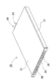
なお、図13及び図14では、厚みのある板状である箱型の無停電電源装置70において、一側面を下側にして配置しているが、一平面(図14における背面)を下側に配置して、換言すれば、図13及び図14の状態より90度回転した状態で、スペース42に設定することもできる。
The
13 and 14, the box-shaped
1…二次電池
2…降圧用のDC/DCコンバータ
3…昇圧用のDC/DCコンバータ
4…充放電制御回路
5…素電池
6…ダイオード
7…通信ライン
10…無停電電源装置
11…外装ケース
12…接続部
20…無停電電源装置
21…外装ケース
22…接続部
23…回路基板
24…冷却ファン
25…前面パネル
26…貫通孔
27…ロックレバー
28…係止フック
30…無停電電源装置
31…外装ケース
32…接続部
33…回路基板
34…冷却ファン
35…前面パネル
36…貫通孔
40…エンクロージャー
41…コネクトベイ
42…スペース
43…電源ライン
44…電解コンデンサ
50…ブレードサーバ
51…ラックサーバ
52…装着部
53…電源回路
54…サブDC/DCコンバータ
55…負荷
60…電源ユニット
62…装着部
63…AC/DC変換回路
64…DC/DCコンバータ
65…停電検出回路
70…無停電電源装置
71…外装ケース
72…接続部
73…回路基板
74…冷却ファン
75…前面パネル
76…貫通孔
77…ロックレバー
78…係止フック
80…電源ユニット
82…装着部
90…サーバー
91…サーバーケース
95…商用電源
96…交流ライン
97…停電検出回路
98…通信ライン
99…受信器
DESCRIPTION OF
Claims (8)
前記サーバー(90)の電源ライン(43)に接続されて電源ライン(43)の電圧を二次電池(1)の充電電圧に昇圧する昇圧用のDC/DCコンバータ(3)と、この昇圧用のDC/DCコンバータ(3)で充電される定格電圧を13V以上であって60V以下とする二次電池(1)と、この二次電池(1)の電圧を電源ライン(43)の電圧に降圧してサーバー(90)の電源ライン(43)に出力する降圧用のDC/DCコンバータ(2)と、前記昇圧用のDC/DCコンバータ(3)と降圧用のDC/DCコンバータ(2)とを制御する充放電制御回路(4)とを備え、
前記サーバー(90)に電力を供給する商用電源(95)の停電状態において、前記二次電池(1)の出力電圧が、前記降圧用のDC/DCコンバータ(2)でもって、前記サーバー(90)の電源ライン(43)の電圧に降圧して電源ライン(43)に出力されて、前記サーバー(90)を動作状態を保持するようにしてなるサーバーの無停電電源装置。 It is housed in the server case (91) of the server (90) and is connected to the DC 12V power line (43) of the server (90) via a DC / DC converter and charged by the power of the power line (43). And an uninterruptible power supply for a server (90) comprising a secondary battery (1) for supplying power to a power line (43),
A boosting DC / DC converter (3) connected to the power line (43) of the server (90) and boosting the voltage of the power line (43) to the charging voltage of the secondary battery (1); The secondary battery (1) whose rated voltage charged by the DC / DC converter (3) is 13V or more and 60V or less, and the voltage of the secondary battery (1) is changed to the voltage of the power line (43). Step-down DC / DC converter (2) for stepping down and outputting to power supply line (43) of server (90), step-up DC / DC converter (3) and step-down DC / DC converter (2) A charge / discharge control circuit (4) for controlling
In the power failure state of the commercial power supply (95) that supplies power to the server (90), the output voltage of the secondary battery (1) is reduced by the DC / DC converter (2) for step-down. The server uninterruptible power supply is configured to keep the server (90) in an operating state by being stepped down to the voltage of the power line (43) and output to the power line (43).
Priority Applications (3)
| Application Number | Priority Date | Filing Date | Title |
|---|---|---|---|
| JP2009279900A JP5583394B2 (en) | 2009-12-09 | 2009-12-09 | Server uninterruptible power supply |
| EP20100015445 EP2333931A3 (en) | 2009-12-09 | 2010-12-08 | Server uninterruptable power supply |
| US12/962,997 US20110133559A1 (en) | 2009-12-09 | 2010-12-08 | Server uninterruptable power supply |
Applications Claiming Priority (1)
| Application Number | Priority Date | Filing Date | Title |
|---|---|---|---|
| JP2009279900A JP5583394B2 (en) | 2009-12-09 | 2009-12-09 | Server uninterruptible power supply |
Publications (2)
| Publication Number | Publication Date |
|---|---|
| JP2011125123A true JP2011125123A (en) | 2011-06-23 |
| JP5583394B2 JP5583394B2 (en) | 2014-09-03 |
Family
ID=43769315
Family Applications (1)
| Application Number | Title | Priority Date | Filing Date |
|---|---|---|---|
| JP2009279900A Active JP5583394B2 (en) | 2009-12-09 | 2009-12-09 | Server uninterruptible power supply |
Country Status (3)
| Country | Link |
|---|---|
| US (1) | US20110133559A1 (en) |
| EP (1) | EP2333931A3 (en) |
| JP (1) | JP5583394B2 (en) |
Cited By (5)
| Publication number | Priority date | Publication date | Assignee | Title |
|---|---|---|---|---|
| WO2014132452A1 (en) * | 2013-03-01 | 2014-09-04 | 富士電機株式会社 | Power supply system |
| KR20150139250A (en) * | 2014-06-03 | 2015-12-11 | 주식회사 엘지씨엔에스 | Mobile energy storage system |
| JP2016012353A (en) * | 2014-06-27 | 2016-01-21 | ブル サス | Micro power failure compensation module for servers |
| JP6048572B2 (en) * | 2013-03-15 | 2016-12-21 | 富士電機株式会社 | Uninterruptible power system |
| JP2021182850A (en) * | 2020-04-26 | 2021-11-25 | ペキン バイドゥ ネットコム サイエンス アンド テクノロジー カンパニー リミテッドBeijing Baidu Netcom Science And Technology Co., Ltd. | Backup power supply system and detection method for server cabinet, as well as computer program |
Families Citing this family (37)
| Publication number | Priority date | Publication date | Assignee | Title |
|---|---|---|---|---|
| TWI448886B (en) * | 2011-07-28 | 2014-08-11 | Quanta Comp Inc | Rack server system and control method thereof |
| EP2624412A1 (en) * | 2012-02-06 | 2013-08-07 | Siemens Aktiengesellschaft | Power supply |
| TW201335739A (en) * | 2012-02-29 | 2013-09-01 | Quanta Comp Inc | Server system |
| US9397520B2 (en) * | 2012-12-14 | 2016-07-19 | Sensormatic Electronics, LLC | Intelligent adaptive power supply |
| US9800087B2 (en) | 2013-10-28 | 2017-10-24 | Virtual Power Systems, Inc. | Multi-level data center consolidated power control |
| US11126242B2 (en) | 2013-10-28 | 2021-09-21 | Virtual Power Systems, Inc. | Time varying power management within datacenters |
| US10429914B2 (en) | 2013-10-28 | 2019-10-01 | Virtual Power Systems, Inc. | Multi-level data center using consolidated power control |
| US10747289B2 (en) | 2013-10-28 | 2020-08-18 | Virtual Power Systems, Inc. | Data center power manipulation |
| CN104811036B (en) * | 2014-01-28 | 2018-01-26 | 台达电子企业管理(上海)有限公司 | Multi-power supply system and its control method |
| US10797490B2 (en) * | 2014-03-26 | 2020-10-06 | Intersil Americas LLC | Battery charge system with transition control that protects adapter components when transitioning from battery mode to adapter mode |
| US20170047772A1 (en) * | 2014-04-18 | 2017-02-16 | Schneider Electric It Corporation | System and methods for distributed uninterruptable power supplies |
| TWI539882B (en) * | 2014-07-16 | 2016-06-21 | 廣達電腦股份有限公司 | Server |
| WO2016019486A1 (en) * | 2014-08-04 | 2016-02-11 | 深圳欧陆通电子有限公司 | Power supply and battery management module compatible with common redundant power supply |
| CN104377806A (en) * | 2014-11-13 | 2015-02-25 | 深圳市汇川控制技术有限公司 | Power-down control circuit and method |
| US9641659B2 (en) * | 2014-12-12 | 2017-05-02 | Boyce Technologies Inc. | Access node and method |
| US10548237B2 (en) * | 2015-02-20 | 2020-01-28 | Hewlett Packard Enterprise Development Lp | Externally accessible replaceable power source |
| TW201714042A (en) * | 2015-10-13 | 2017-04-16 | 鴻海精密工業股份有限公司 | Container data center |
| WO2017096173A1 (en) * | 2015-12-03 | 2017-06-08 | Vapor IO Inc. | Compact uninteruptable power supply |
| US11068037B2 (en) | 2016-01-21 | 2021-07-20 | Hewlett Packard Enterprise Development Lp | Device having main and backup power |
| DE102016201407A1 (en) * | 2016-01-29 | 2017-08-03 | Robert Bosch Gmbh | Device for operating a mobile electrical energy storage and energy storage system |
| US11455021B2 (en) | 2016-08-18 | 2022-09-27 | Cato | Datacenter power management using AC and DC power sources |
| US10585468B2 (en) | 2016-08-18 | 2020-03-10 | Virtual Power Systems, Inc. | Datacenter power management using dynamic redundancy |
| US11107016B2 (en) | 2016-08-18 | 2021-08-31 | Virtual Power Systems, Inc. | Augmented power control within a datacenter using predictive modeling |
| US11461513B2 (en) | 2016-08-18 | 2022-10-04 | Cato | Data center power scenario simulation |
| CN205970916U (en) * | 2016-08-29 | 2017-02-22 | 上海蔚来汽车有限公司 | Modularization storage battery car |
| US10969846B2 (en) | 2017-05-25 | 2021-04-06 | Virtual Power Systems, Inc. | Secure communication initiation and execution for datacenter power control |
| US10873206B2 (en) * | 2017-05-30 | 2020-12-22 | Schneider Electric It Corporation | System and method for power storage and distribution |
| US20190064898A1 (en) * | 2017-08-31 | 2019-02-28 | Schneider Electric It Corporation | Rack mount ups dock with bypass capability |
| US11216059B2 (en) | 2018-03-05 | 2022-01-04 | Virtual Power Systems, Inc. | Dynamic tiering of datacenter power for workloads |
| US11102900B2 (en) | 2019-04-22 | 2021-08-24 | Transportation Ip Holdings, Llc | Electrical power delivery system |
| US11464138B2 (en) | 2019-04-22 | 2022-10-04 | Transportation Ip Holdings, Llc | Module panel and method for an electrical power delivery system |
| US11239521B2 (en) | 2019-04-22 | 2022-02-01 | Transportation Ip Holdings, Llc | Electrical power delivery system with a support structure |
| US11052742B2 (en) | 2019-04-22 | 2021-07-06 | Transportation Ip Holdings, Llc | Mounting system for an electrical power delivery system |
| US11706896B2 (en) | 2019-04-22 | 2023-07-18 | Transportation Ip Holdings, Llc | Modular rack system and method |
| US11545851B2 (en) * | 2020-08-10 | 2023-01-03 | Saudi Arabian Oil Company | Systems, methods, and apparatuses for distributing backup electrical power |
| CN114449826B (en) * | 2022-02-15 | 2024-01-05 | 南京鼎耀电力科技有限公司 | Single-phase liquid cooling rack |
| JP2025537994A (en) | 2023-05-15 | 2025-11-20 | エルジー エナジー ソリューション リミテッド | Uninterruptible power supply and method of operating the same |
Citations (6)
| Publication number | Priority date | Publication date | Assignee | Title |
|---|---|---|---|---|
| JPH11196541A (en) * | 1997-12-26 | 1999-07-21 | Fujitsu Ltd | Power supply |
| JP2000014043A (en) * | 1998-06-05 | 2000-01-14 | Internatl Business Mach Corp <Ibm> | Uninterruptive power supply |
| JP2003309935A (en) * | 2002-04-16 | 2003-10-31 | Hitachi Ltd | DC backup power supply |
| JP2004153890A (en) * | 2002-10-29 | 2004-05-27 | Omron Corp | Power supply and uninterruptible power supply unit |
| US20070217125A1 (en) * | 2006-03-17 | 2007-09-20 | Eaton Power Quality Corporation | Uninterruptible Power Distribution Systems and Methods Using Distributed Power Distribution Units |
| JP2010088211A (en) * | 2008-09-30 | 2010-04-15 | Sanyo Electric Co Ltd | Backup power supply of blade server |
Family Cites Families (6)
| Publication number | Priority date | Publication date | Assignee | Title |
|---|---|---|---|---|
| US7098557B2 (en) * | 2003-05-15 | 2006-08-29 | Stmicroelectronics, Inc. | Constant voltage discharge device |
| JP2006042495A (en) | 2004-07-27 | 2006-02-09 | Pioneer Electronic Corp | Power supply system |
| US7421599B2 (en) * | 2005-06-09 | 2008-09-02 | International Business Machines Corporation | Power management server and method for managing power consumption |
| US7517241B2 (en) * | 2006-11-30 | 2009-04-14 | International Business Machines Corporation | Apparatus for releasing latching connectors |
| US8080900B2 (en) * | 2007-07-18 | 2011-12-20 | Exaflop Llc | Direct-coupled IT load |
| US8117613B2 (en) * | 2009-04-08 | 2012-02-14 | Microsoft Corporation | Optimized virtual machine migration mechanism |
-
2009
- 2009-12-09 JP JP2009279900A patent/JP5583394B2/en active Active
-
2010
- 2010-12-08 US US12/962,997 patent/US20110133559A1/en not_active Abandoned
- 2010-12-08 EP EP20100015445 patent/EP2333931A3/en not_active Withdrawn
Patent Citations (6)
| Publication number | Priority date | Publication date | Assignee | Title |
|---|---|---|---|---|
| JPH11196541A (en) * | 1997-12-26 | 1999-07-21 | Fujitsu Ltd | Power supply |
| JP2000014043A (en) * | 1998-06-05 | 2000-01-14 | Internatl Business Mach Corp <Ibm> | Uninterruptive power supply |
| JP2003309935A (en) * | 2002-04-16 | 2003-10-31 | Hitachi Ltd | DC backup power supply |
| JP2004153890A (en) * | 2002-10-29 | 2004-05-27 | Omron Corp | Power supply and uninterruptible power supply unit |
| US20070217125A1 (en) * | 2006-03-17 | 2007-09-20 | Eaton Power Quality Corporation | Uninterruptible Power Distribution Systems and Methods Using Distributed Power Distribution Units |
| JP2010088211A (en) * | 2008-09-30 | 2010-04-15 | Sanyo Electric Co Ltd | Backup power supply of blade server |
Cited By (10)
| Publication number | Priority date | Publication date | Assignee | Title |
|---|---|---|---|---|
| WO2014132452A1 (en) * | 2013-03-01 | 2014-09-04 | 富士電機株式会社 | Power supply system |
| JPWO2014132452A1 (en) * | 2013-03-01 | 2017-02-02 | 富士電機株式会社 | Power system |
| JP6048572B2 (en) * | 2013-03-15 | 2016-12-21 | 富士電機株式会社 | Uninterruptible power system |
| US9899835B2 (en) | 2013-03-15 | 2018-02-20 | Fuji Electric Co., Ltd. | Uninterruptible power supply system |
| KR20150139250A (en) * | 2014-06-03 | 2015-12-11 | 주식회사 엘지씨엔에스 | Mobile energy storage system |
| KR101602697B1 (en) * | 2014-06-03 | 2016-03-11 | 주식회사 엘지씨엔에스 | Mobile energy storage system |
| JP2016012353A (en) * | 2014-06-27 | 2016-01-21 | ブル サス | Micro power failure compensation module for servers |
| JP2021182850A (en) * | 2020-04-26 | 2021-11-25 | ペキン バイドゥ ネットコム サイエンス アンド テクノロジー カンパニー リミテッドBeijing Baidu Netcom Science And Technology Co., Ltd. | Backup power supply system and detection method for server cabinet, as well as computer program |
| US11519970B2 (en) | 2020-04-26 | 2022-12-06 | Beijing Baidu Netcom Science And Technology Co., Ltd. | Server cabinet power backup system and testing method thereof |
| JP7184945B2 (en) | 2020-04-26 | 2022-12-06 | ベイジン バイドゥ ネットコム サイエンス テクノロジー カンパニー リミテッド | BACKUP POWER SYSTEM FOR SERVER CABINET AND DETECTION METHOD AND COMPUTER PROGRAM |
Also Published As
| Publication number | Publication date |
|---|---|
| JP5583394B2 (en) | 2014-09-03 |
| US20110133559A1 (en) | 2011-06-09 |
| EP2333931A2 (en) | 2011-06-15 |
| EP2333931A3 (en) | 2014-03-19 |
Similar Documents
| Publication | Publication Date | Title |
|---|---|---|
| JP5583394B2 (en) | Server uninterruptible power supply | |
| JP2011125124A (en) | Server and uninterruptible power supply housed in the server | |
| TWI342096B (en) | Switching power supply unit and disk array system | |
| JP3908076B2 (en) | DC backup power supply | |
| TWI396070B (en) | Power management system capable of saving power and optimizing operating efficiency of power supplies for providing power with back-up or redundancy to plural loads | |
| TWI433441B (en) | Solar powered apparatus and method of providing power to dc-capable ac appliance | |
| US20110148194A1 (en) | High voltage direct current uninterruptible power supply system with multiple input power sources | |
| CN108702023B (en) | Rack power system and method | |
| US10798853B2 (en) | Inverter device to achieve improved heat dissipation efficiency | |
| AU2012275336B2 (en) | Systems and methods for operating an uninterruptible power supply | |
| JP2010088211A (en) | Backup power supply of blade server | |
| US8890374B2 (en) | Uninterruptible power supply system for avoiding arcing generation and cabinet thereof | |
| CN104426387A (en) | System and method for frame mountable modular direct current power unit | |
| JP2006505240A (en) | High quality power supply device | |
| US20070103114A1 (en) | Enhanced portable battery powered electrical appliance | |
| JP2011065259A (en) | Equipment control system | |
| US20210184485A1 (en) | Portable solar power management system | |
| KR20190067681A (en) | Method for supplying power and apparatus for supplying power | |
| JP5296161B2 (en) | Power supply system | |
| JP2014057384A (en) | Power supply system including electrical equipment | |
| JP6519781B2 (en) | Power storage system and management device | |
| US20190335606A1 (en) | Universal power supply | |
| CN212063510U (en) | Integrated off-grid energy storage system and device | |
| US20240258809A1 (en) | Mobile power supply system comprising cascaded multi-level inverter | |
| CN103748762B (en) | For running the system and method for uninterrupted power source |
Legal Events
| Date | Code | Title | Description |
|---|---|---|---|
| A621 | Written request for application examination |
Free format text: JAPANESE INTERMEDIATE CODE: A621 Effective date: 20121107 |
|
| A977 | Report on retrieval |
Free format text: JAPANESE INTERMEDIATE CODE: A971007 Effective date: 20131025 |
|
| A131 | Notification of reasons for refusal |
Free format text: JAPANESE INTERMEDIATE CODE: A131 Effective date: 20131126 |
|
| A521 | Request for written amendment filed |
Free format text: JAPANESE INTERMEDIATE CODE: A523 Effective date: 20140124 |
|
| A131 | Notification of reasons for refusal |
Free format text: JAPANESE INTERMEDIATE CODE: A131 Effective date: 20140318 |
|
| A521 | Request for written amendment filed |
Free format text: JAPANESE INTERMEDIATE CODE: A523 Effective date: 20140513 |
|
| A711 | Notification of change in applicant |
Free format text: JAPANESE INTERMEDIATE CODE: A711 Effective date: 20140514 |
|
| TRDD | Decision of grant or rejection written | ||
| A01 | Written decision to grant a patent or to grant a registration (utility model) |
Free format text: JAPANESE INTERMEDIATE CODE: A01 Effective date: 20140708 |
|
| A61 | First payment of annual fees (during grant procedure) |
Free format text: JAPANESE INTERMEDIATE CODE: A61 Effective date: 20140716 |
|
| R150 | Certificate of patent or registration of utility model |
Ref document number: 5583394 Country of ref document: JP Free format text: JAPANESE INTERMEDIATE CODE: R150 |
|
| S531 | Written request for registration of change of domicile |
Free format text: JAPANESE INTERMEDIATE CODE: R313531 |
|
| R350 | Written notification of registration of transfer |
Free format text: JAPANESE INTERMEDIATE CODE: R350 |
|
| R250 | Receipt of annual fees |
Free format text: JAPANESE INTERMEDIATE CODE: R250 |
|
| R250 | Receipt of annual fees |
Free format text: JAPANESE INTERMEDIATE CODE: R250 |
|
| R250 | Receipt of annual fees |
Free format text: JAPANESE INTERMEDIATE CODE: R250 |
|
| R250 | Receipt of annual fees |
Free format text: JAPANESE INTERMEDIATE CODE: R250 |
|
| R250 | Receipt of annual fees |
Free format text: JAPANESE INTERMEDIATE CODE: R250 |
|
| R250 | Receipt of annual fees |
Free format text: JAPANESE INTERMEDIATE CODE: R250 |
|
| R250 | Receipt of annual fees |
Free format text: JAPANESE INTERMEDIATE CODE: R250 |
|
| R250 | Receipt of annual fees |
Free format text: JAPANESE INTERMEDIATE CODE: R250 |
|
| R250 | Receipt of annual fees |
Free format text: JAPANESE INTERMEDIATE CODE: R250 |