JP2011073959A - Thermal insulation material - Google Patents
Thermal insulation material Download PDFInfo
- Publication number
- JP2011073959A JP2011073959A JP2010187403A JP2010187403A JP2011073959A JP 2011073959 A JP2011073959 A JP 2011073959A JP 2010187403 A JP2010187403 A JP 2010187403A JP 2010187403 A JP2010187403 A JP 2010187403A JP 2011073959 A JP2011073959 A JP 2011073959A
- Authority
- JP
- Japan
- Prior art keywords
- molded body
- heat insulating
- insulating material
- fiber
- connecting member
- Prior art date
- Legal status (The legal status is an assumption and is not a legal conclusion. Google has not performed a legal analysis and makes no representation as to the accuracy of the status listed.)
- Granted
Links
Images



Classifications
-
- B—PERFORMING OPERATIONS; TRANSPORTING
- B32—LAYERED PRODUCTS
- B32B—LAYERED PRODUCTS, i.e. PRODUCTS BUILT-UP OF STRATA OF FLAT OR NON-FLAT, e.g. CELLULAR OR HONEYCOMB, FORM
- B32B7/00—Layered products characterised by the relation between layers; Layered products characterised by the relative orientation of features between layers, or by the relative values of a measurable parameter between layers, i.e. products comprising layers having different physical, chemical or physicochemical properties; Layered products characterised by the interconnection of layers
- B32B7/04—Interconnection of layers
-
- B—PERFORMING OPERATIONS; TRANSPORTING
- B32—LAYERED PRODUCTS
- B32B—LAYERED PRODUCTS, i.e. PRODUCTS BUILT-UP OF STRATA OF FLAT OR NON-FLAT, e.g. CELLULAR OR HONEYCOMB, FORM
- B32B3/00—Layered products comprising a layer with external or internal discontinuities or unevennesses, or a layer of non-planar shape; Layered products comprising a layer having particular features of form
- B32B3/02—Layered products comprising a layer with external or internal discontinuities or unevennesses, or a layer of non-planar shape; Layered products comprising a layer having particular features of form characterised by features of form at particular places, e.g. in edge regions
- B32B3/08—Layered products comprising a layer with external or internal discontinuities or unevennesses, or a layer of non-planar shape; Layered products comprising a layer having particular features of form characterised by features of form at particular places, e.g. in edge regions characterised by added members at particular parts
-
- B—PERFORMING OPERATIONS; TRANSPORTING
- B32—LAYERED PRODUCTS
- B32B—LAYERED PRODUCTS, i.e. PRODUCTS BUILT-UP OF STRATA OF FLAT OR NON-FLAT, e.g. CELLULAR OR HONEYCOMB, FORM
- B32B5/00—Layered products characterised by the non- homogeneity or physical structure, i.e. comprising a fibrous, filamentary, particulate or foam layer; Layered products characterised by having a layer differing constitutionally or physically in different parts
- B32B5/16—Layered products characterised by the non- homogeneity or physical structure, i.e. comprising a fibrous, filamentary, particulate or foam layer; Layered products characterised by having a layer differing constitutionally or physically in different parts characterised by features of a layer formed of particles, e.g. chips, powder or granules
-
- B—PERFORMING OPERATIONS; TRANSPORTING
- B32—LAYERED PRODUCTS
- B32B—LAYERED PRODUCTS, i.e. PRODUCTS BUILT-UP OF STRATA OF FLAT OR NON-FLAT, e.g. CELLULAR OR HONEYCOMB, FORM
- B32B5/00—Layered products characterised by the non- homogeneity or physical structure, i.e. comprising a fibrous, filamentary, particulate or foam layer; Layered products characterised by having a layer differing constitutionally or physically in different parts
- B32B5/22—Layered products characterised by the non- homogeneity or physical structure, i.e. comprising a fibrous, filamentary, particulate or foam layer; Layered products characterised by having a layer differing constitutionally or physically in different parts characterised by the presence of two or more layers which are next to each other and are fibrous, filamentary, formed of particles or foamed
- B32B5/24—Layered products characterised by the non- homogeneity or physical structure, i.e. comprising a fibrous, filamentary, particulate or foam layer; Layered products characterised by having a layer differing constitutionally or physically in different parts characterised by the presence of two or more layers which are next to each other and are fibrous, filamentary, formed of particles or foamed one layer being a fibrous or filamentary layer
- B32B5/245—Layered products characterised by the non- homogeneity or physical structure, i.e. comprising a fibrous, filamentary, particulate or foam layer; Layered products characterised by having a layer differing constitutionally or physically in different parts characterised by the presence of two or more layers which are next to each other and are fibrous, filamentary, formed of particles or foamed one layer being a fibrous or filamentary layer another layer next to it being a foam layer
-
- B—PERFORMING OPERATIONS; TRANSPORTING
- B32—LAYERED PRODUCTS
- B32B—LAYERED PRODUCTS, i.e. PRODUCTS BUILT-UP OF STRATA OF FLAT OR NON-FLAT, e.g. CELLULAR OR HONEYCOMB, FORM
- B32B5/00—Layered products characterised by the non- homogeneity or physical structure, i.e. comprising a fibrous, filamentary, particulate or foam layer; Layered products characterised by having a layer differing constitutionally or physically in different parts
- B32B5/22—Layered products characterised by the non- homogeneity or physical structure, i.e. comprising a fibrous, filamentary, particulate or foam layer; Layered products characterised by having a layer differing constitutionally or physically in different parts characterised by the presence of two or more layers which are next to each other and are fibrous, filamentary, formed of particles or foamed
- B32B5/24—Layered products characterised by the non- homogeneity or physical structure, i.e. comprising a fibrous, filamentary, particulate or foam layer; Layered products characterised by having a layer differing constitutionally or physically in different parts characterised by the presence of two or more layers which are next to each other and are fibrous, filamentary, formed of particles or foamed one layer being a fibrous or filamentary layer
- B32B5/26—Layered products characterised by the non- homogeneity or physical structure, i.e. comprising a fibrous, filamentary, particulate or foam layer; Layered products characterised by having a layer differing constitutionally or physically in different parts characterised by the presence of two or more layers which are next to each other and are fibrous, filamentary, formed of particles or foamed one layer being a fibrous or filamentary layer another layer next to it also being fibrous or filamentary
-
- B—PERFORMING OPERATIONS; TRANSPORTING
- B32—LAYERED PRODUCTS
- B32B—LAYERED PRODUCTS, i.e. PRODUCTS BUILT-UP OF STRATA OF FLAT OR NON-FLAT, e.g. CELLULAR OR HONEYCOMB, FORM
- B32B5/00—Layered products characterised by the non- homogeneity or physical structure, i.e. comprising a fibrous, filamentary, particulate or foam layer; Layered products characterised by having a layer differing constitutionally or physically in different parts
- B32B5/22—Layered products characterised by the non- homogeneity or physical structure, i.e. comprising a fibrous, filamentary, particulate or foam layer; Layered products characterised by having a layer differing constitutionally or physically in different parts characterised by the presence of two or more layers which are next to each other and are fibrous, filamentary, formed of particles or foamed
- B32B5/30—Layered products characterised by the non- homogeneity or physical structure, i.e. comprising a fibrous, filamentary, particulate or foam layer; Layered products characterised by having a layer differing constitutionally or physically in different parts characterised by the presence of two or more layers which are next to each other and are fibrous, filamentary, formed of particles or foamed one layer being formed of particles, e.g. chips, granules, powder
-
- B—PERFORMING OPERATIONS; TRANSPORTING
- B32—LAYERED PRODUCTS
- B32B—LAYERED PRODUCTS, i.e. PRODUCTS BUILT-UP OF STRATA OF FLAT OR NON-FLAT, e.g. CELLULAR OR HONEYCOMB, FORM
- B32B7/00—Layered products characterised by the relation between layers; Layered products characterised by the relative orientation of features between layers, or by the relative values of a measurable parameter between layers, i.e. products comprising layers having different physical, chemical or physicochemical properties; Layered products characterised by the interconnection of layers
- B32B7/04—Interconnection of layers
- B32B7/08—Interconnection of layers by mechanical means
-
- B—PERFORMING OPERATIONS; TRANSPORTING
- B32—LAYERED PRODUCTS
- B32B—LAYERED PRODUCTS, i.e. PRODUCTS BUILT-UP OF STRATA OF FLAT OR NON-FLAT, e.g. CELLULAR OR HONEYCOMB, FORM
- B32B2262/00—Composition or structural features of fibres which form a fibrous or filamentary layer or are present as additives
- B32B2262/10—Inorganic fibres
-
- B—PERFORMING OPERATIONS; TRANSPORTING
- B32—LAYERED PRODUCTS
- B32B—LAYERED PRODUCTS, i.e. PRODUCTS BUILT-UP OF STRATA OF FLAT OR NON-FLAT, e.g. CELLULAR OR HONEYCOMB, FORM
- B32B2264/00—Composition or properties of particles which form a particulate layer or are present as additives
- B32B2264/02—Synthetic macromolecular particles
-
- B—PERFORMING OPERATIONS; TRANSPORTING
- B32—LAYERED PRODUCTS
- B32B—LAYERED PRODUCTS, i.e. PRODUCTS BUILT-UP OF STRATA OF FLAT OR NON-FLAT, e.g. CELLULAR OR HONEYCOMB, FORM
- B32B2266/00—Composition of foam
- B32B2266/02—Organic
- B32B2266/0214—Materials belonging to B32B27/00
- B32B2266/025—Polyolefin
-
- B—PERFORMING OPERATIONS; TRANSPORTING
- B32—LAYERED PRODUCTS
- B32B—LAYERED PRODUCTS, i.e. PRODUCTS BUILT-UP OF STRATA OF FLAT OR NON-FLAT, e.g. CELLULAR OR HONEYCOMB, FORM
- B32B2266/00—Composition of foam
- B32B2266/02—Organic
- B32B2266/0214—Materials belonging to B32B27/00
- B32B2266/0278—Polyurethane
-
- B—PERFORMING OPERATIONS; TRANSPORTING
- B32—LAYERED PRODUCTS
- B32B—LAYERED PRODUCTS, i.e. PRODUCTS BUILT-UP OF STRATA OF FLAT OR NON-FLAT, e.g. CELLULAR OR HONEYCOMB, FORM
- B32B2307/00—Properties of the layers or laminate
- B32B2307/30—Properties of the layers or laminate having particular thermal properties
- B32B2307/304—Insulating
-
- B—PERFORMING OPERATIONS; TRANSPORTING
- B32—LAYERED PRODUCTS
- B32B—LAYERED PRODUCTS, i.e. PRODUCTS BUILT-UP OF STRATA OF FLAT OR NON-FLAT, e.g. CELLULAR OR HONEYCOMB, FORM
- B32B2307/00—Properties of the layers or laminate
- B32B2307/50—Properties of the layers or laminate having particular mechanical properties
- B32B2307/546—Flexural strength; Flexion stiffness
-
- B—PERFORMING OPERATIONS; TRANSPORTING
- B32—LAYERED PRODUCTS
- B32B—LAYERED PRODUCTS, i.e. PRODUCTS BUILT-UP OF STRATA OF FLAT OR NON-FLAT, e.g. CELLULAR OR HONEYCOMB, FORM
- B32B2307/00—Properties of the layers or laminate
- B32B2307/70—Other properties
- B32B2307/72—Density
-
- B—PERFORMING OPERATIONS; TRANSPORTING
- B32—LAYERED PRODUCTS
- B32B—LAYERED PRODUCTS, i.e. PRODUCTS BUILT-UP OF STRATA OF FLAT OR NON-FLAT, e.g. CELLULAR OR HONEYCOMB, FORM
- B32B2419/00—Buildings or parts thereof
-
- Y—GENERAL TAGGING OF NEW TECHNOLOGICAL DEVELOPMENTS; GENERAL TAGGING OF CROSS-SECTIONAL TECHNOLOGIES SPANNING OVER SEVERAL SECTIONS OF THE IPC; TECHNICAL SUBJECTS COVERED BY FORMER USPC CROSS-REFERENCE ART COLLECTIONS [XRACs] AND DIGESTS
- Y10—TECHNICAL SUBJECTS COVERED BY FORMER USPC
- Y10T—TECHNICAL SUBJECTS COVERED BY FORMER US CLASSIFICATION
- Y10T428/00—Stock material or miscellaneous articles
- Y10T428/249921—Web or sheet containing structurally defined element or component
- Y10T428/249923—Including interlaminar mechanical fastener
Landscapes
- Engineering & Computer Science (AREA)
- Mechanical Engineering (AREA)
- Life Sciences & Earth Sciences (AREA)
- Wood Science & Technology (AREA)
- Thermal Insulation (AREA)
- Devices For Post-Treatments, Processing, Supply, Discharge, And Other Processes (AREA)
- Manufacturing Of Tubular Articles Or Embedded Moulded Articles (AREA)
- Porous Artificial Stone Or Porous Ceramic Products (AREA)
- Building Environments (AREA)
Abstract
【課題】ナノ無機粒子の持つ高い断熱性能を発現でき、取り扱い性や加工性、施工性に優れる断熱材を提供する。
【解決手段】ナノ無機粒子を圧縮成形してなる第1の成形体と、前記第1の成形体の少なくとも一方の面に積層され、曲げ強度が0.4MPa以上である第2の成形体と、前記第1の成形体と前記第2の成形体とを連結する連結部材とを備えることを特徴とする断熱材。
【選択図】図1An object of the present invention is to provide a heat insulating material capable of expressing the high heat insulating performance possessed by nano-inorganic particles and excellent in handleability, workability and workability.
A first molded body obtained by compression molding nano-inorganic particles and a second molded body laminated on at least one surface of the first molded body and having a bending strength of 0.4 MPa or more. A heat insulating material comprising a connecting member that connects the first molded body and the second molded body.
[Selection] Figure 1
Description
本発明は、フュームドシリカといったナノ無機粒子を含む低熱伝導率の断熱材に関する。 The present invention relates to a low thermal conductivity heat insulating material containing nano-inorganic particles such as fumed silica.
建材や配管、工業炉や焼却炉等では断熱材が使用されているが、より断熱性能に優れ、軽量・薄肉化できることからフュームドシリカを含有する断熱材が使用されるようになってきている。フュームドシリカは、気相法により作られた平均粒径50nm以下のシリカ超微粉末であり、常温(25℃)での熱伝導率が0.01W/m・K程度の低熱伝導材料である。また、フュームドシリカは、分子間力等により会合して直径数十nm〜数μmの二次粒子を形成し、その際にリング内径が0.1μm以下の空間が多数形成される。このような空間は伝熱媒体となる空気の平均自由行程よりも小さいため、フュームドシリカを通じての伝熱を大幅になくすことができる。 Insulation materials are used in building materials, piping, industrial furnaces, incinerators, etc., but heat insulation materials containing fumed silica have come to be used because they have better heat insulation performance and can be made lighter and thinner. . Fumed silica is an ultrafine powder of silica having an average particle diameter of 50 nm or less made by a vapor phase method, and is a low thermal conductive material having a thermal conductivity of about 0.01 W / m · K at room temperature (25 ° C.). . Further, fumed silica forms secondary particles having a diameter of several tens of nm to several μm by associating by intermolecular force or the like, and at that time, a large number of spaces having a ring inner diameter of 0.1 μm or less are formed. Since such a space is smaller than the mean free path of air serving as a heat transfer medium, heat transfer through the fumed silica can be largely eliminated.
こうしたフュームドシリカを含有する断熱材は、バインダーを添加しないで製造することが一般的である。バインダーの添加により、バインダー自体が伝熱パスとなってしまい、熱伝導率が高くなってしまうからである。そのため強度が通常の断熱材と比較して非常に小さく、取り扱い性や加工性、施工性が悪かった。そこで、本出願人は先に、バインダーを用いることなく、フュームドシリカを無機繊維に付着させた断熱材料からなる断熱材を提案している(特許文献1参照)。 Such a heat insulating material containing fumed silica is generally produced without adding a binder. This is because, by adding the binder, the binder itself becomes a heat transfer path, and the thermal conductivity is increased. For this reason, the strength was very small as compared with a normal heat insulating material, and the handleability, workability, and workability were poor. Therefore, the present applicant has previously proposed a heat insulating material made of a heat insulating material in which fumed silica is adhered to inorganic fibers without using a binder (see Patent Document 1).
しかしながら、特許文献1に記載の断熱材においても、無機繊維からフュームドシリカが離脱して粉落ちを起こすことがあり、取り扱い性や加工性、施工性において更なる改善が望まれている。
However, even in the heat insulating material described in
そこで本発明は、フュームドシリカの持つ高い断熱性能を発現でき、取り扱い性や加工性、施工性に優れる断熱材を提供することを目的とする。 Then, this invention aims at providing the heat insulating material which can express the high heat insulation performance which fumed silica has, and is excellent in handling property, workability, and workability.
上記目的を達成するために本発明は、下記の積層断熱材を提供する。
(1)ナノ無機粒子を圧縮成形してなる第1の成形体と、前記第1の成形体の少なくとも一方の面に積層され、曲げ強度が0.4MPa以上である第2の成形体と、前記第1の成形体と前記第2の成形体とを連結する連結部材とを備えることを特徴とする断熱材。
(2)連結部材が、棒状体または線状体であることを特徴とする上記(1)記載の断熱材。
(3)連結部材が、カーボンまたはガラスを含むことを特徴とする上記(1)または(2)記載の断熱材。
(4)連結部材が、第1の成形体と第2の成形体との界面に対して垂直に、または傾斜して埋め込まれていることを特徴とする上記(1)〜(3)の何れか1項に記載の断熱材。
(5)ナノ無機粒子を圧縮成形してなる第1の成形体の少なくとも一方の面に、曲げ強度が0.4MPa以上である第2の成形体を積層し、棒状または線状の連結部材を差し込んで前記第1の成形体と前記第2の成形体とを連結することを特徴とする断熱材の製造方法。
(6)連結部材を、第1の成形体と第2の成形体との界面に対して垂直に、または傾斜して差し込むことを特徴とする上記(5)記載の断熱材の製造方法。
In order to achieve the above object, the present invention provides the following laminated heat insulating material.
(1) a first molded body obtained by compression molding nano-inorganic particles, a second molded body laminated on at least one surface of the first molded body, and having a bending strength of 0.4 MPa or more; A heat insulating material comprising: a connecting member that connects the first molded body and the second molded body.
(2) The heat insulating material according to (1), wherein the connecting member is a rod-like body or a linear body.
(3) The heat insulating material according to (1) or (2) above, wherein the connecting member contains carbon or glass.
(4) Any of the above (1) to (3), wherein the connecting member is embedded perpendicularly or inclined with respect to the interface between the first molded body and the second molded body. The heat insulating material of
(5) A second molded body having a bending strength of 0.4 MPa or more is laminated on at least one surface of the first molded body formed by compression molding nano-inorganic particles, and a rod-like or linear connecting member is formed. A method for producing a heat insulating material, wherein the first molded body and the second molded body are connected by being inserted.
(6) The method for manufacturing a heat insulating material according to (5), wherein the connecting member is inserted perpendicularly or inclined with respect to the interface between the first molded body and the second molded body.
本発明の断熱体は、第1の成形体のフュームドシリカといったナノ無機粒子による優れた断熱性を確保しつつ、第2の成形体を介添えしたことにより取り扱い性や加工性、施工性が高まる。 The heat insulating body of the present invention increases the handleability, workability, and workability due to the inclusion of the second molded body while ensuring excellent heat insulating properties by the nano-inorganic particles such as fumed silica of the first molded body. .
また、製造も、第1の成形体と第2の成形体とを積層し、ピン等の棒状または線状の連結部材を差し込むだけでよく、極めて簡易に行うことができる。 Further, the production can be performed very simply by simply laminating the first molded body and the second molded body and inserting a rod-like or linear connecting member such as a pin.
以下、本発明に関して図面を参照して詳細に説明する。なお、本発明は、本実施形態に限られるものではない。 Hereinafter, the present invention will be described in detail with reference to the drawings. Note that the present invention is not limited to this embodiment.
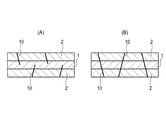
本発明の積層断熱材は、図1(A)、(B)に断面図にて示すように、ナノ無機粒子を圧縮成形してなる第1の成形体1と、曲げ強度が0.4MPa以上である第2の成形体2とを積層し、棒状または線状の連結部材10で連結したものである。ここで、本発明において、曲げ強度は、例えばJISA 9510に準じて測定されればよい。尚、同図の(A)、(B)は連結部材10による連結方法が異なるだけであり、(A)では第1の成形体1と第2の成形体2とを積層した高さ(全厚)よりも短い連結部材10を、所定間隔で、表裏面に交互に差し込んだ例を示しており、(B)は全厚と一致、もしくは若干短い連結部材10を所定間隔で差し込んだ例を示している。
The laminated heat insulating material of the present invention includes a first molded
ここで、ナノ無機粒子を圧縮成形してなる第1の成形体1と、曲げ強度が0.4MPa以上である第2の成形体2を積層するにあたって、例えば、公知の接着剤により固定するといった技術も考えられる。しかしながら、接着剤に含まれる水のような極性の大きな液体により、第1の成形体1に含まれる例えばフュームドシリカといったナノ無機粒子が急激に凝集してしまうため、第1の成形体1の表面に亀裂や陥没といった変形が発生することが懸念される。
Here, when laminating the first molded
また、第1の成形体1にはバインダーが含まれず、圧縮成形されているだけであり、強度が著しく弱く、表面が粉っぽいので、たとえ接着剤により固定できたとしても、接着剤が浸透した箇所と浸透していない箇所との界面ではがれやすく、わずかな力により簡単に剥離してしまう。
Further, the first molded
連結部材10としては、鉄やステンレス、アルミニウムといった金属やセラミックス、カーボン、樹脂、繊維強化プラスチック(以下、FRPともいう。)、ガラスからなる棒状体または線状体を用いることができ、成形したものでもよく、細線を拠って1本の太線としたものでもよい。中でも、高強度で弾性が高く、自身を通じて伝熱しないように熱伝導度が低いほど好ましく、カーボン製やガラス製、あるいはカーボンやガラスを含むことがより好ましい。カーボンやガラスを含む連結部材は、例えばカーボン繊維やガラス繊維を樹脂バインダーで固めたカーボン繊維製FRPロッドやガラス繊維製FRPロッドといったFRPロッドであってもよい。
As the connecting
連結部材10は、例えば所望形状の断面が連続した軸部を備えていればよい。軸部の断面形状は特に制限はないが、円形、楕円形、長方形、正方形といった形状が挙げられる。こうした軸部の太さ(最も長い径)には制限はないが、第1の成形体1と第2の成形体2とが剥がれないようにある程度の太さが必要であり、0.2〜4mmあればよく、好ましくは0.5〜2mm、より好ましくは0.8〜1.2mmである。また、連結部材10は、釘のように、軸部の一方に尖った先端部が形成されていてもよいし、もう一方に軸部の断面より断面積の大きい頭部が形成されていてもよい。
The
連結部材10の曲げ強度は、特に制限はないが、10MPa以上、好ましくは20MPa以上、さらに好ましくは30MPa以上であればよく、100MPa以上、500MPa以上であってもよい。こうした曲げ強度を備えていれば、第1の成形体1および第2の成形体2に差し込んだ際に不具合なく使用できる。
The bending strength of the connecting
連結部材10の密度、即ち単位面積当たりの本数には制限は無く、第1の成形体1と第2の成形体2とが積層状態を保持できればよく、必要以上に設けると断熱性能の低下を招くだけであることから、4〜120本/m2が適当であり、好ましくは、9〜90本/m2、さらに好ましくは、16〜80本/m2、より好ましくは、25〜75本/m2である。
There is no limit to the density of the connecting
また、連結部材10の差し込み様式は、図1に示すように第1の成形体1と第2の成形体2との界面に対し垂直にする他、図2に示すように斜めに差し込んでもよい。尚、傾斜角度θには制限はなく、例えば0°〜50°であればよく、好ましくは1°〜45°、より好ましくは5°〜30°であればよい。また、連結部材毎に傾斜角度が異なっていてもよい。また、連結部材10と連結部材10との間隔は、特に制限はないが、例えば10〜40mmであればよい。
Further, the connecting
また、図3に示すように、第2の成形体2の表面に凹部5を設け、凹部5に連結部材10を差し込んだ後、凹部5を充填材6で充填することもできる。これにより、棒状または線状の連結部材10が突出することがなく、加工作業や施工作業を安全に行うことができる。
In addition, as shown in FIG. 3, the
ナノ無機粒子としては、例えば、その一次粒子の平均直径が1〜100nmの範囲のものを用いることができる。ナノ無機粒子の一次粒子の平均直径は、好ましくは1〜50nmの範囲とすることができ、より好ましくは1〜25nmの範囲とすることができ、さらに好ましくは1〜15nmの範囲とすることができ、特に好ましくは1〜10nmの範囲とすることができる。なお、この平均直径は、ナノ粒子の真密度(g/m3)を「a」、ナノ無機粒子の比表面積(m2/g)を「S」とした場合に、式「D=6/(a×S)」で算出される換算粒子直径D(m)である。例えば、シリカの真密度は2.2×106g/m3であるため、比表面積が300m2/gであるシリカナノ粒子の平均直径(換算粒子径)は約9nmと算出される。 As the nano inorganic particles, for example, particles having an average primary particle diameter in the range of 1 to 100 nm can be used. The average diameter of the primary particles of the nano inorganic particles can be preferably in the range of 1 to 50 nm, more preferably in the range of 1 to 25 nm, and still more preferably in the range of 1 to 15 nm. Particularly preferably in the range of 1 to 10 nm. Note that this average diameter is expressed by the formula “D = 6 / when the true density (g / m 3 ) of the nanoparticles is“ a ”and the specific surface area (m 2 / g) of the nano-inorganic particles is“ S ”. (A × S) ”is a converted particle diameter D (m). For example, since the true density of silica is 2.2 × 10 6 g / m 3 , the average diameter (converted particle diameter) of silica nanoparticles having a specific surface area of 300 m 2 / g is calculated to be about 9 nm.
平均直径が100nm以下の一次粒子は、集合して二次粒子を形成することができる。このため、ナノ無機粒子を圧縮成形してなる第1の成形体は、ナノ無機粒子の二次粒子の集合体となる。そして、一次粒子の平均直径が小さいナノ粒子を用いることにより、二次粒子内に形成される空隙のサイズを低減することができる。さらに、この空隙のサイズを低減することにより、第1の成形体内における空気の対流を効果的に防止することができる。したがって、例えば、一次粒子の平均直径が10nm未満であるナノ粒子を圧縮成形してなる第1の成形体は、優れた断熱性を有することができる。 Primary particles having an average diameter of 100 nm or less can be aggregated to form secondary particles. For this reason, the 1st molded object formed by compression-molding a nano inorganic particle becomes an aggregate | assembly of the secondary particle of a nano inorganic particle. And the size of the space | gap formed in a secondary particle can be reduced by using the nanoparticle with a small average diameter of a primary particle. Furthermore, by reducing the size of the gap, air convection in the first molded body can be effectively prevented. Therefore, for example, the first molded body formed by compression molding nanoparticles having an average primary particle diameter of less than 10 nm can have excellent heat insulating properties.
ナノ無機粒子としては、例えば、シリカ、アルミナ、酸化チタン等の金属酸化物からなるナノ無機粒子を好ましく用いることができる。中でも、シリカからなるナノ粒子(シリカナノ粒子)を用いることにより、第1の成形体の断熱性を効果的に高めることができる。したがって、シリカナノ粒子を圧縮成形してなる第1の成形体は、特に優れた断熱性を有することができる。 As the nano inorganic particles, for example, nano inorganic particles made of a metal oxide such as silica, alumina, titanium oxide, etc. can be preferably used. Especially, the heat insulation of a 1st molded object can be effectively improved by using the nanoparticle (silica nanoparticle) which consists of silica. Therefore, the 1st molded object formed by compression-molding a silica nanoparticle can have the outstanding heat insulation.
シリカナノ粒子としては、気相法により製造される乾式シリカ(いわゆるフュームドシリカ)、又は液相法により製造される湿式シリカを好ましく用いることができる。乾式シリカとしては、その表面にシラノール基等の親水基を豊富に有する親水性フュームドシリカ、又は当該親水性フュームドシリカの表面に疎水化処理を施すことにより製造される疎水性フュームドシリカを用いることができる。疎水性フュームドシリカを圧縮成形してなる第1の成形体は、親水性フュームドシリカを圧縮成形してなる成形体に比べて、吸湿による断熱性の低下が起こりにくい。 As silica nanoparticles, dry silica (so-called fumed silica) produced by a gas phase method or wet silica produced by a liquid phase method can be preferably used. As dry silica, hydrophilic fumed silica having abundant hydrophilic groups such as silanol groups on its surface, or hydrophobic fumed silica produced by subjecting the surface of the hydrophilic fumed silica to hydrophobic treatment Can be used. The first molded body formed by compression-molding hydrophobic fumed silica is less susceptible to a decrease in heat insulation due to moisture absorption than a molded body formed by compression-molding hydrophilic fumed silica.
また、第1の成形体は、ナノ無機粒子に加えて、繊維材料をさらに含有することができる。第1の成形体が繊維材料を含有する場合、繊維材料は、例えば、第1の成形体内において、分散され、不規則に配向した繊維とすることができる。このような繊維としては、無機材料からなる繊維(無機繊維)、又は有機材料からなる繊維(有機繊維)を用いることができる。 In addition to the nano inorganic particles, the first molded body can further contain a fiber material. When the first molded body contains a fiber material, the fiber material can be, for example, dispersed and irregularly oriented fibers in the first molded body. As such a fiber, a fiber made of an inorganic material (inorganic fiber) or a fiber made of an organic material (organic fiber) can be used.
無機繊維としては、例えば、ガラス繊維、シリカ−アルミナ繊維、アルミナ繊維、シリカ繊維、ジルコニア繊維、アルカリケイ酸塩繊維等を用いることができる。有機繊維としては、例えば、アラミド繊維、カーボン繊維、ポリエステル繊維を用いることができる。これらの繊維は、複数種を併用してもよい。 As the inorganic fiber, for example, glass fiber, silica-alumina fiber, alumina fiber, silica fiber, zirconia fiber, alkali silicate fiber and the like can be used. As the organic fiber, for example, an aramid fiber, a carbon fiber, or a polyester fiber can be used. A plurality of these fibers may be used in combination.
また、第1の成形体に含有される繊維としては、例えば、繊維の直径(繊維径)が一定の長繊維(フィラメント)を所定長さに切断して製造されるチョップド繊維を用いることができる。具体的には、例えば、チョップドガラス繊維を用いることができる。チョップド繊維としては、例えば、平均繊維径が3〜15μmの範囲で平均長さが1〜20mmの範囲のものを用いることができ、好ましくは平均繊維径が6〜12μmの範囲で平均長さが3〜9mmの範囲のものを用いることができる。 Moreover, as a fiber contained in a 1st molded object, the chopped fiber manufactured by cut | disconnecting the long fiber (filament) with a fixed fiber diameter (fiber diameter) to predetermined length can be used, for example. . Specifically, for example, chopped glass fibers can be used. As the chopped fiber, for example, one having an average fiber diameter in the range of 3 to 15 μm and an average length in the range of 1 to 20 mm can be used, and preferably the average fiber diameter is in the range of 6 to 12 μm. The thing of the range of 3-9 mm can be used.
上述のような繊維を用いることにより、第1の成形体において、当該成形体を断裂させるような亀裂の発生を効果的に防止することができる。したがって、このような繊維を含有する第1の成形体は、その断熱性の低下を伴うことなく強度を向上させることができ、ハンドリング性を付与することができる。 By using the fibers as described above, it is possible to effectively prevent the occurrence of cracks that tear the molded body in the first molded body. Therefore, the 1st molded object containing such a fiber can improve intensity | strength without accompanying the fall of the heat insulation, and can provide handling property.
また、第1の成形体に含有されるナノ無機粒子と繊維との比率は、当該成形体が備えるべき特性(例えば、断熱性、耐熱性、低発塵性)に応じて適宜設定することができる。すなわち、第1の成形体は、例えば、ナノ無機粒子を50〜99重量%の範囲で含有するとともに繊維を1〜50重量%の範囲で含有することができ、好ましくはナノ無機粒子を70〜99重量%の範囲で含有するとともに繊維を1〜30重量%の範囲で含有することができ、より好ましくはナノ無機粒子を80〜99重量%の範囲で含有するとともに繊維を1〜20重量%の範囲で含有することができる。 In addition, the ratio of the nano-inorganic particles and the fibers contained in the first molded body can be appropriately set according to the characteristics (for example, heat insulating properties, heat resistance, low dust generation properties) that the molded body should have. it can. That is, the first molded body can contain, for example, nano-inorganic particles in a range of 50 to 99% by weight and fibers in a range of 1 to 50% by weight, preferably 70 to 70% of nano-inorganic particles. It can be contained in the range of 99% by weight and the fiber can be contained in the range of 1 to 30% by weight. More preferably, the nano-inorganic particles are contained in the range of 80 to 99% by weight and the fiber is 1 to 20% by weight It can contain in the range of.
繊維又はその集合体の熱伝導率は、ナノ無機粒子又はその集合体の熱伝導率に比べて大きいため、第1の成形体に含有される当該繊維の比率が増加すると、当該成形体の断熱性が低下する傾向がある。このため、第1の成形体は、上述のように、ナノ無機粒子を主成分として含有し、繊維を添加剤(副成分)として含有することが好ましい。第1の成形体に添加された繊維は、上述のとおり、当該成形体の断熱性を維持しつつ当該成形体にハンドリング性を付与することができる。 Since the thermal conductivity of the fiber or aggregate thereof is larger than the thermal conductivity of the nano-inorganic particles or aggregate thereof, the heat insulation of the molded body increases when the ratio of the fibers contained in the first molded body increases. Tend to decrease. For this reason, as above-mentioned, it is preferable that a 1st molded object contains a nano inorganic particle as a main component, and contains a fiber as an additive (subcomponent). As described above, the fibers added to the first molded body can impart handling properties to the molded body while maintaining the heat insulating property of the molded body.
このようなナノ無機粒子としてのフュームドシリカと無機繊維とを含む第1の成形体1として、例えば、日本マイクロサーム株式会社製「マイクロサーム」を市場から入手することもできる。
For example, “Microtherm” manufactured by Nippon Microtherm Co., Ltd. can be obtained from the market as the first molded
また、第1の成形体は、赤外線反射剤又は赤外線吸収剤を含有することができる。赤外線反射剤は、赤外線を反射する特性を有するものであれば特に限られず、例えば、炭化珪素、酸化チタン、酸化亜鉛、酸化鉄等の赤外線反射性材料を用いることができ、当該赤外線反射性材料の粒子(赤外線反射性粒子)を好ましく用いることができる。赤外線吸収剤は、赤外線を吸収する特性を有するものであれば特に限られず、例えば、カーボン、黒鉛等の黒色材料(赤外線吸収性材料)を用いることができ、当該赤外線吸収性材料の粒子(赤外線吸収性粒子)を好ましく用いることができる。こうした赤外線反射剤又は赤外線吸収剤の含有量は、例えば、5〜40重量%の範囲とすることができ、10〜30重量%の範囲とすることが好ましい。 Moreover, the 1st molded object can contain an infrared reflective agent or an infrared absorber. The infrared reflecting agent is not particularly limited as long as it has the property of reflecting infrared rays. For example, an infrared reflecting material such as silicon carbide, titanium oxide, zinc oxide, or iron oxide can be used. These particles (infrared reflective particles) can be preferably used. The infrared absorber is not particularly limited as long as it has the property of absorbing infrared rays. For example, a black material (infrared absorbing material) such as carbon or graphite can be used, and particles (infrared rays) of the infrared absorbing material can be used. Absorbent particles) can be preferably used. The content of such infrared reflector or infrared absorber can be, for example, in the range of 5 to 40% by weight, and preferably in the range of 10 to 30% by weight.
但し、ナノ無機粒子と繊維を併用すると、100℃近辺以下で使用する場合は熱伝導率が小さくなるが、100℃以上で使用する場合は赤外線反射剤又は赤外線吸収剤を添加することによって、熱伝導率が低くなり断熱性が向上する。断熱材は100℃以上で使用する場合が殆どであるため、通常は赤外線反射剤又は赤外線吸収剤を添加する。しかし、赤外線反射剤又は赤外線吸収剤の量が多いと強度が小さくなり、ハンドリング性が悪くなるため第1の成形体におけるナノ無機粒子の含有量を50質量%以上にすることが好ましく、60質量%以上とすることがより好ましい。残部は繊維及び赤外線反射剤又は赤外線吸収剤の少なくとも一方であるが、目的とする断熱性能に応じて適宜選択される。こうした場合の好ましい配合比率は、ナノ無機粒子50〜75質量%、無機繊維2〜15質量%、赤外線反射剤又は赤外線吸収剤10〜35質量%である。 However, when nano-inorganic particles and fibers are used in combination, the thermal conductivity decreases when used at around 100 ° C. or lower, but when used at 100 ° C. or higher, by adding an infrared reflector or infrared absorber, The conductivity is lowered and the heat insulation is improved. Since most of the heat insulating materials are used at 100 ° C. or higher, an infrared reflecting agent or an infrared absorbing agent is usually added. However, if the amount of the infrared reflecting agent or infrared absorbing agent is large, the strength is decreased and the handling property is deteriorated. Therefore, the content of the nano inorganic particles in the first molded body is preferably 50% by mass or more, and 60% by mass. % Or more is more preferable. The balance is at least one of fiber and infrared reflector or infrared absorber, and is appropriately selected according to the intended heat insulation performance. A preferable blending ratio in such a case is 50 to 75% by mass of nano-inorganic particles, 2 to 15% by mass of inorganic fibers, and 10 to 35% by mass of an infrared reflector or an infrared absorber.
また、第1の成形体1は、(1)ナノ無機粒子単独、(2)ナノ無機粒子と繊維、(3)ナノ無機粒子と繊維及び赤外線反射剤又は赤外線吸収剤の少なくとも一方を併用する場合ともバインダーを用いることなく、圧縮成形だけで成形体とする。そのため、第1の成形体1は著しく強度が劣るが、例えば、曲げ強度0.1〜0.35MPaであれば、ハンドリングできる。
Moreover, the 1st molded
第1の成形体1は、圧縮成形後の密度が100〜600kg/m3であることが好ましく、150〜400kg/m3であることがより好ましく、200〜300kg/m3であることがより好ましい。また、600℃における熱伝導率が0.1W/mK以下であることが好ましく、0.07W/mK以下であることがより好ましく、0.05W/mK以下であることがさらに好ましい。さらに、800℃における熱伝導率が0.1W/mK以下であることが好ましく、0.07W/mK以下であることがより好ましく、0.04W/mK以下であることがさらに好ましい。
The first molded
第1の成形体1は上記の如く構成されるが、ナノ無機粒子としてのフュームドシリカの粉落ちを更に抑制するために、図4に示すように、ガラスクロスやセラミックスクロス等の被覆材3で包囲することもでき、特にナノ無機粒子単独の場合に有効である。尚、被覆材3で包囲する場合は、先端が細く尖った連結部材10の方が差し込みしやすく、好ましい。
Although the 1st molded
一方、第2の成形体2は、断熱材全体としての取り扱い性や加工性、施工性などを高めるための部材であり、曲げ強度が0.4MPa以上、好ましくは0.8MPa以上、さらに好ましくは1.0MPa以上であれば、その材質には制限はない。例えば、耐熱性や断熱性が要求される場合には、無機繊維や珪酸カルシウム等を含む成形体を使用できる。
On the other hand, the 2nd molded
また、第2の成形体は、無機繊維を主成分とする無機繊維質成形体であってもよい。例えば、無機繊維50〜95質量%と、バインダー5〜30質量%と、無機粉末0〜30質量%、好ましくは5〜30質量部とを含む無機繊維質成形体であればよい。無機繊維としては、特に制限されず、例えば、ガラス繊維、グラスウール、ロックウール、アルミナ質繊維、ジルコニア質繊維、シリカ・アルミナ質繊維等が挙げられる。こうした無機繊維は、1種又は2種以上の組合わせのいずれでもよい。バインダーとしては、例えばコロイダルシリカ、アルミナゾル、ジルコニアゾル、チタニアゾルといった無機バインダーや、アクリル樹脂、澱粉、ポリアクリルアミドといった有機バインダーが挙げられる。こうしたバインダーは、1種又は2種以上の組合わせのいずれでもよい。 The second molded body may be an inorganic fibrous molded body containing inorganic fibers as a main component. For example, it may be an inorganic fibrous molded body containing 50 to 95% by mass of inorganic fibers, 5 to 30% by mass of a binder, and 0 to 30% by mass of inorganic powder, preferably 5 to 30 parts by mass. The inorganic fiber is not particularly limited, and examples thereof include glass fiber, glass wool, rock wool, alumina fiber, zirconia fiber, and silica / alumina fiber. These inorganic fibers may be one kind or a combination of two or more kinds. Examples of the binder include inorganic binders such as colloidal silica, alumina sol, zirconia sol, and titania sol, and organic binders such as acrylic resin, starch, and polyacrylamide. Such a binder may be one kind or a combination of two or more kinds.
無機繊維質成形体には、必要に応じて無機粉末を添加することができる。無機粉末を添加することにより、耐火性が高くなる。こうした無機粉末としては、例えば、シリカ、アルミナ、ムライト、窒化ケイ素、炭化ケイ素、チタニア、ジルコニア等のセラミックス粉末、カーボンブラック等の炭素粉末等が挙げられ、これらのうち、好ましくはシリカ、アルミナ、窒化ケイ素、炭化ケイ素、ムライト、チタニア、ジルコニア等のセラミックス粉末、カーボンブラック等の炭素粉末であり、特に好ましくはシリカ、アルミナ、窒化ケイ素、炭化ケイ素等のセラミックス粉末である。こうした無機粉末は、1種又は2種以上の組合わせのいずれでもよい。 An inorganic powder can be added to the inorganic fibrous molded body as necessary. By adding inorganic powder, fire resistance is increased. Examples of such inorganic powders include ceramic powders such as silica, alumina, mullite, silicon nitride, silicon carbide, titania and zirconia, and carbon powders such as carbon black. Among these, silica, alumina, and nitride are preferable. Ceramic powders such as silicon, silicon carbide, mullite, titania and zirconia, and carbon powders such as carbon black, particularly preferably ceramic powders such as silica, alumina, silicon nitride and silicon carbide. These inorganic powders may be one kind or a combination of two or more kinds.
無機繊維質成形体の密度は特に制限はないが、100〜700kg/m3であればよく、150〜400kg/m3であることが好ましく、200〜300kg/m3であることがより好ましい。また、600℃における熱伝導率が0.3W/mK以下であることが好ましく、0.2W/mK以下であることがより好ましく、0.1W/mK以下であることがさらに好ましい。 Is not particularly limited density of the inorganic fibrous molded body may be a 100~700kg / m 3, it is preferably 150~400kg / m 3, more preferably 200~300kg / m 3. Further, the thermal conductivity at 600 ° C. is preferably 0.3 W / mK or less, more preferably 0.2 W / mK or less, and further preferably 0.1 W / mK or less.
こうした無機繊維質成形体は、優れた断熱性を備え、単独で断熱材としても用いられ、例えば、ニチアス株式会社製「ファインフレックス1300ハードボード」、「RFボード」などを市場から入手することもできる。 Such an inorganic fiber molded body has excellent heat insulating properties and is used alone as a heat insulating material. For example, “Fineflex 1300 Hardboard”, “RF Board” manufactured by NICHIAS Corporation may be obtained from the market. it can.
また、第2の成形体は、珪酸カルシウムを主成分とする珪酸カルシウム質成形体であってもよい。本発明においては、珪酸カルシウムは、珪酸質原料(SiO2)とカルシウム原料(CaO)を水の存在下で水熱反応せしめて生成した化合物であってもよい。その結晶として特に制限されないが、例えば、ゾノトライト結晶、トバモライト結晶、不定形C−S−H結晶等が挙げられる。特にゾノトライト結晶からなる成形体は軽量で比強度が非常に大きく、耐熱性と断熱性に優れているため好ましい。なお、こうした結晶の有無は、X線回析により各種結晶に特有の回析ピークが得られるため、第2の成形体の表面をX線回析すれば容易に判断することができる。 Further, the second molded body may be a calcium silicate molded body mainly composed of calcium silicate. In the present invention, the calcium silicate may be a compound produced by a hydrothermal reaction of a siliceous raw material (SiO 2 ) and a calcium raw material (CaO) in the presence of water. Although it does not restrict | limit especially as the crystal | crystallization, For example, a zonotolite crystal | crystallization, a tobermorite crystal | crystallization, an amorphous CSH crystal | crystallization etc. are mentioned. In particular, a molded body made of zonotlite crystals is preferable because it is lightweight, has a very high specific strength, and is excellent in heat resistance and heat insulation. In addition, since the diffraction peak peculiar to various crystals is obtained by X-ray diffraction, the presence or absence of such a crystal can be easily determined by X-ray diffraction on the surface of the second compact.
珪酸カルシウム質成形体は、珪酸カルシウム以外に、セメントや石膏といった補強材や、タルクや珪藻土、フライアッシュといった充填材、ガラス繊維やセラミック繊維、アルミナ繊維、ワラストナイト、パルプ、ポリプロピレン繊維、アラミド繊維、カーボン繊維といった補強繊維、マイクロシリカやパーライト、シラスバルーン、ガラスバルーンといった軽量骨材等が必要に応じて任意に添加配合されていてもよい。また、未反応のケイ酸質原料や石灰質原料を含んでいてもよい。 In addition to calcium silicate, calcium silicate moldings are made of reinforcing materials such as cement and gypsum, fillers such as talc, diatomaceous earth, and fly ash, glass fibers and ceramic fibers, alumina fibers, wollastonite, pulp, polypropylene fibers, and aramid fibers. Further, reinforcing fibers such as carbon fibers, lightweight aggregates such as microsilica, perlite, shirasu balloon, and glass balloon may be optionally added and blended as necessary. Moreover, the unreacted siliceous raw material and the calcareous raw material may be included.
こうした珪酸カルシウム質成形体は、例えば、珪酸カルシウム100質量部に対して、補強材0〜20質量部、好ましくは10〜20質量部、充填材0〜20質量部、好ましくは0〜10質量部、補強繊維0〜20質量部、好ましくは5〜10質量部、軽量骨材0〜20質量部、好ましくは5〜10質量部を含む珪酸カルシウム質成形体であればよい。 Such a calcium silicate compact is, for example, 0 to 20 parts by mass, preferably 10 to 20 parts by mass, and 0 to 20 parts by mass of a filler, preferably 0 to 10 parts by mass with respect to 100 parts by mass of calcium silicate. The calcium silicate molded body may contain 0 to 20 parts by mass of reinforcing fibers, preferably 5 to 10 parts by mass, and 0 to 20 parts by mass of lightweight aggregate, preferably 5 to 10 parts by mass.
こうした珪酸カルシウム質成形体の密度は特に制限はないが、50〜900kg/m3であればよく、80〜600kg/m3であることが好ましく、100〜400kg/m3であることがより好ましい。また、600℃における熱伝導率が0.2W/mK以下であることが好ましく、0.18W/mK以下であることがより好ましく、0.16W/mK以下であることがさらに好ましい。 Density of such calcium silicate electrolyte molded body is not particularly limited, may be a 50~900kg / m 3, it is preferably 80~600kg / m 3, more preferably 100~400kg / m 3 . Further, the thermal conductivity at 600 ° C. is preferably 0.2 W / mK or less, more preferably 0.18 W / mK or less, and further preferably 0.16 W / mK or less.
こうした珪酸カルシウム質成形体は、軽量で、高強度であり、断熱性や耐熱性にも優れるため好ましく、例えば、ニチアス株式会社製「キャスライトH」、「スーパーテンプボード」などを市場から入手することもできる。 Such a calcium silicate molded body is preferable because it is lightweight, high in strength, and excellent in heat insulation and heat resistance. For example, “Casslite H”, “Super Tempboard” manufactured by NICHIAS CORPORATION are obtained from the market. You can also.
また、第2の成形体2は、使用温度が50℃以下といった比較的低温領域であれば、例えば、ポリウレタンフォーム、ポリエチレンフォーム、ポリプロピレンフォームなどといった硬質発泡樹脂製成形体を使用することができる。こうした硬質発泡樹脂製成形体は、例えば、ニチアス株式会社製「フォームナートボードTN」などを市場から入手することもできる。
Further, the second molded
尚、第1の成形体1及び第2の成形体2のそれぞれの厚さ、断熱材の全厚は、目的とする断熱性能に応じて適宜選択される。例えば、第1の成形体1の厚さは、5〜100mmであればよく、好ましくは5〜70mm、より好ましくは10〜40mmであり、20〜30mmであってもよい。第2の成形体2の厚さは、5〜100mmであればよく、好ましくは5〜70mm、より好ましくは10〜40mmであり、20〜30mmであってもよい。断熱材の全厚は、10〜200mmであればよく、好ましくは10〜140mm、より好ましくは40〜90mmであり、60〜80mmであってもよい。また、熱源に対し、第1の成形体1を向けて配置してもよいし、第2の成形体2を向けて配置してもよいが、第1の成形体1は耐熱性が低いため、炉のライニング材等のように高温の熱源に対しては第2の成形体2を熱源側にする必要がある。
In addition, each thickness of the 1st molded
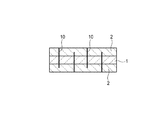
本発明は種々の変更が可能であり、例えば、図5(A)、(B)に示すように第1の成形体の両面に第2の成形体が積層された3層構造の断熱材とすることができる。3層にする場合、図示のように第1の成形体1を2枚の第2の成形体2,2で挟んだサンドイッチ構造とすることにより、第1の成形体1からのナノ無機粒子の粉落ちを抑制することができる。
The present invention can be variously modified. For example, as shown in FIGS. 5A and 5B, a three-layer heat insulating material in which a second molded body is laminated on both surfaces of the first molded body, can do. In the case of three layers, a sandwich structure in which the first molded
また、図6(A)、(B)に示すように、連結部材10を斜め方向から差し込んでもよい。尚、図2に示したように、傾斜角度θを選択できる。また、3層構造とする場合、図7に示すように、連結部材10を一方の第2の成形体2から他方の第2の成形体2に到達するように差し込んでもよい。また、連結部材10と連結部材10との間隔は、特に制限はないが、例えば10〜40mmであればよい。
Further, as shown in FIGS. 6A and 6B, the connecting
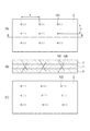
更には、図8((A)は上面図、(B)はAA断面図)に示すように、一対の連結部材10A、10Bを断熱材の厚さ方向において接触または非接触で交差させ(図の例では非接触)、列状に差し込むことにより、3層構造をより効果的に連結することができる。このとき、一対の連結部材10A、10Bの間隔aは3〜50mm、好ましくは5〜10mm、一対の連結部材10A、10Bからなる列間の紙面水平方向の間隔bは50〜500mm、好ましくは100〜300mm、一対の連結部材10A、10Bの間隔cは0〜30mm、好ましくは3〜10mm、一対の連結部材10A、10Bからなる列間の紙面垂直方向の間隔dは50〜500mm、好ましくは100〜200mmが適当であるが、断熱材の面積や厚さにより、適宜選択することができる。また、連結部材10A,10Bは、図示のように互いに平行である必要はなく、傾斜していてもよい。
Furthermore, as shown in FIG. 8 ((A) is a top view and (B) is an AA cross-sectional view), a pair of connecting
更にまた、図9((A)は上面図、(B)はAA断面図、(C)は下面図)に示すように、連結部材10C、10Dの一方(ここでは10C)を上面から差し込み、他方(ここでは10D)を下面から差し込むとともに、一対の連結部材10C、10Dを断熱材の厚さ方向において接触または非接触(図の例では非接触)で交差させ、列状に差し込むことにより、図8と同様に3層構造をより効果的に連結することができる。このとき、連結部材10Cまたは10Dの長手方向の間隔eは5〜40mm、好ましくは10〜30mm、幅方向の間隔fは50〜500mm、好ましくは100〜200mmが適当であるが、断熱材の面積や厚さにより、適宜選択することができる。また、連結部材10C,10Dは、図示のように互いに平行である必要はなく、傾斜していてもよい。
Furthermore, as shown in FIG. 9 ((A) is a top view, (B) is an AA cross-sectional view, and (C) is a bottom view), one of the connecting
上記において、図3に示したように、第2の成形体2に凹部5を設けて連結部材10を埋め込むこともできる。
In the above, as shown in FIG. 3, the connecting
また、何れも図示は省略するが、第1の成形体1を2層重ねてより断熱性を高め、第2の成形体2を添設することもできる。必要により、4層以上の多層にすることもできる。更には、平板状の他に、湾曲させることもでき、半円筒にすることもできる。
Moreover, although illustration is abbreviate | omitted in any case, two layers of the 1st molded
1 第1の成形体
2 第2の成形体
3 被覆材
5 凹部
6 充填材
10 連結部材
DESCRIPTION OF
Claims (6)
The method for manufacturing a heat insulating material according to claim 5, wherein the connecting member is inserted perpendicularly or inclined with respect to the interface between the first molded body and the second molded body.
Priority Applications (5)
| Application Number | Priority Date | Filing Date | Title |
|---|---|---|---|
| JP2010187403A JP5351112B2 (en) | 2009-09-02 | 2010-08-24 | Insulation |
| TW99129632A TW201109169A (en) | 2009-09-02 | 2010-09-02 | Thermal insulation material |
| KR1020100086123A KR20110025148A (en) | 2009-09-02 | 2010-09-02 | insulator |
| US12/874,393 US20110052897A1 (en) | 2009-09-02 | 2010-09-02 | Thermal insulation material |
| CN2010102732449A CN102003595A (en) | 2009-09-02 | 2010-09-02 | Thermal insulation material |
Applications Claiming Priority (3)
| Application Number | Priority Date | Filing Date | Title |
|---|---|---|---|
| JP2009202742 | 2009-09-02 | ||
| JP2009202742 | 2009-09-02 | ||
| JP2010187403A JP5351112B2 (en) | 2009-09-02 | 2010-08-24 | Insulation |
Publications (2)
| Publication Number | Publication Date |
|---|---|
| JP2011073959A true JP2011073959A (en) | 2011-04-14 |
| JP5351112B2 JP5351112B2 (en) | 2013-11-27 |
Family
ID=43625353
Family Applications (1)
| Application Number | Title | Priority Date | Filing Date |
|---|---|---|---|
| JP2010187403A Expired - Fee Related JP5351112B2 (en) | 2009-09-02 | 2010-08-24 | Insulation |
Country Status (5)
| Country | Link |
|---|---|
| US (1) | US20110052897A1 (en) |
| JP (1) | JP5351112B2 (en) |
| KR (1) | KR20110025148A (en) |
| CN (1) | CN102003595A (en) |
| TW (1) | TW201109169A (en) |
Cited By (10)
| Publication number | Priority date | Publication date | Assignee | Title |
|---|---|---|---|---|
| JP2012250882A (en) * | 2011-06-03 | 2012-12-20 | Asahi Kasei Chemicals Corp | Molded article, wrapped article, and method for manufacturing molded article |
| JP2013001587A (en) * | 2011-06-14 | 2013-01-07 | Asahi Kasei Chemicals Corp | Powder, molded body, wrapped body, and method for producing powder |
| JP2014062645A (en) * | 2012-08-31 | 2014-04-10 | Nichias Corp | Heat insulation unit, manufacturing method of heat insulation unit and heating furnace |
| KR20140073486A (en) * | 2011-07-18 | 2014-06-16 | 릴코 매뉴팩쳐링 컴퍼니 인코포레이티드 | Method and system for reinforced pipe insulation |
| JP2014228035A (en) * | 2013-05-21 | 2014-12-08 | イソライト工業株式会社 | Fireproof heat insulation material and manufacturing method |
| JP2017215014A (en) * | 2016-06-02 | 2017-12-07 | パナソニックIpマネジメント株式会社 | Heat insulating material and apparatus using the same |
| JP2018204781A (en) * | 2017-06-09 | 2018-12-27 | 三菱重工業株式会社 | Multilayer heat insulation material |
| JP2020076504A (en) * | 2020-01-29 | 2020-05-21 | ニチアス株式会社 | Laminate heat insulating material and method for manufacturing the same |
| JP2022125585A (en) * | 2021-02-17 | 2022-08-29 | 住友理工株式会社 | Heat insulation material |
| JP2024142871A (en) * | 2023-03-30 | 2024-10-11 | イソライト工業株式会社 | Heat insulating sheet and its manufacturing method |
Families Citing this family (9)
| Publication number | Priority date | Publication date | Assignee | Title |
|---|---|---|---|---|
| KR101308491B1 (en) * | 2011-04-18 | 2013-09-23 | 박수규 | Solar heat and Solar Cell Convergence Systemn Including Hydrogen, Fuel Cell and Insulator Producing Devices by Waste Pyrolysis |
| AT511928A1 (en) | 2011-08-24 | 2013-03-15 | Kiss Johann | ARRANGEMENT OF A FIBROUS WORKPIECE IN A LAYERED WORKPIECE |
| FR2980732B1 (en) * | 2011-10-04 | 2013-10-11 | Airbus Operations Sas | METHOD AND DEVICE FOR WELDING A THERMOPLASTIC STIFFENER |
| CN103953822B (en) * | 2014-04-20 | 2015-12-30 | 莱州明发隔热材料有限公司 | A kind of manufacture method of high-temperature energy-conservation type eakleite composite heat-insulating shield |
| US10041724B2 (en) | 2015-12-08 | 2018-08-07 | Whirlpool Corporation | Methods for dispensing and compacting insulation materials into a vacuum sealed structure |
| WO2018150518A1 (en) | 2017-02-16 | 2018-08-23 | ニチアス株式会社 | Thermally conductive cover for piping system, piping system heating device, manufacturing method and attachment method for thermally conductive cover, and manufacturing method and attachment method for heating device |
| CN112047744B (en) * | 2020-07-17 | 2022-10-04 | 北京盈德化工有限公司 | Heat-insulating material and preparation method and application thereof |
| CN113024267A (en) * | 2021-04-12 | 2021-06-25 | 武汉科技大学 | Nano heat-insulating material and preparation method thereof |
| KR102860286B1 (en) * | 2022-10-04 | 2025-09-17 | 주식회사 아이원 | Wet adiabatic materials manufacturing method without binder and adiabatic materials prepared therefrom |
Citations (5)
| Publication number | Priority date | Publication date | Assignee | Title |
|---|---|---|---|---|
| JPS61166827U (en) * | 1985-04-08 | 1986-10-16 | ||
| JPH08121683A (en) * | 1994-10-18 | 1996-05-17 | Kubota Corp | Filler for vacuum heat insulator and method for manufacturing vacuum heat insulator |
| JP2005036975A (en) * | 2003-06-27 | 2005-02-10 | Matsushita Electric Ind Co Ltd | Insulating material, manufacturing method thereof, and equipment using the insulating material |
| JP2008194974A (en) * | 2007-02-14 | 2008-08-28 | Nichias Corp | Insulating material and manufacturing method thereof |
| JP2009041649A (en) * | 2007-08-08 | 2009-02-26 | Panasonic Corp | Vacuum heat insulating material and method for manufacturing vacuum heat insulating material |
Family Cites Families (9)
| Publication number | Priority date | Publication date | Assignee | Title |
|---|---|---|---|---|
| US5102723A (en) * | 1989-11-13 | 1992-04-07 | Pepin John N | Structural sandwich panel with energy-absorbing material pierced by rigid rods |
| US5470649A (en) * | 1994-06-24 | 1995-11-28 | The United States Of America As Represented By The Adminstrator Of The National Aeronautics And Space Administration | Composite with through the thickness reinforcement |
| US5876652A (en) * | 1996-04-05 | 1999-03-02 | The Boeing Company | Method for improving pulloff strength in pin-reinforced sandwich structure |
| ITMI20011458A1 (en) * | 2001-07-09 | 2003-01-09 | Getters Spa | SYSTEM FOR THE THERMAL INSULATION OF TUBULAR BODIES |
| CN100402913C (en) * | 2004-05-11 | 2008-07-16 | 岑保卫 | Combined type heat preservation pipeline covering |
| CN100537215C (en) * | 2005-04-22 | 2009-09-09 | 海尔集团公司 | Aerospace thermal-insulated plate and its preparing process |
| JP5077659B2 (en) * | 2007-07-20 | 2012-11-21 | ニチアス株式会社 | Catalytic converter and holding material for catalytic converter |
| EP2045505A1 (en) * | 2007-10-02 | 2009-04-08 | Logstor A/S | Bendable pre-insulated pipeline assembly |
| CN201193758Y (en) * | 2007-12-27 | 2009-02-11 | 大庆石油学院 | Electrochemical alloy nano-coating anti-corrosion insulation pipe |
-
2010
- 2010-08-24 JP JP2010187403A patent/JP5351112B2/en not_active Expired - Fee Related
- 2010-09-02 KR KR1020100086123A patent/KR20110025148A/en not_active Ceased
- 2010-09-02 CN CN2010102732449A patent/CN102003595A/en active Pending
- 2010-09-02 US US12/874,393 patent/US20110052897A1/en not_active Abandoned
- 2010-09-02 TW TW99129632A patent/TW201109169A/en unknown
Patent Citations (5)
| Publication number | Priority date | Publication date | Assignee | Title |
|---|---|---|---|---|
| JPS61166827U (en) * | 1985-04-08 | 1986-10-16 | ||
| JPH08121683A (en) * | 1994-10-18 | 1996-05-17 | Kubota Corp | Filler for vacuum heat insulator and method for manufacturing vacuum heat insulator |
| JP2005036975A (en) * | 2003-06-27 | 2005-02-10 | Matsushita Electric Ind Co Ltd | Insulating material, manufacturing method thereof, and equipment using the insulating material |
| JP2008194974A (en) * | 2007-02-14 | 2008-08-28 | Nichias Corp | Insulating material and manufacturing method thereof |
| JP2009041649A (en) * | 2007-08-08 | 2009-02-26 | Panasonic Corp | Vacuum heat insulating material and method for manufacturing vacuum heat insulating material |
Cited By (16)
| Publication number | Priority date | Publication date | Assignee | Title |
|---|---|---|---|---|
| JP2012250882A (en) * | 2011-06-03 | 2012-12-20 | Asahi Kasei Chemicals Corp | Molded article, wrapped article, and method for manufacturing molded article |
| JP2013001587A (en) * | 2011-06-14 | 2013-01-07 | Asahi Kasei Chemicals Corp | Powder, molded body, wrapped body, and method for producing powder |
| US10252490B2 (en) | 2011-07-18 | 2019-04-09 | Rilco Manufacturing Company, Inc. | Method and system for reinforced pipe insulation |
| JP2014522951A (en) * | 2011-07-18 | 2014-09-08 | リルコ マニュファクチャリング カンパニー,インコーポレイテッド | Method and system for reinforced pipe insulation |
| KR20140073486A (en) * | 2011-07-18 | 2014-06-16 | 릴코 매뉴팩쳐링 컴퍼니 인코포레이티드 | Method and system for reinforced pipe insulation |
| KR102184357B1 (en) * | 2011-07-18 | 2020-11-30 | 릴코 매뉴팩쳐링 컴퍼니 인코포레이티드 | Method and system for reinforced pipe insulation |
| JP2014062645A (en) * | 2012-08-31 | 2014-04-10 | Nichias Corp | Heat insulation unit, manufacturing method of heat insulation unit and heating furnace |
| JP2014228035A (en) * | 2013-05-21 | 2014-12-08 | イソライト工業株式会社 | Fireproof heat insulation material and manufacturing method |
| JP2021050825A (en) * | 2016-06-02 | 2021-04-01 | パナソニックIpマネジメント株式会社 | Heat insulating material and apparatus using the same |
| JP2017215014A (en) * | 2016-06-02 | 2017-12-07 | パナソニックIpマネジメント株式会社 | Heat insulating material and apparatus using the same |
| JP2018204781A (en) * | 2017-06-09 | 2018-12-27 | 三菱重工業株式会社 | Multilayer heat insulation material |
| JP2020076504A (en) * | 2020-01-29 | 2020-05-21 | ニチアス株式会社 | Laminate heat insulating material and method for manufacturing the same |
| JP7163330B2 (en) | 2020-01-29 | 2022-10-31 | ニチアス株式会社 | LAMINATED INSULATION MATERIAL AND METHOD FOR MANUFACTURING THE SAME |
| JP2022125585A (en) * | 2021-02-17 | 2022-08-29 | 住友理工株式会社 | Heat insulation material |
| JP2024142871A (en) * | 2023-03-30 | 2024-10-11 | イソライト工業株式会社 | Heat insulating sheet and its manufacturing method |
| JP7629953B2 (en) | 2023-03-30 | 2025-02-14 | イソライト工業株式会社 | Heat insulating sheet and its manufacturing method |
Also Published As
| Publication number | Publication date |
|---|---|
| JP5351112B2 (en) | 2013-11-27 |
| CN102003595A (en) | 2011-04-06 |
| KR20110025148A (en) | 2011-03-09 |
| US20110052897A1 (en) | 2011-03-03 |
| TW201109169A (en) | 2011-03-16 |
Similar Documents
| Publication | Publication Date | Title |
|---|---|---|
| JP5351112B2 (en) | Insulation | |
| Ge et al. | Overview of aerogels for thermal insulation | |
| Chang et al. | Superelastic carbon aerogels: an emerging material for advanced thermal protection in extreme environments | |
| WO2019088195A1 (en) | Heat insulation sheet for battery pack, and battery pack | |
| JP6592050B2 (en) | Composite material of airgel and fiber vat | |
| JP5651714B2 (en) | Insulating material using expanded perlite of closed cell | |
| JP4860005B1 (en) | Insulating material and manufacturing method thereof | |
| Okada et al. | Water-retention properties of porous ceramics prepared from mixtures of allophane and vermiculite for materials to counteract heat island effects | |
| Zhang et al. | Preparation of porous mullite ceramics composed entirely of overlapping and interlocking mullite whiskers through whisker in-situ growth | |
| US10253917B2 (en) | Insulation material and method of manufacturing same | |
| CN104745102B (en) | Nano heat-insulating tackifier and preparation method thereof | |
| CN107954742A (en) | Light porous refractory brick and preparation method thereof | |
| JP3578172B1 (en) | Vacuum insulation, refrigerators and refrigerators | |
| JP6418733B2 (en) | Heat insulation unit, method for manufacturing heat insulation unit and heating furnace | |
| CN108822873A (en) | A kind of Performances of Novel Nano-Porous meter level micropore heat-barrier material and preparation method thereof | |
| CN1207242C (en) | Formed heat insulator | |
| CN108928057A (en) | A kind of fibre-reinforced flexible aerosil | |
| Xu et al. | Hierarchical alumina fiber-reinforced silica aerogel with superior mechanical robustness and thermal shielding for extreme environments | |
| CN107954740A (en) | Corrosion-resistant micropore alumine light fire brick and preparation method thereof | |
| CN121107825A (en) | A sound-insulating porous ceramic tile and its preparation method | |
| CN107954746A (en) | Micropore flint clay light fire brick and preparation method thereof | |
| Fu et al. | A compressible, highly elastic anisotropic SiC/SiO2 composite aerogel for thermal-insulated building materials | |
| RU95592U1 (en) | MULTI-LAYER HEAT-INSULATING MATERIAL | |
| JP4679324B2 (en) | Insulation | |
| WO2011115353A1 (en) | Alumina bonded unshaped refractory and manufacturing method thereof |
Legal Events
| Date | Code | Title | Description |
|---|---|---|---|
| A621 | Written request for application examination |
Free format text: JAPANESE INTERMEDIATE CODE: A621 Effective date: 20121010 |
|
| A871 | Explanation of circumstances concerning accelerated examination |
Free format text: JAPANESE INTERMEDIATE CODE: A871 Effective date: 20121109 |
|
| A975 | Report on accelerated examination |
Free format text: JAPANESE INTERMEDIATE CODE: A971005 Effective date: 20121206 |
|
| A131 | Notification of reasons for refusal |
Free format text: JAPANESE INTERMEDIATE CODE: A131 Effective date: 20121218 |
|
| A521 | Request for written amendment filed |
Free format text: JAPANESE INTERMEDIATE CODE: A523 Effective date: 20130212 |
|
| A02 | Decision of refusal |
Free format text: JAPANESE INTERMEDIATE CODE: A02 Effective date: 20130416 |
|
| A521 | Request for written amendment filed |
Free format text: JAPANESE INTERMEDIATE CODE: A523 Effective date: 20130702 |
|
| A911 | Transfer to examiner for re-examination before appeal (zenchi) |
Free format text: JAPANESE INTERMEDIATE CODE: A911 Effective date: 20130709 |
|
| TRDD | Decision of grant or rejection written | ||
| A01 | Written decision to grant a patent or to grant a registration (utility model) |
Free format text: JAPANESE INTERMEDIATE CODE: A01 Effective date: 20130730 |
|
| A61 | First payment of annual fees (during grant procedure) |
Free format text: JAPANESE INTERMEDIATE CODE: A61 Effective date: 20130822 |
|
| R150 | Certificate of patent or registration of utility model |
Ref document number: 5351112 Country of ref document: JP Free format text: JAPANESE INTERMEDIATE CODE: R150 Free format text: JAPANESE INTERMEDIATE CODE: R150 |
|
| R250 | Receipt of annual fees |
Free format text: JAPANESE INTERMEDIATE CODE: R250 |
|
| R250 | Receipt of annual fees |
Free format text: JAPANESE INTERMEDIATE CODE: R250 |
|
| R250 | Receipt of annual fees |
Free format text: JAPANESE INTERMEDIATE CODE: R250 |
|
| LAPS | Cancellation because of no payment of annual fees |