JP2011069578A - Bathroom dryer - Google Patents
Bathroom dryer Download PDFInfo
- Publication number
- JP2011069578A JP2011069578A JP2009222791A JP2009222791A JP2011069578A JP 2011069578 A JP2011069578 A JP 2011069578A JP 2009222791 A JP2009222791 A JP 2009222791A JP 2009222791 A JP2009222791 A JP 2009222791A JP 2011069578 A JP2011069578 A JP 2011069578A
- Authority
- JP
- Japan
- Prior art keywords
- air
- bathroom
- circulation
- exhaust
- port
- Prior art date
- Legal status (The legal status is an assumption and is not a legal conclusion. Google has not performed a legal analysis and makes no representation as to the accuracy of the status listed.)
- Granted
Links
Images

Classifications
-
- Y—GENERAL TAGGING OF NEW TECHNOLOGICAL DEVELOPMENTS; GENERAL TAGGING OF CROSS-SECTIONAL TECHNOLOGIES SPANNING OVER SEVERAL SECTIONS OF THE IPC; TECHNICAL SUBJECTS COVERED BY FORMER USPC CROSS-REFERENCE ART COLLECTIONS [XRACs] AND DIGESTS
- Y02—TECHNOLOGIES OR APPLICATIONS FOR MITIGATION OR ADAPTATION AGAINST CLIMATE CHANGE
- Y02P—CLIMATE CHANGE MITIGATION TECHNOLOGIES IN THE PRODUCTION OR PROCESSING OF GOODS
- Y02P70/00—Climate change mitigation technologies in the production process for final industrial or consumer products
- Y02P70/10—Greenhouse gas [GHG] capture, material saving, heat recovery or other energy efficient measures, e.g. motor control, characterised by manufacturing processes, e.g. for rolling metal or metal working
Abstract
Description
本発明は、浴室乾燥機に関する。 The present invention relates to a bathroom dryer.
浴室内の空気を吸引して浴室内を乾燥させることが可能な浴室乾燥機として、下記特許文献1に記載されているような浴室乾燥機が提案されている。下記特許文献1に記載の浴室乾燥機は、排気ファンと吸気ファンと熱交換器とを備えているものである。背景技術の理解を容易にするため、下記特許文献1に記載の浴室乾燥機の概念的な構成図を図11に示す。 As a bathroom dryer capable of sucking air in a bathroom and drying the inside of the bathroom, a bathroom dryer as described in Patent Document 1 has been proposed. The bathroom dryer described in Patent Literature 1 below includes an exhaust fan, an intake fan, and a heat exchanger. In order to facilitate understanding of the background art, FIG. 11 shows a conceptual configuration diagram of a bathroom dryer described in Patent Document 1 below.
図11に示す浴室乾燥機80は、本体800に、浴室と連通する浴室側吸込口801と、浴室側リターン空気吸込口802と、浴室側吐出口803と、室外と連通する室外側吸込口804と、室外側吐出口805とを設けている。本体800内には、浴室側吸込口801より室外側吐出口805に至る排気通風路806と、室外側吸込口804より浴室側吐出口803に至る給気通風路807を形成している。給気通風路807に、浴室側リターン空気吸込口802を連通させるとともに、ヒータ808及び給気用ファンモータ809を設けている。排気通風路806には、排気用ファンモータ810を設けている。給気通風路807と排気通風路806の交差する所には、熱交換器811を設けている。給気通風路807の熱交換器811の風下側と、排気通風路806の熱交換器811の風上側とを結ぶ連通路812を有し、連通路812の給気通風路807側に開閉ダンパ813と、排気通風路806側に開閉ダンパ814とを設けている。
A
図11に示す浴室乾燥機80は、このような構成を備えることで、次のような運転モードを実行することができる。第一の運転モードは、熱回収を行いながら温風乾燥を行うモードである。具体的には、給気用ファンモータ809と排気用ファンモータ810を運転し、浴室側吸込口801より浴室空気が入り、排気用ファンモータ810を通って熱交換器811を通り熱交換を行なったのち、室外側吐出口805より室外へ排出される。一方室外空気は、室外側吸込口804より入り、熱交換器811を通って熱交換を行なったのち、浴室側リターン空気吸込口802より入る空気と合流して、給気用ファンモータ809を通り、ヒータ808で暖められた上で浴室側吐出口803より浴室内へ給気される。
The
第二の運転モードは、熱交換を行わずに排気又は給気を行うモードである。具体的には、排気用ファンモータ810だけを運転すると、浴室側吸込口801より浴室空気が入り、排気用ファンモータ810を通って熱交換器811中を通り、室外側吐出口805より室外へ排出される。次にヒータ808を切り給気用ファンモータ809だけを運転すると、室外側吸込口804より室外空気が入り、熱交換器811中を通って、浴室側リターン空気吸込口802より入る空気と合流して、給気用ファンモータ809を通り、浴室側吐出口803より浴室内へ給気される。
The second operation mode is a mode for exhausting or supplying air without performing heat exchange. Specifically, when only the
第三の運転モードは、空気を循環させて暖房を行うモードである。具体的には、開閉ダンパ813,814を開き、給気用ファンモータ809と排気用ファンモータ810を運転すると、浴室側吸込口801より浴室空気が入り、排気用ファンモータ810を通って連通路812を介して浴室側リターン空気吸込口802より入る空気と合流し、給気用ファンモータ809を通り、浴室空気はヒータ808で暖められた上で浴室側吐出口803より浴室内へ給気される。
The third operation mode is a mode in which heating is performed by circulating air. Specifically, when the open /
上記特許文献1に記載の浴室乾燥機では、熱交換を行わずに排気又は給気を行うモードである第二の運転モードの際には排気用ファンモータ810又は給気用ファンモータ809を選択的に駆動させる。しかしながら、熱回収を行いながら温風乾燥を行うモードである第一の運転モードの際や、空気を循環させて暖房を行うモードである第三の運転モードの際には排気用ファンモータ810及び給気用ファンモータ809を両方とも駆動させるものとしている。
In the bathroom dryer described in Patent Document 1, the
ところで、例えば排気温度よりも外気温度が高い場合等は、熱交換器において排気と給気との間で熱交換を行えば給気温度が下がってしまい、結果として熱効率が悪くなることも想定される。そのような場合には、熱交換を行わない温風乾燥運転を行うことが求められるが、上記特許文献1における記載では熱交換を行わずに暖房を行う運転は上述した第三の運転モードのみの対応しか記載されておらず、換気を行いながら熱交換を行わずに温風乾燥運転を行うことができなかった。 By the way, for example, when the outside air temperature is higher than the exhaust temperature, if the heat exchange is performed between the exhaust gas and the supply air in the heat exchanger, the supply air temperature is lowered, and as a result, the thermal efficiency may be deteriorated. The In such a case, it is required to perform a warm air drying operation without performing heat exchange, but in the description in Patent Document 1, the operation for performing heating without performing heat exchange is only the third operation mode described above. Only the correspondence of was described, and it was not possible to perform the hot air drying operation without performing heat exchange while performing ventilation.
また、上記特許文献1に直接の記載はないものの、浴室内の空気の一部を循環させながら加熱し、残部を排気し、排気した分の空気を浴室扉のガラリから取り入れる運転を行おうとすれば次のような運転態様を採用することが考えられる。まず、開閉ダンパ813によって室外側吸込口804から空気を取り込まないようにし、給気用ファンモータ809を駆動させて浴室側リターン空気吸込口802から空気を取り込んでヒータ808によって加温して浴室側吐出口803より浴室内へと循環させる。続いて、排気用ファンモータ810を駆動させて浴室側吸込口801から取り込んだ空気を室外側吐出口805から排気する。このように、上記特許文献1に記載の浴室乾燥機において一部の空気を換気しながら残部の空気を加温しつつ循環させる運転を実行しようとすると、排気用ファンモータ810及び給気用ファンモータ809を両方とも駆動させる必要があった。
In addition, although there is no direct description in the above-mentioned Patent Document 1, heating is performed while circulating a part of the air in the bathroom, the remaining part is exhausted, and an operation for taking in the exhausted air from the gallery of the bathroom door is performed. For example, it is possible to adopt the following operation mode. First, air is prevented from being taken in from the
従って、上記特許文献1に記載の浴室乾燥機では、排気を行いながら温風を供給する運転を行おうとすれば、必ず二つのファンを駆動する必要があり、省エネルギーの観点からは好ましいものとはいえなかった。 Therefore, in the bathroom dryer described in the above-mentioned Patent Document 1, if an operation of supplying warm air while exhausting is performed, it is necessary to always drive two fans, which is preferable from the viewpoint of energy saving. I couldn't.
本発明はこのような課題に鑑みてなされたものであり、その目的は、排気と給気とで熱交換を行いながら浴室内を乾燥することを可能にしつつ、熱交換を行わずに一部の空気を排出しつつ残部の空気を加熱しながら浴室内に循環させることも可能であって、その場合には一つのファンを駆動することで対応することが可能な浴室乾燥機を提供することにある。 The present invention has been made in view of such problems, and its purpose is to allow drying in the bathroom while exchanging heat between exhaust and supply air, and in part without performing heat exchange. It is possible to circulate in the bathroom while heating the remaining air while discharging the air, and in that case, it is possible to provide a bathroom dryer that can be handled by driving one fan It is in.
上記課題を解決するために本発明に係る浴室乾燥機は、浴室内の空気を吸引して浴室内を乾燥させることが可能な浴室乾燥機であって、浴室外から空気を取り入れるための外気口と、浴室内へ空気を供給するための給気口と、浴室内から空気を取り入れるための換気口と、前記換気口から取り入れた空気の少なくとも一部を浴室内へと還流させるための循環吹出口と、前記換気口から取り入れた空気の少なくとも一部を浴室外へと排出するための排気口と、前記換気口から空気を吸い込んで吹き出す循環排気ファンと、前記外気口から空気を吸い込んで吹き出す給気ファンと、前記循環排気ファンが吹き出した空気を、前記排気口と前記循環吹出口とに分配比率を変えて供給する第一ダンパと、前記第一ダンパと前記循環吹出口との間に設けられたヒータと、前記循環排気ファンが吹き出す空気と前記給気ファンが吸い込む空気との間で熱交換を行うための熱交換器と、前記循環排気ファン、前記給気ファン、前記第一ダンパ、前記ヒータを制御するための制御手段と、を備え、前記制御手段は、前記循環排気ファンが吹き出した空気が、前記排気口と前記循環吹出口との双方に供給され、前記循環吹出口に供給される空気が前記ヒータによって加温される温風乾燥モードと、前記循環排気ファンが吹き出した空気が、前記排気口と前記循環吹出口との双方に供給され、前記循環吹出口に供給される空気が前記ヒータによって加温されると共に、前記給気ファンを駆動することで、前記循環排気ファンが吹き出す空気から前記給気ファンが吸い込む空気へと前記熱交換器によって熱量を移動させる熱回収温風乾燥モードと、を実行可能なように構成されていることを特徴とする。 In order to solve the above problems, a bathroom dryer according to the present invention is a bathroom dryer capable of sucking air in a bathroom and drying the inside of the bathroom, and an outside air inlet for taking in air from outside the bathroom An air supply port for supplying air into the bathroom, a ventilation port for taking in air from the bathroom, and a circulation blower for returning at least part of the air taken in from the ventilation port into the bathroom An outlet, an exhaust port for discharging at least part of the air taken in from the ventilation port to the outside of the bathroom, a circulation exhaust fan for sucking air from the ventilation port and blowing it out, and sucking in and blowing out air from the outside air port An air supply fan, a first damper that supplies the air blown out by the circulation exhaust fan to the exhaust outlet and the circulation outlet at a distribution ratio, and a gap between the first damper and the circulation outlet. Establishment A heat exchanger for exchanging heat between the air blown by the circulating exhaust fan and the air sucked by the air supply fan, the circulation exhaust fan, the air supply fan, the first damper, Control means for controlling the heater, wherein the control means supplies the air blown out by the circulation exhaust fan to both the exhaust outlet and the circulation outlet and supplies it to the circulation outlet. The warm air drying mode in which the air to be heated is heated by the heater, and the air blown out by the circulation exhaust fan is supplied to both the exhaust port and the circulation outlet, and is supplied to the circulation outlet. Air is heated by the heater, and by driving the air supply fan, the heat exchanger heats air from the air blown by the circulation exhaust fan to the air sucked by the air supply fan. Characterized in that it is configured to be executable and the heat recovery hot air drying mode for moving, the a.
本発明では、換気口から空気を吸い込んで吹き出す循環排気ファンを備えると共に、循環排気ファンが吹き出した空気を、排気口と循環吹出口とに分配比率を変えて供給する第一ダンパを備えている。また、循環排気ファンと独立して給気ファンを備え、給気ファンを駆動させることで外気口から空気を吸い込んで給気口から浴室へと空気を吹き出すことができる。 The present invention includes a circulation exhaust fan that sucks air from the ventilation port and blows it out, and also includes a first damper that supplies the air blown out by the circulation exhaust fan to the exhaust port and the circulation blower outlet while changing the distribution ratio. . In addition, an air supply fan is provided independently of the circulation exhaust fan, and by driving the air supply fan, air can be sucked from the outside air port and blown out from the air supply port to the bathroom.
従って熱交換をする運転である熱回収温風乾燥モードを実行する際には、循環排気ファンを駆動し第一ダンパを所定位置に制御することで循環排気ファンが吹き出した空気が、排気口と循環吹出口との双方に供給され、循環吹出口に供給される空気がヒータによって加温されるように各部を制御する。それと共に、給気ファンを駆動することで、熱交換器に排気と給気とを供給することができ、循環排気ファンが吹き出す空気から前記給気ファンが吸い込む空気へと熱交換器によって熱量を移動させることができる。 Therefore, when the heat recovery hot air drying mode, which is an operation for exchanging heat, is performed, the air exhausted from the circulation exhaust fan is driven into the exhaust port by driving the circulation exhaust fan and controlling the first damper to a predetermined position. Each part is controlled so that the air supplied to both the circulation outlet and the air supplied to the circulation outlet is heated by the heater. At the same time, by driving the air supply fan, it is possible to supply exhaust heat and air supply to the heat exchanger, and the heat exchanger reduces the amount of heat from the air blown by the circulation exhaust fan to the air sucked by the air supply fan. Can be moved.
一方、熱交換をしない運転である温風乾燥モードを実行する際には、循環排気ファンを駆動し第一ダンパを所定位置に制御することで循環排気ファンが吹き出した空気が、排気口と循環吹出口との双方に供給され、循環吹出口に供給される空気がヒータによって加温されるように各部を制御する。この温風乾燥モードの実行にあたっては、給気ファンを駆動させることなく、浴室に設けられた浴室扉のガラリ等から空気を浴室内に補填することができる。 On the other hand, when the hot air drying mode, which is an operation without heat exchange, is executed, the air exhausted from the circulating exhaust fan is circulated between the exhaust port and the exhaust by driving the circulating exhaust fan and controlling the first damper to a predetermined position. Each part is controlled so that the air supplied to both the outlet and the air supplied to the circulation outlet is heated by the heater. In executing this hot air drying mode, air can be supplemented into the bathroom from the louver of the bathroom door provided in the bathroom without driving the air supply fan.
従って本発明では、熱回収温風乾燥モードの実行によって、排気と給気とで熱交換を行いながら浴室内を乾燥することを可能にしつつ、温風乾燥モードの実行によって、熱交換を行わずに浴室内の一部の空気を排出しつつ残部の空気を加熱しながら浴室内に循環させることも可能なものとなっている。更に、温風乾燥モードの実行に際しては循環排気ファンのみを駆動させ給気ファンを駆動させずに実行することが可能なので、熱交換器によって熱交換を行わない暖房運転にあたって、循環排気ファン一つの駆動で対応することができ、省エネルギーに資することができる。 Therefore, in the present invention, it is possible to dry the inside of the bathroom while exchanging heat between the exhaust and the supply air by executing the heat recovery hot air drying mode, but without performing heat exchange by executing the hot air drying mode. It is also possible to circulate in the bathroom while heating the remaining air while discharging part of the air in the bathroom. Furthermore, since the warm air drying mode can be executed without driving the air supply fan by driving only the circulation exhaust fan, in the heating operation without heat exchange by the heat exchanger, It can be handled by driving, which can contribute to energy saving.
また本発明に係る浴室乾燥機では、前記熱交換器が、前記第一ダンパよりも前記排気口に向かって下流側に設けられていることも好ましい。この好ましい態様によれば、熱交換器を第一ダンパよりも排気口に向って下流側に設けるので、熱交換器を第一ダンパよりも上流側に設けるよりも熱回収効率を上げることができる。また、熱回収を行わない場合においては、熱交換機を通さずにヒータに空気を送り込むことができるので、熱交換器の劣化を抑制することができる。 Moreover, in the bathroom dryer which concerns on this invention, it is also preferable that the said heat exchanger is provided in the downstream toward the said exhaust port rather than the said 1st damper. According to this preferable aspect, since the heat exchanger is provided on the downstream side of the first damper toward the exhaust port, the heat recovery efficiency can be increased as compared with the case where the heat exchanger is provided on the upstream side of the first damper. . Further, when heat recovery is not performed, air can be sent to the heater without passing through the heat exchanger, so that deterioration of the heat exchanger can be suppressed.
また本発明に係る浴室乾燥機では、前記第一ダンパから前記循環吹出口に至る流路に、当該流路の一部を閉塞し開放することが可能な流路絞りが設けられており、前記制御手段は、前記循環排気ファンが吹き出した空気が、前記循環吹出口にのみ供給され、その供給される空気が前記ヒータによって加温される温風暖房モードを更に実行可能なように構成され、前記制御手段は、前記温風乾燥モード及び前記熱回収温風乾燥モードの実行時には前記流路の一部を閉塞し、前記温風暖房モードの実行時には前記流路を開放するように前記流路絞りを制御することも好ましい。 Further, in the bathroom dryer according to the present invention, the flow passage from the first damper to the circulation outlet is provided with a flow restrictor capable of closing and opening a part of the flow passage, The control means is configured such that the air blown out by the circulation exhaust fan is supplied only to the circulation outlet, and a hot air heating mode in which the supplied air is heated by the heater can be further executed. The control means closes a part of the flow path when the hot air drying mode and the heat recovery hot air drying mode are executed, and opens the flow path when the hot air heating mode is executed. It is also preferable to control the aperture.
熱交換器を第一ダンパの下流に設ける場合、熱交換器内の流路抵抗が大きいため、排気口と循環吹出口とに空気を分配する運転モードの場合、より流路抵抗の小さい循環吹出口側により多くの空気が流れ、排気口側に流れる空気を確保し難くなる。そこでこの好ましい態様では、第一ダンパから循環吹出口に至る流路にその一部を閉塞・開放可能な流路絞りを設け、排気口と循環吹出口との双方に空気を送り込む温風乾燥モード及び熱回収温風乾燥モードの実行時には流路の一部を閉塞することで循環吹出口側の流路抵抗を上げ、排気口へ送り込む空気量を確保することができる。また、循環吹出口にのみ空気を供給する温風乾燥モードの実行時には、流路を開放することで無駄な流路抵抗を除去することができる。 When the heat exchanger is provided downstream of the first damper, the flow resistance in the heat exchanger is large. Therefore, in the operation mode in which air is distributed to the exhaust outlet and the circulation outlet, the circulation blower with a smaller passage resistance is used. A lot of air flows to the outlet side, and it becomes difficult to secure the air flowing to the exhaust port side. Accordingly, in this preferred embodiment, a hot air drying mode is provided in which a flow path throttle that can be partially closed / opened is provided in the flow path from the first damper to the circulation outlet, and air is sent to both the exhaust port and the circulation outlet. In addition, when the heat recovery hot air drying mode is executed, a part of the flow path is closed to increase the flow resistance on the circulation outlet side, and the amount of air sent to the exhaust port can be secured. Further, when executing the hot air drying mode in which air is supplied only to the circulation outlet, it is possible to remove wasteful channel resistance by opening the channel.
また本発明に係る浴室乾燥機では、前記排気口から吹き出される空気の温度を検出する排気温度検出手段と、前記外気口から吸い込まれる空気の温度を検出する外気温度検出手段とを備え、前記制御手段は、前記排気温度検出手段が検出した空気の温度が、前記外気温度検出手段が検出した空気の温度を上回ると前記熱回収温風乾燥モードを実行し、下回ると前記温風乾燥モードを実行することも好ましい。 Further, the bathroom dryer according to the present invention includes exhaust temperature detection means for detecting the temperature of air blown from the exhaust port, and outside air temperature detection means for detecting the temperature of air sucked from the outside air port, The control means executes the heat recovery hot air drying mode when the temperature of the air detected by the exhaust temperature detection means exceeds the temperature of the air detected by the outside air temperature detection means, and when the temperature falls below the temperature of the hot air drying mode. It is also preferable to carry out.
排気温度検出手段が検出した空気の温度が、外気温度検出手段が検出した空気の温度を下回っていると、排気と給気との間で熱交換することは排気により給気温度が下げられることになり好ましくない。そこで本発明のこの好ましい態様では、排気温度検出手段が検出した空気の温度が、外気温度検出手段が検出した空気の温度を上回ると、熱回収を行う熱回収温風乾燥モードを実行して効率的な熱回収運転を実行し、逆に下回ると熱回収を行わない温風乾燥モードを実行することで非効率な熱交換を行わないようにすることができる。結果、熱回収を行う熱回収温風乾燥モードと熱回収を行わない温風乾燥モードとを、熱交換の効率を考慮して自動的に切り替えて運転することができる。 If the temperature of the air detected by the exhaust temperature detection means is lower than the temperature of the air detected by the outside air temperature detection means, heat exchange between the exhaust and the supply air will reduce the supply air temperature by the exhaust. It is not preferable. Therefore, in this preferable aspect of the present invention, when the temperature of the air detected by the exhaust temperature detecting means exceeds the temperature of the air detected by the outside air temperature detecting means, a heat recovery hot air drying mode for recovering heat is executed to improve efficiency. If the heat recovery operation is performed and, if the temperature is lower than that, the warm air drying mode in which heat recovery is not performed is performed, so that inefficient heat exchange can be prevented from being performed. As a result, the heat recovery hot air drying mode in which heat recovery is performed and the hot air drying mode in which heat recovery is not performed can be automatically switched and operated in consideration of the efficiency of heat exchange.
また本発明に係る浴室乾燥機では、浴室以外の他室内へ空気を供給するための第二給気口と、前記給気ファンよりも前記給気口に向かって下流側に、前記給気ファンが吹き出した空気を、前記給気口と前記第二給気口とに分配比率を変えて供給する第二ダンパと、を備え、前記制御手段は、前記給気ファンが吹き出した空気が、前記第二給気口にのみ供給されるように前記第二ダンパを制御し、前記循環排気ファンが吹き出した空気が、前記循環吹出口にのみ供給される供給されるように前記第一ダンパを制御することで、前記熱交換器によって前記循環排気ファンが吹き出す空気から前記給気ファンが吸い込む空気へと熱量を移動させる浴室熱回収モードを実行可能なように構成されていることも好ましい。 Further, in the bathroom dryer according to the present invention, the second air supply port for supplying air to a room other than the bathroom, and the air supply fan downstream of the air supply fan toward the air supply port. And a second damper that supplies the air blown to the air supply port and the second air supply port while changing a distribution ratio, and the control means is configured such that the air blown by the air supply fan The second damper is controlled so as to be supplied only to the second air supply port, and the first damper is controlled so that the air blown out from the circulation exhaust fan is supplied only to the circulation outlet. Thus, it is also preferable that the heat exchanger can execute a bathroom heat recovery mode in which the amount of heat is transferred from the air blown by the circulation exhaust fan to the air sucked by the air supply fan.
この好ましい態様によれば、循環排気ファンが吹き出す空気から給気ファンが吸い込む空気へと熱量を移動させ、給気ファンが吸い込んで送り出す空気を第二ダンパによって第二給気口へと送り込むことができるので、浴室内の空気から熱を受け取った空気によって他室の暖房を行うことができる。 According to this preferable aspect, the amount of heat is moved from the air blown out by the circulation exhaust fan to the air sucked in by the air supply fan, and the air sucked and sent out by the air supply fan is sent to the second air supply port by the second damper. Therefore, the other room can be heated by the air that has received heat from the air in the bathroom.
本発明によれば、排気と給気とで熱交換を行いながら浴室内を乾燥することを可能にしつつ、熱交換を行わずに一部の空気を排出しつつ残部の空気を加熱しながら浴室内に循環させることも可能であって、その場合には一つのファンを駆動することで対応することが可能な浴室乾燥機を提供することができる。 According to the present invention, it is possible to dry the interior of the bathroom while exchanging heat between the exhaust and the supply air, while exhausting part of the air without performing heat exchange and heating the remaining air. It is also possible to provide a bathroom dryer that can be circulated in the interior, and in that case, can be handled by driving one fan.
以下、添付図面を参照しながら本発明の実施の形態について説明する。説明の理解を容易にするため、各図面において同一の構成要素に対しては可能な限り同一の符号を付して、重複する説明は省略する。 Hereinafter, embodiments of the present invention will be described with reference to the accompanying drawings. In order to facilitate the understanding of the description, the same components are denoted by the same reference numerals as much as possible in the drawings, and redundant descriptions are omitted.
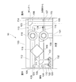
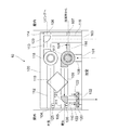
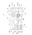
本発明の実施形態に係る浴室乾燥機について図1を参照しながら説明する。図1は、本発明の実施形態である浴室乾燥機10の概略構成を示す図である。図1に示すように浴室乾燥機10は、本体100に、浴室内から空気を取り入れるための換気口101と、換気口101から取り入れた空気の少なくとも一部を浴室内へと還流させるための循環吹出口102と、浴室内に空気を供給するための給気口103と、浴室外(本実施形態の場合は屋外)から空気を取り入れるための外気口104と、換気口101から取り入れた空気の少なくとも一部を浴室外(本実施形態の場合は屋外)へ排出するための排気口105と、リビングといった浴室外の他室へと空気を供給するための第二給気口106と、洗面所といった浴室外の他室から空気を取り入れるための第二換気口107とが設けられている。
A bathroom dryer according to an embodiment of the present invention will be described with reference to FIG. FIG. 1 is a diagram showing a schematic configuration of a
本体100内には、浴室内の空気を循環させたり排気させたりするために換気口101から空気を吸い込んで吹き出す循環排気ファン117と、浴室内に空気を供給するために外気口104から空気を吸い込んで吹き出す給気ファン118とが設けられている。本体100内にはまた、循環排気ファン117が吹き出す空気と給気ファン118が吸い込む空気との間で熱交換を行うための熱交換器119が設けられている。本体100内にはまた、循環排気ファン117が吹き出した空気を、排気口105と循環吹出口102とに分配比率を変えて供給する第一ダンパ121と、給気ファン118が吹き出した空気を、給気口103と第二給気口106とに分配比率を変えて供給する第二ダンパ123とが設けられている。第一ダンパ121及び第二ダンパ123は、ロータリーダンパによって構成されている。
In the
本体100内には、換気口101と循環排気ファン117とを繋ぐ流路108と、循環排気ファン117と第一ダンパ121とを繋ぐ流路109と、第一ダンパ121と排気口とを繋ぐ流路111と、第一ダンパ121と循環吹出口102とを繋ぐ流路110とが設けられている。流路109は、循環排気ファン117から熱交換器119を経由して第一ダンパ121に至るように設けられている。流路110には、第一ダンパ121側から、流路絞り122、ヒータ120が設けられている。流路絞り122は、所定の運転モードを実行する場合には流路110の一部を閉塞し、別の運転モードを実行する場合には流路110を開放するように制御されるものである。ヒータ120は、流路110を通る空気を加熱することが可能なように構成されている。
In the
本体100内には、外気口104と給気ファン118とを繋ぐ流路112と、給気ファン118と第二ダンパ123とを繋ぐ流路113と、第二ダンパ123と第二給気口106とを繋ぐ流路114と、第二ダンパ123と給気口103とを繋ぐ流路115とが設けられている。流路112は、外気口104から熱交換器119を経由して給気ファン118に至るように設けられている。
In the
本体100内には、第二換気口107と循環排気ファン117とを繋ぐ流路116が設けられている。流路116には開閉ダンパである第三ダンパ124が設けられている。第三ダンパ124によって流路116を塞ぐと、循環排気ファン117の駆動によって浴室側の換気口101からのみ空気を吸い込み、第三ダンパ124を開くと、換気口101からの吸い込みに併せて循環排気ファン117の駆動によって洗面所といった他室から第二換気口107を経由して空気を吸い込むことができる。
In the
本体100の外気口104近傍には、外気口104から吸い込まれる空気の温度を検出する外気温度センサ125(外気温度検出手段)が設けられている。本体100の排気口105近傍には、排気口105から吹き出される空気の温度を検出する排気温度センサ126(排気温度検出手段)が設けられている。
In the vicinity of the
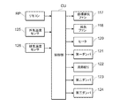
続いて、本実施形態の浴室乾燥機10の制御的な構成について図2を参照しながら説明する。図2は、浴室乾燥機10の制御的な構成を示すブロック図である。図2に示すように、制御部CU(制御手段)は、リモコンRP、外気温度センサ125、排気温度センサ126からの入力信号を受け付け、循環排気ファン117、給気ファン118、ヒータ120、第一ダンパ121、流路絞り122、第二ダンパ123、第三ダンパ124に対する指示信号を出力するように構成されている。制御部CUは、例えば、プロセッサ及びメモリにより構成されている。そして、リモコンRPの操作により浴室乾燥機10の運転が開始されると、予めメモリに記憶されたプログラムをプロセッサが実行し、外気温度センサ125,排気温度センサ126からの信号を入力し、循環排気ファン117,給気ファン118,ヒータ120,第一ダンパ121,流路絞り122,第二ダンパ123,第三ダンパ124に対する指示信号を出力することで、浴室乾燥機10の制御を行う。
Next, a control configuration of the
上述したような構成の浴室乾燥機10では、温風乾燥モード、熱回収温風乾燥モード、温風暖房モード、浴室熱回収モード、換気モード、熱回収換気モード、涼風モードといった多様な運転モードを実行することができる。引き続いて、各運転モードの詳細を説明する。
In the
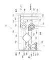
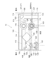
温風乾燥モードについて説明する。温風乾燥モードは、梅雨時期や冬季等で洗濯物が外に干せない場合に、浴室内に干した洗濯物にヒータ120で加熱した温風を当て、洗濯物からの水分の蒸発を促し、そして、洗濯物から蒸発した水分を含む高温多湿の空気を外部へ排出することにより洗濯物を乾燥させるための運転モードである。図3は、温風乾燥モードを実行する際の各部の動作を示す図である。図3において、制御部CUによって駆動制御される部分にはハッチングを施しており、その結果流れる空気は矢印で示している。以降の説明においても同様である。温風乾燥モードは、循環排気ファン117が吹き出した空気が、排気口105と循環吹出口102との双方に供給され、循環吹出口102に供給される空気がヒータ120によって加温されるものである。
The hot air drying mode will be described. The warm air drying mode applies warm air heated by the
まず、循環排気ファン117が回転駆動され、換気口101から吸込まれた空気が第一ダンパ121側へと吹き出される。第一ダンパ121は、循環排気ファン117から吹き出された空気の一部が循環吹出口102に向かい、残部が排気口105に向うような位置に制御される。流路絞り122は、排気側の流路圧損が高く排気口105の流量が低減し、循環吹出口102の流量が増加する場合に、流量のバランスを調整するために、流路110の一部を閉塞するような位置に制御される。ヒータ120には通電され、流路110を通って循環吹出口102に向う空気が加温される。
First, the
図3に示す温風乾燥モードでは、循環排気ファン117のみを回転駆動し、給気ファン118を停止しているので、省エネルギーに配慮した運転が可能となる。尚、循環排気ファン117の回転駆動によって、換気口101から吸込まれる空気と、循環吹出口102から浴室内に還流する空気との差分、すなわち排気口105から屋外へと排出される空気に相当する量の空気が浴室の扉のガラリ等から吸込まれる。
In the hot air drying mode shown in FIG. 3, only the
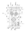
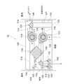
続いて、熱回収温風乾燥モードについて説明する。熱回収温風乾燥モードは、温風乾燥モードで洗濯物を乾燥する際に外気に排出される高温多湿の排気から熱を回収するための運転モードである。図4は、熱回収温風乾燥モードを実行する際の各部の動作を示す図である。熱回収温風乾燥モードは、循環排気ファン117から吹き出した空気が、排気口105と循環吹出口102との双方に供給され、循環吹出口102に供給される空気がヒータ120102によって加温されると共に、給気ファン118を駆動することで、循環排気ファン117が吹き出す空気から給気ファン118が吸い込む空気へと熱交換器119によって熱量を移動させるものである。
Next, the heat recovery hot air drying mode will be described. The heat recovery hot air drying mode is an operation mode for recovering heat from high-temperature and high-humidity exhaust discharged to the outside air when the laundry is dried in the hot air drying mode. FIG. 4 is a diagram illustrating the operation of each unit when the heat recovery hot air drying mode is executed. In the heat recovery hot air drying mode, the air blown from the
従って、循環排気ファン117が回転駆動され、換気口101から吸込まれた空気が第一ダンパ121側へと吹き出される。第一ダンパ121は、循環排気ファン117から吹き出された空気の一部が循環吹出口102に向かい、残部が排気口105に向うような位置に制御される。流路絞り122は、排気側の流路圧損が高く排気口105の流量が低減し、循環吹出口102の流量が増加する場合に、流量のバランスを調整するために、流路110の一部を閉塞するような位置に制御される。ヒータ120には通電され、流路110を通って循環吹出口102に向う空気が加温される。
Accordingly, the
また、給気ファン118も回転駆動され、外気口104から吸込まれた空気が第二ダンパ123側へと吹き出される。第二ダンパ123は、給気ファン118から吹き出された空気の全てが給気口103に向うような位置に制御される。このように、循環排気ファン117も給気ファン118も回転駆動されるので、循環排気ファン117が吹き出す空気から給気ファン118が吸い込む空気へと熱交換器119によって熱量を移動させることができる。図4に示す熱回収温風乾燥モードでは、循環排気ファン117が吹き出す空気が持つ熱量を給気ファン118が吸い込む空気へと移動させるので、排出する空気が持つ熱エネルギーを有効に活用することができる。
In addition, the
図3を参照しながら説明した温風乾燥モードと、図4を参照しながら説明した熱回収温風乾燥モードとは、任意に選択可能なモードとしても好ましいけれども、自動的に選択されるように構成することも好ましい。具体的には、制御部CUが、排気温度センサ126が検出した空気の温度が、外気温度センサ125が検出した空気の温度を上回ると熱回収温風乾燥モードを実行し、下回ると温風乾燥モードを実行するものである。
The hot air drying mode described with reference to FIG. 3 and the heat recovery hot air drying mode described with reference to FIG. 4 may be arbitrarily selected, but are automatically selected. It is also preferable to configure. Specifically, when the temperature of the air detected by the
排気温度が外気温度を下回っていることが検知されると、排気と給気との間で熱交換することは排気により給気温度が下げられることになり好ましくない。そこで、排気温度センサ126が検出した空気の温度が、外気温度センサ125が検出した空気の温度を上回ると、熱回収を行う熱回収温風乾燥モードを実行して効率的な熱回収運転を実行し、逆に下回ると熱回収を行わない温風乾燥モードを実行することで非効率な熱交換を行わないようにしている。その結果、熱回収を行う熱回収温風乾燥モードと熱回収を行わない温風乾燥モードとを、熱交換の効率を考慮して自動的に切り替えて運転することができる。
If it is detected that the exhaust gas temperature is lower than the outside air temperature, it is not preferable to exchange heat between the exhaust gas and the supply air because the supply air temperature is lowered by the exhaust. Therefore, when the temperature of the air detected by the
続いて、温風暖房モードについて説明する。温風暖房モードは、冬季等の寒い日に、入浴者の急激な温度変化によるヒートショックを和らげるために予め浴室全体を暖めておいたり、入浴中の浴室を暖めるための運転モードである。図5は、温風暖房モードを実行する際の各部の動作を示す図である。温風暖房モードは、循環排気ファン117が吹き出した空気が、循環吹出口102にのみ供給され、その供給される空気がヒータ120よって加温されるものである。
Next, the warm air heating mode will be described. The warm air heating mode is an operation mode for warming the entire bathroom in advance or for warming the bath during bathing in order to relieve a heat shock caused by a rapid temperature change of a bather on a cold day such as winter. FIG. 5 is a diagram illustrating the operation of each unit when executing the warm air heating mode. In the hot air heating mode, the air blown out from the
まず、循環排気ファン117が回転駆動され、換気口101から吸込まれた空気が第一ダンパ121側へと吹き出される。第一ダンパ121は、循環排気ファン117から吹き出された空気の全てが循環吹出口102に向うような位置に制御される。流路絞り122は、流路110を開放するような位置に制御される。ヒータ120には通電され、流路110を通って循環吹出口102に向う空気が加温される。
First, the
図5に示す温風暖房モードでは、循環排気ファン117のみを回転駆動し、給気ファン118を停止しているので、省エネルギーに配慮した運転が可能となる。
In the warm air heating mode shown in FIG. 5, only the
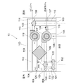
続いて、浴室熱回収モードについて説明する。浴室熱回収モードは、冬季等に居室の換気のために外気を導入する際に、浴室内の暖められた空気の熱を利用して導入される外気を暖めるための運転モードである。図6は、浴室熱回収モードを実行する際の各部の動作を示す図である。浴室熱回収モードは、循環排気ファン117が吹き出した空気が、循環吹出口102にのみ供給され、給気ファン118を駆動することで、循環排気ファン117が吹き出す空気から給気ファン118が吸い込む空気へと熱交換器119によって熱量を移動させ、給気ファン118が吹き出す空気はリビングといった他室へと供給されるものである。
Next, the bathroom heat recovery mode will be described. The bathroom heat recovery mode is an operation mode for warming the outside air introduced by using the heat of the warmed air in the bathroom when the outside air is introduced for ventilation of the living room in winter or the like. FIG. 6 is a diagram illustrating the operation of each unit when the bathroom heat recovery mode is executed. In the bathroom heat recovery mode, the air exhausted from the
従って、循環排気ファン117が回転駆動され、換気口101から吸込まれた空気が第一ダンパ121側へと吹き出される。第一ダンパ121は、循環排気ファン117から吹き出された空気の全てが循環吹出口102に向うような位置に制御される。流路絞り122は、流路110を解放するような位置に制御される。
Accordingly, the
また、給気ファン118も回転駆動され、外気口104から吸込まれた空気が第二ダンパ123側へと吹き出される。第二ダンパ123は、給気ファン118から吹き出された空気の全てが第二給気口106に向うような位置に制御される。このように、循環排気ファン117も給気ファン118も回転駆動されるので、循環排気ファン117が吹き出す空気から給気ファン118が吸い込む空気へと熱交換器119によって熱量を移動させることができる。すなわち、浴室内の熱を利用して他室へ暖気を供給することができる。
In addition, the
図6に示す浴室熱回収モードでは、循環排気ファン117が吹き出す空気が持つ熱量を給気ファン118が吸い込む空気へと移動させるので、排出する空気が持つ熱エネルギーを有効に活用することができる。
In the bathroom heat recovery mode shown in FIG. 6, the amount of heat of the air blown out by the
続いて、換気モードについて説明する。換気モードは、入浴後に浴室内に滞留した水蒸気を排出させたり、浴室の天井や壁面に付着した水滴を乾燥させるために浴室内の空気を入替えるための運転モードである。また、集合住宅では改正建築基準法で義務付けられた24時間換気流量を確保するための運転モードである。図7は、換気モードを実行する際の各部の動作を示す図である。換気モードは、循環排気ファン117が吹き出した空気が、排気口105に全て供給されるものである。
Subsequently, the ventilation mode will be described. The ventilation mode is an operation mode for exchanging air in the bathroom in order to discharge water vapor remaining in the bathroom after bathing or to dry water droplets adhering to the ceiling or wall surface of the bathroom. Moreover, in the apartment house, it is an operation mode for ensuring the 24-hour ventilation flow rate required by the revised Building Standard Law. FIG. 7 is a diagram illustrating the operation of each unit when the ventilation mode is executed. In the ventilation mode, all the air blown out from the
まず、循環排気ファン117が回転駆動され、換気口101から吸込まれた空気が第一ダンパ121側へと吹き出される。本実施形態の場合、洗面所といった他室の換気も同時に行うので、第三ダンパ124が開かれて、第二換気口107から吸込まれた空気も第一ダンパ121側へと吹き出される。第一ダンパ121は、循環排気ファン117から吹き出された空気の全てが排気口105に向うような位置に制御される。
First, the
図7に示す換気モードでは、循環排気ファン117のみを回転駆動し、給気ファン118を停止しているので、省エネルギーに配慮した運転が可能となる。尚、循環排気ファン117の回転駆動によって、換気口101から吸込まれる空気に相当する量の空気が浴室の扉のガラリ等から吸込まれる。
In the ventilation mode shown in FIG. 7, since only the
続いて、熱回収換気モードについて説明する。熱回収換気モードは、換気モードで浴室内の空気や居室内の空気を換気する際に、外部に排出される排気から熱を回収するための運転モードであって、特に夏季及び冬季に使用されることを想定した運転モードである。図8は、熱回収換気モードを実行する際の各部の動作を示す図である。熱回収換気モードは、循環排気ファン117が吹き出した空気が、排気口105にのみ供給されると共に、給気ファン118を駆動することで、循環排気ファン117が吹き出す空気から給気ファン118が吸い込む空気へと熱交換器119によって熱量を移動させるものであり、給気ファン118が吹き出す空気はリビングといった他室へと供給されるものである。
Next, the heat recovery ventilation mode will be described. The heat recovery ventilation mode is an operation mode for recovering heat from the exhaust exhausted to the outside when ventilating the air in the bathroom or the living room in the ventilation mode, and is used especially in summer and winter. This is an operation mode that assumes that FIG. 8 is a diagram illustrating the operation of each unit when executing the heat recovery ventilation mode. In the heat recovery ventilation mode, the air exhausted from the
まず、循環排気ファン117が回転駆動され、換気口101から吸込まれた空気が第一ダンパ121側へと吹き出される。本実施形態の場合、洗面所といった他室の換気も同時に行うので、第三ダンパ124が開かれて、第二換気口107から吸込まれた空気も第一ダンパ121側へと吹き出される。第一ダンパ121は、循環排気ファン117から吹き出された空気の全てが排気口105に向うような位置に制御される。
First, the
また、給気ファン118も回転駆動され、外気口104から吸込まれた空気が第二ダンパ123側へと吹き出される。第二ダンパ123は、給気ファン118から吹き出された空気の全てが第二給気口106に向うような位置に制御される。このように、循環排気ファン117も給気ファン118も回転駆動されるので、循環排気ファン117が吹き出す空気から給気ファン118が吸い込む空気へと熱交換器119によって熱量を移動させることができる。すなわち、浴室内の熱を利用して他室へ暖気を供給することができる。
In addition, the
図8に示す熱回収換気モードでは、循環排気ファン117が吹き出す空気が持つ熱量を給気ファン118が吸い込む空気へと移動させるので、排出する空気が持つ熱エネルギーを有効に活用することができる。
In the heat recovery ventilation mode shown in FIG. 8, the amount of heat of the air blown out by the
続いて、涼風モードについて説明する。涼風モードは、夏季等の入浴中に蒸し暑いと感じた場合に、浴室内に送風すると同時に換気することで蒸し暑さを軽減するための運転モードである。図9は、涼風モードを実行する際の各部の動作を示す図である。涼風モードは、循環排気ファン117が吹き出した空気が、排気口105と循環吹出口102との双方に供給されるものである。
Next, the cool breeze mode will be described. The cool breeze mode is an operation mode for reducing the sultry heat by ventilating and ventilating the bathroom when bathing in the summer or the like. FIG. 9 is a diagram illustrating the operation of each unit when the cool breeze mode is executed. In the cool breeze mode, the air blown out from the
まず、循環排気ファン117が回転駆動され、換気口101から吸込まれた空気が第一ダンパ121側へと吹き出される。第一ダンパ121は、循環排気ファン117から吹き出された空気の一部が循環吹出口102に向かい、残部が排気口105に向うような位置に制御される。流路絞り122は、排気側の流路圧損が高く排気口105の流量が低減し、循環吹出口102の流量が増加する場合に、流量のバランスを調整するために流路110の一部を閉塞するような位置に制御される。
First, the
図9に示す涼風モードでは、循環排気ファン117のみを回転駆動し、給気ファン118を停止しているので、省エネルギーに配慮した運転が可能となる。尚、循環排気ファン117の回転駆動によって、換気口101から吸込まれる空気と、循環吹出口102から浴室内に還流する空気との差分、すなわち排気口105から屋外へと排出される空気に相当する量の空気が浴室の扉のガラリ等から吸込まれる。
In the cool breeze mode shown in FIG. 9, only the
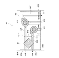
上述した本実施形態では、循環排気ファン117と第一ダンパ121との間の流路109に熱交換器119を設けているけれども、第一ダンパ121よりも下流側に熱交換器119を設けることも好ましい。このように、第一ダンパ121よりも下流側に熱交換器119を設ける例を図10に示す。このように、第一ダンパ121と排気口105とを繋ぐ流路111に熱交換器119を設けることで、浴室から排出される空気のみから熱を回収することができるため、熱交換器119を第一ダンパ121よりも上流側に設けるよりも熱回収効率を上げることができる。また、熱回収を行わない温風暖房モードにおいては、熱交換器119を通さずにヒータ120に空気を送り込むことができるので、熱交換器119の圧損による流体エネルギーの損失を低減するとともに、熱交換器119の劣化を抑制することができる。
In the present embodiment described above, the
10:浴室乾燥機
100:本体
101:換気口
102:循環吹出口
103:給気口
104:外気口
105:排気口
106:第二給気口
107:第二換気口
108,109,110,111,112,113,114,115,116:流路
117:循環排気ファン
118:給気ファン
119:熱交換器
120:ヒータ
121:第一ダンパ
122:流路絞り
123:第二ダンパ
124:第三ダンパ
125:外気温度センサ
126:排気温度センサ
CU:制御部
RP:リモコン
10: Bathroom dryer 100: Main body 101: Ventilation port 102: Circulation outlet 103: Air supply port 104: Outside air port 105: Exhaust port 106: Second air supply port 107:
Claims (5)
浴室外から空気を取り入れるための外気口と、
浴室内へ空気を供給するための給気口と、
浴室内から空気を取り入れるための換気口と、
前記換気口から取り入れた空気の少なくとも一部を浴室内へと還流させるための循環吹出口と、
前記換気口から取り入れた空気の少なくとも一部を浴室外へと排出するための排気口と、
前記換気口から空気を吸い込んで吹き出す循環排気ファンと、
前記外気口から空気を吸い込んで吹き出す給気ファンと、
前記循環排気ファンが吹き出した空気を、前記排気口と前記循環吹出口とに分配比率を変えて供給する第一ダンパと、
前記第一ダンパと前記循環吹出口との間に設けられたヒータと、
前記循環排気ファンが吹き出す空気と前記給気ファンが吸い込む空気との間で熱交換を行うための熱交換器と、
前記循環排気ファン、前記給気ファン、前記第一ダンパ、前記ヒータを制御するための制御手段と、を備え、
前記制御手段は、
前記循環排気ファンが吹き出した空気が、前記排気口と前記循環吹出口との双方に供給され、前記循環吹出口に供給される空気が前記ヒータによって加温される温風乾燥モードと、
前記循環排気ファンが吹き出した空気が、前記排気口と前記循環吹出口との双方に供給され、前記循環吹出口に供給される空気が前記ヒータによって加温されると共に、前記給気ファンを駆動することで、前記循環排気ファンが吹き出す空気から前記給気ファンが吸い込む空気へと前記熱交換器によって熱量を移動させる熱回収温風乾燥モードと、を実行可能なように構成されていることを特徴とする浴室乾燥機。 A bathroom dryer capable of sucking air in the bathroom and drying the bathroom,
An outdoor vent for taking air from outside the bathroom,
An air inlet for supplying air into the bathroom;
A vent for taking air from inside the bathroom;
A circulation outlet for recirculating at least part of the air taken in from the ventilation port into the bathroom;
An exhaust port for discharging at least part of the air taken from the ventilation port to the outside of the bathroom;
A circulation exhaust fan that sucks air from the ventilation port and blows it out;
An air supply fan for sucking air from the outside air outlet and blowing it out;
A first damper that supplies the air blown out by the circulation exhaust fan to the exhaust outlet and the circulation outlet at a different distribution ratio;
A heater provided between the first damper and the circulation outlet;
A heat exchanger for performing heat exchange between the air blown out by the circulation exhaust fan and the air sucked in by the air supply fan;
A control means for controlling the circulation exhaust fan, the air supply fan, the first damper, and the heater;
The control means includes
The hot air drying mode in which the air blown out by the circulation exhaust fan is supplied to both the exhaust outlet and the circulation outlet, and the air supplied to the circulation outlet is heated by the heater;
The air blown out by the circulation exhaust fan is supplied to both the exhaust outlet and the circulation outlet, and the air supplied to the circulation outlet is heated by the heater and drives the air supply fan. The heat recovery warm air drying mode in which the amount of heat is transferred by the heat exchanger from the air blown by the circulation exhaust fan to the air sucked by the air supply fan is configured to be executable. Features a bathroom dryer.
前記制御手段は、前記循環排気ファンが吹き出した空気が、前記循環吹出口にのみ供給され、その供給される空気が前記ヒータによって加温される温風暖房モードを更に実行可能なように構成され、
前記制御手段は、前記温風乾燥モード及び前記熱回収温風乾燥モードの実行時には前記流路の一部を閉塞し、前記温風暖房モードの実行時には前記流路を開放するように前記流路絞りを制御することを特徴とする請求項2に記載の浴室乾燥機。 In the flow path from the first damper to the circulation outlet, a flow path restriction capable of closing and opening a part of the flow path is provided,
The control means is configured to further execute a hot air heating mode in which the air blown out by the circulation exhaust fan is supplied only to the circulation outlet, and the supplied air is heated by the heater. ,
The control means closes a part of the flow path when the hot air drying mode and the heat recovery hot air drying mode are executed, and opens the flow path when the hot air heating mode is executed. The bathroom dryer according to claim 2, wherein the diaphragm is controlled.
前記制御手段は、前記排気温度検出手段が検出した空気の温度が、前記外気温度検出手段が検出した空気の温度を上回ると前記熱回収温風乾燥モードを実行し、下回ると前記温風乾燥モードを実行することを特徴とする請求項1に記載の浴室乾燥機。 Exhaust temperature detection means for detecting the temperature of air blown from the exhaust port, and outside air temperature detection means for detecting the temperature of air sucked from the outside air port,
The control means executes the heat recovery hot air drying mode when the temperature of the air detected by the exhaust temperature detecting means exceeds the temperature of the air detected by the outside air temperature detecting means, and when the temperature is lower, the hot air drying mode The bathroom dryer according to claim 1, wherein:
前記給気ファンよりも前記給気口に向かって下流側に、前記給気ファンが吹き出した空気を、前記給気口と前記第二給気口とに分配比率を変えて供給する第二ダンパと、を備え、
前記制御手段は、前記給気ファンが吹き出した空気が、前記第二給気口にのみ供給されるように前記第二ダンパを制御し、前記循環排気ファンが吹き出した空気が、前記循環吹出口にのみ供給される供給されるように前記第一ダンパを制御することで、前記熱交換器によって前記循環排気ファンが吹き出す空気から前記給気ファンが吸い込む空気へと熱量を移動させる浴室熱回収モードを実行可能なように構成されていることを特徴とする請求項1に記載の浴室乾燥機。 A second air supply port for supplying air to other rooms other than the bathroom;
A second damper that supplies the air blown out by the air supply fan to the air supply port and the second air supply port with a distribution ratio changed downstream from the air supply fan toward the air supply port. And comprising
The control means controls the second damper so that the air blown out from the air supply fan is supplied only to the second air supply port, and the air blown out from the circulation exhaust fan is supplied to the circulation blowout port. By controlling the first damper so as to be supplied only to the air, the heat exchanger moves the amount of heat from the air blown by the circulation exhaust fan to the air sucked by the air supply fan by the heat exchanger. The bathroom dryer according to claim 1, wherein the bathroom dryer is configured to be capable of performing the following.
Priority Applications (1)
| Application Number | Priority Date | Filing Date | Title |
|---|---|---|---|
| JP2009222791A JP5370923B2 (en) | 2009-09-28 | 2009-09-28 | Bathroom Dryer |
Applications Claiming Priority (1)
| Application Number | Priority Date | Filing Date | Title |
|---|---|---|---|
| JP2009222791A JP5370923B2 (en) | 2009-09-28 | 2009-09-28 | Bathroom Dryer |
Publications (2)
| Publication Number | Publication Date |
|---|---|
| JP2011069578A true JP2011069578A (en) | 2011-04-07 |
| JP5370923B2 JP5370923B2 (en) | 2013-12-18 |
Family
ID=44015007
Family Applications (1)
| Application Number | Title | Priority Date | Filing Date |
|---|---|---|---|
| JP2009222791A Active JP5370923B2 (en) | 2009-09-28 | 2009-09-28 | Bathroom Dryer |
Country Status (1)
| Country | Link |
|---|---|
| JP (1) | JP5370923B2 (en) |
Cited By (2)
| Publication number | Priority date | Publication date | Assignee | Title |
|---|---|---|---|---|
| CN103727659A (en) * | 2014-01-16 | 2014-04-16 | 湖南大学 | Thermoelectricity heat recovery fan heater for bathroom |
| JP2017181016A (en) * | 2016-03-28 | 2017-10-05 | パナソニックIpマネジメント株式会社 | Bathroom heating dryer |
Citations (3)
| Publication number | Priority date | Publication date | Assignee | Title |
|---|---|---|---|---|
| JPH06137759A (en) * | 1992-10-27 | 1994-05-20 | Matsushita Seiko Co Ltd | Clothing dryer for bath room |
| JP2002306900A (en) * | 2001-04-17 | 2002-10-22 | Matsushita Electric Works Ltd | Indoor clothes drying device |
| JP2006071222A (en) * | 2004-09-03 | 2006-03-16 | Matsushita Electric Ind Co Ltd | Simultaneous air supply/discharge type bathroom ventilating heating drying machine |
-
2009
- 2009-09-28 JP JP2009222791A patent/JP5370923B2/en active Active
Patent Citations (3)
| Publication number | Priority date | Publication date | Assignee | Title |
|---|---|---|---|---|
| JPH06137759A (en) * | 1992-10-27 | 1994-05-20 | Matsushita Seiko Co Ltd | Clothing dryer for bath room |
| JP2002306900A (en) * | 2001-04-17 | 2002-10-22 | Matsushita Electric Works Ltd | Indoor clothes drying device |
| JP2006071222A (en) * | 2004-09-03 | 2006-03-16 | Matsushita Electric Ind Co Ltd | Simultaneous air supply/discharge type bathroom ventilating heating drying machine |
Cited By (2)
| Publication number | Priority date | Publication date | Assignee | Title |
|---|---|---|---|---|
| CN103727659A (en) * | 2014-01-16 | 2014-04-16 | 湖南大学 | Thermoelectricity heat recovery fan heater for bathroom |
| JP2017181016A (en) * | 2016-03-28 | 2017-10-05 | パナソニックIpマネジメント株式会社 | Bathroom heating dryer |
Also Published As
| Publication number | Publication date |
|---|---|
| JP5370923B2 (en) | 2013-12-18 |
Similar Documents
| Publication | Publication Date | Title |
|---|---|---|
| US10928093B2 (en) | Heat exchange ventilator | |
| JP2001116290A (en) | Heating dryer | |
| JP4735573B2 (en) | Ventilation air conditioner | |
| JP5237782B2 (en) | Heat exchange ventilator | |
| KR200461855Y1 (en) | Ventilation System | |
| JP2011220639A (en) | Heat exchange ventilator | |
| TW201239164A (en) | Bathroom dryer | |
| JP5370923B2 (en) | Bathroom Dryer | |
| JP6675057B2 (en) | Heat exchange ventilator | |
| JP4042688B2 (en) | Bathroom air conditioner | |
| JP4478004B2 (en) | Air conditioner | |
| JP2005164113A (en) | Ventilation device | |
| JP5096788B2 (en) | Ventilation system | |
| JP3959181B2 (en) | Heat exchange ventilation system | |
| JP2010091208A (en) | Ventilation air conditioner | |
| KR101243227B1 (en) | Ventilation System and control Method of the same of | |
| JP2005351505A (en) | Air conditioner | |
| JP2019135421A (en) | Bathroom heating device | |
| JP2005164114A (en) | Bathroom air conditioning system | |
| JP2011069579A (en) | Bathroom dryer | |
| JP3839707B2 (en) | Operation method of bathroom heating dryer and total heat exchanger | |
| JP2006112684A (en) | Air conditioning ventilation system | |
| JP2011069580A (en) | Bathroom dryer | |
| JP2000074446A (en) | Heat exchanging ventilation system | |
| JP5921221B2 (en) | Indirect evaporative cooling type cooling system |
Legal Events
| Date | Code | Title | Description |
|---|---|---|---|
| A621 | Written request for application examination |
Free format text: JAPANESE INTERMEDIATE CODE: A621 Effective date: 20120726 |
|
| A977 | Report on retrieval |
Free format text: JAPANESE INTERMEDIATE CODE: A971007 Effective date: 20130821 |
|
| TRDD | Decision of grant or rejection written | ||
| A01 | Written decision to grant a patent or to grant a registration (utility model) |
Free format text: JAPANESE INTERMEDIATE CODE: A01 Effective date: 20130826 |
|
| R150 | Certificate of patent or registration of utility model |
Ref document number: 5370923 Country of ref document: JP Free format text: JAPANESE INTERMEDIATE CODE: R150 Free format text: JAPANESE INTERMEDIATE CODE: R150 |
|
| A61 | First payment of annual fees (during grant procedure) |
Free format text: JAPANESE INTERMEDIATE CODE: A61 Effective date: 20130908 |