JP2011069481A - Valve device and method of driving the same - Google Patents
Valve device and method of driving the same Download PDFInfo
- Publication number
- JP2011069481A JP2011069481A JP2009223414A JP2009223414A JP2011069481A JP 2011069481 A JP2011069481 A JP 2011069481A JP 2009223414 A JP2009223414 A JP 2009223414A JP 2009223414 A JP2009223414 A JP 2009223414A JP 2011069481 A JP2011069481 A JP 2011069481A
- Authority
- JP
- Japan
- Prior art keywords
- time
- current
- energization
- predetermined
- plunger
- Prior art date
- Legal status (The legal status is an assumption and is not a legal conclusion. Google has not performed a legal analysis and makes no representation as to the accuracy of the status listed.)
- Granted
Links
- 238000000034 method Methods 0.000 title claims description 53
- 238000012544 monitoring process Methods 0.000 claims abstract description 8
- 230000010354 integration Effects 0.000 claims description 2
- 238000001514 detection method Methods 0.000 description 27
- XLYOFNOQVPJJNP-UHFFFAOYSA-N water Substances O XLYOFNOQVPJJNP-UHFFFAOYSA-N 0.000 description 21
- 238000005259 measurement Methods 0.000 description 18
- 238000010586 diagram Methods 0.000 description 9
- 230000005611 electricity Effects 0.000 description 9
- 239000003990 capacitor Substances 0.000 description 8
- 238000006243 chemical reaction Methods 0.000 description 8
- 230000000694 effects Effects 0.000 description 6
- 238000010248 power generation Methods 0.000 description 5
- 230000007613 environmental effect Effects 0.000 description 4
- 238000004140 cleaning Methods 0.000 description 3
- 230000007423 decrease Effects 0.000 description 3
- 238000013459 approach Methods 0.000 description 2
- 239000012530 fluid Substances 0.000 description 2
- 230000006870 function Effects 0.000 description 2
- 238000012545 processing Methods 0.000 description 2
- 238000005406 washing Methods 0.000 description 2
- 101710170230 Antimicrobial peptide 1 Proteins 0.000 description 1
- 230000004397 blinking Effects 0.000 description 1
- 238000012423 maintenance Methods 0.000 description 1
- 230000007257 malfunction Effects 0.000 description 1
- 238000003825 pressing Methods 0.000 description 1
Images


Landscapes
- Magnetically Actuated Valves (AREA)
- Electromagnets (AREA)
Abstract
Description
本発明は、ソレノイドを用いたラッチング式のバルブ装置およびその駆動方法に関する。 The present invention relates to a latching type valve device using a solenoid and a driving method thereof.
ラッチング式のソレノイドバルブは、従来から水やガスなどの流体の経路を開閉するために用いられており、コイルへの通電によりプランジャを移動させて、永久磁石あるいはバネによってプランジャをその移動後の位置に保持する。 A latching type solenoid valve has been conventionally used to open and close a fluid path such as water or gas. The plunger is moved by energizing a coil, and the plunger is moved to a position after the movement by a permanent magnet or a spring. Hold on.
開状態と閉状態との切替え時には、ソレノイドバルブは電力を用いてプランジャを移動させる。一方、流路の開状態または閉状態の維持時には、ソレノイドバルブは、電力を用いず、永久磁石の磁力またはバネの弾性力を利用してプランジャを保持する。このように、ソレノイドバルブは開閉状態の切替え時にのみコイルへ通電すれば足りるので、省電力化に優れている。 When switching between the open state and the closed state, the solenoid valve moves the plunger using electric power. On the other hand, when maintaining the open state or the closed state of the flow path, the solenoid valve holds the plunger using the magnetic force of the permanent magnet or the elastic force of the spring without using electric power. In this way, the solenoid valve is excellent in power saving because it is sufficient to energize the coil only at the time of switching the open / close state.
しかし、近年、例えばソレノイドバルブを使用した自動水栓では製品の小型化が急速に進み、電力供給源である発電機や電池も小型化が要求されている。小型化すれば必然的に供給電力も少なくなる。このような自動水栓では使用可能な電力量が限られるため、ソレノイドバルブの消費電力の削減がさらに望まれている。 However, in recent years, for example, automatic faucets using solenoid valves have been rapidly miniaturized, and generators and batteries that are power supply sources have been required to be miniaturized. Miniaturization will inevitably reduce power supply. In such an automatic faucet, the amount of power that can be used is limited, and therefore, reduction of the power consumption of the solenoid valve is further desired.
これに対処するために、特許文献1に記載の装置は、ボトム検知とコイルへの通電時間との組合せによってソレノイドバルブの開閉を制御している。ボトム検知とは、コイルへの通電開始後、コイルに流れる電流の変曲点(ボトム)を検知することである。特許文献1では、コイルに流れる電流の変曲点が発生した時点を、プランジャの移動が完了した時点とみなして、ボトム検知時にコイルへの通電を停止する。しかし、コイルに流れる電流の変曲点は、ノイズによる誤動作等によってプランジャの移動完了よりも明らかに早く発生する場合がある。この場合、特許文献1に記載の装置は、変曲点を検知したとしても、コイルへの通電を停止することなく、通電開始から或る所定時間が経過するまでコイルへの通電を継続する。つまり、特許文献1では、ボトム検知が早すぎた場合に、コイルへの通電を時間で制御する。 In order to cope with this, the device described in Patent Document 1 controls opening and closing of the solenoid valve by a combination of bottom detection and energization time to the coil. The bottom detection is to detect an inflection point (bottom) of a current flowing through the coil after energization of the coil is started. In Patent Document 1, the time when the inflection point of the current flowing through the coil is generated is regarded as the time when the movement of the plunger is completed, and energization of the coil is stopped when the bottom is detected. However, the inflection point of the current flowing through the coil may occur clearly earlier than the completion of the movement of the plunger due to malfunction due to noise or the like. In this case, even if the apparatus described in Patent Document 1 detects an inflection point, it does not stop energizing the coil and continues energizing the coil until a predetermined time elapses from the start of energization. That is, in patent document 1, when bottom detection is too early, electricity supply to a coil is controlled by time.
しかしながら、コイルへの通電は、プランジャの移動が確実に完了した時点まで継続させる必要がある。そのため、通電時間を充分に長く設定する必要があり、その結果として無駄な電力を消費していた。例えば、自動水栓では、開状態から閉状態に切り替わるとき、プランジャはダイヤフラム弁を押しながら移動を完了する。このため、プランジャが開状態から閉状態に切り替わる際に、コイルに流れる電流の変曲点が明確に現れず、ボトム検知ができない場合が多い。このような場合、特許文献1に記載の技術では、コイルへの通電を時間によって制御する機会が多くなるため、消費電力を充分に削減できないという問題が生じる。 However, energization of the coil needs to be continued until the plunger movement is reliably completed. Therefore, it is necessary to set the energization time sufficiently long, and as a result, wasteful power is consumed. For example, in an automatic faucet, when switching from an open state to a closed state, the plunger completes the movement while pushing the diaphragm valve. For this reason, when the plunger is switched from the open state to the closed state, the inflection point of the current flowing through the coil does not appear clearly, and often bottom detection cannot be performed. In such a case, the technique described in Patent Document 1 has a problem that the power consumption cannot be sufficiently reduced because there are many opportunities to control the energization of the coil with time.
本発明は、上記課題を解決するためになされたものであり、本発明の目的は、プランジャの移動を正確に検知し、ラッチング式のソレノイドバルブを駆動する際の消費電力を削減することである。 The present invention has been made to solve the above-described problems, and an object of the present invention is to accurately detect the movement of the plunger and reduce the power consumption when driving the latching solenoid valve. .
請求項1に係る発明は、ソレノイドコイルへの通電により移動するプランジャと、該プランジャの移動によって流路を開閉するように駆動される弁体と、前記ソレノイドコイルへの通電を制御する制御部とを備えたラッチング式のバルブ装置であって、前記制御部は、通電時に前記ソレノイドコイルを流れる電流または該電流に応じた電圧を監視する監視部と、前記電流または前記電圧が所定電流値または所定電圧値に達した時点から計時するタイマ部と、前記所定電流値または前記所定電圧値を記憶する記憶部とを備え、前記電流または前記電圧が前記所定電流値または前記所定電圧値に達した時点から所定時間の経過後に、前記ソレノイドコイルへの通電を停止することを特徴とする。これにより、プランジャの移動完了後の無駄な通電時間を可及的に短くし、ソレノイドにおける無駄な消費電力を削減することができる。 According to a first aspect of the present invention, there is provided a plunger that is moved by energizing the solenoid coil, a valve body that is driven so as to open and close the flow path by the movement of the plunger, and a control unit that controls energization of the solenoid coil; The control unit includes: a monitoring unit that monitors a current flowing through the solenoid coil or a voltage corresponding to the current when energized; and the current or the voltage is a predetermined current value or a predetermined value. A timer unit that counts from the time when the voltage value is reached, and a storage unit that stores the predetermined current value or the predetermined voltage value, and the time point when the current or the voltage reaches the predetermined current value or the predetermined voltage value After a predetermined time elapses, the energization to the solenoid coil is stopped. Thereby, the useless energization time after completion of the movement of the plunger can be shortened as much as possible, and useless power consumption in the solenoid can be reduced.
請求項2に係る発明は、前記電流または前記電圧が所定電流値または所定電圧値に達した時点以降、前記電流または前記電圧を前記所定電流値または所定電圧値に維持することを特徴とする。これにより、電流を所定電流値以下に制限するので、無駄な消費電流をさらに削減しつつ、プランジャを確実に移動完了させることがきる。 The invention according to claim 2 is characterized in that the current or the voltage is maintained at the predetermined current value or the predetermined voltage value after the current or the voltage reaches the predetermined current value or the predetermined voltage value. As a result, the current is limited to a predetermined current value or less, so that it is possible to reliably complete the movement of the plunger while further reducing unnecessary current consumption.
請求項3に係る発明は、前記電流または前記電圧が所定電流値または所定電圧値に達した時点以降、前記ソレノイドコイルへの通電の停止と開始とを繰り返すことによって前記電流または前記電圧を前記所定電流値または所定電圧値に維持することを特徴とする。これにより、電流を所定電流値以下に制限するので、無駄な消費電流をさらに削減しつつ、プランジャを確実に移動完了させることがきる。また、追加の構成要素が不要となるので、制御部の回路規模の増大を抑制できる。 According to a third aspect of the present invention, after the current or voltage reaches a predetermined current value or a predetermined voltage value, the current or the voltage is applied to the predetermined current by repeatedly stopping and starting energization of the solenoid coil. A current value or a predetermined voltage value is maintained. As a result, the current is limited to a predetermined current value or less, so that it is possible to reliably complete the movement of the plunger while further reducing unnecessary current consumption. Moreover, since an additional component is unnecessary, an increase in the circuit scale of the control unit can be suppressed.
請求項4に係る発明は、前記電流または前記電圧が所定電流値または所定電圧値に達した時点以降、前記ソレノイドコイルへ供給した前記電流を積算した積算電気量を算出する積算部をさらに備え、前記所定時間の経過より前に前記積算電気量が所定の閾値電気量に達した場合、該積算電気量が前記閾値電気量に達した時点で前記ソレノイドコイルへの通電を停止することを特徴とする。これにより、プランジャの移動開始後、所定時間の経過を待つことなく、積算電気量に基づいてソレノイドコイルへの通電を停止するので、無駄な消費電流をさらに削減しつつ、プランジャを確実に移動完了させることがきる。 The invention according to claim 4 further includes an integrating unit that calculates an integrated electric quantity obtained by integrating the current supplied to the solenoid coil after the time when the current or the voltage reaches a predetermined current value or a predetermined voltage value. When the integrated electric quantity reaches a predetermined threshold electric quantity before the lapse of the predetermined time, the energization to the solenoid coil is stopped when the integrated electric quantity reaches the threshold electric quantity. To do. As a result, the energization of the solenoid coil is stopped based on the accumulated amount of electricity without waiting for the elapse of a predetermined time after the start of the movement of the plunger, so that the movement of the plunger is reliably completed while further reducing unnecessary current consumption. I can make it.
請求項5に係る発明は、前記ソレノイドコイルへの通電を開始した時点から前記電流または前記電圧が前記所定電流値または前記所定電圧値に達した時点までの初期時間を計時し、前記初期時間に基づいて前記所定時間を変更することを特徴とする。これにより、プランジャの移動速度に応じて前記所定時間を設定することができるので、無駄な消費電力を削減しつつ、プランジャの移動を完了させることがきる。 According to a fifth aspect of the present invention, an initial time from when the energization to the solenoid coil is started to when the current or the voltage reaches the predetermined current value or the predetermined voltage value is measured, and the initial time is set to the initial time. Based on the above, the predetermined time is changed. Thereby, since the said predetermined time can be set according to the moving speed of a plunger, the movement of a plunger can be completed, reducing useless power consumption.
請求項6に係る発明は、前記ソレノイドコイルへの通電を開始した時点から前記電流または前記電圧が前記所定電流値または前記所定電圧値に達した時点までの初期時間を計時し、前記初期時間が予め設定された第1の閾値時間よりも小さい場合、前記制御部が、当該バルブ装置内において故障が生じていることをユーザに通知し、前記ソレノイドコイルへの通電を停止することを特徴とする。これにより、バルブ装置内におけるショート故障を検出することができる。 According to a sixth aspect of the present invention, the initial time from when the energization to the solenoid coil is started to when the current or the voltage reaches the predetermined current value or the predetermined voltage value is measured, and the initial time is measured. When the time is shorter than a preset first threshold time, the control unit notifies the user that a failure has occurred in the valve device, and stops energization of the solenoid coil. . Thereby, a short circuit failure in the valve device can be detected.
請求項7に係る発明は、前記ソレノイドコイルへの通電を開始した時点から計時を開始し、前記ソレノイドコイルへの通電を開始した時点から予め設定された第2の閾値時間の経過までに、前記電流または前記電圧が前記所定電流値または前記所定電圧値に達しない場合、前記制御部が、当該バルブ装置内において故障が生じていることをユーザに通知し、前記ソレノイドコイルへの通電を停止すると判断することを特徴とする。これにより、バルブ装置内におけるオープン故障を検出することができる。 The invention according to claim 7 starts timing from the time when energization to the solenoid coil is started, and from the time when energization to the solenoid coil is started until a preset second threshold time elapses. When the current or the voltage does not reach the predetermined current value or the predetermined voltage value, the control unit notifies the user that a failure has occurred in the valve device and stops energizing the solenoid coil. It is characterized by judging. Thereby, an open failure in the valve device can be detected.
請求項8に係る発明は、前記所定電流値が前記プランジャの移動開始時に前記ソレノイドコイルに供給されている電流値であり、前記所定電圧値が前記プランジャの移動開始時に前記ソレノイドコイルに供給されている電流値に対応する電圧値であることを特徴とする。これにより、プランジャの移動完了後の無駄な通電時間を可及的に短くし、ソレノイドにおける無駄な消費電力を削減することができる。 In the invention according to claim 8, the predetermined current value is a current value supplied to the solenoid coil at the start of movement of the plunger, and the predetermined voltage value is supplied to the solenoid coil at the start of movement of the plunger. It is a voltage value corresponding to a current value. Thereby, the useless energization time after completion of the movement of the plunger can be shortened as much as possible, and useless power consumption in the solenoid can be reduced.
請求項9に係る発明は、ソレノイドコイルへの通電により移動するプランジャと、該プランジャの移動によって流路を開閉するように駆動される弁体と、前記ソレノイドコイルへの通電を制御する制御部とを備えたラッチング式のバルブ装置の駆動方法であって、前記制御部は通電時に前記ソレノイドコイルへ供給される電流または該電流に応じた電圧を監視し、前記制御部は前記電流または前記電圧が所定電流値または所定電圧値に達した時点から計時し、前記電流または前記電圧が所定電流値または所定電圧値に達した時点から所定時間の経過後に、前記制御部は前記ソレノイドコイルへの通電を停止することを具備したことを特徴とする。これにより、プランジャの移動完了後の無駄な通電時間を可及的に短くし、ソレノイドにおける無駄な消費電力を削減することができる。 The invention according to claim 9 is a plunger that moves by energizing the solenoid coil, a valve body that is driven to open and close the flow path by the movement of the plunger, and a controller that controls energization to the solenoid coil; The control unit monitors a current supplied to the solenoid coil or a voltage corresponding to the current when energized, and the control unit detects whether the current or the voltage is The time is measured from the time when the predetermined current value or the predetermined voltage value is reached, and after a predetermined time has elapsed from the time when the current or the voltage reaches the predetermined current value or the predetermined voltage value, the control unit energizes the solenoid coil. It is characterized by comprising stopping. Thereby, the useless energization time after completion of the movement of the plunger can be shortened as much as possible, and useless power consumption in the solenoid can be reduced.
以下、図面を参照して本発明に係る実施形態を説明する。本実施形態は、本発明を限定するものではない。 Embodiments according to the present invention will be described below with reference to the drawings. This embodiment does not limit the present invention.
(第1の実施形態)
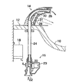
図1は、本発明に係る第1の実施形態に従った自動水栓を用いた手洗器の一例を示す断面図である。本実施形態による手洗器は、ボール10の天板12に装着された水栓金具14と、天板12の下方に位置するバルブ装置としてのバルブユニット16と、壁面に固定された電池18とを備えている。
(First embodiment)
FIG. 1 is a sectional view showing an example of a hand-washing basin using an automatic water faucet according to the first embodiment of the present invention. The hand wash basin according to the present embodiment includes a faucet fitting 14 mounted on the
水栓金具14は、人体検知およびバルブユニット16の開閉等の制御を行う制御部としてのコントロールユニット30を備えている。コントロールユニット30は、回路基板31を介して水栓金具14に固定されている。回路基板31は、マイクロコンピュータ、LED(Light Emitting Diode)、フォトダイオード等の電子デバイスを実装している。LEDは、ボール10に向かって開口された窓28を介して周期的に赤外線を発し、フォトダイオードは、ボール10から反射した赤外線を検知する。
The faucet fitting 14 includes a
フォトダイオードが人体を検知したときには、バルブユニット16の弁体としてのダイヤフラムバルブ20は一次側流路22と二次側流路24との間を開き、吐水金具26から吐水する。フォトダイオードが人体を検知していないときには、ダイヤフラムバルブ20は一次側流路22と二次側流路24との間を閉じ、吐水金具26からの吐水を停止する。
When the photodiode detects a human body, the
図2は、ラッチング式のソレノイドバルブ23(以下、単にバルブ23ともいう)の構成の一例を示す断面図である。バルブ23は、ダイヤフラム弁20と、プランジャ40と、永久磁石50(以下、単に磁石50という)と、バネ52と、ソレノイドコイル54と、クリーニングピン45と、圧力室48とを備えている。
FIG. 2 is a cross-sectional view showing an example of the configuration of a latching solenoid valve 23 (hereinafter also simply referred to as a valve 23). The
ダイヤフラム弁20は、一次側流路22と二次側流路24との間を開閉するように構成されている。プランジャ40は、ダイヤフラム弁20に設けられたパイロット穴47を開閉するように構成されている。
永久磁石50(以下、単に磁石50という)は、ダイヤフラム弁20を開状態にするためにプランジャ40を引き付ける。バネ52は、ダイヤフラム弁20を閉状態にするためにプランジャ40をダイヤフラム弁20へ向かって押し付ける。磁石50がプランジャ40を引き付ける力と、バネ52がプランジャ40を押す力とは、互いに斥力である。プランジャ40が磁石50に接近すると、磁石50による力がバネ52による力を勝り、ダイヤフラム弁20を開状態にする。一方、プランジャ40が磁石50から離れると、バネ52による力が磁石50による力を勝り、ダイヤフラム弁20を閉状態にする。
A permanent magnet 50 (hereinafter simply referred to as magnet 50) attracts the
ソレノイドコイル54(以下、単にソレノイド54ともいう)は、図3に示すコントロールユニット30から電力供給を受けて磁力を発生し、バルブ23の開状態と閉状態とを切替えるためにプランジャ40を移動させる。
A solenoid coil 54 (hereinafter also simply referred to as a solenoid 54) receives power from the
クリーニングピン45は、プランジャ40に固定されプランジャ40の動作に応じて、ダイヤフラム弁20に設けられたブリード穴46を開閉するように構成されている。圧力室48は、ブリード穴46を介して一次側流路22と連通し、かつ、パイロット穴47を介して二次側流路24と連通する。
The
図2に示すように、バルブ23の閉状態では、プランジャ40がパイロット穴47を塞いでいる。それとともに、プランジャ40は、ブリード穴46を介して一次側流路22と圧力室48との間を連通させるようにクリーニングピン45を位置づける。よって、圧力室48内の圧力が、ブリード穴46を介して一次側流路22の圧力とほぼ等しくなっている。水の供給側である一次側流路22の圧力は、二次流路24の圧力よりも高いので、ダイヤフラム弁20は、一次側流路22と二次流路24との圧力差によって二次流路24の開口部に押し付けられる。これにより、ダイヤフラム弁20は、一次側流路22と二次流路24との間を遮断する。
As shown in FIG. 2, the
バルブ23の閉状態では、ソレノイド54に通電することなく、プランジャ40は、バネ52の弾性力によってパイロット穴47を塞いだ状態で固定される。よって、ダイヤフラム弁20は、一次側流路22と二次側流路24との圧力差により閉状態を維持する。
In the closed state of the
バルブ23を閉状態から開状態に切り替えるときには、コントロールユニット30がソレノイド54に通電することによって、プランジャ40を磁石50へ向かって移動させる。プランジャ40が磁石へ接近すると、磁石50がバネ52よりも強い力でプランジャ40を引き付ける。これにより、プランジャ40がパイロット穴47を開放する。パイロット穴47が開放されると、圧力室48から二次側流路24へ流体が流れ、圧力室48内の圧力が低下する。圧力室48内の圧力が低下すると、一次側流路22の圧力によって、ダイヤフラム弁20は、二次側流路24の開口部を開放し、一次側流路22と二次側流路24との間を連通させる。このように、バルブ23は開状態になる。
When switching the
バルブ23の開状態では、プランジャ40は磁石50の磁力によってバネ52よりも強い力で磁石50に引き付けられている。よって、ソレノイド54に通電することなく、プランジャ40は、磁石50に接触した状態で固定されている。
In the open state of the
バルブ23を開状態から閉状態に切り替えるときには、コントロールユニット30が、閉状態から開状態への切替え時とは逆方向にソレノイド54に通電することによって、プランジャ40をダイヤフラム弁20へ向かって移動させる。プランジャ40がパイロット穴47を塞ぐと、上述の通り、一次側流路22と二次側流路24との圧力差によりダイヤフラム弁20を閉状態にする。
When switching the
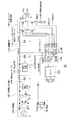
図3は、コントロールユニット30の回路構成の一例を示す図である。コントロールユニット30は、マイコン101と、検出回路102と、ソレノイド通電回路105と、蓄電コンデンサ106と、昇圧回路107と、発電回路108と、充電電圧制限回路109と、制限抵抗114と、ソレノイドバルブ駆動コンデンサ115と、通電電流検出抵抗120とを備えている。
FIG. 3 is a diagram illustrating an example of a circuit configuration of the
検出回路102は、水栓装置の使用者の人体を検出する。検出回路102は必ずしもセンサである必要はなく、水栓装置の制御条件となるものであれば、手動の操作スイッチやタイマなどでもよい。
The
ソレノイド通電回路105は、ソレノイド54に通電し、図2に示すプランジャ40を駆動する。ソレノイド54は、上述の通りバルブ23の開/閉状態の切替え時以外に電流を消費しないラッチング式のソレノイドである。ソレノイド通電回路105は、バルブ23の開/閉状態の切替えに応じて、ソレノイド54に流す電流の向きを切替えるHブリッジ回路である。例えば、バルブ23を閉状態から開状態へ切り替える際には、マイコン101はポートP01、P02、P03、P04からL、H、H、Lをそれぞれ出力し、矢印A1の向きに電流を流す。なお、“L”は論理ロウ、“H”は論理ハイを示す。一方、バルブ23を開状態から閉状態へ切り替える際には、マイコン101はポートP01、P02、P03、P04からH、L、L、Hをそれぞれ出力し、矢印A2の向きに電流を流す。尚、通常、ソレノイド通電回路105の通電電流は、マイコン101および検出回路102の消費電流よりも圧倒的に大きい。
The solenoid energization circuit 105 energizes the
発電部108は、水路に設けられた水力発電機でよい。発電部108で生成された電力は、充電電圧制限部109を介して蓄電コンデンサ106を充電する。電池18は、発電部108のバックアップとして機能する。充電電圧制限部109は、マイコン101等を保護するために、発電部108の出力電圧を所定電圧以下に制限している。
The power generation unit 108 may be a hydroelectric generator provided in the water channel. The electric power generated by the power generation unit 108 charges the storage capacitor 106 via the charging voltage limiting unit 109. The
昇圧回路107は、マイコン101の制御を受けて、蓄電コンデンサ106の電圧VCを電源電圧VDDへ昇圧して出力する。電圧VDDは、検出回路102、マイコン101等に印加される電源電圧として用いられる。
Under the control of the microcomputer 101, the booster circuit 107 boosts the voltage VC of the storage capacitor 106 to the power supply voltage VDD and outputs it. The voltage VDD is used as a power supply voltage applied to the
ソレノイドバルブ駆動コンデンサ115は、昇圧回路107から出力された電荷を蓄積し、ソレノイド54の通電時にソレノイド通電回路105へ電流を供給する。VLSは、ソレノイドバルブ駆動コンデンサ115がソレノイド通電回路105へ供給する電圧である。
The solenoid valve drive capacitor 115 accumulates the electric charge output from the booster circuit 107 and supplies a current to the solenoid energization circuit 105 when the
マイコン101は、昇圧前の電圧VCおよび供給電圧VLSに基づいて昇圧回路107およびソレノイド通電回路105のDUTYを制御する。DUTYは、単位時間に昇圧回路107またはソレノイド通電回路105を駆動させる時間の割合(駆動時間/(駆動時間+停止時間))を示す。DUTYを上げると、単位時間における昇圧回路107の出力電流、あるいは、単位時間におけるソレノイド54に流れる電流が多くなる。
電流検出抵抗120は、通電時にソレノイド54に流れるモニタ電流Imonを検出し、モニタ電流Imonを監視するために設けられている。マイコン101は、モニタ電流Imonを監視するために、ソレノイド54と電流検出抵抗120との間のノードNmonのモニタ電圧Vmonを監視する。ソレノイド54の抵抗値をRcとし、電流検出抵抗120の抵抗値をRrとすると、モニタ電流Imonは式1で表わされ、モニタ電圧Vmonは式2で表わされる。
VLS/(Rc+Rr) (式1)
Imon×Rr (式2)
尚、ソレノイド通電回路105のHブリッジのトランジスタ抵抗および配線抵抗は、RcおよびRrに比べて非常に小さいので考慮していない。抵抗値RcおよびRrはほぼ一定であるので、モニタ電圧Vmonは、モニタ電流Imonに比例すると考えてよい。従って、モニタ電圧Vmonを監視することは、モニタ電流Imonを監視することと等価である。
The microcomputer 101 controls the DUTY of the booster circuit 107 and the solenoid energization circuit 105 based on the pre-boost voltage VC and the supply voltage VLS. DUTY indicates a ratio of time for driving the booster circuit 107 or the solenoid energization circuit 105 per unit time (drive time / (drive time + stop time)). When DUTY is increased, the output current of the booster circuit 107 per unit time or the current flowing through the
The
VLS / (Rc + Rr) (Formula 1)
Imon × Rr (Formula 2)
Note that the transistor resistance and wiring resistance of the H-bridge of the solenoid energization circuit 105 are not considered because they are much smaller than Rc and Rr. Since the resistance values Rc and Rr are substantially constant, the monitor voltage Vmon may be considered to be proportional to the monitor current Imon. Therefore, monitoring the monitor voltage Vmon is equivalent to monitoring the monitor current Imon.
マイコン101は、AD(Analogue- Digital)変換部130と、比較部132と、記憶部134と、タイマ136とを備えている。AD変換部130は監視部であって、AD変換用ポートAD1から受信したモニタ電圧Vmonをデジタル値へ変換するように構成されている。これにより、モニタ電圧Vmonはマイコン101内で演算処理可能となる。以下、モニタ電圧Vmonは、デジタル変換後の電圧値として説明を進める。比較部132は、モニタ電圧Vmon等のパラメータを所定の閾値と比較するように構成されている。タイマ136は、クロックを計数するカウンタでよい。記憶部134は、モニタ電圧Vmon等のパラメータおよび閾値情報等を格納している。記憶部134は、ROM(Read Only Memory)またはRAM(Random Access Memory)でよい。記憶部134をRAMで構成した場合、閾値電圧および設定時間等の記憶部134に格納された情報は書き換え可能となる。
The microcomputer 101 includes an AD (Analogue-Digital) conversion unit 130, a
図4は、バルブ23の切替え時におけるモニタ電圧Vmonおよびプランジャ40への通電出力を示すグラフである。図4の上側にはモニタ電圧Vmonの経時変化を示し、その下側にはソレノイド54への通電出力を示す。
FIG. 4 is a graph showing the monitor voltage Vmon and the energization output to the
T0は、ソレノイド54への通電を開始する時点(以下、通電の始点)である。T10は、プランジャ40の移動開始時点である。T20は、ソレノイド54への通電を終了する時点(以下、通電の終点)である。なお、T20は、後述するようにプランジャ40の移動完了時点とほぼ同時、あるいは、その直後に設定することができる。△T10は、プランジャ40の移動開始時点T10から移動完了時点(即ち、通電の終点)T20までの移動時間である。
T0 is a time point when energization of the
ソレノイド54への通電の終点をプランジャ40の移動完了時点とほぼ一致させ、あるいは、その直後に設定することができる理由は次の通りである。
The reason why the end point of energization of the
通常、プランジャ40は、ソレノイド54に流れる電流(Imon)が或る閾値電流を超えたときに移動を開始する。プランジャ40の移動開始時にソレノイド54に流れる電流値を閾値電流I1とすると、閾値電流I1は、環境温度によらずほぼ一定である。即ち、プランジャ40の移動開始時にノードNmonの電圧を閾値電圧V1とすると、閾値電圧V1も、環境温度によらずほぼ一定である。従って、マイコン101は、モニタ電圧Vmonが所定の閾値電圧V1に達した時点T10をプランジャ40の移動開始時点と判断することができる。
Normally, the
また、プランジャ40の移動期間中において最も大きな電流を必要とする時点は、プランジャ40の移動開始時点である。その後、プランジャ40の移動を継続させるために必要最小限の電流がソレノイド54へ通電されている限り、プランジャ40は移動を継続することができる。従って、プランジャ40の移動開始後、プランジャ40の移動は、ソレノイド54への通電時間に依存する。
Further, the time point at which the largest current is required during the movement period of the
さらに、通常動作において、通電時間に対するモニタ電流Imonの変化量は、バルブ装置固有であり、バルブの開/閉を繰り返しても通電時間に対するモニタ電流Imonの変化量の傾向は同一である。従って、バルブ装置の構成が同じであれば、プランジャ40の移動時間△T10はほぼ一定であり、予め設定可能である。
このように、プランジャ40の移動開始時点T10はモニタ電圧Vmonから判断することができ、かつ、プランジャ40の移動時間△T10は予め設定可能であるので、プランジャ40の移動完了時点T20(T20=T10+△T10)も正確に把握することができる。即ち、通電の終点T20をプランジャ40の移動完了時点あるいはその直後に設定すれば、ソレノイド54への通電の終点をプランジャ40の移動完了時点とほぼ同時、あるいは、その直後に設定することができる。
Furthermore, in normal operation, the amount of change in the monitor current Imon with respect to the energization time is unique to the valve device, and the tendency of the amount of change in the monitor current Imon with respect to the energization time is the same even when the valve is repeatedly opened and closed. Therefore, if the configuration of the valve device is the same, the movement time ΔT10 of the
Thus, since the movement start time T10 of the
尚、モニタ電流Imonおよびモニタ電圧Vmon自体は、昇圧回路107からの供給電圧VLSの変動およびソレノイド54の環境温度によって変動する。しかし、モニタ電圧Vmonの変化は、モニタ電圧Vmonが閾値電圧V1へ到達するまでの時間(T0〜T10)を変化させるだけであり、プランジャ40は、モニタ電圧Vmonが閾値電圧V1に達した時点T10で移動を開始することに変りはない。従って、供給電圧VLSおよび環境温度が変動しても、マイコン101は、プランジャ40の移動開始時点T10を正確に検出することができる。
The monitor current Imon and the monitor voltage Vmon itself vary depending on the variation of the supply voltage VLS from the booster circuit 107 and the environmental temperature of the
以上のように、本実施形態によるバルブ装置は、プランジャ40の移動開始時点T10をモニタ電圧Vmon(モニタ電流Imon)によって検出し、その後、プランジャ40の移動完了時点T20を時点T10および設定時間△T10によって決定する。
As described above, the valve device according to the present embodiment detects the movement start time T10 of the
図5は、第1の実施形態によるバルブ装置の全体的な動作を示すフロー図である。図5に示すメインルーチンは、人体が検出されたときに遅滞なく吐水を開始し、人体が検出されなくなったときに遅滞なく止水するように、周期的に繰り返し実行される。 FIG. 5 is a flowchart showing the overall operation of the valve device according to the first embodiment. The main routine shown in FIG. 5 is repeatedly executed periodically so that water discharge starts without delay when a human body is detected, and water stops without delay when no human body is detected.
まず、マイコン101が検出部102を駆動する(S100)。検出部102が人体を検知した場合(S110のYES)、マイコン101は止水中であるか否かを判定する。前回のルーチンで人体が検出され、既に吐水状態となっている場合(S120のNO)、バルブ23の切替えは不要であるので、スタートへ戻る。止水状態である場合(S120のYES)には、開通電処理を行う(S130)。開通電処理は、バルブ23を閉状態から開状態へ切替える処理である。これにより、吐水が開始される。止水中か否かの判定は次のように行う。マイコン101内のRAMが、ソレノイド54への通電に関与する出力ポートP01〜P04の履歴を記憶する。その履歴により、現在のバルブ23の開/閉状態が判明する。尚、記憶部134がRAMで構成されている場合、このRAMは、記憶部134でよい。勿論、このRAMは、記憶部134とは別個のメモリであってもよい。
First, the microcomputer 101 drives the detection unit 102 (S100). When the
検出部102が人体を検知しなかった場合(S110のNO)、マイコン101は吐水中であるか否かを判定する。前回のこのルーチンの処理において人体が検出されず、既に止水状態となっている場合(S140のNO)、バルブ23の切替えは不要であるので、スタートへ戻る。一方、吐水状態である場合(S140のYES)には、閉通電処理を行う(S150)。吐水中か否かの判定は、止水中か否かの判定と同様に行われる。閉通電処理は、バルブ23を開状態から閉状態へ切替える処理である。これにより、吐水が停止される。スタートへ戻ると、図5のルーチンが繰り返される。
When the
図6は、図5に示す閉通電処理(S150)のフローを示す図である。図5のS150では、図6に示すサブルーチンが実行される。ステップS150の開始時点で、バルブ23は開状態である。まず、コントロールユニット30はソレノイド54への通電を開始する(S160)。この通電開始時は、図4の時点T0に該当する。このとき、マイコン101は、ポートP02、P04に接続されたトランジスタをオン状態に切り替え、ポートP01、P03に接続されたトランジスタをオフ状態に維持する。
FIG. 6 is a diagram showing a flow of the closing energization process (S150) shown in FIG. In S150 of FIG. 5, the subroutine shown in FIG. 6 is executed. At the start of step S150, the
マイコン101内の比較部132は、AD変換部130からモニタ電圧Vmonを受け取り、記憶部134から閾値電圧V1を受け取り、これらを比較する。モニタ電圧Vmonが閾値電圧V1よりも低い場合(S170のNO)、比較部132は、モニタ電圧Vmonと閾値電圧V1との比較を継続する。モニタ電圧Vmonが閾値電圧V1以上になった場合(S170のYES)、比較部132は、タイマ136を駆動させる駆動信号を出力する。
The
タイマ136は、比較部132から駆動信号を受け取り、計時を開始する(S180)。計時の開始時は、図4の時点T10に該当する。比較部132は、時点T10から現時点までの計測時間tと記憶部134から受け取った設定時間△T10とを比較する。計測時間tが設定時間△T10に満たない場合(S190のNO)、タイマ136は計時を継続する。計測時間tが設定時間△T10を経過した場合(S190のYES)、比較部132は、ソレノイド54への通電を停止させる停止信号を出力する。コントロールユニット30は停止信号に基づいてソレノイド54への通電動作を停止する(S195)。即ち、ポートP01〜P04に接続されたトランジスタを全てオフ状態にする。この通電停止時点は、図4のプランジャ40の移動完了時点T20に該当する。以上により、ステップS150の閉通電処理のサブルーチンが終了する。
The
開通電処理S130は、閉通電処理S150におけるソレノイド54への通電方向を逆にすればよい。開通電処理S130の設定時間△T10および閾値電圧V1が閉通電処理S150のそれらと異なっている場合には、開通電処理S130および閉通電処理S150のそれぞれについて、設定時間△T10および各閾値電圧V1を予め記憶部134に格納しておけばよい。そして、開通電処理S130では、比較部132およびタイマ136は、開通電処理S130用の閾値電圧V1および設定時間△T10を用いる。各開通電処理S130のその他のステップは、閉通電処理S150のステップと基本的に同様である。
In the open energization process S130, the energization direction to the
以上のように、第1の実施形態によるコントロールユニット30は、モニタ電圧Vmonおよび閾値電圧V1に基づいてプランジャ40の移動開始時点T10を判断し、プランジャ40の移動開始時点T10および移動時間△T10からソレノイド54への通電の終点T20を決定している。プランジャ40の移動開始時点のモニタ電圧を示す閾値電圧V1およびプランジャ40の移動時間△T10は、上述の通り、装置固有の定数であり、予め設定可能である。このため、通電の終点T20は、プランジャ40の移動完了時点とほぼ同時、あるいは、その直後に設定することができる。これにより、本実施形態によるバルブ装置は、プランジャ40の移動完了後の無駄な通電時間を可及的に短くし、ソレノイド54における無駄な消費電力を削減することができる。
As described above, the
尚、上記実施形態では、開通電処理S130および閉通電処理S150の両方において、同様の手法で通電の終点を決定していた。しかし、開通電処理S130には、特許文献1に記載されたボトム検知を適用してもよい。その理由は以下の通りである。開通電処理S130では、プランジャ40は磁石50に当たった瞬間に停止するが、閉通電処理S150では、プランジャ40はダイヤフラム弁20を押しながら比較的緩やかに移動を完了する。従って、開通電処理S130では、ソレノイド54に流れる電流の変曲点(ボトム)が明確に現れ易いが、閉通電処理S150では、ソレノイド54に流れる電流のボトムが不明確になる場合がある。このため、閉通電処理S150に特許文献1のボトム検知を適用した場合には、通電を時間で制御する機会が多くなる。特許文献1では、通電時間は、プランジャ40の移動完了時点よりも充分後に設定されている。従って、閉通電処理S150では消費電力が大きくなってしまう。一方、開通電処理S130ではボトムが明確に現れるので、消費電力の無駄は小さい。従って、閉通電処理S150に本実施形態を適用し、開通電処理S130に特許文献1のボトム検知を適用しても、本実施形態の効果を充分に発揮することができる。
In the above embodiment, the energization end point is determined by the same method in both the open energization process S130 and the close energization process S150. However, the bottom detection described in Patent Document 1 may be applied to the open energization process S130. The reason is as follows. In the opening energization process S130, the
第1の実施形態では、通電時間に対するモニタ電流Imonの変化量は、バルブ装置ごとに同一であるものとした。もし、通電時間に対するモニタ電流Imonの変化量が変化する場合には、後述の第4の実施形態のようにモニタ電流Imonを積算した電気量Qmonを用いてソレノイド54への通電時間を決定する手法、あるいは、第5の実施形態のように通電開始時点からプランジャ40の移動開始時点までの初期時間△Tiを用いてプランジャ40の移動時間を設定する手法を採用すればよい。
In the first embodiment, the amount of change in the monitor current Imon with respect to the energization time is the same for each valve device. If the change amount of the monitor current Imon with respect to the energization time changes, a method of determining the energization time to the
(第2の実施形態)
図7は、本発明に係る第2の実施形態に従ったコントロールユニット30に設けられた定電流制御部200の回路構成を示す図である。第2の実施形態によるバルブ装置は、定電流制御部200を含む点で第1の実施形態と異なる。第2の実施形態のその他の構成は、対応する第1の実施形態の構成と同様でよい。
(Second Embodiment)
FIG. 7 is a diagram showing a circuit configuration of the constant current control unit 200 provided in the
定電流制御部200は、ノードNmonと電流検出抵抗120との間に接続されており、ソレノイド54および電流検出抵抗120に定電流を流すように機能する。電流検出抵抗120と定電流制御部200との間のノードをNeとし、ノードNeの電圧をVeとする。電圧VeがVrefよりも低い場合、増幅器AMP1は、トランジスタTr200をオンにし、電圧Veを上昇させる。電圧VeがVrefよりも高い場合、増幅器AMPは、トランジスタTr200をオフにし、電圧Veを低下させる。従って、増幅器AMPは、電圧Veが参照電位Vrefにほぼ等しくなるようにトランジスタTr200を制御する。電圧Veが参照電圧Vrefに等しくなったときのモニタ電流Imonは、式3で表わされる。
Vref/Rr (式3)
Vref/Rrは一定値であるので、モニタ電流Imonは定電流値(Vref/Rr)に維持されるように制御される。
The constant current control unit 200 is connected between the node Nmon and the
Vref / Rr (Formula 3)
Since Vref / Rr is a constant value, the monitor current Imon is controlled to be maintained at a constant current value (Vref / Rr).
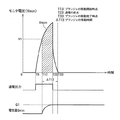
図8は、第2の実施形態によるバルブ23の切替え時におけるモニタ電圧Vmonおよびプランジャ40への通電出力を示すグラフである。第2の実施形態では、定電流値(Vref/Rr)は、閾値電流I1に等しくなるように設定され、モニタ電流Imonは閾値電流I1に等しくなるように制御される。つまり、閾値電流I1は、参照電圧Vrefまたは電流検出抵抗120の抵抗値Rrを調節することによって設定される。モニタ電流Imonを閾値電圧I1に等しくすることは、モニタ電圧Vmonを閾値電圧V1に等しくすることと同じである。従って、モニタ電圧Vmonは、図8に示すように、閾値電圧V1に等しくなるよう制御される。
FIG. 8 is a graph showing the monitor voltage Vmon and the energization output to the
例えば、時点T0において、ソレノイド54への通電が開始される。時点T11において、モニタ電圧Vmonが閾値電圧V1に達すると、プランジャ40は移動を開始する。時点T11からT21において、定電流制御部200によってモニタ電流Imonは閾値電流I1に維持されるため、モニタ電圧Vmonも閾値電圧V1に維持される。
For example, energization of the
その後、時点T21においてソレノイド54への通電を終了する。尚、通電の終点T21の設定手法は、第1の実施形態における通電の終点T20の設定手法と同様である。また、第2の実施形態のその他の動作は、図5および図6を参照して説明した第1の実施形態の動作と同様である。尚、図6のステップS190の括弧で示すように、計測時間tは設定時間△T11と比較される。
Thereafter, energization of the
上述の通り、プランジャ40の移動期間中において最も大きな電流を必要とする時点は、プランジャ40の移動開始時点であるので、閾値電流I1を超える電流は無駄な消費電流である。従って、第2の実施形態によるバルブ装置は、定電流制御部200を用いて電流Imonを閾値電流I1以下に制限することによって、無駄な消費電流をさらに削減しつつ、プランジャ40を確実に移動完了させることがきる。さらに、第2の実施形態は、上述した第1の実施形態の効果も得ることができる。
As described above, since the time point at which the largest current is required during the movement period of the
(第3の実施形態)
図9は、本発明に係る第3の実施形態によるバルブ23の切替え時におけるモニタ電圧Vmonおよびプランジャ40への通電出力を示すグラフである。第3の実施形態によるバルブ装置の基本的構成は、図1から図3に示すバルブ装置の構成と同様でよい。
(Third embodiment)
FIG. 9 is a graph showing the monitor voltage Vmon and the energization output to the
第3の実施形態では、モニタ電圧Vmonが閾値電圧V1に達した後、モニタ電圧Vmonを閾値電圧V1に維持するために、ソレノイド54への通電をDUTY制御する。
In the third embodiment, after the monitor voltage Vmon reaches the threshold voltage V1, in order to maintain the monitor voltage Vmon at the threshold voltage V1, the energization to the
例えば、時点T0において、ソレノイド54への通電が開始される。時点T12において、モニタ電圧Vmonが閾値電圧V1に達すると、プランジャ40は移動を開始する。時点T12からT22において、図3に示すマイコン101は、ソレノイド54への通電の停止と開始とを繰り返す。これにより、モニタ電圧Vmonが閾値電圧V1に維持される。即ち、モニタ電流Imonが閾値電流I1に維持される。
For example, energization of the
その後、時点T22において、ソレノイド54への通電を終了する。通電の終点T22の設定手法は、第1の実施形態における通電の終点T20の設定手法と同様である。また、第3の実施形態のその他の動作は、図5および図6を参照して説明した第1の実施形態の動作と同様である。
Thereafter, at time T22, energization of the
図10は、第3の実施形態の閉通電処理(S150)のフローを示す図である。尚、第3の実施形態によるバルブ装置の動作を示すメインルーチンは、図5に示すものと同様である。 FIG. 10 is a diagram illustrating a flow of the closing energization process (S150) of the third embodiment. The main routine showing the operation of the valve device according to the third embodiment is the same as that shown in FIG.
ステップS150のスタートからステップS380までの動作は、図6に示すステップS150のスタートからステップS180までの動作と同様である。 The operation from the start of step S150 to step S380 is the same as the operation from the start of step S150 to step S180 shown in FIG.
ステップS380の後、マイコン101がポートP01〜P04に接続されたトランジスタを全てオフ状態にする(S382)。これにより、ソレノイド54への通電が停止する。マイコン101は、この通電停止状態を、例えば、5μs間維持する(S384)。その後、マイコン101は、再度、通電を開始する(S386)。このとき、ソレノイド54への通電方向は、ステップS360におけるそれと同じである。さらに、マイコン101は、この通電状態を、例えば、5μs間維持する(S388)。ここで、ステップS384およびS388における通電停止状態あるいは通電状態の維持時間は、予め設定されおり、記憶部134に格納されている。タイマ136は、ステップS380における計時とは別に、通電停止状態あるいは通電状態にエンターしてからの時間を計測する。マイコン101は、タイマ136の計測時間が記憶部134に格納された所定の維持時間(例えば、5μs)に達したときに、ソレノイド通電回路105を通電停止状態から通電状態へあるいは通電状態から通電停止状態へ切替える。
After step S380, the microcomputer 101 turns off all the transistors connected to the ports P01 to P04 (S382). Thereby, the energization to the
ステップS382〜S388は、計測時間tが設定時間△T12に達するまで繰り返される。計測時間tが設定時間△T12に達した場合(S390のYES)、マイコン101は、ソレノイド54への通電動作を停止する(S395)。ステップS395の動作は、図6のステップS195の動作と同様である。この通電停止時点は、プランジャ40の移動完了時点T22に該当する。以上により、ステップS150の閉通電処理のサブルーチンが終了する。
また、図10のフローでは通電停止状態あるいは通電状態の維持時間は予め設定された時間であったが、この時間を可変にすることも可能である。例えば、モニタ電圧Vmonが閾値電圧V1未満のときは通電状態にし、モニタ電圧Vmonが閾値電圧V1以上のときは通電停止状態とすることで、モニタ電圧Vmonを閾値電圧V1に維持することができる。この処理は、ステップS382〜S388の代わりに実行すればよい。
Steps S382 to S388 are repeated until the measurement time t reaches the set time ΔT12. When the measurement time t reaches the set time ΔT12 (YES in S390), the microcomputer 101 stops the energization operation to the solenoid 54 (S395). The operation in step S395 is similar to the operation in step S195 in FIG. This energization stop time corresponds to the movement completion time T22 of the
Further, in the flow of FIG. 10, the energization stop state or the energization state maintaining time is a preset time, but this time can be made variable. For example, the monitor voltage Vmon can be maintained at the threshold voltage V1 by setting the energized state when the monitor voltage Vmon is lower than the threshold voltage V1, and by stopping the energization when the monitor voltage Vmon is equal to or higher than the threshold voltage V1. This process may be executed instead of steps S382 to S388.
このように、第3の実施形態では、モニタ電圧Vmonが閾値電圧V1に達した後、コントロールユニット30は、ソレノイド54への通電の停止と開始とを繰り返すことによってモニタ電圧Vmonを閾値電圧V1に維持する。これにより、バルブ装置は、定電流制御部200を設けることなく、モニタ電流Imonを閾値電流I1以下に制限することができる。その結果、第3の実施形態は、第2の実施形態と同様の効果を得ることができるとともに、コントロールユニット30の回路規模の増大を抑制することができる。
As described above, in the third embodiment, after the monitor voltage Vmon reaches the threshold voltage V1, the
(第4の実施形態)
図11は、本発明に係る第4の実施形態に従ったコントロールユニット30に設けられた電気量積算部400の回路構成を示す図である。第4の実施形態によるバルブ装置は、電気量積算部400を含む点で第1の実施形態と異なる。第4の実施形態のその他の構成は、対応する第1の実施形態の構成と同様でよい。
(Fourth embodiment)
FIG. 11 is a diagram showing a circuit configuration of the electric quantity integrating unit 400 provided in the
電気量積算部400は、増幅器AMP10、AMP20と、トランジスタTr400と、抵抗74と、コンデンサ75とを含む。電気量積算部400は、モニタ電圧Vmonを、増幅器AMP20とトランジスタTr400 と抵抗74とで電流に変換し、その変換電流を、増幅器AMP10とコンデンサ75と抵抗74とで積分する。電気量積算部400は、電流Imonを積分した電気量Qmonをマイコン101のAD変換用ポートAD2に出力する。AD変換部130は、モニタ電圧Vmonとは別に、電気量QmonをAD変換する。これにより、電気量Qmonはマイコン101内で演算処理可能となる。以下、電気量Qmonは、デジタル変換後の電気量として説明を進める。
The electric quantity integrating unit 400 includes amplifiers AMP10 and AMP20, a transistor Tr400, a
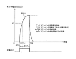
図12は、第4の実施形態によるバルブ23の切替え時におけるモニタ電圧Vmon、プランジャ40への通電出力および電気量Qmonを示すグラフである。第4の実施形態によるバルブ装置は、閾値電圧V1およびプランジャ40の移動時間△T13だけでなく、閾値電気量Q1も用いて通電の終点を決定する。
FIG. 12 is a graph showing the monitor voltage Vmon, the energization output to the
通常、プランジャ40の移動速度はソレノイド54に流れる電流Imonを大きくすると加速される。従って、プランジャ40の移動時間△T13内において、プランジャ40の移動開始後から積分された電気量Qmonが所定の閾値電気量Q1に達した時点で通電を停止したとしても、プランジャ40は移動速度が速いために通常よりも短い時間で移動完了することができる。閾値電気量Q1は、各バルブ装置固有のパラメータであるので、予め設定することができる。尚、閾値電気量Q1は、図12の斜線部分の面積で表わすことができる。従って、T13、T23およびVmonのラインで囲まれた部分の面積が所定の面積以上になった場合に、コントロールユニット30は、通電を停止すればよい。
Usually, the moving speed of the
例えば、時点T0において、ソレノイド54への通電が開始される。時点T13において、モニタ電圧Vmonが閾値電圧V1に達すると、プランジャ40は移動を開始する。それと同時に、電気量積算部400がモニタ電流Imonの積分を開始する。時点T23において、電気量Qmonが閾値電気量Q1に達すると、プランジャ40の移動時間△T13が経過していなくても、コントロールユニット30は、ソレノイド54への通電を終了する。
For example, energization of the
図13は、第4の実施形態の閉通電処理(S150)のフローを示す図である。尚、第4の実施形態によるバルブ装置の動作を示すメインルーチンは、図5に示すものと同様である。 FIG. 13 is a diagram illustrating a flow of the closing energization process (S150) of the fourth embodiment. The main routine showing the operation of the valve device according to the fourth embodiment is the same as that shown in FIG.
ステップS150のスタートからステップS480のうち計時開始の動作は、図6に示すステップS150のスタートからステップS180の動作と同様である。ステップS480において、タイマ136が計時を開始するとともに、電気量積算部400がモニタ電流Imonの積分を開始する。
The operation from the start of step S150 to the start of step S480 is the same as the operation from the start of step S150 to step S180 shown in FIG. In step S480, the
次に、マイコン101内の比較部132は、電気量積算部400からの電気量Qmonと閾値電気量Q1とを比較する(S485)。ステップS485は、タイマ136の計測時間tが設定時間△T13に達するまで周期的に繰り返される。
Next, the comparing
計測時間tが設定時間△T13に達する前に、電気量Qmonが閾値電気量Q1に達した場合(S485のYES)、コントロールユニット30は、ソレノイド54への通電動作を停止する(S495)。ステップS495の通電停止動作は、図6のステップS195の通電停止動作と同様である。この通電停止時点は、図12の時点T23に該当する。
If the electric quantity Qmon reaches the threshold electric quantity Q1 before the measurement time t reaches the set time ΔT13 (YES in S485), the
電気量Qmonが閾値電気量Q1に達する前に、計測時間tが設定時間△T13に達した場合(S490のYES)、コントロールユニット30は、ソレノイド54への通電動作を停止する(S495)。この通電停止時点は、図12の時点T33に該当する。以上により、ステップS150の閉通電処理のサブルーチンが終了する。
If the measurement time t reaches the set time ΔT13 before the electric quantity Qmon reaches the threshold electric quantity Q1 (YES in S490), the
このように、第4の実施形態では、プランジャ40の移動開始時点T13とプランジャの移動完了時点T33との間のいずれかの時点において電気量Qmonが閾値電気量Q1に達した場合、プランジャの移動完了時点T33まで通電を継続することなく、ソレノイド54への通電を終了する。従って、第4の実施形態は、無駄な消費電流をさらに削減しつつ、プランジャ40の移動を完了させることがきる。
Thus, in the fourth embodiment, when the electric quantity Qmon reaches the threshold electric quantity Q1 at any time point between the movement start time T13 of the
さらに、電気量Qmonが閾値電気量Q1に達する前に、プランジャの移動完了時点T33に達したとしても、ソレノイド54への通電を終了する。従って、第4の実施形態は、第1の実施形態と同様の効果を得ることができる。
Further, even if the plunger movement completion point T33 is reached before the electric quantity Qmon reaches the threshold electric quantity Q1, energization to the
(第5の実施形態)
図14は、本発明に係る第5の実施形態に従ったバルブ23の切替え時におけるモニタ電圧Vmonおよびプランジャ40への通電出力を示すグラフである。第5の実施形態によるバルブ装置の基本的構成は、図1から図3に示すバルブ装置の構成と同様でよい。
(Fifth embodiment)
FIG. 14 is a graph showing the monitor voltage Vmon and the energization output to the
第5の実施形態によるバルブ装置は、通電開始時点T0からプランジャ40の移動開始時点T14までの初期時間△Tiに基づいてプランジャ40の移動時間△T14を決定する。
The valve device according to the fifth embodiment determines the movement time ΔT14 of the
例えば、時間△Tiが短い場合、単位時間辺りのモニタ電流Imonの増加量が大きい。この場合、プランジャ40の移動中(T14〜T24)において、モニタ電流Imonが短時間で大きくなるため、プランジャ40の移動速度が速くなる。即ち、時間△Tiが短いと、プランジャ40の移動時間△T14が短くなる。従って、第5の実施形態では、時間△Tiの長さによって、プランジャ40の移動時間△T14を変更する。時間△Tiの長さによって、通電の終点を変更すると換言してもよい。
For example, when the time ΔTi is short, the increase amount of the monitor current Imon per unit time is large. In this case, during the movement of the plunger 40 (T14 to T24), the monitor current Imon increases in a short time, and thus the movement speed of the
図15は、第5の実施形態の閉通電処理(S150)のフローを示す図である。尚、第5の実施形態によるバルブ装置の動作を示すメインルーチンは、図5に示すものと同様である。 FIG. 15 is a diagram illustrating a flow of the closing energization process (S150) of the fifth embodiment. The main routine showing the operation of the valve device according to the fifth embodiment is the same as that shown in FIG.
まず、コントロールユニット30はソレノイド54への通電を開始する(S560)。これと同時に、タイマ136が計時を開始する。次に、比較部132がモニタ電圧Vmonを閾値電圧V1と比較する(S570)。モニタ電圧Vmonが閾値電圧V1よりも低い場合(S570のNO)、比較部132は、モニタ電圧Vmonと閾値電圧V1との比較を継続する。タイマ136も計時を継続する。このとき、時間△Tiはまだ判明していない。モニタ電圧Vmonが閾値電圧V1以上になった場合(S570のYES)、タイマ136が計時を停止する(S571)。このとき、プランジャ40の移動開始時点T14が決まるので、時間△Tiが判明する。
First, the
そして、比較部132は、時間△Tiと所定の閾値時間△Tαとを比較する(S572)。閾値時間△Tαは、予め設定された時間であり、記憶部134に格納しておく。時間△Tiが閾値時間△Tα以上の場合(S572のYES)、プランジャ40の移動速度が遅いと判断できるので、設定時間△T14を長く設定する(S574)。例えば、設定時間△T14は、2msに設定される。一方、時間△Tiが閾値時間△Tαより小さい場合(S572のNO)、プランジャ40の移動速度が速いと判断できるので、設定時間△T14を短く設定する(S576)。例えば、設定時間△T14は、1msに設定される。
Then, the
プランジャ40の移動開始と同時にタイマ136が計時を開始する(S580)。ステップS580〜S595の動作は、図6のステップS180〜S195の動作と同様である。ただし、ステップS590における設定時間△T14は、ステップS574またはS576のいずれかで設定された時間である。
Simultaneously with the start of movement of the
このように、第5の実施形態によるバルブ装置は、通電開始時点T0からプランジャ40の移動開始時点T14までの時間△Tiに基づいてプランジャ40の移動時間△T14を決定する。これにより、プランジャ40の移動速度に応じた移動時間△T14を設定することができるので、無駄な消費電力を削減しつつ、プランジャ40の移動を確実に完了させることがきる。
Thus, the valve device according to the fifth embodiment determines the movement time ΔT14 of the
第5の実施形態では、プランジャ40の移動時間△T14は2段階に設定される。しかし、プランジャ40の移動時間△T14は、3段階以上に設定されてもよい。この場合、ステップS572において、時間△Tiと比較する閾値時間は、複数設定される。これにより、プランジャ40の移動時間△T14を細かく設定できるので、さらに、無駄な消費電力を削減することがきる。
In the fifth embodiment, the movement time ΔT14 of the
さらに、マイコン101がプランジャ40の移動開始時点T14におけるモニタ電圧Vmonの傾き(dVmon/dT)を演算し、モニタ電圧Vmonの傾きに基づいてプランジャ40の移動時間△T14を設定してもよい。例えば、モニタ電圧Vmonの描く曲線の傾きに反比例するように、プランジャ40の移動時間△T14を設定してもよい。これにより、プランジャ40の移動時間△T14を任意に設定できるので、さらに、無駄な消費電力を省くことができる。
Furthermore, the microcomputer 101 may calculate the inclination (dVmon / dT) of the monitor voltage Vmon at the movement start time T14 of the
第5の実施形態は、第4の実施形態と組み合わせることができる。この場合、時点T24よりも前に電気量Qmonが閾値電気量Q1に達した場合、電気量Qmonが閾値電気量Q1に達した時点で通電を終了する。これにより、第5の実施形態は、第4の実施形態の効果をも得ることができる。 The fifth embodiment can be combined with the fourth embodiment. In this case, when the electric quantity Qmon reaches the threshold electric quantity Q1 before the time T24, the energization is ended when the electric quantity Qmon reaches the threshold electric quantity Q1. Thereby, 5th Embodiment can also acquire the effect of 4th Embodiment.
(第6の実施形態)
図16は、本発明に係る第6の実施形態に従ったバルブ23の切替え時におけるモニタ電圧Vmonおよびプランジャ40への通電出力を示すグラフである。第6の実施形態によるバルブ装置の基本的構成は、図1から図3に示すバルブ装置の構成と同様でよい。
(Sixth embodiment)
FIG. 16 is a graph showing the monitor voltage Vmon and the energization output to the
第6の実施形態によるバルブ装置は、予め設定された第1の閾値時間△Tβおよび第2の閾値時間△T20に基づいてショート故障またはオープン故障を検出する。第1の閾値時間△Tβは、通電開始時点T0からプランジャ40の移動開始までの時間の下限を示す。第2の閾値時間△T20は、通電開始時点T0からプランジャ40の移動開始までの時間の上限を示す。
The valve device according to the sixth embodiment detects a short-circuit failure or an open failure based on a first threshold time ΔTβ and a second threshold time ΔT20 set in advance. The first threshold time ΔTβ indicates the lower limit of the time from the energization start time T0 to the start of movement of the
例えば、図16に示すように、ソレノイド54への通電開始時点T0からモニタ電圧Vmonが閾値電圧V1に達する時点T10までの時間△Tiが第1の閾値時間△Tβ未満である場合、ショート故障が生じていると判断する。この場合、コントロールユニット30は、通電開始後、時間△Tiの経過時点で通電を停止する。
For example, as shown in FIG. 16, when the time ΔTi from the start time T0 of energization of the
一方、通電開始後、第2の閾値時間△T20が経過しても、モニタ電圧Vmonが閾値電圧V1に達しない場合、オープン故障が生じていると判断する。この場合、コントロールユニット30は、通電開始後、第2の閾値時間△T20の経過時点で通電を停止する。
On the other hand, if the monitor voltage Vmon does not reach the threshold voltage V1 even after the second threshold time ΔT20 has elapsed after the start of energization, it is determined that an open failure has occurred. In this case, after the start of energization, the
これにより、モニタ電圧Vmonが非常に短い時間で閾値電圧V1に達した場合、コントロールユニット30またはソレノイド54においてショート故障が生じていると判断できる。逆に、モニタ電圧Vmonが閾値電圧V1に達するまでに非常に長い時間がかかる場合、コントロールユニット30またはソレノイド54においてオープン故障が生じていると判断できる。
Accordingly, when the monitor voltage Vmon reaches the threshold voltage V1 in a very short time, it can be determined that a short circuit failure has occurred in the
図17は、第6の実施形態の閉通電処理(S150)のフローを示す図である。尚、第6の実施形態によるバルブ装置の動作を示すメインルーチンは、図5に示すものと同様である。 FIG. 17 is a diagram illustrating a flow of the closing energization process (S150) of the sixth embodiment. The main routine showing the operation of the valve device according to the sixth embodiment is the same as that shown in FIG.
まず、コントロールユニット30はソレノイド54への通電を開始する(S660)。これと同時に、タイマ136が計時を開始する。次に、比較部132がモニタ電圧Vmonを閾値電圧V1と比較する(S670)。モニタ電圧Vmonが閾値電圧V1よりも低い場合(S670のNO)、比較部132は、さらに、タイマ136における通電開始からの計測時間tiと第2の閾値時間△T20とを比較する(S672)。
First, the
計測時間tiが第2の閾値時間△T20以上になった場合(S672のYES)、バルブ装置がオープン故障であることをユーザに通知する(S674)。ユーザへの通知は、例えば、図3の検知部102のLEDを点滅させることで実行できる。
When the measurement time ti is equal to or longer than the second threshold time ΔT20 (YES in S672), the user is notified that the valve device is in an open failure (S674). The notification to the user can be executed by, for example, blinking the LED of the
一方、計測時間tiが第2の閾値時間△T20以上になる前に、ステップS670において、モニタ電圧Vmonが閾値電圧V1以上になった場合(S670のYES)、タイマ136が計時を停止する(S675)。これにより、時間△Tiが判明する。比較部132は、さらに、タイマ136における計測時間△Tiと第1の閾値時間△Tβとを比較する(S676)。
On the other hand, if the monitor voltage Vmon becomes equal to or higher than the threshold voltage V1 in step S670 before the measurement time ti becomes equal to or longer than the second threshold time ΔT20 (YES in S670), the
計測時間△Tiが第1の閾値時間△Tβ未満である場合(S676のNO)、バルブ装置がショート故障であることをユーザに通知する(S678)。ユーザへの通知は、例えば、図3の検知部102のLEDを点灯させればよい。一方、計測時間△Tiが第1の閾値時間△Tβ以上である場合(S676のYES)、バルブ装置にショート故障およびオープン故障が生じていないと判断して、タイマ136がさらに計時を開始する(S680)。その後のステップS580〜S595の動作は、図6のステップS180〜S195の動作と同様である。
When the measurement time ΔTi is less than the first threshold time ΔTβ (NO in S676), the user is notified that the valve device is short-circuited (S678). The notification to the user may be made, for example, by turning on the LED of the
このように、第6の実施形態によるバルブ装置は、通電開始時点T0からまでの時間△Tiまたはtiに基づいてショート故障およびオープン故障を検出することができる。 As described above, the valve device according to the sixth embodiment can detect the short-circuit failure and the open failure based on the time ΔTi or ti from the energization start time T0.
第6の実施形態は、第1から第5の実施形態のいずれかと組み合わせることができる。この場合、第1から第5の実施形態のいずれかの実施形態において、記憶部134が閾値時間Tβおよび△T20を予め格納し、タイマ136が通電開始からの時間tiを計測する。比較部132は時間△Tiと△Tβとの比較および時間tiと△T20との比較を実行すればよい。これにより、第6の実施形態は、第1から第5の実施形態のいずれかの効果をも得ることができる。
The sixth embodiment can be combined with any of the first to fifth embodiments. In this case, in any one of the first to fifth embodiments, the storage unit 134 stores the threshold times Tβ and ΔT20 in advance, and the
16・・・バルブユニット(バルブ装置)
20・・・ダイヤフラム弁(弁体)
30・・・コントロールユニット(制御部)
40・・・プランジャ
54・・・ソレノイドコイル
101・・・マイコン
105・・・ソレノイド通電回路
120・・・電流検出抵抗
130・・・AD変換部(監視部)
132・・・比較部
134・・・記憶部
136・・・タイマ部
200・・・定電流制御部
400・・・電気量積算部
Imon・・・モニタ電流
Vmon・・・モニタ電圧
Qmon・・・モニタ電気量
I1・・・閾値電流
V1・・・閾値電圧
Q1・・・閾値電気量
16 ... Valve unit (valve device)
20 ... Diaphragm valve (valve)
30 ... Control unit (control unit)
40 ...
132 ... Comparison unit 134 ...
Claims (9)
前記制御部は、
通電時に前記ソレノイドコイルを流れる電流または該電流に応じた電圧を監視する監視部と、
前記電流または前記電圧が所定電流値または所定電圧値に達した時点から計時するタイマ部と、
前記所定電流値または前記所定電圧値を記憶する記憶部とを備え、
前記電流または前記電圧が前記所定電流値または前記所定電圧値に達した時点から所定時間の経過後に、前記ソレノイドコイルへの通電を停止することを特徴とするバルブ装置。 A latching-type valve device comprising a plunger that moves by energizing the solenoid coil, a valve element that is driven to open and close the flow path by the movement of the plunger, and a control unit that controls energization to the solenoid coil Because
The controller is
A monitoring unit for monitoring a current flowing through the solenoid coil when energized or a voltage corresponding to the current;
A timer unit for timing from the time when the current or the voltage reaches a predetermined current value or a predetermined voltage value;
A storage unit for storing the predetermined current value or the predetermined voltage value;
A valve device, wherein energization of the solenoid coil is stopped after a predetermined time has elapsed since the current or the voltage reached the predetermined current value or the predetermined voltage value.
前記電流または前記電圧が所定電流値または所定電圧値に達した時点以降、前記ソレノイドコイルへの通電の停止と開始とを繰り返すことによって前記電流または前記電圧を前記所定電流値または所定電圧値に維持することを特徴とする請求項2に記載のバルブ装置。 The controller is
After the current or voltage reaches a predetermined current value or voltage value, the current or voltage is maintained at the predetermined current value or voltage value by repeatedly stopping and starting energization of the solenoid coil. The valve device according to claim 2, wherein:
前記所定時間の経過より前に前記積算電気量が所定の閾値電気量に達した場合、該積算電気量が前記閾値電気量に達した時点で前記ソレノイドコイルへの通電を停止することを特徴とする請求項1に記載のバルブ装置。 The control unit further includes an integration unit that calculates an integrated electric quantity obtained by integrating the current supplied to the solenoid coil after the time when the current or the voltage reaches a predetermined current value or a predetermined voltage value.
When the integrated electric quantity reaches a predetermined threshold electric quantity before the lapse of the predetermined time, the energization to the solenoid coil is stopped when the integrated electric quantity reaches the threshold electric quantity. The valve device according to claim 1.
前記初期時間に基づいて前記所定時間を変更することを特徴とする請求項1または請求項4に記載のバルブ装置。 The timer unit measures an initial time from the time when the energization to the solenoid coil is started to the time when the current or the voltage reaches the predetermined current value or the predetermined voltage value,
The valve device according to claim 1 or 4, wherein the predetermined time is changed based on the initial time.
前記初期時間が予め設定された第1の閾値時間よりも小さい場合、前記制御部は、当該バルブ装置内において故障が生じていることをユーザに通知し、前記ソレノイドコイルへの通電を停止することを特徴とする請求項1から請求項5のいずれかに記載のバルブ装置。 The timer unit measures an initial time from the time when the energization to the solenoid coil is started to the time when the current or the voltage reaches the predetermined current value or the predetermined voltage value,
When the initial time is shorter than a preset first threshold time, the control unit notifies the user that a failure has occurred in the valve device and stops energization of the solenoid coil. The valve device according to any one of claims 1 to 5, wherein:
前記ソレノイドコイルへの通電を開始した時点から予め設定された第2の閾値時間の経過までに、前記電流または前記電圧が前記所定電流値または前記所定電圧値に達しない場合、前記制御部は、当該バルブ装置内において故障が生じていることをユーザに通知し、前記ソレノイドコイルへの通電を停止すると判断することを特徴とする請求項1から請求項6のいずれかに記載のバルブ装置。 The timer unit starts measuring time from the start of energization of the solenoid coil,
When the current or the voltage does not reach the predetermined current value or the predetermined voltage value from when the energization to the solenoid coil is started until the elapse of a preset second threshold time, the control unit, The valve device according to any one of claims 1 to 6, wherein the valve device is notified that a failure has occurred in the valve device, and is determined to stop energization of the solenoid coil.
前記所定電圧値は、前記プランジャの移動開始時に前記ソレノイドコイルに供給されている電流値に対応する電圧値であることを特徴とする請求項1に記載のバルブ装置。 The predetermined current value is a current value supplied to the solenoid coil at the start of movement of the plunger,
The valve device according to claim 1, wherein the predetermined voltage value is a voltage value corresponding to a current value supplied to the solenoid coil at the start of movement of the plunger.
前記制御部は通電時に前記ソレノイドコイルへ供給される電流または該電流に応じた電圧を監視し、
前記制御部は前記電流または前記電圧が所定電流値または所定電圧値に達した時点から計時し、
前記電流または前記電圧が所定電流値または所定電圧値に達した時点から所定時間の経過後に、前記制御部は前記ソレノイドコイルへの通電を停止することを具備したことを特徴とするバルブ装置の駆動方法。 A latching-type valve device comprising a plunger that moves by energizing the solenoid coil, a valve element that is driven to open and close the flow path by the movement of the plunger, and a control unit that controls energization to the solenoid coil Driving method,
The control unit monitors a current supplied to the solenoid coil during energization or a voltage corresponding to the current,
The control unit counts the time when the current or the voltage reaches a predetermined current value or a predetermined voltage value,
Driving the valve device, wherein the control unit stops energizing the solenoid coil after a predetermined time has elapsed since the current or the voltage reached a predetermined current value or a predetermined voltage value. Method.
Priority Applications (1)
| Application Number | Priority Date | Filing Date | Title |
|---|---|---|---|
| JP2009223414A JP5489062B2 (en) | 2009-09-28 | 2009-09-28 | Valve device and driving method thereof |
Applications Claiming Priority (1)
| Application Number | Priority Date | Filing Date | Title |
|---|---|---|---|
| JP2009223414A JP5489062B2 (en) | 2009-09-28 | 2009-09-28 | Valve device and driving method thereof |
Publications (2)
| Publication Number | Publication Date |
|---|---|
| JP2011069481A true JP2011069481A (en) | 2011-04-07 |
| JP5489062B2 JP5489062B2 (en) | 2014-05-14 |
Family
ID=44014931
Family Applications (1)
| Application Number | Title | Priority Date | Filing Date |
|---|---|---|---|
| JP2009223414A Expired - Fee Related JP5489062B2 (en) | 2009-09-28 | 2009-09-28 | Valve device and driving method thereof |
Country Status (1)
| Country | Link |
|---|---|
| JP (1) | JP5489062B2 (en) |
Cited By (2)
| Publication number | Priority date | Publication date | Assignee | Title |
|---|---|---|---|---|
| WO2016067742A1 (en) * | 2014-10-30 | 2016-05-06 | 日機装エイコー株式会社 | Control device and control method for electromagnetic reciprocating pump |
| JP2020159384A (en) * | 2019-03-25 | 2020-10-01 | Toto株式会社 | Solenoid valve device and water discharge device |
Citations (6)
| Publication number | Priority date | Publication date | Assignee | Title |
|---|---|---|---|---|
| JPS6343081A (en) * | 1986-08-06 | 1988-02-24 | Hitachi Constr Mach Co Ltd | Monitoring device for operating state of solenoid operated valve |
| JPS63180497U (en) * | 1987-05-15 | 1988-11-22 | ||
| JPH0974813A (en) * | 1995-09-12 | 1997-03-25 | Iseki & Co Ltd | Hydraulic control equipment for agricultural machines |
| JPH09100938A (en) * | 1995-10-05 | 1997-04-15 | Denso Corp | Solenoid valve drive |
| JP2000145566A (en) * | 1998-11-10 | 2000-05-26 | Kokusan Denki Co Ltd | Driving method and driving device for injector for internal combustion engine |
| JP3564906B2 (en) * | 1996-11-29 | 2004-09-15 | 東陶機器株式会社 | Solenoid drive device, valve device and automatic water supply device using the same |
-
2009
- 2009-09-28 JP JP2009223414A patent/JP5489062B2/en not_active Expired - Fee Related
Patent Citations (6)
| Publication number | Priority date | Publication date | Assignee | Title |
|---|---|---|---|---|
| JPS6343081A (en) * | 1986-08-06 | 1988-02-24 | Hitachi Constr Mach Co Ltd | Monitoring device for operating state of solenoid operated valve |
| JPS63180497U (en) * | 1987-05-15 | 1988-11-22 | ||
| JPH0974813A (en) * | 1995-09-12 | 1997-03-25 | Iseki & Co Ltd | Hydraulic control equipment for agricultural machines |
| JPH09100938A (en) * | 1995-10-05 | 1997-04-15 | Denso Corp | Solenoid valve drive |
| JP3564906B2 (en) * | 1996-11-29 | 2004-09-15 | 東陶機器株式会社 | Solenoid drive device, valve device and automatic water supply device using the same |
| JP2000145566A (en) * | 1998-11-10 | 2000-05-26 | Kokusan Denki Co Ltd | Driving method and driving device for injector for internal combustion engine |
Cited By (4)
| Publication number | Priority date | Publication date | Assignee | Title |
|---|---|---|---|---|
| WO2016067742A1 (en) * | 2014-10-30 | 2016-05-06 | 日機装エイコー株式会社 | Control device and control method for electromagnetic reciprocating pump |
| JP2016089647A (en) * | 2014-10-30 | 2016-05-23 | 日機装エイコー株式会社 | Control device and control method for electromagnetic reciprocating pump |
| JP2020159384A (en) * | 2019-03-25 | 2020-10-01 | Toto株式会社 | Solenoid valve device and water discharge device |
| JP7307878B2 (en) | 2019-03-25 | 2023-07-13 | Toto株式会社 | Solenoid valve device and water discharge device |
Also Published As
| Publication number | Publication date |
|---|---|
| JP5489062B2 (en) | 2014-05-14 |
Similar Documents
| Publication | Publication Date | Title |
|---|---|---|
| US4742583A (en) | Water supply control apparatus | |
| TWI410577B (en) | Solenoid valve driving circuit, solenoid valve, and solenoid valve driving method | |
| US6305662B1 (en) | Reduced-energy-consumption actuator | |
| US6293516B1 (en) | Reduced-energy-consumption actuator | |
| EP2450491A1 (en) | Automatic sensing system and method | |
| US7903383B2 (en) | Solenoid valve driving circuit and solenoid valve | |
| US7813101B2 (en) | Solenoid-operated valve actuating controller | |
| KR100892210B1 (en) | Mode transition control method and circuit for a charge pump | |
| JP5489062B2 (en) | Valve device and driving method thereof | |
| WO1999013482A1 (en) | Controller for relay | |
| JP2017179742A (en) | Toilet bowl cleaning device | |
| JP2011089551A (en) | Valve device and method for driving the same | |
| JP2011012515A (en) | Faucet device | |
| JP3564906B2 (en) | Solenoid drive device, valve device and automatic water supply device using the same | |
| JP7037715B2 (en) | Toilet bowl cleaning device | |
| US20080209622A1 (en) | Electronic toilet tank monitor utilizing a bistable latching solenoid control circuit | |
| KR100921228B1 (en) | Pump control method | |
| JP2014129847A (en) | Valve driving device | |
| JP2858686B2 (en) | Toilet bowl cleaning equipment | |
| JPH0771064A (en) | Feed-water controller | |
| TW202538192A (en) | Signal output circuit and drive control method for solenoid valve | |
| WO2026033013A1 (en) | Detecting a toggle of power on a power line | |
| JP2020159384A (en) | Solenoid valve device and water discharge device | |
| CN106642557A (en) | Water tank water discharge switch noise reduction control method and system and air conditioner | |
| JPH0358612B2 (en) |
Legal Events
| Date | Code | Title | Description |
|---|---|---|---|
| A621 | Written request for application examination |
Free format text: JAPANESE INTERMEDIATE CODE: A621 Effective date: 20120914 |
|
| A977 | Report on retrieval |
Free format text: JAPANESE INTERMEDIATE CODE: A971007 Effective date: 20130606 |
|
| A131 | Notification of reasons for refusal |
Free format text: JAPANESE INTERMEDIATE CODE: A131 Effective date: 20130617 |
|
| A521 | Written amendment |
Free format text: JAPANESE INTERMEDIATE CODE: A523 Effective date: 20130808 |
|
| TRDD | Decision of grant or rejection written | ||
| A01 | Written decision to grant a patent or to grant a registration (utility model) |
Free format text: JAPANESE INTERMEDIATE CODE: A01 Effective date: 20140203 |
|
| R150 | Certificate of patent or registration of utility model |
Ref document number: 5489062 Country of ref document: JP Free format text: JAPANESE INTERMEDIATE CODE: R150 |
|
| A61 | First payment of annual fees (during grant procedure) |
Free format text: JAPANESE INTERMEDIATE CODE: A61 Effective date: 20140216 |
|
| LAPS | Cancellation because of no payment of annual fees |