JP2010522903A - Multifocal lens with progressive optical power region and discontinuity - Google Patents
Multifocal lens with progressive optical power region and discontinuity Download PDFInfo
- Publication number
- JP2010522903A JP2010522903A JP2010501284A JP2010501284A JP2010522903A JP 2010522903 A JP2010522903 A JP 2010522903A JP 2010501284 A JP2010501284 A JP 2010501284A JP 2010501284 A JP2010501284 A JP 2010501284A JP 2010522903 A JP2010522903 A JP 2010522903A
- Authority
- JP
- Japan
- Prior art keywords
- optical power
- lens
- zone
- region
- approximately
- Prior art date
- Legal status (The legal status is an assumption and is not a legal conclusion. Google has not performed a legal analysis and makes no representation as to the accuracy of the status listed.)
- Pending
Links
Images


Classifications
-
- G—PHYSICS
- G02—OPTICS
- G02C—SPECTACLES; SUNGLASSES OR GOGGLES INSOFAR AS THEY HAVE THE SAME FEATURES AS SPECTACLES; CONTACT LENSES
- G02C7/00—Optical parts
- G02C7/02—Lenses; Lens systems ; Methods of designing lenses
- G02C7/06—Lenses; Lens systems ; Methods of designing lenses bifocal; multifocal ; progressive
- G02C7/061—Spectacle lenses with progressively varying focal power
- G02C7/063—Shape of the progressive surface
-
- G—PHYSICS
- G02—OPTICS
- G02C—SPECTACLES; SUNGLASSES OR GOGGLES INSOFAR AS THEY HAVE THE SAME FEATURES AS SPECTACLES; CONTACT LENSES
- G02C7/00—Optical parts
- G02C7/02—Lenses; Lens systems ; Methods of designing lenses
- G02C7/06—Lenses; Lens systems ; Methods of designing lenses bifocal; multifocal ; progressive
- G02C7/061—Spectacle lenses with progressively varying focal power
- G02C7/063—Shape of the progressive surface
- G02C7/066—Shape, location or size of the viewing zones
-
- G—PHYSICS
- G02—OPTICS
- G02C—SPECTACLES; SUNGLASSES OR GOGGLES INSOFAR AS THEY HAVE THE SAME FEATURES AS SPECTACLES; CONTACT LENSES
- G02C2202/00—Generic optical aspects applicable to one or more of the subgroups of G02C7/00
- G02C2202/16—Laminated or compound lenses
-
- G—PHYSICS
- G02—OPTICS
- G02C—SPECTACLES; SUNGLASSES OR GOGGLES INSOFAR AS THEY HAVE THE SAME FEATURES AS SPECTACLES; CONTACT LENSES
- G02C2202/00—Generic optical aspects applicable to one or more of the subgroups of G02C7/00
- G02C2202/20—Diffractive and Fresnel lenses or lens portions
Abstract
【課題】累進光学パワー領域と不連続部を有している多焦点レンズを提供する。
【解決手段】本発明の実施形態は、大概球状パワー領域と累進光学パワー領域とを有している多焦点レンズに関する。本発明の実施形態は、これらの領域のおのおのの適切なアラインメントと配置、領域のおのおのによって提供される光学パワーの量、累進光学パワー領域の光学設計、および領域のおのおののサイズと形を提供する。これらの設計パラメータの組み合わせは、従来のPALsと比較して、より広いチャンネル幅とより短いチャンネル長の両方のほかに、少ない不所望な非点収差とひずみを有している光学設計を与える。本発明の実施形態はまた新規な発明遠中距離ゾーンを提供し得、レンズのゾーン内に視力の向上した鉛直安定性を提供し得る。A multifocal lens having a progressive optical power region and a discontinuous portion is provided.
Embodiments of the present invention relate to a multifocal lens having a generally spherical power region and a progressive optical power region. Embodiments of the present invention provide the proper alignment and placement of each of these regions, the amount of optical power provided by each of the regions, the optical design of the progressive optical power region, and the size and shape of each of the regions. . The combination of these design parameters provides an optical design that has less unwanted astigmatism and distortion, as well as both wider channel width and shorter channel length, compared to conventional PALs. Embodiments of the present invention may also provide a novel inventive far-medium distance zone, which may provide improved visual stability within the lens zone.
Description
関連出願への相互参照
この出願は、「累進光学パワー領域と不連続部を有している多焦点レンズ」と題する2007年12月25日に提出された米国シリアル番号11/964,030の一部継続出願であり、それらは参照によりそのままここに組み込まれる。
Cross Reference to Related Application This application is a part of US
この出願は以下の仮出願から優先権を請求し、またそれらをそのまま参照により組み入れる。 This application claims priority from the following provisional applications and incorporates them by reference in their entirety.
「不連続部を有している複合先進累進追加レンズ」と題する2007年3月29日に提出された米国シリアル番号60/906,211、
「累進レンズ領域を与える低追加パワー・カーブに関連した精巧円環状&球状湾曲」と題する2007年6月7日に提出された米国シリアル番号60/924,975、
「近方および中間視力の矯正用の複合光学部品」と題する2007年8月1日に提出された米国シリアル番号60/935,226、
「強化多重焦点眼鏡レンズを生成する道具類のダイヤモンド・ターニング」と題する2007年8月16日に提出された米国シリアル番号60/935,492、
「連続的光学パワーを備えた先進レンズ」と題する2007年8月17日に提出された米国シリアル番号60/935,573、
「連続的光学パワーを備えた先進多焦点レンズ」と題する2007年8月20日に提出された米国シリアル番号60/956,813、および
「洗練強化多重焦点」と題する2007年9月5日に提出された米国シリアル番号60/970,024。
US
US
US
US Serial No. 60 / 935,492, filed August 16, 2007, entitled “Diamond Turning of Tools to Generate Enhanced Multifocal Eyeglass Lenses”,
US
US
発明の背景
発明の分野
本発明は、目の上、中または近くで利用される多焦点眼用レンズ、レンズ設計、レンズ・システム、およびアイウェア製品またはデバイスに関する。より具体的には、本発明は、ほとんどの場合、累進追加レンズに関連する不所望なひずみ、不所望な非点収差および視力妥協を着用者のまさに許容範囲へ低減する多焦点眼用レンズ、レンズ設計、レンズ・システムおよびアイウェア製品に関する。
BACKGROUND OF THE INVENTION Field of the Invention The present invention relates to multifocal ophthalmic lenses, lens designs, lens systems, and eyewear products or devices utilized on, in or near the eye. More specifically, the present invention is a multifocal ophthalmic lens that reduces the unwanted distortion, unwanted astigmatism and vision compromise most often associated with progressive addition lenses to the very tolerance of the wearer, It relates to lens design, lens systems and eyewear products.
関連技術の説明
老眼は、加齢にしばしば伴う人間の目の水晶体の調節の損失である。この調節の損失はまず、近距離物体への合焦不能につながり、それから中距離物体への合焦不能につながる。老眼を矯正するための標準的用具は多焦点眼用レンズである。多焦点レンズは、ある距離範囲にわたって合焦問題を矯正するための一つを超える焦点距離(すなわち光学パワー)を有するレンズである。多焦点眼用レンズは、異なる光学パワーの領域へのレンズエリアの分割によって働く。一般に、レンズの上部部分に配置された比較的広いエリアは、もしあれば、遠距離視力障害を矯正する。レンズのボトムに配置された狭いエリアは、老眼によって引き起こされる近距離視力障害を矯正するための追加光学パワーを提供する。多焦点レンズはまたレンズの中央部近くに配置された領域を含み得、それは、中距離視力障害を矯正するための追加光学パワーを提供する。多焦点レンズは、連続または不連続の光学パワーを作り出す連続または不連続表面で構成され得る。
Description of Related Art Presbyopia is a loss of lens accommodation in the human eye that often accompanies aging. This loss of adjustment first leads to the inability to focus on close-range objects and then the inability to focus on medium-range objects. A standard tool for correcting presbyopia is a multifocal ophthalmic lens. A multifocal lens is a lens that has more than one focal length (ie, optical power) to correct a focusing problem over a range of distances. Multifocal ophthalmic lenses work by dividing the lens area into regions of different optical power. In general, a relatively large area located in the upper portion of the lens, if any, corrects long distance vision impairment. A narrow area located at the bottom of the lens provides additional optical power to correct near vision impairment caused by presbyopia. A multifocal lens may also include an area located near the center of the lens, which provides additional optical power to correct medium distance vision impairment. Multifocal lenses can be composed of continuous or discontinuous surfaces that produce continuous or discontinuous optical power.
異なる光学パワーの領域間の推移は、二焦点および三焦点レンズの場合であるように急で不連続であるか、累進追加レンズの場合であるように滑らかで連続的であるかのいずれかであり得る。累進追加レンズは、レンズの遠距離ゾーンからレンズの下部部分の近距離ゾーンへ連続的に増大する正の屈折光学パワーの勾配を備える多焦点レンズの一種である。光学パワーのこの累進は、レンズのフィッティング・クロスまたはフィッティング・ポイントとして知られているところまたはその近くから一般に始まり、全追加パワーがレンズの近距離ゾーンに実現されるまで続く。従来および最新の累進追加レンズは、光学パワーのこの累進を作り出すために形作られたレンズの一方または両外側表面の表面トポグラフィを利用する。累進追加レンズは光産業内では複数のときはPALsとしてまた単数のときはPALとして知られている。PALsは、従来の二焦点および三焦点レンズを超えて有利である。それは、それらがユーザーに、連続的視力矯正を有する線がなく見場がよく快い多焦点レンズを提供し得、またユーザーの焦点が遠距離にある物体から近距離にある物体に移るまたはその逆のときに知覚画像乱れを与え得るからである。 The transition between regions of different optical power is either steep and discontinuous, as in bifocal and trifocal lenses, or smooth and continuous as in progressive addition lenses. possible. A progressive addition lens is a type of multifocal lens with a positive refractive optical power gradient that continuously increases from the far zone of the lens to the near zone of the lower portion of the lens. This progression of optical power generally begins at or near what is known as the lens fitting cross or fitting point and continues until all the additional power is achieved in the lens's near-field zone. Conventional and modern progressive addition lenses utilize the surface topography of one or both outer surfaces of the lens shaped to create this progression of optical power. Progressive addition lenses are known as PALs when there are a plurality of progressive addition lenses and as PAL when there is a singular number. PALs are advantageous over conventional bifocal and trifocal lenses. It can provide the user with a multifocal lens that has good visibility with no lines with continuous vision correction, and the user's focus moves from a distant object to a close object or vice versa. This is because the perceived image may be disturbed at the time.
PALはいま、老眼用の矯正器としてアメリカ内および世界の至る所で広く受け入れられ、はやっているとは言え、それらはまた重大な視力妥協を有する。これらの妥協は、これらに限定されないが、不所望な非点収差、ひずみ、およびスイムを含む。これらの視力妥協は、ユーザーの水平視野幅に影響し得、それは、与えられた距離に合焦しながら、ユーザーが左右を見るときに、明瞭に見え得る視界の幅である。したがって、中距離に合焦するとき、PALsは狭い水平視野幅を有し得、それは、コンピューター・スクリーンの広い部分を見ることを困難にし得る。同様に、近距離に合焦するとき、PALsは狭い水平視野幅を有し得、それは、本または新聞のページ全体を見ることを困難にし得る。遠距離視力も同様に影響され得る。PALsはまた、レンズのひずみのために着用者がスポーツをすることを困難し得る。これらの制限に加えて、PALsの多くの着用者は、レンズのおのおのに存在するひずみのために(しばしば「スイム」と呼ばれる)視覚運動として知られる不快な影響を経験する。実際、多くの人々が、この結果からの不快のためにそのようなレンズを着用することを拒絶する。 Although PAL is now widely accepted and doing as a corrector for presbyopia throughout the United States and throughout the world, they also have serious vision compromises. These compromises include, but are not limited to, unwanted astigmatism, distortion, and swim. These vision compromises can affect the user's horizontal viewing width, which is the width of the field of view that can be clearly seen when the user looks left and right while focusing on a given distance. Thus, when focusing on medium distances, PALs can have a narrow horizontal field of view, which can make it difficult to see a large portion of the computer screen. Similarly, when focusing on short distances, PALs can have a narrow horizontal field of view, which can make it difficult to view an entire book or newspaper page. Far vision can be affected as well. PALs can also make it difficult for the wearer to play sports due to lens distortion. In addition to these limitations, many wearers of PALs experience an unpleasant effect known as visual movement (often referred to as “swimming”) because of the distortion present in each of the lenses. In fact, many people refuse to wear such lenses because of discomfort from this result.
老眼の個人の近距離光学パワー必要を考慮するとき、必要とされる近距離光学パワーの量は、個人が彼または彼女の目の中に残した協調的振幅(近距離合焦能力)の量に反比例する。一般に、個人が加齢するにつれて協調的振幅の量は減少する。協調的振幅はまた、さまざまな健康上の理由で減少し得る。したがって、加齢してより老眼になるにつれて、近距離および中距離に合焦する能力を矯正するために必要とされる光学パワーは、必要屈折光学パワーがより強くなる。近および中距離光学パワーは通常は「追加パワー」または「追加的光学パワー」に関して述べられる。追加パワーは、遠距離視力矯正を超える光学パワーの量である。追加パワーは、通常は適切な近距離視力矯正を達成するために遠距離視力矯正に加えられる光学パワーを指す。たとえば、ある人が、遠距離視野のために−1.00Dの光学パワー矯正を、また+2.00Dの近距離追加パワーを有するならば、そのような個人は近距離視野のために+1.00Dの光学パワー矯正を有すると呼ばれる。 When considering the near-field optical power requirement of a presbyopic individual, the amount of near-field optical power required is the amount of cooperative amplitude (short-range focusing ability) that the individual left in his or her eye Inversely proportional to In general, the amount of cooperative amplitude decreases as an individual ages. The cooperative amplitude can also be reduced for a variety of health reasons. Thus, as the person becomes older and becomes more presbyopic, the optical power required to correct the ability to focus on near and medium distances becomes more necessary refractive optical power. Near and medium range optical power is usually described in terms of “additional power” or “additional optical power”. The additional power is the amount of optical power that goes beyond far vision correction. Additional power refers to the optical power that is normally applied to the far vision correction to achieve proper near vision correction. For example, if a person has an optical power correction of -1.00 D for a far field of view and a short distance additional power of +2.00 D, such an individual will have +1.00 D for a near field of view. Called to have optical power correction.
二人の個人の異なる近距離追加パワー必要性を比較することによって、各個人の近点合焦必要性を直接比較することが可能である。ただ単に例として、45歳の個人は、近点距離で明瞭に見えるために+1.00Dの近距離追加パワーを必要とし得、一方、80歳の個人は、同じ近点距離で明瞭に見えるために+2.75Dないし+3.50Dの近距離追加パワーを必要とし得る。PALsの視力妥協の程度は屈折追加パワーとともに増大するので、より高度な老眼の個々は、より大きな視力妥協を受けるだろう。上記の例では、45歳である個人は、80歳である個人よりも、彼または彼女のレンズに関連して低いレベルのひずみと広い中距離および狭い近距離視力ゾーンを有するだろう。容易に明白なように、これは、弱さや機敏の損失などの年配であることに関連して与えられる生活問題の質に必要なものの正反対である。視力機能に妥協を追加しまた安全性を抑制する処方多焦点レンズは、生活をより簡単に、より安全に、コンプレックス少なくするレンズとは際だって対照的である。 By comparing the different near field additional power needs of two individuals, it is possible to directly compare each person's near focus needs. By way of example only, a 45-year-old individual may need +1.00 D additional power to be clearly visible at near-point distance, while an 80-year-old individual is clearly visible at the same near-point distance May require short-range additional power of + 2.75D to + 3.50D. Since the degree of PALs vision compromise increases with refractive power addition, individuals with more advanced presbyopia will experience greater vision compromise. In the above example, an individual who is 45 years old will have a lower level of distortion and a wide intermediate and narrow near vision zone associated with his or her lens than an individual who is 80 years old. As is readily apparent, this is the exact opposite of what is necessary for the quality of life issues given in relation to being elderly, such as weakness and loss of agility. Prescription multifocal lenses that add compromises to vision function and reduce safety are in sharp contrast to lenses that make life easier, safer and less complex.
ただ単に例として、+1.00D近距離追加パワーを備えた従来のPALは、ほぼ1.00D以下の不所望な非点収差を有し得る。しかしながら、+2.50D近距離追加パワーを備えた従来のPALは、ほぼ2.75D以上の不所望な非点収差を有し得、一方、+3.25D近距離追加パワーを備えた従来のPALは、3.75D以上の不所望な非点収差を有し得る。したがって、PALの近距離追加パワーが増大するとき(たとえば+1.00D PALと比較した+2.50D PAL)、PAL内に認められる不所望な非点収差は線形の割合より大きく増大する。 By way of example only, a conventional PAL with + 1.00D short range additional power may have undesired astigmatism of approximately 1.00D or less. However, a conventional PAL with + 2.50D near field additional power can have undesired astigmatism of approximately 2.75D or more, while a conventional PAL with + 3.25D near field additional power is Can have undesired astigmatism of 3.75D or greater. Thus, as the near-field additional power of the PAL increases (eg, + 2.50D PAL compared to + 1.00D PAL), the unwanted astigmatism found in the PAL increases more than a linear percentage.
より最近では、レンズの各外側表面に置かれた累進追加表面トポグラフィを有する両面PALが開発されている。必要とされる適当な総追加的近距離追加パワーを与えるだけでなく、レンズの一方の表面上のPALによって作り出された不所望な非点収差に、レンズの他方の表面上のPALによって作り出された不所望な非点収差のいくらかを中和させるように、二つの累進追加表面は互いに対して整列され回転される。この設計は、従来のPALsに比べて、与えられた近距離追加パワーの不所望な非点収差およびひずみを低減するが、上にリストした不所望な非点収差、ひずみおよび他の視力妥協のレベルはいまだにある着用者に対して重大な視力問題を引き起こす。 More recently, double-sided PALs have been developed that have progressive additional surface topography placed on each outer surface of the lens. In addition to providing the appropriate total additional short range additional power needed, the unwanted astigmatism created by the PAL on one surface of the lens is created by the PAL on the other surface of the lens. The two progressive addition surfaces are aligned and rotated with respect to each other so as to neutralize some of the unwanted astigmatism. This design reduces the unwanted astigmatism and distortion of a given short-range additional power compared to conventional PALs, but the undesired astigmatism, distortion and other visual compromises listed above. Levels still cause serious vision problems for some wearers.
互いに光学的連絡にある連続的および/または不連続的光学素子の配置を提供する他の多焦点レンズが開発されている。しかしながら、これらのレンズは、連続的なおよび/または不連続的素子の最適な配置およびアラインメントを実現していない。これらのレンズはまた、光学的連絡に置かれた光学素子に最適な光学パワー分配を実現していない。したがって、これらのレンズは一般的に、一つ以上の知覚画像乱れ、プリズム画像ジャンプ、見場の問題、表面不連続部、貧弱な視力人間工学、および/または急峻すぎる光学パワー勾配を有する。これらの問題は一般的に、これらのレンズの着用者にとって眼疲労、疲れ目および頭痛に形を変える。これらのレンズはまた、上部遠中距離ゾーン、光学パワーの平坦域を有している遠中距離ゾーン、および/または光学パワーの平坦域を有している中ゾーンを実現していない。 Other multifocal lenses have been developed that provide an arrangement of continuous and / or discontinuous optical elements in optical communication with each other. However, these lenses do not achieve optimal placement and alignment of continuous and / or discontinuous elements. These lenses also do not achieve optimal optical power distribution for optical elements placed in optical communication. Thus, these lenses generally have one or more perceptual image disturbances, prism image jumps, viewing problems, surface discontinuities, poor visual ergonomics, and / or too steep optical power gradients. These problems generally translate into eye fatigue, tired eyes and headaches for wearers of these lenses. These lenses also do not realize an upper mid-range zone, a far-mid range zone having a plateau of optical power, and / or a midzone having a plateau of optical power.
したがって、老眼の個人の虚栄の要望を満たすと同時に、ひずみと曇りを低減し、水平視野幅を広げ、改善された安全性を与え、スポーツをし、コンピューターで仕事をし、本や新聞を読むときに改善された視覚的な能力を与える眼鏡レンズおよび/またはアイウェア・システムを提供する執拗な要望がある。 Thus, when satisfying presbyopic individual vanity requests, while reducing distortion and cloudiness, widening the horizontal field of view, providing improved safety, playing sports, working on computers, reading books and newspapers There is a persistent desire to provide spectacle lenses and / or eyewear systems that provide improved visual capabilities.
発明の要約
本発明のある実施形態では、眼用レンズは遠距離ゾーンを有し得る。眼用レンズは、第一増分追加光学パワーを提供するための回折光学パワー領域を含み得る。眼用レンズは、遠距離ゾーンと回折光学パワー領域との間に配置された不連続部をさらに含み得る。眼用レンズは、第二増分追加パワーを提供するための累進光学パワー領域をさらに含み得る。回折光学パワー領域の少なくとも一部と累進光学パワー領域は、第一増分追加光学パワーと第二増分追加光学パワーが一緒にユーザーのための近距離追加光学パワーを提供するような光学的連絡にある。
SUMMARY OF THE INVENTION In certain embodiments of the present invention, the ophthalmic lens may have a long distance zone. The ophthalmic lens may include a diffractive optical power region to provide a first incremental additional optical power. The ophthalmic lens may further include a discontinuity disposed between the far zone and the diffractive optical power region. The ophthalmic lens may further include a progressive optical power region to provide a second incremental additional power. At least a portion of the diffractive optical power region and the progressive optical power region are in optical communication such that the first incremental additional optical power and the second incremental additional optical power together provide a short range additional optical power for the user. .
図面の簡単な説明
発明の実施形態は、図面に関連する続く詳細な説明からより完全に理解され認識されよう。図面は実寸どおりではない。図面において、同じ参照数字は、対応する、類似のまたは同様の素子を示す。
BRIEF DESCRIPTION OF THE DRAWINGS Embodiments of the invention will be more fully understood and appreciated from the following detailed description taken in conjunction with the drawings. The drawings are not to scale. In the drawings, like reference numerals indicate corresponding, similar or similar elements.
発明の詳細な説明
この出願では、多くの眼科、検眼および光学用語を使用する。明瞭さのために、それらの定義を以下に列挙する。
DETAILED DESCRIPTION OF THE INVENTION A number of ophthalmological, optometric and optical terms are used in this application. For clarity, their definitions are listed below.
追加パワー:追加パワーは、近距離視力および/または中距離視力に必要とされる追加のプラスの光学パワーを表わす。目の正常な調節的パワーが近距離または中距離物体に合焦するのにはもはや十分でないときの老眼に最も共通に処方される。レンズの遠距離光学パワーに加えられるので、「追加」パワーと呼ばれる。たとえば、個人が−3.00Dの遠距離視野処方と近距離視野のための+2.00D追加パワーとを有するならば、多焦点レンズの近距離部の実際の光学パワーは二つのパワーの和、すなわち−1.00Dである。追加パワーは時にはプラスの光学パワーまたは追加的光学パワーと呼ばれる。追加パワーはまたレンズの中距離部の追加パワーに関連し得、「中距離追加パワー」と呼ばれる。一般に、中距離追加パワーは近距離追加パワーのほぼ50%である。したがって、上記の例では、個人は、中距離視野のために+1.00D追加パワーを有し、多焦点レンズの中距離部の実際の総光学パワーは−2.00Dになるであろう。 Additional power: Additional power represents the additional positive optical power required for short-range and / or medium-range vision. Most commonly prescribed for presbyopia when the normal regulatory power of the eye is no longer sufficient to focus on short or medium distance objects. It is called “additional” power because it is added to the lens's long-range optical power. For example, if an individual has a -3.00D far field prescription and a + 2.00D additional power for near field, the actual optical power in the near part of the multifocal lens is the sum of the two powers, That is -1.00D. The additional power is sometimes referred to as positive optical power or additional optical power. The additional power may also be related to the additional power in the middle range of the lens and is referred to as “medium range additional power”. In general, medium range additional power is approximately 50% of short range additional power. Thus, in the above example, the individual will have + 1.00D additional power for the mid-range field of view, and the actual total optical power in the middle range of the multifocal lens will be -2.00D.
混合ゾーン:レンズの光学パワー不連続部の少なくとも一部を横切って光学パワー差を推移させるゾーン。不連続部は第一光学パワーと第二光学パワーの間に配置される。第一および第二光学パワー間の差は、たとえば、異なる表面トポグラフィまたは異なる屈折率によって引き起こされ得る。光学パワーは、混合ゾーンを横切って第一光学パワーから第二光学パワーまで連続的に推移する。回折光学素子が使用されるとき、混合ゾーンは、回折光学素子の周囲領域の光効率を混合することを含み得る。混合ゾーンは、見場の強化理由のために利用される。混合ゾーンは一般に、その貧弱な光学のためにレンズの使用可能部と見なされない。混合ゾーンはまた推移ゾーンとして知られる。 Mixing zone: A zone where the optical power difference is shifted across at least a part of the optical power discontinuity of the lens. The discontinuous portion is disposed between the first optical power and the second optical power. The difference between the first and second optical powers can be caused, for example, by different surface topography or different refractive indices. The optical power continuously transitions from the first optical power to the second optical power across the mixing zone. When a diffractive optical element is used, the mixing zone can include mixing the light efficiency of the surrounding area of the diffractive optical element. The mixing zone is used for reasons of viewing enhancement. The mixing zone is generally not considered a usable part of the lens due to its poor optics. The mixing zone is also known as the transition zone.
チャンネル:プラスの光学パワーを増大させることによって規定され、レンズのへそ点によって中央に置かれるレンズの領域。それは、遠距離ゾーンから近距離ゾーンまで延び、1.00Dよりも大きい不所望な非点収差がない。累進追加レンズについては、この光学パワー累進は、フィッティング・ポイントとして知られているレンズのエリア内からほぼ始まり、近距離ゾーン内で終わる。しかしながら、累進光学パワー領域を有する本発明の実施形態では、チャンネルは、フィッティング・ポイントの下方のほぼ4mmとほぼ10mmの間から始まり得る。チャンネルは時に廊下と呼ばれる。 Channel: The area of a lens that is defined by increasing the positive optical power and is centered by the lens navel. It extends from the far zone to the near zone and is free of unwanted astigmatism greater than 1.00D. For progressive addition lenses, this optical power progression begins approximately in the area of the lens known as the fitting point and ends in the near zone. However, in embodiments of the invention having a progressive optical power region, the channel may begin between approximately 4 mm and approximately 10 mm below the fitting point. Channels are sometimes called corridors.
チャンネル長:チャンネル長は、光学パワーが最初に増大し始めるチャンネルの規定始まりから、追加パワーがレンズの特定近距離視野パワーのほぼ85%以内にあるチャンネル内の位置までの測定された距離である。PALでは、チャンネルは一般的にフィッティング・ポイントまたはその近くから始まる。 Channel length: The channel length is the measured distance from the beginning of the specified channel where the optical power first increases to the position within the channel where the additional power is within approximately 85% of the lens' specified near field power. . In PAL, the channel typically begins at or near the fitting point.
チャンネル幅:ほぼ1.00Dを超える不所望な非点収差によって縁取られたチャンネルの最狭部分。この定義は、より広いチャンネル幅は一般に、より少ない曇り、より少ないひずみ、より良い視覚機能、増大した視覚快適、着用者のためのチャンネルへのより容易な順応に関連するという事実のために、レンズを比較するときに有用である。 Channel width: The narrowest part of the channel bordered by unwanted astigmatism above approximately 1.00D. This definition is due to the fact that wider channel width is generally associated with less haze, less distortion, better visual function, increased visual comfort, and easier adaptation to the channel for the wearer. Useful when comparing lenses.
連続的光学パワー:実質的に一定かまたは知覚画像乱れを作り出さない方法で変化するかのどちらかである光学パワー。 Continuous optical power: Optical power that is either substantially constant or varies in a way that does not create perceptual image disturbances.
連続的表面:知覚画像乱れを引き起こさない屈折表面。連続的表面は、レンズの外側または内側であり得る。内側ならば、それは、それに隣接している物質とは異なる屈折率を有するだろう。連続的表面の一例は、実質的球面レンズまたは累進追加レンズの表面である。 Continuous surface: a refractive surface that does not cause perceptual image disturbance. The continuous surface can be outside or inside the lens. If inside, it will have a different refractive index than the material adjacent to it. An example of a continuous surface is the surface of a substantially spherical lens or a progressive addition lens.
等高線地図:レンズの光学パワー変化および/または不所望な乱視光学パワーを測定およびプロットすることから生成されたプロット。等高線プロットは乱視光学パワーのさまざまな感度で生成され得る。したがって、その光学設計による結果としてレンズが不所望な非点収差をどこにどの程度で所有するかの視覚的な絵を提供する。そのような地図の分析は、レンズのチャンネル長、チャンネル幅、読取幅および遠距離幅を定量するために使用され得る。等高線地図は、不所望な乱視パワー地図、球パワー地図、平均パワー地図、追加パワー地図またはパワー誤差地図と呼ばれ得る。これらの地図は、レンズのさまざまな部分の光学パワーを測定し描写するために使用され得る。 Contour Map: A plot generated from measuring and plotting lens optical power changes and / or unwanted astigmatic optical power. Contour plots can be generated with varying sensitivity of astigmatic optical power. Thus, it provides a visual picture of where and to what extent the lens possesses unwanted astigmatism as a result of its optical design. Such map analysis can be used to quantify the lens channel length, channel width, reading width and far-field width. The contour map may be referred to as an unwanted astigmatism power map, sphere power map, average power map, additional power map, or power error map. These maps can be used to measure and depict the optical power of various parts of the lens.
従来チャンネル長:アイウェア流行の美的な関係または傾向のために、フレームに適合するために鉛直に縮小されたレンズを有することがフレーム・スタイルのために望まれ得る。そのようなレンズでは、十分な近距離視力を提供するために、チャンネルもまた当然に短くされる。従来チャンネル長は、非縮小レンズのチャンネルの長さを指す。これらのチャンネル長は、いつもとは限らないが通常は、ほぼ15mm以上である。一般に、より長いチャンネル長は、より短いチャンネル長のPALsと比較して、より広いチャンネル幅とより少ない不所望な非点収差を意味する。 Conventional channel length: Due to the aesthetic relationship or trend of eyewear fashion, it may be desirable for a frame style to have a vertically reduced lens to fit the frame. In such a lens, the channel is also naturally shortened in order to provide sufficient near vision. Conventional channel length refers to the length of the channel of the non-reducing lens. These channel lengths are not always normal, but are usually about 15 mm or more. In general, longer channel lengths mean wider channel widths and less unwanted astigmatism compared to shorter channel length PALs.
不連続部:不連続部は、ユーザーにとっての知覚画像乱れにつながる光学パワー変化または表面変化である。不連続部は、レンズの二つの領域間の光学パワーのステップ増またはステップ減によって引き起こされ得る。たとえば、0.10Dの不連続部は、レンズの二つの領域間の0.10Dのステップ増または減を指す。 Discontinuity: A discontinuity is a change in optical power or surface that leads to perceived image disturbance for the user. The discontinuity can be caused by a step increase or decrease in optical power between the two regions of the lens. For example, a 0.10D discontinuity refers to a 0.10D step increase or decrease between two regions of the lens.
不連続光学パワー:知覚画像乱れを作り出す方法で変化する光学パワー。 Discontinuous optical power: Optical power that changes in a way that creates perceptual image disturbances.
不連続表面:知覚画像乱れを引き起こす表面。不連続表面はレンズの外側または内側であり得る。内側ならば、それは、それに隣接している物質とは異なる屈折率を有するだろう。ただ単に例として、不連続表面は、表面がレンズの遠距離ゾーンから近距離ゾーンに変化するラインド(lined)二焦点レンズの表面である。 Discontinuous surface: A surface that causes perceptual image disturbance. The discontinuous surface can be outside or inside the lens. If inside, it will have a different refractive index than the material adjacent to it. By way of example only, a discontinuous surface is a surface of a lined bifocal lens whose surface changes from a long distance zone to a short distance zone of the lens.
動的レンズ:電気エネルギー、力学的エネルギーまたは力の印加で変更可能である光学パワーを備えたレンズ。動的レンズの光学パワーは追加の研削または研磨なしで変更可能である。レンズ全体が変更可能な光学パワーを有し得るか、レンズの一部、領域またはゾーンだけが変更可能な光学パワーを有し得る。そのようなレンズの光学パワーは、光学パワーが二つ以上の光学パワー間で切り替えられ得るように動的または調整可能である。光学パワーの一つは、実質的に光学パワーのないものであり得る。動的レンズの例としては、電気活性レンズ、電気的メニスクスレンズ、一つ以上の機械的可動部を有しているレンズ、または気体レンズまたは流体レンズなどの従順な膜から作られたレンズがあげられる。動的レンズは、動的光学部品または動的光学素子とも呼ばれ得る。動的レンズは、伝達適応性光学部品またはレンズとも呼ばれ得る。 Dynamic lens: A lens with optical power that can be changed by the application of electrical energy, mechanical energy or force. The optical power of the dynamic lens can be changed without additional grinding or polishing. The entire lens can have a changeable optical power, or only a portion, region or zone of the lens can have a changeable optical power. The optical power of such a lens can be dynamic or adjustable so that the optical power can be switched between two or more optical powers. One of the optical powers may be substantially free of optical power. Examples of dynamic lenses include electroactive lenses, electrical meniscus lenses, lenses having one or more mechanically movable parts, or lenses made from compliant films such as gas lenses or fluid lenses. can give. A dynamic lens may also be referred to as a dynamic optical component or a dynamic optical element. A dynamic lens may also be referred to as a transfer adaptive optics or lens.
遠中距離ゾーン:ユーザーが遠中距離で明瞭に見えることを可能にする光学パワーを包含しているレンズの一部または領域。遠中距離ゾーンは、レンズの遠距離ゾーンと中距離ゾーンの間に配置され得る。その場合には「上部遠中距離ゾーン」と呼ばれる。それはまた、レンズの近距離ゾーンの下方に配置され得る。その場合には「下部遠中距離ゾーン」と呼ばれる。遠中距離ゾーンは、遠中視力ゾーンとも呼ばれる。 Far-Medium Zone: A part or area of a lens that contains optical power that allows the user to see clearly at far-medium distances. The far-medium distance zone can be located between the long-range and middle-range zones of the lens. In that case, it is called the “upper middle distance zone”. It can also be placed below the near zone of the lens. In that case, it is called the “lower far-mid distance zone”. The far-medium distance zone is also called a far-medium vision zone.
遠中距離:ある人が、ただ単に例として、その人の机の遠い縁を見ているときに眺める距離。この距離は、いつもとは限らないが通常は、目からほぼ29インチとほぼ5フィートの間にあると見なされ、ある場合には目からほぼ29インチとほぼ10フィートの間にあり得る。遠中距離は、遠中視野距離または遠中距離点とも呼ばれ得る。 Far-Medium Distance: The distance a person looks at when looking at the far edge of his desk, just as an example. This distance is usually, but not always, considered to be between approximately 29 inches and approximately 5 feet from the eye, and in some cases can be between approximately 29 inches and approximately 10 feet from the eye. The far-medium distance may also be referred to as the far-medium viewing distance or the far-medium distance point.
遠距離基準点:PALの遠距離処方または遠距離光学パワーが容易に測定され得るところのフィッティング・クロスの上方ほぼ4ないしほぼ8mmに配置された基準点。 Long Distance Reference Point: A reference point located approximately 4 to 8 mm above the fitting cross where the PAL long distance prescription or distance optical power can be easily measured.
遠距離ゾーン:ユーザーが遠距離で明瞭に見えることを可能にする光学パワーを包含しているレンズの一部または領域。遠距離ゾーンは遠方視力ゾーンとも呼ばれ得る。 Long-range zone: A portion or area of a lens that contains optical power that allows the user to see clearly at a long distance. The long distance zone may also be referred to as the far vision zone.
遠距離幅:着用者の遠距離光学パワー矯正の0.25D内の光学パワーで明瞭で大概曇りのない矯正を提供する、フィッティング・ポイントの上方ほぼ4ないしほぼ8mm、レンズの遠距離視野部内の最狭水平幅。 Far Width: Nearly 4 to 8 mm above the fitting point, providing a clear and mostly cloudless correction with optical power within 0.25D of the wearer's long distance optical power correction, within the lens's far field The narrowest horizontal width.
遠距離:ある人が、ただ単に例として、その人の机の縁を超えて見るとき、車を運転するとき、離れた山を眺めるとき、映画を見るときに眺める距離。この距離は、いつもとは限らないが通常は、目からほぼ5フィートよりも長いと見なされ、ある場合には目からほぼ10フィートよりも長くあり得る。「遠距離」は、目からほぼ20フィート以上離れている無限遠と混同してはならない。無限遠では、目の調整システムは完全に弛緩する。目からほぼ5フィート(または10フィート)以上に対して矯正するある人の光学処方に提供される光学パワーは、目からほぼ20フィートに対して矯正するために必要とされる光学パワーと一般に著しく異ならない。したがって、ここに使用されるように、遠距離は、目からほぼ5フィート(または10フィート)以上の距離を指す。遠距離は遠視野距離とも遠距離ポイントとも呼ばれ得る。 Long Distance: The distance a person sees when looking beyond the edge of his desk, driving a car, looking at a distant mountain, watching a movie, by way of example only. This distance is usually but not always considered longer than approximately 5 feet from the eye, and in some cases may be longer than approximately 10 feet from the eye. “Long distance” should not be confused with infinity, which is more than 20 feet away from the eyes. At infinity, the eye adjustment system is completely relaxed. The optical power provided to a person's optical prescription that corrects for approximately 5 feet (or 10 feet) or more from the eye is generally significantly higher than the optical power required to correct for approximately 20 feet from the eye. Not different. Thus, as used herein, far distance refers to a distance of approximately 5 feet (or 10 feet) or more from the eye. Far distance can be referred to as a far field distance or a far point.
フィッティング・クロス/フィッティング・ポイント:ひとたびレンズが眼鏡フレームに装着され、着用者の顔に配置されて、レンズを通して前方を真っすぐに眺めるときに、着用者のひとみの近接位置を表わすレンズ上の基準点。フィッティング・クロス/フィッティング・ポイントは、いつもとは限らないが通常は、チャンネルの始まりの鉛直上方ほぼ2mmないしほぼ5mmに配置される。フィッティング・クロスは、+0.00Dのちょうど上のからほぼ+0.12Dに及ぶ非常に少量のプラスの光学パワーを有し得る。ある場合には、このポイントまたはクロスは、着用者のひとみに対するレンズのフィッティングを測定および/または再確認するための容易に視認可能な基準点を提供するためにレンズ表面上に一般にインクマークされている。マークは、着用者にレンズを分配する際に容易に除去される。 Fitting Cross / Fitting Point: A reference point on the lens that represents the proximity of the wearer's pupil when the lens is mounted on the spectacle frame, placed on the wearer's face, and looking straight ahead through the lens . The fitting cross / fitting point is usually, but not always, located approximately 2 mm to approximately 5 mm vertically above the beginning of the channel. The fitting cloth may have a very small amount of positive optical power ranging from just above + 0.00D to approximately + 0.12D. In some cases, this point or cloth is generally inked on the lens surface to provide an easily visible reference point for measuring and / or reconfirming the fitting of the lens to the wearer's pupil. Yes. The marks are easily removed when dispensing the lens to the wearer.
ハードまたはソフト累進追加領域:光学パワー変化または乱視パワー変化の速いまたは遅い率を有する累進追加ゾーンはハードまたはソフト累進追加領域とそれぞれ呼ばれる。大概速い変化率を包含するレンズは「ハード累進追加レンズ」と呼ばれ得る。大概遅い変化率を包含するレンズは「ソフト累進追加レンズ」と呼ばれ得る。PALsは、選択された廊下長、必要とされる追加パワー、および設計者の数学的ツールに依存してハードおよびソフトゾーンの両方を包含し得る。 Hard or soft progressive addition region: A progressive addition zone with a fast or slow rate of optical power change or astigmatic power change is called a hard or soft progressive addition region, respectively. A lens that generally includes a fast rate of change can be referred to as a “hard progressive addition lens”. A lens that contains a generally slow rate of change can be referred to as a “soft progressive addition lens”. PALs can include both hard and soft zones depending on the selected corridor length, the additional power required, and the designer's mathematical tools.
ハード累進追加レンズ:遠距離矯正と近距離矯正の間により少ない漸進性でより急峻な推移を備える累進追加レンズ。ハードPALでは、不所望なひずみは、フィッティング・ポイントの下方にあり得、レンズの遠距離領域の周囲内へ広げられ得ない。ハードPALはまた、ある場合には、より短いチャンネル長とより狭いチャンネル幅を有し得る。「修正ハード累進追加レンズ」は、より多い漸進的光学パワー推移、より長いチャンネル、より広いチャンネル、レンズの周囲内へ広がったより不所望な非点収差、およびフィッティング・ポイントの下方のより少ない不所望な非点収差など、ソフトPALの一つ以上の特性を有している軽い修正ハードPAL光学設計を備えるPALである。 Hard progressive addition lens: A progressive addition lens with a less gradual transition and a steeper transition between long and short range correction. In hard PAL, the unwanted distortion can be below the fitting point and cannot be spread into the perimeter of the far field area of the lens. A hard PAL may also have a shorter channel length and narrower channel width in some cases. "Modified hard progressive addition lens" means more progressive optical power transitions, longer channels, wider channels, more unwanted astigmatism spreading into the lens perimeter, and less unwanted below the fitting point A PAL with a light modified hard PAL optical design that has one or more characteristics of a soft PAL, such as non-astigmatism.
光学パワーの水平安定性:領域またはゾーンの水平幅を横切って大概一定光学パワーを有するレンズの領域またはゾーン。あるいは、光学パワー変化は、領域またはゾーンの水平幅を横切った1ミリメートルあたりほぼ0.05D以下の平均であり得る。別の代替案としては、光学パワー変化は、領域またはゾーンの水平幅を横切った1ミリメートルあたりほぼ0.10D以下の平均であり得る。最終の代替案としては、光学パワー変化は、領域またはゾーンの水平幅を横切った1ミリメートルあたりほぼ0.20D以下の平均であり得る。領域またはゾーンは、ほぼ1mm以上の水平幅を有し得る。代替案としては、領域またはゾーンは、ほぼ1mmないしほぼ3mm以上の水平幅を有し得る。最終の代替案としては、領域またはゾーンは、ほぼ2mmないしほぼ6mm以上の水平幅を有し得る。領域またはゾーンは、レンズの遠距離ゾーン、上部遠中距離ゾーン、中距離ゾーン、近距離ゾーン、下部遠中距離ゾーンまたは任意の他の領域であり得る。 Horizontal stability of optical power: A region or zone of a lens that has a generally constant optical power across the horizontal width of the region or zone. Alternatively, the optical power change can be an average of approximately 0.05 D or less per millimeter across the horizontal width of the region or zone. As another alternative, the optical power change may be an average of approximately 0.10 D or less per millimeter across the horizontal width of the region or zone. As a final alternative, the optical power change may be an average of approximately 0.20 D or less per millimeter across the horizontal width of the region or zone. The region or zone can have a horizontal width of approximately 1 mm or more. As an alternative, the region or zone may have a horizontal width of approximately 1 mm to approximately 3 mm or more. As a final alternative, the region or zone may have a horizontal width of approximately 2 mm to approximately 6 mm or more. The region or zone may be the lens's far zone, upper far middle zone, middle zone, short zone, lower far middle zone or any other zone.
視力の水平安定性:ユーザーが領域またはゾーンを横切って左右を眺めるときに領域またはゾーンが大概一定明瞭視力を有するならば、レンズの領域またはゾーンは視力の水平安定性を有すると言われる。領域またはゾーンは、ほぼ1mm以上の水平幅を有し得る。代替案としては、領域またはゾーンは、ほぼ1mmないしほぼ3mm以上の水平幅を有し得る。最終の代替案としては、領域またはゾーンは、ほぼ2mmないしほぼ6mm以上の水平幅を有し得る。領域またはゾーンは、レンズの遠距離ゾーン、上部遠中距離ゾーン、中距離ゾーン、近距離ゾーン、下部遠中距離ゾーンまたは任意の他の領域であり得る。 Horizontal stability of vision: A region or zone of a lens is said to have horizontal stability of vision if the region or zone has a generally constant clear vision when the user looks left and right across the region or zone. The region or zone can have a horizontal width of approximately 1 mm or more. As an alternative, the region or zone may have a horizontal width of approximately 1 mm to approximately 3 mm or more. As a final alternative, the region or zone may have a horizontal width of approximately 2 mm to approximately 6 mm or more. The region or zone may be the lens's far zone, upper far middle zone, middle zone, short zone, lower far middle zone or any other zone.
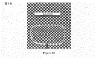
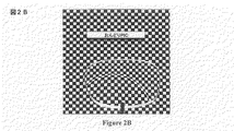
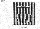
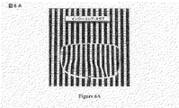
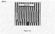
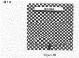
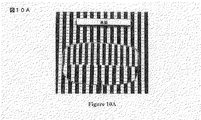
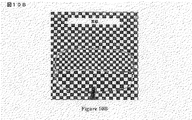
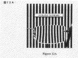
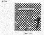
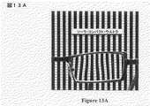
画像乱れ:画像乱れは、レンズを通して眺めるときの画像の知覚混乱である。画像乱れが生じるとき、レンズを通して知覚される画像はもはやシームレスではない。画像乱れは、画像乱れを横切った画像のプリズム変移、画像乱れを横切った画像の倍率変化、画像乱れまたはその周辺の画像の突然の曇り、または三つのある組み合わせがなり得る。レンズが画像乱れを有するかどうかを判断する一つの方法は、鉛直線、水平線またはグリッドのセットの上方の固定距離にレンズを置くことである。図1A〜10Bは、ラップトップ・スクリーンから19.5”で撮影された鉛直線またはグリッドのいずれかを表示しているラップトップ・スクリーンから6”に保持された−1.25D遠距離矯正と+2.25D追加パワーを有している異なるレンズを示す。図1Aと1Bは、本発明の実施形態によるレンズを示す。図2Aと2Bは、本発明の別の実施形態によるレンズを示す。図3Aと3Bは、本発明の別の実施形態によるレンズを示す。図4Aと4Bは、本発明の別の実施形態によるレンズを示す。図5Aと5Bは、フラット・トップ・ポリ・レンズを示す。図6Aと6Bは、スラブ・オフ・プリズムを備えたイージー・トップ・レンズを示す。図7Aと7Bは、イージー・トップ・レンズを示す。図8Aと8Bは、混合二焦点レンズを示す。図9Aと9Bは、フラット・トップ三焦点レンズを示す。図10Aと10Bは、高級レンズを示す。図11Aと11Bは、ラップトップ・スクリーンから19.5”で撮影された鉛直線またはグリッドのいずれかを表示しているラップトップ・スクリーンから6”に保持された−2.25D遠距離矯正と+2.00D追加パワーを有しているソーラ・オプティカル(Sola Optical)によって商標登録されたソーラ・スマートセグ(Sola SmartSeg)(登録商標)レンズを示す。図12A〜13Bは、ラップトップ・スクリーンから19.5”で撮影された鉛直線またはグリッドのいずれかを表示しているラップトップ・スクリーンから6”に保持された−1.25D遠距離矯正と+2.25D追加パワーを有している異なるレンズを示す。図12Aと12Bは、エシロール(Essilor)によって商標登録されたバリラックス・フィジオ360(Varilux Physio 360)(登録商標)レンズを示す。図13Aと13Bは、カール・ツァイス・ビジョン(Carl Zeiss Vision)によって商標登録されたソーラ・コンパクト・ウルトラ(Sola Compact Ultra)(登録商標)レンズを示す。図1A〜11Bに示されるレンズは、知覚画像乱れを産出するレンズである。図12A〜13Bに示されるレンズは、知覚画像乱れを産出しないレンズである。 Image turbulence: Image turbulence is the perceptual disruption of an image when viewed through a lens. When image disturbance occurs, the image perceived through the lens is no longer seamless. Image disturbance can be a prism transition of the image across the image disturbance, a magnification change of the image across the image disturbance, an image disturbance or a sudden cloudiness of the surrounding image, or some combination of the three. One way to determine whether a lens has image disturbance is to place the lens at a fixed distance above a set of vertical, horizontal or grid lines. FIGS. 1A-10B show a -1.25D long range correction held 6 ″ from a laptop screen displaying either a vertical line or a grid taken at 19.5 ″ from the laptop screen. Fig. 4 shows different lenses with + 2.25D additional power. 1A and 1B show a lens according to an embodiment of the present invention. 2A and 2B show a lens according to another embodiment of the present invention. 3A and 3B show a lens according to another embodiment of the present invention. 4A and 4B show a lens according to another embodiment of the present invention. Figures 5A and 5B show a flat top poly lens. 6A and 6B show an easy top lens with a slab off prism. 7A and 7B show an easy top lens. 8A and 8B show a mixed bifocal lens. 9A and 9B show a flat top trifocal lens. 10A and 10B show a high-grade lens. FIGS. 11A and 11B show a -2.25D long-range correction held 6 ″ from a laptop screen displaying either a vertical line or a grid taken at 19.5 ″ from the laptop screen. Fig. 3 shows a Sola SmartSeg (R) lens registered by Sola Optical having + 2.00D additional power. FIGS. 12A-13B show a -1.25D long range correction held 6 ″ from a laptop screen displaying either a vertical line or a grid taken at 19.5 ″ from the laptop screen. Fig. 4 shows different lenses with + 2.25D additional power. Figures 12A and 12B show a Varilux Physio 360 (R) lens registered by Essilor. FIGS. 13A and 13B show a Sola Compact Ultra® lens trademarked by Carl Zeiss Vision. The lenses shown in FIGS. 1A-11B are lenses that produce perceptual image disturbances. The lenses shown in FIGS. 12A to 13B are lenses that do not produce perceptual image disturbance.
増分追加パワー:ユーザーが近距離で明瞭に見えるのに必要とされる総追加パワー未満である追加パワー。増分追加パワーを有している領域は一般的に、ユーザーが近距離で明瞭に見えるのに必要とされる総追加パワー未満である最大追加パワーを有する。おのおのが増分追加パワーを有している二つ以上の領域が互いに光学的連絡して置かれ得る。領域は互いに光学的連絡にあるので、個々の増分追加パワーは、ユーザーが近距離で明瞭に見えるのに必要とされる追加パワーに等しい総複合増分追加パワーを作り出すために付加的であり得る。領域の増分追加パワーは、屈折光学部品または回折光学部品を使用してそれぞれ屈折または回折により生成され得る。ある場合には、領域は、ユーザーが中間距離で明瞭に見えるのに必要とされる総追加パワー未満を有し得る。そのような場合、領域は「増分中間距離追加パワー」有すると言われる。 Incremental additional power: Additional power that is less than the total additional power required for the user to see clearly at close range. Regions with incremental additional power typically have a maximum additional power that is less than the total additional power required for the user to be clearly visible at close range. Two or more regions, each having incremental additional power, can be placed in optical communication with each other. Since the regions are in optical communication with each other, the individual incremental additional power may be additional to create a total composite incremental additional power that is equal to the additional power required for the user to clearly see at close range. The incremental additional power of the region can be generated by refraction or diffraction, respectively, using refractive or diffractive optics. In some cases, the region may have less than the total additional power required for the user to see clearly at intermediate distances. In such a case, the region is said to have “incremental intermediate distance additional power”.
中距離ゾーン:ユーザーが中距離で明瞭に見えることを可能にする光学パワーを包含しているレンズの一部または領域。中距離ゾーンは中間の視力ゾーンとも呼ばれ得る。 Mid-range zone: A part or area of a lens that contains optical power that allows the user to see clearly at medium range. The mid-range zone may also be referred to as the intermediate vision zone.
中距離:ある人が、ただ単に例として、新聞を読むとき、コンピューターで仕事をするとき、流しで皿を洗うとき、または衣類にアイロンをかけるときに眺める距離。この距離は、いつもとは限らないが通常は、目からほぼ16インチとほぼ29インチの間にあると見なされる。中距離は、中視野距離とも中距離ポイントとも呼ばれ得る。「近距離」は目からほぼ10インチからほぼ16インチまでの間にあるので「中距離」は「近中距離」とも呼ばれ得ることは注目されるべきである。あるいは、ほぼ16インチに接近する「中距離」の一部だけが「近中距離」と呼ばれ得る。「遠中距離」は「中距離」と混同してはならない。「遠中距離」は、目からほぼ29インチからほぼ5フィート(または10フィート)までの間ではない。 Medium distance: The distance a person looks at when reading a newspaper, working on a computer, washing dishes in a sink, or ironing clothes, by way of example only. This distance is usually, but not always, considered to be between approximately 16 inches and approximately 29 inches from the eye. The medium distance may be referred to as a medium viewing distance or a medium distance point. It should be noted that “medium distance” can also be referred to as “near distance” since “short distance” is between approximately 10 inches and approximately 16 inches from the eye. Alternatively, only a portion of “medium distance” approaching approximately 16 inches may be referred to as “near-medium distance”. “Distance distance” should not be confused with “medium distance”. The “far-medium distance” is not between approximately 29 inches and approximately 5 feet (or 10 feet) from the eye.
レンズ:光を収束または発散させるデバイスの任意のデバイスまたは部分。レンズは、屈折的または回折的であり得る。レンズは、一方または両方の表面が凸、凹またはプラノであり得る。レンズは、球状、円筒状、プリズム状、またはそれらの組み合わせであり得る。レンズは、光学ガラス、プラスチック、熱可塑性樹脂、熱硬化樹脂、ガラスと樹脂の合成物、または異なる光学的グレード樹脂またはプラスチックの合成物で作られ得る。レンズは、光学素子、光学プレフォーム、光学ウェーハ、完成レンズ・ブランクまたは光学部品と呼ばれ得る。光産業内では、デバイスは、たとえ(プラノまたは光学パワーなしとして知られている)ゼロ光学パワーを有するとしても、レンズと呼ばれ得ることは注目されるべきである。レンズは通常、人がレンズを着用したときに、垂直に方向づけられる。その結果、レンズの遠距離ゾーンがトップにあり、近距離部分がボトムにある。レンズに関して使用される「上部」、「下部」、「上方」、「下方」、「鉛直」、「水平」、「上」、「下」、「左」、「右」、「トップ」、「ボトム」との用語は、この方向づけに対して用いられ得る。 Lens: Any device or part of a device that focuses or diverges light. The lens can be refractive or diffractive. The lens can be convex, concave or plano on one or both surfaces. The lens can be spherical, cylindrical, prismatic, or a combination thereof. The lens can be made of optical glass, plastic, thermoplastic resin, thermoset resin, glass and resin composite, or different optical grade resin or plastic composite. The lens may be referred to as an optical element, optical preform, optical wafer, finished lens blank, or optical component. It should be noted that within the optical industry, a device can be referred to as a lens even if it has zero optical power (known as plano or no optical power). The lens is usually oriented vertically when a person wears the lens. As a result, the far-field zone of the lens is at the top and the near-field portion is at the bottom. “Upper”, “Lower”, “Upper”, “Lower”, “Vertical”, “Horizontal”, “Upper”, “Lower”, “Left”, “Right”, “Top”, “ The term “bottom” may be used for this orientation.
レンズ・ブランク:レンズに形づくられ得る光学材料で作られていたデバイス。レンズ・ブランクは、その外側表面の両方が屈折性外側表面に形づくられたことを意味して「完成」され得る。完成レンズ・ブランクは、ゼロまたはプラノ光学パワーを含んでいる任意の光学パワーであり得る光学パワーを有する。レンズ・ブランクは「半完成」レンズ・ブランクであり得、レンズ・ブランクが一つの完成屈折性外側表面だけを有するように形づくられたことを意味している。レンズ・ブランクは「未完成」レンズ・ブランクであり得、レンズ・ブランクの外側表面のいずれもが屈折性表面に形づくられていないことを意味している。未完成または半完成レンズ・ブランクの未完成表面は、フリー形成として知られている製造プロセスによって、またはより伝統的な表面仕上げおよび研磨によって完成され得る。完成レンズ・ブランクは、眼鏡フレームに適合するように、その周辺エッジが形作られていないか、エッジ加工されていないか、修正されていない。この定義のため、完成レンズ・ブランクはレンズである。しかしながら、レンズ・ブランクは、ひとたび眼鏡フレームに適合するように形づくられるかエッジ加工されるか修正されれば、もはやレンズ・ブランクと呼ばれない。 Lens blank: A device made of an optical material that can be shaped into a lens. A lens blank can be “finished” meaning that both of its outer surfaces have been shaped into a refractive outer surface. The finished lens blank has an optical power that can be zero or any optical power including plano optical power. The lens blank can be a “semi-finished” lens blank, meaning that the lens blank has been shaped to have only one finished refractive outer surface. The lens blank may be an “incomplete” lens blank, meaning that none of the outer surfaces of the lens blank are shaped into a refractive surface. The unfinished surface of an unfinished or semi-finished lens blank can be completed by a manufacturing process known as free forming, or by more traditional surface finishing and polishing. The finished lens blank is not shaped, edged or modified at its peripheral edges to fit the spectacle frame. For this definition, the finished lens blank is a lens. However, a lens blank is no longer referred to as a lens blank once it has been shaped or edged or modified to fit a spectacle frame.
ラインド多焦点レンズ:レンズの着用者を眺める誰かに気づかれ得る可視不連続部を有している異なる光学パワーの二つ以上の隣接領域を有する多焦点レンズ。不連続部は、二つ以上の領域間に知覚画像乱れを引き起こす。ラインド(lined)多焦点レンズの例は、ラインド(lined)(混合されていない)二焦点または三焦点である。 Lined Multifocal Lens: A multifocal lens that has two or more adjacent regions of different optical power with visible discontinuities that can be noticed by someone looking at the lens wearer. The discontinuity causes a perceptual image disturbance between two or more regions. An example of a lined multifocal lens is a lined (unmixed) bifocal or trifocal.
ラインレス多焦点レンズ:累進追加レンズ中などの二つ以上の領域間に不連続部を有していないか、レンズの着用者を眺める誰かに気づかれ得ない二つ以上の領域の間に不可視不連続部を有している異なる光学パワーの二つ以上の隣接領域を有する多焦点レンズ。不連続部は、二つ以上の領域間に知覚画像乱れを引き起こす。不連続部を有しているラインレス多焦点レンズの一例は混合二焦点である。PALはラインレス多焦点と呼ばれ得るが、PALは不連続部を有しない。 Lineless multifocal lens: Does not have a discontinuity between two or more areas, such as in a progressive addition lens, or is invisible between two or more areas that cannot be noticed by someone looking at the lens wearer A multifocal lens having two or more adjacent regions of different optical power having discontinuities. The discontinuity causes a perceptual image disturbance between two or more regions. An example of a lineless multifocal lens having a discontinuity is mixed bifocal. Although PAL can be referred to as lineless multifocal, PAL has no discontinuities.
低追加パワーPAL:着用者が近視野距離で明瞭に見えるための必要近追加パワーよりも少ないを有する累進追加レンズ(すなわち、それは増分追加パワーを有する)。 Low additional power PAL: A progressive additional lens that has less than the required near additional power for the wearer to see clearly at near field distance (ie, it has incremental additional power).
低追加パワー累進光学パワー領域:着用者が近視野距離で明瞭に見えるための必要近追加パワーよりも少ないを有する累進光学パワー領域(すなわち、それは増分追加パワーを有する)。 Low additional power progressive optical power region: A progressive optical power region having less than the near additional power necessary for the wearer to clearly see at near field distance (ie, it has incremental additional power).
多焦点レンズ:一つを超える焦点または光学パワーを有しているレンズ。そのようなレンズは静的または動的であり得る。静的多焦点レンズの例としては、二焦点レンズ、三焦点レンズまたは累進追加レンズがあげられる。動的多焦点レンズは、ただ単に例として、電気活性レンズを含む。さまざまな光学パワーが、使用される電極のタイプ、電極に印加される電圧、および液晶の薄層内に変更される屈折率に依存して、電気活性レンズ中に作り出され得る。動的多焦点レンズはまた、ただ単に例として、気体レンズおよび流体レンズなどの従順な光学的部材を備えているレンズ、二つ以上の可動部が光学パワーを調節する機械的調整可能レンズ、または電気的メニスクスレンズを含む。多焦点レンズはまた、静的および動的の組み合わせであり得る。たとえば、静的球面レンズ、静的単一視力レンズ、ただ単に例として、累進追加レンズ、フラット・トップ28二焦点、またはフラット・トップ7×28三焦点などの静的多焦点レンズに光学的連絡して電気活性素子が使用され得る。すべてではないがほとんどの場合、多焦点レンズは屈折レンズである。ある場合には、多焦点レンズは、回折光学素子および/または回折および屈折光学部品の組み合わせを備え得る。 Multifocal lens: A lens that has more than one focal point or optical power. Such lenses can be static or dynamic. Examples of static multifocal lenses include bifocal lenses, trifocal lenses, or progressive addition lenses. A dynamic multifocal lens includes, by way of example only, an electroactive lens. Various optical powers can be created in the electroactive lens, depending on the type of electrode used, the voltage applied to the electrode, and the refractive index that is changed in the thin layer of liquid crystal. A dynamic multifocal lens is also a lens with compliant optical members, such as a gas lens and a fluid lens, merely as an example, a mechanically adjustable lens in which two or more moving parts adjust optical power, or Includes electrical meniscus lenses. Multifocal lenses can also be a combination of static and dynamic. For example, static contact lenses such as static spherical lenses, static single vision lenses, progressive addition lenses, flat top 28 bifocals, or flat top 7 × 28 trifocals, merely by way of example. Electroactive elements can then be used. In most, if not all, multifocal lenses are refractive lenses. In some cases, the multifocal lens may comprise a combination of diffractive optical elements and / or diffractive and refractive optical components.
近距離ゾーン:ユーザーが近距離で明瞭に見えることを可能にする光学パワーを包含しているレンズの一部または領域。近距離ゾーンは近方視力ゾーンとも呼ばれ得る。 Near range zone: A part or area of a lens that contains optical power that allows the user to see clearly at close range. The short distance zone may also be referred to as the near vision zone.
近距離:ある人が、ただ単に例として、本を読むとき、針に糸を通すとき、または錠剤ボトルの指示を読むときに眺める距離。この距離は、いつもとは限らないが通常は、目からほぼ10インチとほぼ16インチの間にあると見なされる。近距離は、近視野距離とも近距離ポイントとも呼ばれ得る。 Short distance: The distance a person looks at when reading a book, threading a needle, or reading instructions on a pill bottle, by way of example only. This distance is usually but not always considered to be between approximately 10 inches and approximately 16 inches from the eye. The short distance can be referred to as a near field distance or a short distance point.
オフィス・レンズ/オフィスPAL:遠距離視力ゾーンを大概中距離視力ゾーンのそれで取り替え、近距離ゾーンに近距離視力を中距離ゾーンに中距離視力を一般に提供する特別設計職業的累進追加レンズ。光学パワーは、近距離ゾーンから中距離ゾーンまで下降する。総光学パワー下降は、着用者の一般的近距離追加パワーよりも少ない光学パワー変化である。その結果、より広いチャンネル幅とまたより広い読取幅によってより広い中距離視力が提供される。これは、より大きい値の不所望な非点収差をフィッティング・クロスの上方に一般的に許す光学設計によって成し遂げられる。これらの特徴のため、この種のPALはデスク・ワークに好適であるが、レンズは遠距離視野エリアをたとえあるとしてもほとんど包含していないので、ある人が彼または彼女の自動車を運転したり、オフィスまたは家の周りを歩くために使用したりし得ない。 Office Lens / Office PAL: A specially designed professional progressive addition lens that replaces the long-distance vision zone with that of the medium-distance vision zone, generally providing short-distance vision for the short-distance zone and generally medium-distance vision for the mid-range zone. The optical power falls from the short distance zone to the middle distance zone. The total optical power drop is a change in optical power that is less than the wearer's general short range additional power. As a result, a wider mid-range vision is provided by a wider channel width and also a wider reading width. This is accomplished by an optical design that generally allows larger values of unwanted astigmatism above the fitting cross. Because of these features, this type of PAL is suitable for desk work, but the lens contains little, if any, far field area, so a person can drive his or her car Can not be used to walk around the office or home.
眼用レンズ:ただ単に例として、眼鏡レンズ、コンタクトレンズ、眼内レンズ、角膜インレーおよび角膜オンレーを含む視力矯正に適したレンズ。 Ophthalmic lenses: lenses suitable for vision correction, including, by way of example only, spectacle lenses, contact lenses, intraocular lenses, corneal inlays and corneal onlays.
光学的連絡:二つ以上の光学パワー領域が整列され、光が整列領域を通過し、光が通過する点における各個々領域の光学パワーの和に等しい複合光学パワーを経験する状態。領域は、レンズ内に、または同じレンズまたは異なるレンズの反対表面上に埋設され得る。 Optical communication: A condition in which two or more optical power regions are aligned, light passes through the alignment region, and experiences a composite optical power equal to the sum of the optical power of each individual region at the point where the light passes. The region may be embedded in the lens or on the opposite surface of the same lens or a different lens.
光学パワー領域:光学パワーを有しているレンズの領域。 Optical power area: An area of a lens having optical power.
光学パワーの平坦域:領域またはゾーンの水平幅および/または鉛直長さを横切って大概一定光学パワーを有するレンズの領域またはゾーン。あるいは、光学パワー変化は、領域またはゾーンの水平幅および/または鉛直長さを横切った1ミリメートルあたりほぼ0.05D以下の平均であり得る。別の代替案としては、光学パワー変化は、領域またはゾーンの水平幅および/または鉛直長さを横切った1ミリメートルあたりほぼ0.10D以下の平均であり得る。最終の代替案としては、光学パワー変化は、領域またはゾーンの水平幅および/または鉛直長さを横切った1ミリメートルあたりほぼ0.20D以下の平均であり得る。領域またはゾーンは、ほぼ1mm以上の水平幅および/または鉛直長さを有し得る。代替案としては、領域またはゾーンは、ほぼ1mmないしほぼ3mm以上の水平幅および/または鉛直長さを有し得る。最終の代替案としては、領域またはゾーンは、ほぼ2mmないしほぼ6mm以上の水平幅および/または鉛直長さを有し得る。光学パワーの平坦域は、領域内の光学パワーの鉛直安定性および/または光学パワーの水平安定性を与える。光学パワーの平坦域はレンズの着用者によって、彼または彼女のあごを上下に動かすことによって、または左右を眺めることによって視覚的に認識されるだろう。領域が光学パワーの平坦域を有するならば、着用者は、与えられた距離にある物体が領域の至る所で大概合焦したままでいることに気づくであろう。領域またはゾーンは、遠距離ゾーン、上部遠中距離ゾーン、中距離ゾーン、近距離ゾーン、下部遠中距離ゾーンまたはレンズの任意の他の領域であり得る。 Optical power plateau: A region or zone of a lens having a generally constant optical power across the horizontal width and / or vertical length of the region or zone. Alternatively, the optical power change may be an average of approximately 0.05 D or less per millimeter across the horizontal width and / or vertical length of the region or zone. As another alternative, the optical power change may be an average of approximately 0.10 D or less per millimeter across the horizontal and / or vertical length of the region or zone. As a final alternative, the optical power change may be an average of approximately 0.20 D or less per millimeter across the horizontal width and / or vertical length of the region or zone. The region or zone may have a horizontal width and / or a vertical length of approximately 1 mm or more. Alternatively, the region or zone may have a horizontal width and / or vertical length of approximately 1 mm to approximately 3 mm or more. As a final alternative, the region or zone may have a horizontal width and / or vertical length of approximately 2 mm to approximately 6 mm or more. The optical power plateau provides vertical stability and / or horizontal stability of the optical power within the region. The optical power plateau will be visually perceived by the wearer of the lens, by moving his or her chin up or down, or looking left and right. If the region has a plateau of optical power, the wearer will notice that an object at a given distance remains largely in focus throughout the region. The region or zone can be a far zone, an upper far middle zone, a middle zone, a near zone, a lower far middle zone or any other region of the lens.
累進追加領域:PALの遠距離ゾーンとPALの近距離ゾーンの間の連続的増大光学パワーを与えるPALの連続的領域。領域の始まりでの遠距離ゾーンの追加パワーは、ほぼ+0.10D以下である。ある場合には、領域は、レンズの近距離ゾーンで全追加パワーに到達した後、減少光学パワーを与え得る。 Progressive additional region: A continuous region of PAL that provides continuously increasing optical power between the far zone of PAL and the near zone of PAL. The additional power of the far zone at the beginning of the region is approximately +0.10 D or less. In some cases, the region may provide reduced optical power after reaching full additional power in the lens's near zone.
累進追加表面:PALの遠距離ゾーンとPALの近距離ゾーンの間の連続的増大光学パワーを与えるPALの連続的表面。表面の始まりでの遠距離ゾーンでの追加パワーは、ほぼ+0.10D以下である。ある場合には、表面は、全追加パワーがレンズの近距離ゾーンで到達した後、減少光学パワーを与え得る。 Progressive additional surface: A continuous surface of PAL that provides continuously increasing optical power between the far zone of PAL and the near zone of PAL. The additional power in the far zone at the beginning of the surface is approximately +0.10 D or less. In some cases, the surface may provide reduced optical power after the total additional power has reached in the lens's near zone.
累進光学パワー領域:一般に領域の上部部分に第一光学パワーを、また一般に領域の下部部分に第二光学パワーを有しており、それらの間に光学パワーの連続的変化が存在するレンズの領域。累進光学パワー領域は、レンズの表面上にあり得るか、レンズ内に埋設され得る。累進光学パワー領域は、「累進光学パワー表面」として知られる一つ以上の表面トポグラフィを備え得る。累進光学パワー表面は、レンズの一方の表面上にあり得るか、レンズ内に埋め込まれ得る。累進光学パワー領域は、光学パワーが隣接視力ゾーンの光学パワーを超えて増大されるとき、「始まる」または「始める」と言われる。一般に、この増大は、+0.12D以上のプラスの光学パワーである。累進光学パワー領域の始まりでの増大プラス光学パワーは、正の光学パワーの大概連続的増大によって引き起こされ得る。あるいは、累進光学パワー領域の始まりでの追加パワーは、累進光学パワー領域の一部または異なる光学パワー領域の一部のいずれかである光学パワーのステップによって引き起こされ得る。光学パワーのステップは、不連続部によって引き起こされ得る。累進光学パワー領域の光学パワーは、その最大追加パワーに到達した後に減少し得る。累進光学パワー領域は、従来の累進追加レンズのようにフィッティング・ポイントまたはその近くから始まり得るか、本発明の実施形態のようにフィッティング・ポイントの下方から始まり得る。 Progressive optical power region: a region of a lens that generally has a first optical power in the upper part of the region and a second optical power in the lower part of the region, where there is a continuous change in optical power between them. . The progressive optical power region can be on the surface of the lens or can be embedded in the lens. The progressive optical power region may comprise one or more surface topographies known as “progressive optical power surfaces”. The progressive optical power surface can be on one surface of the lens or embedded in the lens. The progressive optical power region is said to “begin” or “begin” when the optical power is increased beyond the optical power of the adjacent vision zone. In general, this increase is a positive optical power of + 0.12D or more. The increase at the beginning of the progressive optical power region plus optical power can be caused by an almost continuous increase in positive optical power. Alternatively, the additional power at the beginning of the progressive optical power region can be caused by an optical power step that is either part of the progressive optical power region or part of a different optical power region. The optical power step can be caused by a discontinuity. The optical power in the progressive optical power region can decrease after reaching its maximum additional power. The progressive optical power region can begin at or near the fitting point as in a conventional progressive addition lens, or it can begin from below the fitting point as in embodiments of the present invention.
読取幅:明瞭で大概ひずみのない矯正を0.25Dの着用者の近距離視野光学パワー矯正内の光学パワーで提供するレンズの近距離視野部内の最狭水平幅。 Read Width: The narrowest horizontal width in the near field of the lens that provides clear, mostly distortion free correction with optical power within the 0.25D wearer's near field optical power correction.
短いチャンネル長:アイウェア流行の美的な関係または傾向のために、狭い鉛直高さを有するフレーム・スタイル内へ適合するために鉛直に縮小されたレンズを有することが望まれ得る。そのようなレンズでは、チャンネルもまた当然より短い。短いチャンネル長は、縮小レンズ中のチャンネルの長さを指す。これらのチャンネル長は、いつもとは限らないが通常は、ほぼ9mmとほぼ13mmの間にある。一般には、より短いチャンネル長は、より狭いチャンネル幅とより多い不所望な非点収差を意味する。より短い鉛直チャンネル長によって引き起こされる光学パワーのより急峻な増大のために遠距離矯正と近距離矯正の間の推移がより難しいので、より短いチャンネル設計は時に、「ハード」累進追加レンズ設計と関連してある特性を有しているように言及される。 Short channel length: Due to aesthetic relationships or trends in eyewear fashion, it may be desirable to have a vertically reduced lens to fit within a frame style with a narrow vertical height. In such lenses, the channel is of course also shorter. A short channel length refers to the length of the channel in the reduction lens. These channel lengths are usually, but not always, between approximately 9 mm and approximately 13 mm. In general, a shorter channel length means a narrower channel width and more unwanted astigmatism. Shorter channel designs are sometimes associated with “hard” progressive addition lens designs because the transition between long and short range corrections is more difficult due to the steeper increase in optical power caused by shorter vertical channel lengths Are referred to as having certain characteristics.
ソフト累進追加レンズ:遠距離矯正と近距離矯正の間により大きい漸進的推移を備えた累進追加レンズ。このより大きい漸進的推移は、不所望な非点収差の増量を引き起こす。ソフトPALでは、不所望な非点収差の増量は、レンズを横切って延びるフィッティング・ポイントを通って配置された仮想水平線上に侵入し得る。ソフトPALはまた、より長いチャンネル長とより広いチャンネル幅を有し得る。「修正ソフト累進追加レンズ」は、より急峻な光学パワー推移、より短いチャンネル、より狭いチャンネル、レンズの視野部分に押し込まれたより多い不所望な非点収差、およびフィッティング・ポイントの下方のより多い不所望な非点収差など、ハードPALの一つ以上の特性を有している修正光学設計を有するソフトPALである。 Soft progressive addition lens: A progressive addition lens with a greater gradual transition between long-range and short-range correction. This larger gradual transition causes an undesirable increase in astigmatism. In soft PAL, an undesirable increase in astigmatism can penetrate onto a virtual horizon located through a fitting point that extends across the lens. Soft PAL may also have longer channel lengths and wider channel widths. The “corrected soft progressive addition lens” has a steeper optical power transition, shorter channels, narrower channels, more unwanted astigmatism pushed into the field of view of the lens, and more misalignment below the fitting point. A soft PAL having a modified optical design that has one or more characteristics of a hard PAL, such as desired astigmatism.
静的レンズ:電気エネルギー、力学的エネルギーまたは力の印加で変更可能でない光学パワーを有しているレンズ。静的レンズの例としては、球面レンズ、シリンドリカルレンズ、累進追加レンズ、二焦点および三焦点があげられる。静的レンズは、固定レンズとも呼ばれ得る。 Static lens: A lens having optical power that cannot be changed by the application of electrical energy, mechanical energy or force. Examples of static lenses include spherical lenses, cylindrical lenses, progressive addition lenses, bifocal and trifocal. Static lenses can also be referred to as fixed lenses.
光学パワーのステップ:光学パワー不連続部になり得る二つの光学ゾーンまたは領域の間の光学パワー差。光学パワー差は、レンズの上部部分と下部部分の間で光学パワーが増大する光学パワーのステップ増であり得る。光学パワー差は、レンズの上部部分と下部部分の間で光学パワーが減少する光学パワーのステップ減であり得る。たとえば、レンズの上部部分が+1.00Dの光学パワーを有するならば、+0.50Dの光学パワーの「ステップ増」は、+1.50Dの光学パワーを有している光学パワーのステップ増(または不連続部)の直後にレンズの下部部分になるであろう。下部領域の光学パワーは、光学パワーのステップによって「作り出される」と言われる。 Optical power step: The optical power difference between two optical zones or regions that can be optical power discontinuities. The optical power difference may be a step increase in optical power where the optical power increases between the upper and lower portions of the lens. The optical power difference can be a step reduction in optical power where the optical power decreases between the upper and lower portions of the lens. For example, if the upper part of the lens has an optical power of + 1.00D, an “step increase” of + 0.50D optical power is a step increase (or non-increase) of optical power having an optical power of + 1.50D. It will be the lower part of the lens immediately after the continuous part). The optical power in the lower region is said to be “created” by the optical power step.
不所望な非点収差:患者の処方視力矯正の一部でないが、どちらかといえば二つの光学パワー・ゾーンを接合する光学パワーの滑らかな勾配のためにレンズの光学設計の副産物であるレンズ内に見つかる不所望な非点収差。レンズは、さまざまな屈折パワーのレンズの異なるエリアを横切って変化する不所望な非点収差を有し得るが、用語「不所望な非点収差」は一般に、レンズ内に見つかる最大の不所望な非点収差を指す。不所望な非点収差はまた、全体としてのレンズとは対称的にレンズの特定部内に配置された不所望な非点収差としてさらに特徴づけされ得る。そのような場合、限定的言語は、レンズの特定部内の不所望な非点収差だけが考慮されていることを示すために使用される。レンズの着用者は、不所望な非点収差を、レンズによって引き起こされる曇りおよび/またはひずみととらえる。レンズの不所望な非点収差とひずみがほぼ1.00D以下である限り、レンズのユーザーは、ほとんどの場合、それにほとんど気づかないと、光産業内では知られ受け入れられている。 Undesirable astigmatism: in the lens that is not part of the patient's prescription vision correction, but rather is a byproduct of the lens's optical design due to the smooth gradient of optical power that joins the two optical power zones Undesirable astigmatism found in. Although the lens may have unwanted astigmatism that varies across different areas of the lens of varying refractive power, the term “undesired astigmatism” is generally the largest unwanted astigmatism found in the lens. Refers to astigmatism. Undesirable astigmatism can also be further characterized as undesired astigmatism located within a particular portion of the lens symmetrically with the lens as a whole. In such a case, a limited language is used to indicate that only unwanted astigmatism within a particular part of the lens is considered. Lens wearers view unwanted astigmatism as haze and / or distortion caused by the lens. As long as the unwanted astigmatism and distortion of the lens is less than or equal to approximately 1.00 D, lens users are known and accepted within the optical industry, most often not being aware of it.
光学パワーの鉛直安定性:領域またはゾーンの鉛直長さを横切って大概一定光学パワーを有するレンズの領域またはゾーン。あるいは、光学パワー変化は、領域またはゾーンの鉛直長さを横切った1ミリメートルあたりほぼ0.05D以下の平均であり得る。別の代替案としては、光学パワー変化は、領域またはゾーンの鉛直長さを横切った1ミリメートルあたりほぼ0.10D以下の平均であり得る。最終の代替案としては、光学パワー変化は、領域またはゾーンの鉛直長さを横切った1ミリメートルあたりほぼ0.20D以下の平均であり得る。領域またはゾーンは、ほぼ1mm以上の鉛直長さを有し得る。代替案としては、領域またはゾーンは、ほぼ1mmないしほぼ3mm以上の鉛直長さを有し得る。最終の代替案としては、領域またはゾーンは、ほぼ2mmないしほぼ6mm以上の鉛直長さを有し得る。領域またはゾーンは、遠距離ゾーン、上部遠中距離ゾーン、中距離ゾーン、近距離ゾーン、下部遠中距離ゾーンまたはレンズの任意の他の領域であり得る。 Optical power vertical stability: A region or zone of a lens that has a generally constant optical power across the vertical length of the region or zone. Alternatively, the optical power change can be an average of approximately 0.05 D or less per millimeter across the vertical length of the region or zone. As another alternative, the optical power change may be an average of approximately 0.10 D or less per millimeter across the vertical length of the region or zone. As a final alternative, the optical power change may be an average of approximately 0.20 D or less per millimeter across the vertical length of the region or zone. The region or zone may have a vertical length of approximately 1 mm or more. As an alternative, the region or zone may have a vertical length of approximately 1 mm to approximately 3 mm or more. As a final alternative, the region or zone may have a vertical length of approximately 2 mm to approximately 6 mm or more. The region or zone can be a far zone, an upper far middle zone, a middle zone, a near zone, a lower far middle zone or any other region of the lens.
視力の鉛直安定性:ユーザーが領域またはゾーンを横切って上下を眺めるときに領域またはゾーンが大概一定明瞭視力を有するならば、レンズの領域またはゾーンは視力の鉛直安定性を有すると言われる。しかしながら、PALが遠距離ゾーンから近距離ゾーンまで明瞭視力を有する間、これらのゾーン間の光学パワーは混合されることは注目されるべきである。したがって、PALは、遠距離と近距離ゾーンの間の視力の混合安定性を有する。したがって、PALは、遠距離ゾーンと近距離ゾーンの間の光学パワーの非常に限定された鉛直安定性を有する。領域またはゾーンは、ほぼ1mm以上の鉛直長さを有し得る。代替案としては、領域またはゾーンは、ほぼ1mmないしほぼ3mm以上の鉛直長さを有し得る。最終の代替案としては、領域またはゾーンは、ほぼ2mmないしほぼ6mm以上の鉛直長さを有し得る。領域またはゾーンは、遠距離ゾーン、上部遠中距離ゾーン、中距離ゾーン、近距離ゾーン、下部遠中距離ゾーンまたはレンズの任意の他の領域であり得る。 Vertical stability of visual acuity: A lens region or zone is said to have vertical stability of vision if the region or zone has a generally constant clear visual acuity when the user looks up and down across the region or zone. However, it should be noted that while the PAL has clear vision from the far zone to the near zone, the optical power between these zones is mixed. Thus, PAL has a visual stability mixing stability between long and short distance zones. Thus, PAL has a very limited vertical stability of optical power between the long and short zones. The region or zone may have a vertical length of approximately 1 mm or more. As an alternative, the region or zone may have a vertical length of approximately 1 mm to approximately 3 mm or more. As a final alternative, the region or zone may have a vertical length of approximately 2 mm to approximately 6 mm or more. The region or zone can be a far zone, an upper far middle zone, a middle zone, a near zone, a lower far middle zone or any other region of the lens.
本発明の実施形態は、PALsに関連するほとんどでないにしても多くの問題を解決し得る光学設計、レンズおよびアイウェア・システムに関する。さらに、実施形態は、PALsに関連するほとんどの視力妥協を除去し得る。実施形態は、さまざまな距離について大概連続的合焦能力を提供しながら、着用者にとって適切な遠距離、中距離および近距離光学パワーを達成する手段を提供し得る。実施形態はまた、大概連続的合焦能力を提供しながら、着用者にとって適切な上部遠中距離および/または下部遠中距離光学パワーを達成する手段を提供し得る。実施形態は、PALよりもはるかに少ない不所望な非点収差を有する。実施形態は、+0.12Dステップまたは+0.25Dステップのいずれかで+1.00Dから+3.50Dまでの追加パワーで全領域の老眼矯正を与え得る。+3.00Dを下回る追加パワー処方については、実施形態は、不所望な非点収差を最大限ほぼ最大限1.00D以下に一般に維持する。+3.00D、+3.25Dおよび+3.50Dなどのある高い追加パワー処方については、実施形態は、不所望な非点収差を最大限ほぼ1.50Dに一般に維持する。 Embodiments of the present invention relate to optical designs, lenses and eyewear systems that can solve many, if not most, problems associated with PALs. Furthermore, embodiments may eliminate most vision compromises associated with PALs. Embodiments may provide a means to achieve appropriate long, medium and short range optical power for the wearer while providing generally continuous focusing capability for various distances. Embodiments may also provide a means to achieve upper far-medium distance and / or lower far-medium optical power appropriate for the wearer while providing mostly continuous focusing capability. Embodiments have much less unwanted astigmatism than PAL. Embodiments may provide full area presbyopia correction with additional power from + 1.00D to + 3.50D in either a + 0.12D step or a + 0.25D step. For additional power prescriptions below + 3.00D, embodiments generally maintain undesired astigmatism at most approximately maximally 1.00D or less. For certain high additional power prescriptions such as + 3.00D, + 3.25D, and + 3.50D, embodiments generally maintain undesired astigmatism at a maximum of approximately 1.50D.
本発明の実施形態は、二つの別々の光学素子を一つの多焦点レンズに光学的に組み合わせることを与え得る。第一光学素子は、大概球状光学パワーを与える大概球状パワー領域を有し得る。大概球状光学パワーは、屈折光学部品または回折光学部品によってそれぞれ屈折または回折により生成され得る。第二光学素子は、累進光学パワーを与える累進光学パワー領域を有し得る。累進光学パワーを与える第二光学素子は、ユーザーが近距離で明瞭に見えるのに十分な追加パワーを提供しない(すなわち、第二光学素子は増分追加パワーを有する)。第一光学素子は、ユーザーが近距離で明瞭に見えることを可能にするために第二光学素子によって提供される光学パワーに加えて光学パワーを提供する大概球状光学パワーを与え得る(すなわち、第一光学素子は、第二光学素子の増分追加パワーと組み合わされたときに総計でユーザーの近距離追加パワーになる増分追加パワーを有する)。大概球状光学パワーを与える第一光学素子によって総追加パワーの一部が提供されるので、多焦点レンズは、同じ総追加パワーを有しているPALよりも少ない不所望な非点収差を有し得る。 Embodiments of the present invention may provide for optically combining two separate optical elements into a single multifocal lens. The first optical element may have a generally spherical power region that provides a generally spherical optical power. Generally spherical optical power can be generated by refraction or diffraction by refractive or diffractive optics, respectively. The second optical element may have a progressive optical power region that provides progressive optical power. The second optical element that provides progressive optical power does not provide sufficient additional power for the user to clearly see at close range (ie, the second optical element has incremental additional power). The first optical element may provide a generally spherical optical power that provides optical power in addition to the optical power provided by the second optical element to allow the user to see clearly at close range (ie, the first optical element). One optical element has an incremental additional power that, when combined with the incremental additional power of the second optical element, totals the user's near field additional power). A multifocal lens has less unwanted astigmatism than a PAL with the same total additional power, since a portion of the total additional power is provided by the first optical element that provides a generally spherical optical power. obtain.
本発明の実施形態では、第一光学素子は、レンズの周囲物質とは異なる屈折率を有している埋め込み回折光学部品であり得る。別の実施形態では、第一光学素子は、レンズの周囲物質とは異なる屈折率を有している埋め込み回折光学部品であり得る。別の実施形態では、第一光学素子は埋め込み電気活性素子であり得る。別の実施形態では、第一光学素子はレンズの一方または両方の表面上にあり得、たとえば、レンズの外側表面を研削、モールド成形、表面鋳造、絞り加工またはフリー形成することによって提供され得る。 In embodiments of the present invention, the first optical element may be an embedded diffractive optical component having a different refractive index than the lens surrounding material. In another embodiment, the first optical element may be an embedded diffractive optic having a refractive index that is different from the surrounding material of the lens. In another embodiment, the first optical element can be an embedded electroactive element. In another embodiment, the first optical element may be on one or both surfaces of the lens and may be provided, for example, by grinding, molding, surface casting, drawing or free forming the outer surface of the lens.
本発明の実施形態では、第二光学素子は、レンズの一方または両方の表面上にあり得、たとえば、レンズの外側表面を研削、モールド成形、表面鋳造、絞り加工またはフリー形成するによって提供され得る。別の実施形態では、第二光学素子は、レンズ内に埋め込まれ、レンズの周囲物質と異なる屈折率の勾配を有し得る。いつもとは限らないが一般には、光学素子の一つがレンズ内に埋め込まれるならば、他の光学素子はレンズの一方または両方の外側表面上に配置される。 In embodiments of the invention, the second optical element can be on one or both surfaces of the lens, for example provided by grinding, molding, surface casting, drawing or free forming the outer surface of the lens. . In another embodiment, the second optical element may be embedded in the lens and have a refractive index gradient that is different from the surrounding material of the lens. In general, but not always, if one of the optical elements is embedded in the lens, the other optical element is placed on one or both outer surfaces of the lens.
本発明の実施形態では、大概球状光学パワーを与える第一光学素子は、累進光学パワーを与える第二光学素子の少なくとも一部と光学的連絡にある。別の実施形態では、大概球状光学パワーを与える第一光学素子と累進光学パワーを与える第二光学素子は、レンズの外屈折表面上またはレンズ内に埋め込まれ得る単一の光学素子に数学的に組み合わされる。 In embodiments of the present invention, the first optical element that provides generally spherical optical power is in optical communication with at least a portion of the second optical element that provides progressive optical power. In another embodiment, the first optical element that provides generally spherical optical power and the second optical element that provides progressive optical power are mathematically combined into a single optical element that can be embedded on or within the outer refractive surface of the lens. Combined.
本発明の実施形態は、大概球状光学パワー与える第一光学素子と累進光学パワーを与える第二光学素子の適切なアラインメントと位置決めを提供する。本発明の実施形態はまた、大概球状パワー領域によって提供される光学パワーの量、累進光学パワー領域によって提供される光学パワーの量および累進光学パワー領域の光学設計を提供する。本発明の実施形態はまた、大概球状パワー領域のサイズと形および累進光学パワー領域のサイズと形を提供する。これらの設計パラメータの組み合わせは、今日商業的に入手可能な現状PALsと比較して、より広いチャンネル幅とより短いチャンネル長の両方のほかに、少ない不所望な非点収差とひずみを有するはるかに優れた光学設計を与える。 Embodiments of the present invention provide proper alignment and positioning of a first optical element that provides generally spherical optical power and a second optical element that provides progressive optical power. Embodiments of the present invention also provide the amount of optical power provided by the generally spherical power region, the amount of optical power provided by the progressive optical power region, and the optical design of the progressive optical power region. Embodiments of the present invention also provide generally spherical power region size and shape and progressive optical power region size and shape. The combination of these design parameters is much less with both unwanted channel astigmatism and distortion, in addition to both wider channel width and shorter channel length, compared to the current commercially available PALs. Gives an excellent optical design.
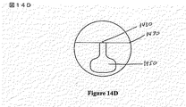
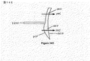
図および図中に示された任意の特徴は実寸どおりに描かれていないことは注目されるべきである。図14Aは、本発明の実施形態によるレンズの前部表面の図を示す。図14Bは、本発明の異なる実施形態の前部表面の図を示す。図14A〜14Bは、レンズの前部凸表面が二つの光学パワー領域を有することを示す。第一光学パワー領域は、レンズの上部部分中の遠距離ゾーン1410である。第二光学パワー領域は、追加的光学パワーを与えるレンズの下部部分中の大概球状パワー領域1420である。追加的光学パワーは増分追加パワーであり得る。図14Aでは、大概球状パワー領域は、レンズのアーチ形セクションの形にある。アーチ形セクションは、レンズの直径よりもはるかに大きい直径を有している円領域と考えられ得る。円領域はレンズには大きすぎるので、その周囲のトップ・アーチだけがレンズ内に適合する。図14Bでは、大概球状パワー領域は円形である。大概球状パワー領域はフィッティング・ポイント1430の下方に配置される。あるいは、大概球状パワー領域は、フィッティング・ポイントまたはその上方に配置され得る。光学パワーの不連続部は、遠距離ゾーンと大概球状パワー領域の間に存在する。不連続部の少なくとも一部は、二つの光学パワー領域間に配置される混合ゾーン1440によって混合され得る。混合ゾーンは、ほぼ2.0mm幅以下またはほぼ0.5mm幅以下であり得る。図14Cは、本発明の実施形態による図14Aまたは図14Bのいずれかのレンズの後部表面の図を示す。図14Cは、レンズの後部凹表面が、追加的光学パワーを与える累進光学パワー領域1450を有することを示す。追加的光学パワーは増分追加パワーであり得る。累進光学パワー領域がレンズの後部凹表面にすべてではないがほとんどの場合に認められるとき、後部凹表面はまた患者の乱視屈折障害を矯正する円環カーブを備えていることは注目されるべきである。累進光学パワー領域はレンズのフィッティング・ポイントの下方から始まる。あるいは、図14Dは、累進光学パワー領域がレンズのフィッティング・ポイントまたはその近くから始まる本発明の実施形態による図14Aまたは図14Bのいずれかのレンズの後部表面の図を示す。図14D中のように、累進光学パワー領域が大概球状パワー領域の上部端から始まるとき、累進光学パワーの始まりで提供される光学パワーに付加的である光学パワーのステップ1470が提供される。累進光学パワー領域が(図示しない)大概球状パワー領域の上方から始まるとき、大概球状パワー領域の上部端は累進光学パワー領域のチャンネルを横切る不連続部を引き起こす。
It should be noted that the figures and any features shown in the figures are not drawn to scale. FIG. 14A shows a view of the front surface of a lens according to an embodiment of the invention. FIG. 14B shows a front surface view of a different embodiment of the present invention. 14A-14B show that the front convex surface of the lens has two optical power regions. The first optical power region is the
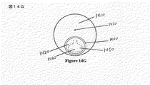
図14Eは、本発明の実施形態によるレンズの中心鉛直線を沿って破断された図14Aと14Cのレンズの断面図を示す。図14Eに見られ得るように、遠距離光学パワー1415は遠距離ゾーンに提供される。大概球状パワー領域と累進光学パワー領域は、各領域によって与えられる光学パワーが近距離ゾーン1460で組み合わさってユーザーのための総近距離追加パワー1465を提供するような互いに光学的連絡にあるように整列される。累進光学パワー領域は、フィッティング・ポイントの下方から始まり、レンズのボトムまたはその上方で終わる。図14Fは、本発明の実施形態によるレンズの前部および後部表面上の図14Aと14Cの光学パワー領域の配置と光学的アライメントを示している発明レンズを前部から示す。図14Gは、本発明の実施形態によるレンズの前部および後部表面状の図14Bと14Cの光学パワー領域の配置と光学的アライメントを示している発明レンズを前部から示す。図14Fと14Gの両方に見られ得るように、累進光学パワー領域は、大概球状パワー領域の一部から始まり、不連続部の下方に間隔を置いている。
FIG. 14E shows a cross-sectional view of the lens of FIGS. 14A and 14C broken along the central vertical line of the lens according to an embodiment of the present invention. As can be seen in FIG. 14E, far-field optical power 1415 is provided in the far-field zone. The generally spherical power region and the progressive optical power region are in optical communication with each other such that the optical power provided by each region combines in the
上述したように、本発明にいくつかの実施形態では、大概球状パワー領域、混合ゾーンおよび累進光学パワー領域は、数学的に組み合わされてレンズの単一表面上に配置され得る。そのような実施形態の例では、レンズの着用者は、遠距離用の矯正を必要とせずに近距離矯正用に+2.25Dを必要とする。図15Aは、本発明の実施形態によるレンズの表面のボトム部分に配置された大概球状パワー領域1510を示す。大概球状パワー領域は光学パワーを屈折により生成し得る。レンズは、遠距離ゾーンの光学パワーと大概球状パワー領域の光学パワーの間で推移する混合ゾーン1520を有する。ただ単に例として、図15Aのレンズでは、大概球状パワー領域は+1.25Dの光学パワーを有し、遠距離ゾーンはプラノ光学パワーを有する。したがって、大概球状パワー領域は増分追加パワーを有し得る。図15Bは、本発明の実施形態によるレンズの表面上に配置された累進光学パワー領域1530を示す。指摘したように、これは、前部凸表面上、後部凹表面上、または前部凸表面と後部凹表面の両者上にあり得る。ただ単に例として、図15Bのレンズでは、累進光学パワー領域は+1.00Dの追加パワーを有する。したがって、累進光学パワー領域は増分追加パワーを有し得る。図15Cは、本発明の実施形態による図15Aに示されたレンズの表面と図15Bに示されたレンズの表面との組み合わせであるレンズの単一表面を示す。ただ単に例として、図15Cのレンズでは、近距離ゾーン光学パワーは、大概球状パワー領域によって与えられる光学パワーの+1.25Dと、累進光学パワー領域によって与えられる光学パワーの+1.00Dとの組み合わせである+2.25Dである。図15Cでは、累進光学パワー領域は、大概球状パワー領域の一部から始まり、混合ゾーンの下方に間隔を置くように光学的に整列されることは注目されるべきである。
As described above, in some embodiments of the present invention, the generally spherical power region, the mixing zone, and the progressive optical power region can be mathematically combined and placed on a single surface of the lens. In an example of such an embodiment, the lens wearer requires + 2.25D for short range correction without requiring long range correction. FIG. 15A shows a generally spherical power region 1510 located at the bottom portion of the surface of the lens according to an embodiment of the present invention. The generally spherical power region can generate optical power by refraction. The lens has a
本発明のいくつかの実施形態では、二つの表面は、二つの表面の幾何学を数学的に一緒に加えてそれにより新しい単一表面を作り出すように組み合わされ得る。そして、この新しい単一表面は、フリー形成によってまたはダイヤモンド・ターニングによって産出され得るモールドから製造され得る。任意の光学的試験所によって表面処理され得る半完成レンズ・ブランクを産出するためにモールドが使用され得る。 In some embodiments of the present invention, the two surfaces may be combined to mathematically add the two surface geometries together thereby creating a new single surface. This new single surface can then be manufactured from a mold that can be produced by free forming or by diamond turning. A mold can be used to produce a semi-finished lens blank that can be surface treated by any optical laboratory.
デカルト座標の幾何学関数の見地から二つの表面のおのおのを記述することによって、図15Aの表面は図15Bに記述された表面と数学的に組み合わされて、二つの表面の組み合わせである図15Cに示された新しい表面を作り出し得る。 By describing each of the two surfaces in terms of Cartesian coordinate geometric functions, the surface of FIG. 15A is mathematically combined with the surface described in FIG. 15B, resulting in the combination of the two surfaces in FIG. 15C. It can produce the indicated new surface.
大概球状パワー領域と混合ゾーンとを規定または産出する表面は、別々の等分セクションに分割され得る。各セクションは、それぞれ、固定曲面または固定湾曲に対する局所的高さまたは局所的カーブとして記述され得る。そのような表面は次式によって記述され得る。

同様に、累進光学パワー領域を規定または産出する表面は、上記セクションと同じサイズである別々の等分セクションに分割され得る。各セクションは、固定表面または固定湾曲に対する局所的な高さまたは局所的な曲面としてそれぞれ記述され得る。そのような表面は次式によって記述され得る。
二つの表面のセクションが同じサイズであるならば、各表面からのセクションを組み合わせることは簡単である。そして、複合表面は、二つの表面の単純な重ね合せによって記述され得る。すなわち
![]()
![]()
このプロセスは本発明の実施形態による図15Dに例証される。 This process is illustrated in FIG. 15D according to an embodiment of the invention.
セクションのサイズは、各表面の正確な表現を達成するために可能な限り小さくあるべきである。二つの表面が組み合わされた後に累進光学パワー領域のさらなる最適化が行なわれ得、または大概球状パワー領域および混合ゾーンとのより良い組み合わせのために累進光学パワー領域があらかじめ最適化され得る。望まれるならば、混合ゾーンは組み合わされ得ず、大概球状パワー領域と累進光学パワー領域だけが組み合わされる。 The section size should be as small as possible to achieve an accurate representation of each surface. Further optimization of the progressive optical power region can be performed after the two surfaces are combined, or the progressive optical power region can be pre-optimized for a better combination with a generally spherical power region and a mixing zone. If desired, the mixing zones cannot be combined, generally only the spherical power region and the progressive optical power region are combined.
二つの表面はまた、メネゼス(Menezes)への米国特許第6,883,916号およびウーリー(Wooley)らへの米国特許第6,955,433号に記載される方法によって組み合わされ得る。それら両者は参照によってそのままここに組み込まれる。 The two surfaces can also be combined by the methods described in US Pat. No. 6,883,916 to Menezes and US Pat. No. 6,955,433 to Wooley et al. Both of which are incorporated herein by reference in their entirety.
発明者は、目の分野で同じ方法でこれまでかつて矯正されていない距離の範囲の重要性を発見した。距離の範囲は、ほぼ29インチとほぼ5フィートの間にあり、一つの机の遠い縁へ合焦するなどの作業にとって特に重要であることが分かった。先行技術では、この距離の範囲は、ほとんど見落とされ、先行技術の定義では遠距離または中距離のいずれかのカテゴリーとひとまとめにされた。したがって、この距離の範囲は、これらのカテゴリーの一つの一部として矯正された。発明者は、この距離の範囲を「遠中距離」と呼ぶ。「遠中距離ゾーン」を名付けられた新しい視力ゾーンは、この発明遠中距離について適切な合焦能力を提供するために発明された。本発明の実施形態は、この遠中距離ゾーンを含み得、このゾーンの光学パワーを最適化して遠中距離について適切な合焦能力を提供し得る。本発明の実施形態は、この遠中距離ゾーンを含み得、レンズ中のこのゾーンの位置を最適化してレンズの適切な人間工学的使用を提供し得る。このゾーンが遠距離ゾーンと中距離ゾーンの間に配置されるとき、それは「上部遠中距離ゾーン」と名付けられる。このゾーンが近距離ゾーンの下方に配置されるとき、それは「下部遠中距離ゾーン」と名付けられる。 The inventor has discovered the importance of distance ranges that have never been corrected in the same way in the eye field. The range of distances is between approximately 29 inches and approximately 5 feet, and has been found to be particularly important for tasks such as focusing on the far edge of one desk. In the prior art, this range of distances was mostly overlooked, and in the prior art definition, it was grouped with either a long or medium distance category. Therefore, this distance range was corrected as part of one of these categories. The inventor calls this range of distances as “far-center distance”. A new vision zone, named “Far-to-Medium Distance Zone”, was invented to provide the proper focusing ability for this invention. Embodiments of the present invention may include this far-medium distance zone, and the optical power of this zone may be optimized to provide proper focusing capability for far-medium distance. Embodiments of the present invention may include this far-medium distance zone and optimize the position of this zone in the lens to provide proper ergonomic use of the lens. When this zone is located between the long-range zone and the mid-range zone, it is termed the “upper mid-range zone”. When this zone is located below the short-range zone, it is termed the “lower far-medium zone”.
一般に、従来技術の多焦点レンズは、遠中距離で適切な合焦能力を提供しないか、遠中距離で限定された合焦能力だけを提供する。たとえば、二焦点の遠距離領域またはゾーンは、ほぼ20フィート以上の光学的無限遠などの遠視野距離で合焦能力を与えるように個々の着用者について処方される。しかしながら、ほとんどの場合、同じ遠距離光学パワーは、ほぼ5フィート以上の距離を見ているときの着用者に十分であるということは注目されるべきである。二焦点の近距離領域またはゾーンは、ほぼ16インチないしほぼ10インチの近視野距離で合焦能力を与えるように処方される。三焦点は、遠視野距離、近視野距離および中視野距離(ほぼ16インチないしほぼ29インチまで)で適切な合焦能力を与える。PALは、遠視野距離と近視野距離の間に明瞭な連続的な視野を提供する。しかしながら、PALの光学パワーは遠距離ゾーンから近距離ゾーンへ連続的に推移するので、PALのこの推移ゾーンの鉛直安定性は非常に限定される。 In general, prior art multifocal lenses do not provide adequate focusing capability at far-medium distances, or provide limited focusing capability at far-medium distances. For example, a bifocal far-field region or zone is prescribed for an individual wearer to provide focusing capability at a far field distance, such as optical infinity of approximately 20 feet or more. However, it should be noted that in most cases, the same long-distance optical power is sufficient for the wearer when viewing a distance of approximately 5 feet or more. The bifocal near field region or zone is formulated to provide focusing capability with a near field distance of approximately 16 inches to approximately 10 inches. Trifocals provide adequate focusing capability at far, near and medium field distances (up to approximately 16 inches to approximately 29 inches). PAL provides a clear continuous field of view between the far and near field distances. However, since the optical power of the PAL continuously shifts from the long distance zone to the short distance zone, the vertical stability of this transition zone of the PAL is very limited.
PALとは異なり、本発明の実施形態は、レンズの特定のゾーンの鉛直安定性を提供し得る。ゾーンの鉛直安定性は、不連続部を引き起こし得る光学パワーのステップによって提供され得る。さらに、本発明の実施形態は、着用者の視力に最も悩ましくないステップの位置を提供し得る。また、本発明の実施形態は、レンズの着用者の顔をある人が見たときにステップが大概見えないようにステップを形成することを提供し得る。また、本発明の実施形態は、ゾーンからゾーンへ眺めるとき、たとえば、遠距離ゾーンから近距離ゾーンへ眺めるときなどに着用者の目がステップを超えて快適に移り得るようにステップを形成することを提供し得る。最後に、本発明のある実施形態では、レンズは、遠距離物体と着用者の目から4ないし5フィート以下にある物体との間で着用者が合焦するときに快適に推移される単一不連続部だけで着用者の目からのほぼ4ないし5フィートとほぼ10インチないし12インチとの間で連続的な不断な合焦能力を提供し得る。本発明のさらに別の実施形態では、光学パワーのステップは遠距離ゾーンと中距離ゾーンの間に生じ、それによって、レンズは、遠距離物体と着用者の目からほぼ29インチ以下にある物体との間で着用者が合焦するときに快適に推移される単一不連続部だけで着用者の目からのほぼ29インチとほぼ10インチないし12インチとの間で連続的な不断な合焦能力を与える。 Unlike PAL, embodiments of the present invention may provide vertical stability of specific zones of the lens. The vertical stability of the zone can be provided by optical power steps that can cause discontinuities. Furthermore, embodiments of the present invention may provide a step location that is least plagued by the wearer's vision. Embodiments of the present invention may also provide for forming the steps so that the steps are not generally visible when a person sees the face of the lens wearer. Also, embodiments of the present invention form steps so that the wearer's eyes can move comfortably across steps when viewing from zone to zone, for example, when viewing from a long distance zone to a short distance zone. Can provide. Finally, in certain embodiments of the invention, the lens is a single lens that is comfortably transitioned when the wearer is in focus between a distant object and an object that is 4 to 5 feet or less from the wearer's eye. The discontinuity alone may provide a continuous constant focusing ability between approximately 4-5 feet from the wearer's eyes and approximately 10-12 inches. In yet another embodiment of the present invention, the optical power step occurs between the far zone and the middle zone, so that the lens is located between the far object and an object that is approximately 29 inches or less from the wearer's eye. Continuous, continuous focusing between approximately 29 inches and approximately 10 inches to 12 inches from the wearer's eyes with only a single discontinuity that transitions comfortably when the wearer focuses between Give ability.
本発明の実施形態では、遠中距離ゾーンと中距離ゾーンに矯正総光学パワーが提供されることを保証するように大概球状パワー領域と累進光学パワー領域を整列させることが必要であり得る。遠中距離ゾーンは、近距離追加パワーのほぼ20%とほぼ44%の間の追加パワーを一般に有する。中距離ゾーンは、近距離追加パワーのほぼ45%とほぼ55%の間の追加パワーを一般に有する。着用者の視線がさまざまなゾーン(遠距離ゾーン、遠中距離ゾーン、中距離ゾーンおよび近距離ゾーン)の間を推移するときのための使用可能で人間工学的に実現可能なレンズを作り出すようにこれらの領域を整列し位置決めすることもまた必要であり得る。結局、最適な中距離矯正および/または遠中距離矯正を保証するために遠距離視力矯正と近距離視力矯正の間に存在する光学パワーの勾配を設計することもまた必要であり得る。 In embodiments of the present invention, it may be necessary to align the generally spherical power region and the progressive optical power region to ensure that the corrected total optical power is provided to the far and medium distance zones. The far-medium distance zone generally has an additional power between approximately 20% and approximately 44% of the short-range additional power. The mid-range zone generally has an additional power between approximately 45% and approximately 55% of the short-range additional power. To create a usable and ergonomically feasible lens for when the wearer's line of sight transitions between different zones (far zone, far middle zone, middle zone and short zone) It may also be necessary to align and position these regions. Eventually, it may also be necessary to design the optical power gradient that exists between the long distance vision correction and the near distance vision correction to ensure optimal medium distance correction and / or long distance correction.
本発明の実施形態では、大概球状パワー領域は、フィッティング・ポイントの下方ほぼ0mmとほぼ7mmの間に配置され得る。本発明の別の実施形態では、大概球状パワー領域は、フィッティング・ポイントの下方ほぼ2mmとほぼ5mmの間に配置され得る。本発明の実施形態では、累進光学パワー領域は、大概球状パワー領域の一部大概球状パワー領域のトップ・エッジの下方ほぼ2mmないしほぼ10mmから始まり得る。本発明の別の実施形態では、累進光学パワー領域は、大概球状パワー領域の一部大概球状パワー領域のトップ・エッジの下方ほぼ4mmないしほぼ8mmから始まり得る。本発明の実施形態では、遠中距離のパワーは、フィッティング・ポイントの下方ほぼ3mmとほぼ4mmの間から始まり、チャンネルの下ほぼ4mmまで延び得る。本発明の実施形態では、中距離パワーは、遠中距離ゾーンの後に始まり、チャンネルの下ほぼ3mmないしほぼ4mmまで延び得る。前述の測定値は単に代表的であり、本発明を限定する意図はない。 In embodiments of the invention, the generally spherical power region may be located between approximately 0 mm and approximately 7 mm below the fitting point. In another embodiment of the invention, the generally spherical power region may be located between approximately 2 mm and approximately 5 mm below the fitting point. In an embodiment of the present invention, the progressive optical power region may begin from approximately 2 mm to approximately 10 mm below the top edge of a portion of the generally spherical power region. In another embodiment of the present invention, the progressive optical power region may begin from approximately 4 mm to approximately 8 mm below the top edge of a portion of the generally spherical power region. In an embodiment of the present invention, the mid-range power may begin between approximately 3 mm and approximately 4 mm below the fitting point and extend to approximately 4 mm below the channel. In an embodiment of the present invention, the medium range power may begin after the far mid range zone and extend from about 3 mm to about 4 mm below the channel. The above measurements are merely representative and are not intended to limit the invention.
大概球状パワー領域と累進光学パワー領域が整列および位置決めされないならば、レンズのユーザーはレンズの使用可能部に適切な視力矯正を有しないだろう。たとえば、大概球状パワー領域がフィッティング・ポイントの非常に上方に配置されるならば、着用者は前方を真っすぐに眺めるときに遠距離視野について強すぎる光学パワーを有し得る。別の例として、低追加パワー累進光学パワー領域がレンズ中に高すぎて配置されるならば、大概球状パワー領域と累進光学パワー領域によって提供される中距離ゾーン中の複合光学パワーは着用者にとって高すぎになり得る。 If the generally spherical power region and the progressive optical power region are not aligned and positioned, the lens user will not have proper vision correction in the usable part of the lens. For example, if the generally spherical power region is located very high above the fitting point, the wearer may have too strong optical power for the far field when looking straight ahead. As another example, if the low additional power progressive optical power region is placed too high in the lens, the combined optical power in the medium distance zone provided by the generally spherical power region and the progressive optical power region is Can be too expensive.
図16と図17は、本発明の実施形態による+1.25Dの近距離追加パワーを有している三つの従来のPAL設計(エシロール(Essilor)によって商標登録されたエシロール・フィジオ(Essilor Physio)(登録商標)レンズ、エシロール(Essilor)によって商標登録されたエシロール・エリプス(Essilor Ellipse)(登録商標)レンズ、シャミル・オプティカル(Shamir Optical)によって商標登録されたシャミル・ピッコロ(Shamir Piccolo)(登録商標)レンズ)を示す。図16は、ロトレックス(Rotlex)によって商標登録されたロトレックス・クラス・プラス(Rotlex Class Plus)(登録商標)によって測定された三つのレンズについての追加パワー勾配を示す。図17は、ロトレックス・クラス・プラス(Rotlex Class Plus)(登録商標)によって測定された三つのレンズ中の追加パワーのチャンネルを下へフィッティング・ポイントから3mmごとに取った測定値を示す。 FIGS. 16 and 17 show three conventional PAL designs (Essilor Physio, trademarked by Essilor) with a near-field additional power of + 1.25D according to embodiments of the present invention. Registered lens, Essilor Ellipse (R) lens registered by Essilor, Shamir Piccolo (R) registered by Shamir Optical Lens). FIG. 16 shows the additional power gradient for the three lenses measured by the Rotlex Class Plus®, registered by Rotlex. FIG. 17 shows measured values taken every 3 mm from the fitting point down the channel of additional power in the three lenses measured by the Rotorx Class Plus®.
図18は、本発明の三つの実施形態の追加パワーのチャンネルを下へフィッティング・ポイントから3mmごとに取った測定値を示す。これらの実施形態では、図16と図17の三つのレンズは、+1.00Dの光学パワーを有している大概球状パワー領域に光学的連絡して置かれる。これらの実施形態では、累進光学パワー領域はフィッティング・ポイントから始まり、大概球状パワー領域のトップ・エッジはフィッティング・ポイントのちょうど下方に置かれる。図18から見られ得るように、フィッティング・ポイントの下方9mmでのレンズの追加パワーは強すぎる。フィッティング・ポイントの下方9mmでのレンズの領域は一般に中距離ゾーンの一部になる。+2.25D近距離追加パワーに対して、中距離追加パワーは+1.12Dであるべきである。しかしながら、エシロール・フィジオ(Essilor Physio)(登録商標)実施形態はフィッティング・ポイントの下方9mmで+1.63D追加パワーを有し、エシロール・エリプス(Essilor Ellipse)(登録商標)実施形態はフィッティング・ポイントの下方9mmで+1.82D追加パワーを有し、シャミル・ピッコロ(Shamir Piccolo)(登録商標)実施形態はフィッティング・ポイントの下方9mmで+1.68D追加パワーを有する。中距離ゾーンに強すぎる追加パワーがあるので、レンズのユーザーは、まるで彼または彼女の目が引っぱっているか交差しているかのように感じ得る。これは頭痛を引き起こし得る。またユーザーは、このゾーンを通して適切に合焦するために彼または彼女の目の近くに物体を保持しなければならない。したがって、大概球状パワー領域と累進光学パワー領域の光学パワー、配置およびアラインメントが最適化されないならば、結果のレンズは次のもの、貧弱な視力人間工学、貧弱な視力快適さおよび貧弱な視力明瞭さの一つ以上を有するであろう。
FIG. 18 shows measurements taken every 3 mm from the fitting point down the additional power channel of the three embodiments of the present invention. In these embodiments, the three lenses of FIGS. 16 and 17 are placed in optical communication with a generally spherical power region having an optical power of +1.00 D. In these embodiments, the progressive optical power region starts at the fitting point, and the top edge of the generally spherical power region is located just below the fitting point. As can be seen from FIG. 18, the additional power of the lens at 9 mm below the fitting point is too strong. The area of the
別の例として、図19は、ロトレックス・クラス・プラス(Rotlex Class Plus)(登録商標)によって測定された左側の本発明の実施形態と右側のエシロール・フィジオ(Essilor Physio)(登録商標)レンズとの両方の追加パワー勾配を示す。実施形態とフィジオ(登録商標)レンズの両方は、+2.25Dの追加パワーを有する。実施形態は、+1.25Dの光学パワーを有している大概球状パワー領域と、+1.00Dの追加パワーを有している累進光学パワー領域とを有する。累進光学パワー領域のトップはフィッティング・ポイントのちょうど下方から始まり、大概球状パワー領域のトップはフィッティング・ポイントの下方4mmに配置される。したがって、大概球状パワー領域がレンズに光学パワーを加え始める前に、累進光学パワー領域だけが増大光学パワーを与えるレンズの領域がある。図20は、ロトレックス・クラス・プラス(Rotlex Class Plus)(登録商標)によって測定された図19の二つのレンズ中の追加パワーのチャンネルを下へフィッティング・ポイントから3mmごとに取った測定値を示す。本発明のこの実施形態は、フィッティング・ポイントから9mmに+1.10Dの追加パワーを有するエシロール・フィジオ(Essilor Physio)(登録商標)と比較して、フィッティング・ポイントから9mmに+1.60Dの追加パワーを有する。前のように、大概球状パワー領域と累進光学パワー領域の光学パワー、配置およびアラインメントが最適化されていないならば、結果のレンズは、貧弱な視力人間工学、貧弱な視力快適さおよび貧弱な視力明瞭さを有するであろう。これは、図18と20のフィッティング・ポイントの下方15mmにあるように、矯正全追加パワーがレンズによって提供するときであっても真実である。 As another example, FIG. 19 shows an embodiment of the present invention on the left and an Essilor Physio® lens on the right, as measured by a Rolex Class Plus®. And both show additional power gradients. Both the embodiment and the Physio® lens have an additional power of + 2.25D. Embodiments have a generally spherical power region with an optical power of + 1.25D and a progressive optical power region with an additional power of + 1.00D. The top of the progressive optical power region starts just below the fitting point, and the top of the mostly spherical power region is located 4 mm below the fitting point. Thus, there is a region of the lens where only the progressive optical power region provides increased optical power before the generally spherical power region begins to apply optical power to the lens. FIG. 20 shows the measured values taken every 3 mm from the fitting point down the channel of additional power in the two lenses of FIG. 19 as measured by the Rotorx Class Plus®. Show. This embodiment of the present invention provides an additional power of +1.60 D at 9 mm from the fitting point compared to Essilor Physio®, which has an additional power of +1.10 D at 9 mm from the fitting point. Have As before, if the optical power, placement and alignment of the mostly spherical and progressive optical power regions are not optimized, the resulting lens will have poor visual ergonomics, poor visual comfort and poor visual acuity Will have clarity. This is true even when the corrective total additional power is provided by the lens, as 15 mm below the fitting point in FIGS.
したがって、たとえ本発明のこれらの実施形態が最新のPALsと比較して多数の優れた特性(たとえば少ない不所望な非点収差)を有するとしても、そのようなレンズはユーザーによって拒絶されるであろうことは明白に違いない。本発明の実施形態は、中距離ゾーンに強すぎる追加パワーを有し、フィッティング・ポイントからレンズのボトムまでの光学パワー勾配は急峻すぎる。 Thus, even though these embodiments of the present invention have a number of superior properties (eg, less unwanted astigmatism) compared to modern PALs, such lenses will be rejected by the user. Deaf must be obvious. Embodiments of the present invention have additional power that is too strong in the mid-range zone, and the optical power gradient from the fitting point to the bottom of the lens is too steep.
エシロール・フィジオ(Essilor Physio)(登録商標)レンズについて図18と図20に示される追加パワー測定値を比較することによって、図17のエシロール・フィジオ(Essilor Physio)(登録商標)レンズに+の1.00Dの球状パワー領域を加え、それによって図20のエシロール・フィジオ(Essilor Physio)(登録商標)レンズに近づけ得ないことは明白に違いない。したがって、それ大概球状パワー領域および/または累進光学パワー領域は、適切な中距離矯正および/または遠中距離矯正を提供するために遠距離ゾーンと近距離ゾーンの間の光学パワーの勾配を考慮に入れて設計されなければならないことは明白に違いない。 By comparing the additional power measurements shown in FIG. 18 and FIG. 20 for the Essilor Physio® lens, the Essilor Physio® lens of FIG. Obviously, a .00D spherical power region could be added, thereby making it inaccessible to the Essilor Physio® lens of FIG. Thus, generally the spherical power region and / or progressive optical power region takes into account the gradient of optical power between the long and short distance zones in order to provide proper medium and / or long and medium distance corrections. It must be obvious that it must be designed in.
図21は、本発明の実施形態によるレンズの四つの領域、遠距離ゾーン2110と上部遠中距離ゾーン2120と中距離ゾーン2130と近距離ゾーン2140を示す。これらの領域は実寸どおりに示されていない。上部遠中距離ゾーンは、点Hから点Iまでの高さと、点Aから点Bまでの幅とを有し得る。中距離ゾーンは、点Iから点Jまでの高さと、点Cから点Dまでの幅とを有し得る。近距離ゾーンは、点Jから点Gまでの高さと、点Eから点Fまでの幅とを有し得る。本発明のある実施形態では、発明レンズは、着用者に遠距離ゾーンと近距離ゾーンについて適切な矯正を提供し、着用者が遠中距離と中距離で適切に見ることを可能にする光学パワーの最適化勾配を提供し得る。本発明のある実施形態では、レンズは、上部遠中距離ゾーンの視力の鉛直安定性および/または中距離ゾーンの視力の鉛直安定性を有し得る。遠中距離ゾーンを有しない本発明の実施形態では、中距離ゾーンは、視力の増大された鉛直安定性を有し(すなわち、さらに鉛直に延び)得る。
FIG. 21 shows four regions of a lens according to an embodiment of the present invention: a
追加遠中距離領域が近距離ゾーンの下方に設けられ得る。そのような実施形態では、この領域は「下部」遠中距離ゾーンと呼ばれ得、遠距離領域と中距離領域の間の遠中距離領域は「上部」遠中距離領域と呼ばれ得る。上部および下部遠中ゾーンは同じ光学パワーを有し得る。下部遠中ゾーンは、老眼の着用者が下方を眺めるときに彼または彼女の足または床をより容易に見ることを可能にするために本発明の実施形態に含まれ得る。これは、階段を上り下りするときに追加の安全性を提供し得る。 An additional far-medium range area may be provided below the short-range zone. In such an embodiment, this region may be referred to as the “lower” far-medium zone and the far-medium region between the far and middle regions may be referred to as the “upper” far-medium region. The upper and lower far-inner zones can have the same optical power. A lower far middle zone may be included in embodiments of the present invention to allow a presbyopic wearer to more easily see his or her foot or floor when looking down. This may provide additional safety when going up and down stairs.
本発明の実施形態は、レンズの領域間に一つ以上の不連続部を含み得る。一般に、本発明の実施形態は単一不連続を含むだけである。不連続部は、レンズの二つの異なる領域間の不連続表面または不連続光学パワーによって引き起こされ得る。不連続部は、光学パワーのステップ増またはステップ減によって引き起こされ得る。不連続部は、レンズを通して眺めるときに知覚画像乱れにつながるレンズの表面またはレンズの光学パワーの任意の変化によって規定される。ただ単に例として、発明者は、さまざまなレンズを製造し、眼鏡レンズが一般に着用されるか仕方に調和する目からの距離にレンズが配置されるとき、ほぼ0.10D未満の光学パワー不連続部をレンズが有するときに画像乱れを知覚し難いことを見いだした。しかしながら、ほぼ0.10Dないし0.12Dよりも大きい光学パワー不連続部はほとんどの場合に視覚的に検知され得る。さらに、レンズの着用者によって知覚され得るような光学パワー不連続部は、たとえば、コンピューター・スクリーンを見ることなどのある視覚的作業中の着用者の視力に邪魔になり得る。不連続部について上述した光学パワー値は単に代表的であり、不連続部は、レンズに通して眺めるときに画像乱れを知覚する能力につながるレンズの表面または光学パワーの任意の変化として規定されることは注目されるべきである。 Embodiments of the invention can include one or more discontinuities between the regions of the lens. In general, embodiments of the present invention only include a single discontinuity. The discontinuity can be caused by a discontinuous surface or discontinuous optical power between two different regions of the lens. The discontinuity can be caused by a step increase or decrease in optical power. A discontinuity is defined by any change in the lens surface or lens optical power that leads to perceptual image distortion when viewed through the lens. By way of example only, the inventor has produced various lenses and optical power discontinuities of less than approximately 0.10 D when the lenses are placed at a distance from the eye that matches the manner in which spectacle lenses are generally worn. We found that it is difficult to perceive image disturbance when the lens has a part. However, optical power discontinuities greater than approximately 0.10D to 0.12D can be visually detected in most cases. In addition, optical power discontinuities that can be perceived by the lens wearer can interfere with the wearer's visual acuity during visual tasks such as, for example, looking at a computer screen. The optical power values described above for the discontinuities are merely representative, and the discontinuities are defined as any change in the lens surface or optical power that leads to the ability to perceive image distortion when viewed through the lens. That should be noted.
発明者は、ある不連続部が他よりもより目立ちおよび/または邪魔であることをさらに確証した。したがって、本発明の実施形態は、より少なく目立ちおよび/またはより少なく邪魔である一つ以上の不連続部を含み得る。発明者は、レンズの遠距離ゾーンと上部遠中距離ゾーンの間の不連続部は、中距離ゾーン、近距離ゾーン内、または中距離ゾーンと近距離ゾーンの間にある不連続部よりはるかによくユーザーによって視覚的に許容されることを見いだした。さらに、発明者は、不連続部の少なくとも一部を混合する混合ゾーンの幅が狭いほど、目は、混合ゾーンによって作り出される任意の画像乱れまたは曇りを超えてより速く推移するという事実のため、目は不連続部を超えて良好に推移することを確証した。したがって不連続部は混合されるべきでないことを示すように思われるが、ほとんど目に見えない不連続部を作り出すために不連続部を混合する肯定的な見場の効果によってバランスが取られなければならない。 The inventors have further established that certain discontinuities are more noticeable and / or disturbing than others. Thus, embodiments of the present invention may include one or more discontinuities that are less noticeable and / or less disturbing. The inventor has found that the discontinuity between the lens's far zone and the upper far-middle zone is much more than the discontinuity in the middle zone, in the near zone, or between the middle zone and the near zone I have found that it is often visually acceptable by users. In addition, the inventors have shown that the narrower the mixing zone that mixes at least some of the discontinuities, the faster the eye will transition beyond any image disturbance or haze created by the mixing zone. It was confirmed that the eye transitioned well beyond the discontinuity. Thus it seems to indicate that the discontinuity should not be mixed, but must be balanced by the positive visual effect of mixing the discontinuities to create a discontinuity that is almost invisible. I must.
本発明の実施形態は一つ以上の不連続部を備え、不連続部は、+0.12D以上の光学パワーのステップずつ引き起こされ得る。実施形態は、ほぼ2.0mm未満またはほぼ1.0mmと0.5mmの間の幅を有している混合ゾーンによって少なくとも部分的に混合される単一の不連続部を有し得る。この幅の混合ゾーンはダイヤモンド・ターニングによって生成され得る。しかしながら、本発明の別の実施形態では、不連続部は混合されない。本発明の実施形態では、不連続部は、ほぼ+0.50Dを超える、ほとんどの場合にはほぼ+0.25Dを超える光学パワーのステップによって作り出され得る。光学パワーのステップおよびしたがって不連続部は、いつもとは限らないが通常は、発明レンズの遠距離ゾーンと遠中距離ゾーンの間に配置される。あるいは、レンズが遠中距離ゾーンを有しないとき、不連続部は通常はレンズの遠距離ゾーンと中距離ゾーンの間に配置される。図25と26は、半発明の実施形態による累進光学パワー領域が始まる前の光学パワーのそのようなステップ増を示す。 Embodiments of the present invention comprise one or more discontinuities, which can be caused by steps of optical power greater than + 0.12D. Embodiments may have a single discontinuity that is at least partially mixed by a mixing zone having a width of less than approximately 2.0 mm or between approximately 1.0 mm and 0.5 mm. This width of the mixing zone can be created by diamond turning. However, in another embodiment of the invention, the discontinuities are not mixed. In embodiments of the present invention, the discontinuities can be created by steps of optical power greater than approximately + 0.50D, and in most cases greater than approximately + 0.25D. The optical power steps and thus the discontinuities are usually, but not always, located between the far and middle distance zones of the inventive lens. Alternatively, when the lens does not have a far-middle distance zone, the discontinuity is usually placed between the far and middle distance zones of the lens. Figures 25 and 26 illustrate such a step increase in optical power before the progressive optical power region begins according to the semi-inventive embodiment.
本発明のすべての実施形態は、光学パワーの三つの使用可能ゾーン、遠距離ゾーンと中距離ゾーンと近距離ゾーンを有する能力を与える。本発明の実施形態はまた、第四ゾーン、上部遠中距離ゾーンと、いくつかの実施形態では、第五ゾーン、下部遠中距離ゾーンとを有する能力を提供し得る。本発明の実施形態は以下のことをし得る。 All embodiments of the present invention provide the ability to have three usable zones of optical power: a long zone, a medium zone and a short zone. Embodiments of the present invention may also provide the ability to have a fourth zone, an upper far and middle distance zone, and in some embodiments, a fifth zone, a lower far and middle distance zone. Embodiments of the present invention can:
a) チャンネルの長さを増大させて光学パワーの追加2mmないし3mm平坦域を与えて上部遠中距離矯正を提供する。そのような光学パワー・ゾーンは、その人のコンピューターを使用するときやその人の机の縁を眺めるときに有用であり得る。チャンネル長を増大させることは、レンズを収容する眼鏡フレームの鉛直寸法に依存する可能性があり得ないことは注目されるべきである。 a) Increase the length of the channel to provide an additional 2 to 3 mm plateau of optical power to provide upper far-medium distance correction. Such an optical power zone can be useful when using the person's computer or looking at the edge of the person's desk. It should be noted that increasing the channel length may not depend on the vertical dimensions of the spectacle frame that houses the lens.
b) チャンネルの長さを増大させて光学パワーの追加2mmないし3mm平坦域を与えて下部遠中距離矯正を提供する。そのような光学パワー・ゾーンは、床を眺めるときや階段を上り下りするときに有用であり得る。チャンネル長を増大させることは、レンズを収容する眼鏡フレームの鉛直寸法に依存する可能性があり得ないことは注目されるべきである。 b) Increase the channel length to provide an additional 2 to 3 mm plateau of optical power to provide lower far-medium distance correction. Such an optical power zone can be useful when looking at the floor or going up and down stairs. It should be noted that increasing the channel length may not depend on the vertical dimensions of the spectacle frame that houses the lens.
c) 一つ以上の不連続部を利用する。一つ以上の不連続部は、光学パワーの一つ以上のステップによって引き起こされ得、ステップは、光学パワーのステップ増またはステップ減のいずれかである。不連続部は、光学パワーを増減するためにレンズ土地を、もしあるにしても、非常にほとんど使用しないので、チャンネルは、チャンネルの長さを延ばすことなく光学パワーの平坦域を与えるように設計され得る。光学パワーのステップが大きいほど、レンズ中のより多くの土地が光学パワー平坦域を提供され得ることに注意することは重要である。発明の実施形態では、光学パワーの平坦域は不連続部の後に提供されて遠中距離矯正を提供する。これは、チャンネルの長さを加えることなく遂行する。図22は、光学パワーの二つの平坦域2230と2240を有している本発明の実施形態を示し、図23は、光学パワーの三つの平坦域2330と2340と2350を有している本発明の実施形態を示す。
c) Use one or more discontinuities. One or more discontinuities can be caused by one or more steps of optical power, where a step is either a step increase or a step decrease in optical power. The discontinuity uses very little, if any, lens land to increase or decrease the optical power, so the channel is designed to give a plateau of optical power without extending the length of the channel Can be done. It is important to note that the larger the optical power step, the more land in the lens can be provided with the optical power plateau. In an embodiment of the invention, a plateau of optical power is provided after the discontinuity to provide far-medium distance correction. This is accomplished without adding channel length. FIG. 22 shows an embodiment of the invention having two plateaus 2230 and 2240 of optical power, and FIG. 23 shows the invention having three
d) チャンネルの長さを同じに保つが、光学パワーのさまざまなゾーン間で光学パワーをより速く傾斜させる。これは着用者の視力快適さと眼精疲労に関する問題に通常つながることは注目されるべきである。 d) Keep the channel length the same, but ramp the optical power faster between different zones of optical power. It should be noted that this usually leads to problems with the wearer's visual comfort and eye strain.
e) 近距離ゾーンのすぐ下方に光学パワーのステップ減を使用して下部遠中距離ゾーンを与える。レンズの近距離部の下方に十分なレンズ土地があるならば、下部遠中距離ゾーンが可能なだけであり得ることは注目されるべきである。 e) Use the optical power step reduction just below the short-range zone to give the lower far-medium zone. It should be noted that the lower far-medium zone may only be possible if there is enough lens land below the short-range part of the lens.
図22は、遠距離ゾーンを近距離ゾーンに連結している累進光学パワー領域を含んでいる本発明の実施形態の中心鉛直中央線に沿った光学パワーを示す。図は実寸どおりに描かれていない。遠距離ゾーンの光学パワーはプラノとして示され、したがってX軸2210によって表わされる。累進光学パワー領域はレンズのフィッティング・ポイント2220から始まる。あるいは、累進光学パワー領域はフィッティング・ポイントの下方から始まり得る。累進光学パワー領域の光学パワーはチャンネルの長さにわたって増大するが、累進光学パワー領域はチャンネル内に光学パワーの二つの平坦域を提供し得る。第一平坦域2230は上部遠中距離矯正を提供し、第二平坦域2240は中距離矯正を提供する。あるいは、累進光学パワー領域は、中距離矯正または遠中距離矯正のいずれかを提供する光学パワーの単一平坦域を提供する。光学パワーの第一平坦域は、ほぼ1mmとほぼ6mmの間またはほぼ2mmとほぼ3mmの間のチャンネルに沿った鉛直長さを有し得る。しかしながら、すべての場合に、光学パワーの平坦域はほぼ1mmの鉛直長さを有する。二つの平坦域を備える場合、光学パワーの第一平坦域の後、累進光学パワー領域によって与えられる光学パワーは、光学パワーの第二平坦域まで増大する。光学パワーの第二平坦域は、ほぼ1mmとほぼ6mmの間またはほぼ2mmとほぼ3mmの間のチャンネルに沿った鉛直長さを有し得る。光学パワーの第二平坦域の後、累進追加領域によって与えられる光学パワーは、総近距離光学パワーが2250に到達するまで増大する。近距離光学パワーが達成された後、累進光学パワー領域によって与えられる光学パワーは減少し始め得る。光学パワーが、近距離ゾーンの追加パワーのほぼ20%ないしほぼ44%の間まで減少するならば、下部遠中ゾーンが提供され得る。 FIG. 22 shows the optical power along the central vertical centerline of an embodiment of the present invention that includes a progressive optical power region connecting the far zone to the near zone. The figure is not drawn to scale. The optical power of the far zone is shown as plano and is therefore represented by the X axis 2210. The progressive optical power region begins at the lens fitting point 2220. Alternatively, the progressive optical power region can begin below the fitting point. While the optical power in the progressive optical power region increases over the length of the channel, the progressive optical power region can provide two plateaus of optical power within the channel. The first plateau 2230 provides upper far-medium correction and the second plateau 2240 provides medium-range correction. Alternatively, the progressive optical power region provides a single plateau of optical power that provides either medium distance correction or far-medium distance correction. The first plateau of optical power may have a vertical length along the channel between approximately 1 mm and approximately 6 mm or between approximately 2 mm and approximately 3 mm. However, in all cases, the optical power plateau has a vertical length of approximately 1 mm. With two plateaus, after the first plateau of optical power, the optical power provided by the progressive optical power region increases to the second plateau of optical power. The second plateau of optical power may have a vertical length along the channel between approximately 1 mm and approximately 6 mm or between approximately 2 mm and approximately 3 mm. After the second plateau of optical power, the optical power provided by the progressive addition region increases until the total near field optical power reaches 2250. After short range optical power is achieved, the optical power provided by the progressive optical power region may begin to decrease. If the optical power is reduced to between approximately 20% and approximately 44% of the additional power in the short-range zone, a lower mid-range zone can be provided.
図23は、遠距離ゾーンを近距離ゾーンに連結している累進光学パワー領域を含んでいる本発明の実施形態の中心鉛直中央線に沿った光学パワーを示す。図は実寸どおりに描かれていない。遠距離ゾーンの光学パワーはプラノとして示され、したがってX軸2310によって表わされる。累進光学パワー領域はレンズのフィッティング・ポイント2320から始まる。あるいは、累進光学パワー領域はフィッティング・ポイントの下方から始まり得る。累進光学パワー領域の光学パワーはチャンネルの長さにわたって増大するが、累進光学パワー領域はチャンネル内に光学パワーの三つの平坦域を提供し得る。第一平坦域2330は上部遠中距離矯正を提供し、第二平坦域2340は中距離矯正を提供し、第三平坦域2350は近距離矯正を提供する。光学パワーの第一平坦域は、ほぼ1mmとほぼ6mmの間またはほぼ2mmとほぼ3mmの間のチャンネルに沿った鉛直長さを有し得る。しかしながら、すべての場合に、光学パワーの平坦域はほぼ1mmの鉛直長さを有する。光学パワーの第一平坦域の後、累進光学パワー領域によって与えられる光学パワーは、光学パワーの第二平坦域まで増大する。光学パワーの第二平坦域は、ほぼ1mmとほぼ6mmの間またはほぼ2mmとほぼ3mmの間のチャンネルに沿った鉛直長さを有し得る。光学パワーの第二平坦域の後、累進光学パワー領域によって与えられる光学パワーは、光学パワーの第三平坦域まで増大する。光学パワーの第三平坦域は、ほぼ1mmとほぼ6mmの間またはほぼ2mmとほぼ3mmの間のチャンネルに沿った鉛直長さを有し得る。近距離光学パワーが2360で達成された後、累進光学パワー領域によって与えられる光学パワーは減少し始め得る。光学パワーが、近距離ゾーンの追加パワーのほぼ20%ないしほぼ44%の間まで減少するならば、下部遠中ゾーンが提供され得る。
FIG. 23 illustrates the optical power along the central vertical centerline of an embodiment of the present invention that includes a progressive optical power region connecting the far zone to the near zone. The figure is not drawn to scale. The optical power of the far zone is shown as plano and is therefore represented by the X axis 2310. The progressive optical power region begins at the lens fitting point 2320. Alternatively, the progressive optical power region can begin below the fitting point. While the optical power in the progressive optical power region increases over the length of the channel, the progressive optical power region can provide three plateaus of optical power within the channel. The first plateau 2330 provides upper far-medium distance correction, the second plateau 2340 provides medium-range correction, and the
図24は、大概球状パワー領域と、不連続部と、遠距離ゾーンを近距離ゾーンに連結している累進光学パワー領域とを含んでいる本発明の実施形態の中心鉛直中央線に沿った光学パワーを示す。図は実寸どおりに描かれていない。遠距離ゾーンの光学パワーはプラノとして示され、したがってX軸2410によって表わされる。累進光学パワー領域は、レンズのフィッティング・ポイント2420またはその近くから始まる。不連続部2430は大概球状パワー領域によって引き起こされ得、それは、光学パワーのステップを引き起こし、光学パワー2440を与える。累進光学パワー領域は不連続部の上方から始まり得る。この場合、累進光学パワー領域の始まりは、遠距離ゾーンの光学パワーを測定し、そしてレンズの光学パワーが徐々にプラスの光学パワーに増大またはマイナスの光学パワーに低減し始める不連続部の上方にレンズのエリアまたは領域を配置することによって配置され得る。不連続部の直前と不連続部の直後の光学パワー間の差は「光学パワーのステップ」と呼ばれる。光学パワーが連続部の前から連続部の後ろに増大するならば「光学パワーのステップ増」が生じる。光学パワーが連続部の前から連続部の後ろに減少するならば「光学パワーのステップ減」が生じる。したがって、累進光学パワー領域が不連続部の上方から始まるならば、不連続部のすぐ前ではレンズの総光学パワーは累進光学パワー領域と遠距離ゾーンの光学パワーであり、不連続部のすぐ後ろではレンズの総光学パワーは、光学パワーのステップによって引き起こされる光学パワーと累進追加領域と遠距離ゾーンの光学パワーである。あるいは、累進光学パワー領域は、不連続部のすぐ前ではレンズの総光学パワーが遠距離光学パワーであり、不連続部のすぐ後ろで累進光学パワー領域がひとたび始まれば、レンズの総光学パワーは、光学パワーのステップによって引き起こされる光学パワーと累進追加領域と遠距離ゾーンの光学パワーであるように不連続部の下方から始まり得る。累進光学パワー領域は不連続部のすぐ後ろから始まり得る。あるいは、累進光学パワー領域は不連続部から1ミリメートル以上から始まり、それにより中距離視野や上部遠中距離視野に有用であり得る光学パワーの平坦域2450を作り出し得る。本発明のいくつかの実施形態では、累進光学パワー領域は、レンズの総光学パワーを増大させる正の光学パワーを有する前にレンズの総光学パワーを減少させるような負の光学パワー2460を有し得る。たとえば、光学パワーのステップによって引き起こされる光学パワーは適切な遠中距離視野に必要とされる光学パワーよりも高くなり得る。この場合、不連続部またはそのすぐ後ろの累進光学パワー領域の一部は、適切な上部遠中距離矯正を提供するためにレンズの光学パワーを減少させ得る。累進光学パワー領域はそれから、適切な中距離矯正2470を提供するために光学パワーが増大し得る。累進光学パワー領域の光学パワーは全近距離光学パワー2480までさらに増大し得、その後、再び減少し始め得る。したがって、大概球状パワー領域と累進光学パワー領域はそれぞれレンズの総追加パワーを一緒に提供する増分追加パワーを有し得る。光学パワーが、近距離ゾーンの追加パワーのほぼ20%ないしほぼ44%の間まで減少するならば、下部遠中ゾーンが提供され得る。
FIG. 24 shows an optical along the central vertical centerline of an embodiment of the present invention that includes a generally spherical power region, a discontinuity, and a progressive optical power region connecting the far zone to the near zone. Indicates power. The figure is not drawn to scale. The optical power of the far zone is shown as plano and is therefore represented by the X axis 2410. The progressive optical power region begins at or near the lens
累進光学パワー領域が不連続部の上方から始まる本発明の実施形態では、累進光学パワー領域によって与えられる光学パワーは初期にゼロまたは負であり得る。不連続部は、光学パワーのステップによって引き起こされ得る。光学パワーのステップによって引き起こされる光学パワーは、適切な中距離矯正または遠中距離矯正に必要とされる光学パワーとほぼ等しくなり得る。したがって、累進光学パワー領域によって与えられる初期光学パワーがゼロならば、不連続部の後の複合光学パワーは適切な中距離矯正または遠中距離矯正になるであろう。同様に、光学パワーのステップによって引き起こされる光学パワーは、適切な中距離矯正または遠中距離矯正に必要とされる光学パワーより大きくなり得る。したがって、累進光学パワー領域によって与えられる初期光学パワーが負であるならば、不連続部の後の複合光学パワーは適切な中距離矯正または遠中距離矯正になるであろう。いずれの場合も、累進光学パワー領域が初期に正の光学パワーを与えるならば、不連続部の後の複合光学パワーは強すぎるであろう。これは、図16〜20の場合に証明された。さらに、光学パワーのステップが適切な中距離矯正または遠中距離矯正に必要とされるよりも高い光学パワーを引き起こすならば、それにより下部追加パワー累進光学パワー領域はレンズの光学特性を改善するのに使用され得ることは注目されるべきである。累進光学パワー領域の光学パワーが少ないほど、少ない不所望な非点収差およびひずみが最終レンズに追加されるであろうことは注目されるべきである。 In embodiments of the present invention where the progressive optical power region begins above the discontinuity, the optical power provided by the progressive optical power region may initially be zero or negative. Discontinuities can be caused by optical power steps. The optical power caused by the optical power step can be approximately equal to the optical power required for proper mid-range or far-medium range correction. Thus, if the initial optical power provided by the progressive optical power region is zero, the composite optical power after the discontinuity will be an appropriate mid-range or far-medium range correction. Similarly, the optical power caused by the optical power step can be greater than that required for proper mid-range or far-medium range correction. Thus, if the initial optical power provided by the progressive optical power region is negative, the composite optical power after the discontinuity will be an appropriate mid-range or far-medium range correction. In either case, if the progressive optical power region initially provides positive optical power, the composite optical power after the discontinuity will be too strong. This was proved in the case of FIGS. In addition, if the optical power step causes higher optical power than is required for proper mid-range or far-medium range correction, the lower additional power progressive optical power region thereby improves the optical properties of the lens. It should be noted that can be used. It should be noted that the less optical power in the progressive optical power region, the less unwanted astigmatism and distortion will be added to the final lens.
あるいは、累進光学パワー領域が不連続部の上方から始まる本発明の実施形態では、累進光学パワー領域によって与えられる光学パワーは初期に正であり得る。これらの実施形態では、光学パワーのステップによって引き起こされる光学パワーは、適切な中距離矯正または適切な遠中距離矯正に必要とされる光学パワーよりも少なくなるまで低減される。したがって、累進光学パワー領域によって与えられる初期光学パワーが正であるならば、不連続部の後の複合光学パワーは適切な中距離矯正または遠中距離矯正になるであろう。しかしながら、この実施形態では、不所望な非点収差とひずみが、大概球面領域の光学パワーが累進光学パワー領域によって与えられる光学パワーに等しいかそれよりも大きい実施形態よりも最終レンズでは大きいことは注目されるべきである。 Alternatively, in embodiments of the present invention where the progressive optical power region begins above the discontinuity, the optical power provided by the progressive optical power region may initially be positive. In these embodiments, the optical power caused by the optical power step is reduced until it is less than the optical power required for proper mid-range correction or proper far-range correction. Thus, if the initial optical power provided by the progressive optical power region is positive, the composite optical power after the discontinuity will be an appropriate mid-range or far-medium range correction. However, in this embodiment, undesired astigmatism and distortion are generally greater in the final lens than in embodiments where the optical power in the spherical region is equal to or greater than the optical power provided by the progressive optical power region. It should be noted.
図25は、大概球状パワー領域と、不連続部と、遠距離ゾーンを近距離ゾーンに連結している累進光学パワー領域とを含んでいる本発明の実施形態の中心鉛直中央線に沿った光学パワーを示す。図は実寸どおりに描かれていない。遠距離ゾーンの光学パワーはプラノとして示され、したがってX軸2510によって表わされる。不連続部2520は、フィッティング・ポイント2530の下方、たとえばフィッティング・ポイントの下方ほぼ3mmに配置され得る。不連続部は大概球状パワー領域によって引き起こされ得、それは、光学パワーのステップを引き起こし、光学パワー2540を与える。累進光学パワー領域は、大概球状パワー領域の一部、たとえば、不連続部2550のすぐ後ろから始まり得る。大概球状パワー領域は、不連続部のほぼ3mmないし5mm内に「非球面部分」2560を有し得る。この部分の後、大概球状パワー領域は実質的に球状であり得る。累進光学パワー領域の光学パワーと大概球状パワー領域の非球面部分の光学パワーとの組み合わせは、光学パワーの急激なステップ増とは対称的に不連続部のすぐ後に大概連続的手法で増大する光学パワーを有している複合累進光学パワー領域を形成し得る。正味の光学効果は、光学パワーのステップが、大概球状パワー領域によって提供される全光学パワー2570よりも少ないということである。非球面部分と累進光学パワー領域は、不連続部の後に大概球状パワー領域の十分な光学パワーを漸進に達成することを可能にする。非球面部分は、適切な上部遠中距離矯正2580を提供し得る。あるいは、累進光学パワー領域は、適切な上部遠中距離矯正を提供する追加光学パワーを与え得る。累進光学パワー領域はそれから、適切な中距離矯正2585を提供するために光学パワーが増大し得る。あるいは、適切な遠中距離矯正だけが提供され得ない。累進光学パワー領域の光学パワーは全近距離光学パワー2590までさらに増大し得、その後、再び減少し始め得る。したがって、大概球状パワー領域と累進光学パワー領域はそれぞれレンズの総追加パワーを一緒に提供する増分追加パワーを有し得る。本発明の実施形態では、下部遠中距離矯正2595は、近距離ゾーンの後の光学パワーのステップ減によって提供され得る。あるいは、下部遠中距離ゾーンは、レンズの光学パワーを低減する負の光学パワーを与える累進光学パワー領域によって提供され得る。
FIG. 25 shows an optical along the central vertical centerline of an embodiment of the present invention that includes a generally spherical power region, a discontinuity, and a progressive optical power region connecting the far zone to the near zone. Indicates power. The figure is not drawn to scale. The optical power of the far zone is shown as plano and is therefore represented by the
図26は、大概球状パワー領域と、不連続部と、遠距離ゾーンを近距離ゾーンに連結している累進光学パワー領域とを含んでいる本発明の実施形態の中心鉛直中央線に沿った光学パワーを示す。図は実寸どおりに描かれていない。遠距離ゾーンの光学パワーはプラノとして示され、したがってX軸2610によって表わされる。不連続部2620は、フィッティング・ポイント2630の下方で、遠距離ゾーンと上部遠中距離ゾーン2640の間に配置され得る。あるいは、不連続部は、フィッティング・ポイントの下方で、遠距離ゾーンと中距離ゾーン2650の間に配置され得る。不連続部は、大概球状パワー領域によって引き起こされ得、それは、光学パワーのステップを引き起こし、光学パワー2660を与える。光学パワーのステップは、遠中距離矯正に必要とされる光学パワーと等しくあり得る。あるいは、光学パワーのステップは、中距離矯正に必要とされる光学パワーと等しくあり得る。累進光学パワー領域は、大概球状パワー領域の一部、たとえば、不連続部のすぐ後ろまたはそのわずかに後ろの2670から始まり得る。累進光学パワー領域が不連続部の下方から始まるならば、それから上部遠中距離ゾーンまたは中距離ゾーンのいずれかが光学パワーの平坦域に提供され得る。累進光学パワー領域は全近距離光学パワー2680まで連続し、その後、レンズの光学パワーを低減する負の光学パワーを与え得る。したがって、大概球状パワー領域と累進光学パワー領域はそれぞれレンズの総追加パワーを一緒に提供する増分追加パワーを有し得る。光学パワーが、近距離ゾーンの追加パワーのほぼ20%ないしほぼ44%の間まで減少するならば、下部遠中ゾーンが提供され得る。本発明のいくつかの実施形態では、レンズは、任意の距離ゾーンのための光学パワーの平坦域を含み得る。
FIG. 26 shows an optical along the central vertical centerline of an embodiment of the present invention that includes a generally spherical power region, a discontinuity, and a progressive optical power region connecting the far zone to the near zone. Indicates power. The figure is not drawn to scale. The optical power of the far zone is shown as plano and is therefore represented by the
本発明の実施形態では、レンズは、+2.00D近追加パワーを提供し得る。レンズは、大概球状パワー領域のトップ・エッジがレンズのフィッティング・ポイントの下方ほぼ3mmに整列するように整列された+1.00Dの光学パワーを有している埋め込み大概球状パワー領域(すなわち、大概球状パワー領域は増分追加パワーを有する)を含み得る。レンズは、レンズの凸外側表面に配置された累進光学パワー領域を有している累進光学パワー表面を有し得る。あるいは、累進光学パワー表面は、レンズの凹表面上に配置されるか、レンズの両外側表面に分割されるか、レンズ内に埋め込まれ得る。累進光学パワー領域は、+1.00Dの最大光学パワーまで増大するゼロの初期光学パワーを有する(すなわち、累進光学パワー領域は増分追加パワーを有する)。累進光学パワー領域は、ゼロの光学パワーを有するそのチャンネルの始まりがレンズのフィッティング・ポイントの下方ほぼ10mmから始まるように整列される。言いかえれば、累進光学パワー領域は、そのチャンネルの始まりが、埋め込み球状パワー領域によって引き起こされる光学パワーのステップ増によって引き起こされる不連続部の下方ほぼ7mmにあるように整列される。この実施形態では、レンズに遠中距離ゾーンは見つけられない。しかしながら、中距離ゾーンは、商業的に入手可能な任意のPALレンズよりもはるかに大きい最小限ほぼ7mmの視力の鉛直安定性を有する。容易に理解され得るように、累進光学パワーと大概球状パワー領域の複合光学パワーは、大概球状パワー領域のトップ・エッジの下方ほぼ7mmの後ろまで始まらない。したがって、フィッティングの下方ほぼ3mmからフィッティング・ポイントの下方ほぼ10mmまでの光学パワーは、大概球状パワー領域によって提供される+1.00D光学パワーである。この光学パワーは近距離追加パワーの50%であり、したがって適切な中距離矯正を提供する。 In an embodiment of the invention, the lens may provide near + 2.00D additional power. The lens has an embedded generally spherical power region (ie, generally spherical) with optical power of + 1.00D aligned so that the top edge of the generally spherical power region is aligned approximately 3 mm below the lens fitting point. The power region may include an incremental additional power). The lens may have a progressive optical power surface having a progressive optical power region disposed on the convex outer surface of the lens. Alternatively, the progressive optical power surface can be placed on the concave surface of the lens, divided into both outer surfaces of the lens, or embedded in the lens. The progressive optical power region has an initial optical power of zero that increases to a maximum optical power of +1.00 D (ie, the progressive optical power region has incremental additional power). The progressive optical power region is aligned so that the beginning of that channel with zero optical power begins approximately 10 mm below the lens fitting point. In other words, the progressive optical power region is aligned so that the beginning of its channel is approximately 7 mm below the discontinuity caused by the step increase in optical power caused by the buried spherical power region. In this embodiment, no far-medium distance zone is found in the lens. However, the mid-range zone has a visual stability of a minimum of approximately 7 mm, which is much larger than any commercially available PAL lens. As can be readily appreciated, the combined optical power of progressive and generally spherical power regions does not begin until approximately 7 mm below the top edge of the generally spherical power region. Thus, the optical power from approximately 3 mm below the fitting to approximately 10 mm below the fitting point is the +1.00 D optical power provided by the generally spherical power region. This optical power is 50% of the short-distance additional power, thus providing adequate mid-range correction.
本発明のまた別の実施形態では、レンズは+2.50D近追加パワーを提供し得る。レンズは、大概球状パワー領域のトップ・エッジがレンズのフィッティング・ポイントの下方ほぼ4mmになるように整列されるレンズの凹後部円環/乱視矯正外側表面上にフリー形成される+1.25Dの光学パワーを有している大概球状パワー領域(すなわち、大概球状パワー領域は増分追加パワーを有する)を有し得る。レンズは、レンズの前部凸表面に配置された、+1.25Dの最大光学パワーまで増大するゼロの初期光学パワーを有している累進光学パワー領域を有し得る(すなわち、累進光学パワー領域は増分追加パワーを有する)。累進光学パワー領域は、そのチャンネルの始まりがレンズのフィッティング・ポイントの下方ほぼ10mmから始まるように整列される。言いかえれば、累進光学パワー領域は、そのチャンネルの始まりが、埋め込み球状パワー領域によって引き起こされる光学パワーのステップ増によって引き起こされる不連続部の下方ほぼ6mmにあるように整列される。この発明実施形態では、発明レンズに遠中距離ゾーンは見つけられない。しかしながら、中距離ゾーンは、商業的に入手可能な任意のPALレンズよりもはるかに大きい最小限ほぼ6mmの視力の鉛直安定性を有する。容易に理解され得るように、累進光学パワーと大概球状パワー領域の複合光学パワーは、大概球状パワー領域のトップ・エッジ(不連続部の位置である大概球状パワー領域のトップ・エッジ)の下方ほぼ6mmの後ろまで始まらない。したがって、フィッティングの下方ほぼ4mmからフィッティング・ポイントの下方ほぼ10mmまでの光学パワーは、大概球状パワー領域によって提供される+1.25D光学パワーである。この光学パワーは近距離追加パワーの50%であり、したがって適切な中距離矯正を提供する。 In yet another embodiment of the invention, the lens may provide near + 2.50D additional power. The lens is free-formed on the concave rear annulus / astigmatism corrective outer surface of the lens, aligned so that the top edge of the generally spherical power region is approximately 4 mm below the lens fitting point + 1.25D optical It can have a generally spherical power region with power (ie, a generally spherical power region has incremental additional power). The lens may have a progressive optical power region disposed on the front convex surface of the lens and having an initial optical power of zero increasing to a maximum optical power of + 1.25D (ie, the progressive optical power region is With incremental additional power). The progressive optical power region is aligned so that the beginning of its channel begins approximately 10 mm below the lens fitting point. In other words, the progressive optical power region is aligned so that the beginning of the channel is approximately 6 mm below the discontinuity caused by the step increase in optical power caused by the buried spherical power region. In this embodiment of the invention, no far-medium distance zone is found in the inventive lens. However, the mid-range zone has a visual stability of a minimum of approximately 6 mm, which is much larger than any commercially available PAL lens. As can be easily understood, the combined optical power of progressive optical power and generally spherical power region is approximately below the top edge of the spherical power region (the top edge of the generally spherical power region where the discontinuity is located). It doesn't start until 6mm behind. Thus, the optical power from approximately 4 mm below the fitting to approximately 10 mm below the fitting point is the + 1.25D optical power provided by the generally spherical power region. This optical power is 50% of the short-distance additional power, thus providing adequate mid-range correction.
本発明の実施形態では、レンズは、+2.25D近追加パワーを提供し得る。レンズは、大概球状パワー領域のトップ・エッジがレンズのフィッティング・ポイントの下方ほぼ3mmに整列されるように整列される+0.75Dの光学パワーを有している埋め込み大概球状パワー領域(すなわち、大概球状パワー領域は増分追加パワーを有する)を含み得る。レンズは、レンズの凸外側表面上に配置された累進光学パワー領域を有している累進光学パワー表面を有し得る。あるいは、累進光学パワー表面は、レンズの凹表面上に配置されるか、レンズの両外側表面に分割されるか、レンズ内に埋め込まれ得る。累進光学パワー領域は、+1.50Dの最大光学パワーまで増大するゼロの初期光学パワーを有する(すなわち、累進光学パワー領域は増分追加パワーを有する)。累進光学パワー領域は、ゼロの光学パワーを有するそのチャンネルの始まりがレンズのフィッティング・ポイントの下方ほぼ7mmから始まるように整列される。言いかえれば、累進光学パワー領域は、そのチャンネルの始まりが、埋め込み球状パワー領域によって引き起こされる光学パワーのステップ増によって引き起こされる不連続部の下方ほぼ4mmにあるように整列される。この実施形態では、レンズに遠中距離ゾーンが見つけられる。遠中距離ゾーンは、最小限ほぼ4mmの視力の鉛直安定性を有する。商業的に入手可能なPALは、遠中距離ゾーンまたはそのような視力の長い鉛直安定性を有している遠中距離ゾーンを有しない。容易に理解され得るように、累進光学パワー領域と大概球状パワー領域の複合光学パワーは、大概球状パワー領域のトップ・エッジの下方ほぼ4mmの後ろまで始まらない。したがって、フィッティングの下方ほぼ3mmからフィッティング・ポイントの下方ほぼ7mmまでの光学パワーは、大概球状パワー領域によって提供される+0.75D光学パワーである。この光学パワーは近距離追加パワーの33.33%であり、したがって適切な遠中距離矯正を提供する。 In an embodiment of the invention, the lens may provide near + 2.25D additional power. The lens has an embedded generally spherical power region (i.e., generally has an optical power of + 0.75D, aligned so that the top edge of the generally spherical power region is aligned approximately 3 mm below the lens fitting point. The spherical power region may include an incremental additional power. The lens may have a progressive optical power surface having a progressive optical power region disposed on the convex outer surface of the lens. Alternatively, the progressive optical power surface can be placed on the concave surface of the lens, divided into both outer surfaces of the lens, or embedded in the lens. The progressive optical power region has an initial optical power of zero that increases to a maximum optical power of + 1.50D (ie, the progressive optical power region has incremental additional power). The progressive optical power region is aligned so that the beginning of that channel with zero optical power begins approximately 7 mm below the lens fitting point. In other words, the progressive optical power region is aligned so that the beginning of its channel is approximately 4 mm below the discontinuity caused by the step increase in optical power caused by the buried spherical power region. In this embodiment, a far-medium distance zone is found in the lens. The far-medium distance zone has a visual stability of a minimum of approximately 4 mm. Commercially available PALs do not have a far-middle distance zone or a long-middle distance zone that has such a long vertical stability of vision. As can be readily appreciated, the combined optical power of the progressive optical power region and the generally spherical power region does not begin until approximately 4 mm below the top edge of the generally spherical power region. Thus, the optical power from approximately 3 mm below the fitting to approximately 7 mm below the fitting point is the + 0.75D optical power provided by the generally spherical power region. This optical power is 33.33% of the short-distance additional power, thus providing adequate far-medium range correction.
上記の実施形態は単に例として提供され、累進光学パワー領域または大概球状パワー領域のアラインメントのためのフィッティング・ポイントからの距離を限定することを意味していないことは注目されるべきである。さらに、例に与えられる光学パワーも限定することを意味してはいない。さらに、領域の場所がレンズの表面上にあるか、レンズの表面間に分割されるか、レンズ内に埋め込まれるかは限定として解釈するべきでない。最後に、上記のある実施形態は遠中距離ゾーンの欠如を教示し得るが、遠中距離ゾーンはアラインメントおよび/または各領域によって提供される光学パワーを変更することによって含まれ得る。 It should be noted that the above embodiments are provided as examples only and are not meant to limit the distance from the fitting point for alignment of the progressive optical power region or the generally spherical power region. Furthermore, the optical power given in the examples is not meant to be limiting. Furthermore, it should not be construed as a limitation whether the location of the region is on the surface of the lens, divided between the surfaces of the lens, or embedded within the lens. Finally, although certain embodiments described above may teach a lack of far-middle distance zones, far-middle distance zones may be included by changing the alignment and / or the optical power provided by each region.
上述したように、本発明の実施形態では、第一増分追加パワーを有している第一光学パワー領域は、第二増分追加パワーを有している第二光学パワー領域と、着用者のための適切な近距離補正を提供するように二つの増分追加パワーが光学的に整列されるような光学的連絡にあり得る。増分追加パワーは、屈折または回折により提供され得る。言いかえれば、光学パワー領域は屈折光学部品または回折光学部品の一部であり得る。第一光学パワー領域は大概球状パワー領域であり得、また第二光学パワー領域は累進光学パワー領域であり得る。大概球状パワー領域はしたがって大概球状増分追加パワーを有し得、また累進光学パワー領域はしたがって累進増分追加パワーを有し得る。 As described above, in the embodiment of the present invention, the first optical power region having the first incremental additional power includes the second optical power region having the second incremental additional power and the wearer. There may be an optical communication such that the two incremental additional powers are optically aligned to provide an appropriate short-range correction. Incremental additional power can be provided by refraction or diffraction. In other words, the optical power region can be part of a refractive or diffractive optic. The first optical power region can be a generally spherical power region, and the second optical power region can be a progressive optical power region. The generally spherical power region may thus have a generally spherical incremental additional power, and the progressive optical power region may therefore have a progressive incremental additional power.
本発明の実施形態では、大概球状パワー領域は、眼用レンズの表面上にあり得るか、眼用レンズ内に埋め込まれ得る。大概球状増分追加パワーは、屈折の手法で光学パワーを生成する屈折パワー領域にあり得る。あるいは、大概球状増分追加パワーは、回折の手法で光学パワーを生成する回折光学パワー領域にあり得る。屈折および回折光学パワー領域の両方について、光学パワーは、異なる屈折率を有している第一光学材料と第二光学材料の間の光学的界面によって生成される。屈折パワー領域は、光学パワーがφ=(n2−n1)/Rによって定義される球の表面の一部であり得る。ここで、φは、屈折パワー領域のディオプターの光学パワーであり、n2は、第一光学材料の屈折率であり、n1は、第二光学材料の屈折率であり、Rは、球の半径である。屈折パワー領域は、厚さ、屈折率および湾曲変化で構成される。 In embodiments of the invention, the generally spherical power region can be on the surface of the ophthalmic lens or can be embedded within the ophthalmic lens. The generally spherical incremental additional power can be in a refractive power region that produces optical power in a refractive manner. Alternatively, the generally spherical incremental additional power may be in a diffractive optical power region that generates optical power in a diffractive manner. For both refractive and diffractive optical power regions, optical power is generated by the optical interface between the first optical material and the second optical material having different refractive indices. The refractive power region can be part of the surface of a sphere whose optical power is defined by φ = (n 2 −n 1 ) / R. Where φ is the optical power of the diopter in the refractive power region, n 2 is the refractive index of the first optical material, n 1 is the refractive index of the second optical material, and R is the sphere Radius. The refractive power region is composed of thickness, refractive index, and curvature change.
回折光学パワー領域は、適当なブレーズ・プロファイルの同心リングで構成された、位相ラップ表面浮彫回折構造であり得る。そのような構造は、この技術分野で周知である。そのような回折光学パワー領域の光学パワーは、ri=[(2iλ)/φ]1/2によって定義される。ここで、riは、i番目のリング(i=1、2、3、...)の半径であり、λは、回折光学パワー領域の設計波長であり、φは、回折光学パワー領域のディオプターの光学パワーである。リングの半径が回折光学パワー領域の光学パワーを決定する一方、表面浮彫回折構造の高さdが合焦する入射光のフラクション(すなわち、回折光学パワー領域の回折効率)を決定する。回折光学パワー領域の位相遅延が、(n2−n1)d=mλによって定義されるように波長の整数であるとき、最大の回折効率が達成される。ここで、n2は、第一光学材料の屈折率であり、n1は、第二光学材料の屈折率であり、dは、回折構造の高さであり、λは、回折光学パワー領域の設計波長であり、mは、整数(m=1、2、3、...)である。 The diffractive optical power region can be a phase-wrapped surface relief diffractive structure composed of concentric rings of appropriate blaze profile. Such structures are well known in the art. The optical power of such a diffractive optical power region is defined by r i = [(2iλ) / φ] 1/2 . Here, r i is the radius of the i-th ring (i = 1, 2, 3,...), Λ is the design wavelength of the diffractive optical power region, and φ is the diffractive optical power region. This is the optical power of the diopter. The radius of the ring determines the optical power in the diffractive optical power region, while the height d of the surface relief diffractive structure determines the fraction of incident light that is in focus (ie, the diffraction efficiency of the diffractive optical power region). Maximum diffraction efficiency is achieved when the phase delay of the diffractive optical power region is an integer number of wavelengths as defined by (n 2 −n 1 ) d = mλ. Here, n2 is the refractive index of the first optical material, n1 is the refractive index of the second optical material, d is the height of the diffractive structure, and λ is the design wavelength of the diffractive optical power region. And m is an integer (m = 1, 2, 3,...).
本発明の実施形態では、屈折累進光学パワー領域の有している第一多焦点光学部品が提供され得る。屈折累進光学パワー領域は+1.00Dの増分追加パワーを有し得るが、任意の追加パワーが可能である。ただ単に例として、第一多焦点光学部品は(PPGによって商標登録された)CR39樹脂で構成され、ほぼ1.50の屈折率を有し得る。第一多焦点光学部品は、合成レンズを形成するために、第二多焦点光学部品の表面上に(ただ単に例として、熱鋳造によって)硬化され得る。第二多焦点光学部品は、増分追加パワーを有している少なくとも一つの大概球状パワー領域を有し得る。第二多焦点光学部品は、レンズ、レンズ・ウェーハ、完成レンズ・ブランクまたは半完成レンズ・ブランクであり得る。第二多焦点光学部品は、ただ単に例として、ほぼ1.67の屈折率を有する三井のMR10などの硬化ポリマーで構成され得る。第二多焦点光学部品は、一つ以上の光学パワーを生成することが可能な少なくとも一つの多焦点表面を有し得る。多焦点表面は、第一多焦点光学部品によっておおわれる前に、第二多焦点光学部品の外部上にあり得る。 In an embodiment of the present invention, a first multifocal optical component having a refractive progressive optical power region may be provided. The refractive progressive optical power region may have an incremental additional power of +1.00 D, but any additional power is possible. By way of example only, the first multifocal optic is composed of CR39 resin (registered by PPG) and may have a refractive index of approximately 1.50. The first multifocal optic can be cured (by way of example only by thermal casting) on the surface of the second multifocal optic to form a composite lens. The second multifocal optic may have at least one generally spherical power region with incremental additional power. The second multifocal optical component can be a lens, lens wafer, finished lens blank, or semi-finished lens blank. The second multifocal optical component may be composed of a cured polymer, such as Mitsui MR10 having a refractive index of approximately 1.67 by way of example only. The second multifocal optical component can have at least one multifocal surface capable of generating one or more optical powers. The multifocal surface can be on the exterior of the second multifocal optic before being covered by the first multifocal optic.
多焦点光学部品は、屈折実行二焦点、屈折ラインド(lined)FT28、屈折FT35、屈折カーブ・トップ28、屈折カーブ・トップ35、屈折7×35三焦点、屈折ウルテックス二焦点、屈折ラウンド22二焦点、特定の正ディオプター光学パワーを提供するように設計された表面浮彫回折パターンを有している非屈折(すなわち回折)光学パワー領域、または大概球状増分追加パワー領域を有している他の任意の多焦点光学部品の(ただ単に例として)一つであり得る。第二多焦点光学部品は、光学パワーの任意の組み合わせを有し得る。
Multifocal optics include refraction performing bifocal, refraction lined FT28, refraction FT35,
本発明のほとんどの実施形態では、第一増分追加パワーを有している大概球状パワー領域は、第二増分追加パワー領域を有する累進光学パワー領域から物理的に分離され(すなわち間隔を置かれ)、それと光学的連絡にあることは注目されるべきである。大概球状パワー領域は、埋め込み屈折回折光学パワー領域であり得る。本発明の別の実施形態では、第一増分追加パワーは、屈折光学パワー領域の一部であり、回折光学パワー領域の一部である第二増分追加パワーに光学的に整列され、それと光学的連絡にあるが、それから間隔を置かれて(すなわち、物理的に接触して)いない。本発明の実施形態では、大概球状パワー領域の水平径(領域が回折か屈折かどうかにかかわらず)は、累進光学パワー領域によって規定されるレンズの読取ゾーン幅よりも広い。 In most embodiments of the invention, the generally spherical power region having the first incremental additional power region is physically separated (ie, spaced) from the progressive optical power region having the second incremental additional power region. It should be noted that it is in optical communication with it. The generally spherical power region can be a buried refractive diffractive optical power region. In another embodiment of the invention, the first incremental additional power is part of the refractive optical power region and is optically aligned with and optically aligned with the second incremental additional power that is part of the diffractive optical power region. In contact but not spaced (ie, in physical contact). In embodiments of the present invention, the horizontal diameter of the generally spherical power region (regardless of whether the region is diffractive or refracted) is wider than the read zone width of the lens defined by the progressive optical power region.
すべてではないがほとんどの場合、回折光学パワー領域は+0.50Dと+1.50Dの範囲内にある光学パワーを提供し得るが、任意の光学パワーが可能である。当業者は、そのような回折光学部品を容易に設計し得る。回折光学パワー領域または大概球状増分追加パワー領域のラインド(lined)境界のいずれかの周辺の外縁またはその近くでの光学パワーは、合成レンズ内のに第二多焦点光学の周辺エッジ不連続部を隠すように混合され得ることはさらに注目されるべきである。そのような混合は、光学パワー混合、光効率混合または両方の組み合わせのそれであり得る。 In most but not all cases, the diffractive optical power region can provide optical power in the range of + 0.50D and + 1.50D, although any optical power is possible. One skilled in the art can easily design such diffractive optics. The optical power at or near the outer edge of either the diffractive optical power region or the lined boundary of the generally spherical incremental additional power region causes the peripheral edge discontinuity of the second multifocal optics to fall within the composite lens. It should be further noted that it can be mixed to hide. Such mixing can be that of optical power mixing, light efficiency mixing or a combination of both.
本発明のある実施形態では、第二多焦点光学部品は、半完成レンズ・ブランク内に+1.00Dの増分追加パワーを与える埋め込み回折光学パワー領域を内部に有し、それにより光学部品の一方の外側表面が完成され、他方の対向面が未完成である半完成レンズ・ブランクとして提供され得る。しかしながら、回折光学パワー領域の増分追加パワーが+1.50Dないし+0.25Dの範囲内にあり得ることは注目されるべきである。屈折増分追加パワー領域を備える第一多焦点光学部品は、合成光学部品を形成するために回折増分追加パワー領域を有する第二多焦点光学部品の表面上に鋳造および硬化され得、それにより屈折増分追加パワー領域は回折増分追加パワー領域から間隔を置かれる(すなわち物理的に分離される)が両屈折および回折増分追加パワー領域が互いに光学的連絡にあるように整列される。 In some embodiments of the invention, the second multifocal optic has an embedded diffractive optical power region therein that provides an incremental additional power of +1.00 D within the semi-finished lens blank, so that one of the optic components It can be provided as a semi-finished lens blank with the outer surface completed and the other facing surface unfinished. However, it should be noted that the incremental additional power in the diffractive optical power region can be in the range of + 1.50D to + 0.25D. A first multifocal optic with a refractive incremental additional power region can be cast and cured on the surface of a second multifocal optic having a diffractive incremental additional power region to form a composite optic, thereby providing a refractive increment. The additional power region is spaced (ie, physically separated) from the diffractive incremental additional power region, but is aligned so that both refractive and diffractive incremental additional power regions are in optical communication with each other.
この実施形態では、回折増分追加パワー領域は、完成合成レンズ、レンズ・ブランクまたは半完成レンズ・ブランク内に埋め込まれる。そのような実施形態では、合成レンズは、屈折累進光学パワー領域を有している外側前部表面、埋め込み回折光学パワー領域、および後日にフリー形成または表面処理および研磨可能な未完成外側裏部表面を有し得る。本発明のある実施形態では、埋め込み回折光学パワー領域は半完成レンズ・ブランク内に配置され、半完成レンズをフリー形成するステップの間に屈折累進光学パワー領域が半完成レンズ・ブランクに追加され適切に整列されることは注目されるべきである。これは、埋め込み回折光学パワー領域が整列され、新規追加(すなわちフリー形成)屈折累進光学パワー領域と適切な光学的連絡にあるような手法でおこなわれる。本発明の別の実施形態では、埋め込み回折光学パワー領域は未完成レンズ・ブランク内に配置され、未完成レンズ・ブランクをフリー形成のステップの間に屈折累進光学パワー領域が未完成レンズ・ブランクに追加され適切に整列されることは注目されるべきである。これは、埋め込み回折光学パワー領域が整列され、新規追加(すなわちフリー形成)屈折累進光学パワー領域と適切な光学的連絡にあるような手法でおこなわれる。埋め込み回折光学パワー領域は、第一多焦点光学部品物質組成と第二多焦点光学部品物質組成との間の屈折率差により合成レンズに光学パワーを与える。 In this embodiment, the diffractive incremental additional power region is embedded in the finished composite lens, lens blank or semi-finished lens blank. In such embodiments, the composite lens comprises an outer front surface having a refractive progressive optical power region, an embedded diffractive optical power region, and an unfinished outer back surface that can be freely formed or surface treated and polished at a later date. Can have. In some embodiments of the invention, the embedded diffractive optical power region is disposed within the semifinished lens blank, and a refractive progressive optical power region is added to the semifinished lens blank during the step of free forming the semifinished lens. It should be noted that they are aligned with each other. This is done in such a way that the buried diffractive optical power region is aligned and in proper optical communication with the newly added (ie free forming) refractive progressive optical power region. In another embodiment of the present invention, the embedded diffractive optical power region is disposed within the incomplete lens blank, and the refractive progressive optical power region is in the incomplete lens blank during the step of free forming the incomplete lens blank. It should be noted that they are added and properly aligned. This is done in such a way that the buried diffractive optical power region is aligned and in proper optical communication with the newly added (ie free forming) refractive progressive optical power region. The embedded diffractive optical power region provides optical power to the composite lens by the refractive index difference between the first multifocal optical component material composition and the second multifocal optical component material composition.
本発明のこの特定の実施形態では、第一多焦点光学部品がほぼ1.50の屈折率を有している物質を備え、第二多焦点光学部品がほぼ1.67の屈折率を有している物質を備えるが、各光学部品用の物質は転換され得、それについてさらに言えば、二つの物質が二つの異なる屈折率を有する限り、任意の屈折率であり得ると理解されるべきである。 In this particular embodiment of the invention, the first multifocal optic comprises a material having a refractive index of approximately 1.50 and the second multifocal optic has a refractive index of approximately 1.67. However, it should be understood that the material for each optical component can be converted and, for that matter, can be any refractive index as long as the two materials have two different refractive indices. is there.
本発明の実施形態は大概球状パワー領域によって説明され得る。しかしながら、回折光学パワー領域は大概球状増分追加パワー領域の一種であるので、これらの実施形態は回折光学パワー領域を含む本発明の実施形態をも説明すると理解されるべきである。したがって、回折光学パワー領域のサイズ、形および光学設計は、本発明の実施形態によって説明されるような大概球状パワー領域のサイズ、形および光学設計と同じであり得る。同様に、累進光学パワー領域に対する回折光学パワー領域のアラインメントは、本発明の実施形態によって説明されるような累進光学的領域に対する大概球状パワー領域のアラインメントと同じであり得る。 Embodiments of the invention can be described by a generally spherical power region. However, since the diffractive optical power region is generally a type of spherical incremental additional power region, it should be understood that these embodiments also describe embodiments of the invention that include a diffractive optical power region. Accordingly, the size, shape and optical design of the diffractive optical power region can be the same as the size, shape and optical design of the generally spherical power region as described by embodiments of the present invention. Similarly, the alignment of the diffractive optical power region relative to the progressive optical power region can be the same as the alignment of the generally spherical power region relative to the progressive optical region as described by embodiments of the present invention.
本発明の別の実施形態では、ラインド(lined)二焦点は第二多焦点光学部品であり得る。ラインド(lined)二焦点の多焦点表面は合成レンズ内に埋め込まれ得る。この実施形態では、ラインド(lined)二焦点の屈折カーブは、与えられた第二多焦点光学部品に使用される物質の屈折率および第一多焦点光学部品に使用される物質の屈折率に必要とされる適切な付加的パワーを与えるように設計され得る。すべてではないがほとんどの場合、第二多焦点光学部品の追加パワー寄与(つまり増分追加パワー)は、+0.25D、+0.50D、+0.75D、+1.00D、+1.25Dの一つ、ある場合には、+1.50Dまたは+0.25Dと+1.50Dの範囲内の任意の光学パワーであり得る。すべてではないがほとんどの場合、第二多焦点光学部品の遠距離光学パワーはゼロ光学パワーである。第一多焦点光学部品上の屈折累進光学的領域の光学パワー寄与は、着用者のための遠距離光学パワー補正と、すべてではないがほとんどの場合、+0.75D、+1.00D、+1.25D、および+1.50Dの一つ、または+0.75Dと+1.50Dの範囲内の任意の光学パワーである増分追加パワー寄与とを提供し得る。 In another embodiment of the invention, the lined bifocal may be a second multifocal optic. A lined bifocal multifocal surface can be embedded in the composite lens. In this embodiment, a lined bifocal refraction curve is required for the refractive index of the material used for a given second multifocal optic and the refractive index of the material used for the first multifocal optic. Can be designed to give the appropriate additional power. In most but not all cases, the additional power contribution (ie incremental additional power) of the second multifocal optic is one of + 0.25D, + 0.50D, + 0.75D, + 1.00D, + 1.25D. In some cases, it can be + 1.50D or any optical power within the range of + 0.25D and + 1.50D. In most but not all cases, the long-range optical power of the second multifocal optical component is zero optical power. The optical power contribution of the refractive progressive optical region on the first multifocal optic is the long-range optical power correction for the wearer and, if not all, + 0.75D, + 1.00D, + 1.25D , And one of + 1.50D, or + 0.75D and an incremental additional power contribution that is any optical power within the range of + 1.50D.
本発明のさらに別の実施形態では、合成レンズの外側後部表面は完成され得る。合成レンズの外側後部表面が完成されるとき、後部表面は、着用者の遠距離、中間距離および/または近距離視力の矯正の一部を提供する必要後部湾曲を提供し得る。したがって、合成レンズは、着用者の非点収差、遠視、近視および/または老眼などの着用者の屈折障害を矯正可能であり得る。後部表面が未完成である(たとえば、第二多焦点光学部品が半完成レンズ・ブランクである)とき、合成レンズは最終完成光学パワーを有しない。レンズの外側表面の一方または両方の適当な屈折湾曲をフリー形成することが可能であることは注目されるべきである。 In yet another embodiment of the present invention, the outer rear surface of the composite lens can be completed. When the outer posterior surface of the composite lens is completed, the posterior surface may provide the necessary posterior curvature that provides some of the wearer's long-range, medium-range and / or near-range vision correction. Thus, the synthetic lens may be capable of correcting wearer refractive errors such as astigmatism, hyperopia, myopia and / or presbyopia of the wearer. When the rear surface is unfinished (eg, the second multifocal optic is a semi-finished lens blank), the composite lens does not have the final finished optical power. It should be noted that it is possible to free form a suitable refractive curve on one or both of the outer surfaces of the lens.
本発明の別の実施形態では、多焦点表面を有している薄い光学ウェーハが、樹脂が硬化されるときに合成レンズを形成するために未硬化樹脂で充てんされた空洞内に埋め込まれ得る。したがって、樹脂は、ひとたび樹脂が硬化されれば、合成レンズの両外側表面を形成し得る。多焦点表面は、光学パワーを屈折または回折により生成し得る。樹脂は、薄い光学ウェーハの屈折率と異なる屈折率を有する。未硬化樹脂の表面の一つは、ひとたび硬化されれば、外側表面湾曲を有している屈折累進光学パワー領域(または、それについてさらに言えば、任意の所望の屈折光学パワー領域)を形成し得る。樹脂は、たとえば、熱硬化、(可視または不可視)光硬化、または光硬化と熱硬化の組み合わせの一つによって硬化され得る。光学ウェーハは、ただ単に例として、鋳造プロセス中で使用されるガスケットによって、所定の場所に保持され得る。 In another embodiment of the present invention, a thin optical wafer having a multifocal surface can be embedded in a cavity filled with uncured resin to form a synthetic lens when the resin is cured. Thus, the resin can form both outer surfaces of the synthetic lens once the resin is cured. Multifocal surfaces can generate optical power by refraction or diffraction. The resin has a refractive index different from that of the thin optical wafer. One of the surfaces of the uncured resin, once cured, forms a refractive progressive optical power region (or, for that matter, any desired refractive optical power region) having an outer surface curvature. obtain. The resin may be cured, for example, by one of thermosetting, (visible or invisible) photocuring, or a combination of photocuring and thermosetting. The optical wafer can be held in place, by way of example only, with a gasket used in the casting process.
本発明の別の実施形態では、第一薄い光学部品は、その表面上に累進光学パワー領域を有し得る。この第一薄い光学部品は、プレフォームされ得るか、鋳造またはモールド成形を介して現場で形成され得る。そのような鋳造またはモールド成形方法は周知であり、熱硬化、光硬化、または両者の組み合わせにあり得る。第一薄い光学部品は既知の屈折率を有する。第一薄い光学部品は、合成光学部品を形成するために、薄い光学部品と異なる屈折率を有している事前製造光学部品材料(第二光学部品パフォーム)の異なる薄層のトップに形成され得る。第一薄い光学部品および第二光学部品パフォーム両方が共にプレフォームされるとき、それらは互いに粘着的に接合され得る。第一薄い光学部品が現場で形成されるとき、それは、第二光学部品パフォーム上に直接鋳造され得る。第二プレフォームは、光学パワーを屈折または回折により生成する増分追加パワー領域を提供する大概球状パワー領域を有し得る。新規形成合成光学部品は、屈折累進光学パワー領域、埋め込み大概球状パワー領域、およびこの技術分野で知られる製造技術によって完成され得る未完成外側表面を有している外側表面を有している合成レンズを形成するために、より厚い非完成レンズ・ブランクに粘着的に接合され得る。 In another embodiment of the present invention, the first thin optical component may have a progressive optical power region on its surface. This first thin optical component can be preformed or formed in situ via casting or molding. Such casting or molding methods are well known and can be thermosetting, photocuring, or a combination of both. The first thin optical component has a known refractive index. The first thin optical component is formed on top of a different thin layer of prefabricated optical component material (second optical component perform) that has a different refractive index than the thin optical component to form a composite optical component. obtain. When both the first thin optical component and the second optical component perform are preformed together, they can be adhesively bonded together. When the first thin optical component is formed in situ, it can be cast directly onto the second optical component perform. The second preform may have a generally spherical power region that provides an incremental additional power region that produces optical power by refraction or diffraction. The newly formed composite optical component is a composite lens having a refractive progressive optical power region, an embedded generally spherical power region, and an outer surface having an unfinished outer surface that can be completed by manufacturing techniques known in the art. Can be adhesively bonded to a thicker non-finished lens blank.
すべてではないがほとんどの本発明の実施形態では、大概球状増分追加パワー領域を備える光学部品パフォームは、眼用レンズを鋳造するために使用される光学的ガスケットの後部に置かれる一体的消費後部モールドとして使用され得る。用語「一体的消費」は、レンズまたは光学部品が合成レンズの後部を形成するモールドとして使用されるだけでなく、レンズまたは光学部品が消耗されて、モールド内で硬化される合成レンズの一部に接合されるようになり、それにより最終的合成レンズの一体的一部になることを示すために使用される。前部モールドは、眼用レンズを鋳造する際に利用されるガラスまたは金属モールドを介して提供され得る。前部モールドと後部消費モールドの間に形成された空洞は、適切な屈折率を有し硬化される光学的樹脂で充てんされ得る。たとえば、硬化は、必要とされる開始剤および硬化される物質に依存して、熱硬化、光硬化、または両者の組み合わせの一つであり得る。発明のこの実施形態では、大概球状増分追加パワー領域を備えている光学部品パフォームの表面は、未硬化樹脂層に面して置かれ、それは、異なる屈折率を有しており、のちに大概球状増分追加パワー領域を備えている光学部品パフォームの表面に接合する。硬化の際に、この界面は、屈折率の異なる二つの物質が出会う界面を形成する。この屈折率不整合は、提供される適当な埋め込み増分追加パワーを与える。 In most, but not all, embodiments of the present invention, an optical component perform with a generally spherical incremental additional power region is an integral consumption rear that is placed behind the optical gasket used to cast the ophthalmic lens. Can be used as a mold. The term “integrated consumption” is not only used as a mold where the lens or optical component forms the back of the synthetic lens, but also on the part of the synthetic lens where the lens or optical component is consumed and cured in the mold. Used to indicate that it will become cemented and thereby become an integral part of the final composite lens. The front mold can be provided through a glass or metal mold utilized in casting ophthalmic lenses. The cavity formed between the front mold and the back consumer mold can be filled with an optical resin that has a suitable refractive index and is cured. For example, curing can be one of thermal curing, light curing, or a combination of both, depending on the initiator required and the material being cured. In this embodiment of the invention, the surface of the optical component perform with a generally spherical incremental additional power region is placed facing the uncured resin layer, which has a different index of refraction and is generally later Bond to the surface of an optical component perform with a spherical incremental additional power region. Upon curing, this interface forms an interface where two materials with different refractive indices meet. This index mismatch provides the appropriate embedded incremental additional power provided.
本発明の実施形態では、ちょうど説明されたモールド成形技術は、半完成または完成レンズ・ブランクのいずれかの製造を与え得る。合成レンズを完成レンズ・ブランクとして鋳造するとき、着用者の乱視屈折障害を矯正するように消費モールドは外側後部表面上の適当な円環カーブで事前製造され得る。それから、消費モールドは、合成レンズ中の累進光学パワー領域の湾曲を形成する前部表面モールドに対して乱視軸を整列するためにガスケット内で回転され得る。乱視矯正の軸を設定する技術は、完成眼用レンズ鋳造の技術分野で周知である。 In embodiments of the present invention, the molding technique just described can provide for the manufacture of either semi-finished or finished lens blanks. When casting the composite lens as a finished lens blank, the consumer mold can be pre-manufactured with a suitable toric curve on the outer rear surface to correct the wearer's astigmatism refractive disorder. The consumption mold can then be rotated within the gasket to align the astigmatism axis with respect to the front surface mold that forms the curvature of the progressive optical power region in the composite lens. Techniques for setting the axis of astigmatism correction are well known in the technical field of finished eye lens casting.
本発明のまた別の実施形態では、光学プラスチック物質(また光学部品パフォームのそれ)で作られた前部一体的消費モールドが使用され得る。前部一体的消費モールドまたは光学部品パフォームは、その外側表面上に屈折累進光学パワー領域湾曲を、その内側後部表面に光学パワーを屈折または回折により生成する球状パワー領域を有してプレフォームされ得る。この場合、樹脂で充てんされ、それから硬化されて合成レンズを形成する空洞を形成するために、ガラスまたは金属モールドは後部に使用され得る。この場合の前部消費モールドは、形成される硬化樹脂光学部品と一体になり得る。これに続いて、合成レンズの後部は、フリー形成または研削および研磨され得る。また、以前に論じられたように、合成レンズの後部表面は、硬化の際に、意図する着用者の非点収差を修正するために必要とされる必要な円環湾曲および/または着用者の近距離光学パワー矯正のほかに着用者の遠距離光学パワー矯正に必要とされる適切な球状パワーを提供する完成表面にモールド形成され得る。光学部品パフォームが消費モールドとして使用されるとき、未硬化樹脂に面する表面は、(屈折性または回折性であり得る)埋め込み増分追加パワー領域であり得る。さらに、光学プレフォームおよび樹脂または新規硬化層の屈折率は値が異なる。 In yet another embodiment of the present invention, a front integral consumption mold made of optical plastic material (or that of an optical component perform) may be used. The front integral consumption mold or optical component perform is preformed with a refractive progressive optical power region curvature on its outer surface and a spherical power region on its inner rear surface that generates optical power by refraction or diffraction. obtain. In this case, glass or metal molds can be used on the back to form cavities that are filled with resin and then cured to form a synthetic lens. The front consumption mold in this case can be integrated with the cured resin optical component to be formed. Following this, the back of the synthetic lens can be free-formed or ground and polished. Also, as previously discussed, the rear surface of the composite lens, upon curing, requires the necessary torsional curvature and / or wearer's as required to correct the intended wearer's astigmatism. In addition to short-range optical power correction, it can be molded to a finished surface that provides the appropriate spherical power required for the wearer's long-range optical power correction. When the optical component perform is used as a consumable mold, the surface facing the uncured resin can be a buried incremental additional power region (which can be refractive or diffractive). Furthermore, the refractive indexes of the optical preform and the resin or the new cured layer are different.
図29A〜29Dは、本発明の実施形態による合成半完成レンズ・ブランクを製造する方法を示す。図29Aは、回折光学パワー領域および既知の屈折率を有しているプレフォーム回折多焦点光学部品を鋳造し、続いて回折多焦点光学部品のトップに累進光学パワー領域の湾曲を備える異なる屈折率の層を鋳造することを含む合成レンズを製造する方法を示す。この実施形態では、回折光学パワー領域は、大概球状増分追加パワー領域のそれであるように構成される。図29Bは、異なる前部鋳造眼用材料を使用することを除いて図29Aと同じ製造する方法を示す。図29Cは、既知の屈折率および回折光学パワー領域を有しているプレフォーム回折多焦点光学部品(プレフォーム光学的挿入物とも呼ばれる)を、異なる屈折率を有している眼用材料の前部累進光学パワー領域と後部付加層との間に封入し、それにより前部累進光学パワー領域と後部付加層の物質は同じだが、回折多焦点光学部品の物質は異なるようにすることを含む合成レンズを製造する方法を示す。図29Dは、回折多焦点光学材料が、図29Cの回折多焦点光学部品とは(異なる材料メーカーなどの)異なる眼用材料から鋳造されることを除いて図29Cと同じ製造する方法を示す。ここに例証される半完成レンズ・ブランクは、表面処理またはフリー形成され得て完成レンズまたは完成レンズ・ブランクのそれになることはさらに注目されるべきである。さらに、レンズは、適当な樹脂、モールド、および光学部品パフォーム組み合わせを使用することによって最終完成レンズ形状および設計に完全にモールド形成されることによって作られ得る。 29A-29D illustrate a method of manufacturing a synthetic semi-finished lens blank according to an embodiment of the present invention. FIG. 29A shows a different refractive index with a preformed diffractive multifocal optic having a diffractive optical power region and a known refractive index, followed by a progressive optical power region curvature on top of the diffractive multifocal optic. A method of manufacturing a synthetic lens comprising casting a layer of In this embodiment, the diffractive optical power region is configured to be approximately that of a spherical incremental additional power region. FIG. 29B shows the same manufacturing method as FIG. 29A except that a different front cast ophthalmic material is used. FIG. 29C shows a preform diffractive multifocal optic (also called a preform optical insert) having a known refractive index and diffractive optical power region in front of an ophthalmic material having a different refractive index. Encapsulating between the progressive optical power region and the rear additive layer, so that the material of the front progressive optical power region and the rear additive layer is the same, but the material of the diffractive multifocal optics is different A method of manufacturing a lens is shown. FIG. 29D shows the same manufacturing method as FIG. 29C, except that the diffractive multifocal optical material is cast from a different ophthalmic material (such as a different material manufacturer) than the diffractive multifocal optic of FIG. 29C. It should further be noted that the semi-finished lens blank illustrated here can be surface treated or free-formed to become that of the finished lens or finished lens blank. Further, the lens can be made by being completely molded into the final finished lens shape and design by using a suitable resin, mold, and optical component perform combination.
表1は、さまざまな眼用材料の列挙であり、それらの任意の二つは提供される合成レンズを作るために利用され得、二つの材料は、互換性があり互いに接合するか、二つの材料の間に接着力を増進するために鋳造が使用されるかのいずれである。
発明のある実施形態では、混合ゾーンが、大概球状パワー領域の少なくとも一部と遠距離ゾーンとの間で光学パワーを推移させる。図27A〜27Cは、フィッティング・ポイント2720またはその下方に配置された実質的一定幅を備えた混合ゾーン2710を有している本発明の実施形態を示す。図28A〜28Cは、フィッティング・ポイント2820またはその下方に配置された実質的に0mmの幅を備えた部分(それによりラインド(lined)二焦点に類似するこの部分の推移を提供する)を含んでいる混合ゾーン2810を有している本発明の実施形態を示す。図27Aと図28Aは、フィッティング・ポイントに配置された混合ゾーンのトップ・エッジを示す。図27Bと図28Bは、フィッティング・ポイントの下方3mmに配置された混合ゾーンのトップ・エッジを示す。図27Cと図28Cは、フィッティング・ポイントの下方6mmに配置された混合ゾーンのトップ・エッジを示す。混合ゾーン2710と2810の部分は、ほぼ2.0mm幅よりも小さく、またほぼ0.5mm幅とほぼ1.0mm幅の間にあり得る。本発明の実施形態が、ほぼ0.1mmとほぼ1.0mmの間の幅を有している混合ゾーンを使用することを考慮していることは注目されるべきである。図28Aはさらに、フィッティング・ポイントの位置に対応している混合ゾーンの中心領域がほぼ0.1mmとほぼ0.5mmの間の幅を有することを示す。図28Cは、混合ゾーンの中心領域では混合を有しない幅に減少している混合2810を示す。
In some embodiments of the invention, the mixing zone shifts the optical power between at least a portion of the generally spherical power region and the far zone. FIGS. 27A-27C illustrate an embodiment of the invention having a
大概球状パワー領域と遠距離ゾーンはそれぞれ特定の光学的位相プロファイルによって規定され得る光学パワーを有する。与えられた幅の混合ゾーンを作り出すため、本発明のある実施形態では、混合ゾーンの始まりでは第一光学パワー領域の位相プロファイルの値および一次空間導関数と一致し、混合ゾーンの終わりでは第二光学パワー領域の位相プロファイルの値および一次空間導関数と一致する位相プロファイルが生成される。発明の別の実施形態では、混合ゾーン位相プロファイルの始まりと終わりは、それぞれ、第一および第二光学パワー領域の位相プロファイルの値のほかに一次および二次空間導関数と一致する。いずれの場合も、混合ゾーンの位相プロファイルは、これに限定されないが、二次以上の多項式、指数関数、三角関数および対数関数を含み得る一つ以上の数学的関数および/または式によって記述され得る。本発明のある実施形態では混合ゾーンは回折であり、本発明の別の実施形態では混合ゾーンは屈折であり、本発明のさらに別の実施形態では混合ゾーンは両屈折回折サブゾーンを有する。 The generally spherical power region and the far zone each have optical power that can be defined by a particular optical phase profile. In order to create a mixing zone of a given width, in one embodiment of the present invention, at the beginning of the mixing zone, it matches the value of the first optical power region phase profile and the first spatial derivative, and at the end of the mixing zone a second A phase profile is generated that matches the value of the phase profile in the optical power region and the first spatial derivative. In another embodiment of the invention, the beginning and end of the mixing zone phase profile coincide with the first and second order spatial derivatives in addition to the phase profile values of the first and second optical power regions, respectively. In any case, the phase profile of the mixing zone may be described by one or more mathematical functions and / or equations that may include, but are not limited to, second or higher order polynomials, exponential functions, trigonometric functions, and logarithmic functions. . In some embodiments of the invention, the mixing zone is diffractive, in other embodiments of the invention, the mixing zone is refractive, and in yet other embodiments of the invention, the mixing zone has birefringent diffractive subzones.
本発明のいくつかの実施形態では、レンズが高品質視力を提供するために混合ゾーンの幅はまったく狭くなければならない。混合ゾーンは、着用者の視線が遠距離焦点と中距離または近距離焦点との間で切り替わるときに着用者の目が混合ゾーンを速く横断することを可能にするように狭くなければならない。たとえば、混合ゾーンの幅は、ほぼ2.0mm未満、ほぼ1.0mm未満、またはほぼ0.5mm未満であり得る。従来の眼用レンズ製造技術を使用して、そのような狭い混合ゾーンの製造は非常に困難である。たとえば、現在最新の単点フリー形成眼用表面生成だけが、ほぼ0.5mmを超える幅を有している混合ゾーンを可能にする。さらに、これらの方法は、混合ゾーン・プロファイルの正確な形に対する制御をほとんどまたはまったく提供しない。ガラスは、単点機械加工され得ず、研削プロセスで作業されなければならず、そこではすべての微細表面特徴が失なわれるので、液体モノマー樹脂からレンズを鋳造するための従来のガラス・モールド・ツーリングの生成もまた制限される。 In some embodiments of the invention, the width of the mixing zone must be quite narrow in order for the lens to provide high quality vision. The mixing zone must be narrow to allow the wearer's eyes to quickly traverse the mixing zone when the wearer's line of sight switches between the far and medium or near focus. For example, the width of the mixing zone can be less than about 2.0 mm, less than about 1.0 mm, or less than about 0.5 mm. Using conventional ophthalmic lens manufacturing techniques, manufacturing such a narrow mixing zone is very difficult. For example, only the current single point free-form ophthalmic surface generation allows for a mixing zone having a width of more than approximately 0.5 mm. Furthermore, these methods provide little or no control over the exact shape of the mixing zone profile. Glass cannot be single-point machined and must be worked in a grinding process where all fine surface features are lost, so conventional glass molds for casting lenses from liquid monomer resins. Tooling generation is also limited.
現在、経済的に実現可能な手法で周知のよく制御されたプロファイルを有している狭い混合ゾーンを備えたレンズを生成する入手可能な唯一の方法は、金属レンズ・モールドのダイヤモンド・ターニングである。そのような方法では、ダイヤモンド・ツーリング設備には遅いまたは速いツール・サーボ能力のいずれかが支給され、それらの両方はこの技分野で周知である。そのようなモールドは、ただ単に例として、電解NiまたはCuNiなどの物質中で生成され得、液体モノマー鋳造プロセスまたは熱可塑性射出成形プロセスのいずれかで使用され得る。 Currently, the only method available to produce lenses with narrow mixing zones with well-controlled profiles that are well known in an economically feasible manner is diamond turning in metal lens molds . In such a method, the diamond tooling facility is provided with either slow or fast tool servo capability, both of which are well known in the art. Such a mold can be produced in materials such as electrolytic Ni or CuNi, by way of example only, and can be used in either a liquid monomer casting process or a thermoplastic injection molding process.
上記の実施形態のおのおのは、ダイヤモンド・ターニング、フリー形成、表面鋳造、レンズ全体鋳造、ラミネート、または(射出成形を含む)モールド成形を使用して製造され得る。混合ゾーンのない実施形態では、ダイヤモンド・ターニングが最も急激な不連続部と最良の忠実度を提供することが分かった。すべてではないがほとんどの場合、モールドは、ただ単に例として、ニッケル被覆アルミニウムまたは鋼、または銅ニッケル合金などの金属からダイヤモンド・ターニングされる。光学パワーのステップを産出するために必要とされる製造方法または技術は産業界において知られており、ただ単に例として、モールドまたはインサートをダイヤモンド・ターニングしそれからレンズを鋳造または射出成形する、実際のレンズをダイヤモンド・ターニングする、およびフリー形成することからなる。 Each of the above embodiments can be manufactured using diamond turning, free forming, surface casting, whole lens casting, laminating, or molding (including injection molding). In embodiments without a mixing zone, diamond turning has been found to provide the steepest discontinuities and the best fidelity. In most but not all cases, the mold is diamond-turned from a metal such as nickel-coated aluminum or steel, or a copper-nickel alloy, by way of example only. The manufacturing methods or techniques required to produce the optical power step are known in the industry, and as an example only, the actual method of diamond turning a mold or insert and then casting or injection molding a lens The lens consists of diamond turning and free forming.
本発明の実施形態では、最新のフリー形成製造技術を利用することによって、着用者の乱視の屈折障害を矯正する円環表面を、レンズの大概球状パワー領域と同じ表面上に置くことが可能である。これらの二つの異なる表面カーブがフリー形成によって生成されるとき、それからレンズの反対表面上に累進光学パワー領域を置くことが可能である。この場合、累進光学パワー領域は、半完成レンズ・ブランクの一表面上にモールド成形またはあらかじめ形成され、半完成ブランクの反対未完成表面をフリー形成することによって複合乱視矯正および球状パワー領域が提供される。 In embodiments of the present invention, the latest free-form manufacturing technology can be used to place a toric surface that corrects the refractive impairment of the wearer's astigmatism on the same surface as the generally spherical power region of the lens. is there. When these two different surface curves are generated by free formation, it is then possible to place a progressive optical power region on the opposite surface of the lens. In this case, the progressive optical power region is molded or pre-formed on one surface of the semi-finished lens blank to provide a composite astigmatism correction and spherical power region by free-forming the opposite unfinished surface of the semi-finished blank. The
本発明のいくつかの実施形態では、大概球状パワー領域は、ほぼ1.00Dを超える不所望な非点収差によって縁取られたチャンネルの最狭部分よりも幅が広い。本発明の別の実施形態では、大概球状パワー領域は、ほぼ0.75Dを超える不所望な非点収差によって縁取られたチャンネルの最狭部分よりも幅が広い。 In some embodiments of the invention, the generally spherical power region is wider than the narrowest portion of the channel bordered by unwanted astigmatism above approximately 1.00D. In another embodiment of the invention, the generally spherical power region is wider than the narrowest portion of the channel bordered by unwanted astigmatism greater than approximately 0.75D.
本発明のいくつかの実施形態では、大概球状パワー領域は、実質的に球状であり得るか、たとえば非点収差を矯正する非球面でもあり得る。大概球状パワー領域はまた、レンズの美しさを改善するかひずみを縮小するために置かれた一つまたは複数の非球面カーブを有し得る。本発明のいくつかの実施形態では、発明多焦点レンズは静的である。本発明の別の実施形態では、発明多焦点レンズは動的であり、大概球状パワー領域はたとえば電気活性素子によって動的に生成される。本発明のいくつかの実施形態では、大概球状パワー領域は、表面浮彫回折素子などの埋設回折素子である。 In some embodiments of the present invention, the generally spherical power region may be substantially spherical or may be an aspheric surface that corrects astigmatism, for example. The generally spherical power region may also have one or more aspheric curves placed to improve lens beauty or reduce distortion. In some embodiments of the invention, the inventive multifocal lens is static. In another embodiment of the invention, the inventive multifocal lens is dynamic and the generally spherical power region is dynamically generated, for example by an electroactive element. In some embodiments of the invention, the generally spherical power region is a buried diffractive element, such as a surface relief diffractive element.
本発明の実施形態は、一つの完成面が大概球状パワー領域と遠距離ゾーンと混合ゾーンを備え、他の表面が未完成である半完成レンズ・ブランクの産出を考慮する。一つの完成面が累進光学パワー領域を備え、他の表面が未完成である半完成レンズ・ブランクの産出もまた考慮される。ある処方のために完成レンズ・ブランクが産出されることもまた考慮される。大概球状パワー領域に対して不所望な非点収差のレベル、チャンネル長およびチャンネル幅を最適化するために累進光学パワー領域を最適化することもまた考慮されることもまた注目されるべきである。さらに、もし望まれるならば、混合ゾーンに見つけられる不所望な非点収差をさらに低減するように混合ゾーンを最適化することが考慮される。さらに、プラスチック、ガラス、樹脂または合成物のいずれであろうとも任意のレンズ材料が使用され得る。任意の光学上有用な屈折率の使用もまた考慮される。ただ単に例として、硬質スクラッチ耐性コーティング、反射防止コーティング、クッション・コーティングおよびセルフクリーニング・テフロン(登録商標)・コーティングなど、眼用レンズで通常使用されるであろうすべてのコーティングおよびレンズ処理が使用され得る。最後に、本発明の実施形態は、これらに限定されないが、表面仕上げ、フリー形成、ダイヤモンド・ターニング、圧延、絞り加工、射出成形、表面鋳造、ラミネート、縁取り、研磨、および穴あけを含む、この分野で知られた技術によって製造され得る。 Embodiments of the present invention contemplate the production of semi-finished lens blanks where one completed surface comprises a generally spherical power region, a far zone and a mixing zone, and the other surface is incomplete. The production of semi-finished lens blanks where one completed surface has a progressive optical power region and the other surface is incomplete is also considered. It is also considered that a finished lens blank is produced for a prescription. It should also be noted that optimizing the progressive optical power region to optimize the level of unwanted astigmatism, channel length, and channel width for a generally spherical power region is also considered. . In addition, if desired, it is considered to optimize the mixing zone to further reduce unwanted astigmatism found in the mixing zone. Furthermore, any lens material can be used, whether plastic, glass, resin or composite. The use of any optically useful refractive index is also contemplated. Just as an example, all coatings and lens treatments that would normally be used in ophthalmic lenses are used, such as hard scratch resistant coatings, anti-reflective coatings, cushion coatings and self-cleaning Teflon coatings obtain. Finally, embodiments of the invention include, but are not limited to, surface finishing, free forming, diamond turning, rolling, drawing, injection molding, surface casting, laminating, edging, polishing, and drilling. Can be produced by techniques known in the art.
本発明の実施形態はコンタクトレンズおよび眼鏡レンズで使用され得る。 Embodiments of the present invention can be used with contact lenses and eyeglass lenses.
従来の最新のPALsを超える発明多焦点レンズの優位性をより明瞭に示すために、本発明の実施形態が二つの最新のPALsと比較された。レンズの測定値は、ビジオニクス(Visionix)によって商標登録されたビジオニクスVM−2500(Visionix VM-2500)(登録商標)レンズ・マッパーから取られた。最新のPALsの一つは、ほぼ+2.00D追加パワーを有しているバリラックス(Varilux)によって商標登録されたバリラックス・フィジオ(Varilux Physio)(登録商標)レンズである。他の最新のPALは、バリラックス(Varilux)によって商標登録されたバリラックス・エリプス(Varilux Ellipse)(登録商標)レンズであり、短いチャンネル設計とほぼ+2.00D追加パワーを有する。表2に見られ得るように、フィジオレンズは、1.68Dの最大の不所望な非点収差、10.5mmのチャンネル幅、および17.0mmのチャンネル長を有する。エリプスレンズは、2.00Dの最大の不所望な非点収差、8.5mmのチャンネル幅、および13.5mmのチャンネル長を有する。発明レンズもほぼ+2.00の追加累乗を有する。しかしながら、それに比べて、発明はより少なく、1.00D未満の最大の不所望な非点収差を有する。最大の不所望な非点収差が1.00D未満であるので、チャンネル幅はすべての意図および目的についてレンズ自体と同じくらい広い。結局、チャンネル長は14.5mmである。ビジオニクスVM−2500(Visionix VM-2500)(登録商標)レンズ・マッパーもロトレックス・クラス・プラス(Rotlex Class Plus)(登録商標)レンズ・マッパーも、発明レンズの不連続部に不所望な非点収差をその小さい幅のために発見し得なかったこともまた注目されるべきである。
Claims (25)
第一増分追加光学パワーを提供するための回折光学パワー領域と、
前記遠距離ゾーンと前記回折光学パワー領域との間に配置された不連続部と、
第二増進追加パワーを提供するための累進光学パワー領域とを備え、前記回折光学パワー領域の少なくとも一部と累進光学パワー領域は、第一増分追加光学パワーと第二増分追加光学パワーが一緒にユーザーのための近距離追加光学パワーを提供するような光学的連絡にある眼用レンズ。 An ophthalmic lens having a long-distance zone,
A diffractive optical power region to provide a first incremental additional optical power;
A discontinuity disposed between the far zone and the diffractive optical power region;
A progressive optical power region for providing a second enhanced additional power, wherein at least a portion of the diffractive optical power region and the progressive optical power region have the first incremental additional optical power and the second incremental additional optical power together. An ophthalmic lens in optical communication that provides additional optical power for the user at close range.
前記第一屈折率と異なる第二屈折率を有している第二層を備えており、前記第二層は第一湾曲と第二湾曲を有し、前記第二層の前記第二湾曲は、近距離視野を矯正するための複合光学パワーを提供するために、光学パワーの累進を提供するとともに前記第一層の前記第二湾曲と光学的連絡にあるレンズ。 A first layer having a first refractive index, wherein the first layer has a first curve and a second curve, the second curve provides a single optical power;
A second layer having a second refractive index different from the first refractive index, the second layer has a first curve and a second curve, and the second curve of the second layer is A lens that provides optical power progression and is in optical communication with the second curvature of the first layer to provide composite optical power for correcting a near field of view.
第一屈折率を有している第一層を備えており、前記第一層は遠距離ゾーンと第一光学素子を備え、さらに
前記第一屈折率と異なる第二屈折率を有している第二層を備えており、前記第二層は遠距離ゾーンと第二光学素子を備え、
前記第一光学素子は実質的球状光学パワー領域を備え、前記実質的球状光学パワー領域は前記レンズの総近距離追加パワーの第一部分を与え、
前記第一光学素子と前記第一層の前記遠距離ゾーンとの間の光学パワーのステップ増のために前記第一光学素子と前記第一層の前記遠距離ゾーンの境界に不連続部が生じ、
前記第一光学素子は前記レンズのフィッティング・ポイントの下方4ミリメートルに配置され、
前記第二光学素子は累進光学パワー領域を備え、前記累進光学パワー領域は前記レンズの前記総近距離追加パワーの第二部分を与え、
前記第一および第二光学素子は、前記レンズの前記総近距離追加パワーの前記第一部分と前記レンズの前記総近距離追加パワーの前記第二部分とが組み合わされて前記レンズの前記総近距離追加パワーを提供するような光学的連絡にあるレンズ。 A lens,
A first layer having a first refractive index, the first layer having a far zone and a first optical element, and further having a second refractive index different from the first refractive index. A second layer, the second layer comprising a far zone and a second optical element;
The first optical element comprises a substantially spherical optical power region, wherein the substantially spherical optical power region provides a first portion of the total short-range additional power of the lens;
A discontinuity occurs at the boundary between the first optical element and the far zone of the first layer due to a step increase in optical power between the first optical element and the far zone of the first layer. ,
The first optical element is located 4 millimeters below the fitting point of the lens;
The second optical element comprises a progressive optical power region, the progressive optical power region provides a second portion of the total short-range additional power of the lens;
The first and second optical elements are formed by combining the first part of the total short-distance additional power of the lens and the second part of the total short-distance additional power of the lens. A lens in optical communication that provides additional power.
Applications Claiming Priority (8)
| Application Number | Priority Date | Filing Date | Title |
|---|---|---|---|
| US90736707P | 2007-03-29 | 2007-03-29 | |
| US92497507P | 2007-06-07 | 2007-06-07 | |
| US93522607P | 2007-08-01 | 2007-08-01 | |
| US93549207P | 2007-08-16 | 2007-08-16 | |
| US93557307P | 2007-08-20 | 2007-08-20 | |
| US95681307P | 2007-08-20 | 2007-08-20 | |
| US97002407P | 2007-09-05 | 2007-09-05 | |
| PCT/US2008/058930 WO2008121975A2 (en) | 2007-03-29 | 2008-03-31 | Multifocal lens having a progressive optical power region and a discontinuity |
Publications (2)
| Publication Number | Publication Date |
|---|---|
| JP2010522903A true JP2010522903A (en) | 2010-07-08 |
| JP2010522903A5 JP2010522903A5 (en) | 2010-12-09 |
Family
ID=39808888
Family Applications (1)
| Application Number | Title | Priority Date | Filing Date |
|---|---|---|---|
| JP2010501284A Pending JP2010522903A (en) | 2007-03-29 | 2008-03-31 | Multifocal lens with progressive optical power region and discontinuity |
Country Status (5)
| Country | Link |
|---|---|
| EP (1) | EP2140303A4 (en) |
| JP (1) | JP2010522903A (en) |
| CA (1) | CA2680870C (en) |
| TW (1) | TW200912425A (en) |
| WO (1) | WO2008121975A2 (en) |
Cited By (3)
| Publication number | Priority date | Publication date | Assignee | Title |
|---|---|---|---|---|
| US8922723B2 (en) | 2010-06-30 | 2014-12-30 | Panasonic Corporation | Optical device |
| US9256077B2 (en) | 2010-06-30 | 2016-02-09 | Panasonic Intellectual Property Management Co., Ltd. | Optical device |
| JP2017509024A (en) * | 2014-03-26 | 2017-03-30 | ローデンストック.ゲゼルシャフト.ミット.ベシュレンクテル.ハフツング | Improved ophthalmic lens for presbyopia correction |
Families Citing this family (4)
| Publication number | Priority date | Publication date | Assignee | Title |
|---|---|---|---|---|
| EP2235586A4 (en) * | 2007-12-14 | 2012-01-11 | Pixeloptics Inc | Multiple layer multifocal composite lens |
| BR112014011765A2 (en) * | 2011-11-16 | 2017-05-09 | Essilor Int | method for providing an optical system for an ophthalmic spectacle lens and method for manufacturing an ophthalmic spectacle lens |
| WO2015120456A1 (en) * | 2014-02-10 | 2015-08-13 | Shamir Optical Industry Ltd. | Quasi progressive lenses for eyewear |
| US9618774B2 (en) | 2014-02-10 | 2017-04-11 | Shamir Optical Industry Ltd. | Quasi progressive lenses for eyewear |
Citations (13)
| Publication number | Priority date | Publication date | Assignee | Title |
|---|---|---|---|---|
| JPS60214337A (en) * | 1984-03-23 | 1985-10-26 | コーニング グラス ワークス | Manufacture of multifocus glasses lens and multiview cap element |
| JPH01154119A (en) * | 1987-11-12 | 1989-06-16 | Allen L Cohen | Lens |
| JPH0228615A (en) * | 1988-04-01 | 1990-01-30 | Minnesota Mining & Mfg Co <3M> | Multi-focus diffraction ophthalmological lens |
| JPH02137815A (en) * | 1988-11-10 | 1990-05-28 | Allen L Cohen | Multi-focus phase plate |
| JPH04113310A (en) * | 1989-12-27 | 1992-04-14 | Minnesota Mining & Mfg Co <3M> | Multiple focal diffraction type eyeball lens |
| JPH04329514A (en) * | 1991-04-08 | 1992-11-18 | Corning Inc | High refraction index organic plastic lens for glasses and manufacture thereof |
| JPH0749471A (en) * | 1993-08-06 | 1995-02-21 | Kuraray Co Ltd | Spectacles |
| WO2003107076A1 (en) * | 2002-06-14 | 2003-12-24 | 株式会社メニコン | Lens for eye |
| WO2004109369A1 (en) * | 2003-06-09 | 2004-12-16 | Asahi Lite Optical Co., Ltd. | Bifocal plastic lens |
| JP2005505789A (en) * | 2001-10-05 | 2005-02-24 | イー・ビジョン・エルエルシー | Hybrid electroactive lens |
| WO2006023404A2 (en) * | 2004-08-20 | 2006-03-02 | Apollo Optical Systems, Inc. | Diffractive lenses for vision correction |
| WO2006111652A1 (en) * | 2005-04-19 | 2006-10-26 | Essilor International (Compagnie Generale D'optique) | Ophthalmic lens comprising a layer having a variable refractive index |
| JP2006527867A (en) * | 2003-06-16 | 2006-12-07 | アポロ オプティカル システムズ エルエルシー | Bifocal multi-order diffractive lens for vision correction |
Family Cites Families (11)
| Publication number | Priority date | Publication date | Assignee | Title |
|---|---|---|---|---|
| US5861934A (en) | 1996-05-06 | 1999-01-19 | Innotech, Inc. | Refractive index gradient lens |
| IL123574A0 (en) * | 1998-03-05 | 1998-10-30 | Holo Or Ltd | Progressive multifocal lens construction for eyeglasses |
| IL124991A (en) * | 1998-06-18 | 2002-12-01 | Rotlex 1994 Ltd | Multifocal lens combining the advantages of progressive addition lenses and diffractive lenses |
| US6086203A (en) * | 1998-09-03 | 2000-07-11 | Johnson & Johnson Vision Care, Inc. | Progressive addition lenses |
| WO2000055680A1 (en) | 1999-03-16 | 2000-09-21 | Johnson & Johnson Vision Care, Inc. | Method of manufacturing spectacle lenses |
| FR2793038B1 (en) * | 1999-04-29 | 2002-01-25 | Essilor Int | COMPOSITE OPHTHALMIC LENS AND METHOD FOR OBTAINING SUCH A LENS |
| US6619799B1 (en) * | 1999-07-02 | 2003-09-16 | E-Vision, Llc | Optical lens system with electro-active lens having alterably different focal lengths |
| US6871951B2 (en) * | 2000-06-23 | 2005-03-29 | E-Vision, Llc | Electro-optic lens with integrated components |
| US7178918B2 (en) * | 2000-09-08 | 2007-02-20 | Griffin Richard A | Ophthalmic lenses with induced aperture and redundant power regions |
| US7377638B2 (en) * | 2003-05-19 | 2008-05-27 | Essilor International (Compagnie Generale D'optique) | Four zone multifocal lenses |
| US20060066808A1 (en) * | 2004-09-27 | 2006-03-30 | Blum Ronald D | Ophthalmic lenses incorporating a diffractive element |
-
2008
- 2008-03-31 TW TW97111800A patent/TW200912425A/en unknown
- 2008-03-31 WO PCT/US2008/058930 patent/WO2008121975A2/en active Application Filing
- 2008-03-31 CA CA2680870A patent/CA2680870C/en not_active Expired - Fee Related
- 2008-03-31 JP JP2010501284A patent/JP2010522903A/en active Pending
- 2008-03-31 EP EP20080744801 patent/EP2140303A4/en not_active Withdrawn
Patent Citations (13)
| Publication number | Priority date | Publication date | Assignee | Title |
|---|---|---|---|---|
| JPS60214337A (en) * | 1984-03-23 | 1985-10-26 | コーニング グラス ワークス | Manufacture of multifocus glasses lens and multiview cap element |
| JPH01154119A (en) * | 1987-11-12 | 1989-06-16 | Allen L Cohen | Lens |
| JPH0228615A (en) * | 1988-04-01 | 1990-01-30 | Minnesota Mining & Mfg Co <3M> | Multi-focus diffraction ophthalmological lens |
| JPH02137815A (en) * | 1988-11-10 | 1990-05-28 | Allen L Cohen | Multi-focus phase plate |
| JPH04113310A (en) * | 1989-12-27 | 1992-04-14 | Minnesota Mining & Mfg Co <3M> | Multiple focal diffraction type eyeball lens |
| JPH04329514A (en) * | 1991-04-08 | 1992-11-18 | Corning Inc | High refraction index organic plastic lens for glasses and manufacture thereof |
| JPH0749471A (en) * | 1993-08-06 | 1995-02-21 | Kuraray Co Ltd | Spectacles |
| JP2005505789A (en) * | 2001-10-05 | 2005-02-24 | イー・ビジョン・エルエルシー | Hybrid electroactive lens |
| WO2003107076A1 (en) * | 2002-06-14 | 2003-12-24 | 株式会社メニコン | Lens for eye |
| WO2004109369A1 (en) * | 2003-06-09 | 2004-12-16 | Asahi Lite Optical Co., Ltd. | Bifocal plastic lens |
| JP2006527867A (en) * | 2003-06-16 | 2006-12-07 | アポロ オプティカル システムズ エルエルシー | Bifocal multi-order diffractive lens for vision correction |
| WO2006023404A2 (en) * | 2004-08-20 | 2006-03-02 | Apollo Optical Systems, Inc. | Diffractive lenses for vision correction |
| WO2006111652A1 (en) * | 2005-04-19 | 2006-10-26 | Essilor International (Compagnie Generale D'optique) | Ophthalmic lens comprising a layer having a variable refractive index |
Cited By (5)
| Publication number | Priority date | Publication date | Assignee | Title |
|---|---|---|---|---|
| US8922723B2 (en) | 2010-06-30 | 2014-12-30 | Panasonic Corporation | Optical device |
| US9036097B2 (en) | 2010-06-30 | 2015-05-19 | Panasonic Intellectual Property Managment Co., Ltd. | Optical device |
| US9256077B2 (en) | 2010-06-30 | 2016-02-09 | Panasonic Intellectual Property Management Co., Ltd. | Optical device |
| JP2017509024A (en) * | 2014-03-26 | 2017-03-30 | ローデンストック.ゲゼルシャフト.ミット.ベシュレンクテル.ハフツング | Improved ophthalmic lens for presbyopia correction |
| US10175505B2 (en) | 2014-03-26 | 2019-01-08 | Rodenstock Gmbh | Ophthalmic lens for presbyopia correction |
Also Published As
| Publication number | Publication date |
|---|---|
| CA2680870A1 (en) | 2008-10-09 |
| WO2008121975A3 (en) | 2008-11-27 |
| TW200912425A (en) | 2009-03-16 |
| WO2008121975A2 (en) | 2008-10-09 |
| EP2140303A2 (en) | 2010-01-06 |
| EP2140303A4 (en) | 2011-11-02 |
| WO2008121975A4 (en) | 2009-01-22 |
| CA2680870C (en) | 2014-10-21 |
Similar Documents
| Publication | Publication Date | Title |
|---|---|---|
| US9033494B2 (en) | Multifocal lens having a progressive optical power region and a discontinuity | |
| JP2010520514A (en) | Multifocal lens with progressive optical power region and discontinuity | |
| US6886938B1 (en) | Progressive addition lenses with an additional zone | |
| JP5856080B2 (en) | Lens with continuous power gradation | |
| US7744215B2 (en) | Multiple layer multifocal composite lens | |
| US8287124B2 (en) | Opthalmic lenses having reduced base out prism | |
| CA2251359A1 (en) | Progressive lens elements and methods for designing and using same | |
| WO2000073846A1 (en) | Progressive lens | |
| KR20070100902A (en) | Multi-focal ophthalmic lens with base in prism | |
| US5812237A (en) | Ophthalmic no-line progressive addition lenses | |
| JP2010522903A (en) | Multifocal lens with progressive optical power region and discontinuity | |
| JP2006528377A (en) | Multi-focal spectacle lens with 4 sections | |
| AU718534B2 (en) | Progressive lens elements and methods for designing and using same | |
| AU771955B2 (en) | Progressive lens | |
| WO2009097255A1 (en) | Multiple layer multifocal composite lens | |
| EP2365380A2 (en) | Multiple layer multifocal composite lens |
Legal Events
| Date | Code | Title | Description |
|---|---|---|---|
| A521 | Request for written amendment filed |
Free format text: JAPANESE INTERMEDIATE CODE: A523 Effective date: 20101021 |
|
| A621 | Written request for application examination |
Free format text: JAPANESE INTERMEDIATE CODE: A621 Effective date: 20110325 |
|
| A977 | Report on retrieval |
Free format text: JAPANESE INTERMEDIATE CODE: A971007 Effective date: 20130207 |
|
| A131 | Notification of reasons for refusal |
Free format text: JAPANESE INTERMEDIATE CODE: A131 Effective date: 20130219 |
|
| A601 | Written request for extension of time |
Free format text: JAPANESE INTERMEDIATE CODE: A601 Effective date: 20130514 |
|
| A602 | Written permission of extension of time |
Free format text: JAPANESE INTERMEDIATE CODE: A602 Effective date: 20130521 |
|
| A521 | Request for written amendment filed |
Free format text: JAPANESE INTERMEDIATE CODE: A523 Effective date: 20130819 |
|
| A131 | Notification of reasons for refusal |
Free format text: JAPANESE INTERMEDIATE CODE: A131 Effective date: 20131001 |
|
| A601 | Written request for extension of time |
Free format text: JAPANESE INTERMEDIATE CODE: A601 Effective date: 20131206 |
|
| A602 | Written permission of extension of time |
Free format text: JAPANESE INTERMEDIATE CODE: A602 Effective date: 20131213 |
|
| A02 | Decision of refusal |
Free format text: JAPANESE INTERMEDIATE CODE: A02 Effective date: 20140603 |