JP2010501262A - Occlusion device, occlusion system, and occlusion method - Google Patents
Occlusion device, occlusion system, and occlusion method Download PDFInfo
- Publication number
- JP2010501262A JP2010501262A JP2009525649A JP2009525649A JP2010501262A JP 2010501262 A JP2010501262 A JP 2010501262A JP 2009525649 A JP2009525649 A JP 2009525649A JP 2009525649 A JP2009525649 A JP 2009525649A JP 2010501262 A JP2010501262 A JP 2010501262A
- Authority
- JP
- Japan
- Prior art keywords
- driving unit
- driving
- elongated body
- predetermined position
- drive
- Prior art date
- Legal status (The legal status is an assumption and is not a legal conclusion. Google has not performed a legal analysis and makes no representation as to the accuracy of the status listed.)
- Pending
Links
Images


Classifications
-
- A—HUMAN NECESSITIES
- A61—MEDICAL OR VETERINARY SCIENCE; HYGIENE
- A61B—DIAGNOSIS; SURGERY; IDENTIFICATION
- A61B17/00—Surgical instruments, devices or methods, e.g. tourniquets
- A61B17/0057—Implements for plugging an opening in the wall of a hollow or tubular organ, e.g. for sealing a vessel puncture or closing a cardiac septal defect
-
- A—HUMAN NECESSITIES
- A61—MEDICAL OR VETERINARY SCIENCE; HYGIENE
- A61B—DIAGNOSIS; SURGERY; IDENTIFICATION
- A61B17/00—Surgical instruments, devices or methods, e.g. tourniquets
- A61B17/00234—Surgical instruments, devices or methods, e.g. tourniquets for minimally invasive surgery
- A61B2017/00292—Surgical instruments, devices or methods, e.g. tourniquets for minimally invasive surgery mounted on or guided by flexible, e.g. catheter-like, means
- A61B2017/003—Steerable
-
- A—HUMAN NECESSITIES
- A61—MEDICAL OR VETERINARY SCIENCE; HYGIENE
- A61B—DIAGNOSIS; SURGERY; IDENTIFICATION
- A61B17/00—Surgical instruments, devices or methods, e.g. tourniquets
- A61B17/00234—Surgical instruments, devices or methods, e.g. tourniquets for minimally invasive surgery
- A61B2017/00345—Micromachines, nanomachines, microsystems
-
- A—HUMAN NECESSITIES
- A61—MEDICAL OR VETERINARY SCIENCE; HYGIENE
- A61B—DIAGNOSIS; SURGERY; IDENTIFICATION
- A61B17/00—Surgical instruments, devices or methods, e.g. tourniquets
- A61B2017/00367—Details of actuation of instruments, e.g. relations between pushing buttons, or the like, and activation of the tool, working tip, or the like
- A61B2017/00398—Details of actuation of instruments, e.g. relations between pushing buttons, or the like, and activation of the tool, working tip, or the like using powered actuators, e.g. stepper motors, solenoids
-
- A—HUMAN NECESSITIES
- A61—MEDICAL OR VETERINARY SCIENCE; HYGIENE
- A61B—DIAGNOSIS; SURGERY; IDENTIFICATION
- A61B17/00—Surgical instruments, devices or methods, e.g. tourniquets
- A61B17/0057—Implements for plugging an opening in the wall of a hollow or tubular organ, e.g. for sealing a vessel puncture or closing a cardiac septal defect
- A61B2017/00575—Implements for plugging an opening in the wall of a hollow or tubular organ, e.g. for sealing a vessel puncture or closing a cardiac septal defect for closure at remote site, e.g. closing atrial septum defects
- A61B2017/00592—Elastic or resilient implements
-
- A—HUMAN NECESSITIES
- A61—MEDICAL OR VETERINARY SCIENCE; HYGIENE
- A61B—DIAGNOSIS; SURGERY; IDENTIFICATION
- A61B17/00—Surgical instruments, devices or methods, e.g. tourniquets
- A61B17/0057—Implements for plugging an opening in the wall of a hollow or tubular organ, e.g. for sealing a vessel puncture or closing a cardiac septal defect
- A61B2017/00575—Implements for plugging an opening in the wall of a hollow or tubular organ, e.g. for sealing a vessel puncture or closing a cardiac septal defect for closure at remote site, e.g. closing atrial septum defects
- A61B2017/00606—Implements H-shaped in cross-section, i.e. with occluders on both sides of the opening
-
- A—HUMAN NECESSITIES
- A61—MEDICAL OR VETERINARY SCIENCE; HYGIENE
- A61B—DIAGNOSIS; SURGERY; IDENTIFICATION
- A61B17/00—Surgical instruments, devices or methods, e.g. tourniquets
- A61B2017/00831—Material properties
- A61B2017/00867—Material properties shape memory effect
-
- A—HUMAN NECESSITIES
- A61—MEDICAL OR VETERINARY SCIENCE; HYGIENE
- A61B—DIAGNOSIS; SURGERY; IDENTIFICATION
- A61B17/00—Surgical instruments, devices or methods, e.g. tourniquets
- A61B2017/00831—Material properties
- A61B2017/00893—Material properties pharmaceutically effective
Abstract
本発明は心臓血管に使用される器具、システム、及び方法に関する。閉塞器具は長尺体を備える。長尺体は長尺体と連動する第1の駆動部及び第2の駆動部を備え、第1の所定の位置及び第2の所定の位置に屈曲可能である。第2の所定の位置において長尺体の末端部及び基端部は第1の所定の位置にある場合と比較してより近接している。 The present invention relates to instruments, systems, and methods used in cardiovascular. The closure device comprises an elongated body. The long body includes a first drive unit and a second drive unit that are interlocked with the long body, and can be bent to a first predetermined position and a second predetermined position. In the second predetermined position, the distal end portion and the base end portion of the elongated body are closer to each other than in the first predetermined position.
Description
本発明は心臓の処置にて使用する医療器具及び方法に関する。より詳細には本発明は心臓の患部に使用する閉塞器具、閉塞システム、及び閉塞方法に関する。 The present invention relates to medical devices and methods for use in cardiac procedures. More particularly, the present invention relates to an occlusion device, an occlusion system, and an occlusion method for use in an affected area of the heart.
ヒトの心臓は4つの室に分けられる。即ち、右心房、右心室、左心房、及び左心室である。右心房及び右心室は中隔と呼ばれる壁により左心房及び左心室から分離される。心房中隔は心房を分離し、心室中隔は心室を分離する。 The human heart is divided into four chambers. That is, the right atrium, right ventricle, left atrium, and left ventricle. The right atrium and right ventricle are separated from the left atrium and left ventricle by a wall called the septum. The atrial septum separates the atria and the ventricular septum separates the ventricles.
通常、心臓の心室を通過する血流は心臓弁に配向される。しかし、血液が中隔を通過して室から室へと分流する心臓の状態が存在する。これは通常中隔欠損と呼ばれる。
心房においてこれらの中隔欠損は心房中隔欠損症(ASD)と呼ばれる。ASDの1つのタイプとして卵円孔開存症(PFO)が挙げられる。PFOは胎児生育期に通路(「卵円孔」)として使用され、右心房から左心房への血液を遮断し、これにより胎児の肺を迂回させる組織が、出生後に融合し損なった場合に生じる。従って、卵円孔が潜在的に存続する、或いは「開存」を保持する。
Normally, blood flow through the heart's ventricle is directed to the heart valve. However, there is a state of the heart where blood passes through the septum and diverts from chamber to chamber. This is usually called a septal defect.
In the atria, these septal defects are called atrial septal defects (ASD). One type of ASD is patent foramen ovale (PFO). PFO is used as a passageway ("ovale") during fetal growth and occurs when tissue that blocks blood from the right atrium to the left atrium and thereby bypasses the fetal lung fails to fuse after birth . Thus, the foramen ova potentially persists or retains "patency".
条件さえそろえば、右心房内における圧力が左心房内における圧力を越えると、血液はPFOを通過して右心房から左心房へ分流する。このことは右心房の静脈血が通常肺に移動し血栓溶解機構によって取り除かれる血栓症の屑を含む場合を除き、通常重要ではない。この場合において、血栓症の屑(即ち血栓)は左心房に移動し、左心房にて心筋梗塞や発作を引き起こす。 As long as the conditions are met, if the pressure in the right atrium exceeds the pressure in the left atrium, blood will divert from the right atrium to the left atrium through the PFO. This is usually not important except when the venous blood in the right atrium contains thrombotic debris that normally travels to the lungs and is removed by a thrombolytic mechanism. In this case, thrombotic debris (ie, thrombus) moves to the left atrium, causing myocardial infarction and stroke in the left atrium.
このような欠損部を閉じるために観血療法が実施され、欠損部を結紮し、閉じる。これらの処置は非常に侵襲的であり、実質的な病的状態、及び死亡の危険性をもたらす。これに代えて、ハブによって連結される拡張可能な対向する構造体を備える傘状の構造体を心臓に案内するカテーテルベースの処置が開発されてきた。拡張可能な構造体の1つは欠損部を通じて挿入され、構造体の両者が欠損部を密封し閉じるべく拡張され、構造体間にて欠損部を包囲する組織を固定する。これらの構造体は組織を支持する骨組み構造体を含むが、これらの両者は処置される患者の生涯において、外れ、欠損症を開き、且つ/又は構造体の部分を患者の心臓内に解放する。 Open therapy is performed to close such a defect, and the defect is ligated and closed. These procedures are very invasive, resulting in substantial morbidity and risk of death. Alternatively, catheter-based procedures have been developed that guide an umbrella-like structure with expandable opposing structures connected by a hub to the heart. One of the expandable structures is inserted through the defect and both of the structures are expanded to seal and close the defect, securing the tissue surrounding the defect between the structures. These structures include skeletal structures that support the tissue, but both of these dislodge, open the defect and / or release parts of the structure into the patient's heart during the lifetime of the patient being treated. .
従って、患者の卵円孔や中隔欠損を閉じる装置及び方法が有用であるものといえる。 Therefore, it can be said that an apparatus and method for closing a patient's foramen ovale and septal defect are useful.
本発明の課題は患者の卵円孔や中隔欠損を閉じる装置及び方法を提供することである。 An object of the present invention is to provide an apparatus and method for closing a patient's foramen ovale or septal defect.
本発明の実施例は中隔欠損を閉塞(即ち、封鎖)するための閉塞器具、システム、及び方法に関する。本発明による実施例において閉塞器具、システム、及び方法は卵円孔開存(PFO)等の心房の中隔欠損を閉塞することに使用可能である。付加的に本発明において2以上の閉塞器具も使用可能であり、器具はPFOを閉塞するために相互に作用する。本発明による閉塞器具、システム、及び方法はその他のタイプの中隔欠損を閉塞することに使用されてもよい。 Embodiments of the present invention relate to an occlusive device, system, and method for occluding (ie, sealing) a septal defect. In embodiments according to the present invention, occlusion devices, systems and methods can be used to occlude atrial septal defects such as patent foramen ovale (PFO). Additionally, more than one occlusion device can be used in the present invention, and the devices interact to occlude the PFO. The occlusion devices, systems, and methods according to the present invention may be used to occlude other types of septal defects.
通常本発明の実施例において、長尺体と連動する駆動部を使用することにより制御可能な形状を有する長尺体が提供される。ここで使用されるように「駆動部」は長尺体上、且つ/又は長尺体と連動する所定の部分を備える。長尺体は長尺体の所定の部分に作用される熱的エネルギー及び電気的エネルギーのうち少なくともいずれか一方を使用することにより制御可能である。 In general, in an embodiment of the present invention, a long body having a shape that can be controlled by using a drive unit that works with the long body is provided. As used herein, the “drive unit” includes a predetermined portion on and / or interlocking with the long body. The long body can be controlled by using at least one of thermal energy and electrical energy applied to a predetermined portion of the long body.
本発明の実施例において長尺体はPFOの組織(二次中隔(SS)及び一次中隔(SP))を架橋するように配置される。長尺体上の駆動部は長尺体を組織に固定することに使用され、これによりPFOを封鎖する(即ち、SS及びSPにより画定される通路を封鎖する)ことを補助する。例えば様々な実施例において、駆動部は長尺体の形状を制御し、SS及びSPの周囲に、及びSS及びSPを通じてループをなし、これによりPFOを封鎖することに使用可能である。これに代えて、様々な実施例において、駆動部は長尺体の形状を制御し、SS及びSPの両側の長尺体の所定の端部を径方向に延ばし、これによりPFOを封鎖することに使用可能である。上記実施例及び別例を十分に後述する。 In an embodiment of the present invention, the elongated body is arranged so as to crosslink the PFO tissue (secondary septum (SS) and primary septum (SP)). A drive on the elongate body is used to secure the elongate body to the tissue, thereby assisting in sealing the PFO (ie, closing the passage defined by SS and SP). For example, in various embodiments, the drive can be used to control the shape of the elongate body, loop around the SS and SP, and through the SS and SP, thereby blocking the PFO. Alternatively, in various embodiments, the drive unit controls the shape of the elongated body and extends predetermined ends of the elongated body on both sides of SS and SP in the radial direction, thereby sealing the PFO. Can be used. The above embodiment and other examples will be fully described later.
図示の構造体、要素、並びに構造体及び要素間の関係は正確な縮尺ではない。
後述する図面は公知の番号の振り方に従う。最初の1つの数字又は複数の数字は図面の番号に対応し、残部の数字は図面における要素を示す。異なる図面間における類似の要素は類似の番号を使用して示す。例えば110は図1における要素「10」を示し、図2における類似の要素は210と示される。後述から分かるように、ここで開示される様々な実施例において示される要素は付加、交換、及び/又は除去が可能であり、これにより本発明による配置装置の多数の付加的な実施例が得られる。
The depicted structures, elements, and relationships between structures and elements are not to scale.
The drawings to be described later follow a known numbering method. The first number or numbers correspond to the drawing number, and the remaining numbers indicate elements in the drawing. Similar elements between different drawings are denoted using similar numbers. For example, 110 indicates element “10” in FIG. 1 and a similar element in FIG. As will be seen below, the elements shown in the various embodiments disclosed herein can be added, replaced, and / or removed, thereby providing a number of additional embodiments of the placement apparatus according to the present invention. It is done.
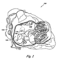
図1は開放された右心房102を有する心臓100を示す右側の側面図である。心臓100は4つの室、即ち右心房102、右心室、左心房104、及び左心室に分離される。心臓100は更に心臓の4つの室を分離する隔壁106を備える。右心房102及び左心房104を分離する、隔壁106の部分は心房中隔108と呼ばれる。左心房及び右心室を分離する、隔壁106の部分は心室中隔と呼ばれる。
FIG. 1 is a right side view showing a
図1に示すように、卵円窩110は下大静脈112の開口部の上方にして、且つ左側にて心房中隔108の下部に位置される。二次中隔(SS)116の縁114は心房中隔108の右側(即ち右心房102)内における卵円窩110の顕著な前上縁である。これは胎児の間のSS116の下縁を示す。
As shown in FIG. 1, the foveal fossa 110 is located above the opening of the
卵円窩110の通路118は、SS(肉厚な組織)116の表面及びSP(肉薄な組織)120の表面によって画定され、右心房102及び左心房104の間を延びる。ここで使用されるように、通路118はSS116及びSP120の表面によって画定され、PFOと交互に使用可能である。SS116は通路118の右縁を形成し、心房中隔108の上部をなす。従って、SS116は縁120に隣接して位置され、縁120から離間して上方且つ右側に延びる。SP120は通路118の左縁を形成し、心房中隔108の下部をなし(即ち、SS116の下方)、SS116に平行に左心房104に向かって上方且つ右側に延びる。
The
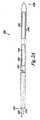
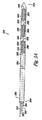
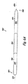
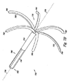
図2A乃至2Cは本発明による一実施例における閉塞器具222を示す図である。図示のように、閉塞器具222は基端部226及び末端部228を有する長尺体224を備える。実施例において、末端部228は閉塞器具222が例えばPFOの肉厚な組織(SS)及び肉薄な組織(SP)のうち少なくともいずれか一方を貫通できるように尖端として構成可能である。しかし、末端部228は鋭くなくてもよい。後述するように閉塞器具222はガイドカテーテル及び搬送カテーテルと組み合わせて使用され、PFO等の中隔欠損の組織を貫通し、組織を一体的に張引し、これにより中隔欠損を閉鎖してもよい。
FIGS. 2A-2C illustrate an
実施例において、閉塞器具222は第1の駆動部230及び第2の駆動部232を備える。第1の駆動部230及び第2の駆動部232はそれぞれ長尺体224と連動する。後述するように駆動部230,232は長尺体224上に、且つ/又は長尺体224と連動する所定の部分を備え、長尺体の所定の部分に供給される熱エネルギー及び電気エネルギーのうち少なくともいずれか一方を使用することにより制御可能である。例えば駆動部230,232は後述するように形状記憶材料の層として構成可能であり、長尺体224の一部をなす。実施例において、駆動部230,232をなす形状記憶材料の層は長尺体224に沿って延び、完全に、且つ/又は部分的に長尺体224を包囲する。付加的に、駆動部230,232はそれぞれ多数の部分を含み、これらは一体的に各駆動部230及び駆動部232のうち少なくともいずれか一方をなす。実施例において閉塞器具222は更に2つ以上の駆動部を備えてもよい。
In the embodiment, the
これに代えて、駆動部230,232は長尺体224の中心構造体(即ち、中央部分、或いは最も内側の部分)として構成されてもよい。中心構造体の周囲に1つ以上の付加的な材料(例、高分子材、生体適合性を備える材料、コーティング)が長尺体224を形成するために付加される。図2A乃至2Cは中心構造体を有する駆動部230及び232を示す図である。また、他の構造体を使用してもよい。例えば、付加的な実施例において駆動部230,232は長尺体224の一部を形成するために使用される(即ち、結合される)個別の部分として構成されてもよい。後述するように、駆動部により長尺体224は中隔欠損の組織を一体的に保持し、これにより欠損部を閉塞すべく機能する所定の形状を得られる。
Alternatively, the
図2Aはまだ駆動部230及び232が駆動されていない線形構造体における閉塞器具222を示す図である。後述するように、搬送カテーテル及び閉塞器具222を有するシステムは閉塞器具222を搬送し、中隔欠損を閉塞することに使用可能である。実施例において閉塞器具222及び搬送カテーテルのうち少なくともいずれか一方は中隔欠損の組織を貫通することに使用可能である。後述するように、線形構造体における閉塞器具222は十分に堅固であり(即ち、十分なコラム強さを有し)、これにより長尺体224はPFO等の中隔欠損の組織を貫通することができる。実施例において器具222が中隔欠損の組織を貫通すると、末端部228及び基端部226は中隔欠損組織の対向する側に位置される。
FIG. 2A shows the
図2Bは第1の駆動部230により長尺体224が第1の所定の位置234に屈曲可能であることを示す図である。図示のように、長尺体が第1の所定の位置234にある場合に末端部228は基端部226に向かって延びる。別例において、図2Aに示す屈曲していない状態にあるものと比較して、末端部228は第1の所定の位置において長尺体224の基端部226のより近傍に位置される。本実施例において、第1の駆動部は末端部228及び第2の駆動部232を基端部226及び隣接する長尺体224に対して約135°乃至225°の角度をなして配置可能である。即ち、第1の駆動部230は末端部228を図2Aに示される原位置に対して約135°乃至225°に配置可能である。図2Bに示すように、第1の駆動部は末端部228及び第2の駆動部232を図2Aに示される末端部228の原位置に対して180°の角度をなして配置する。
FIG. 2B is a diagram showing that the
実施例において、長尺体が第1の所定の位置234に位置されると閉塞器具222は例えば搬送カテーテルを使用して中隔欠損の組織を横断して引き戻される。中隔欠損の組織を通じて張引されると、長尺体224の基端部226及び末端部228の両者は中隔欠損の同じ側に位置される。別例において第1の所定の位置234に向かって移動する長尺体224の運動により末端部228は中隔欠損の組織を通じて戻ることができる。即ち、長尺体224は閉塞器具222を中隔欠損の組織を横断して戻すべく処置者によって移動される(即ち、張引される)必要がない。
In an embodiment, once the elongate body is in the first
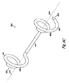
図2Cは第2の駆動部232により長尺体224が第2の所定の位置236に屈曲可能となり、これにより末端部228及び基端部226が図2Bに示す第1の所定の位置234にある場合に比較してより近傍に位置されることを示す図である。図示のように末端部228は長尺体224の基端部226に隣接する長尺体224の一部に隣接するか、接触して配置されてもよい。実施例において長尺体224は末端部228が長尺体224に接触し、図2Cに示すループ形状に保持される。これに代えて、第2の駆動部232は基端部226に隣接する長尺体224の一部の周囲にて末端部228に隣接する長尺体224の少なくとも一部を包囲することに使用されてもよい。付加的な実施例において長尺体は基端部に隣接する長尺状スリットを画定し、後述し図示するように第2の所定の位置にある場合に長尺体の末端部を受承してもよい。
In FIG. 2C, the
実施例において、第2の駆動部232により長尺体224が第2の所定の位置236に屈曲可能となる場合に、閉塞器具222は中隔欠損の組織が相互に離間して移動することを防止し、これにより組織を固定することを補助する。例えば様々な実施例において、ここで開示される閉塞器具は卵円孔開存症を閉塞させることに使用可能である。ここで使用されるように、「閉塞」とは人体の通路が閉じられること、又は少なくとも部分的に閉じられること、或いは血液及び血中の粒子のうち少なくともいずれか一方が人体の通路を通過することを防止することを示す。例えば本発明の実施例は二次中隔(SS)及び一次中隔(SP)の組織を貫通し、SS及びSPの組織により画定される卵円孔開存(PFO)の通路を閉塞する器具、システム、及び方法を含む。
In the embodiment, when the
後述するように閉塞器具222により、第1の所定の位置234及び第2の所定の位置236に至った場合に長尺体224は中隔欠損の組織に隣接して、且つ/又は対向して配置可能である。図示のように長尺体224は中隔欠損の組織がより一体的に近接するように張引することを補助することができるループ形状を有してもよい。これに代えて、長尺体224は組織に接触できるように第1の所定の位置234及び第2の所定の位置236に屈曲した後により直線的な形状を有してもよい。また、別の形状を使用してもよい。
As will be described later, the
実施例において、第1の駆動部230及び第2の駆動部232は長尺体224を屈曲させること(即ち、移動させること)、及び/又は長尺体224を所定の形状に復帰させることに使用されてもよい。後者の状況において、長尺体224は第1の所定の位置234及び第2の所定の位置236により形成されてもよい。例として、本実施例における長尺体224は図2Cに示すものと類似する。第1の駆動部230及び第2の駆動部232は長尺体224を第1の所定の位置234及び第2の所定の位置236に屈曲することを規制し、或いは保持することに使用されてもよい。駆動されると、第1の駆動部230及び第2の駆動部232は弛緩し、これにより長尺体224は所定の形状に復帰可能である。即ち、本実施例において駆動部230及び駆動部232は、長尺体224が(図2Aに示す)直線形状にある場合に駆動部230,232が駆動されて長尺体224を所定の形状に復帰させるために屈曲させるまで長尺体224を緊張状態に保持するように機能する。
In the embodiment, the
第1の駆動部230及び第2の駆動部232は更に長尺体224を屈曲させることに(即ち移動させることに)使用されてもよい。例えば、長尺体224は弛緩した緊張させていない状態において(即ち、図2Aに示す)直線形状を有する。第1の駆動部230及び第2の駆動部232はそれぞれ駆動されて、これにより長尺体224を所定の位置に屈曲させる。即ち、第1の駆動部230及び第2の駆動部232は長尺体224を移動させるものである。
The
実施例において第1の駆動部230及び第2の駆動部232は長尺体224に沿って相互に分離される。これに代えて駆動部230,232は相互に隣接してもよい。付加的に、後述するように第1の駆動部230及び第2の駆動部232はそれぞれ相互に独立して機能してもよい。従って第1の駆動部230は第2の駆動部232を駆動させることなく駆動可能であり、逆も又然りである。付加的な実施例において、2以上の駆動部が長尺体とともに使用されてもよい。例えば長尺体224は第1の駆動部230及び第2の駆動部232に関して上述したように機能する第3の駆動部、或いは更なる駆動部を含んでもよい。
In the embodiment, the
実施例において、ここで開示される駆動部に有用な形状記憶材料は、特に形状記憶ポリマーを含む。形状記憶ポリマー(SMP)は通常アクリル酸スチレン、シアン酸エステル、エポキシポリマー系をベースとした配合である。付加的に、SMPとして使用されるブロック共重合体及び共重合体セグメントはポリエーテルウレタン、ポリエステルウレタン、ポリエーテル−ポリエステル、ポリエーテル−ポリアミド、及びポリエーテルやポリエステルの柔軟なセグメントと組み合わされるその他の共重合体である。 In embodiments, shape memory materials useful for the drive disclosed herein include shape memory polymers, among others. Shape memory polymer (SMP) is usually a blend based on styrene acrylate, cyanate ester, and epoxy polymer. Additionally, block copolymers and copolymer segments used as SMP are polyether urethanes, polyester urethanes, polyether-polyesters, polyether-polyamides, and other combinations combined with flexible segments of polyethers and polyesters. It is a copolymer.
SMPを使用することにより、ここで開示される所定の形状が駆動部形成に際して付与される、即ち「記憶」される。SMPは熱的刺激により、即ち加熱されることにより堅固な状態と弾性を備えた状態との間にて変化する。変化はガラス転移温度(Tg)と呼ばれる温度にて生じる。SMPは適用の要求に応じるガラス転移温度にて形成可能である。本発明において、好適なSMPにおけるTgは40℃乃至80℃の範囲にある。カスタム設計可能な転移温度を超えると、SMPは堅固な樹脂状の状態から可撓性及び弾性を備えた状態に変移する。転移温度以下に冷却されると、SMPは再び堅固なものとなり、高比強度を備える。転移温度を超えて加熱されると、SMPは「記憶された」形状に復帰する。 By using SMP, the predetermined shape disclosed herein is imparted, or “stored”, when the drive is formed. SMP changes between a firm state and an elastic state by thermal stimulation, that is, by heating. The change occurs at a temperature called the glass transition temperature (Tg). SMP can be formed at a glass transition temperature that meets the application requirements. In the present invention, Tg in a suitable SMP is in the range of 40 ° C to 80 ° C. Beyond a custom-designable transition temperature, the SMP transitions from a rigid resinous state to a flexible and elastic state. When cooled below the transition temperature, SMP becomes solid again and has a high specific strength. When heated above the transition temperature, the SMP returns to a “memory” shape.
別例において、ここで開示される駆動部に有用な形状記憶材料は、更に電気活性ポリマー(EAP)を含む。EAPは電流に作用されるとその形状が変形する高分子材である。EAPは高い支持力を保持しつつ変形可能である。好適なEAPは誘電EAP及びイオンEAPを含む。例えば、好適なEAPはポリピロール(polypyrole)であってもよい。 In another example, a shape memory material useful for the driver disclosed herein further comprises an electroactive polymer (EAP). EAP is a polymer material that changes its shape when acted upon by an electric current. The EAP can be deformed while maintaining a high supporting force. Suitable EAPs include dielectric EAPs and ionic EAPs. For example, a suitable EAP may be polypyrrole.
再び図2A乃至2Cを参照する。長尺体224は基端部226から第1の駆動部230及び第2の駆動部232にそれぞれ延びる第1の導体素子240及び第2の導体素子242を含む。本実施例において、第1の駆動部230及び第2の駆動部232のうち少なくともいずれか一方はSMPであってもよく、第1の導体素子240及び第2の導体素子242は第1の駆動部230及び第2の駆動部232のSMPに熱的エネルギー(即ち、熱)を作用させる。実施例において第1の導体素子240及び第2の導体素子242は第1の駆動部230及び第2の駆動部232のそれぞれのSMPに隣接して、且つ/又はSMP内に配置される抵抗加熱要素244及び246を備える。例えば個別の抵抗加熱要素244及び246は各第1の駆動部230及び第2の駆動部232の長さを計測可能である。これに代えて、個別の抵抗加熱要素244及び246は1つ以上の所定の位置にて第1の駆動部230及び第2の駆動部232のそれぞれに隣接して配置されてもよい。抵抗加熱要素244及び246は第1の駆動部230及び第2の駆動部232のそれぞれの、好適には一端から他端に向かって加熱するように更に構成されてもよい。
Please refer to FIGS. 2A to 2C again. The
実施例において、導体素子は導電性金属及び合金から形成可能であり、例えば、金、チタン、医療グレードステンレス鋼(例、316L)、チタン、タンタラム、白金合金、ニオブ合金、コバルト合金、アルギン酸塩、MP35N、アルミ合金、クロム合金、バナジウム合金、記憶合金や、これらの組み合わせが挙げられる。付加的に、長尺体224は医療グレ―ド高分子材及び共重合体のうち少なくともいずれか一方から形成可能であり、例えば、ポリプロピレン、ポリスチレン、ポリウレタン、ポリ塩化ビニル、ポリエチレン、ポリエーテル−エーテル−ケトン、ポリエーテルイミド、ポリアミド、ポリカーボネート、生分解性を備えた材料、及びこれらの組み合わせが挙げられる。その他の医療グレード高分子材、金属、合金が上記応用に使用されてもよい。
In an embodiment, the conductive element can be formed from a conductive metal and alloy, such as gold, titanium, medical grade stainless steel (eg, 316L), titanium, tantalum, platinum alloy, niobium alloy, cobalt alloy, alginate, Examples thereof include MP35N, aluminum alloy, chromium alloy, vanadium alloy, memory alloy, and combinations thereof. In addition, the
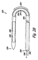
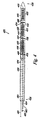
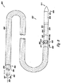
図3A乃至3Cは本発明による付加的な実施例における閉塞器具322を示す図である。図示のように閉塞器具322は基端部326及び末端部328を有する長尺体324を備える。閉塞器具322は更に第1の駆動部330、第2の駆動部332、及び第3の駆動部348を備える。第1の駆動部330、第2の駆動部332、及び第3の駆動部348はそれぞれ長尺体324と協動する。付加的に、実施例において、閉塞器具322は3つ以上の駆動部を備えてもよい。
FIGS. 3A-3C illustrate an
後述するように、駆動部330,332,348は長尺体324を少なくとも部分的に包囲する層として、長尺体324のコア構造体として、及び/又は長尺体324の完成した部分を形成する個別の部分又は区分として設けられる。本実施例において、駆動部330,332,348は長尺体324を少なくとも部分的に包囲する層として設けられる。付加的に、上述したように第1の駆動部330、第2の駆動部332、及び第3の駆動部348は長尺体324を屈曲(即ち、移動)させ、且つ/又は長尺体324を所定の形状に復帰させる。
As will be described later, the
実施例において、1つ以上の第1の駆動部330、第2の駆動部332、及び第3の駆動部348は上述したように特にEAPから形成される。EAPから駆動部を形成することに加えて、長尺体324は基端部326から第1の駆動部330、第2の駆動部332、及び第3の駆動部348のそれぞれに向かって延びる第1のリード線350、第2のリード線352、及び第3のリード線354を含んでもよい。リード線350,352,354は第1の駆動部330、第2の駆動部332、及び第3の駆動部348のEAPに電流を供給することに使用可能である。
In the embodiment, the one or more first driving
実施例において、リード線350,352,354はそれぞれ、各第1の駆動部330、第2の駆動部332、及び第3の駆動部348のEAPに電流を供給することに使用可能な電極356(即ち、陰極)に連結可能である。第2の電極358(即ち、陽極)は搬送装置322と組み合わせて使用される長尺体324の表面及び搬送カテーテルのうち少なくともいずれか一方に配置されてもよい。後述するように、電極極性は反転可能である。
In the embodiment, the
図3A乃至3Cに示すように、各電極356は対応する第1の駆動部330、第2の駆動部332、及び第3の駆動部348に隣接して配置される。実施例において、電極356は対応する駆動部に隣接して設けられ、これにより電流が駆動部のEAPを通じて第2の電極358に流れる。実施例において、電極356は大きな表面積を備え、EAPを通過する電流密度を好適に保持するように構成可能である。実施例において、各電極356は駆動部330,332,348と協動し、これらを制御してもよい。
As shown in FIGS. 3A to 3C, each
実施例において、電極356は各駆動部330,332,348の下方に配置され、且つ/又は隣接するリング、部分的なリング、電極であってもよい。リングや部分的なリングの形状において、後述するように電極356は駆動部330,332,348及び長尺体324のうち少なくともいずれか一方を所定の形状に屈曲させることができるように可撓性を備える。例えば、電極356は長尺体324と各駆動部330,332,348との間に少なくとも部分的に設けられる金属及び合金(例えば、金、チタン、医療グレードステンレス鋼(例、316L)、チタン、タンタラム、白金合金、ニオブ合金、コバルト合金、アルギン酸塩、MP35N、アルミ合金、クロム合金、バナジウム合金、或いはこれらの組み合わせ)のうち少なくともいずれか一方からなる導電性膜であってもよい。
In an embodiment, the
付加的な実施例において、電極356は駆動部330,332,348を通過して、且つ/又は駆動部330,332,348に隣接して延びる一列の又は一連の導体として構成されてもよい。別例において、一列の又は一連の導体は長尺体324に沿って螺旋状に延びてもよい。これに代えて、一列の又は一連の導体は長尺体324に沿って線状に延びてもよい。
In additional embodiments, the
後述するように、第2の電極358(即ち、陽極)は長尺体324の表面上に位置される。実施例において、第2の電極358の少なくとも1つの表面は長尺体324の周囲の環境に暴露される。第2の電極358は多数の異なる所定の形状を有する。例えば第2の電極358は環状のリング及び半環状のリングのうち少なくともいずれか一方として構成される。その他の形状も使用可能である。本発明の実施例において電極は2つに限定されるものではない。付加的に、電極は閉塞器具322及び長尺体324のうち少なくともいずれか一方とは独立したシステムの部分であってもよい。
As will be described later, the second electrode 358 (that is, the anode) is positioned on the surface of the
実施例において、1つ以上の第2の電極358は閉塞器具322とともに使用可能である。例えば第2の電極358の1つはリード線350,352,354と連結される各電極356の陽極として使用可能である。即ち、第2の電極358のうち1つはリード線350,352,354の各個別の電極356を通過する電流を流すための電極として使用される。別例において、1つ以上の第2の電極358が長尺体324とともに使用されてもよい。例えば、図3A乃至3Cに示すように3つの第2の電極358が長尺体324とともに使用可能である。第2の電極358は駆動部330,332,348に隣接して配置される。3つの第2の電極358はそれぞれ個別のリード線に接続されてもよい。これに代えて、3つの第2の電極358は1つの共通のリード線360に共通して接続されてもよい。
In an embodiment, one or more
図示のように駆動部330,332,348の組み合わせは長尺体324を屈曲させ、又は屈曲させる要因となるべく使用されてもよい。例えば、第1の駆動部330及び第2の駆動部332の組み合わせが長尺体324を第1の所定の位置334に屈曲させることに使用されてもよい。図示のように長尺体が第1の所定の位置334にある場合に末端部328は基端部326に向かって延びる。本実施例において、第1の駆動部330及び第2の駆動部332は基端部326及び隣接する長尺体324に対して約135°乃至225°の角度をなすように末端部328及び第2の駆動部332を配置可能である。
As shown in the figure, the combination of the
付加的な実施例において、第3の駆動部356により長尺体324は第2の所定の位置336に屈曲される。位置336において、末端部228及び基端部226は第1の所定の位置334にある場合と比較してより近接して位置される。図示のように末端部328は長尺体324の基端部326に隣接する長尺体324の一部に隣接するか接触して設けられる。後述するように、駆動部330,332,356は長尺体324を3つの個別の所定の位置(即ち、各第1の所定の位置、第2の所定の位置、及び第3の所定の位置)に屈曲させることに使用可能である。
In an additional embodiment, the
実施例において、図3Cに示すように長尺体324は、末端部328を長尺体324に接触させてループ形状に保持される。例えば本実施例において、長尺体324は基端部326に隣接する長尺状スリット362又は開口部を画定し、長尺体324が第2の所定の位置336にある場合に長尺体324の末端部328を受承する。実施例において末端部328は第2の駆動部332により作用される圧力により、長尺状スリット362内に摺動する。これに代えて、スリット362の周囲は長尺体324の末端部328を受承するために十分にスリット362を開放することに使用可能なSMPやEAPを備えてもよい。
In the embodiment, as shown in FIG. 3C, the
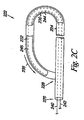
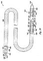
図4は本発明による付加的な実施例における閉塞器具422を示す図である。図示のように、閉塞器具422は、基端部426、末端部428、第1の駆動部430、第2の駆動部432、及び第3の駆動部448を備える長尺体424を含む。閉塞器具422は電極456(即ち、陰極)にそれぞれ連結されるリード線450,452,454を更に備え、これらは上述したように各第1の駆動部430、第2の駆動部432、及び第3の駆動部448のEAPに電流を供給することに使用可能である。
FIG. 4 shows a
図示のように、長尺体424は基端部426から少なくとも第1の駆動部430、第2の駆動部432、及び第3の駆動部448に延びる管腔464を更に備える。実施例において、管腔464は長尺体428内の中心に、或いは偏心して位置される。管腔464は変位可能なリード線466を受承し、通過させるために十分な大きさの周囲を有する。実施例において、変位可能なリード線464は管腔462を通過して延び、管腔462内において移動自在であり、これにより電極456を使用して電流が第1の駆動部430、第2の駆動部432、及び第3の駆動部448のEAPを通過して流される。
As shown, the elongate body 424 further includes a
実施例において、変位可能なリード線466は絶縁シースを伴い、或いは伴わずに電気的に導電性を備えた材料(例、金属や合金)から形成可能である。変位可能なリード線466は管腔464を画定する表面と能動的に物理的に接触するように構成される末端部468を更に備えてもよい。例えば変位可能なリード線466は末端部468に隣接する所定の屈曲部やたわみ部を有し、これにより管腔464の表面と接触可能である。
In embodiments, the
実施例において第2の電極458は管腔464を画定する少なくとも1つの部分の表面を備える。変位可能なリード線466は管腔464内を移動自在であり、これによりリード線466の末端部468及び末端部468に隣接するリード線466の部分のうち少なくともいずれか一方は管腔464を画定することを補助する第2の電極458の部分と接触する。図示のように、第2の電極458は更に長尺体424の外側表面の一部を画定する。
In an embodiment, the
実施例において変位可能なリード線466は管腔464内を移動自在であり、これにより長尺体428と協動する第2の電極458はそれぞれ個別に電気的に接触する。実施例において管腔462の表面の一部を画定する第2の電極458の表面はリード線466が解放可能に着座する切り欠きを備える。実施例において、基端部に隣接する変位可能なリード線466上のマークが使用可能であり、これにより使用者はいずれの第2の電極458が変位可能なリード線466と電気的に接触しているかを特定可能である。
In an embodiment, the
実施例において、変位可能なリード線466は管腔464内において所望の第2の電極458と電気的に接触させるべく移動自在である。電流が好適な第2の電極458及び電極456を使用して1つ以上の第1の駆動部430、第2の駆動部432、第3の駆動部448を横断して作用され、これにより上述したように器具422を第1の所定の位置及び第2の所定の位置に屈曲させる。
In an embodiment, the
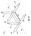
図5A乃至5Cは本発明による付加的な実施例における閉塞器具522を示す図である。実施例において、閉塞器具522は2つ以上のワイヤ570を備えた長尺体524を有する。ワイヤ570は長尺体524の中央部572に沿って一体的に結束される。ワイヤ570の結束はワイヤ570を一体的に捻ることを含む。これに代えて、ワイヤ570の結束は長尺体524の中央部572を得るべくワイヤ570を一体的に編み込み、且つ/又は編み組みすることを含んでもよい。ワイヤ570は図示のように線形であってもよい。更に、中央部572におけるワイヤ570は(例えばレーザー溶接により)一体的に融合されてもよい。
FIGS. 5A-5C illustrate an
閉塞器具522は更に第1の駆動部530及び第2の駆動部532を備える。実施例において、第1の駆動部530及び第2の駆動部532は長尺体524の中央部572から延びる1本以上のワイヤ570からなる所定の部分574により形成されてもよい。第1の駆動部530及び第2の駆動部532により、2本以上の各ワイヤ570からなる所定の部分574は長尺体524の中央部572を通過して延びる共通軸576から径方向に延びる。従って、例えば第1の駆動部530により末端部528に隣接する2本以上の各ワイヤ570からなる所定の部分574は共通軸576から径方向に延びる。同様に、第2の駆動部532により基端部526に隣接する2本以上の各ワイヤ570からなる所定の部分574は共通軸574から径方向に延びる。図5B及び5Cはこれらの実施例を示す図である。
The
使用時において閉塞器具522の末端部528はまず中隔欠損の組織を横断して挿入され、これにより基端部526及び末端部528は中隔欠損の対向する側に位置される。第1の駆動部530は末端部528に隣接するワイヤ570の所定の部分574を径方向に広げることに使用可能である。同様に、第2の駆動部532は基端部526に隣接するワイヤ570の所定の部分574を径方向に広げることに使用可能である。ワイヤ570の所定の部分574が径方向に広がると、これらは中隔欠損の組織が一体的により近接するように接触し、張引し、これにより中隔欠損部を閉鎖することを補助する。
In use, the
実施例において、第1の駆動部530及び第2の駆動部532を形成する所定の部分572は上述したようにワイヤ570上のSMP及びEMPのうち少なくともいずれか一方からなるコーティングであってもよい。これに代えて、第1の駆動部530及び第2の駆動部532を形成する所定の部分574は上述したように導電性を備えた材料によりコーティングされたSMP及びEMPのうち少なくともいずれか一方からなるコア部であってもよい。実施例において、ワイヤ570自体が電極として使用可能であり、熱的エネルギー(即ち、熱)及び電流のうち少なくともいずれか一方を供給し、これにより図5B,5Cに示すように駆動部530,532の所定の部分574を共通軸から径方向に延ばす。
In the embodiment, the
実施例において、第1の駆動部530及び第2の駆動部532をなすワイヤ570は、相互に隣接して設けられる。ワイヤ570(例、1本以上)の第1の所定の群は第1の電極(例、陰極)として使用可能であり、ワイヤ570の第2の所定の群は第2の電極(例、陽極)として使用可能である。駆動部530及び532はEMPのコーティングを含む場合に、電流は電極をなすワイヤ570間を流れこれによりEMPは形状を変化させる。これに代えて、駆動部530及び532がSMPのコーティングを含む場合に、ワイヤ570はSMPを加熱すべく電流が通過して流れる導電性を備えたループをなし、これにより上述したようにワイヤ570の形状を変化させてもよい。
In the embodiment, the
これに代えて、ワイヤ570は第1の電極(陰極及び陽極のいずれか)として使用可能であり、第2の電極はワイヤ570の末端側の部位に設けられてもよい。例えば、反対側の電極は一時的に患者の肌上に設けられる(例、皮膚及び皮下のうち少なくともいずれか一方)。
Alternatively, the
付加的な実施例において、個別の導電要素(例、絶縁ワイヤ)は長尺体524を通過してコア又はSMPのコーティングを備える駆動部530又は532に隣接した、且つ/又は駆動部530又は532内に設けられる抵抗加熱要素に延びてもよい。これに代えて、個別のリード線が長尺体524を通過して延び、コア又はSMPのコーティングを備える駆動部530又は532に隣接した、且つ/又は駆動部530又は532内に設けられる抵抗加熱要素に第1の電極(例、陰極)となり、第2の電極(例、陽極)が閉塞器具522から離間して設けられてもよい。これに代えて、駆動部530及び532は電流がEMPを通過するように第1の電極及び第2の電極として機能してもよい。その他の形状も使用可能である。
In additional embodiments, individual conductive elements (eg, insulated wires) pass through the
別例において、ワイヤ570は第1の所定の位置及び第2の所定の位置を有する形状記憶ポリマー及び/又は形状記憶金属等の記憶材料から形成されてもよい。閉塞器具522は搬送に適した形状に弾性的に変形可能であり、配置時にワイヤをなす記憶材料が器具522を所定の位置に移動させる。これに代えて、上述したように加熱要素が記憶金属を転移温度に加熱することに使用され、これにより器具522を駆動部530,532内にて移動させてもよい。形状記憶金属の例として、ニチノール、チタン−パラジウム−ニッケル、ニッケル−チタン−銅、金−カドミウム、鉄−亜鉛−銅−アルミ、チタン−ニオブ−アルミ、ハフニウム−チタン−ニッケル、鉄−マンガン−ケイ素、ニッケル−チタン、ニッケル−鉄−亜鉛−アルミ、銅−アルミ−鉄、チタン−ニオブ、ジルコニウム−銅−亜鉛、ニッケル−ジルコニウム−チタン等の記憶金属が挙げられるが、これらに限定されるものではない。その他の金属及び合金も使用可能である。
In another example, the
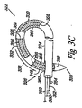
図6A乃至6Cは本発明による付加的な実施例における閉塞器具622を示す図である。実施例において、閉塞器具622は第1の駆動部630及び第2の駆動部632を備える長尺体624を有する。上述したようにリード線及び接続部のうち少なくともいずれか一方を備える第1の駆動部630及び第2の駆動部632が形成される。
FIGS. 6A-6C illustrate an
実施例において、第1の駆動部630及び第2の駆動部632は長尺体624の末端部628に隣接する第1の所定の区分678及び長尺体624の基端部626に隣接する第2の所定の区分680を共通軸676から径方向に延ばすように構成される。図6Cに示すように第1の所定の区分678及び第2の所定の区分680は共通軸676から、且つ/又は共通軸676の周囲にて同心682に、又は偏心684して延びる。
In the embodiment, the
実施例において所定の区分678,680の形状により閉塞器具622は中隔欠損の組織を横断して配置された場合に中隔欠損の組織を一体的に保持し、これにより欠損を閉塞することができる。本実施例において、所定の区分678,680により長尺体624は螺旋状に屈曲可能である。付加的に、所定の区分678,680は平面又は非平面にて径方向に延びる。非平面形状の例として、円錐形、半球状、或いはその他の非平面形状が挙げられる。
In an embodiment, the shape of the
長尺体624の所定の区分678,680はその他の形状も可能である。例えば、その他の形状は多角形、螺旋形、渦巻き状、三日月状、湾曲した形状、鞍形状、及び不規則な形状を含む。様々な実施例においてこれらの所定の形状は中隔欠損の組織を係合させることを補助する表面及び構造体を含む。ここで使用されるように、中隔欠損の組織の係合は、通路の組織の貫通、トラップ、圧搾、挟持、把持、把握、フック、隣接、捕獲、及び押圧を含み、これにより組織を固定し中隔欠損を閉塞する。
The
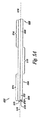
図7A乃至7Cは本発明による付加的な実施例における閉塞器具722を示す図である。実施例において、閉塞器具722は第1の駆動部730及び第2の駆動部732を備える長尺体724を有する。上述したようにリード線及び接続部のうち少なくともいずれか一方を備える第1の駆動部730及び第2の駆動部732が形成される。
FIGS. 7A-7C illustrate an
実施例において、第1の駆動部730及び第2の駆動部732は長尺体724の末端部728に隣接する第1の所定の区分778及び長尺体724の基端部726に隣接する第2の所定の区分780を共通軸776から径方向に延ばすように構成される。本実施例において、所定の区分778,780は共通軸776から径方向に延びる区分782を備える。図7B,7Cに示すように、例えば区分782は第1の所定の位置及び第2の所定の位置にて共通軸776から対称に径方向に広がる。区分782はここで開示される実施例による第1の駆動部730及び第2の駆動部732により駆動される。実施例において区分782は長尺体724により形成されるが、長尺体724を区分782の所望の形状に切断、且つ/又は分割することにより形成される。第1の所定の位置及び第2の所定の位置のその他の形状も使用可能である。
In the embodiment, the
実施例において、閉塞器具722は形状記憶合金から形成される第1の駆動部730及び第2の駆動部732を備える長尺体724を有し、第1の所定の区分778及び第2の所定の区分780は共通軸776から径方向に延びる。例えば閉塞器具722は閉塞器具を図7Aに示すような位置に保持するシースを備えてもよい。図7Bに示すようにシースが取り払われると末端部728が暴露され、第1の所定の区分778上の区分782は共通軸776から径方向に延びる。更に、図7Cに示すようにシースが完全に取り払われると第2の所定の区分778上の区分783も共通軸778から径方向に延びる。
In an embodiment, the
図8は本発明の実施例におけるガイドカテーテル886と、搬送カテーテル888と、閉塞器具822とを備えるシステム884を示す。搬送カテーテル888は第1の端部890と第2の端部892とを含む。ガイドカテーテル886は基端部894及び末端部896を備え、端部894,896を通過して延びる管腔898を備える。管腔898は搬送カテーテル888及び閉塞器具822がガイドカテーテル886を通過して移動できるような寸法に形成される。ガイドカテーテル886は更に管腔898内に配置された場合に搬送カテーテル888を側方向から支持する。この側方向からの支持により、長手方向の圧力が第1の端部890に作用され、閉塞器具822を前進させるべく搬送カテーテル888を通じて伝達される。
FIG. 8 shows a
実施例において、搬送カテーテル888は内部に少なくとも部分的に配置され、ガイドカテーテル886の管腔898内を長手方向に移動する。実施例においてガイドカテーテル886は所定の形状を有し、これにより搬送カテーテル888及び閉塞器具822のうち少なくともいずれか一方はガイドカテーテル886の末端部896の、中隔欠損の組織に対する好適な位置にて延びる。図示のように搬送カテーテル888の第1の端部890はガイドカテーテル886の基端部894の上方を延び、これにより処置者は後述するようにシステム884を操作可能となる。後述するように搬送カテーテル888の所定の形状は中隔欠損の領域の物理的形状に左右される。
In an embodiment,
後述するように閉塞器具822は閉塞器具822の形成に使用される形状及び材料次第により、様々な方法にて移植される。例えば閉塞器具822の長尺体824が駆動部830及び832にSMPを使用する場合にここで開示されるように長尺体824は導体素子840及び842、並びに抵抗加熱要素844及び846を備える。
As described below, the
実施例において閉塞器具822は搬送カテーテル888に解放可能に連結される。例えばシステム884はガイドカテーテル888及び連結器具822を解放可能に連結させる連結スリーブ801を備える。実施例において連結スリーブ801はガイドカテーテル886に連結され、且つ/又は末端部896から延び、基端部826及び長尺体824の少なくとも一部が陥入するソケット803を備える。実施例において連結スリーブ801は接着剤を使用してガイドカテーテル888に固定される。これに代えて、連結スリーブ801はガイドカテーテル888をなす材料と同一の材料の延長部であってもよい。
In an embodiment, the
実施例において連結スリーブ801は閉塞器具822の周囲を解放可能に圧縮し、閉塞器具822をガイドカテーテル888に固定することに使用されてもよい。連結スリーブ801は例えばSMP及びEAPのうち少なくともいずれか一方、或いはその他の材料により形成され、これによりソケットは寸法を大きくできる。従って、連結器具822は搬送カテーテル888から解放自在である。SMPを加熱するために、且つ/又はEAPを横断して搬送するために電流がリード線805により流される。
In embodiments, the connecting
実施例において搬送カテーテル888は第1の導線807及び第2の導線809を更に備える。実施例において導線807,809により、電流は長尺体824の導体素子840,842及び抵抗加熱要素844,846に流れる。実施例において第1の導線807及び第2の導線809は導体素子840,842に解放可能に連結される末端部811を備える。実施例において導体素子840,842は導線807,809の末端部811に解放可能に係合するような形状に形成される端部813を備える。例えば導体素子840,842の端部813はソケットとして構成される導線807,809の末端部811に解放可能に係合する球状(即ち、ボール型)を有してもよい(ボール及びソケットの設計)。続いて電流が長尺体824の抵抗加熱要素844,846に導線807,809を通じて流される。実施例においてボール及びソケットの設計により、連結スリーブ801が閉塞器具822を解放することに使用される場合に導線807,809及び導体素子840,842は相互に解放される。
In the embodiment, the
実施例において連結スリーブ801は搬送カテーテル888及び閉塞器具822の連結を保持するために十分な圧縮力を閉塞器具822の長尺体824の少なくとも一部の周囲に対して、カテーテル888及び器具822を解放させるまで作用させる。実施例において圧縮力は、カテーテル888及び器具822の連結を保持するために十分であり、例えば、張引力が搬送カテーテル888を通じて器具822に作用される。付加的な実施例において、ソケット803に陥入するカテーテル888及び器具822の表面は2つの構造体を連結させることを補助する1つ以上の表面を備えてもよい。例えばソケット803の表面は器具822の長尺体824の対応するチャネルに解放可能に陥入する頭部を備える。その他の構造体及び形状のうち少なくともいずれか一方が使用可能である。
In an embodiment, the connecting
後述するように本実施例は図8に示す閉塞器具822に限定されるものではない。別例において、後述する閉塞器具822が搬送カテーテル888と組み合わせて使用可能である。
As will be described later, the present embodiment is not limited to the
放射線不透過性のマーカーが閉塞器具822、ガイドカテーテル886、及び/又は搬送カテーテル888上に設けられてもよい。放射線不透過性のマーカーは閉塞器具822、ガイドカテーテル886、及び/又は搬送カテーテル888の所定の部分と連動する顕著な形状を有する。これにより処置者は患者の体内においてカテーテル886,888及び/又は閉塞器具822のよりよい位置を得られる。放射線不透過性マーカーは金、硫酸バリウム、三酸化ビスマス、炭酸ビスマス、タングステン、タンタラム等を含む。
Radiopaque markers may be provided on the
後述するように、ガイドカテーテル886、搬送カテーテル888、及び閉塞器具822の長尺体824は血管系を通過して移動される場合に屈曲に抵抗するために十分な壁強度を有する可撓性を備えた材料から形成される。実施例において、好適な可撓性を備えた材料は、ポリプロピレン、ポリスチレン、ポリウレタン、ポリ塩化ビニル、ポリエチレン、ポリエーテル−エーテルケトン、ポリエーテルイミド、ポリアミド、ポリカーボネート、生態分解性を備えた材料、及びこれらの組み合わせ等の医療グレード高分子材及び共重合体のうち少なくともいずれか一方を含むがこれらに限定されるものではない。上記応用のためのその他の医療グレード高分子材、金属、合金も使用可能である。
As described below, the
付加的に、導線807,809は金属や合金であってもよい。これらの金属及び合金の例として、上述したものが挙げられるが、それらに限定されるものではない。その他の金属及び合金も使用可能である。
In addition, the
本実施例による閉塞器具822を移植するために、ガイドカテーテル886は例えば上大静脈や下大静脈を通過して前進され、末端部896を心臓の右心房に位置される。ガイドカテーテル886を位置させるその他の進入地点及び進入部位が使用可能である。続いて閉塞器具822及び搬送カテーテル888がガイドカテーテル886の管腔898を通過して前進され、右心房に位置される。搬送カテーテル888の第2の端部892及び閉塞器具822の末端部828のうち少なくともいずれか一方がPFOのSS及びSP等の中隔欠損の組織に隣接して位置される。
To implant the
閉塞器具822の長尺体824と共に末端部828は中隔欠損の組織を通じて移動され、末端部828及び基端部826はそれぞれ組織の反対側に配置される。実施例において長尺体824は中隔欠損の組織を貫通する先端を有する先端部811を備える。実施例において中隔欠損の組織は、長尺体824を通じて末端部826から末端部828に押圧力を作用させることにより貫通される。
The
本実施例において閉塞器具822は組織を横断して前進され、中隔欠損を横断するように第1の駆動部830及び第2の駆動部832を配置する。長尺体824の第1の駆動部830は上述したように駆動され、先端部811及び長尺体824の第1の所定の部分を中隔欠損に戻すように配向する。続いて先端部811及び末端部828は中隔欠損の組織を通じて戻され、これにより第2の駆動部832の少なくとも一部を第1の駆動部830に対して中隔欠損の反対側に位置させる。実施例において、これらは搬送カテーテル888を使用して閉塞器具822を張引することにより実施される。
In this example, the
続いてここで開示されるように第2の駆動部が長尺体上にて駆動され、長尺体の第2の所定の部分がPFOに配向される。長尺体824の第1の所定の部分及び第2の所定の部分は長尺体をPFOに固定すべく機能する。実施例において長尺体824は上述したように長尺体824を中隔欠損の組織の反対側に固定することに使用されるループ構造体をなす。これに代えて長尺体824は径方向に延びる複数の形状(例、螺旋状やその他の外形)をなしてもよく、これらの形状は中隔欠損の対抗する組織の面(即ち、第1の側及び第2の側)に相互に向かって延びる。
Subsequently, as disclosed herein, the second drive unit is driven on the elongated body, and the second predetermined portion of the elongated body is oriented to the PFO. The first predetermined portion and the second predetermined portion of the
後述するようにシステム884の上記記載は図3A乃至3Cに示す閉塞器具と組み合わせて応用可能であり、システム884は要求に応じて付加的なリード線や駆動部を備えてもよい。
As described below, the above description of
図9は本発明の実施例における、ガイドカテーテル986と、搬送カテーテル988と、閉塞器具922とを備えるシステム984を示す図である。閉塞器具922は図4に示す閉塞器具に類似する。上述したように搬送カテーテル988は第1の端部990及び第2の端部992を備え、ガイドカテーテル986は基端部994及び末端部996を備え、端部994,996を通過して延びる管腔998を備える。
FIG. 9 illustrates a
本実施例において閉塞器具922は基端部926及び末端部928を備える長尺体924、並びに第1の駆動部930、第2の駆動部932、及び第3の駆動部948を備える。閉塞器具922はここで開示されるようにそれぞれが電極956(例、陰極)に接続されるリード線950,952,954を更に備え、これらは第1の駆動部930、第2の駆動部932、及び第3の駆動部948のそれぞれのEAPに電流を供給する。
In this embodiment, the
上述したように、長尺体924は基端部926から少なくとも第1の駆動部930、第2の駆動部932、及び第3の駆動部948に延びる管腔を更に備える。システム984は上述したように管腔を通過して延び、管腔内を移動自在にして、変位可能なリード線966を更に備え、これにより電極956を使用して第1の駆動部930、第2の駆動部932、及び第3の駆動部948のEAPに電流を流す。閉塞器具922は上述したように第2の電極958を更に備え、変位可能なリード線966は管腔内を移動自在であり、これにより末端部及び端部に隣接するリード線966の一部のうち少なくともいずれか一方を第2の電極に接触させる。
As described above, the
本実施例において搬送カテーテル988は管腔921を更に備え、管腔921は第1の端部990及び第2の端部922を通過して延び、長尺体924の管腔と連結する。変位可能なリード線966はここで開示されるように管腔921を通過して長尺体924の管腔に延びて移動し、第2の電極958と電気的に接触する。
In this example, the
実施例において閉塞器具922は搬送カテーテル988に解放可能に連結される。例えばシステム984はここで開示されるようにソケット903及びリード線905を備える連結スリーブ901を含む。連結スリーブ901はガイドカテーテル988及び連結器具922を解放可能に連結する。
In an embodiment, the
実施例において搬送カテーテル988は第1の導線907と、第2の導線909と、第3の導線923とを更に備える。実施例において導線907,909,923により電流は長尺体924中のリード線950,952,954に流れる。実施例においてリード線950,952,954は導線907,909,923に解放可能に連結される末端部911を備える。実施例において導線907,909,923は導線907,909,923の末端部811を解放自在に係合するような形状に形成される端部913を備える。実施例は上述したボール及びソケットの設計を含む。電流は続いて導線907,909,923を通じて電極956に供給される。
In the embodiment, the
放射線不透過性のマーカーが上述したように閉塞器具922、ガイドカテーテル986、及び/又は搬送カテーテル988上に設けられてもよい。付加的に、ガイドカテーテル986、搬送カテーテル988、及び閉塞器具922の長尺体924は上述したように血管系を通過して移動される場合に屈曲に抵抗するために十分な壁強度を有する可撓性を備えた材料から形成されてもよい。付加的に、導線907,909,923は金属や合金であってもよい。これらの金属及び合金の例として、上述したものが挙げられるが、それらに限定されるものではない。その他の金属及び合金も使用可能である。
Radiopaque markers may be provided on the
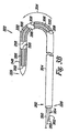
図10は本発明の実施例における、ガイドカテーテル1086と、搬送カテーテル1088と、閉塞器具1022とを備えるシステム1084を示す。本実施例において、閉塞器具1022は図6A乃至6Cにて上述したものである。しかし、システム1084の記載は図5A乃至5C及び/又は図7A乃至7Cに示すもののうちいずれかにおいて上述した閉塞器具と組み合わせて適用可能である。
FIG. 10 illustrates a
上述したように、搬送カテーテル1088は第1の端部1090及び第2の端部1092を備え、ガイドカテーテル1086は基端部1094及び末端部1096を備え、端部1094,1096を通過して延びる管腔1098を備える。図示のように搬送カテーテル1088及び閉塞器具1022はガイドカテーテル1086の部分1027内に収容される。実施例においてガイドカテーテル1086の末端部1096は中隔欠損の組織を貫通するために十分鋭利な尖端部を備える。末端部1096も閉塞器具1022の中隔欠損を横断した搬送時に閉塞器具1022を通過させる開口部1029を画定する。実施例において開口部1029は搬送カテーテル1088を通じて押圧力が作用される場合にガイドカテーテル1086から閉塞器具1022が移動できるように拡張されてもよい。
As described above, the
本実施例において閉塞器具1022は基端部1026及び末端部1028を備える長尺体1024、並びに第1の駆動部1030及び第2の駆動部1032を備える。閉塞器具1022はそれぞれが第1の駆動部1030及び第2の駆動部1032に解放可能に連結されるリード線1050,1052を更に備える。図示のようにリード線1050,1052は長尺体1024の中間領域にて駆動部1030,1032に解放可能に連結される。実施例においてこれらの構成により、第1の駆動部1030及び第2の駆動部1032はここで開示されるようにリード線1050,1052に対する解放可能な連結を妨害することなく径方向に拡張(即ち、移動)可能である。
In this embodiment, the
実施例において上述したように閉塞器具1022は搬送カテーテル1088に解放可能に連結される。例えばシステム1084は上述したようにソケット1003及びリード線1005を備える連結スリーブ1001を備える。連結スリーブ1001はガイドカテーテル1088及び連結器具1022を解放可能に連結する。
As described above in the embodiment, the
実施例において搬送カテーテル1088は第1の導線1007及び第2の導線1009を更に備え、これらにより電流が長尺体1024のリード線1050,1052に流れる。実施例において、リード線1050,1052は導線1007,1009に解放可能に連結される末端部1011を含む。実施例において導線1007,1009は導線1007,1009の末端部1011に解放可能に係合するような形状に形成される端部1013を備える。実施例は上述したボール及びソケットの設計を含む。
In an embodiment, the
上述したように放射線不透過性を備えたマーカーが閉塞器具1022、ガイドカテーテル1086、及び/又は搬送カテーテル1088上に設けられてもよい。付加的に、ガイドカテーテル1086、搬送カテーテル1088、及び閉塞器具1022の長尺体1024は上述したように血管系を通過して移動される場合に屈曲に抵抗するために十分な壁強度を有する可撓性を備えた材料から形成されてもよい。付加的に導線1007,1009は金属や合金であってもよい。これらの金属及び合金の例として、上述したものが挙げられるが、それらに限定されるものではない。その他の金属及び合金も使用可能である。
As noted above, radiopaque markers may be provided on the
別例において、上述した長尺体及び駆動部のうち少なくともいずれか一方は1つ以上の治療薬を含んでもよい。実施例において1つ以上の治療薬は長尺状部材及び駆動部のうち少なくともいずれか一方を形成することに使用される材料に統合され、且つ/又は長尺体及び駆動部のうち少なくともいずれか一方の表面上にコーティングされてもよい。1つ以上の治療薬はセットされると、長尺体及び駆動部のうち少なくともいずれか一方に到達し、且つ/又は長尺体及び駆動部のうち少なくともいずれか一方から解放される。治療薬は内皮化(endothelialization)を促進、且つ/又は加速するために含まれる。 In another example, at least one of the elongated body and the driving unit described above may include one or more therapeutic agents. In an embodiment, the one or more therapeutic agents are integrated into the material used to form at least one of the elongate member and the drive and / or at least one of the elongate body and the drive. It may be coated on one surface. When one or more therapeutic agents are set, they reach at least one of the long body and the driving unit and / or are released from at least one of the long body and the driving unit. The therapeutic agent is included to promote and / or accelerate endothelialization.
治療薬の例として非ジェネリックの薬剤、生体分子、微粒子や、細胞等の薬学的に受け入れられる薬剤が挙げられるが、これらに限定されるものではない。非ジェネリックの治療薬は後述するものを含む。ヘパリン、ヘパリン派生物、(ミセルプロスタグランジンE1を含む)プロスタグランジン、ウロキナーゼ、及びPPack(デキストロフェニルアラニンプロリンアルギニンクロロメチルケトン(dextrophyenylalanine proline arginine chloromethylketone))等の抗血栓剤。エノキサプリン(enoxaprin )、アンジオペンプティン(angiopenptin)、シロリムス(ラパマイシン)、タクロリムス、平滑筋細胞の増殖を阻害すべく機能するエベロリムスモノクローナル抗体(everolimus monoclonal antibodies)、ヒルジン、及びアセチルサリチル酸等の抗増殖剤(anti-proliferative agents )。デキサメタゾン、ロシグリタゾン、プレドニゾロン(prednisolone)、コルチコステロン、ブデソニド、エストロゲン、エストラジオール、スルファサラジン、アセチルサリチル酸、ミコフェノール酸、メサラミン等の抗炎症薬。パクリタキセル、エポシロン(epothilone)、クラドリビン(cladribine)、フルオロウラシル(5−FU)、メトトレキサート、ドキソルビシン、ダウノルビシン、シクロスポリン、シスプラチン、ビンブラスチン、ビンクリスチン、エポシロン(epothilones )、エンドスタチン(endostatin)、トラピジル(trapidil)、ハロフジノン(halofuginone)、及びアンギオスタチン(angiostatin )等の抗がん剤又は抗増殖剤(anti-proliferative agents )又は有糸分裂阻害薬(anti-mitotic agents )。 Examples of therapeutic agents include, but are not limited to, non-generic drugs, biomolecules, microparticles, and pharmaceutically acceptable drugs such as cells. Non-generic therapeutic agents include those described below. Antithrombotic agents such as heparin, heparin derivatives, prostaglandins (including micelle prostaglandin E1), urokinase, and PPack (dextrophyphenylalanine proline arginine chloromethylketone). Anti-proliferative agents such as enoxapurin, angioopenptin, sirolimus (rapamycin), tacrolimus, everolimus monoclonal antibodies that function to inhibit smooth muscle cell proliferation, hirudin, and acetylsalicylic acid (Anti-proliferative agents). Anti-inflammatory drugs such as dexamethasone, rosiglitazone, prednisolone, corticosterone, budesonide, estrogen, estradiol, sulfasalazine, acetylsalicylic acid, mycophenolic acid, mesalamine. Paclitaxel, epothilone, cladribine, fluorouracil (5-FU), methotrexate, doxorubicin, daunorubicin, cyclosporine, cisplatin, vinblastine, vincristine, epothilones, endostatin, ilfostatin (Halofuginone) and anti-proliferative agents or anti-mitotic agents such as angiostatin.
c−myc癌遺伝子のアンチセンス阻害剤等の抗がん剤。トリクロサン、セファロスポリン、アミノグリコシド抗生物質、ニトロフラントイン、銀イオン、化合物、塩等の抗菌剤(anti-microbial agents )。非ステロイド性抗炎症薬、並びに、エチレンジアミン四酢酸、O,O’‐ビス(2‐アミノフェニル)エチレングリコール‐N,N,N’,N’−四酢酸テトラアセトキシエステル、及びこれらの混合物等のキレート剤等の生体膜合成阻害剤(biofilm synthesis inhibitors)。ゲンタマイシンリファムピン(gentamycin rifampin )、ミノサイクリン、及びシプロフォルキサシン(ciprofolxacin )等の抗生物質。キメラ抗体及び抗体断片を含む抗体。リドカイン、ブピバカイン、及びロピバカイン(ropivacaine )等の麻酔薬。一酸化窒素。リシドミン(lisidomine)、モルシドミン(molsidomine )、L−アルギニン、NO−炭水化物付加物、ポリマー又はオリゴマーの一酸化窒素付加物等の一酸化窒素(NO)供与体。アスパラギン酸−フェニルアラニン−プロリン−アルギニン−クロロメチルケトン(D-Phe-Pro-Arg-Chloromethyl ketone )、RGDペプチド非含有化合物、ヘパリン、抗トロンビン化合物、血小板受容体拮抗薬、抗トロンビン抗体、抗血小板レセプタ抗体、エノキサパリン(enoxaparin)、ヒルジン、ワルファリンナトリウム、ジクマロール、アスピリン、プロスタグランジン阻害薬、シロスタゾール及びダニ抗血小板因子等の血小板凝集阻害剤等の抗凝血剤。 Anticancer agents such as antisense inhibitors of c-myc oncogene. Anti-microbial agents such as triclosan, cephalosporin, aminoglycoside antibiotics, nitrofurantoin, silver ions, compounds and salts. Non-steroidal anti-inflammatory drugs, and ethylenediaminetetraacetic acid, O, O′-bis (2-aminophenyl) ethylene glycol-N, N, N ′, N′-tetraacetic acid tetraacetoxyester, and mixtures thereof, etc. Biofilm synthesis inhibitors such as chelating agents. Antibiotics such as gentamycin rifampin, minocycline, and ciprofolxacin. An antibody comprising a chimeric antibody and an antibody fragment. Anesthetics such as lidocaine, bupivacaine, and ropivacaine. Nitric oxide. Nitric oxide (NO) donors such as lisidomine, molsidomine, L-arginine, NO-carbohydrate adducts, polymers or oligomeric nitric oxide adducts. Aspartic acid-phenylalanine-proline-arginine-chloromethyl ketone (D-Phe-Pro-Arg-Chloromethyl ketone), RGD peptide-free compound, heparin, antithrombin compound, platelet receptor antagonist, antithrombin antibody, antiplatelet receptor Anticoagulants such as antibodies, enoxaparin, hirudin, warfarin sodium, dicoumarol, aspirin, prostaglandin inhibitors, platelet aggregation inhibitors such as cilostazol and tick antiplatelet factor.
成長因子、転写活性化因子、及び翻訳プロモーター遺伝子等の血管細胞成長プロモーター遺伝子。成長因子抑制剤、成長因子受容体拮抗薬、転写抑制因子、翻訳抑制因子、複製阻害剤、阻害抗体、成長因子を対象とした抗体、成長因子及び細胞毒素からなる二官能性分子等の血管細胞成長抑制剤。コレステロール降下薬。血管拡張剤。内因性血管作動機構(endogeneus vascoactive mechanisms )阻害剤。ゲルダナマイシン等の熱ショックタンパク質の阻害剤。上記の組み合わせ及びプロドラッグ。 Vascular cell growth promoter genes such as growth factors, transcription activators, and translational promoter genes. Vascular cells such as growth factor inhibitors, growth factor receptor antagonists, transcriptional repressors, translational repressors, replication inhibitors, inhibitory antibodies, growth factor antibodies, bifunctional molecules composed of growth factors and cytotoxins Growth inhibitor. Cholesterol lowering drug. Vasodilator. Endogenous vascoactive mechanisms inhibitor. Inhibitors of heat shock proteins such as geldanamycin. Combinations and prodrugs of the above.
生体分子の例として以下のものが挙げられる。ペプチド、ポリペプチド、及びタンパク質。オリゴヌクレオチド。二本鎖DNA又は一本鎖DNA(裸のDNA及び相補DNA(cDNA)を含む)、RNA、並びに、アンチセンスDNA及びアンチセンスRNA等のアンチセンス核酸、低分子干渉RNA(siRNA)、リボザイム(riobozymes)等の核酸。遺伝子。炭水化物。成長因子を含む血管新生因子。細胞周期阻害剤。抗再狭窄剤(anti-restenosis agents)。核酸は例えば(ウイルス・ベクターを含む)ベクター、プラスミドや、リポソーム等の搬送システムに組み込まれてもよい。 Examples of biomolecules include the following. Peptides, polypeptides, and proteins. Oligonucleotide. Double-stranded DNA or single-stranded DNA (including naked DNA and complementary DNA (cDNA)), RNA, and antisense nucleic acids such as antisense DNA and antisense RNA, small interfering RNA (siRNA), ribozyme ( riobozymes). gene. carbohydrate. Angiogenic factors including growth factors. Cell cycle inhibitor. Anti-restenosis agents. The nucleic acid may be incorporated into a delivery system such as a vector (including a virus vector), a plasmid, or a liposome.
タンパク質の非限定的例として、以下のものが挙げられる。単球走化性タンパク質(「MCP−1」)、並びに例えばBMP−2,BMP−3,BMP−4,BMP−5,BMP−6(Vgr−1),BMP−7(OP−1),BMP−8,BMP−9,BMP−10,BMP−11,BMP−12,BMP−13,BMP−14,BMP−15等の骨形態形成タンパク質(「BMP」)。これらのBMPはホモ二量体、ヘテロ二量体、或いはこれらの組み合わせとして、単独にて、その他の分子と一体的にて提供される。これに代えて、或いは付加的に、BMPのアップストリーム効果やダウンストリーム効果を誘導する分子を使用してもよい。これらの分子には、「ヘッジホッグ」タンパク質やこれをエンコードするDNAが含まれる。遺伝子の非限定的例として抗アポトーシスのBc1−2ファミリーの因子及びAktキナーゼ、並びにこれらの組み合わせ等の、細胞死を抑制する延命遺伝子が挙げられる。 Non-limiting examples of proteins include the following: Monocyte chemotactic protein ("MCP-1"), as well as, for example, BMP-2, BMP-3, BMP-4, BMP-5, BMP-6 (Vgr-1), BMP-7 (OP-1), Bone morphogenetic proteins ("BMP") such as BMP-8, BMP-9, BMP-10, BMP-11, BMP-12, BMP-13, BMP-14, BMP-15. These BMPs are provided alone or integrally with other molecules as homodimers, heterodimers, or combinations thereof. Alternatively or additionally, molecules that induce the upstream and downstream effects of BMP may be used. These molecules include “hedgehog” proteins and DNA encoding them. Non-limiting examples of genes include life-prolonging genes that suppress cell death, such as anti-apoptotic Bc1-2 family factors and Akt kinases, and combinations thereof.
血管新生因子の非限定的例として酸性且つ塩基性線維芽細胞成長因子、血管の内皮成長因子、表皮成長因子、形質転換成長因子α及びβ、血小板派生内皮成長因子、血小板派生成長因子、腫瘍壊死因子α、肝細胞成長因子、及びインシュリン状成長因子が挙げられる。細胞周期阻害剤の非限定的例としてカテプシンD(CD)(cathespin D (CD))阻害剤が挙げられる。抗再狭窄剤(anti-restenosis agents)の非限定的例として、p15,p16,p18,p19,p21,p27,p53,p57,Rb,nFkB,E2Fデコイ、チミジンキナーゼ(thymidine kinase)(「TK」)、及びこれらの組み合わせ、並びに細胞増殖の阻害に有用なその他の薬剤が挙げられる。 Non-limiting examples of angiogenic factors include acidic and basic fibroblast growth factor, vascular endothelial growth factor, epidermal growth factor, transforming growth factors α and β, platelet-derived endothelial growth factor, platelet-derived growth factor, tumor necrosis Factor α, hepatocyte growth factor, and insulin-like growth factor. Non-limiting examples of cell cycle inhibitors include cathepsin D (CD) inhibitors. Non-limiting examples of anti-restenosis agents include p15, p16, p18, p19, p21, p27, p53, p57, Rb, nFkB, E2F decoy, thymidine kinase (“TK”) ), And combinations thereof, as well as other agents useful for inhibiting cell proliferation.
微粒子の例としてホルモン、ヌクレオチド、アミノ酸、糖類、及び脂質が挙げられ、これらの化合物は100kD(約1.66054×10⁻¹⁹g)未満の分子量を有する。
細胞の例として幹細胞、前駆細胞、内皮細胞、成人の心筋細胞、及び平滑筋細胞が挙げられる。細胞はヒト由来(自己移植又は同種異系)であっても動物由来(異種)であっても遺伝子組み換えであってもよい。細胞の非限定的例として、SP細胞(side population (SP) cells)、Lin−CD34−細胞、Lin−CD34+細胞、Lin−cKit+細胞を含む未分化細胞(Lin−細胞)、5−azaを付加した間充織幹細胞を含む間充織幹細胞、臍帯血細胞、心臓や他の組織から派生した幹細胞、全骨髄、骨髄単核球細胞、内皮前駆細胞、骨格筋芽細胞や未分化細胞、筋肉派生細胞、杯細胞(go cells)、内皮細胞、成人の心筋細胞、線維芽細胞、平滑筋細胞、成人の5−azaを付加した心臓の線維芽細胞、遺伝子組み換え細胞、培養移植片、MyoD瘢痕線維芽細胞、ペーシング細胞(pacing cells)、ES細胞クローン、ES細胞、胎児の又は新生児の細胞、免疫学的に潜伏性の細胞、及び奇形腫から派生した細胞が挙げられる。
Examples of microparticles include hormones, nucleotides, amino acids, sugars, and lipids, and these compounds have a molecular weight of less than 100 kD (about 1.66054 × 10 −19 g).
Examples of cells include stem cells, progenitor cells, endothelial cells, adult cardiomyocytes, and smooth muscle cells. The cells may be human (autologous or allogeneic), animal (heterologous), or genetically modified. As non-limiting examples of cells, SP cells (side population (SP) cells), Lin-CD34− cells, Lin-CD34 + cells, undifferentiated cells including Lin-cKit + cells (Lin− cells), and 5-aza are added. Mesenchymal stem cells, cord blood cells, stem cells derived from heart and other tissues, whole bone marrow, bone marrow mononuclear cells, endothelial progenitor cells, skeletal myoblasts and undifferentiated cells, muscle derived cells Goblet cells, endothelial cells, adult cardiomyocytes, fibroblasts, smooth muscle cells, adult cardiac fibroblasts with 5-aza, genetically modified cells, cultured grafts, MyoD scar fibroblasts Cells, pacing cells, ES cell clones, ES cells, fetal or neonatal cells, immunologically latent cells, and cells derived from teratomas.
治療薬は化合可能であるが、化合は生体適合性を備える程度までとする。
後述するように本発明の実施例は中隔欠損を閉塞する様々な組み合わせ及び方法において使用可能である。例えば2以上の閉塞器具が中隔欠損を処置することに使用されてもよい。実施例において2以上の閉塞器具のそれぞれが単独で使用されてもよい。これに代えて2以上の閉塞器具は相互作用するように使用されてもよい。例えば第1の閉塞器具は中隔欠損の第1の側部から案内される。続いて第2の閉塞器具が中隔欠損の第2の側部から案内されてもよい。実施例において閉塞器具は中隔欠損を閉塞すると、相互に固定(例、長尺体を絡み合わせる、交差させる、且つ/又は一体的に係止する)されてもよい。また、他の組み合わせを使用してもよい。
The therapeutic agent can be combined, but the combination should be to the extent that it is biocompatible.
As described below, embodiments of the present invention can be used in various combinations and methods for occluding septal defects. For example, two or more occlusive devices may be used to treat a septal defect. In embodiments, each of two or more closure devices may be used alone. Alternatively, two or more closure devices may be used to interact. For example, the first closure device is guided from the first side of the septal defect. Subsequently, a second closure device may be guided from the second side of the septal defect. In embodiments, the closure device may be secured to each other (eg, intertwined, crossed, and / or locked together) when the septal defect is occluded. Other combinations may also be used.
付加的な実施例において本発明による実施例は第2のカテーテルの使用を含んでもよい。実施例において第2のカテーテルは閉塞器具の末端部を係合させることに使用可能な拡張可能な部材を含んでもよい。実施例において第2のカテーテルは中隔欠損の組織を穿刺することに使用可能であり、これは閉塞器具を係合させ、中隔欠損を横断させて器具を引き戻すことに使用可能である。係合されると、第2のカテーテルは閉塞器具を閉じたループ構造体に張引することを補助することに使用可能である。 In additional embodiments, embodiments in accordance with the present invention may include the use of a second catheter. In an embodiment, the second catheter may include an expandable member that can be used to engage the distal end of the closure device. In an embodiment, the second catheter can be used to puncture tissue in a septal defect, which can be used to engage an occlusive device and to pull the instrument back across the septal defect. When engaged, the second catheter can be used to assist in pulling the closure device over the closed loop structure.
更なる実施例において搬送カテーテル、閉塞器具、並びに連結されるリード線及び連結部の係合を外す付加的な構造体及び形状が使用可能である。上述したように実施例においてソケットが使用され、解放可能に閉塞器具及び搬送カテーテルを連結する。本実施例においてはボール及びソケットにより構成された連結により電気的に接続する。付加的な実施例において搬送カテーテルを捻る作用により連結を外すことができる連結部を使用して電気的に接続してもよい。これに代えて、解放可能なリード線及び連結部のうち少なくともいずれか一方がケージ構造体(cage configuration)(例、ループ構造体)を有してもよい。ケージ構造体の形状はリード線をケージから解放させるように変形可能(例、ループの開口部を拡大する)である。また、他の構造体を使用してもよい。 In further embodiments, additional structures and shapes can be used that disengage delivery catheters, occlusion devices, and connected leads and connections. As described above, a socket is used in the embodiment to releasably connect the closure device and the delivery catheter. In this embodiment, they are electrically connected by a connection constituted by a ball and a socket. In additional embodiments, electrical connections may be made using a connection that can be disconnected by the action of twisting the delivery catheter. Alternatively, at least one of the releasable lead wire and the connecting portion may have a cage configuration (eg, a loop structure). The shape of the cage structure can be deformed to release the lead wire from the cage (eg, enlarge the opening of the loop). Other structures may also be used.
本発明を図示し、詳述したが、本発明の範囲を逸脱しない限り変更及び変形が可能である。従って、前述した明細書中に記載の事項及び添付の図面は例示のためにのみ提供されるもので限定するものではない。付加的に、本発明を簡潔に開示するために様々な特徴が実施例においてグループ化された。これらの開示の方法は本発明の実施例が各請求項に明示的に記載されるより多くの特徴に対する要求を意図することを反映させたものとして解釈されるべきではない。むしろ、特許請求の範囲は進歩的な主要部が上述した単一の実施例の全ての特徴に満たないことを反映する。従って特許請求の範囲はここで発明を実施するための発明を実施するための形態に組み込まれ、各請求項は個別の実施例に基づくものである。 While the invention has been illustrated and described in detail, changes and modifications can be made without departing from the scope of the invention. Accordingly, the matter described in the foregoing specification and the accompanying drawings are provided for illustration only and not for limitation. Additionally, various features have been grouped in the examples to briefly disclose the invention. These disclosed methods should not be construed to reflect that embodiments of the invention are intended to require more features than are expressly recited in each claim. Rather, the claims reflect that the inventive key is less than all the features of a single embodiment described above. Thus, the following claims are hereby incorporated into the Detailed Description, with each claim standing on its own as a separate embodiment.
Claims (22)
同長尺体と協動する第1の駆動部と、
同長尺体と協動する第2の駆動部とを備え、第1の駆動部により長尺体は第1の所定の位置に屈曲し、第2の駆動部により長尺体は第2の所定の位置に屈曲することと、末端部及び基端部は第1の所定の位置にある場合と比較して第2の所定の位置にある場合により近接することを特徴とする閉塞器具。 An elongated body having a proximal end and a distal end;
A first drive unit cooperating with the elongate body;
A second drive unit that cooperates with the elongated body, the elongated body is bent to a first predetermined position by the first drive unit, and the elongated body is secondly moved by the second drive unit. An occlusion device characterized in that it is bent to a predetermined position, and the distal end portion and the proximal end portion are closer to each other in a second predetermined position than in a first predetermined position.
該搬送カテーテルの第2の端部に解放可能に連結される閉塞器具とを備え、同閉塞器具は、
基端部及び末端部を有する長尺体と、
同長尺体と協動する第1の駆動部と、
同長尺体と協動する第2の駆動部とを含むことと、第1の駆動部により長尺体は第1の所定の位置に屈曲可能であり、第2の駆動部により長尺体は第2の所定の位置に屈曲可能なことと、末端部及び基端部は第1の所定の位置にある場合と比較して、第2の所定の位置にある場合により近接することを特徴とするシステム。 A delivery catheter having a first end and a second end;
An occlusion device releasably coupled to the second end of the delivery catheter, the occlusion device comprising:
An elongated body having a proximal end and a distal end;
A first drive unit cooperating with the elongate body;
Including a second drive unit cooperating with the elongate body, and the first drive unit allows the elongate body to be bent to a first predetermined position, and the second drive unit allows the elongate body to be bent. Is bendable to the second predetermined position, and the distal end and the base end are closer to each other at the second predetermined position as compared to the first predetermined position. System.
長尺体の基端部及び末端部が第1の所定の位置にある場合と比較して第2の所定の位置にある場合により近接した位置となるように長尺体の第2の所定の部分を第2の所定の位置に配向すべく長尺体上の第2の駆動部を駆動する工程とを含む方法。 Driving a first drive on the elongated body to orient the first predetermined portion of the elongated body to a first predetermined position;
When the proximal end portion and the distal end portion of the long body are in the second predetermined position as compared with the case where the proximal end portion and the distal end portion are in the first predetermined position, Driving a second drive on the elongated body to orient the portion to a second predetermined position.
Applications Claiming Priority (2)
| Application Number | Priority Date | Filing Date | Title |
|---|---|---|---|
| US11/509,105 US8075576B2 (en) | 2006-08-24 | 2006-08-24 | Closure device, system, and method |
| PCT/US2007/018777 WO2008024489A2 (en) | 2006-08-24 | 2007-08-24 | Septal defect closure device, system, and method |
Publications (2)
| Publication Number | Publication Date |
|---|---|
| JP2010501262A true JP2010501262A (en) | 2010-01-21 |
| JP2010501262A5 JP2010501262A5 (en) | 2010-10-14 |
Family
ID=38829252
Family Applications (1)
| Application Number | Title | Priority Date | Filing Date |
|---|---|---|---|
| JP2009525649A Pending JP2010501262A (en) | 2006-08-24 | 2007-08-24 | Occlusion device, occlusion system, and occlusion method |
Country Status (5)
| Country | Link |
|---|---|
| US (1) | US8075576B2 (en) |
| EP (1) | EP2073715A2 (en) |
| JP (1) | JP2010501262A (en) |
| CA (1) | CA2661277A1 (en) |
| WO (1) | WO2008024489A2 (en) |
Cited By (1)
| Publication number | Priority date | Publication date | Assignee | Title |
|---|---|---|---|---|
| JP2013532017A (en) * | 2010-06-11 | 2013-08-15 | アントラージュ メディカル テクノロジーズ,インコーポレイテッド | System and method for transapical access and closure |
Families Citing this family (16)
| Publication number | Priority date | Publication date | Assignee | Title |
|---|---|---|---|---|
| US20060052821A1 (en) | 2001-09-06 | 2006-03-09 | Ovalis, Inc. | Systems and methods for treating septal defects |
| US6776784B2 (en) | 2001-09-06 | 2004-08-17 | Core Medical, Inc. | Clip apparatus for closing septal defects and methods of use |
| US6702835B2 (en) | 2001-09-07 | 2004-03-09 | Core Medical, Inc. | Needle apparatus for closing septal defects and methods for using such apparatus |
| US8579936B2 (en) | 2005-07-05 | 2013-11-12 | ProMed, Inc. | Centering of delivery devices with respect to a septal defect |
| US7846179B2 (en) | 2005-09-01 | 2010-12-07 | Ovalis, Inc. | Suture-based systems and methods for treating septal defects |
| WO2009138522A2 (en) * | 2008-05-16 | 2009-11-19 | Universite Libre De Bruxelles | Surgical instrument preferably with temperature control |
| WO2009143227A1 (en) * | 2008-05-20 | 2009-11-26 | Ovalis, Inc. | Tissue-piercing implants and other devices for treating septal defects |
| GB0919950D0 (en) * | 2009-11-13 | 2009-12-30 | Btg Int Ltd | Clamp and applicator |
| US10010327B2 (en) * | 2010-12-16 | 2018-07-03 | Lawrence Livermore National Security, Llc | Expandable implant and implant system |
| US9476412B2 (en) * | 2013-03-14 | 2016-10-25 | Lawrence Livermore National Security, Llc | Resistively heated shape memory polymer device |
| EP3328457B8 (en) | 2015-07-27 | 2021-06-16 | The Texas A&M University System | Medical devices coated with shape memory polymer foams |
| CA3152886C (en) | 2016-02-05 | 2023-01-03 | Board Of Regents Of The University Of Texas System | Surgical apparatus |
| KR102436601B1 (en) | 2016-02-05 | 2022-08-25 | 보드 오브 리전츠 오브 더 유니버시티 오브 텍사스 시스템 | Medical device in steerable lumen |
| US10327871B2 (en) * | 2016-08-26 | 2019-06-25 | King Abdulaziz University | Reinforced gingival retraction cord |
| CN114601976A (en) | 2017-03-14 | 2022-06-10 | 形状记忆医疗公司 | Shape memory polymer foam to seal the space around a valve |
| WO2019089440A1 (en) | 2017-10-30 | 2019-05-09 | Teleflex Medical Incorporated | Latching wire clip |
Citations (2)
| Publication number | Priority date | Publication date | Assignee | Title |
|---|---|---|---|---|
| WO2005072809A1 (en) * | 2004-01-23 | 2005-08-11 | Boston Scientific Scimed, Inc. | Electrically actuated medical devices |
| JP2005525843A (en) * | 2002-01-14 | 2005-09-02 | エヌエムティー メディカル インコーポレイテッド | Patent foramen ovale (PFO) occlusion method and apparatus |
Family Cites Families (47)
| Publication number | Priority date | Publication date | Assignee | Title |
|---|---|---|---|---|
| US4485816A (en) | 1981-06-25 | 1984-12-04 | Alchemia | Shape-memory surgical staple apparatus and method for use in surgical suturing |
| US4579118A (en) * | 1983-06-01 | 1986-04-01 | Ethicon, Inc. | Hemostatic clip with penetration means |
| US4543090A (en) * | 1983-10-31 | 1985-09-24 | Mccoy William C | Steerable and aimable catheter |
| US5222976A (en) * | 1989-05-16 | 1993-06-29 | Inbae Yoon | Suture devices particularly useful in endoscopic surgery |
| US5846261A (en) | 1994-07-08 | 1998-12-08 | Aga Medical Corp. | Percutaneous catheter directed occlusion devices |
| US5725552A (en) | 1994-07-08 | 1998-03-10 | Aga Medical Corporation | Percutaneous catheter directed intravascular occlusion devices |
| WO1997001368A1 (en) * | 1995-06-26 | 1997-01-16 | Trimedyne, Inc. | Therapeutic appliance releasing device |
| WO1997041778A1 (en) | 1996-05-08 | 1997-11-13 | Salviac Limited | An occluder device |
| US6072154A (en) | 1996-09-05 | 2000-06-06 | Medtronic, Inc. | Selectively activated shape memory device |
| US6240630B1 (en) * | 1997-12-03 | 2001-06-05 | The Regents Of The University Of California | Apparatus for loading shape memory gripper mechanisms |
| US5944738A (en) | 1998-02-06 | 1999-08-31 | Aga Medical Corporation | Percutaneous catheter directed constricting occlusion device |
| US6478773B1 (en) * | 1998-12-21 | 2002-11-12 | Micrus Corporation | Apparatus for deployment of micro-coil using a catheter |
| US6296622B1 (en) * | 1998-12-21 | 2001-10-02 | Micrus Corporation | Endoluminal device delivery system using axially recovering shape memory material |
| US6712836B1 (en) | 1999-05-13 | 2004-03-30 | St. Jude Medical Atg, Inc. | Apparatus and methods for closing septal defects and occluding blood flow |
| SE519023C2 (en) * | 1999-06-21 | 2002-12-23 | Micromuscle Ab | Catheter-borne microsurgical tool kit |
| DE10000137A1 (en) | 2000-01-04 | 2001-07-12 | Pfm Prod Fuer Die Med Ag | Implantate for closing defect apertures in human or animal bodies, bearing structure of which can be reversed from secondary to primary form by elastic force |
| EP1662972A4 (en) * | 2000-04-03 | 2010-08-25 | Intuitive Surgical Inc | Activated polymer articulated instruments and methods of insertion |
| US6514237B1 (en) * | 2000-11-06 | 2003-02-04 | Cordis Corporation | Controllable intralumen medical device |
| US20040236170A1 (en) | 2000-11-15 | 2004-11-25 | Ducksoo Kim | Method for surgically joining a ventricular assist device to the cardiovascular system of a living subject using a piercing introducer assembly |
| US20050267495A1 (en) | 2004-05-17 | 2005-12-01 | Gateway Medical, Inc. | Systems and methods for closing internal tissue defects |
| US6776784B2 (en) | 2001-09-06 | 2004-08-17 | Core Medical, Inc. | Clip apparatus for closing septal defects and methods of use |
| US6702835B2 (en) | 2001-09-07 | 2004-03-09 | Core Medical, Inc. | Needle apparatus for closing septal defects and methods for using such apparatus |
| US6835173B2 (en) * | 2001-10-05 | 2004-12-28 | Scimed Life Systems, Inc. | Robotic endoscope |
| US7318833B2 (en) | 2001-12-19 | 2008-01-15 | Nmt Medical, Inc. | PFO closure device with flexible thrombogenic joint and improved dislodgement resistance |
| WO2003088818A2 (en) * | 2002-04-18 | 2003-10-30 | Mnemoscience Gmbh | Biodegradable shape memory polymeric sutures |
| WO2003103476A2 (en) | 2002-06-05 | 2003-12-18 | Nmt Medical, Inc. | Patent foramen ovale (pfo) closure device with radial and circumferential support |
| US7063671B2 (en) * | 2002-06-21 | 2006-06-20 | Boston Scientific Scimed, Inc. | Electronically activated capture device |
| US6969395B2 (en) * | 2002-08-07 | 2005-11-29 | Boston Scientific Scimed, Inc. | Electroactive polymer actuated medical devices |
| US8298161B2 (en) | 2002-09-12 | 2012-10-30 | Intuitive Surgical Operations, Inc. | Shape-transferring cannula system and method of use |
| ES2298556T3 (en) | 2002-09-23 | 2008-05-16 | Nmt Medical, Inc. | SEPTAL PUNCTURE DEVICE. |
| AU2003287554A1 (en) | 2002-11-06 | 2004-06-03 | Nmt Medical, Inc. | Medical devices utilizing modified shape memory alloy |
| US6939348B2 (en) | 2003-03-27 | 2005-09-06 | Cierra, Inc. | Energy based devices and methods for treatment of patent foramen ovale |
| US7293562B2 (en) | 2003-03-27 | 2007-11-13 | Cierra, Inc. | Energy based devices and methods for treatment of anatomic tissue defects |
| ES2428967T3 (en) | 2003-07-14 | 2013-11-12 | W.L. Gore & Associates, Inc. | Oval foramen tubular permeable closure device (FOP) with retention system |
| WO2005027753A1 (en) | 2003-09-19 | 2005-03-31 | St. Jude Medical, Inc. | Apparatus and methods for tissue gathering and securing |
| ATE510502T1 (en) | 2003-10-24 | 2011-06-15 | Ev3 Endovascular Inc | CLOSURE SYSTEM FOR A PATENT FORAMENOVAL |
| US7666203B2 (en) | 2003-11-06 | 2010-02-23 | Nmt Medical, Inc. | Transseptal puncture apparatus |
| US20050273138A1 (en) | 2003-12-19 | 2005-12-08 | Guided Delivery Systems, Inc. | Devices and methods for anchoring tissue |
| US20050187568A1 (en) | 2004-02-20 | 2005-08-25 | Klenk Alan R. | Devices and methods for closing a patent foramen ovale with a coil-shaped closure device |
| US20050267524A1 (en) * | 2004-04-09 | 2005-12-01 | Nmt Medical, Inc. | Split ends closure device |
| US7842053B2 (en) | 2004-05-06 | 2010-11-30 | Nmt Medical, Inc. | Double coil occluder |
| CA2563298A1 (en) * | 2004-05-07 | 2005-11-24 | Nmt Medical, Inc. | Catching mechanisms for tubular septal occluder |
| US7367975B2 (en) | 2004-06-21 | 2008-05-06 | Cierra, Inc. | Energy based devices and methods for treatment of anatomic tissue defects |
| WO2006036837A2 (en) | 2004-09-24 | 2006-04-06 | Nmt Medical, Inc. | Occluder device double securement system for delivery/recovery of such occluder device |
| JP4418785B2 (en) | 2004-09-29 | 2010-02-24 | テルモ株式会社 | Patent application for patent foramen ovale and instrument for patent foramen ovale |
| US20070027466A1 (en) * | 2005-07-28 | 2007-02-01 | Ethicon Endo-Surgery, Inc. | Electroactive polymer-based tissue apposition device and methods of use |
| US7766896B2 (en) * | 2006-04-25 | 2010-08-03 | Boston Scientific Scimed, Inc. | Variable stiffness catheter assembly |
-
2006
- 2006-08-24 US US11/509,105 patent/US8075576B2/en not_active Expired - Fee Related
-
2007
- 2007-08-24 WO PCT/US2007/018777 patent/WO2008024489A2/en active Application Filing
- 2007-08-24 JP JP2009525649A patent/JP2010501262A/en active Pending
- 2007-08-24 CA CA002661277A patent/CA2661277A1/en not_active Abandoned
- 2007-08-24 EP EP07837334A patent/EP2073715A2/en not_active Withdrawn
Patent Citations (2)
| Publication number | Priority date | Publication date | Assignee | Title |
|---|---|---|---|---|
| JP2005525843A (en) * | 2002-01-14 | 2005-09-02 | エヌエムティー メディカル インコーポレイテッド | Patent foramen ovale (PFO) occlusion method and apparatus |
| WO2005072809A1 (en) * | 2004-01-23 | 2005-08-11 | Boston Scientific Scimed, Inc. | Electrically actuated medical devices |
Cited By (1)
| Publication number | Priority date | Publication date | Assignee | Title |
|---|---|---|---|---|
| JP2013532017A (en) * | 2010-06-11 | 2013-08-15 | アントラージュ メディカル テクノロジーズ,インコーポレイテッド | System and method for transapical access and closure |
Also Published As
| Publication number | Publication date |
|---|---|
| WO2008024489A3 (en) | 2008-05-22 |
| US8075576B2 (en) | 2011-12-13 |
| US20080051829A1 (en) | 2008-02-28 |
| EP2073715A2 (en) | 2009-07-01 |
| CA2661277A1 (en) | 2008-02-28 |
| WO2008024489A2 (en) | 2008-02-28 |
Similar Documents
| Publication | Publication Date | Title |
|---|---|---|
| JP2010501262A (en) | Occlusion device, occlusion system, and occlusion method | |
| JP6606570B2 (en) | Devices and methods for forming folds | |
| US7565208B2 (en) | Catheter with sensor tips, tool and device and methods of use of same | |
| US7699829B2 (en) | Catheter with sensor tip and method of use of same | |
| US10561816B2 (en) | Dual modulus balloon for interventional procedures | |
| DE60030314T2 (en) | ABLATION CIRCUIT FOR THE VORHOFRING WITH EXPANDABLE PUSHING DEVICE | |
| JP5179499B2 (en) | PFO clip | |
| KR102139383B1 (en) | Detachable metal balloon delivery device and method | |
| US6231561B1 (en) | Method and apparatus for closing a body lumen | |
| US7442187B2 (en) | Multiple needle injection catheter | |
| JP2018108376A (en) | Hybrid balloon basket catheter | |
| ES2924862T3 (en) | Removable endoluminal devices and related systems and methods | |
| JP2010506658A (en) | Method and apparatus for catheter advancement and delivery of substances through the catheter | |
| US20160067444A1 (en) | A Catheter Having an Expansile Sheath | |
| US8690891B2 (en) | Steerable surgical snare | |
| JP2010500109A (en) | Medical device for vascular compatibility during high pressure infusion | |
| US10856881B2 (en) | Left atrial appendage occlusion device delivery system | |
| JP7309688B2 (en) | medical device | |
| WO2013164825A2 (en) | Devices and methods for bypassing occlusions in vessels | |
| JP5826592B2 (en) | Dilatation catheter | |
| JP2023162323A (en) | Medical devices with distal control | |
| US20170196577A1 (en) | Guidewires, systems and methods of use | |
| CN109414568A (en) | Deflectable equipment with elongate actuator |
Legal Events
| Date | Code | Title | Description |
|---|---|---|---|
| A521 | Written amendment |
Free format text: JAPANESE INTERMEDIATE CODE: A523 Effective date: 20100820 |
|
| A621 | Written request for application examination |
Free format text: JAPANESE INTERMEDIATE CODE: A621 Effective date: 20100820 |
|
| RD04 | Notification of resignation of power of attorney |
Free format text: JAPANESE INTERMEDIATE CODE: A7424 Effective date: 20120301 |
|
| A977 | Report on retrieval |
Free format text: JAPANESE INTERMEDIATE CODE: A971007 Effective date: 20120712 |
|
| A131 | Notification of reasons for refusal |
Free format text: JAPANESE INTERMEDIATE CODE: A131 Effective date: 20120724 |
|
| A521 | Written amendment |
Free format text: JAPANESE INTERMEDIATE CODE: A523 Effective date: 20121019 |
|
| A02 | Decision of refusal |
Free format text: JAPANESE INTERMEDIATE CODE: A02 Effective date: 20121204 |