JP2010280251A - Fire extinguishing rescue unit attached to helicopter - Google Patents
Fire extinguishing rescue unit attached to helicopter Download PDFInfo
- Publication number
- JP2010280251A JP2010280251A JP2009133466A JP2009133466A JP2010280251A JP 2010280251 A JP2010280251 A JP 2010280251A JP 2009133466 A JP2009133466 A JP 2009133466A JP 2009133466 A JP2009133466 A JP 2009133466A JP 2010280251 A JP2010280251 A JP 2010280251A
- Authority
- JP
- Japan
- Prior art keywords
- aircraft
- rescue
- cabin
- fire
- fire extinguishing
- Prior art date
- Legal status (The legal status is an assumption and is not a legal conclusion. Google has not performed a legal analysis and makes no representation as to the accuracy of the status listed.)
- Pending
Links
Images


Abstract
Description
本発明は、特に高層建物における概して消火救難活動に用いられる航空機消火救難ユニットに関する。このユニットは、海水を介した保護要素を有する消化剤の自己供与を通じて消火活動を行なう船舶に加えられるものでる。このユニットは、現在稼働中のまたは新規の全てのヘリコプターに取り付けられ、救難すべき負傷者と同程度の人を収容する能力がある。 The present invention relates to aircraft fire-fighting rescue units generally used for fire-fighting rescue activities, particularly in high-rise buildings. This unit is intended to be added to ships performing fire fighting activities through the self-supply of digesters with protective elements through seawater. This unit is attached to all currently operating or new helicopters and is capable of accommodating as many people as injured to be rescued.
本発明は、消防航空機の分野におけるものであり、現行の消防航空機は小さなタンクを有し、遠方領域からバケットで運ばれて火にかけられる水または陸上の水の容器にほとんど依存している。消防員は梯子を使って建物に登る。しかし、梯子で到達できないほどの高所で、あるいは消防車が到着できないほどの狭所で、または到着するのにあまりに時間がかかる遠隔地で火災が発生したときは、航空機を最大限に利用することが困難となり、それ故、多くの災害損失を引き起こす。 The present invention is in the field of firefighting aircraft, where current firefighting aircraft have small tanks and rely mostly on water or buckets of water that are carried by a bucket from a remote area and ignited. Firemen use ladders to climb the building. However, if a fire breaks out in a high place that can't be reached by a ladder, a narrow place where a fire truck cannot reach, or a remote place that takes too long to arrive, make the best use of the aircraft Difficult, and therefore causes many disaster losses.
消火および負傷者の救出のための多くのシステムと方法があるが、本発明のユニットは、それらを必要とする人たちに、救急車や、できる限り実用的でかつ安全に目的地の近傍に着陸するフリートや、出発地と事故現場との間、並びに病院に戻るまでの間の道路障害のために航空救難よりも時間がかかる負傷者保護のための陸上救急サービスのような異なった方法で応急処置を与えることに加えられるものである。この活動は、応急処置と救難を行うのに時間を要する。これは、目的地のそばに着陸するための特別な場所と広い領域を必要とするヘリコプターとて同様である。実際、複数の人に対して同時に救急サービスを安全に与える能力があるヘリコプターはない。例えば、従来のものは、空中でヘリコプターを停止し、一人の救難員が陸上の事故現場に降下し、一人もしくは二人を救助するような方法を伴う。また、消火活動に加えて救難活動を行うヘリコプターはない。 Although there are many systems and methods for fire fighting and rescue of injured persons, the units of the present invention land ambulances and those that are as practical and safe as possible near their destinations for those who need them. First-aid in different ways, such as fleets to play, and ground emergency services to protect the injured, which takes more time than air rescue due to road faults between the departure point and the accident site and before returning to the hospital In addition to giving treatment. This activity takes time to perform first aid and rescue. This is similar for helicopters that require a special place and large area to land near the destination. In fact, no helicopter has the ability to safely provide emergency services to multiple people simultaneously. For example, the conventional one involves a method in which a helicopter is stopped in the air and one rescuer descends to a land accident site and rescues one or two people. Also, there are no helicopters that carry out rescue activities in addition to fire fighting activities.
本発明は、そのような要求された仕事を行う間の、とくに高層住居タワーの救難活動の間の、高度の正確性と安全性の上に消火および救難サービスを与える、または両方のサービスを同時に与える消火救難システムとして記載される。 The present invention provides fire fighting and rescue services on a high degree of accuracy and safety, or both services at the same time, while performing such required work, especially during rescue operations in high-rise residential towers. Described as giving fire-rescue system.
本発明は、ヘリコプターを航空機として用いて動作可能な改良された消火用装置において、航空機に取り付けられ、水または難燃性の泡消火剤を輸送する貯蔵タンクと、支持ケーブルとモータ手段とを有するキャビンであって、モータ手段により支持ケーブルを介して航空機から降下するキャビンと、貯蔵タンクからキャビンへ下方に伸延可能であり、消防員により水または泡消火剤が方向付けられるホースとを備え、キャビンは、キャビン内からまたはキャビン内へ消防員と負傷者が移動するための少なくとも1つの側方に延びる出入口部を有する。 The present invention relates to an improved fire extinguishing apparatus operable with a helicopter as an aircraft, comprising a storage tank attached to the aircraft and transporting water or a flame retardant foam, a supporting cable and motor means. A cabin comprising a cabin descending from the aircraft via a support cable by means of motors, and a hose which can be extended downward from the storage tank to the cabin and directed by a fireman to water or foam. Has at least one laterally extending doorway for movement of firefighters and injured persons from within or into the cabin.
本発明の詳細と特徴は、以下の添付の図面に示された航空機消火救難ユニットに関する本発明の概念の説明を通じて明らかとなろう。 The details and features of the present invention will become apparent through a description of the inventive concept relating to an aircraft fire-rescue rescue unit shown in the accompanying drawings below.
まず、本発明の概要について説明する。本発明は、消火のみまたは救難のみだけでなく、消火と救難を同時に行うため、消火航空機と航空機に乗った状態で選択される救難ユニットとを備える(以下「航空機発明」)。本発明は、事故にあった負傷者を救出するために用いられ、負傷者が地上、特に狭い道路やヘリコプターが着陸できない場所にいようと、被災された建物の上階、とくに高層建物に障害を負っていようと、負傷者を安全な場所や病院に搬送する。 First, an outline of the present invention will be described. The present invention includes a fire extinguishing aircraft and a rescue unit selected in the state of riding the aircraft in order to perform not only fire extinguishing or rescue but also fire extinguishing and rescue simultaneously (hereinafter referred to as “aircraft invention”). The present invention is used to rescue injured persons who have suffered accidents. The injured persons are not able to land on the ground, especially on narrow roads or places where helicopters cannot land. Transport the injured person to a safe place or hospital, regardless of whether
上述の仕事は、本発明の主たる目的を含み、本発明は、救難と航空機による輸送とを必要とする多数の負傷者を収容可能な消火救難ユニットの設計と製造を伴う。このユニットは、消火救難を行う航空機発明の前部に取り付けられたセンサと撮影用のユニットにより制御され、目的地に向けて安全に誘導される。その動作は、航空機の内側のベース(金属製のレール上に移動可能)に取り付けられた電気リフトにより実行され、電気リフトは、この目的のために設計されて防火(耐燃焼性)材で製造された支持延長体に連結される。救助員や航空機のリーダー、アシスタントは、目的地に向けて航空機を移動することなく、空中で航空機の安定化を図るようにして航空機の内側から装置を制御し、消火救難ユニットが鉛直方向および水平方向に容易かつ簡単に、そして目的地に向けて安全に移動する。これは、例えば強風などの障害に直面する航空機と消火救難の乗務員の安全性のレベルを高める。 The work described above includes the main purpose of the present invention, which involves the design and manufacture of a fire-rescue rescue unit capable of accommodating a large number of injured persons requiring rescue and transportation by aircraft. This unit is controlled by a sensor attached to the front of the aircraft invention that performs fire-fighting rescue and a photographing unit, and is safely guided to the destination. Its operation is carried out by an electric lift mounted on the inner base of the aircraft (movable on metal rails), which is designed for this purpose and manufactured with fire-proof (combustion-resistant) material Connected to the support extension. Rescue personnel, aircraft leaders, and assistants control the device from the inside of the aircraft to stabilize the aircraft in the air without moving the aircraft toward the destination, and the fire-rescue rescue unit is positioned vertically and horizontally. Move easily and easily in the direction and safely towards the destination. This increases the level of safety of aircraft and fire rescue crews facing obstacles such as strong winds.
本発明の両側に取り付けられた消火用の噴出具は、航空機の前後で鉛直方向および水平方向に145°にわたり移動する他の2つのノズルと同様、事故現場を消火、冷却するために動作し、そうした消火装置は、航空機の床の内側のタンクに取り付けられたパイプを介して事故現場に消化剤を噴出し、床のタンクは、外側の継ぎ目を介して隣接した前後のパネル部に接合される。 Fire extinguishing jets mounted on both sides of the present invention operate to extinguish and cool the accident site, as well as the other two nozzles moving 145 ° vertically and horizontally in front of and behind the aircraft, Such a fire extinguishing device spouts the digestive agent to the accident site via a pipe attached to the tank inside the aircraft floor, and the floor tank is joined to the adjacent front and back panel parts via the outer seam. .
相当なる高所で、さらにやっかいなことに狭いまたは相当の遠隔地で火災が発生し、この火災により引き起こされる生命と財産の損失を考慮するとき、本発明は、各航空機の技術的仕様により許容される高さに長尺の下部タンクが設けられ、このタンクは水や泡消化剤を輸送し、タンクには、どんなに高い火災場所にも出入り可能な消防員や救急隊員を運搬する下部のキャビンを介して、どんなに高い火災場所にも到達可能なホースが取り付けられるので、これらの課題を解決できる。消防車が到達できない狭所に到達することもできる。加えて、これらの航空機は、到着するのに車両では時間がかかり過ぎる遠方の地域において、消火、救難および応急処置の任務を実行することができる。 When considering the loss of life and property caused by a fire at a significant height, and more troublesomely in a narrow or substantial remote location, the present invention is permitted by the technical specifications of each aircraft. There is a long lower tank at the height of the tank, which transports water and foam digesters, and the tank is a lower cabin that carries firefighters and emergency personnel who can enter and exit any high fire place Through these, a hose that can reach any high fire place is installed, so these problems can be solved. It is possible to reach a confined place where a fire engine cannot reach. In addition, these aircraft can perform fire fighting, rescue and first aid missions in remote areas that take too long for vehicles to arrive.
本発明の特徴として、従来の消火航空機には含まれない以下の構成を備える。
(1)航空機の大きさに比例し、または各航空機の技術的仕様に従った下部タンク。
(2)タンクに直接取り付けられてタンクから垂下し、消火作業を行うためのホース。
(3)拡張されたキャビンであり、航空機から降下されて消防員と救難員を輸送するキャビン。
(4)キャビンを支持する強度のある索体。
(5)消火および救難活動を補助するキャビンの階段。
(6)最も困難な状況下で、必要ならば相当の高所、相当の狭所、相当の危険な状況、遠隔地等の状況下で、消火、救難および応急処置の任務を実行する航空機の能力。
As a feature of the present invention, the following configuration not included in a conventional fire-fighting aircraft is provided.
(1) A lower tank proportional to the size of the aircraft or according to the technical specifications of each aircraft.
(2) A hose that is attached directly to the tank and hangs down from the tank for fire fighting.
(3) An extended cabin that is lowered from the aircraft and transports firefighters and rescuers.
(4) Strong cable body that supports the cabin.
(5) Cabin stairs to assist fire fighting and rescue activities.
(6) Aircraft that perform fire fighting, rescue and first aid missions in the most difficult situations, if necessary, in considerable heights, substantial narrow spaces, substantial dangers, remote areas, etc. ability.
この航空機の形状、外観および機能と、その操作および使用の仕方が当業者にとって明らかであることは、さらに言及する価値がある。さらに注目すべきは、図と文章に示されたものに類似するあらゆるものが、本発明の一部として捉えられると意図される点である。 It is further worth mentioning that the shape, appearance and function of this aircraft and how to operate and use it will be apparent to those skilled in the art. It should be further noted that anything similar to that shown in the figures and text is intended to be considered as part of the present invention.
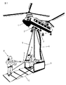
以下、図面を参照して具体的に説明する。図1には、できるだけ多くの消化剤(泡消化剤や水など)を輸送することが可能な巨大なタンクを有する航空機を示す。さらに、これらの航空機は、消防員と救難員とホースとを運搬する最新技術の耐火キャビンを備え、キャビンは消防員と救難員を火災場所へ近づける付属の階段を有し、消火を行うとともに火災にあっている人々を救難し、その人々を外部に連れ出して治療する。これらの装置は、地上の助けなしに、ほとんど全ての高さで、航空機が各種の消火、救難および応急処置の任務を行うことを助ける。これらの航空機は、例えば40階のような相当の高層階で消火を行うことができ、消防車のための空間がない二棟の同一建物の間を飛ぶことができる。そのような航空機は、交通渋滞を克服して目的地に迅速に到達することができ、できる限り多くの生命や財産を救うことができる。 Hereinafter, specific description will be given with reference to the drawings. FIG. 1 shows an aircraft having a huge tank capable of transporting as much digestive agent as possible (foam digester, water, etc.). In addition, these aircraft have state-of-the-art fireproof cabins that carry firefighters, rescuers, and hoses, and the cabins have attached staircases that bring firefighters and rescuers closer to the fire site to extinguish and fire. Rescue people who are in contact with them and take them out to treat them. These devices help aircraft perform various fire fighting, rescue and first aid missions at almost all heights without ground assistance. These aircraft can be extinguished on a fairly high floor, such as the 40th floor, and can fly between two identical buildings that do not have space for fire engines. Such aircraft can overcome traffic jams and quickly reach their destination, saving as much life and property as possible.
図1において、1は、主たる水や泡消火剤のタンク、2は、航空機の下側の消火用キャビンの出口、3は、航空機の下側の泡消化剤のホースの出口、4は、泡消化剤のホース、5は、消火用キャビンを保持するケーブル、6は、泡消化剤のホースを保持する消防員、7は、泡消化剤の噴出部、8は、キャビンの階段上に立っている消防員、9は、主たる消火用キャビン、10は、救難任務を補助するキャビンの階段である。 In FIG. 1, 1 is the main water and foam extinguishant tank, 2 is the exit of the fire extinguishing cabin on the lower side of the aircraft, 3 is the exit of the hose of the lower foam digester on the aircraft, 4 is the foam Digestant hose, 5 is a cable for holding a fire extinguishing cabin, 6 is a firefighter holding a foam digester hose, 7 is a foam extinguishing part, 8 is standing on the cabin stairs Firefighters 9 are main fire-fighting cabins, 10 are cabin stairs to assist in rescue missions.
本発明による航空消火救難ユニットは、図1〜11に示される。図2は、移動式チャンバ11を示し、各チャンバ11は、航空機100の外側の片側に設けられ、2つのチャンバ11は、床面のベース部12に連結されている。それらは、航空機の内部で金属製のレール13に取り付けられている電気リフト14に連結された相互接続延長体16(ケーブル)に連結されている。電気リフト14は、消火救難ユニットを支持して鉛直方向に移動させ、事故現場の壁に安全に接近させる。さらに2つのチャンバ11は、航空機100の外側の屋根に取り付けられた滑車15を経由して航空機100の屋根に連結され、要求された仕事を実行する間、両チャンバ間の平衡が保たれる。航空機100の前後には固定ユニットが設けられるであろう。それらは飛行時に航空機100の両側の空気の流れを許可するように機能し、同時にそれらは、救助すべき追加の負傷者を収容するための固定チャンバとして用いられる。その固定チャンバは、新規の航空機を製造する間に取り付けられ、それらは既存の航空機に取り付けることもできる。
An aircraft fire-fighting rescue unit according to the present invention is shown in FIGS. FIG. 2 shows
消火救難ユニットは、一方の本発明に係るユニットと、航空機の内部に取り付けられた他方の電気リフト14との間で、別の側から延びる弾性支持体17(ケーブル)を介して昇降される。さらに本発明のユニットを構成する2つのチャンバ11の外側の屋根は、この目的のために設計され、航空機の屋根の両側に取り付けられた固有の滑車15を経由して弾性支持延長体17に連結され、消火救難ユニットを降下する間の両チャンバ11の平衡を保つ。
The fire-rescue / rescue unit is raised and lowered between one unit according to the present invention and the other
本発明に係る消火救難ユニットには、火災の消火時に本発明に係るユニットを使用するために、両チャンバ11を接続する消火設備が設けられる。
The fire fighting / rescue unit according to the present invention is provided with a fire extinguishing facility for connecting both
消火救難ユニットは、本発明の各設計に従い、本発明に係るユニットの特定場所に取り付けられた赤外線によって操作される昼夜フォトユニット20に連結され、本発明に係るユニットを取り付ける場所を、異なる航空機の各型式のモードに適合させる。フォトユニット20は、航空機の内部のスクリーンに加えて、本発明に係るユニットのチャンバ11の内部の固有のスクリーンに連結され、航空機のリーダーまたはアシスタントに対して消火救難ユニットの場所を明確に示し、必要ならば救助者が何ら事故なく容易かつ簡単に消火救難ユニットを目的地に降下させることができるように支援する。この場所をさらに明確に示すため、ビジュアルセンサ(可視光線や赤外線を使用)や熱的なフォトセンサ装置、レーダーセンサ装置/オーディオフォトセンサ装置などのあらゆる適宜なフォトセンサ装置を使用することができ、消火救難ユニットのオペレータ(救難員、パイロット、アシスタント)は、制御ユニットに設けられた表示ユニット上でセンサ装置を介して形成された画像を観察する。目的地の場所は、適宜な影響を与える手段を用いて画像に現れる。制御ユニットは、他のオプションとしてプログラムされた情報に従い、目的地を自動的に捉えることができる。レーザー手段、例えば選択または追加の他のマーカーを用いることにより、陸上の人間が着陸場所を定めてもよい。センサ装置は、範囲の対象物または消火救難ユニットに関して分離された範囲の対象物を備え、目的地の距離を定める。とはいえ、目的地に接近するきっかけとして制御ユニットは、目的地を発見して場所を探索する分野において既知のフォト信号を処理する技術的方法を用いて、その目的地を記録し、それに応じて方向を与える。制御ユニットは消火救難ユニットを目的地に向け、コントローラの役割はほとんど影響なく簡単になるであろう。
The fire-rescue rescue unit is connected to the day /
消火救難ユニットは、消火救難ユニットの到達すべき目的地からの距離を割り出すためにセンサシステムを備えるが、これらのセンサを、各チャンバの重量とユニットの全負荷の重量を割り出すために用いてもよい。 The fire-rescue rescue unit is equipped with a sensor system to determine the distance from the destination to which the fire-rescue rescue unit should reach, but these sensors can also be used to determine the weight of each chamber and the total load weight of the unit. Good.
上述の説明によると、この発明が目的としたものを達成することは明らかである。 From the above description, it is apparent that the present invention achieves its intended purpose.
あらゆる種類の異なる航空機に合致して、本発明の主題である航空機消火救難ユニットを既存の航空機に設けられることは、明らかとなろう。 It will be apparent that existing aircraft can be equipped with the aircraft fire-fighting rescue unit, which is the subject of the present invention, to match any kind of different aircraft.
本発明は、発明の概念に含まれる多数の実施形態を有し、これは他の類似の技術的要素に置換可能な全ての特別な要素に加えられるものである。 The present invention has numerous embodiments that fall within the inventive concept, which is in addition to all the special elements that can be replaced by other similar technical elements.
本発明を実施するとき、目的の使用に合致するように設けられた各種の航空機の要求を満たす適宜な材料と大きさを選択することが可能である。 When practicing the present invention, it is possible to select appropriate materials and sizes that meet the demands of various aircraft provided to meet the intended use.
上述の説明を通じて本発明の枠組みの範囲内で、消火救難ユニットを他の形状、大きさ、構成にして用いることができ、それ故、例えば、前述の特徴に言及することが好ましい。さらに、本発明は、上記文脈に限定されず、従って、この代わりに、本発明は、上記文脈に記載の異なる特徴の主および分岐したイメージを全て備え、これは、上記説明を読んだ後に設計と実施の分野に属する人々によって行われる変更や修正に加えられるものである。 Through the above description, the fire-rescue unit can be used in other shapes, sizes and configurations within the framework of the present invention, and therefore, for example, it is preferable to refer to the above-mentioned features. Further, the present invention is not limited to the above context, therefore instead the present invention comprises all the main and branched images of the different features described in the above context, which are designed after reading the above description. In addition to changes and modifications made by people in the field of implementation.
消火救難ユニットの好ましい実施形態の構成を以下に列記する。
(1),ベースに一体に連結された1つのユニットを構成する、航空機の両側の互いに反対側のチャンバからなる固定または移動式の救急要素を備える航空機消火救難ユニット。
(2),あらゆる種類の既存のまたは新規のヘリコプターに取り付けられる(1)の航空機消火救難ユニット。
(3),消火と救難業務を同時に行うことが可能な(1)の航空機消火救難ユニット。
(4),海上の消火と救難業務を行うことが可能な(1)の航空機消火救難ユニット。
(5),平面形状をなし消火救難業務を行うことが可能な(1)の航空機消火救難ユニット。
(6),航空機の屋根の内側に設けられた長手方向の金属製レール上に取り付けられ、消火救難ユニットを昇降する電気リフトを備える消火救難ユニット。
(7),独立した救難員の存在する設計に役立ち、消火救難活動を速める(1)の消火救難ユニット。
(8),航空機の内側および外側に、消火救難ユニットに連結される弾性支持延長体を有する(1)の消火救難ユニット。
(9),2つのチャンバの両側に取り付けられた2本の消火用噴出部と、床の内側の航空機の範囲内におけるタンクからの消化剤とを有する(2)の消火救難ユニット。
(10), 航空機の前後の2本の消火用砲射部を有し、それらが事故現場の消火と冷却を助けるため鉛直方向および水平方向に180°以内で移動可能である(1)の消火救難ユニットを備える航空機。
(11), 目的地を正確に割り出すとともに、将来における評価と研究のために消火救難操作を完全に記録するようなフォトユニットを有する(1)の消火救難ユニット。
(12),形成されたユニットのベースとボディ、部品の内部、および航空機の内部にそれぞれ取り付けられたセンサを有する(1)の消火救難ユニット。
(13),支持延長体に、全ての支持延長体の伸張レベルを測定するセンサが連結される(9)の消火救難ユニット。
(14),形成されたユニットの平均の昇降速度を測定するための速度測定器具を備える(9)の消火救難ユニット。
(15),消火救難ユニットの平均の昇降速度を測定するための速度測定器具を備える(9)の消火救難ユニット。
(16),フォトユニットが下方から航空機のボディに取り付けられる(8)の消火救難ユニット。
(17),フォトユニットがレーダーセンサ装置を備える(8)の消火救難ユニット。
(18),フォトユニットがビジュアルセンサ装置を備える(8)の消火救難ユニット。
(19),形成されたユニットが、形成されたユニットと火災中の建物の壁面との間または事故現場の床面との間の距離を読み取るのを助ける自動センサ装置を備える(9)の消火救難ユニット。
(20),航空機に取り付けられた自動センサを備え、制御ユニットが、消火救難ユニットに取り付けられた第2の自動センサにより与えられた第2の読み込み値と比べた、第1の自動センサに与えられた第1の読み込み値の変化を発見するために機能し、発見された変化を処理し、航空機に対する消火救難ユニットの移動を測定する(9)の消火救難ユニット。
(21),消火救難ユニットとそのユニットの近傍の対象物との間の距離を検出する(9)の消火救難ユニット。
(22),形成されたユニットが、航空機の乗務員が陸上の医療手術室に連絡をつけることを可能にする(19)の消火救難ユニット。
The configuration of the preferred embodiment of the fire-rescue rescue unit is listed below.
(1) An aircraft fire-rescue rescue unit comprising a fixed or mobile emergency element composed of chambers opposite to each other on both sides of an aircraft, constituting one unit integrally connected to the base.
(2) The aircraft fire-fighting rescue unit of (1), which can be attached to any kind of existing or new helicopter.
(3) The aircraft fire-fighting and rescue unit according to (1), which can perform fire-fighting and rescue work at the same time.
(4) The aircraft fire-fighting / rescue unit of (1) capable of performing marine fire-fighting and rescue operations.
(5) The aircraft fire-rescue / rescue unit according to (1), which has a planar shape and can perform fire-fighting rescue operations.
(6) A fire-rescue rescue unit comprising an electric lift that is mounted on a longitudinal metal rail provided on the inside of an aircraft roof and lifts the fire-rescue rescue unit.
(7) The fire-rescue unit of (1), which is useful for designing an independent rescuer and speeds up fire-rescue activities.
(8) The fire-rescue / rescue unit according to (1) having elastic support extensions connected to the fire-rescue / rescue unit on the inside and outside of the aircraft.
(9) The fire-rescue and rescue unit according to (2), comprising two fire-extinguishing jets attached to both sides of the two chambers, and a digestive agent from a tank in the range of the aircraft inside the floor.
(10), Fire extinguishing unit with two fire extinguishing parts before and after the aircraft, which can move within 180 ° vertically and horizontally to help extinguish and cool the accident site An aircraft with a rescue unit.
(11) The fire-rescue unit of (1) having a photo unit that accurately determines the destination and records the fire-rescue operation completely for future evaluation and research.
(12) The fire-rescue / rescue unit according to (1) having sensors attached to the base and body of the formed unit, the interior of the component, and the interior of the aircraft.
(13) The fire-rescue / rescue unit according to (9), wherein a sensor for measuring an extension level of all the support extensions is connected to the support extension.
(14) The fire-rescue / rescue unit according to (9), comprising a speed measuring instrument for measuring an average lifting speed of the formed unit.
(15) The fire-rescue / rescue unit according to (9), comprising a speed measuring instrument for measuring an average lifting speed of the fire-rescue / rescue unit.
(16) The fire-rescue rescue unit according to (8), wherein the photo unit is attached to the aircraft body from below.
(17) The fire-rescue / rescue unit according to (8), wherein the photo unit includes a radar sensor device.
(18) The fire-rescue rescue unit according to (8), wherein the photo unit includes a visual sensor device.
(19) Fire extinguishing according to (9), wherein the formed unit comprises an automatic sensor device which helps to read the distance between the formed unit and the wall of the building under fire or the floor of the accident site Rescue unit.
(20) provided with an automatic sensor attached to the aircraft, the control unit being fed to the first automatic sensor compared to a second reading given by the second automatic sensor attached to the fire-fighting rescue unit The fire-rescue rescue unit of (9), which functions to find a change in the first read value processed, processes the found change, and measures the movement of the fire-rescue rescue unit relative to the aircraft.
(21) The fire-rescue / rescue unit according to (9), wherein a distance between the fire-rescue and rescue unit and an object in the vicinity of the unit is detected.
(22) The fire-rescue rescue unit of (19), wherein the formed unit allows an aircraft crew to contact a medical operating room on land.
本発明は、幾つかの実施形態と合わせて記載されたが、上述の説明に照らして多くの代替、修正および変更が当該技術分野に精通した人々にとって明白であることは、理解されるべきである。したがって、本発明は、付加された請求の範囲と精神の範囲内に含まれる全てのそのような代替、修正および変更を採用する。 Although the present invention has been described in conjunction with some embodiments, it should be understood that many alternatives, modifications and variations will be apparent to those skilled in the art in light of the above description. is there. Accordingly, the present invention employs all such alternatives, modifications and variations that fall within the scope and spirit of the appended claims.
以上の説明より明らかなように、本発明の好ましい形態は、ヘリコプターを航空機として用いて動作可能な改良された消火用装置において、航空機に取り付けられ、水または難燃性の泡消火剤を輸送する貯蔵タンク1と、支持ケーブル5(弾性支持体16,17)とモータ手段(電気リフト14)とを有するキャビン9,11であって、モータ手段14により支持ケーブル5,16,17を介して航空機から降下するキャビン9,11と、貯蔵タンク1からキャビン9,11へ下方に伸延可能であり、消防員により水または泡消火剤が方向付けられるホース4とを備え、キャビン4は、キャビン内からまたはキャビン内へ消防員と負傷者が移動するための少なくとも1つの側方に延びる出入口部18を有する。
さらに好ましくはキャビンが、ヘリコプターの両側に配置された一対の相隔たるキャビンユニット11を備え、キャビンユニット11に取り付けられ、これらキャビンユニット11の間に、かつ、航空機の下方に延在するベース要素12を有する。
さらに好ましくは支持ケーブル17が、航空機の頂部近傍に配置されたプーリー15から伸延し、一対のキャビンユニット11にそれぞれ取り付けられる。
さらに好ましくはホース4が、キャビン11に配置された末端部と、この末端部に設けられ、消防員により向きを変更可能な噴き出し部7とを有する。
さらに好ましくはキャビン9,11が、キャビン9,11からほぼ水平方向に伸延可能な階段10をさらに備える。
さらに好ましくはキャビン11に設けられるセンサ20であって、キャビン11の建物19および火災場所への近接状態と熱を検出するセンサ20をさらに備える。
As is apparent from the above description, the preferred form of the present invention is an improved fire extinguishing device operable with a helicopter as an aircraft, attached to the aircraft and transporting water or a flame retardant foam. A
More preferably, the cabin comprises a pair of spaced
More preferably, a
More preferably, the
More preferably, the
More preferably, the
1 タンク
4 ホース
5 ケーブル
7 噴出部
9,11 キャビン
10 階段
12 ベース部
14 電気リフト
16 相互接続延長体
17 弾性支持延長体
18 出入口部
20 フォトユニット
DESCRIPTION OF SYMBOLS 1
Claims (6)
前記航空機に取り付けられ、水または難燃性の泡消火剤を輸送する貯蔵タンクと、
支持ケーブルとモータ手段とを有するキャビンであって、前記モータ手段により前記支持ケーブルを介して前記航空機から降下するキャビンと、
前記貯蔵タンクから前記キャビンへ下方に伸延可能であり、消防員により前記水または泡消火剤が方向付けられるホースとを備え、
前記キャビンは、前記キャビン内からまたは前記キャビン内へ消防員と負傷者が移動するための少なくとも1つの側方に延びる出入口部を有する装置。 In an improved fire extinguishing device that can operate using a helicopter as an aircraft,
A storage tank attached to the aircraft for transporting water or flame retardant foam,
A cabin having a support cable and motor means, the cabin descending from the aircraft via the support cable by the motor means;
A hose that can be extended downward from the storage tank to the cabin and to which the water or foam is directed by a firefighter,
The cabin has an at least one laterally extending doorway for a firefighter and an injured person to move from within or into the cabin.
前記キャビンは、前記ヘリコプターの両側に配置された一対の相隔たるキャビンユニットを備え、前記キャビンユニットに取り付けられ、これらキャビンユニットの間に、かつ、前記航空機の下方に延在するベース要素を有する装置。 The apparatus of claim 1.
The cabin includes a pair of spaced cabin units disposed on opposite sides of the helicopter, and has a base element attached to the cabin unit and extending between the cabin units and below the aircraft. .
前記支持ケーブルは、前記航空機の頂部近傍に配置されたプーリーから伸延し、前記一対のキャビンユニットにそれぞれ取り付けられる装置。 The apparatus of claim 2.
The support cable extends from a pulley disposed near the top of the aircraft and is attached to the pair of cabin units.
前記ホースは、前記キャビンに配置された末端部と、この末端部に設けられ、消防員により向きを変更可能な噴き出し部とを有する装置。 The apparatus of claim 1.
The said hose is an apparatus which has the terminal part arrange | positioned at the said cabin, and the ejection part which is provided in this terminal part and can change direction by a fireman.
前記キャビンは、前記キャビンからほぼ水平方向に伸延可能な階段をさらに備える装置。 The apparatus of claim 1.
The cabin further comprises a staircase that can extend from the cabin in a substantially horizontal direction.
前記キャビンに設けられるセンサであって、前記キャビンの建物および火災場所への近接状態と熱を検出するセンサをさらに備える装置。 The apparatus of claim 1.
The apparatus further provided with the sensor which is provided in the said cabin, Comprising: The proximity | contact state and heat of the said building to the building and the fire place are detected.
Priority Applications (1)
| Application Number | Priority Date | Filing Date | Title |
|---|---|---|---|
| JP2009133466A JP2010280251A (en) | 2009-06-02 | 2009-06-02 | Fire extinguishing rescue unit attached to helicopter |
Applications Claiming Priority (1)
| Application Number | Priority Date | Filing Date | Title |
|---|---|---|---|
| JP2009133466A JP2010280251A (en) | 2009-06-02 | 2009-06-02 | Fire extinguishing rescue unit attached to helicopter |
Publications (1)
| Publication Number | Publication Date |
|---|---|
| JP2010280251A true JP2010280251A (en) | 2010-12-16 |
Family
ID=43537430
Family Applications (1)
| Application Number | Title | Priority Date | Filing Date |
|---|---|---|---|
| JP2009133466A Pending JP2010280251A (en) | 2009-06-02 | 2009-06-02 | Fire extinguishing rescue unit attached to helicopter |
Country Status (1)
| Country | Link |
|---|---|
| JP (1) | JP2010280251A (en) |
Cited By (8)
| Publication number | Priority date | Publication date | Assignee | Title |
|---|---|---|---|---|
| CN102058943A (en) * | 2011-01-06 | 2011-05-18 | 刘佳 | Design scheme for lifting high-rise fire rescue capsule and fire-fighting squirt gun by helicopter or airship |
| CN102914217A (en) * | 2012-10-17 | 2013-02-06 | 北京机械设备研究所 | Method for shooting fire-extinguishing bullet for high-rise building fire-extinguishing system |
| JP2017104365A (en) * | 2015-12-11 | 2017-06-15 | 株式会社ディスコ | Manned drone |
| CN110507923A (en) * | 2019-07-02 | 2019-11-29 | 上海鲲哥无人机科技有限公司 | The control method of fire-fighting and rescue platform based on aircraft |
| DE102019202976A1 (en) * | 2019-03-05 | 2020-09-10 | Volkswagen Aktiengesellschaft | Evacuation drone |
| CN114344763A (en) * | 2022-01-11 | 2022-04-15 | 北京机械设备研究所 | Device for quickly replacing fire extinguishing tank and method for replacing fire extinguishing tank |
| CN114470557A (en) * | 2022-01-26 | 2022-05-13 | 武汉建工集团股份有限公司 | High-rise building fire safety robot |
| CN115430084A (en) * | 2022-09-13 | 2022-12-06 | 邓秋波 | High-rise building indoor rescue system and use method thereof |
Citations (14)
| Publication number | Priority date | Publication date | Assignee | Title |
|---|---|---|---|---|
| US3273651A (en) * | 1966-09-20 | Andrews fire fighting equipment | ||
| US3934847A (en) * | 1974-10-04 | 1976-01-27 | Bentivegna Pasquale P | Rescue capsule for use with a helicopter |
| US4195694A (en) * | 1978-08-14 | 1980-04-01 | Gizzarelli Nicholas Sr | Rescue vehicle |
| JPH03157298A (en) * | 1989-11-13 | 1991-07-05 | Mitsubishi Heavy Ind Ltd | Fire fighting helicopter |
| JPH07277287A (en) * | 1994-04-11 | 1995-10-24 | Mitsubishi Heavy Ind Ltd | Helicopter with low center of gravity |
| JPH07277289A (en) * | 1994-04-05 | 1995-10-24 | Mitsubishi Heavy Ind Ltd | Rescue helicopter |
| JPH08150225A (en) * | 1994-11-28 | 1996-06-11 | Masaru Asahara | Automatic fire extinguisher for aircraft |
| JPH09286397A (en) * | 1996-04-23 | 1997-11-04 | Mitsubishi Heavy Ind Ltd | Automatic hoisting device for hoist cable |
| JPH10273097A (en) * | 1997-03-28 | 1998-10-13 | Shin Meiwa Ind Co Ltd | Liquid discharge device of helicopter for fire fighting |
| JP2003026097A (en) * | 2001-07-17 | 2003-01-29 | Yoshikazu Kikuoka | Helicopter |
| US20060175429A1 (en) * | 2005-02-04 | 2006-08-10 | Lanigan John J Jr | Fire fighting system |
| JP2007505799A (en) * | 2003-09-16 | 2007-03-15 | コーチャギン・パヴェル・ヴラディミロヴィッチ | Equipment for fire fighting, rescue and construction in high-rise buildings |
| JP2007091012A (en) * | 2005-09-28 | 2007-04-12 | Shin Meiwa Ind Co Ltd | Helicopter-mounted fluid discharge system and helicopter equipped therewith |
| WO2007132454A2 (en) * | 2006-05-11 | 2007-11-22 | Olive Engineering Ltd. | Aircraft with cables to deploy hanging cabin |
-
2009
- 2009-06-02 JP JP2009133466A patent/JP2010280251A/en active Pending
Patent Citations (14)
| Publication number | Priority date | Publication date | Assignee | Title |
|---|---|---|---|---|
| US3273651A (en) * | 1966-09-20 | Andrews fire fighting equipment | ||
| US3934847A (en) * | 1974-10-04 | 1976-01-27 | Bentivegna Pasquale P | Rescue capsule for use with a helicopter |
| US4195694A (en) * | 1978-08-14 | 1980-04-01 | Gizzarelli Nicholas Sr | Rescue vehicle |
| JPH03157298A (en) * | 1989-11-13 | 1991-07-05 | Mitsubishi Heavy Ind Ltd | Fire fighting helicopter |
| JPH07277289A (en) * | 1994-04-05 | 1995-10-24 | Mitsubishi Heavy Ind Ltd | Rescue helicopter |
| JPH07277287A (en) * | 1994-04-11 | 1995-10-24 | Mitsubishi Heavy Ind Ltd | Helicopter with low center of gravity |
| JPH08150225A (en) * | 1994-11-28 | 1996-06-11 | Masaru Asahara | Automatic fire extinguisher for aircraft |
| JPH09286397A (en) * | 1996-04-23 | 1997-11-04 | Mitsubishi Heavy Ind Ltd | Automatic hoisting device for hoist cable |
| JPH10273097A (en) * | 1997-03-28 | 1998-10-13 | Shin Meiwa Ind Co Ltd | Liquid discharge device of helicopter for fire fighting |
| JP2003026097A (en) * | 2001-07-17 | 2003-01-29 | Yoshikazu Kikuoka | Helicopter |
| JP2007505799A (en) * | 2003-09-16 | 2007-03-15 | コーチャギン・パヴェル・ヴラディミロヴィッチ | Equipment for fire fighting, rescue and construction in high-rise buildings |
| US20060175429A1 (en) * | 2005-02-04 | 2006-08-10 | Lanigan John J Jr | Fire fighting system |
| JP2007091012A (en) * | 2005-09-28 | 2007-04-12 | Shin Meiwa Ind Co Ltd | Helicopter-mounted fluid discharge system and helicopter equipped therewith |
| WO2007132454A2 (en) * | 2006-05-11 | 2007-11-22 | Olive Engineering Ltd. | Aircraft with cables to deploy hanging cabin |
Cited By (11)
| Publication number | Priority date | Publication date | Assignee | Title |
|---|---|---|---|---|
| CN102058943A (en) * | 2011-01-06 | 2011-05-18 | 刘佳 | Design scheme for lifting high-rise fire rescue capsule and fire-fighting squirt gun by helicopter or airship |
| CN102914217A (en) * | 2012-10-17 | 2013-02-06 | 北京机械设备研究所 | Method for shooting fire-extinguishing bullet for high-rise building fire-extinguishing system |
| CN102914217B (en) * | 2012-10-17 | 2014-06-18 | 北京机械设备研究所 | Method for shooting fire-extinguishing bullet for high-rise building fire-extinguishing system |
| JP2017104365A (en) * | 2015-12-11 | 2017-06-15 | 株式会社ディスコ | Manned drone |
| DE102019202976A1 (en) * | 2019-03-05 | 2020-09-10 | Volkswagen Aktiengesellschaft | Evacuation drone |
| CN110507923A (en) * | 2019-07-02 | 2019-11-29 | 上海鲲哥无人机科技有限公司 | The control method of fire-fighting and rescue platform based on aircraft |
| CN114344763A (en) * | 2022-01-11 | 2022-04-15 | 北京机械设备研究所 | Device for quickly replacing fire extinguishing tank and method for replacing fire extinguishing tank |
| CN114344763B (en) * | 2022-01-11 | 2023-09-08 | 北京机械设备研究所 | Device for quickly replacing fire extinguishing tank and method for replacing fire extinguishing tank |
| CN114470557A (en) * | 2022-01-26 | 2022-05-13 | 武汉建工集团股份有限公司 | High-rise building fire safety robot |
| CN115430084A (en) * | 2022-09-13 | 2022-12-06 | 邓秋波 | High-rise building indoor rescue system and use method thereof |
| CN115430084B (en) * | 2022-09-13 | 2023-04-14 | 邓秋波 | High-rise building indoor rescue system and use method thereof |
Similar Documents
| Publication | Publication Date | Title |
|---|---|---|
| JP2010280251A (en) | Fire extinguishing rescue unit attached to helicopter | |
| US4406351A (en) | Emergency escape system for use in multistoried buildings | |
| US7597175B2 (en) | Reed's high-rise emergency rescue egress system | |
| CN108434628B (en) | Mobile fire-fighting system and method for unmanned mechanical garage | |
| KR20190023580A (en) | Tunnel integrated disaster prevention system capable of accident monitoring, fire disaster prevention, and refugee relief into a tunnel | |
| CN102107734A (en) | Helicopter to which fire-fighting and rescue facility can be attached and connected | |
| US20060175429A1 (en) | Fire fighting system | |
| KR20190024856A (en) | Tunnel integrated disaster prevention system capable of accident monitoring, fire disaster prevention, and refugee relief into a tunnel | |
| KR101933376B1 (en) | Life-saving ladder using boarding chute and chute | |
| KR20130123224A (en) | Rescue and extinguishing apparatus for fire | |
| CN103691072B (en) | rescue system for high-rise building | |
| US20090266566A1 (en) | Fire fighting and rescue unit attachable helicopter | |
| CN103007453A (en) | Firefighting rescue system for high-rise building | |
| US5497855A (en) | Exterior fire fighting and evacuation system for high rise buildings | |
| KR20100135582A (en) | Firefighting and rescue unit attachable helicopter | |
| EP2256037A1 (en) | Fire fighting and rescue unit attachable to a helicopter | |
| KR20070024457A (en) | High-rise fire fighting, rescue and construction equipement | |
| CN105983189A (en) | Movable fire emergency refuge cabin and work method thereof | |
| KR102095630B1 (en) | Guidance rovot for disaster relief | |
| CN111731969A (en) | Escape platform and escape platform system | |
| RU2694850C1 (en) | Method and system of means of evacuating people from a building during abnormal development of fire | |
| EP2858724B1 (en) | Inflatable system for emergency evacuation from structures | |
| CN203075490U (en) | High-rise building fire rescue system | |
| CN212374657U (en) | Escape platform and escape platform system | |
| RU2651656C1 (en) | Device for people emergency evacuation from the high-rise buildings |
Legal Events
| Date | Code | Title | Description |
|---|---|---|---|
| A621 | Written request for application examination |
Free format text: JAPANESE INTERMEDIATE CODE: A621 Effective date: 20120525 |
|
| A977 | Report on retrieval |
Free format text: JAPANESE INTERMEDIATE CODE: A971007 Effective date: 20130830 |
|
| A131 | Notification of reasons for refusal |
Free format text: JAPANESE INTERMEDIATE CODE: A131 Effective date: 20130903 |
|
| A02 | Decision of refusal |
Free format text: JAPANESE INTERMEDIATE CODE: A02 Effective date: 20140218 |