JP2010230802A - Projector - Google Patents
Projector Download PDFInfo
- Publication number
- JP2010230802A JP2010230802A JP2009075939A JP2009075939A JP2010230802A JP 2010230802 A JP2010230802 A JP 2010230802A JP 2009075939 A JP2009075939 A JP 2009075939A JP 2009075939 A JP2009075939 A JP 2009075939A JP 2010230802 A JP2010230802 A JP 2010230802A
- Authority
- JP
- Japan
- Prior art keywords
- light
- polarization
- projector
- compensation plate
- liquid crystal
- Prior art date
- Legal status (The legal status is an assumption and is not a legal conclusion. Google has not performed a legal analysis and makes no representation as to the accuracy of the status listed.)
- Withdrawn
Links
Images


Classifications
-
- G—PHYSICS
- G03—PHOTOGRAPHY; CINEMATOGRAPHY; ANALOGOUS TECHNIQUES USING WAVES OTHER THAN OPTICAL WAVES; ELECTROGRAPHY; HOLOGRAPHY
- G03B—APPARATUS OR ARRANGEMENTS FOR TAKING PHOTOGRAPHS OR FOR PROJECTING OR VIEWING THEM; APPARATUS OR ARRANGEMENTS EMPLOYING ANALOGOUS TECHNIQUES USING WAVES OTHER THAN OPTICAL WAVES; ACCESSORIES THEREFOR
- G03B21/00—Projectors or projection-type viewers; Accessories therefor
- G03B21/14—Details
- G03B21/20—Lamp housings
- G03B21/208—Homogenising, shaping of the illumination light
-
- G—PHYSICS
- G02—OPTICS
- G02B—OPTICAL ELEMENTS, SYSTEMS OR APPARATUS
- G02B5/00—Optical elements other than lenses
- G02B5/30—Polarising elements
- G02B5/3025—Polarisers, i.e. arrangements capable of producing a definite output polarisation state from an unpolarised input state
-
- G—PHYSICS
- G03—PHOTOGRAPHY; CINEMATOGRAPHY; ANALOGOUS TECHNIQUES USING WAVES OTHER THAN OPTICAL WAVES; ELECTROGRAPHY; HOLOGRAPHY
- G03B—APPARATUS OR ARRANGEMENTS FOR TAKING PHOTOGRAPHS OR FOR PROJECTING OR VIEWING THEM; APPARATUS OR ARRANGEMENTS EMPLOYING ANALOGOUS TECHNIQUES USING WAVES OTHER THAN OPTICAL WAVES; ACCESSORIES THEREFOR
- G03B21/00—Projectors or projection-type viewers; Accessories therefor
- G03B21/14—Details
- G03B21/20—Lamp housings
- G03B21/2073—Polarisers in the lamp house
-
- H—ELECTRICITY
- H04—ELECTRIC COMMUNICATION TECHNIQUE
- H04N—PICTORIAL COMMUNICATION, e.g. TELEVISION
- H04N9/00—Details of colour television systems
- H04N9/12—Picture reproducers
- H04N9/31—Projection devices for colour picture display, e.g. using electronic spatial light modulators [ESLM]
- H04N9/3102—Projection devices for colour picture display, e.g. using electronic spatial light modulators [ESLM] using two-dimensional electronic spatial light modulators
- H04N9/3105—Projection devices for colour picture display, e.g. using electronic spatial light modulators [ESLM] using two-dimensional electronic spatial light modulators for displaying all colours simultaneously, e.g. by using two or more electronic spatial light modulators
-
- H—ELECTRICITY
- H04—ELECTRIC COMMUNICATION TECHNIQUE
- H04N—PICTORIAL COMMUNICATION, e.g. TELEVISION
- H04N9/00—Details of colour television systems
- H04N9/12—Picture reproducers
- H04N9/31—Projection devices for colour picture display, e.g. using electronic spatial light modulators [ESLM]
- H04N9/3141—Constructional details thereof
- H04N9/315—Modulator illumination systems
- H04N9/3167—Modulator illumination systems for polarizing the light beam
Abstract
Description
本発明は、照明光を光変調装置によって変調し、変調された像光を投射するプロジェクターに関する。 The present invention relates to a projector that modulates illumination light by a light modulation device and projects modulated image light.
従来のプロジェクターとして、光変調において光を反射する所謂反射型の液晶パネルを用いたプロジェクターが知られており、特に、液晶パネルと偏光ビームスプリッタとの間に配置される1/4位相差板や位相差補償素子の保持枠を黒色に塗装するものが知られている(特許文献1参照)。なお、液晶パネル周辺の部材に遮光用の黒色塗料や黒色テープを施すことは、光変調において光を透過する所謂透過型の液晶パネルを用いたプロジェクターにおいても行われている(特許文献2参照)。 As a conventional projector, a projector using a so-called reflective liquid crystal panel that reflects light in light modulation is known, and in particular, a quarter phase plate disposed between a liquid crystal panel and a polarizing beam splitter, One in which the holding frame of the phase difference compensation element is painted black (see Patent Document 1) is known. It should be noted that applying a black paint or black tape for shielding light to members around the liquid crystal panel is also performed in a projector using a so-called transmissive liquid crystal panel that transmits light in light modulation (see Patent Document 2). .
しかしながら、黒色塗料等により不要光の遮光処理を行っても、不要光が完全には吸収されず、成分の一部が散乱し、漏れ光が発生する場合がある。特に、当該黒色塗料等の施された表面に凹凸があることで、吸収されない不要光の偏光状態が乱れて、液晶パネルから出射する変調光の偏光状態と同じ偏光状態の漏れ光成分が発生し得る。この場合、例えば反射型の液晶パネルを用いたプロジェクターにおいて、当該漏れ光成分が変調光とともに投射され、投影画像のコントラスト低下を招く可能性がある。また、吸収されない不要光は、迷光の発生原因ともなる。 However, even if unnecessary light is shielded with black paint or the like, unnecessary light may not be completely absorbed, and some of the components may be scattered and leak light may be generated. In particular, the uneven surface on the surface of the black paint, etc. disturbs the polarization state of unwanted light that is not absorbed, and a leakage light component with the same polarization state as the polarization state of the modulated light emitted from the liquid crystal panel is generated. obtain. In this case, for example, in a projector using a reflective liquid crystal panel, the leakage light component may be projected together with the modulated light, leading to a decrease in contrast of the projected image. Unnecessary light that is not absorbed also causes stray light.
そこで、本発明は、液晶パネル等の光変調素子の周辺で発生する不要光に起因する投影画像のコントラスト低下を抑制することが可能なプロジェクターを提供することを目的とする。 SUMMARY An advantage of some aspects of the invention is that it provides a projector capable of suppressing a reduction in contrast of a projection image caused by unnecessary light generated around a light modulation element such as a liquid crystal panel.
上記課題を解決するため、本発明に係る第1のプロジェクターは、入射した光の偏光状態を変化させる光変調素子と、光変調素子内における有効画素領域の外縁に沿って設けられ、入射する光の偏光状態を維持したまま反射する平坦面を含む偏光維持反射部とを備える。 In order to solve the above problems, a first projector according to the present invention includes a light modulation element that changes a polarization state of incident light, and an incident light provided along an outer edge of an effective pixel region in the light modulation element. And a polarization maintaining / reflecting unit including a flat surface that reflects the light while maintaining the polarization state.
上記プロジェクターでは、有効画素領域の外縁に沿って設けられた偏光維持反射部が、入射する光の偏光状態を維持したまま反射する平坦面を含むため、有効画素領域外に入射した不要光の偏光状態の乱れを抑えることができ、かかる不要光から変調光の偏光状態と一致する成分が発生することを防止できる。従って、上記プロジェクターは、光源から発生させた照明光を光変調素子によって変調し投射光学系によって投射するにあたって、上記のような不要光から漏れ光や迷光が発生することを低減し、延いては投影画像のコントラスト低下を抑制することができる。 In the projector described above, the polarization maintaining / reflecting unit provided along the outer edge of the effective pixel area includes a flat surface that reflects the polarization state of the incident light while maintaining the polarization state of the incident light. The disturbance of the state can be suppressed, and the generation of a component that matches the polarization state of the modulated light from the unnecessary light can be prevented. Therefore, when the projector modulates the illumination light generated from the light source with the light modulation element and projects it with the projection optical system, it reduces the occurrence of leakage light and stray light from the unnecessary light as described above. A decrease in contrast of the projected image can be suppressed.
上記課題を解決するため、本発明に係る第2のプロジェクターは、入射した光の偏光状態を変化させる光変調素子と、光変調素子内における有効画素領域の外縁に沿って設けられ、入射する光の成分のうち特定の偏光状態の成分を吸収する偏光吸収部とを備える。 In order to solve the above-described problem, a second projector according to the present invention includes a light modulation element that changes a polarization state of incident light and an incident light that is provided along an outer edge of an effective pixel region in the light modulation element. And a polarization absorbing part that absorbs a component in a specific polarization state.
上記プロジェクターでは、有効画素領域の外縁に沿って設けられた偏光吸収部が、入射する光の成分のうち特定の偏光状態の成分を吸収するため、有効画素領域外に入射した不要光から変調光の偏光状態と一致する成分が発生することを防止できる。従って、上記プロジェクターは、光源から発生させた照明光を光変調素子によって変調し投射光学系によって投射するにあたって、上記のような不要光から漏れ光や迷光が発生することを低減し、延いては投影画像のコントラスト低下を抑制することが可能となる。 In the projector described above, the polarized light absorber provided along the outer edge of the effective pixel region absorbs a component of a specific polarization state out of the incident light components. Therefore, the modulated light is generated from unnecessary light incident outside the effective pixel region. It is possible to prevent the occurrence of a component that matches the polarization state. Therefore, when the projector modulates the illumination light generated from the light source with the light modulation element and projects it with the projection optical system, it reduces the occurrence of leakage light and stray light from the unnecessary light as described above. It is possible to suppress a decrease in contrast of the projected image.
また、本発明の具体的な態様によれば、光変調素子が、反射型液晶パネルであり、光変調素子に入射した光の第1方向及び第2方向のうちいずれか一方の偏光を透過させ、他方の偏光を反射する偏光分離素子をさらに備える。この場合、偏光分離素子での透過又は反射によって、非変調光や有効画素領域外からの戻り光である不要な光成分と、反射型液晶パネルからの変調光とが分離可能となる。 Further, according to a specific aspect of the present invention, the light modulation element is a reflective liquid crystal panel, and transmits either polarized light in the first direction or the second direction of light incident on the light modulation element. And a polarization separation element that reflects the other polarized light. In this case, unnecessary light components that are non-modulated light or return light from outside the effective pixel region and modulated light from the reflective liquid crystal panel can be separated by transmission or reflection at the polarization separation element.
また、本発明の別の態様では、プロジェクターが、光変調素子に入射する光の偏光状態を補償する光学補償板と、光変調素子の有効画素領域の外縁に沿って光学補償板を周囲から囲んで支持する補償板フレーム部とをさらに有し、偏光維持反射部又は偏光吸収部が、補償板フレーム部に形成されている。この場合、補償板フレーム部において不要光の偏光状態を適切に調整することができる。 In another aspect of the invention, the projector surrounds the optical compensator from the periphery along the optical compensator for compensating the polarization state of the light incident on the light modulator, and the outer edge of the effective pixel region of the light modulator. And a polarization maintaining / reflecting portion or a polarization absorbing portion is formed on the compensation plate frame portion. In this case, the polarization state of the unnecessary light can be appropriately adjusted in the compensation plate frame part.
また、本発明のさらに別の態様では、第1のプロジェクターにおける偏光維持反射部が、補償板フレーム部の表面をミラー加工することにより形成されている。この場合、ミラー加工により形成された補償板フレーム部の表面で、不要光の偏光状態を維持して反射させることができる。 In yet another aspect of the present invention, the polarization maintaining / reflecting portion in the first projector is formed by mirroring the surface of the compensation plate frame portion. In this case, it is possible to reflect the unnecessary light while maintaining the polarization state of the unnecessary light on the surface of the compensation plate frame portion formed by mirror processing.
また、本発明のさらに別の態様では、第1のプロジェクターにおける偏光維持反射部が、補償板フレーム部にミロ材を用いることにより形成されている。この場合、ミロ材により形成された補償板フレーム部の表面で、不要光の偏光状態を維持して反射させることができる。 According to still another aspect of the invention, the polarization maintaining / reflecting portion in the first projector is formed by using a Milo material for the compensation plate frame portion. In this case, it is possible to reflect the unnecessary light while maintaining the polarization state of the unnecessary light on the surface of the compensation plate frame portion formed of the miro material.
また、本発明のさらに別の態様では、第1のプロジェクターにおける偏光維持反射部が、補償板フレーム部の表面を鏡面仕上げすることにより形成されている。この場合、鏡面仕上げにより形成された補償板フレーム部の表面で、不要光の偏光状態を維持して反射させることができる。 According to still another aspect of the invention, the polarization maintaining / reflecting portion in the first projector is formed by mirror-finishing the surface of the compensation plate frame portion. In this case, the surface of the compensation plate frame portion formed by mirror finishing can be reflected while maintaining the polarization state of unnecessary light.
また、本発明のさらに別の態様では、第2のプロジェクターにおける偏光吸収部が、補償板フレーム部の表面に貼付けられたシート状の有機偏光部材により形成されている。この場合、シート状の有機偏光部材によって不要光を吸収して当該不要光に起因する漏れ光や迷光の発生を防止することができる。 In still another aspect of the invention, the polarization absorbing portion in the second projector is formed by a sheet-like organic polarizing member attached to the surface of the compensation plate frame portion. In this case, unnecessary light can be absorbed by the sheet-like organic polarizing member, and leakage light and stray light due to the unnecessary light can be prevented.
また、本発明のさらに別の態様では、光学補償板と補償板フレーム部との接着面に対応して形成される第2偏光維持反射部をさらに有する。この場合、光学補償板と補償板フレーム部との接着面において不要光の偏光状態が乱れて漏れ光や迷光が発生することを抑制できる。 According to still another aspect of the present invention, there is further provided a second polarization maintaining / reflecting part formed corresponding to the adhesive surface between the optical compensator and the compensator frame part. In this case, it is possible to suppress the occurrence of leakage light or stray light due to the polarization state of unnecessary light being disturbed on the adhesive surface between the optical compensation plate and the compensation plate frame.
また、本発明のさらに別の態様では、偏光維持反射部又は偏光吸収部が、光変調素子の表面に形成されている。この場合、光変調素子の表面上において不要光の偏光状態を適切に調整することができる。 In still another aspect of the present invention, the polarization maintaining reflection part or the polarization absorption part is formed on the surface of the light modulation element. In this case, the polarization state of unnecessary light can be appropriately adjusted on the surface of the light modulation element.
〔第1実施形態〕
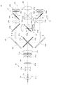
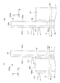
図1は、本発明の第1実施形態に係るプロジェクターの光学系の構成を説明する概念的な平面図である。
[First Embodiment]
FIG. 1 is a conceptual plan view for explaining the configuration of the optical system of the projector according to the first embodiment of the invention.
本プロジェクター10は、光源光を発生する光源装置21と、光源装置21から出射された光源光を赤緑青(RGB)の3色に分離する色分離導光光学系23と、色分離導光光学系23から出射された各色の光源光によって照明される光変調部25と、光変調部25から出射された各色の像光を合成するクロスダイクロイックプリズム27と、クロスダイクロイックプリズム27を経た像光をスクリーン(不図示)に投射するための投射光学系である投射レンズ29とを備える。このうち、光源装置21、色分離導光光学系23、光変調部25、及びクロスダイクロイックプリズム27は、スクリーンに投射すべき像光を形成する画像形成装置となっている。
The
以上のプロジェクター10において、光源装置21は、光源ランプ21aと、凹レンズ21bと、一対のフライアイ光学系21d,21eと、偏光変換部材21gと、重畳レンズ21iとを備える。このうち、光源ランプ21aは、例えば高圧水銀ランプその他の発光管11aと、光源光を回収して前方に出射させる凹面鏡11bとを備える。凹レンズ21bは、光源ランプ21aからの光源光を平行化する役割を有する。光源ランプ21aの凹面鏡11bが、放物面である場合、凹レンズ21bを省略することもできる。一対のフライアイ光学系21d,21eは、システム光軸SAと直交する面内にマトリックス状に配置された複数の要素レンズからなり、これらの要素レンズによって凹レンズ21bを経た光源ランプ21aからの光源光を分割して個別に集光・発散させる。偏光変換部材21gは、フライアイ光学系21eから出射した光源光を例えば図1の紙面に平行なP偏光成分のみに変換して光路下流側光学系に供給する。重畳レンズ21iは、偏光変換部材21gを経た光源光を全体として適宜収束させることにより、光変調部25に設けた各色の光変調装置に対する重畳照明を可能にする。つまり、両フライアイ光学系21d,21eと重畳レンズ21iとを経た光源光は、以下に詳述する色分離導光光学系23を経て、光変調部25に設けられた各色の光変調装置60r,60g,60bを均一に重畳照明する。
In the
色分離導光光学系23は、クロスダイクロイックミラー23aと、ダイクロイックミラー23bと、反射ミラー23j,23kとを備える。この色分離導光光学系23において、光源装置21からの略白色の光源光は、クロスダイクロイックミラー23aに入射する。クロスダイクロイックミラー23aを構成する一方の第1ダイクロイックミラー31aで反射された赤(R)光は、反射ミラー23jで反射されダイクロイックミラー23bを透過して、次段に設けたフィールドレンズ24rを経て光束の状態が調整され、例えばP偏光のまま、反射型偏光板である偏光分離素子32rに入射する。同様に、第2ダイクロイックミラー31aで反射された緑(G)光は、反射ミラー23jで反射されダイクロイックミラー23bでも反射されて、次段に設けたフィールドレンズ24gを経て光束の状態が調整され、例えばP偏光のまま、反射型偏光板である偏光分離素子32gに入射する。一方、クロスダイクロイックミラー23aを構成する他方の第2ダイクロイックミラー31bで反射された青(B)光は、反射ミラー23kで反射されて、次段に設けたフィールドレンズ24bを経て光束の状態が調整され、例えばP偏光のまま、反射型偏光板である偏光分離素子32bに入射する。
The color separation light guide
光変調部25は、3つの偏光分離素子32r,32g,32bと、3つの反射型の光変調装置60r,60g,60bとを備える。3つの偏光分離素子32r,32g,32bは、例えばワイヤーグリッド型の偏光分離素子であり、P偏光を透過させ、S偏光を反射する。3つの反射型の光変調装置60r,60g,60bは、液晶パネル61r,61g,61bと、光学補償板62r,62g,62bとをそれぞれ備える。液晶パネル61r,61g,61bは、入射した光の偏光状態を変化させて反射することによって空間的強度分布を変調し画像光の形成を可能にする非発光反射型の光変調素子である。光学補償板62r,62g,62bは、液晶パネル61r,61g,61bへの入射光及び出射光の偏光状態を調整することで、液晶の特性を光学的に補償している。
The
以上において、R光用の偏光分離素子32r及び光変調装置60rは、R色の光源光を画像情報に基づいて2次元的に輝度変調するためのR光用のライトバルブV1を構成する。同様に、G光用の偏光分離素子32g及び光変調装置60gは、G色の光源光を画像情報に基づいて2次元的に輝度変調するためのG光用のライトバルブV2を構成する。また、B光用の偏光分離素子32b及び光変調装置60bは、B色の光源光を画像情報に基づいて2次元的に輝度変調するためのB光用のライトバルブV3を構成する。
In the above, the
R光用の第1の光変調装置60rには、色分離導光光学系23のダイクロイックミラー23bを透過することによって分岐されたR光が、偏光分離素子32rを介して入射する。G光用の第2の光変調装置60gには、色分離導光光学系23のダイクロイックミラー23bで反射されることによって分岐されたG光が、偏光分離素子32gを介して入射する。B光用の第3の光変調装置60bには、色分離導光光学系23の第2ダイクロイックミラー31bで反射されることによって分岐されたB光が、偏光分離素子32bを介して入射する。
The R light branched by being transmitted through the
各光変調装置60r,60g,60bにおいて、光学補償板62r,62g,62bを経て各液晶パネル61r,61g,61bにそれぞれ入射した3色の光は、各液晶パネル61r,61g,61bに電気的信号として入力された駆動信号或いは画像信号に応じて変調される。その際、偏光分離素子32r,32g,32bによって、各光変調装置60r,60g,60bに入射する光源光の偏光方向が正確にP偏光となるように調整されるとともに、各光変調装置60r,60g,60bから出射される変調光からS偏光の成分光が像光として取り出される。この際、光学補償板62r,62g,62bは、通過する光の偏光状態を調整することで、液晶パネル61r,61g,61bに残存するリタデーションを実効的に相殺する光学的な補償を行っている。光学補償板62r,62g,62bでの補償により、変調光のコントラストを向上させることができる。
In each of the
クロスダイクロイックプリズム27は、光合成部材であり、4つの直角プリズムを貼り合わせた平面視略正方形状をなし、直角プリズム同士を貼り合わせた界面には、X字状に交差する一対の誘電体多層膜27a,27bが形成されている。一方の第1誘電体多層膜27aはR光を反射し、他方の第2誘電体多層膜27bはB光を反射する。このクロスダイクロイックプリズム27は、光変調装置60rからのR光を第1誘電体多層膜27aで反射して進行方向左側に出射させ、光変調装置60gからのG光を第1及び第2誘電体多層膜27a,27bを介して直進・出射させ、光変調装置60bからのB光を第2誘電体多層膜27bで反射して進行方向右側に出射させる。
The cross
投射レンズ29は、クロスダイクロイックプリズム27で合成されたカラーの像光を、所望の倍率でスクリーン(不図示)上に投射する。つまり、各液晶パネル61r,61g,61bに入力された駆動信号或いは画像信号に対応する所望の倍率のカラー動画やカラー静止画がスクリーン上に投射される。
The
本実施形態では、以上のような反射型の液晶パネル61r,61g,61bを用いたプロジェクター10において、照明光の成分のうち、各光変調装置60r,60g,60bで有効利用されることのない不要光の処理を行い、不要光から漏れ光や迷光が発生することを低減し、延いては投影画像のコントラスト低下を抑制することができるものとなっている。特に、本実施形態では、光学補償板62r,62g,62bの外周枠において不要光成分を反射することにより、かかる不要光から変調光の偏光状態と一致する成分が発生することを防止している。これにより、プロジェクター10の画像投射において、不要光に起因する成分が変調光とともに出射されることを防止できる。
In the present embodiment, in the
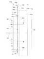
図2(A)及び2(B)は、各光変調装置60r,60g,60bの構成の一例を説明するための正面図及び側面図である。各光変調装置60r,60g,60bは、いずれも同様の構造を有しているため、ここでは、光変調装置60gを代表例として説明し、他のものの説明等は省略する。図3は、光変調装置60gによる光の処理を説明するための側面図である。光変調装置60gは、既述のように、液晶パネル61gと、光学補償板62gとを備える。また、図2(A)及び2(B)に示すように、光学補償板62gは、本体部分である光学補償素子63と、光学補償素子63を周囲から支持する保持枠であり外周枠である補償板フレーム部64とを有する。
2A and 2B are a front view and a side view for explaining an example of the configuration of each of the
補償板フレーム部64は、主要部分であるフレーム本体部64aと位置調整用の取手部64bとを備えている。フレーム本体部64a及び取手部64bは、金属材料やプラスチック等により製造されている。フレーム本体部64aは、液晶パネル61gの有効画素領域UAに略合わせた矩形の開口HPを有する枠体である。また、補償板フレーム部64は、光学補償素子63側(−Z側)に、アルミ蒸着等のミラー加工により平坦な表面を有する反射部64cを備えている。
The
光学補償素子63は、補償板フレーム部64の開口HPよりも若干大きなサイズであり、接着等によって補償板フレーム部64上に固定されている。光学補償板62gは、組付けられた状態において、図1のプロジェクター10の光学系全体を遮光した状態で収納するライトガイドであるケース部材11と液晶パネル61とに挟持されている。なお、図2(B)中に示すケース部材11の溝11aは、図1の偏光分離素子32gを組付けるためのものである。液晶パネル61gをネジ止め(不図示)等によりケース部材11に組付けることで、光学補償素子63も併せて固定される。光学補償板62gの固定に際しては、補償板フレーム部64の開口HPを画定する縁部分64dが、液晶パネル61g内における画像光の形成可能な領域である有効画素領域UAの外縁に略対向するように位置決めされる。
The
ここで、図2(A)に示す光変調装置60gに入射する光の被照明領域QAは、液晶パネル61gの有効画素領域UA内において一定以上の照度を確保すべく、ある程度のマージンをもって有効画素領域UAを覆うように設計されている。このため、光変調装置60gに入射する照明光には、液晶パネル61gの有効画素領域UAに入射して変調光を形成するような有効に利用される有用光だけでなく、例えば、有効画素領域UA外の周辺領域PAに入射する変調されることのない不要光LL(図3参照)のような成分も存在する。光変調装置60gでは、このような光の成分が画像投射に影響しないように、的確な処理が可能となっている。
Here, the illuminated area QA of the light incident on the
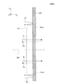
以下、図3を用いて、光変調装置60gによる照明光の処理動作について説明する。まず、光変調装置60gにおいて、光学補償素子63を経て液晶パネル61gの有効画素領域UAに入射する有用光(G光)である入射光ILは、液晶パネル61gの背面側で反射される際に、液晶パネル61内に電気的信号として入力された駆動信号或いは制御信号に応じて変調されて出射光OLとなる。この出射光OLは、光学補償素子63を再度経て出射される。以上において、図1の偏光分離素子32gを経たG光である入射光ILは、既述のように、P偏光の状態となっており、これに対して、出射光OLは、入射光ILとは異なる偏光であるS偏光の状態となって出射する。つまり、投射画像としての有用光は、光変調装置60gにP偏光の状態で入射してS偏光の状態で出射する。S偏光となった有用光(G光)は、図1の反射光学素子偏光分離素子32gにおいて反射され投射画像の成分として用いられる。一方、図3において、光変調装置60gに向かう照明光の成分のうち、有効画素領域UA外の周辺領域PAから入射しようとする不要光LLは、補償板フレーム部64上に設けられた平坦な反射部64cにより偏光状態が変化することなく反射される。ここで、不要光LLも、図1の偏光分離素子32gを経ているため、周辺領域PAに入射する際には、入射光ILと同じP偏光の状態となっている。しかし、不要光LLは、反射部64cにより偏光状態を変えられることなくP偏光状態のまま反射される。つまり、反射後の不要光LLは、光変調装置60gを経てS偏光状態となっている出射光OLとは偏光状態の異なるものとなっている。従って、反射後の不要光LLは、図1の偏光分離素子32gにおいて反射されない。これにより、有効画素領域UA外からの戻り光である反射後の不要光LLと、変調光即ち出射光OLとが分離可能となり、両者がともに投影画像として投射レンズ80により投射画像として投射されることを回避できる。
Hereinafter, the processing operation of the illumination light by the
本実施形態のプロジェクター10は、光変調装置60gのほか、光変調装置60r,60bも上記のような構造を有し、各光変調装置60r,60g,60bにおいて、補償板フレーム部64上の反射部64cが、液晶パネル61r,61g,61b周辺に入射する不要光LLをその偏光状態を維持したまま反射する偏光維持反射部として機能している。これにより、投射画像に含まれる漏れ光となることを抑制し、延いてはプロジェクター10の投射画像のコントラスト低下を抑制している。
In the
また、上記において、補償板フレーム部64のフレーム本体部64aは、矩形の開口HPを有する枠体構造としているが、これに限らず、たとえば、石英ガラス等の光透過性基板により形成される板状のものであっても構わない。この場合、光学補償板62gは、当該光透過性基板上に光学補償素子63を貼付けることで構成され、反射部64cは、光透過性基板上に貼付けられた光学補償素子63の周辺部分に沿って枠状に設けられることで偏光維持反射部として機能する。
In the above description, the
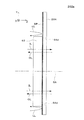
図4及び図5は、本実施形態の変形例のプロジェクターについて説明するための図であり、いずれも本変形例のプロジェクターに用いる光学補償板の側面図である。なお、本変形例では、光学補償板の補償板フレーム部以外の構成については、図1等に示すものと同様であるので、光学補償板以外の構成については、図示及び説明を省略する。 4 and 5 are diagrams for explaining a projector according to a modification of the present embodiment, both of which are side views of an optical compensator used in the projector according to the modification. In this modification, the configuration other than the compensation plate frame portion of the optical compensation plate is the same as that shown in FIG. 1 and the like, and therefore, illustration and description of the configuration other than the optical compensation plate are omitted.
図4に示す光学補償板162gは、光学補償素子63と、補償板フレーム部164とを有する。このうち、補償板フレーム部164は、高反射性を有する物質により形成されている。具体的な補償板フレーム部164の材料としては、例えばミロ材(商品名)が有用である。ここで、ミロ材とは、基材上に形成したアルミニウム層を真空蒸着の超反射層で被覆したものであり、全反射率95%程度の高い反射率を維持し、かつ、拡散率も低減されている部材である。ミロ材を用いて補償板フレーム部164を作製することにより、補償板フレーム部164の表面部分SPにおいてミラー加工をした場合と同様に不要光LLの偏光状態を維持させた反射が可能となる。なお、補償板フレーム部164は、主要部分を金属材料等により構成し、当該主要部分の表面をミロ材で覆うことで偏光維持反射部として機能させるという構成であってもよい。
The
また、図5に示す光学補償板262gは、補償板フレーム部264をアルミニウム等の金属材料で形成しており、補償板フレーム部264の光学補償素子63側の平坦な表面部分SPには、鏡面仕上げが施されている。この場合も、凹凸のない表面部分SPを鏡面に仕上げることで、不要光LLをその偏光状態を変えることなく反射させることができる。なお、光学補償板262gは、通常密閉された空間内に設置されており、表面が酸化して鏡面仕上げの状態が劣化するという可能性は低いと考えられる。但し、必要があれば表面をさらにコーティングしてもよい。なお、補償板フレーム部264は、アルミニウム等の金属材料に代えて研磨等の表面加工により高い光反射性を示すプラスチック材料を用いて作製してもよい。
Further, in the
〔第2実施形態〕
図6(A)及び6(B)は、第2実施形態に係るプロジェクターに用いる光学補償板の構成を概念的に説明する平面図である。本実施形態に係るプロジェクターでは、光学補償板362gにおいて不要光LLの偏光成分を吸収することで、不要光LLに起因して漏れ光や迷光が発生することを防止し、不要光LLに起因する投影画像のコントラスト低下を抑制している。なお、図6(A)及び6(B)に示す例は、図1等に示すプロジェクター10の変形例を説明するものであり、特に説明しない部分は、第1実施形態と同様である。
[Second Embodiment]
FIGS. 6A and 6B are plan views conceptually illustrating the configuration of the optical compensator used in the projector according to the second embodiment. In the projector according to the present embodiment, the
本実施形態において、光学補償板362gは、光学補償素子63と、補償板フレーム部364とを有し、このうち、補償板フレーム部364は、フレーム本体部64aと、有機偏光部材364b,364c,364d,364eとを有する。有機偏光部材364b〜364eは、いずれも同一の材料により形成されるシート状の吸収型の有機偏光フィルムであり、入射する光の成分のうち特定の偏光状態の成分を吸収する偏光吸収部として機能する。これら有機偏光部材364b〜364eは、フレーム本体部64aの光学補償素子63側の表面において、補償板フレーム部364の開口HPの形状を画定する縁部分64dに沿ってそれぞれ貼付けられている。この際、有機偏光部材364b〜364eの軸方向は、いずれも同一となっている。ここでは、図1の偏光分離素子32gを経た不要光LLの偏光状態はP偏光であるため、有機偏光部材364b〜364eの透過軸方向は、P偏光に対して垂直となる方向に合わせられている。これにより、不要光LLの成分が吸収され、漏れ光の発生を防ぐことができる。つまり、変調光の偏光状態と一致する成分が発生することを防止できる。なお、有機偏光部材364b〜364eの種類は適宜選択可能であり、必要な光の吸収量等に応じて消光比を適度なものとすることができる。
In the present embodiment, the
また、上記補償板フレーム部364では、フレーム本体部64a上に有機偏光部材364b〜364eを設けているが、有機偏光部材364b〜364eに代えて、植毛紙を貼付けることによっても光の吸収が可能である。植毛紙に入射した光は、植毛の側面で反射を繰り返しながら植毛の奥側へと進入し、吸収される。従って、黒色塗装によって遮光するのに比べ、種々の偏光状態の光を効率的に吸収することが可能となる。
Moreover, in the said compensation
〔第3実施形態〕
図7(A)は、第3実施形態に係るプロジェクターに用いる光学補償板の構成を概念的に説明する平面図であり、光学補償板の一部を拡大した図である。なお、図7(A)に示す例は、図1等に示すプロジェクター10の変形例を説明するものであり、特に説明しない部分は、第1実施形態と同様である。
[Third Embodiment]
FIG. 7A is a plan view conceptually illustrating the configuration of the optical compensation plate used in the projector according to the third embodiment, and is an enlarged view of a part of the optical compensation plate. Note that the example shown in FIG. 7A describes a modification of the
本実施形態において、光学補償板462gは、通常の偏光維持反射部である反射部64cに加え、補助的に偏光維持反射部として機能する第2反射部463dを光学補償素子463上に有している。光学補償板462gの光学補償素子463と補償板フレーム部64とは、両面テープ等の接着部GLにより、光学補償素子63の外縁部分において連続的又は間欠的に接着されている。接着部GLに不要光が入射すると、当該不要光が反射され、偏光状態が乱れてP偏光成分を有する漏れ光が生じる。これに対して、光学補償板462gでは、接着部GLに対応して、不要光の入射を防ぐべく光学補償素子463の表面上に第2反射部463dを形成している。第2反射部463dは、ミラー加工等により反射部64cと同様平坦な表面を有した状態に形成されている。これにより、接着部GL部分に向かう不要光LL2を第2反射部463dにより偏光状態を維持したまま反射させることができる。なお、光学補償素子63周辺に入射する不要光LL1は反射部64cにより偏光状態を維持したまま反射される。また、反射部64cに代えて、図6(A)及び6(B)に示した有機偏光部材364b〜364eを貼付けることにより、不要光LL1を吸収させ、偏光吸収部として機能させるものとしてもよい。
In the present embodiment, the
なお、図7(B)に示す光学補償板562gように、光学補償素子62aの位置と補償板フレーム部564の位置とを入替え可能な場合には、補償板フレーム部564の反射部564cを光学補償素子462aのある面と反対側の面上に形成することで、光学補償素子63周辺に入射する不要光LL1と接着部GL部分に向かう不要光LL2との双方を反射させることが可能である。光学補償素子の位置と補償板フレーム部の位置とを入替えについては、上記したその他の各実施形態においても同様に可能である。
7B, when the position of the optical compensation element 62a and the position of the compensation
〔第4実施形態〕
図8(A)及び8(B)は、第4実施形態に係るプロジェクターに用いる光変調装置の構成を概念的に説明する図であり、図8(A)は、液晶パネル661gの正面図であり、図8(B)は、液晶パネル661gを含む光変調装置660gの側面図である。なお、図8(A)及び8(B)に示す例は、図1等に示すプロジェクター10の変形例を説明するものであり、特に説明しない部分は、第1実施形態と同様である。
[Fourth Embodiment]
8A and 8B are diagrams for conceptually explaining the configuration of the light modulation device used in the projector according to the fourth embodiment, and FIG. 8A is a front view of the
本実施形態において、光変調装置660gの液晶パネル661gは、液晶パネル前面枠661a上に偏光維持反射部である反射部664cを有している。反射部664cは、液晶パネル前面枠661aによって画定される液晶パネル661gのパネル領域EAに沿う縁部分664dを有する矩形状の開口HBを有して配置されている。また、反射部664cは、少なくとも、被照明領域QAのうちパネル領域EA外の領域である見切り部分MAを覆うものとなっている。反射部664cは、金属材料や有機材料の表面上に凹凸の無いミラー加工がなされたものであるか、金属材料や有機材料の表面を鏡面仕上げしたもの、或いはミロ材により形成されたものである。なお、パネル領域EAのうち有効画素領域UA外にわずかに形成される縁領域は、画像として使用されることのない所謂ダミー用の画素部分であり、通常は黒表示となるように設計されており、光成分を反射することがなく、投影画像に影響を与えないものとなっている。ここで、光学補償板62gの補償板フレーム部64のサイズが、有効画素領域UA内において一定以上の照度を確保すべく、若干大きめに設計されていると、一部の不要光LL3が、光学補償素子63を介して液晶パネル661gの見切り部分MAに入り込むことがある。これに対して、反射部664cは、入射する不要光LL3をその偏光状態を維持したまま反射する。つまり、反射部664cが偏光維持反射部として機能することで不要光LL3の処理がなされる。また、反射部664cに代えて、図6(A)及び6(B)に示した有機偏光部材364b〜364eを貼付けて、不要光LL3を吸収する偏光吸収部として機能させてもよい。
In the present embodiment, the
以上実施形態に即して本発明を説明したが、本発明は、上記の実施形態に限られるものではなく、その要旨を逸脱しない範囲において種々の態様において実施することが可能であり、例えば次のような変形も可能である。 Although the present invention has been described based on the above embodiments, the present invention is not limited to the above-described embodiments, and can be implemented in various modes without departing from the gist thereof. Such modifications are also possible.
まず、上記実施形態では、偏光分離素子32r,32g,32bを通過したP偏光を液晶パネル61r,61g,61bに入射させ、偏光分離素子32r,32g,32bで反射されたS偏光を画像光として出射する例のみを挙げたが、偏光分離素子32r,32g,32bで例えば反射されたS偏光を液晶パネル61r,61g,61bに入射させ、偏光分離素子32r,32g,32bを例えば通過したP偏光を画像光として出射するタイプとすることもできる。
First, in the above embodiment, the P-polarized light that has passed through the
また、上記実施形態では、いずれも所謂反射型の液晶パネルを用いたプロジェクターについてのものであるが、光変調において光を透過する透過型の液晶パネルを用いたプロジェクターにおいて、例えば当該液晶パネルの光路前段に設置される光学補償板や、当該液晶パネルを構成する前面枠に、偏光維持反射部や偏光吸収部を設けることで、迷光防止を行うことができる。 Further, in the above-described embodiments, each is a projector using a so-called reflective liquid crystal panel. However, in a projector using a transmissive liquid crystal panel that transmits light in light modulation, for example, the optical path of the liquid crystal panel. Stray light can be prevented by providing a polarization maintaining reflection unit and a polarization absorption unit on the optical compensator installed in the previous stage and the front frame constituting the liquid crystal panel.
また、上記実施形態のプロジェクター10では、光源装置21を、光源ランプ21a、一対のフライアイ光学系21d,21e、偏光変換部材21g、及び重畳レンズ21iで構成したが、フライアイ光学系21d,21e、偏光変換部材21g等については省略することができ、光源ランプ21aも、超高圧水銀ランプ、メタルハライドランプ、LED(発光ダイオード)等の別光源に置き換えることができる。
In the
また、上記実施形態のプロジェクター10では、各色の液晶パネル61r,61g,61bをそれぞれの面内を均一な明るさで照明するようにフライアイ光学系21d,21e、と重畳レンズ21iを用いていたが、それらに代わってインテグレータロッド光学系を用いることができる。
In the
また、上記実施形態では、色分離導光光学系23を用いて光源光の色分離を行って、光変調部25において各色の変調を行った後に、クロスダイクロイックプリズム27において各色の像の合成を行っているが、単一の液晶パネルすなわちライトバルブによって画像を形成することもできる。
In the above embodiment, the color separation of the light source light is performed using the color separation light guide
上記実施形態では、3つの液晶パネル61r,61g,61bを用いたプロジェクター10の例のみを挙げたが、本発明は、2つの液晶パネルを用いたプロジェクター、あるいは、4つ以上の液晶パネルを用いたプロジェクターにも適用可能である。
In the above embodiment, only the example of the
上記実施形態のプロジェクター10は、スクリーンを観察する方向から投射を行なうフロントタイプのプロジェクターのみならず、スクリーンを観察する方向とは反対側から投射を行なうリアタイプのプロジェクターとしても使用できる。
The
10…プロジェクター、 21…光源装置、 23…色分離導光光学系、 25…光変調部、 32r,32g,32b…偏光分離素子、 27…クロスダイクロイックプリズム、 29…投射レンズ、 60r,60g,60b,660g…光変調装置、 61r,61g,61b,661g…液晶パネル、 62r,62g,62b,162g,262g,362g,462g,562g…光学補償板、 63…光学補償素子、 64…補償板フレーム部、 64c,664c…反射部、 364b,364c,364d,364e…有機偏光部材、 64d,664d…縁部分、 HP,HB…開口、 SP…表面部分、 QA…被照明領域、 UA…有効画素領域、 PA…周辺領域、 EA…パネル領域、 GL…接着部、 IL…入射光、 OL…出射光、 LL,LL1,LL2,LL3…不要光、 SA…システム光軸
DESCRIPTION OF
Claims (10)
前記光変調素子内における有効画素領域の外縁に沿って設けられ、入射する光の偏光状態を維持したまま反射する平坦面を含む偏光維持反射部と
を備えるプロジェクター。 A light modulator that changes the polarization state of the incident light; and
And a polarization maintaining / reflecting unit including a flat surface that is provided along an outer edge of the effective pixel region in the light modulation element and reflects the polarization state of incident light while maintaining the polarization state.
前記光変調素子内における有効画素領域の外縁に沿って設けられ、入射する光の成分のうち特定の偏光状態の成分を吸収する偏光吸収部と
を備えるプロジェクター。 A light modulator that changes the polarization state of the incident light; and
A projector comprising: a polarization absorption unit that is provided along an outer edge of an effective pixel region in the light modulation element and that absorbs a component of a specific polarization state among incident light components.
前記光変調素子に入射した光の第1方向及び第2方向のうちいずれか一方の偏光を透過させ、他方の偏光を反射する偏光分離素子をさらに備える、請求項1又は請求項2に記載のプロジェクター。 The light modulation element is a reflective liquid crystal panel,
3. The polarization separation element according to claim 1, further comprising a polarization separation element that transmits one of the polarized light in the first direction and the second direction of the light incident on the light modulation element and reflects the other polarized light. projector.
前記偏光維持反射部又は前記偏光吸収部は、前記補償板フレーム部に形成されている、請求項1から請求項3までのいずれか一項に記載のプロジェクター。 An optical compensation plate for compensating a polarization state of light incident on the light modulation element; and a compensation plate frame portion surrounding and supporting the optical compensation plate along an outer edge of an effective pixel region of the light modulation element. Have
The projector according to any one of claims 1 to 3, wherein the polarization maintaining reflection unit or the polarization absorption unit is formed in the compensation plate frame unit.
Priority Applications (2)
| Application Number | Priority Date | Filing Date | Title |
|---|---|---|---|
| JP2009075939A JP2010230802A (en) | 2009-03-26 | 2009-03-26 | Projector |
| US12/730,760 US20100245689A1 (en) | 2009-03-26 | 2010-03-24 | Projector |
Applications Claiming Priority (1)
| Application Number | Priority Date | Filing Date | Title |
|---|---|---|---|
| JP2009075939A JP2010230802A (en) | 2009-03-26 | 2009-03-26 | Projector |
Publications (2)
| Publication Number | Publication Date |
|---|---|
| JP2010230802A true JP2010230802A (en) | 2010-10-14 |
| JP2010230802A5 JP2010230802A5 (en) | 2012-01-19 |
Family
ID=42783747
Family Applications (1)
| Application Number | Title | Priority Date | Filing Date |
|---|---|---|---|
| JP2009075939A Withdrawn JP2010230802A (en) | 2009-03-26 | 2009-03-26 | Projector |
Country Status (2)
| Country | Link |
|---|---|
| US (1) | US20100245689A1 (en) |
| JP (1) | JP2010230802A (en) |
Cited By (1)
| Publication number | Priority date | Publication date | Assignee | Title |
|---|---|---|---|---|
| JP2013003527A (en) * | 2011-06-21 | 2013-01-07 | Citizen Finetech Miyota Co Ltd | Reflection type liquid crystal display device |
Families Citing this family (3)
| Publication number | Priority date | Publication date | Assignee | Title |
|---|---|---|---|---|
| JP5170207B2 (en) * | 2010-10-20 | 2013-03-27 | 株式会社Jvcケンウッド | Distributed compensator and projection liquid crystal display |
| US10656497B1 (en) | 2019-02-06 | 2020-05-19 | The Government Of The United States As Represented By The Secretary Of The Air Force | Polarization scene projector |
| JP2022021962A (en) * | 2020-07-23 | 2022-02-03 | セイコーエプソン株式会社 | Liquid crystal device and electronic apparatus |
Citations (3)
| Publication number | Priority date | Publication date | Assignee | Title |
|---|---|---|---|---|
| JP2002014299A (en) * | 2000-04-25 | 2002-01-18 | Mitsubishi Electric Corp | Illuminating device and projection type display device |
| JP2002131688A (en) * | 2000-10-26 | 2002-05-09 | Nec Viewtechnology Ltd | Aperture and projector device using the same |
| JP2009008887A (en) * | 2007-06-28 | 2009-01-15 | Sony Corp | Optical part, optical unit, and display device |
Family Cites Families (4)
| Publication number | Priority date | Publication date | Assignee | Title |
|---|---|---|---|---|
| US7188954B2 (en) * | 2003-03-14 | 2007-03-13 | Victor Company Of Japan Limited | Image displaying apparatus and color separating-combining optical system |
| JP2006350291A (en) * | 2005-05-17 | 2006-12-28 | Seiko Epson Corp | Liquid crystal projector |
| US7475991B2 (en) * | 2005-12-22 | 2009-01-13 | 3M Innovative Properties Company | Polarizing beamsplitter assembly |
| JP5098681B2 (en) * | 2008-02-15 | 2012-12-12 | セイコーエプソン株式会社 | Liquid crystal device, projection device, and electronic apparatus |
-
2009
- 2009-03-26 JP JP2009075939A patent/JP2010230802A/en not_active Withdrawn
-
2010
- 2010-03-24 US US12/730,760 patent/US20100245689A1/en not_active Abandoned
Patent Citations (3)
| Publication number | Priority date | Publication date | Assignee | Title |
|---|---|---|---|---|
| JP2002014299A (en) * | 2000-04-25 | 2002-01-18 | Mitsubishi Electric Corp | Illuminating device and projection type display device |
| JP2002131688A (en) * | 2000-10-26 | 2002-05-09 | Nec Viewtechnology Ltd | Aperture and projector device using the same |
| JP2009008887A (en) * | 2007-06-28 | 2009-01-15 | Sony Corp | Optical part, optical unit, and display device |
Cited By (1)
| Publication number | Priority date | Publication date | Assignee | Title |
|---|---|---|---|---|
| JP2013003527A (en) * | 2011-06-21 | 2013-01-07 | Citizen Finetech Miyota Co Ltd | Reflection type liquid crystal display device |
Also Published As
| Publication number | Publication date |
|---|---|
| US20100245689A1 (en) | 2010-09-30 |
Similar Documents
| Publication | Publication Date | Title |
|---|---|---|
| US9389427B2 (en) | Optical system and projection display apparatus using the same | |
| US20210116698A1 (en) | Phosphor wheel device | |
| US8025409B2 (en) | Optical apparatus and projection display system | |
| JP5953835B2 (en) | projector | |
| US11669001B2 (en) | Projection display system | |
| JP2003270636A (en) | Liquid crystal panel, liquid crystal device, and projector using liquid crystal device | |
| US20120092625A1 (en) | Projector | |
| JP2010230802A (en) | Projector | |
| WO2021132059A1 (en) | Illumination device and display device | |
| JP2010152268A (en) | Liquid crystal display device and projector | |
| JP2012145740A (en) | Projector | |
| CN113544574A (en) | Optical element and projection display device | |
| JP2012018293A (en) | Projector | |
| JP2010113186A (en) | Projection type display device | |
| JP2010217360A (en) | Projector | |
| JP2007264245A (en) | Image projector | |
| JP2007206141A (en) | Projector | |
| JP6919165B2 (en) | projector | |
| JP4806912B2 (en) | Image projection device | |
| JP2009288387A (en) | Projection type display device | |
| JP2013105062A (en) | Light modulator, and projector | |
| JP2023114911A (en) | projector | |
| JP2010217652A (en) | Projector | |
| JP2006053430A (en) | Projector | |
| JP2008139812A (en) | Adjusting device and method for optical components constituting projector |
Legal Events
| Date | Code | Title | Description |
|---|---|---|---|
| A521 | Written amendment |
Free format text: JAPANESE INTERMEDIATE CODE: A523 Effective date: 20111125 |
|
| A621 | Written request for application examination |
Free format text: JAPANESE INTERMEDIATE CODE: A621 Effective date: 20111125 |
|
| A977 | Report on retrieval |
Free format text: JAPANESE INTERMEDIATE CODE: A971007 Effective date: 20121114 |
|
| A131 | Notification of reasons for refusal |
Free format text: JAPANESE INTERMEDIATE CODE: A131 Effective date: 20130108 |
|
| A761 | Written withdrawal of application |
Free format text: JAPANESE INTERMEDIATE CODE: A761 Effective date: 20130206 |