JP2010203145A - Floor supporting vibration absorber and floor structure - Google Patents
Floor supporting vibration absorber and floor structure Download PDFInfo
- Publication number
- JP2010203145A JP2010203145A JP2009049681A JP2009049681A JP2010203145A JP 2010203145 A JP2010203145 A JP 2010203145A JP 2009049681 A JP2009049681 A JP 2009049681A JP 2009049681 A JP2009049681 A JP 2009049681A JP 2010203145 A JP2010203145 A JP 2010203145A
- Authority
- JP
- Japan
- Prior art keywords
- floor
- elastic member
- support
- vibration absorber
- mass body
- Prior art date
- Legal status (The legal status is an assumption and is not a legal conclusion. Google has not performed a legal analysis and makes no representation as to the accuracy of the status listed.)
- Pending
Links
- 239000006096 absorbing agent Substances 0.000 title claims abstract description 50
- 239000000463 material Substances 0.000 claims description 47
- 238000009408 flooring Methods 0.000 claims description 15
- 230000005489 elastic deformation Effects 0.000 claims description 6
- 238000009413 insulation Methods 0.000 abstract description 4
- 238000013016 damping Methods 0.000 description 12
- 230000004048 modification Effects 0.000 description 7
- 238000012986 modification Methods 0.000 description 7
- 230000002238 attenuated effect Effects 0.000 description 4
- 238000009434 installation Methods 0.000 description 4
- XEEYBQQBJWHFJM-UHFFFAOYSA-N Iron Chemical compound [Fe] XEEYBQQBJWHFJM-UHFFFAOYSA-N 0.000 description 2
- 230000000694 effects Effects 0.000 description 2
- 238000000034 method Methods 0.000 description 2
- 230000002093 peripheral effect Effects 0.000 description 2
- 230000002787 reinforcement Effects 0.000 description 2
- 238000010521 absorption reaction Methods 0.000 description 1
- 230000000903 blocking effect Effects 0.000 description 1
- 238000010276 construction Methods 0.000 description 1
- 239000012530 fluid Substances 0.000 description 1
- 229910052742 iron Inorganic materials 0.000 description 1
- 230000009191 jumping Effects 0.000 description 1
- 239000002184 metal Substances 0.000 description 1
- 229910052751 metal Inorganic materials 0.000 description 1
- 239000002245 particle Substances 0.000 description 1
- 230000000149 penetrating effect Effects 0.000 description 1
- 238000007790 scraping Methods 0.000 description 1
- 239000007787 solid Substances 0.000 description 1
Images




Landscapes
- Floor Finish (AREA)
Abstract
Description
本発明は、二重床の床材を支持する床支持吸振具、この床支持吸振具を用いた床構造に関する。 The present invention relates to a floor-supported vibration absorber that supports a floor material of a double floor, and a floor structure using the floor-supported vibration absorber.
床構造においては、床衝撃音の遮断性能を向上させるために、支持部材を介して床基盤上から所定の高さに床を設ける二重床構造とする場合がある。このような二重床構造では、例えば、特許文献1に記載のように、弾性体と質量体を用いて床からの振動を減衰させる技術が開示されている。 In the floor structure, there is a case where a double floor structure is provided in which a floor is provided at a predetermined height from the floor base via a support member in order to improve the performance of blocking floor impact sound. In such a double floor structure, for example, as described in Patent Document 1, a technique for attenuating vibration from the floor using an elastic body and a mass body is disclosed.
特許文献1に記載の床構造によれば、床からの振動を効果的に減衰させることができる。しかしながら、特許文献1の床支持具は、第1弾性部材と第2弾性部材とが直列に配置されているため、床支持具の高さが高くなり、低床への対応には限界がある。また、特許文献1の床支持具では、第1弾性部材、第2弾性部材、質量体、受け材、支持ボルトなどを組み付けた後に現場施工を行っているため、床の固有振動周波数にあわせて施工後に調整を行うことは難しい。 According to the floor structure described in Patent Document 1, vibration from the floor can be effectively damped. However, in the floor support of Patent Document 1, since the first elastic member and the second elastic member are arranged in series, the height of the floor support becomes high, and there is a limit to dealing with a low floor. . Moreover, in the floor support tool of patent document 1, since it constructs on site after attaching a 1st elastic member, a 2nd elastic member, a mass body, a receiving material, a support bolt, etc., according to the natural vibration frequency of a floor. It is difficult to make adjustments after construction.
本発明は、上記事実を考慮してなされたものであり、床衝撃音の遮断性能が良好となると共に、全体の高さを低くでき、制振周波数の調整を容易に行うことの可能な床支持吸振具、及び、床構造を提供することを課題とする。 The present invention has been made in consideration of the above-mentioned facts. The floor impact sound can be cut off satisfactorily, the overall height can be lowered, and the damping frequency can be easily adjusted. It is an object to provide a support vibration absorber and a floor structure.
請求項1に記載する本発明の床支持吸振具は、床スラブ上に配置され、弾性変形可能であって振動を減衰させる第1弾性部材と、前記第1弾性部材上に支持され、前記床スラブとの間に間隔をもって配置される床材へ向かって立設され、前記床材を支持する支持部材と、前記床材の下側に取り付けられて前記床スラブと近づく方向へ延出され、弾性変形可能な第2弾性部材と、前記第2弾性部材の先端部に支持され前記第2弾性部材の弾性変形によって変位して振動を減衰させる質量体と、を備えている。 A floor-supporting vibration absorber of the present invention described in claim 1 is disposed on a floor slab, is elastically deformable and damps vibrations, is supported on the first elastic member, and the floor It is erected toward a flooring disposed with a gap between the slab, a support member that supports the flooring, and is attached to the lower side of the flooring and extends in a direction approaching the floor slab, A second elastic member that can be elastically deformed; and a mass body that is supported by a distal end portion of the second elastic member and is displaced by elastic deformation of the second elastic member to attenuate vibrations.
請求項1に記載する床支持吸振具によれば、床材に振動が加わった場合、この振動は、第2弾性部材へ伝わる。これによって、第2弾性部材が弾性変形して質量体が振動を吸収するように上下動することで、床材から床スラブへの振動を減衰する。減衰された振動は第1弾性部材によって減衰されて床スラブへ伝わるので、床衝撃音が良好に遮断される。 According to the floor support vibration damping device described in claim 1, when vibration is applied to the floor material, the vibration is transmitted to the second elastic member. Thus, the vibration from the floor material to the floor slab is attenuated by the second elastic member moving up and down so that the mass body absorbs vibration by elastic deformation. Since the damped vibration is attenuated by the first elastic member and transmitted to the floor slab, the floor impact sound is well blocked.
また、第2弾性部材は、床材の下側に取り付けられているので、第1弾性部材と直列配置する必要がなく、床支持吸振具の高さを低くすることができる。 Moreover, since the 2nd elastic member is attached to the lower side of a flooring, it is not necessary to arrange | position in series with a 1st elastic member, and can make the height of a floor support vibration absorber low.
また、質量体は、第2弾性部材の先端部に支持されているので、容易に質量体の重さを変えて、制振周波数の調整を行うことができる。 Moreover, since the mass body is supported by the front-end | tip part of a 2nd elastic member, the weight of a mass body can be changed easily and a damping frequency can be adjusted.
請求項2に記載する床支持吸振具は、前記支持部材と前記床材との間に、前記支持部材が取り付けられると共に前記床材を支持する受材が配置され、前記第2弾性部材は、前記受材に取り付けられていること、を特徴とする。 The floor supporting vibration absorber according to claim 2, wherein the support member is attached and a receiving material supporting the floor material is disposed between the support member and the floor material, and the second elastic member is It is attached to the said receiving material, It is characterized by the above-mentioned.
このように、受材で床材を受け、この受材に第2弾性部材を取り付けることにより、第2弾性部材を支持部材と接近した位置に配置でき、効果的に振動を減衰させることができる。 Thus, by receiving the flooring with the receiving material and attaching the second elastic member to the receiving material, the second elastic member can be disposed at a position close to the support member, and the vibration can be effectively damped. .
請求項3に記載する床支持吸振具は、前記第2弾性部材が、前記支持部材と離間した位置で前記床材の下面に取り付けられていること、を特徴とする。 The floor supporting vibration absorber described in claim 3 is characterized in that the second elastic member is attached to the lower surface of the flooring material at a position separated from the supporting member.
このように、前記第2弾性部材を支持部材と離間した位置に配置することにより、第1弾性部材、支持部材と、第2弾性部材、質量体とを、容易に並列的に配置することができる。 Thus, by arranging the second elastic member at a position separated from the support member, the first elastic member, the support member, the second elastic member, and the mass body can be easily arranged in parallel. it can.
請求項4に記載する床構造は、床スラブと、前記床スラブと間隔をもって配置される床材と、請求項1〜3のいずれか1項に記載の床支持吸振具と、を備えている。 The floor structure described in claim 4 is provided with a floor slab, a floor material arranged with an interval from the floor slab, and the floor support vibration absorber according to any one of claims 1 to 3. .
本発明の床構造によれば、床衝撃音を良好に遮断することができると共に、全体の高さを低くでき、制振周波数の調整を容易に行うことができる。 According to the floor structure of the present invention, floor impact sound can be satisfactorily blocked, the overall height can be lowered, and the damping frequency can be easily adjusted.
以上説明したように、本発明の床支持吸振具、及び、床構造によれば、床衝撃音を良好に遮断することができると共に、全体の高さを低くでき、制振周波数の調整を容易に行うことができる。 As described above, according to the floor supporting vibration absorber and the floor structure of the present invention, it is possible to satisfactorily cut off the floor impact sound, reduce the overall height, and easily adjust the damping frequency. Can be done.
[第1実施形態] [First Embodiment]
本発明における床支持吸振具、及び、この床支持吸振具が適用される床構造の実施形態を図面に基づき説明する。なお、図中の矢印UPは床構造における上方向を示す。 An embodiment of a floor support vibration absorber according to the present invention and a floor structure to which the floor support vibration absorber is applied will be described with reference to the drawings. In addition, arrow UP in a figure shows the upward direction in a floor structure.
図1に示される床構造10は、主に集合住宅に用いられる二重床(乾式遮音二重床)の構造であり、上階で発せられて階下に伝播する床衝撃音(歩行音、物の落下音、子供の飛び跳ね等)を低減させるための構造である。
A
(床構造及び床支持吸振具の構成) (Floor structure and floor support vibration absorber configuration)
図1に示されるように、床構造10は、躯体床となるコンクリート製の床スラブ12と上床材14との間に、所定の間隔で複数本並べられた床支持吸振具16を介在させており、床支持吸振具16の介在によって床スラブ12と上床材14との間に空間を形成して遮音効果を得る状態としている。
As shown in FIG. 1, the
なお、本実施形態の上床材14は、下地パネル14Aを備えると共に、下地パネル14A上に捨張材14Bを設け、その上にさらに仕上げ材14Cを設けた積層構造となっている。ここで、仕上げ材14Cを除いた上床材14(下地パネル14A及び捨張材14B)、及び、床支持吸振具16、が床下地材である。
Note that the
なお、捨張材14Bは、必ずしも必要ではなく、捨張材14Bを除いた構成とすることもできる。
In addition, the discarding
図2には、下地パネル14Aへの床支持吸振具16の配置図が示されている。下地パネル14Aは、各々、所定間隔の隙間(以下「目地Mという」)が構成されるように敷設されている。目地Mは、下地パネル14A同士の接触による軋み音などを防止するために、10mm〜20mm程度の間隔とされている。床支持吸振具16は、目地Mを跨ぐようにして配置されている。
FIG. 2 shows a layout of the floor support vibration absorber 16 on the
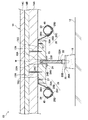
図3に示されるように、床支持吸振具16は、第1弾性部材としてのクッションゴム18、支持部材としての支持ボルト22、受材としての支持パネル15、第2弾性部材26、及び質量体40を備えている。
As shown in FIG. 3, the floor support vibration absorber 16 includes a
クッションゴム18は、床スラブ12上に配置されている。クッションゴム18は、円筒状とされており、上床材14からの振動を減衰させるために、床スラブ12上に支持されるものであり、弾性変形可能とされている。
The
クッションゴム18上には、中間受け部としての中間受け部材20を介して支持ボルト22が直立状態で支持されている。中間受け部材20は、円筒状とされて中間部にフランジ部20Aを備え、円筒部の一方側がクッションゴム18の筒内側に挿入されると共にフランジ部20Aの下面(クッションゴム18側へ向けられた面)がクッションゴム18の上面(床スラブ12側の面と反対側の面)に固着されている。中間受け部材20の円筒部内周面には、雌ネジ部20Bが形成され、この雌ネジ部20Bには、支持ボルト22の軸部に形成された雄ネジ部22Aが螺合される。これにより、中間受け部材20が支持ボルト22に一体化される。
On the
下地パネル14Aの下側には、下地パネル14Aを支持するように支持パネル15が配置されている。支持パネル15は、下地パネル14Aの上面からねじ15Nによりねじ止めされている。支持パネル15は正方形板状とされ、中央部に調整孔15Aが構成されている。
A
支持ボルト22は、クッションゴム18と反対側、すなわち、床スラブ12と反対方向へ延びて、パネル受け部材24及び支持パネル15を介して上床材14を支持している。パネル受け部材24は、円筒状の円筒部24Bと、円筒部24Bの一方の開口部から外側へ向けて突き出した鍔部24Aを備える。パネル受け部材24の円筒部24Bは、支持パネル15の調整孔15A内に挿入されて固着され、鍔部24Aの上面(上床材14側へ向けられた面)が支持パネル15の下面(床スラブ12と対向する側の面)に固着される。パネル受け部材24の円筒部内周面には、雌ネジ部24Cが形成され、この雌ネジ部24Cには、支持ボルト22の軸部に形成された雄ネジ部22Bが螺合される。これらにより、上床材14は、床スラブ12との間に間隔をもって配置される。
The
支持ボルト22の先端部には、マイナスドライバを差し込むための凹部22Hが形成されており、上床材14の下地パネル14Aに捨張材14B、仕上げ材14Cが敷設される前の状態において、マイナスドライバを支持ボルト22の凹部22Hに差し込んで支持ボルト22を回転させることによって、床スラブ12からの下地パネル14Aの高さを調節することができるようになっている。
A
支持パネル15の上面の対向する2つの端部には、段部15Dが構成されている。段部15Dの各々には、第2弾性部材26が取り付けられる。第2弾性部材26は、板バネで構成され、取付部26A、腕部26B、及び、先端部26Cを有している。
取付部26Aは、第2弾性部材26の一端部に形成され、支持パネル15の段部15Dに配置されている。取付部26Aは、ねじ27により、支持パネル15に固定されている。腕部26Bは、取付部26Aと連続され、支持パネル15の端部から斜め下方向(床スラブ12と近づく方向)に延出されている。先端部26Cは、腕部26Bと連続され、斜め上方向に屈曲して凹部26Dを構成している。凹部26Dを挟んで両側には、鈎状の止め部26Eが設けられている。
The
第2弾性部材26の凹部26Dには、質量体40が配置され、質量体40は先端部26Cに支持されている。質量体40の外形は、凹部26Dに沿った形状とされており、質量体40は、凹部26Dに載置され、2つの止め部26Eに引っ掛けて架け渡された取付バンド28により上側が押さえられて、先端部26Cに取り付けられている。
The
質量体40としては、鉄などの金属塊、流体や固体粒子などを収容した容器、その他、質量を確保できるあらゆるものを用いることができる。
As the
質量体40は、第2弾性部材26の弾性変形によって変位して上床材14からの振動を減衰させるようになっており、第2弾性部材26及び質量体40は、上床材14から床スラブ12への振動に対して動吸振器として機能する。
The
(作用) (Function)
次に、上記の実施形態の作用を説明する。 Next, the operation of the above embodiment will be described.
上階で発せられた床衝撃音(例えば、歩行音等)の振動は、上床材14から第2弾性部材26へ伝わる。これによって、第2弾性部材26が弾性変形し、質量体40が振動を吸収するように上下動することで、振動を減衰させる。さらに、減衰された振動が支持ボルト22を介してクッションゴム18へ伝わる。減衰された振動は、さらにクッションゴム18によって減衰されて床スラブ12へ伝わる。このため、床衝撃音が良好に遮断される。
The vibration of floor impact sound (for example, walking sound) generated on the upper floor is transmitted from the
本実施形態によれば、第2弾性部材26が床材の下側に取り付けられていて、クッションゴム18と直列配置されていないので、床支持吸振具16の高さを低くすることができる。
According to this embodiment, since the second
また、質量体40は、第2弾性部材26の先端部26Cに支持されているので、設置後に容易に質量体40の取り替えを行うことができる。したがって、設置後に、質量体40の重さを変えるなどにより、容易に制振周波数の調整を行うことができる。
Moreover, since the
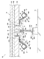
なお、本実施形態では、第2弾性部材26を支持パネル15の上面側の段部15Dに取り付けたが、図4に示すように、第2弾性部材26は支持パネル15の下面側に取り付けてもよい。
In the present embodiment, the second
また、第2弾性部材26は支持パネル15の一端のみに1つ取り付けてもよいし、3個以上取り付けてもよい。
One second
また、本実施形態では、取付バンド28を止め部26Eに引っ掛けて質量体40を押さえることにより先端部26Cに質量体40を取り付けたが、質量体40の取り付けは、他の方法で行ってもよい。例えば、図5に示すように、第2弾性部材26の中間部に孔26Hを穿孔し、面ファスナー29を巻回して取り付けることもできる。
In the present embodiment, the
また、本実施形態では、第2弾性部材26を板バネで構成したが、第2弾性部材は板バネに限定されず、例えば、図6に示すように、ゴム板36で構成することもできる。この場合においても、ゴム板36の断面形状は、第2弾性部材26と同様とし、第2弾性部材26の取付部26A、腕部26B、先端部26Cに対応する部分を、各々、取付部36A、腕部36B、先端部36Cとすればよい。なお、ゴム板36を用いる場合には、補強のために、帆布37をゴム板36内に埋め込んでおくことが好ましい。
Moreover, in this embodiment, although the 2nd
また、本実施形態では、第2弾性部材26が、2分割されて1つの支持パネル15に支持されている例について説明したが、図7に示すように、2つの第2弾性部材26が一体となった第2弾性部材46としてもよい。この場合には、支持パネル15に段部15Dを構成せず、取付部26Aを支持パネル15と下地パネル14Aとの間に挟み込んで、支持パネル15用のねじ15Nで第2弾性部材26を取り付けることができる。
In the present embodiment, the example in which the second
また、本実施形態では、支持パネル15を介して上床材14を支持したが、支持パネル15は必ずしも必要ではなく、図8に示すように、支持パネル15を省略し支持ボルト22を直接下地パネル14Aに取り付け、第2弾性部材26も直接下地パネル14Aに取り付けてもよい。この場合の床支持吸振具16の配置は、図9に示すように、目地Mを跨がない位置、例えば、下地パネル14Aの中央部と四つの角の位置とすることができる。そして、下地パネル14Aには、調整孔15Aに対応する位置に、厚み方向に貫通された調整孔14Hを構成する。
In the present embodiment, the
[第2実施形態] [Second Embodiment]
次に、本発明の第2実施形態について説明する。本実施形態では、第1実施形態と同様の部分については同一の符号を付して、その詳細な説明は省略する。 Next, a second embodiment of the present invention will be described. In the present embodiment, the same parts as those in the first embodiment are denoted by the same reference numerals, and detailed description thereof is omitted.
図10に示されるように、本実施形態の床構造60は、躯体床となるコンクリート製の床スラブ12と上床材14との間に、所定の間隔で複数本並べられた床支持具62及び動吸振器64を介在させており、床支持具62及び動吸振器64の介在によって床スラブ12と上床材14との間に空間を形成して遮音効果を得る状態としている。本実施形態の床構造60では、床支持具62及び動吸振器64により床支持吸振具61が構成されている。
As shown in FIG. 10, the floor structure 60 of the present embodiment includes a
図11には、下地パネル14Aと、床支持具62及び動吸振器64の配置図が示されている。床支持具62は、目地Mを跨ぐようにして配置されている。動吸振器64は、図11(A)に示すように、下地パネル14Aの短手方向の中央部で床支持具62の中間部に所定間隔で配置してもよいし、図11(B)に示すように、短手方向の両端部で床支持具62の近傍に所定間隔で配置してもよい。
FIG. 11 shows a layout of the
図12に示すように、動吸振器64は、第2弾性部材46、及び、質量体40を備えている。第2弾性部材46は、板バネで構成され、取付部46A、腕部46B、及び、先端部46Cを有している。
As shown in FIG. 12, the
取付部46Aは、第2弾性部材46の中間部に形成され、下地パネル14Aにねじ15Tにより固定されている。腕部46Bは、取付部46Aの両端部の外側に連続され、下地パネル14Aから斜め下方向(床スラブ12と近づく方向)に延出されている。先端部46Cは、2つの腕部46Bと各々連続され、斜め上方向に屈曲して凹部46Dを構成している。凹部46Dを挟んで両側には、鈎状の止め部26Eが設けられている。
The
第2弾性部材46の凹部46Dには、質量体40が配置され、質量体40は先端部46Cに支持されている。質量体40の外形は、凹部46Dに沿った形状とされており、質量体40は、凹部46Dに載置され、2つの止め部26Eに引っ掛けて架け渡された取付バンド28により上側が押さえられて、先端部46Cに取り付けられている。
The
質量体40は、第2弾性部材46の弾性変形によって変位して上床材14からの振動を減衰させるようになっており、第2弾性部材46及び質量体40は、上床材14から床スラブ12への振動に対して動吸振器として機能する。
The
床支持具62は、支持パネル15、クッションゴム18、及び、支持ボルト22を備えている。これらについては、第1実施形態と同様の形状である。
The
(作用) (Function)
次に、上記の実施形態の作用を説明する。 Next, the operation of the above embodiment will be described.
上階で発せられた床衝撃音(例えば、歩行音等)の振動は、上床材14から、支持パネル15、支持ボルト22、中間受け部材20を介してクッションゴム18へ伝わり、クッションゴム18で減衰されながら床スラブ12へ伝わる。このとき、動吸振器64の質量体40が、第2弾性部材46を介して上床材14の振動を打ち消すように上下方向に振動する。これにより、クッションゴム18へ伝わる振動が減衰され、上床材14から床スラブ12へ伝わる振動を低減させることができる。
The vibration of floor impact sound (for example, walking sound) generated on the upper floor is transmitted from the
本実施形態では、動吸振器64が床支持具62と分離して配置されているので、動吸振器64が床支持具62と直列的に配置されている場合と比較して、床支持吸振具61の高さを低くすることができる。したがって、上床材14の下面と床スラブ12との間の距離が短い低床にも設置することができる。
In the present embodiment, since the
なお、本実施形態では、1つの第2弾性部材46に2つの質量体40を取り付けたが、第2弾性部材46の腕部46B、先端部46Cを、取付部46Aの一方側のみに形成し、1つの質量体40のみを取り付ける構成とすることもできる。
In the present embodiment, two
また、本実施形態では、第2弾性部材46を板バネで構成したが、第1実施形態と同様に、図13に示すように、ゴム板48で構成することもできる。この場合においても、ゴム板48の断面形状は、第2弾性部材46と同様とし、第2弾性部材46の取付部46A、腕部46B、先端部46Cに対応する部分を、各々、取付部48A、腕部48B、先端部48Cとすればよい。そして、先端部48Cの内側に凹部48Dを構成し、凹部48Dへ質量体40を配置する。なお、ゴム板48を用いる場合には、補強のために、帆布49をゴム板48内に埋め込んでおくことが好ましい。
Moreover, in this embodiment, although the 2nd
また、本実施形態では、支持パネル15を介して床支持具62を下地パネル14Aに取り付けたが、図14に示すように、支持パネル15なしの構成とすることもできる。この場合には、図14に示すように、下地パネル14Aに調整用の孔14Hを構成し、パネル受け部材24を孔14Hに挿入して固着し、支持ボルト22を取り付ければよい。
In the present embodiment, the
そして、支持パネル15なしの場合には、図15に示すように、床支持具62を下地パネル14Aの中央部と四角に配置し、動吸振器64を床支持具62の中間部に配置することができる。
When the
本実施形態によっても、質量体40は、第2弾性部材46の先端部46Cに支持されているので、設置後に容易に質量体40の取り替えを行うことができる。したがって、設置後に、質量体40の重さを変えるなどにより、容易に制振周波数の調整を行うことができる。
Also in this embodiment, since the
10 床構造
12 床スラブ
14 上床材
22 支持ボルト
26 第2弾性部材
26A 取付部
26B 腕部
26C 先端部
36 ゴム板
36A 取付部
36B 腕部
36C 先端部
40 質量体
46 第2弾性部材
46A 取付部
46B 腕部
46C 先端部
48 ゴム板
48A 取付部
48B 腕部
48C 先端部
60 床構造
61 床支持吸振具
62 床支持具
64 動吸振器
DESCRIPTION OF
Claims (4)
前記第1弾性部材上に支持され、前記床スラブとの間に間隔をもって配置される床材へ向かって立設され、前記床材を支持する支持部材と、
前記床材の下側に取り付けられて前記床スラブと近づく方向へ延出され、弾性変形可能な第2弾性部材と、
前記第2弾性部材の先端部に支持され前記第2弾性部材の弾性変形によって変位して振動を減衰させる質量体と、
を備えた床支持吸振具。 A first elastic member disposed on the floor slab and elastically deformable to damp vibrations;
A support member that is supported on the first elastic member and is erected toward a floor material that is disposed with a space between the floor slab and supports the floor material;
A second elastic member attached to the lower side of the flooring material and extending in a direction approaching the floor slab and capable of elastic deformation;
A mass body that is supported by the tip of the second elastic member and is displaced by elastic deformation of the second elastic member to attenuate vibrations;
A floor-supported vibration absorber.
前記第2弾性部材は、前記受材に取り付けられていること、を特徴とする請求項1に記載の床支持吸振具。 Between the support member and the floor material, the support member is attached and a receiving material that supports the floor material is disposed,
The floor supporting vibration absorber according to claim 1, wherein the second elastic member is attached to the receiving member.
前記床スラブと間隔をもって配置される床材と、
請求項1〜3のいずれか1項に記載の床支持吸振具と、
を備えた床構造。 Floor slabs,
A flooring disposed at an interval from the floor slab;
The floor-supporting vibration absorber according to any one of claims 1 to 3,
With floor structure.
Priority Applications (1)
| Application Number | Priority Date | Filing Date | Title |
|---|---|---|---|
| JP2009049681A JP2010203145A (en) | 2009-03-03 | 2009-03-03 | Floor supporting vibration absorber and floor structure |
Applications Claiming Priority (1)
| Application Number | Priority Date | Filing Date | Title |
|---|---|---|---|
| JP2009049681A JP2010203145A (en) | 2009-03-03 | 2009-03-03 | Floor supporting vibration absorber and floor structure |
Publications (1)
| Publication Number | Publication Date |
|---|---|
| JP2010203145A true JP2010203145A (en) | 2010-09-16 |
Family
ID=42964895
Family Applications (1)
| Application Number | Title | Priority Date | Filing Date |
|---|---|---|---|
| JP2009049681A Pending JP2010203145A (en) | 2009-03-03 | 2009-03-03 | Floor supporting vibration absorber and floor structure |
Country Status (1)
| Country | Link |
|---|---|
| JP (1) | JP2010203145A (en) |
Cited By (2)
| Publication number | Priority date | Publication date | Assignee | Title |
|---|---|---|---|---|
| JP2011169026A (en) * | 2010-02-18 | 2011-09-01 | Bridgestone Corp | Floor structure |
| JP2018155094A (en) * | 2017-03-17 | 2018-10-04 | 宇都宮工業株式会社 | Damping device |
-
2009
- 2009-03-03 JP JP2009049681A patent/JP2010203145A/en active Pending
Cited By (5)
| Publication number | Priority date | Publication date | Assignee | Title |
|---|---|---|---|---|
| JP2011169026A (en) * | 2010-02-18 | 2011-09-01 | Bridgestone Corp | Floor structure |
| JP2018155094A (en) * | 2017-03-17 | 2018-10-04 | 宇都宮工業株式会社 | Damping device |
| JP7015713B2 (en) | 2017-03-17 | 2022-02-15 | 宇都宮工業株式会社 | Vibration damping device |
| JP2022048235A (en) * | 2017-03-17 | 2022-03-25 | 宇都宮工業株式会社 | Vibration damping device |
| JP7254981B2 (en) | 2017-03-17 | 2023-04-10 | 宇都宮工業株式会社 | damping device |
Similar Documents
| Publication | Publication Date | Title |
|---|---|---|
| JP5102598B2 (en) | Floor support and floor structure | |
| JP5238245B2 (en) | Floor structure | |
| KR101321224B1 (en) | Shear wall type vibration control apparatus | |
| JP5128970B2 (en) | Floor support and floor structure | |
| JP5399096B2 (en) | Floor support vibration absorber and floor structure | |
| JP5102577B2 (en) | Floor support and floor structure | |
| JP5128969B2 (en) | Floor support vibration absorber and floor structure | |
| JP5639766B2 (en) | Floor structure | |
| JP5128971B2 (en) | Floor support vibration absorber and floor structure | |
| JP5133726B2 (en) | Floor support vibration absorber and floor structure | |
| JP2011099301A (en) | Floor-supporting vibration absorption implement and floor structure | |
| JP5507314B2 (en) | Floor support and floor structure | |
| JP4734526B2 (en) | Structure damping device | |
| JP5307590B2 (en) | Floor support vibration absorber and floor structure | |
| JP2010163804A (en) | Floor-supporting and vibration-absorbing implement and floor structure | |
| JP2009191554A (en) | Floor-supporting and vibration-absorbing implement and floor structure | |
| JP2010163805A (en) | Floor-supporting and vibration-absorbing implement and floor structure | |
| JP5026996B2 (en) | Floor support, floor structure, and floor installation method | |
| JP2008248507A (en) | Damper, floor structure, building unit, unit building and building | |
| JP4023547B2 (en) | Damping structure | |
| JP5447974B2 (en) | Damping floor beam | |
| JP2009174161A (en) | Floor supporting implement, floor structure and floor installation method | |
| JP3829735B2 (en) | Floor panel support structure | |
| JP7037351B2 (en) | building | |
| JP5474378B2 (en) | Floor support and floor structure |