JP2010159759A - 燃料レールダンパー - Google Patents
燃料レールダンパー Download PDFInfo
- Publication number
- JP2010159759A JP2010159759A JP2010001075A JP2010001075A JP2010159759A JP 2010159759 A JP2010159759 A JP 2010159759A JP 2010001075 A JP2010001075 A JP 2010001075A JP 2010001075 A JP2010001075 A JP 2010001075A JP 2010159759 A JP2010159759 A JP 2010159759A
- Authority
- JP
- Japan
- Prior art keywords
- damper
- membrane
- fuel
- oxide
- fuel rail
- Prior art date
- Legal status (The legal status is an assumption and is not a legal conclusion. Google has not performed a legal analysis and makes no representation as to the accuracy of the status listed.)
- Granted
Links
Images





Classifications
-
- F—MECHANICAL ENGINEERING; LIGHTING; HEATING; WEAPONS; BLASTING
- F02—COMBUSTION ENGINES; HOT-GAS OR COMBUSTION-PRODUCT ENGINE PLANTS
- F02M—SUPPLYING COMBUSTION ENGINES IN GENERAL WITH COMBUSTIBLE MIXTURES OR CONSTITUENTS THEREOF
- F02M69/00—Low-pressure fuel-injection apparatus ; Apparatus with both continuous and intermittent injection; Apparatus injecting different types of fuel
- F02M69/46—Details, component parts or accessories not provided for in, or of interest apart from, the apparatus covered by groups F02M69/02 - F02M69/44
- F02M69/462—Arrangement of fuel conduits, e.g. with valves for maintaining pressure in the pipes after the engine being shut-down
- F02M69/465—Arrangement of fuel conduits, e.g. with valves for maintaining pressure in the pipes after the engine being shut-down of fuel rails
-
- F—MECHANICAL ENGINEERING; LIGHTING; HEATING; WEAPONS; BLASTING
- F02—COMBUSTION ENGINES; HOT-GAS OR COMBUSTION-PRODUCT ENGINE PLANTS
- F02M—SUPPLYING COMBUSTION ENGINES IN GENERAL WITH COMBUSTIBLE MIXTURES OR CONSTITUENTS THEREOF
- F02M55/00—Fuel-injection apparatus characterised by their fuel conduits or their venting means; Arrangements of conduits between fuel tank and pump F02M37/00
- F02M55/04—Means for damping vibrations or pressure fluctuations in injection pump inlets or outlets
-
- F—MECHANICAL ENGINEERING; LIGHTING; HEATING; WEAPONS; BLASTING
- F16—ENGINEERING ELEMENTS AND UNITS; GENERAL MEASURES FOR PRODUCING AND MAINTAINING EFFECTIVE FUNCTIONING OF MACHINES OR INSTALLATIONS; THERMAL INSULATION IN GENERAL
- F16L—PIPES; JOINTS OR FITTINGS FOR PIPES; SUPPORTS FOR PIPES, CABLES OR PROTECTIVE TUBING; MEANS FOR THERMAL INSULATION IN GENERAL
- F16L55/00—Devices or appurtenances for use in, or in connection with, pipes or pipe systems
- F16L55/02—Energy absorbers; Noise absorbers
- F16L55/033—Noise absorbers
- F16L55/0332—Noise absorbers by inserting a body of compressible material in the pipe
-
- F—MECHANICAL ENGINEERING; LIGHTING; HEATING; WEAPONS; BLASTING
- F16—ENGINEERING ELEMENTS AND UNITS; GENERAL MEASURES FOR PRODUCING AND MAINTAINING EFFECTIVE FUNCTIONING OF MACHINES OR INSTALLATIONS; THERMAL INSULATION IN GENERAL
- F16L—PIPES; JOINTS OR FITTINGS FOR PIPES; SUPPORTS FOR PIPES, CABLES OR PROTECTIVE TUBING; MEANS FOR THERMAL INSULATION IN GENERAL
- F16L55/00—Devices or appurtenances for use in, or in connection with, pipes or pipe systems
- F16L55/04—Devices damping pulsations or vibrations in fluids
-
- F—MECHANICAL ENGINEERING; LIGHTING; HEATING; WEAPONS; BLASTING
- F16—ENGINEERING ELEMENTS AND UNITS; GENERAL MEASURES FOR PRODUCING AND MAINTAINING EFFECTIVE FUNCTIONING OF MACHINES OR INSTALLATIONS; THERMAL INSULATION IN GENERAL
- F16L—PIPES; JOINTS OR FITTINGS FOR PIPES; SUPPORTS FOR PIPES, CABLES OR PROTECTIVE TUBING; MEANS FOR THERMAL INSULATION IN GENERAL
- F16L55/00—Devices or appurtenances for use in, or in connection with, pipes or pipe systems
- F16L55/04—Devices damping pulsations or vibrations in fluids
- F16L55/045—Devices damping pulsations or vibrations in fluids specially adapted to prevent or minimise the effects of water hammer
- F16L55/05—Buffers therefor
- F16L55/052—Pneumatic reservoirs
- F16L55/053—Pneumatic reservoirs the gas in the reservoir being separated from the fluid in the pipe
-
- F—MECHANICAL ENGINEERING; LIGHTING; HEATING; WEAPONS; BLASTING
- F02—COMBUSTION ENGINES; HOT-GAS OR COMBUSTION-PRODUCT ENGINE PLANTS
- F02M—SUPPLYING COMBUSTION ENGINES IN GENERAL WITH COMBUSTIBLE MIXTURES OR CONSTITUENTS THEREOF
- F02M2200/00—Details of fuel-injection apparatus, not otherwise provided for
- F02M2200/31—Fuel-injection apparatus having hydraulic pressure fluctuations damping elements
- F02M2200/315—Fuel-injection apparatus having hydraulic pressure fluctuations damping elements for damping fuel pressure fluctuations
-
- F—MECHANICAL ENGINEERING; LIGHTING; HEATING; WEAPONS; BLASTING
- F02—COMBUSTION ENGINES; HOT-GAS OR COMBUSTION-PRODUCT ENGINE PLANTS
- F02M—SUPPLYING COMBUSTION ENGINES IN GENERAL WITH COMBUSTIBLE MIXTURES OR CONSTITUENTS THEREOF
- F02M2200/00—Details of fuel-injection apparatus, not otherwise provided for
- F02M2200/90—Selection of particular materials
- F02M2200/9038—Coatings
Landscapes
- Engineering & Computer Science (AREA)
- General Engineering & Computer Science (AREA)
- Mechanical Engineering (AREA)
- Chemical & Material Sciences (AREA)
- Combustion & Propulsion (AREA)
- Fuel-Injection Apparatus (AREA)
Abstract
【解決手段】ダンパーは、厚さが約0.229mm(約0.009インチ)以下の非金属製のメンブレンを含む。メンブレンは外面を有し、メンブレンの一部が、圧縮性ガスが入った内部減衰チャンバを形成する。ダンパーは、更に、厚さが約0.025mm(約0.001インチ)以下の保護コーティングを含む。保護コーティングは、減衰チャンバ内の圧縮性ガスを燃料レール内の燃料の量から分離する連続した防湿層を形成する。保護コーティングは、金属製の、金属酸化物製の、又はメタロイドのうちの少なくとも一つを含む。
【選択図】図1
Description
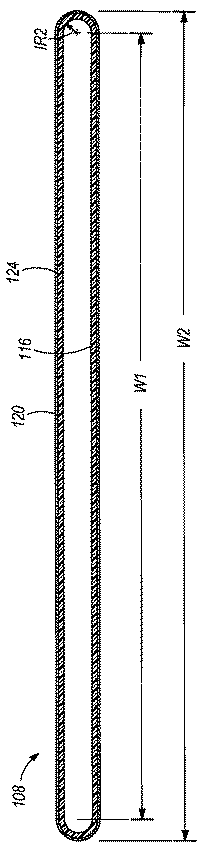
燃料レール内のダンパーの位置は、減衰のレベルに影響を及ぼし、燃料レール104に沿って多くの独立した減衰チャンバ216を配置することによりこの状態を改善する。第3に、ダンパー208を便利な長さのマスターストリップとして製造でき、次いで燃料レール104の長さにあった大きさに切断する。例えば、マスターストリップは、60個の減衰チャンバ216を持つように形成されていてもよく、次いで、各々が20個の減衰チャンバ216を持つ三つのダンパー208に切断し細分する。同じマスターストリップを、各々15個の減衰チャンバ216を持つ四つのダンパーに切断し細分してもよい。このようにして、ダンパー208を製造する製造方法は、燃料レールの長さ及び減衰チャンバ216の所望の数に関わらずほぼ同じである。
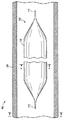
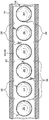
104 燃料レール
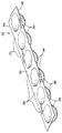
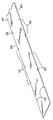
108 ダンパー
110 中央部分
112 端部
116 内部減衰チャンバ
120 メンブレン(すなわち、膜又は膜状体)
124 保護コーティング
Claims (20)
- 内燃エンジンの燃料レール内の所定量の燃料中の圧力脈動を減衰するためのダンパーであって、
厚さが約0.229mm(約0.009インチ)以下の非金属製のメンブレンであって、外面を有し、前記メンブレンの少なくとも一部が、圧縮性ガスが入った内部減衰チャンバを形成する、メンブレンと、
前記メンブレンに設けた、約0.025mm(約0.001インチ)以下の厚さのコーティングであって、前記減衰チャンバ内の前記圧縮性ガスを前記燃料レール内の前記所定量の燃料から分離する連続した防湿層を形成し、前記コーティングは、金属、金属酸化物、又はメタロイドのうちの少なくとも一つを含む、コーティングとを備えた、ダンパー。 - 請求項1に記載のダンパーにおいて、
前記メンブレンの厚さは、約0.025mm乃至0.152mm(約0.001インチ乃至約0.006インチ)である、ダンパー。 - 請求項1に記載のダンパーにおいて、
前記コーティングの厚さは、約0.0127mm(約0.0005インチ)以下である、ダンパー。 - 請求項1に記載のダンパーにおいて、
前記減衰チャンバを形成する前記メンブレンの部分は、概ね半球状の形状である、ダンパー。 - 請求項1に記載のダンパーにおいて、
前記ダンパーは二つの実質的に同じメンブレンを含み、これらのメンブレンは、互いに、少なくとも20個の分離されており且つ実質的に同じ減衰チャンバを形成し、
前記メンブレンの各々は、該メンブレンよりも曲げ率が高い構造的キャリヤ部材に連結されている、ダンパー。 - 請求項5に記載のダンパーにおいて、
同数の減衰チャンバが、前記キャリヤ部材の第1側部及びこれとは反対側の第2側部の各々から延びている、ダンパー。 - 請求項1に記載のダンパーにおいて、
前記コーティングは、前記メンブレンの外面全体を実質的に覆い、前記メンブレンと前記燃料レール内の前記所定量の燃料との間に連続した防湿層を形成する、ダンパー。 - 請求項1に記載のダンパーにおいて、
前記メンブレンは、一対の全体に平らな同一平面内にある端部と、前記ダンパーが1バール(1×10³ hPa)の圧力に露呈された場合にほぼ円形の断面を持つ中間部分とを有する、ダンパー。 - 請求項8に記載のダンパーにおいて、
前記メンブレン及び前記保護コーティングは、ダンパーが1バール(1×10³ hPa)を越える圧力に露呈された場合の形状変化に対する抵抗を無視でき、前記ダンパーの前記中間部分は、約20バール(約20×103 hPa)の圧力に露呈された場合、少なくとも30:1のアスペクト比まで平らになる、ダンパー。 - 請求項1に記載のダンパーにおいて、
前記コーティングは、酸化アルミニウム、酸化珪素、酸化タンタル、酸化ニオブ、酸化ジルコニウム、酸化ハフニウム、酸化チタニウム、酸化クロム、金、銀、ニッケル、銅、アルミニウム、窒化チタニウム、及び浸炭窒化チタニウムからなる群から選択される、ダンパー。 - 請求項1に記載のダンパーにおいて、
前記コーティングは、ナノ粒子を使用した酸化膜を含む、ダンパー。 - 内燃エンジンの燃料レール内の所定量の燃料中の圧力脈動を減衰するためのダンパーであって、
非金属製のメンブレンを備え、該メンブレンは、複数の減衰チャンバを少なくとも部分的に形成するほぼ半球形形状の複数の部分を含み、前記複数の減衰チャンバの各々には圧縮性ガスが入っており、前記メンブレンは、更に、前記複数の半球形形状部分の各々の間を延びる実質的に平らな連結部分を含み、
前記ダンパーは、また、
前記複数の減衰チャンバの各々の内部の前記圧縮性ガスを前記燃料レール内の前記所定量の燃料から分離する連続した防湿層を形成するコーティングであって、金属、金属酸化物、又はメタロイドのうちの少なくとも一つを含む前記コーティングと、
曲げ率が前記メンブレンよりも高いほぼ平らなキャリヤ部材とを備え、
前記メンブレンの前記連結部分は、前記キャリヤ部材の第1面に固定されており、前記複数の減衰チャンバの各々をシールし、前記複数の減衰チャンバを互いから分離する、ダンパー。 - 請求項12に記載のダンパーにおいて、
第1メンブレンと同様の第2メンブレンが、前記キャリヤ部材の第2面に連結されており、複数の第2減衰チャンバが前記第2面から延びるようになっている、ダンパー。 - 請求項12に記載のダンパーにおいて、
前記メンブレンの厚さは、約0.025mm(約0.001インチ)乃至約0.152mm(約0.006インチ)である、ダンパー。 - 請求項12に記載のダンパーにおいて、
前記コーティングの厚さは、約0.0127mm(約0.0005インチ)以下である、ダンパー。 - 請求項12に記載のダンパーにおいて、
前記ダンパーの存在による、前記燃料レールを通る燃料の流れに対する抵抗を低減するため、前記キャリヤ部材には複数の凹所が設けられている、ダンパー。 - 請求項12に記載のダンパーにおいて、
前記コーティングは、前記メンブレンの外面全体を実質的に覆い、前記メンブレンと前記燃料レール内の前記所定量の燃料との間に連続した防湿層を形成する、ダンパー。 - 請求項12に記載のダンパーにおいて、
前記ダンパーは、前記ダンパーの減衰チャンバの数よりも多い複数の減衰チャンバを持つマスターストリップから切断される、ダンパー。 - 請求項12に記載のダンパーにおいて、
前記コーティングは、酸化アルミニウム、酸化珪素、酸化タンタル、酸化ニオブ、酸化ジルコニウム、酸化ハフニウム、酸化チタニウム、酸化クロム、金、銀、ニッケル、銅、アルミニウム、窒化チタニウム、及び浸炭窒化チタニウムからなる群から選択される、ダンパー。 - 請求項12に記載のダンパーにおいて、
前記コーティングは、ナノ粒子を使用した酸化膜を含む、ダンパー。
Applications Claiming Priority (2)
| Application Number | Priority Date | Filing Date | Title |
|---|---|---|---|
| US12/351,255 US7694664B1 (en) | 2009-01-09 | 2009-01-09 | Fuel rail damper |
| US12/351,255 | 2009-01-09 |
Publications (2)
| Publication Number | Publication Date |
|---|---|
| JP2010159759A true JP2010159759A (ja) | 2010-07-22 |
| JP5570226B2 JP5570226B2 (ja) | 2014-08-13 |
Family
ID=41697768
Family Applications (1)
| Application Number | Title | Priority Date | Filing Date |
|---|---|---|---|
| JP2010001075A Expired - Fee Related JP5570226B2 (ja) | 2009-01-09 | 2010-01-06 | 燃料レールダンパー |
Country Status (3)
| Country | Link |
|---|---|
| US (1) | US7694664B1 (ja) |
| EP (1) | EP2206913B1 (ja) |
| JP (1) | JP5570226B2 (ja) |
Cited By (1)
| Publication number | Priority date | Publication date | Assignee | Title |
|---|---|---|---|---|
| JP2020169686A (ja) * | 2019-04-03 | 2020-10-15 | 株式会社十川ゴム | 水栓用ダンパー構造、水栓用ダンパー構造を備える水栓、及び水栓における音の低減方法 |
Families Citing this family (13)
| Publication number | Priority date | Publication date | Assignee | Title |
|---|---|---|---|---|
| EP2110542A1 (en) * | 2008-04-17 | 2009-10-21 | Continental Automotive GmbH | Fuel rail of a combustion engine |
| US8511287B2 (en) * | 2009-09-08 | 2013-08-20 | EcoMotors International | Supercritical-state fuel injection system and method |
| DE102010062855A1 (de) * | 2010-12-10 | 2012-07-19 | Continental Automotive Gmbh | Dämpfungsvorrichtung und Kraftstoffsystem für eine Brennkraftmaschine |
| FR2989122B1 (fr) | 2012-04-10 | 2016-02-05 | Coutier Moulage Gen Ind | Rampe d'injection de carburant pour moteur a combustion interne |
| US20140041635A1 (en) * | 2012-08-09 | 2014-02-13 | GM Global Technology Operations LLC | Fuel rail connector |
| US9518544B2 (en) | 2013-03-19 | 2016-12-13 | Delphi Technologies, Inc. | Fuel rail with pressure pulsation damper |
| DE102015111803A1 (de) * | 2015-07-21 | 2017-01-26 | Volkswagen Ag | Aggregat und Dämpfungsvorrichtung mit einem Dämpfungselement sowie Dämpfungselement |
| US10993716B2 (en) | 2017-06-27 | 2021-05-04 | Ethicon Llc | Surgical anvil arrangements |
| DE102018209787A1 (de) * | 2018-06-18 | 2019-12-19 | Robert Bosch Gmbh | Brennstoffverteiler für Brennkraftmaschinen |
| US10731611B2 (en) | 2018-12-21 | 2020-08-04 | Robert Bosch Llc | Fuel rail damper with locating features |
| DE102019101135A1 (de) * | 2019-01-17 | 2020-07-23 | Bayerische Motoren Werke Aktiengesellschaft | Brennkraftmaschine mit einem Kraftstoffeinspritzsystem |
| DE102019103041B4 (de) * | 2019-02-07 | 2022-12-29 | Dr. Ing. H.C. F. Porsche Aktiengesellschaft | Sammeldruckleitung für ein Kraftstoffeinspritzsystem einer Verbrennungskraftmaschine |
| US12134986B1 (en) | 2024-01-23 | 2024-11-05 | General Electric Company | Acoustic damping device |
Citations (10)
| Publication number | Priority date | Publication date | Assignee | Title |
|---|---|---|---|---|
| FR1509914A (fr) * | 1964-01-17 | 1968-01-19 | Ass Eng Ltd | Dispositif amortisseur des ondes de pression pour pipe d'alimentation de carburant de moteurs à combustion interne |
| JPH02242702A (ja) * | 1988-11-14 | 1990-09-27 | Bull Sa | 梱包方法、梱包パッド及び梱包ライン |
| JPH04242560A (ja) * | 1990-05-25 | 1992-08-31 | W R Grace & Co | 密封性ラミネート、該ラミネートから作製されたパック及び該ラミネートの製造方法 |
| JP3049185U (ja) * | 1997-11-25 | 1998-06-02 | 株式会社三共 | クッション材及びクッション体 |
| JPH11329147A (ja) * | 1998-05-12 | 1999-11-30 | Porimatec Kk | フィルム皿バネ |
| US6016841A (en) * | 1997-08-27 | 2000-01-25 | Autoliv Asp, Inc. | Accumulator with low permeability flexible diaphragm |
| JP2001510406A (ja) * | 1997-01-31 | 2001-07-31 | エル・アール・シー・プロダクツ・リミテッド | コンドーム |
| US20040107943A1 (en) * | 2002-12-10 | 2004-06-10 | Alder Randall F. | Damper for a fluid system |
| JP2005156922A (ja) * | 2003-11-26 | 2005-06-16 | Toshiba Corp | 屈折率可変素子、屈折率変化方法及び光配線基板 |
| JP2007083288A (ja) * | 2005-09-22 | 2007-04-05 | Harima Chem Inc | 導電性接合の形成方法 |
Family Cites Families (23)
| Publication number | Priority date | Publication date | Assignee | Title |
|---|---|---|---|---|
| US3075576A (en) * | 1959-07-30 | 1963-01-29 | Herbert Danuta | Improvements in reservoirs for internal combustion engines |
| ATE56513T1 (de) | 1986-06-11 | 1990-09-15 | Nussbaum & Co Ag R | Vorrichtung zum daempfen von druckstoessen in rohrleitungen, insbesondere sanitaerinstallationen. |
| JPH0290359U (ja) | 1988-12-28 | 1990-07-18 | ||
| DE4341368A1 (de) | 1993-12-04 | 1995-06-08 | Bosch Gmbh Robert | Dämpferelement zur Dämpfung von Druckschwingungen |
| US5896843A (en) | 1997-11-24 | 1999-04-27 | Siemens Automotive Corporation | Fuel rail damper |
| US6076557A (en) * | 1998-06-12 | 2000-06-20 | Senior Engineering Investments Ag | Thin wall, high pressure, volume compensator |
| US6205979B1 (en) | 1998-11-24 | 2001-03-27 | Robert Bosch Corporation | Spring locator for damping device |
| US6418909B2 (en) | 1998-11-24 | 2002-07-16 | Robert Bosch Corporation | Low cost hydraulic damper element and method for producing the same |
| DE19854551A1 (de) * | 1998-11-26 | 2000-05-31 | Bosch Gmbh Robert | Flachrohrdruckdämpfer zur Dämpfung von Flüssigkeits-Druckschwingungen in Flüssigkeitsleitungen |
| US6314942B1 (en) | 2000-04-25 | 2001-11-13 | Siemens Automotive Corporation | Fuel pressure dampening element |
| US6688335B2 (en) | 2000-07-14 | 2004-02-10 | Suzuki Sogyo Co., Ltd. | Liquid hammer prevention device |
| US6640783B2 (en) | 2001-02-15 | 2003-11-04 | Delphi Technologies, Inc. | Composite fuel rail with integral damping and a co-injected non-permeation layer |
| US6513500B2 (en) | 2001-04-02 | 2003-02-04 | Delphi Technologies, Inc. | Fuel rail damping device |
| US6601564B2 (en) | 2001-09-26 | 2003-08-05 | Senior Investments Ag | Flexible fuel rail |
| US6651627B2 (en) | 2001-12-12 | 2003-11-25 | Millennium Industries Corp. | Fuel rail pulse damper |
| US6672286B2 (en) | 2001-12-14 | 2004-01-06 | Siemens Automotive Corporation | Corrugated fuel rail damper |
| US6854447B2 (en) | 2001-12-14 | 2005-02-15 | Siemens Vdo Automotive Corp. | Corrugated internal fuel rail damper |
| JP2004251291A (ja) | 2003-02-17 | 2004-09-09 | Sankei Giken:Kk | 制振継手 |
| US7165535B2 (en) | 2004-05-27 | 2007-01-23 | Delphi Technologies, Inc. | Fuel rail pulse damper with improved end crimp |
| US6901914B1 (en) | 2004-08-27 | 2005-06-07 | Delphi Technologies, Inc. | Variable stiffness fuel rail pulse damper having extended dynamic range |
| US7341045B2 (en) | 2004-10-15 | 2008-03-11 | Robert Bosch Gmbh | Hydraulic damper element |
| US7497202B2 (en) | 2004-10-15 | 2009-03-03 | Robert Bosch Gmbh | Hydraulic damper element |
| US7146965B1 (en) | 2005-05-31 | 2006-12-12 | Automotive Components Holdings, Llc | Enhanced fuel pressure pulsation damping system with low flow restriction |
-
2009
- 2009-01-09 US US12/351,255 patent/US7694664B1/en active Active
- 2009-11-19 EP EP09014436A patent/EP2206913B1/en not_active Not-in-force
-
2010
- 2010-01-06 JP JP2010001075A patent/JP5570226B2/ja not_active Expired - Fee Related
Patent Citations (10)
| Publication number | Priority date | Publication date | Assignee | Title |
|---|---|---|---|---|
| FR1509914A (fr) * | 1964-01-17 | 1968-01-19 | Ass Eng Ltd | Dispositif amortisseur des ondes de pression pour pipe d'alimentation de carburant de moteurs à combustion interne |
| JPH02242702A (ja) * | 1988-11-14 | 1990-09-27 | Bull Sa | 梱包方法、梱包パッド及び梱包ライン |
| JPH04242560A (ja) * | 1990-05-25 | 1992-08-31 | W R Grace & Co | 密封性ラミネート、該ラミネートから作製されたパック及び該ラミネートの製造方法 |
| JP2001510406A (ja) * | 1997-01-31 | 2001-07-31 | エル・アール・シー・プロダクツ・リミテッド | コンドーム |
| US6016841A (en) * | 1997-08-27 | 2000-01-25 | Autoliv Asp, Inc. | Accumulator with low permeability flexible diaphragm |
| JP3049185U (ja) * | 1997-11-25 | 1998-06-02 | 株式会社三共 | クッション材及びクッション体 |
| JPH11329147A (ja) * | 1998-05-12 | 1999-11-30 | Porimatec Kk | フィルム皿バネ |
| US20040107943A1 (en) * | 2002-12-10 | 2004-06-10 | Alder Randall F. | Damper for a fluid system |
| JP2005156922A (ja) * | 2003-11-26 | 2005-06-16 | Toshiba Corp | 屈折率可変素子、屈折率変化方法及び光配線基板 |
| JP2007083288A (ja) * | 2005-09-22 | 2007-04-05 | Harima Chem Inc | 導電性接合の形成方法 |
Cited By (2)
| Publication number | Priority date | Publication date | Assignee | Title |
|---|---|---|---|---|
| JP2020169686A (ja) * | 2019-04-03 | 2020-10-15 | 株式会社十川ゴム | 水栓用ダンパー構造、水栓用ダンパー構造を備える水栓、及び水栓における音の低減方法 |
| JP7300299B2 (ja) | 2019-04-03 | 2023-06-29 | 株式会社十川ゴム | 水栓用ダンパー構造、水栓用ダンパー構造を備える水栓、及び水栓における音の低減方法 |
Also Published As
| Publication number | Publication date |
|---|---|
| US7694664B1 (en) | 2010-04-13 |
| JP5570226B2 (ja) | 2014-08-13 |
| EP2206913A1 (en) | 2010-07-14 |
| EP2206913B1 (en) | 2012-07-11 |
Similar Documents
| Publication | Publication Date | Title |
|---|---|---|
| JP5570226B2 (ja) | 燃料レールダンパー | |
| EP2071179A1 (en) | Hydraulic damper element | |
| CN100582546C (zh) | 流体连接装置 | |
| US6314942B1 (en) | Fuel pressure dampening element | |
| JP5786893B2 (ja) | 燃料供給システム | |
| US5301707A (en) | Anti-whistling duckbill valve | |
| JP2009156255A (ja) | 自己減衰式燃料レール | |
| JP2003533654A (ja) | 液圧減衰ブッシュ | |
| US20060066016A1 (en) | Fluid filled vibration damping device | |
| CN102996701B (zh) | 流体封入式筒形隔振装置 | |
| EP3243018B1 (en) | Pulse dampener with automatic pressure-compensation | |
| US6901914B1 (en) | Variable stiffness fuel rail pulse damper having extended dynamic range | |
| CN101802479A (zh) | 衰减装置特别是脉动衰减器 | |
| JP5427016B2 (ja) | 減衰バルブ | |
| JP2002531749A (ja) | 液体導管における液体圧力振動を減衰するための扁平管圧力減衰器 | |
| JP2006521965A (ja) | 流体駆動の作動装置における流体攪乱の減衰 | |
| WO2002006680A1 (fr) | Accumulateur | |
| US7341045B2 (en) | Hydraulic damper element | |
| US20070222129A1 (en) | Apparatus for isolating vibration | |
| EP3365546B1 (en) | Layered diaphragm | |
| JP4711238B2 (ja) | 吸気装置 | |
| JP5202224B2 (ja) | 防振装置 | |
| KR102387707B1 (ko) | 연료계통의 딜리버리파이프 맥동감쇠 기구 | |
| JPH0989038A (ja) | 流体封入式筒型マウント | |
| JP4089647B2 (ja) | 筒型防振装置 |
Legal Events
| Date | Code | Title | Description |
|---|---|---|---|
| A621 | Written request for application examination |
Free format text: JAPANESE INTERMEDIATE CODE: A621 Effective date: 20130104 |
|
| A977 | Report on retrieval |
Free format text: JAPANESE INTERMEDIATE CODE: A971007 Effective date: 20140129 |
|
| A131 | Notification of reasons for refusal |
Free format text: JAPANESE INTERMEDIATE CODE: A131 Effective date: 20140203 |
|
| A521 | Request for written amendment filed |
Free format text: JAPANESE INTERMEDIATE CODE: A523 Effective date: 20140502 |
|
| TRDD | Decision of grant or rejection written | ||
| A01 | Written decision to grant a patent or to grant a registration (utility model) |
Free format text: JAPANESE INTERMEDIATE CODE: A01 Effective date: 20140526 |
|
| A61 | First payment of annual fees (during grant procedure) |
Free format text: JAPANESE INTERMEDIATE CODE: A61 Effective date: 20140624 |
|
| R150 | Certificate of patent or registration of utility model |
Ref document number: 5570226 Country of ref document: JP Free format text: JAPANESE INTERMEDIATE CODE: R150 |
|
| R250 | Receipt of annual fees |
Free format text: JAPANESE INTERMEDIATE CODE: R250 |
|
| R250 | Receipt of annual fees |
Free format text: JAPANESE INTERMEDIATE CODE: R250 |
|
| R250 | Receipt of annual fees |
Free format text: JAPANESE INTERMEDIATE CODE: R250 |
|
| R250 | Receipt of annual fees |
Free format text: JAPANESE INTERMEDIATE CODE: R250 |
|
| R250 | Receipt of annual fees |
Free format text: JAPANESE INTERMEDIATE CODE: R250 |
|
| R250 | Receipt of annual fees |
Free format text: JAPANESE INTERMEDIATE CODE: R250 |
|
| LAPS | Cancellation because of no payment of annual fees |