JP2010146221A - Behavior recording input support system, behavior input support method, and server - Google Patents
Behavior recording input support system, behavior input support method, and server Download PDFInfo
- Publication number
- JP2010146221A JP2010146221A JP2008321724A JP2008321724A JP2010146221A JP 2010146221 A JP2010146221 A JP 2010146221A JP 2008321724 A JP2008321724 A JP 2008321724A JP 2008321724 A JP2008321724 A JP 2008321724A JP 2010146221 A JP2010146221 A JP 2010146221A
- Authority
- JP
- Japan
- Prior art keywords
- scene
- action
- data
- unit
- server
- Prior art date
- Legal status (The legal status is an assumption and is not a legal conclusion. Google has not performed a legal analysis and makes no representation as to the accuracy of the status listed.)
- Granted
Links
Images


Abstract
Description
本発明は、監視対象の生体情報や動作情報、周辺情報に関するセンサデータから監視対象の行動内容を測定する装置によって、複数種類の行動履歴を収集し、それら行動履歴から利用者の行動記録入力を支援する技術に関する。 The present invention collects a plurality of types of behavior histories by a device that measures the behavior content of the monitoring target from the sensor data related to the biological information, operation information, and peripheral information of the monitoring target, and inputs the behavior record of the user from the behavior history Related to supporting technology.
近年、人の行動内容を大量に記録・蓄積し、その大規模データを解析することにより、新たな知見を得たり、サービスを提供したりすることに期待が寄せられている。すでにインターネットの世界では検索キーワードや購買履歴を活用して、個々人に対してその人が欲しがりそうな商品のリコメンド広告を発信するなどの仕組みが確立されている。 In recent years, it has been expected to obtain new knowledge and provide services by recording and accumulating a large amount of human behavior and analyzing the large-scale data. In the Internet world, a mechanism has already been established that uses search keywords and purchase histories to send recommended advertisements for products that individuals may want.
これは実世界においても同様な仕組みが考えられる。例えば日々の業務内容を記録して解析することにより組織の業務効率の向上を図ったり、日々の生活記録を付けることにより、食事、運動、生活の規則正しさを評価し、生活習慣病予防を目的としたヘルスケアサービスを提供したり、たくさんの人の生活記録と購買履歴を分析することにより、特定の生活パターンで生活する人に対して、それらの人がよく買う商品をリコメンド広告するなどの応用が考えられる。 A similar mechanism can be considered in the real world. For example, to improve the work efficiency of the organization by recording and analyzing daily work contents, or to evaluate the regularity of meals, exercise, and life, and to prevent lifestyle-related diseases by attaching daily life records Such as providing recommended health care services, analyzing the life records and purchase histories of many people, and recommending advertisements for products that those people often buy to people living in specific lifestyle patterns Application is conceivable.
一方、現実世界の様々な情報をリアルタイムに情報処理装置に取り込むネットワークシステムが検討されている。このネットワークシステムには幅広い応用が考えられており、加速度や脈拍等の利用者の生体情報や作業状況、購買情報等の利用者の行動をモニタし、これら様々な情報を組み合わせて、利用者の状況を判定するといったような応用も提案されている。 On the other hand, a network system that takes various information in the real world into an information processing apparatus in real time has been studied. This network system is considered to have a wide range of applications, such as monitoring the user's biological information such as acceleration and pulse, work status, purchasing information, etc., and combining these various information, Applications such as determining the situation have also been proposed.
また、ある時刻におけるセンシング情報と利用者の状況を利用者の入力により紐付け、それら紐付けたデータを用いて利用者の状況を推測し、確信度の高い順に列挙する技術が知られている(例えば、特許文献1参照)。 Also, a technique is known in which sensing information at a certain time and user status are linked by user input, the user status is estimated using the linked data, and listed in descending order of confidence. (For example, refer to Patent Document 1).
また、カーナビゲーション等の経路探索時の到達確率に応じて表示態様を変える技術が知られている(例えば、特許文献2参照)。特許文献2では、過去の移動履歴に基づき到達確率を算出し、到達確率に応じて経路を色分けして表示する。
In addition, a technique for changing the display mode according to the arrival probability at the time of route search such as car navigation is known (for example, see Patent Document 2). In
また、状況の履歴及び現在の状況に応じて目的地予測を行い、予測された目的地周辺情報を予め取得しておくことによって、予測目的地周辺情報を確率の高い順に表示する、文字の大きさ、太字、色を変えるなどして画面に表示する技術が知られている(例えば、特許文献3参照)。 Also, by predicting the destination according to the history of the situation and the current situation, and obtaining the predicted destination surrounding information in advance, the predicted destination surrounding information is displayed in order of the probability. A technique for displaying on a screen by changing the bold or color is known (for example, see Patent Document 3).
この他、利用者が入力した行動開始時のコメント及び行動終了時または次の行動開始時のコメント間の行動を確信度に基づいて推測する技術(例えば、特許文献4参照)や、利用者の行動を画像化する技術が知られている(例えば、特許文献5参照)。
In addition to this, a technique (for example, refer to Patent Document 4) for inferring an action between a comment input at the start of an action entered by a user and an action between comments at the end of the action or at the start of the next action (see
日々の行動を記録、解析することに多くの有用なサービスを提供できることが期待できるが、毎日の行動内容を時刻も含めて正確に記録することは、ユーザに対してかなりの負担を強いる作業になる。そこで例えば身体に装着したセンサを用いて行動を自動的に取得する方法であれば、かなりの労力低減につながる。 It can be expected that many useful services can be provided for recording and analyzing daily behavior, but accurately recording daily behavior including time of day is a task that imposes a considerable burden on the user. Become. Therefore, for example, a method of automatically acquiring an action using a sensor attached to the body leads to a considerable labor reduction.
しかしながら、行動は単一の動作の繰り返しではなく、複数の動作が組み合わされて1つの行動が形成される。また、行動にはゆらぎがあり、同一の行動でもセンシングデータの波形が等しくなるとは限らない。例えば、監視対象が人の場合、同じ行動であっても、同じ動きを取ることは稀であり、センシングデータは等しくならない。監視対象が機器の場合、行動は稼動状態に対応するが、外的要因により動作が動的に変化するものがあり、監視対象が人の場合と同様の問題がある。ここで、ゆらぎとは、同一の行動の中には、行動する時間幅、動作の順序、動作の大きさ、等によって複数のパターンが存在することを意味する。 However, the action is not a repetition of a single action, but a plurality of actions are combined to form one action. In addition, there are fluctuations in the behavior, and the waveform of the sensing data is not necessarily equal even in the same behavior. For example, when the monitoring target is a person, even if the action is the same, it is rare to take the same movement, and the sensing data is not equal. When the monitoring target is a device, the behavior corresponds to the operating state, but there is a behavior that dynamically changes due to an external factor, and there is a problem similar to that when the monitoring target is a person. Here, fluctuation means that there are a plurality of patterns in the same action depending on the duration of action, the order of actions, the magnitude of actions, and the like.
上記従来例では、センサノードを装着した監視対象の行動について、歩行、運動、安静といった大まかな動作を自動的に識別することは可能である。しかし、監視対象が人の場合には、通勤、デスクワーク、会議、出張、家事、映画鑑賞、身支度、買い物、食事、等の利用者の行動、監視対象が機器の場合には、通常稼動、高稼働、低稼働、等の機器の行動である稼動状態、等の何をしていたかに相当する行動内容を判定することはできない。行動は複数の動作状態の組合せで構成され、それぞれの動作状態は実際に行った行動の一部でしかない。 In the above-described conventional example, it is possible to automatically identify rough actions such as walking, exercising, and resting for the behavior of the monitoring target wearing the sensor node. However, when the monitoring target is a person, commuting, desk work, meetings, business trips, housework, watching movies, dressing, shopping, eating, etc. It is not possible to determine the action content corresponding to what was being done, such as the operating state, which is the action of the device, such as operation or low operation. The action is composed of a combination of a plurality of operation states, and each operation state is only a part of the actually performed action.
また、従来例のように、既定した時間間隔単位におけるセンシングデータの基準パターンとの比較による行動の判定では、行動のゆらぎに対応できないこと、センシングデータの変化点を行動の変化点として区切る行動抽出では、同一の行動の区間が断続的に現れる場合、1つの行動が複数に区切られ、それぞれに行動が割り当てられる場合などがあること、等の理由により、行動の判定精度が低下する課題がある。 In addition, as in the conventional example, the behavior determination by comparing with the reference pattern of the sensing data in a predetermined time interval unit cannot cope with the behavior fluctuation, and the behavior extraction that separates the change point of the sensing data as the behavior change point Then, when the same action section appears intermittently, there is a problem that the action determination accuracy decreases due to the fact that one action is divided into a plurality of actions and actions are assigned to each. .
以上、上記従来例のように、単一の動作の繰り返し検出や予め既定したセンシングデータの基準パターンとの比較では、監視対象の行動を抽出することができない。そのため、これら具体的な行動については、ユーザが行動内容を逐一入力する必要があり、全ての行動についてユーザがそれぞれ内容を入力するには、多大な労力が必要となる、という問題があった。 As described above, as in the above-described conventional example, it is not possible to extract a behavior to be monitored by repeated detection of a single operation or comparison with a predetermined reference pattern of sensing data. Therefore, for these specific actions, the user needs to input action contents one by one, and there is a problem that a great deal of labor is required for the user to input the contents for all actions.
そこで本発明は、上記課題に鑑みてなされたもので、センサの測定データから判定した監視対象の行動パターン及び計算機の利用状況等の行動を表す様々な情報を組み合わせて利用して、監視対象の行動パターンを推定し、利用者の行動内容の入力を簡易にすることを目的とする。 Therefore, the present invention has been made in view of the above problems, and uses a combination of various information representing behavior such as a behavior pattern of a monitoring target determined from sensor measurement data and a usage status of a computer, and the like. The purpose is to estimate the behavior pattern and simplify the input of the user's behavior content.
本願において開示される発明のうち代表的なものの概要を簡単に説明すれば下記の通りである。 The following is a brief description of an outline of typical inventions disclosed in the present application.
すなわち、センサノードと、基地局と、サーバとからなる行動記録入力支援システムである。センサノードは、監視対象に装着されて、センサと、センサが取得したセンシングデータをサーバに送信する通信部とを有する。基地局は、ネットワークを介してサーバに接続され、受信するセンシングデータをサーバに送信する。サーバは、センシングデータを蓄積するデータ格納部と、データ格納部に蓄積されたセンシングデータから監視対象の動作状態を検出するシーン分割部と、データ格納部に格納されるシーン判定ルールに基づいて動作状態から監視対象の行動内容の候補を複数算出するシーン列挙部と、接続される表示部に複数の行動内容の候補を表示し、表示された複数の行動内容の候補から特定の行動内容が選択されると、監視対象の行動内容を確定してデータ格納部に格納する行動獲得部とを有する。 That is, it is an action record input support system including a sensor node, a base station, and a server. The sensor node is attached to a monitoring target and includes a sensor and a communication unit that transmits sensing data acquired by the sensor to a server. The base station is connected to the server via the network and transmits received sensing data to the server. The server operates based on a data storage unit that stores sensing data, a scene division unit that detects an operation state of a monitoring target from sensing data stored in the data storage unit, and a scene determination rule stored in the data storage unit A scene enumeration unit that calculates a plurality of behavior content candidates to be monitored from the state and a plurality of behavior content candidates displayed on a connected display unit, and a specific behavior content is selected from the displayed plurality of behavior content candidates Then, it has an action acquisition unit that determines the action content to be monitored and stores it in the data storage unit.
本願において開示される発明のうち代表的なものによって得られる効果を簡単に説明すれば下記の通りである。 The effects obtained by the representative ones of the inventions disclosed in the present application will be briefly described as follows.
すなわち、したがって、本発明は、監視対象の動作状態から複数の行動内容を推定し、各時間帯に行動内容の候補を提示することにより、監視対象の行動パターンに対する行動内容の入力を簡易にすることでき、行動履歴の作成に要する労力を低減できる。 That is, therefore, the present invention simplifies the input of the action content for the action pattern of the monitoring target by estimating a plurality of action contents from the operation state of the monitoring target and presenting the action content candidates in each time zone. It is possible to reduce the labor required to create an action history.
以下、本発明の実施の形態について、図面を参照しながら説明する。 Hereinafter, embodiments of the present invention will be described with reference to the drawings.
<第1の実施の形態>
本発明を適用する第1の実施例として、人に装着したセンサによって測定したセンシングデータから抽出したシーンを、人の生活行動の候補として提示することによって生活行動の記録を支援するライフログシステムを示す。
<First Embodiment>
As a first embodiment to which the present invention is applied, a life log system that supports recording of living behavior by presenting a scene extracted from sensing data measured by a sensor attached to a human as a candidate for human living behavior. Show.
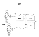
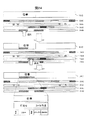
図1は、本発明を適用するライフログシステムの構成の一例を示すブロック図である。本発明のライフログシステムは、当該システムの利用者の動作(または状態)を検出するセンサとして、加速度センサを備えた腕輪型センサノード1を用い、生体情報として腕の加速度を検出する例を示す。腕輪型センサノード1は、利用者(または参加者)の腕に装着されて加速度を検出し、所定の周期で検出した加速度データ(以下、センサにより取得されたデータをセンシングデータという)を無線通信が可能な場合は基地局102のアンテナ101を介して基地局102へ送信し、有線通信が可能な場合はUSB接続などを介してクライアント計算機(PC)103へ送信する。
FIG. 1 is a block diagram showing an example of a configuration of a life log system to which the present invention is applied. The life log system of the present invention shows an example in which the bracelet
図1において、基地局102及びPC103は複数の腕輪型センサノード1と通信を行い、各腕輪型センサノード1から利用者の動きに応じたセンシングデータを受信し、ネットワーク105を介してサーバ104へ転送する。サーバ104は受信したセンシングデータを格納する。サーバ104は受信したセンシングデータを解析し、後述するように利用者の行動履歴を示すライフログを生成して格納する。
In FIG. 1, a
サーバ104が生成したライフログは、ライフログシステムの利用者が操作するクライアント計算機(PC)103で閲覧または編集することができ、利用者は、サーバ104が生成したライフログの詳細な情報を付加することができる。
The life log generated by the
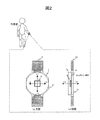
図2は、本発明のライフログシステムのセンサ部を構成する腕輪型(または腕時計型)センサノード1の一例を示す図で、図2(a)は腕輪型センサノード1の正面から見た概略図で、図2(b)は腕輪型センサノード1を側方から見た断面図である。この腕輪型センサノード1は主に利用者(装着者)の動きを測定する。
FIG. 2 is a diagram showing an example of a bracelet type (or wristwatch type)
腕輪型センサノード1は、センサや制御装置を格納するケース11と、ケース11を人体の腕に装着するバンド12を備える。
The bracelet
ケース11の内部には、図2(b)のようにマイクロコンピュータ3やセンサ6等を備えた基板10が格納される。そして、人体(生体)の動きを測定するセンサ6としては、図中X−Y−Zの3軸の加速度をそれぞれ測定する加速度センサを採用した例を示す。なお、本実施形態では、腕輪型センサノード1には図示しない温度センサを備え、利用者の体温を測定し、加速度とともにセンシングデータとして出力するものとする。
Inside the case 11 is stored a
図3は、腕輪型センサノード11の基板10に取り付けられた電子回路のブロック図を示す。図3において、基板10には、基地局102と通信を行うアンテナ5を備えた無線通信部(RF)2と、PC103と有線接続するUSB通信部39と、センサ6と及び無線通信部2を制御するマイクロコンピュータ3と、マイクロコンピュータ3を間欠的に起動するためのタイマとして機能するリアルタイムクロック(RTC)4と、各部に電力を供給する電池7と、センサ6への電力の供給を制御するスイッチ8が配置される。また、スイッチ8とセンサ6の間には、バイパスコンデンサC1が接続されてノイズの除去や、充放電の速度を低減して無駄な電力消費を防ぐ。バイパスコンデンサC1への充放電回数を減らすようにスイッチ8を制御することによって、無駄な電力消費を抑えることが可能になる。
マイクロコンピュータ3は、演算処理を実行するCPU34と、CPU34で実行するプログラムなどを格納するROM33と、データなどを格納するRAM32と、RTC4からの信号(タイマ割り込み)に基づいてCPU34に割り込みをかける割り込み制御部35と、センサ6から出力されたアナログ信号をデジタル信号に変換するA/Dコンバータ31と、無線通信部2及びUSB通信部39との間でシリアル信号にて信号の送受を行うシリアルコミュニケーションインターフェース(SCI)36と、無線通信部2及びUSB通信部39とスイッチ8を制御するパラレルインターフェース(PIO)37と、マイクロコンピュータ3内の上記各部へクロックを供給する発振部(OSC)30とを含んで構成される。そして、マイクロコンピュータ3内の上記各部はシステムバス38を介して接続される。RTC4は、マイクロコンピュータ3の割り込み制御部35に予め設定されている所定の周期で割り込み信号(タイマ割り込み)を出力し、また、SCI36へ基準クロックを出力する。PIO37はCPU34からの指令に応じてスイッチ8のON/OFFを制御し、センサ6への電力供給を制御する。
FIG. 3 shows a block diagram of an electronic circuit attached to the
The
腕輪型センサノード1は、所定の周期(例えば、1分等)でマイクロコンピュータ3を起動して、センサ6からセンシングデータを取得し、取得したセンシングデータに腕輪型センサノード1を特定する識別子とタイムスタンプを付与して基地局102またはPC103へ送信する。なお、腕輪型センサノード1の制御の詳細は、例えば、特開2008−59058号公報等と同様にすることができる。なお、腕輪型センサノード1は、連続的に取得したセンシングデータを、周期的に基地局102またはPC103へ送信するようにしても良い。
The bracelet
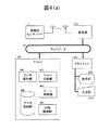
図4(a)は、図1に示した本発明を適用するライフログシステムの機能要素を示すブロック図である。腕輪型センサノード1が送信したセンシングデータは、基地局102を介してサーバ104のデータ格納部500に蓄積される。
FIG. 4A is a block diagram showing functional elements of a life log system to which the present invention shown in FIG. 1 is applied. Sensing data transmitted from the bracelet
クライアント103は、各種情報を表示する表示部1031と利用者の操作によって様々な情報の入力を可能とする入力部1032を具備する。
The
サーバ104は、図示しないプロセッサとメモリ及びストレージ装置を備えて、利用者の腕の加速度で測定されたセンシングデータを集計し、データ集計部200、シーン分割部300、シーン列挙部400、及び行動獲得部500を実行する。データ集計部200は、単位時間(例えば、1分間)毎の集計値を算出し、データ格納部600に格納する。シーン分割部300は、センシングデータおよび前記集計した集計データを解析して、個別の動作状態であるシーン領域および個々の運動状態であるシーン断片を抽出し、データ格納部600に格納する。シーン列挙部400は、抽出したシーン領域とシーン断片に対して、過去データから作成したルール、または、予め登録したシーン判定ルールを適用することによって、行動内容の候補であるシーンを抽出し、データ格納部600に格納する。行動獲得部500は、抽出したシーンを利用者のクライアント計算機103に提示し、利用者が選択したシーンを利用者が入力した行動内容と共にデータ格納部600に格納する。
The
なお、データ格納部600に格納されるセンシングデータには腕輪型センサノード1の識別子が付与され、また、行動内容、動作状態、シーン、および、行動記録のデータには利用者を特定する識別子(例えば、腕輪型センサノード1の識別子)が付与されて、利用者を識別することができる。
The identifier of the bracelet
ここで動作状態は、センシングデータに基づき判定した睡眠、歩行、安静などの利用者の動作の様子を表し、行動内容は、散歩、映画鑑賞などの利用者の実際の行動の内容を表す。 Here, the operation state represents the state of the user's operation such as sleep, walking, rest, etc. determined based on the sensing data, and the action content represents the content of the actual action of the user, such as a walk or watching a movie.
シーン分割部300とシーン列挙部400と行動獲得部500は、例えば、プログラムとしてストレージ装置(記憶媒体)に格納され、所定のタイミングでメモリへロードされてプロセッサにより実行される。なお、以下では、サーバ104が、シーン分割部300とシーン列挙部400を所定の周期(例えば、5分間)毎に実行する例、および、行動獲得部500を利用者から要求されたタイミングで実行する例を示す。
The
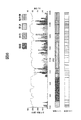
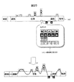
図5は、本発明を適用するライフログシステムで行われるデータ処理の全体的な流れを示す図である。まず、ステップS1では、腕輪型センサノード1が送信したセンシングデータを基地局102またはPC103がサーバ104へ転送し、サーバ104のデータ格納部600にセンシングデータを蓄積する。さらに、サーバ104が所定の周期になるとデータ集計部200を実行して、データ格納部600に蓄積されたセンシングデータから単位時間毎の運動頻度を算出し、データ格納部600に格納する。この運動頻度の算出結果は図6(動作頻度)で示すように単位時間毎の運動頻度を時系列的にソートしたデータとなる。運動頻度の算出方法は、図7、図8を用いて後述する。
FIG. 5 is a diagram showing an overall flow of data processing performed in the life log system to which the present invention is applied. First, in step S <b> 1, the sensing data transmitted from the bracelet
次に、ステップS2では、サーバ104が所定の周期になるとシーン分割部300を実行して、データ格納部600に蓄積されたセンシングデータと集計データから利用者の一連の動作状態であるシーン領域、および、シーン領域を構成する運動であるシーン断片を作成する。
Next, in step S2, when the
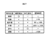
このシーン領域の作成処理は、センシングデータまたは集計データから抽出可能である所定の動作状態(例えば、歩行、睡眠)を検出し、検出された動作状態、および、検出された動作状態と次の動作状態に挟まれた期間をシーン領域として抽出し、後述する所定の判定ルールを用いて睡眠、安静、軽作業、作業、歩行、運動の動作内容を判定し、各シーン領域に割り当てるものである。 This scene area creation process detects a predetermined operation state (for example, walking, sleep) that can be extracted from sensing data or aggregated data, and detects the detected operation state, and the detected operation state and the next operation. The period between the states is extracted as a scene area, and the operation contents of sleep, rest, light work, work, walking, and exercise are determined using a predetermined determination rule described later, and assigned to each scene area.
さらに、シーン断片の作成処理は、前記抽出されたシーン領域毎に、センシングデータまたは所定時間内のセンシングデータの集計データから時系列的なデータの変化点を検出し、変化点から次の変化点までを1つの運動単位であるシーン断片として抽出し、シーン断片の抽出方法ごとに断片分類を割り当てる。そして、断片分類ごとに、運動量の統計値を用いたグループ分け、センシングデータの類似度を用いたグループ分け、集計データの類似度を用いたグループ分けなど1以上グループ分けにより、グループの識別子である断片分類の値を割り当てる。センシングデータまたは集計データの変化点とは、激しく動いている状態から静かになった時点などを変化点として抽出する。上記の処理により、シーン分割部300は所定の周期毎にシーン領域とシーン断片を作成し、データ格納部600に格納する。図6に、睡眠、歩行、安静、軽作業の動作状態をシーン領域として抽出した例、シーン領域ごとにシーン断片を抽出した例、シーン領域とシーン断片の関係の例を図示する。
Further, the scene fragment creation process detects, for each of the extracted scene areas, a time-series data change point from the sensing data or the total data of sensing data within a predetermined time, and from the change point to the next change point. Is extracted as a scene fragment, which is one motion unit, and a fragment classification is assigned for each method of scene fragment extraction. And, for each fragment classification, it is a group identifier by one or more grouping such as grouping using the statistics of momentum, grouping using the similarity of sensing data, grouping using the similarity of aggregated data, etc. Assign fragment classification values. The change point of the sensing data or the total data is extracted as a change point when it becomes quiet from the state of intense movement. Through the above processing, the
次に、サーバ104は、ステップS3でシーン分割部300が抽出したシーン領域、シーン断片、及び前後の行動内容が既に確定している場合にはその行動内容を、登録されているシーン判定ルールに従って判定し、利用者の行動内容の候補であるシーンを作成し、データ格納部600に格納する。
Next, when the scene area, the scene fragment, and the preceding and following action contents extracted by the
登録されたシーン判定ルールは、利用者毎の過去の行動内容、シーン領域、シーン断片のデータから抽出したルール、または、利用者を含むデータ格納部600に格納された行動内容、シーン領域、シーン断片のデータから作成したルール、または、既知の知識を用いて構築したルールである。具体的には、行動内容、シーン領域、シーン断片、時間情報の組合せと順序パターンから作成され、行動内容の候補であるシーンを判定するためのものである。シーン判定ルールの構造及びシーン判定の例は、図21において後述する。
The registered scene determination rule is a rule extracted from past action content, scene area, and scene fragment data for each user, or action content, scene area, scene stored in the
例えば、早朝の歩行という動作内容であれば、具体的な行動内容の候補は散歩とすることができ、あるいは、「起床後30〜90分の間で歩行(10−15分)、安静(20−25分)、歩行(7−10分)であれば、その利用者の通常の生活においては定型化している「通勤」として判定する。なお、行動内容は動作内容の組合せなので、多くの場合複数のシーン領域から成り立つが、上述の散歩のように、単一の動作内容と時刻から定まる行動内容も存在する。 For example, if the action content is early morning walking, the specific action content candidate can be a walk, or “walking (10-15 minutes) and resting (20-15 minutes after waking up) (20 -25 minutes) and walking (7-10 minutes), it is determined as “commuting” which is standardized in the normal life of the user. Since the action content is a combination of action contents, the action contents are often composed of a plurality of scene areas, but there are action contents determined from a single action content and time as in the above-described walk.
次に、行動獲得部500は、データ格納部に格納されたシーンから、利用者が行った行動内容に一致する可能性の高い順に提示する優先順位を付与する(ステップS4)。
Next, the
次に、サーバ104は、ステップS5で、上記優先順位に従って、各シーンをクライアント計算機103に提示する。ステップS6では、クライアント計算機103を操作する利用者が、サーバ104が抽出したシーンに対応する行動内容を確認し、優先順位の順で提示されたシーンを選択することで、利用者は容易に日々の生活記録(ライフログ)の生成することができる。
Next, in step S5, the
次に、ステップS7では、クライアント計算機103で選択されたシーンを行動記録として確定する。
Next, in step S7, the scene selected by the
こうして作成されたライフログは、ステップS8で利用者の識別子と作成日時などのタイムスタンプとともに、サーバ104のデータ格納部600へ格納される。
The life log created in this way is stored in the
図7は、サーバ104のデータ集計部200で行われる処理の一例を示すフローチャートである。まず、データ集計部200は、利用者の識別子に対応するセンシングデータをデータ格納部600から読み込む(ステップS11)。ここで、データ集計部200が読み込むセンシングデータの量は、センシングデータの集計周期である所定の周期(例えば、3分間)等に設定すればよい。
FIG. 7 is a flowchart illustrating an example of processing performed by the
次に、ステップS12では、データ集計部200が読み込んだセンシングデータの加速度データについて所定の時間間隔(例えば、1分)毎の集計値を算出する。本実施形態では、所定の時間間隔内での腕輪型センサノード1の装着者(利用者)の運動の頻度を示すゼロクロス回数を集計値として用いる。
Next, in step S12, the total value for every predetermined time interval (for example, 1 minute) is calculated about the acceleration data of the sensing data read by the
腕輪型センサノード1が検出したセンシングデータにはX、Y、Z軸の加速度データが含まれているので、データ集計部200は、X、Y、Zの3軸の加速度のスカラー量を算出し、スカラー量が0または0近傍の所定値を通過する値をゼロクロス回数として算出し、ゼロクロス回数が所定時間間隔内に出現する頻度を算出し、この出現頻度を、所定の時間間隔(1分間)の運動頻度として出力する。
Since the sensing data detected by the bracelet
まず、スカラー量は、各軸の加速度をXg、Yg、Zgとすると、スカラー量=(Xg2+Yg2+Zg2)1/2で求められる。 First, the scalar quantity is obtained by scalar quantity = (Xg2 + Yg2 + Zg2) 1/2 where Xg, Yg, and Zg are accelerations of respective axes.
次に、求めたスカラー量をフィルタ(バンドパスフィルタ)処理し、所定の周波数帯域(例えば、0.1Hz〜5Hz)のみを抽出し、ノイズ成分を除去する。そして、図8で示すように、フィルタ処理を施した加速度のスカラー量が所定の閾値(例えば、0.05G)となった回数をゼロクロス回数として算出する。あるいは、加速度のスカラー量が所定の閾値をよぎった回数をゼロクロス回数とする。そして、所定の時間間隔内のゼロクロス回数を運動頻度として求める。また、所定の時間間隔内の運動量の積分値をゼロクロス回数とスカラー量から求めて、この積分値を運動強度とする。またセンシングデータに含まれる温度についても所定の時間間隔内の平均温度を求める。なお、運動頻度は、XYZの各方向の加速度の値が、正と負に振動した回数(振動数)を各方向の所定時間内で数えて合計してもよいが、本実施形態では、計算を簡略化することができるため、ゼロクロス回数を算出する方法について説明した。 Next, the obtained scalar quantity is subjected to filter (bandpass filter) processing, and only a predetermined frequency band (for example, 0.1 Hz to 5 Hz) is extracted to remove a noise component. Then, as shown in FIG. 8, the number of times that the scalar amount of the acceleration subjected to the filter processing becomes a predetermined threshold (for example, 0.05 G) is calculated as the number of zero crossings. Alternatively, the number of times that the scalar amount of acceleration crosses a predetermined threshold is defined as the number of zero crossings. Then, the number of zero crossings within a predetermined time interval is obtained as the exercise frequency. Also, an integral value of the momentum within a predetermined time interval is obtained from the number of zero crossings and a scalar amount, and this integral value is used as the exercise intensity. Also, an average temperature within a predetermined time interval is obtained for the temperature included in the sensing data. The motion frequency may be summed by counting the number of times that the acceleration value in each direction of XYZ vibrates positively and negatively (frequency) within a predetermined time in each direction. The method for calculating the number of zero crossings has been described.
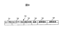
データ集計部200は、所定の時間間隔毎に、運動頻度、平均温度、運動強度を求め、図9に示すように、それらを所定の時間間隔毎の集計データとして生成し、データ格納部600へ蓄積する。図9は、所定時間間隔毎の集計データのフォーマット700を示す説明図で、センシングデータに含まれる腕輪型センサノード1の識別子を格納するセンサデータID702と、腕輪型センサノード1の装着者(ライフログシステムの利用者)の識別子を格納するユーザID701と、所定の時間間隔の開始時刻(測定日時)を格納する測定日時703と、センシングデータに含まれる温度を格納する温度704と、データ集計部200が演算した運動頻度を格納する運動頻度705と、データ集計部200が求めた運動強度を格納する運動強度706からひとつのエントリを構成する。なお、利用者の識別子は、腕輪型センサノード1の識別子に基づいて予め設定した図示しないテーブルから参照すればよい。
The
図10は、サーバ104のシーン分割部300で行われるシーン領域とシーン断片の作成処理を示すフローチャートである。まず、シーン分割部300は、利用者の識別子に対応するセンシングデータと集計データをデータ格納部600から読み込む(ステップS21)。ここで、シーン分割部300が読み込む集計データの量は、シーン領域作成の周期である所定の周期(例えば、5分間)などに設定すればよい。
FIG. 10 is a flowchart showing a scene area and scene fragment creation process performed by the
次に、ステップS22では、シーン分割部300が読み込んだセンシングデータと集計データから所定の動作状態を検出し、シーン領域を作成する。ここで、所定の動作状態は、センシングデータまたは集計データから検出可能な動作状態であり、例えば歩行、睡眠である。
Next, in step S22, a predetermined operation state is detected from the sensing data and total data read by the
例えば歩行状態を検知する手法は、上下方向の加速度が周期的に変化する(一歩ごとの着地)、前後方向の加速度が上下方向の加速度と同期して規則的に前方向と後ろ方向を繰り返す(着地するごとの速度変化)、左右方向の加速度が上下方向の加速度に同期して規則的に繰り返す(一歩ごとの体の左右へのゆれ)、といった波形が観測でき、さらに腕の振りが重なった波形として観測できるので、これらにより、該当するシーンが歩行状態であるか否かを判定できる。また、ゼロクロスの周期の逆数を歩数として検知することも可能である。これらの人体に装着した加速度センサから歩行状態を検知する手法は、公知の手法を用いれば良い。 For example, in the method of detecting the walking state, the acceleration in the vertical direction changes periodically (landing for each step), and the acceleration in the front-rear direction repeats the front and rear directions regularly in synchronization with the acceleration in the vertical direction ( (Changes in speed at each landing), and the left and right accelerations repeat regularly (swing to the left and right of the body step by step) in synchronization with the vertical acceleration, and the arm swings further. Since it can be observed as a waveform, it can be determined whether or not the corresponding scene is in a walking state. It is also possible to detect the reciprocal of the zero-cross cycle as the number of steps. A known method may be used as a method for detecting the walking state from the acceleration sensor attached to the human body.
また、睡眠は、運動頻度は極めて低いが、睡眠中でも人体は寝返りなどの運動を行うため、運動頻度はゼロにはならない。睡眠を判定する手法についても公知の手法を用いればよい。 In addition, although the exercise frequency of sleep is extremely low, since the human body exercises such as turning over during sleep, the exercise frequency does not become zero. A known method may be used as a method for determining sleep.
次に、歩行、睡眠に該当しないシーン領域に対して、図27に示す判定値のテーブルを参照し、各シーン領域の運動頻度が「安静」、「軽作業」、「作業」、「運動」の各判定値と比較して何れに該当するかを判定する。 Next, with reference to the determination value table shown in FIG. 27 for scene areas not corresponding to walking or sleeping, the motion frequency of each scene area is “rest”, “light work”, “work”, “exercise”. Compared with each determination value, it is determined which corresponds.
次に、ステップS23では、前記抽出された各シーン領域について、当該シーン領域の開始日時と終了日時の期間に該当する集計データから、時系列的な運動頻度の変化点を検出し、変化点間を同一の運動を行った単位であるシーン断片として抽出してデータ格納部600に格納する。
Next, in step S23, for each of the extracted scene areas, a time-series change point of the exercise frequency is detected from the total data corresponding to the start date and time and end date and time of the scene area, Are extracted as scene fragments, which are units of the same exercise, and stored in the
以上の処理により、シーン分割部300はセンシングデータと集計データから動作状態の単位であるシーン領域と運動変化の単位であるシーン断片を抽出する。
Through the above processing, the
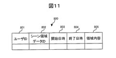
図11は、データ格納部600に格納されるシーン領域データ800のフォーマットを示す説明図で、利用者の識別子を格納するユーザID801と、シーン領域データの識別子であるシーン領域データID802と、シーン領域の開始日時803と、終了日時804と、シーン領域の動作状態を示す領域内容805とからひとつのエントリを構成する。
FIG. 11 is an explanatory diagram showing the format of the
図12は、データ格納部600に格納されるシーン断片データのフォーマット900を示す説明図で、利用者の識別子であるユーザID901と、対応するシーン領域データの識別子であるシーン領域データID902と、シーン断片データの開始日時903と、終了日時904と、付与されたグループの識別子である断片分類1(905)から断片分類n(906)とからひとつのエントリを構成する。
FIG. 12 is an explanatory diagram showing a
このようにユーザIDに対応づけてシーン領域データID、領域内容、断片分類等を記録しておくことにより、ユーザごとに行動内容の候補であるシーンを作成することが可能となる。 By recording the scene area data ID, area contents, fragment classification, etc. in association with the user IDs in this way, it is possible to create a scene that is a candidate for action contents for each user.
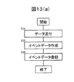
図13(a)は、イベントデータを登録する手順を示すフローチャートである。ここでイベントとは、ユーザがPC、携帯電話などを用いて行った行為であり、短時間の出来事を意味する。例えば、メール送受信、写真撮影、買い物などである。ここではメール送受信を例に手順を説明する。 FIG. 13A is a flowchart showing a procedure for registering event data. Here, the event is an action performed by the user using a PC, a mobile phone or the like, and means a short-time event. For example, email transmission / reception, photography, shopping, and the like. Here, the procedure will be described using mail transmission / reception as an example.
まず、利用者がPC103でメールを送受信した際に、ステップS24でPC103からメール送受信したことを示すデータとその時刻、及びユーザIDをサーバ104に送付する。次にステップS25で、図13(b)に示すデータを作成し、ステップS26でサーバのデータ格納部600に登録する。ここで、イベントデータの送信元はPC103に限らず、例えば利用者の携帯電話などの計算機能を持った外部機器が考えられる。このように、本実施形態のライフログシステムでは、利用者がPC又は携帯電話の操作をしてメール送受信等の行為を行った場合に、その行為がイベントデータとして、サーバに送信されるように構成される。そして、イベントデータに付与されるユーザID、行為を行った時刻とともに、サーバのデータ格納部に記録される。なお、PCあるいは携帯電話等がイベントデータをサーバに送信するタイミングは、その行為が行われたとき、所定の時間間隔、又は、利用者が指定したタイミング、など特に限定されない。
First, when the user transmits / receives mail by the
図13(b)は、データ格納部600に格納されるイベントデータのフォーマット1100を示す説明図で、利用者の識別子を格納するユーザID1101と、イベントデータの識別子であるイベントデータID1102と、イベントデータの種類をあらわすイベント分類ID1103と、イベントデータの日時1104と、イベントデータの示す内容又は利用者が付与するコメント等のイベントの内容を格納するイベント内容1105と、当該イベントと関連するシーン領域IDを格納する関連シーン1106とからひとつのエントリを構成する。イベントデータとシーン領域データとは、イベントデータの日時とシーン領域データの開始日時と終了日時により関連づけられる。また、利用者は後述する図16(c)に示すように、イベントデータにコメントを付すことができ、その内容がイベント内容として登録される。
FIG. 13B is an explanatory diagram showing a format 1100 of event data stored in the
図14は、図4(a)のライフログシステムの機能要素を示すブロック図の表示部1031に表示される、利用者の行動記録を入力するための入力支援画面の一例である。
FIG. 14 is an example of an input support screen for inputting a user's action record displayed on the
図14の入力支援画面例では、日付選択部1040、グラフ表示部1041、行動記録表示部1042、シーン領域表示部1043、イベント表示部1044を含む。
14 includes a date selection unit 1040, a graph display unit 1041, an action
日付選択部1040は、利用者が行動記録を入力する日付候補を表示し、利用者の選択により他の表示部にデータを表示するためのトリガ機能を有する。 The date selection unit 1040 has a trigger function for displaying date candidates for the user to input action records and displaying data on other display units according to the user's selection.
グラフ表示部1041は、日付選択部1040により選択された日付の腕輪型センサノード等を用いて収集した加速度に基づき算出した単位時間毎の運動頻度を時系列的にソートしたデータを表示する機能を有する。 The graph display unit 1041 has a function of displaying data in which the exercise frequency per unit time calculated based on the acceleration collected using the bracelet type sensor node of the date selected by the date selection unit 1040 is sorted in time series. Have.
行動記録表示部1042は、日付選択部1040により選択された日付の行動記録を表示、編集するための機能を有する。
The action
シーン領域表示部1043は、日付選択部1040により選択された日付の腕輪型センサノード等を用いて収集した加速度に基づき算出したシーン領域データを表示するための機能を有する。
The scene
イベント表示部1044は、日付選択部1040により選択された日付のイベントを表示するための機能を有する。
The
以下、行動記録表示部1042に行動内容を表示する第1及び第2の方法について説明する。第1の方法では、シーン領域データまたはイベントデータが表示されると、利用者が当該シーン領域データ又はイベントデータについてコメントを入力し行動内容が確定されることにより、行動記録入力の負担軽減を実現することを特徴とする。
Hereinafter, the first and second methods for displaying the action content on the action
また、第2の方法では、シーン領域データまたはイベントデータから行動記録の候補を算出し、提示することにより、行動記録入力の負担軽減を実現することを特徴とする。 Further, the second method is characterized in that the burden of action record input is reduced by calculating and presenting action record candidates from scene area data or event data.
まず、第1の方法について、図15及び図16を用いて説明する。図15はデータ表示処理の手順を示すフローチャートである。 First, the first method will be described with reference to FIGS. 15 and 16. FIG. 15 is a flowchart showing the procedure of the data display process.
まず、日付選択部1040を用いて行動記録を入力する日付を選択し、利用者の該当する日付のシーン領域データ、イベントデータ、及び既に登録されている行動記録データがある場合には行動記録データ、をデータ格納部600から抽出する(S201、S202)。抽出したシーン領域データ、イベントデータ及び行動記録データを該当部分に表示する(S203)。 First, a date for inputting an action record is selected using the date selection unit 1040, and if there is scene area data, event data, and already registered action record data of the user's corresponding date, action record data Are extracted from the data storage unit 600 (S201, S202). The extracted scene area data, event data, and action record data are displayed in the corresponding part (S203).
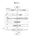
図16(a)は行動記録入力支援処理の手順を示すフローチャートである。
まず、シーン領域データ、イベントデータを行動記録入力支援画面の対応部分に表示し(S201〜S203) 、利用者がシーン領域データ、イベントデータ中から選択する(S301)と、選択されたシーン領域データ、イベントデータが行動記録表示部1042に表示される(S302)。次に、行動記録表示部に表示された当該シーン領域データ、イベントデータにコメントをつける、シーンの開始・終了時刻を調整する、イベントの位置を調整するなどの行動記録編集支援処理を行い、行動記録の入力を完了する(S303、S304)。全ての入力が完了していない場合にはS301〜S304を繰り返す(S305)。
FIG. 16A is a flowchart showing the procedure of the action record input support process.
First, scene area data and event data are displayed on the corresponding part of the action record input support screen (S201 to S203), and when the user selects from the scene area data and event data (S301), the selected scene area data is displayed. Event data is displayed on the action record display unit 1042 (S302). Next, perform action record editing support processing such as adding comments to the scene area data and event data displayed on the action record display section, adjusting the start / end time of the scene, adjusting the position of the event, etc. The recording input is completed (S303, S304). If all inputs have not been completed, S301 to S304 are repeated (S305).
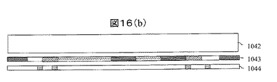
図16(b)、図16(c)に上記行動記録入力支援処理手順の画面表示の一例を示す。図16(b)はS201〜S203でシーン領域データ、イベントデータを行動記録入力支援画面の対応部分に表示した画面表示の一例である。図14に示すように、シーン領域領域表示部には、睡眠、安静、軽作業、歩行が表示され、イベント表示部には、あるイベントが表示されている。図16(c)はS301〜S303の画面表示の一例である。シーン領域表示部1043またはイベント表示部1044からシーン領域データまたはイベントデータを選択することにより、当該データを行動記録表示部1042中の、例えばシーン領域データは下段、イベントデータは上段に表示する。
FIGS. 16B and 16C show an example of a screen display of the action record input support processing procedure. FIG. 16B is an example of a screen display in which scene area data and event data are displayed on corresponding portions of the action record input support screen in S201 to S203. As shown in FIG. 14, sleep, rest, light work, and walking are displayed on the scene area display unit, and an event is displayed on the event display unit. FIG. 16C is an example of the screen display of S301 to S303. By selecting scene area data or event data from the scene
その後、利用者が、行動記録表示部1042に表示されたシーン領域データあるいはイベントデータを入力部1032を介して選択し、コメント(行動内容)を入力することにより、図14に示す睡眠、通勤、仕事などの行動内容が行動記録表示部に表示される。
After that, the user selects the scene area data or event data displayed on the action
以上説明したように、第1の方法によれば、行動記録入力の際に腕輪型センサノード1で測定できるセンサデータを用いて生成したシーン領域データ及び利用者の手入力または腕輪型センサノード1以外の機器を用いて生成・収集したイベントデータを選択することにより行動記録入力を行うことにより、利用者の行動記録入力に要する負担を軽減することが可能となる。
As described above, according to the first method, scene area data generated by using sensor data that can be measured by the bracelet
行動記録編集支援処理のシーン(行動内容)の開始・終了時刻、イベントの時刻を調整する方法については図17で説明する。 A method of adjusting the start / end time of the scene (action content) and the event time of the action record editing support process will be described with reference to FIG.
利用者が手作業でシーンの開始・終了時刻、イベントの時刻を調整する場合には、シーン断片の開始・終了時刻を目盛りとして編集する場合と、シーン領域の開始・終了時刻を目盛りとして編集する場合とがある。シーン断片に基づく目盛りはシーン断片目盛り1047に表示し、シーン領域に基づく目盛りはシーン領域目盛り1048に表示する。これらの目盛りは入力部を介して、行動記録表示部1042を利用者が指定することにより、行動獲得部により表示される。または、シーン領域表示とともに自動的に表示されるようにすることができる。このようなシーン断片目盛りあるいはシーン領域目盛りを設けることにより、利用者が手作業で行動記録の開始・終了時刻、イベントの時刻を調整する際の時刻合わせの負担を軽減することが可能となる。
When the user manually adjusts the scene start / end time and event time, the scene fragment start / end time is edited as a scale, and the scene area start / end time is edited as a scale. There are cases. A scale based on the scene fragment is displayed on the scene fragment scale 1047, and a scale based on the scene area is displayed on the scene area scale 1048. These scales are displayed by the action acquisition unit by the user specifying the action
次に、行動記録表示部1042に行動内容を表示する第2の方法について、図19乃至図21を用いて説明する。
Next, a second method for displaying the action content on the action
図19(a)は行動記録入力支援方法の手順を示すフローチャートである。 FIG. 19A is a flowchart showing the procedure of the action record input support method.
まず、利用者が日付選択部1040に行動記録を入力する日付を入力すると、シーン列挙部は、データ格納部600から該当する日付のシーン領域データ、イベントデータを抽出する(S401、S402)。次に、抽出したシーン領域とシーン断片、及び前後の行動内容が既に確定している場合にはその行動内容を、登録されているシーン判定ルールに従って判定し、シーン作成処理を行う(S403)。 First, when a user inputs a date for inputting an action record to the date selection unit 1040, the scene listing unit extracts scene area data and event data of the corresponding date from the data storage unit 600 (S401, S402). Next, when the extracted scene area and scene fragment and the action content before and after are already determined, the action content is determined according to the registered scene determination rule, and a scene creation process is performed (S403).
次に、行動獲得部は、作成したシーンのうち、確信度が予め設定されているしきい値より大きいシーン領域データを行動記録表示部1042に自動的に表示する(S404)。さらにシーン領域データ、イベントデータを行動記録入力支援画面の対応部分に表示する(S405)。利用者が行動記録表示部1042中の入力したい部分(時刻)を選択すると、選択部分を含むシーン領域データ、イベントデータの候補が表示される(S406、407)。本実施形態では、利用者はシーン領域データ、イベントデータを候補中から選択する(S408)と、選択されたシーン領域データ、イベントが行動記録表示部1042に表示される(S409)。
Next, the action acquisition unit automatically displays scene area data having a certainty factor larger than a preset threshold value on the action
次に、行動記録表示部に表示された当該シーン領域データ、イベントデータにコメントをつける、シーンの開始・終了時刻を調整する、イベントの位置を調整するなどの行動記録編集作業を行い、行動記録の入力を完了する(S410、S411)。全ての入力が完了していない場合にはS405〜S410を繰り返す(S412)。シーン領域データ、イベントデータにコメントをつける、シーンの開始・終了時刻を調整する、イベントの位置を調整するなどの処理は、第1の方法で説明した内容と同様である。 Next, perform action record editing work such as adding comments to the scene area data and event data displayed in the action record display section, adjusting the start and end times of the scene, and adjusting the event position. Is completed (S410, S411). If all inputs are not completed, S405 to S410 are repeated (S412). Processing such as adding a comment to scene area data and event data, adjusting the start / end time of the scene, adjusting the position of the event, and the like is the same as that described in the first method.
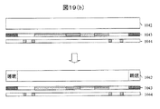
図19(b)は、S404に関する図示例である。図19(b)の例ではシーンデータ「睡眠」が確信度がしきい値以上のシーンデータであるとして自動入力されている。 FIG. 19B is an illustrative example relating to S404. In the example of FIG. 19B, the scene data “sleep” is automatically input as scene data having a certainty factor equal to or greater than a threshold value.
図19(c)は、S405〜S408に関する図示例である。利用者が入力したい部分(時刻)を選択すると選択時刻を含む開始・終了時刻、種類の異なる複数候補を含む行動記録候補表示部1060が表示される(図19(c)の上図)。このとき、表示される候補は、シーンデータの確信度が高い順または、利用者が過去に選択した頻度の高い順に表示される。利用者が候補からシーンデータを選択すると、行動記録表示部1042に行動記録が表示される(図19(c)の下図)。 FIG. 19C is an example of illustration regarding S405 to S408. When the user selects a part (time) that the user wants to input, a start / end time including the selected time and an action record candidate display unit 1060 including a plurality of different types of candidates are displayed (upper diagram in FIG. 19C). At this time, the displayed candidates are displayed in descending order of the certainty of the scene data or in descending order of frequency selected by the user in the past. When the user selects scene data from candidates, an action record is displayed on the action record display unit 1042 (the lower diagram in FIG. 19C).
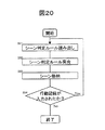
図20は、シーン列挙部400で行われるシーン作成処理(図19(a)のS403)を表すフローチャートである。シーン列挙部ではシーン判定ルールに一致するシーン領域、シーン断片、行動記録のパターンを検索し、シーン(行動内容)を抽出する。
FIG. 20 is a flowchart showing a scene creation process (S403 in FIG. 19A) performed by the
まず、ステップS51では、利用者に該当する予め登録されたシーン判定ルールをデータ格納部600から読み出す。シーン判定ルールは、条件と結論からなり、条件を満たすとある結論(シーン)が推定されるものであり、ユーザごとに予め記録されている。条件は、複数または単一のシーン領域、行動記録の組合せ、順序パターンから構成される。シーン領域は、シーン領域内容だけでなく、当該シーン領域の期間にあるシーン断片の組合せも条件となる。また、シーン領域、シーン断片、行動記録は開始日時から終了日時までの経過時間も条件となる。一方、結論は、シーン内容、シーン領域あるいは行動記録の開始日時、終了日時からなり、それらの判定精度を示す値を評価値として確信度を伴う。確信度は過去のデータから算出することが可能である、また、シーン判定ルールを専門家の知見によって作成する場合には任意に定めてもよい。
First, in step S51, a pre-registered scene determination rule corresponding to the user is read from the
図21はシーン判定ルールの構造の一例である。シーン判定ルールは条件テーブル1000と結論テーブル1100からなり、ルールIDで紐付けられている。条件テーブルは、ユーザID、ルールID、順序、種別、項目名、値、比較演算の組からなる。種別は対象となるデータの種類であるシーン領域、シーン断片、行動記録、時間情報である経過時間、時間帯、時間からなる。比較演算は、判定対象となるシーン領域データ等と一致するか否かを判定する演算式である。結論テーブルは、ユーザID、ルールID、シーン内容、開始日時、終了日時、確信度の組からなる。開始日時と終了日時は特定の値を定義せず、条件テーブルの順序に示すデータの開始日時または終了日時を指定することによって、条件テーブルの条件を満たすデータから、開始日時と終了日時を決めることができる。 FIG. 21 shows an example of the structure of the scene determination rule. The scene determination rule includes a condition table 1000 and a conclusion table 1100, and is associated with a rule ID. The condition table includes a set of user ID, rule ID, order, type, item name, value, and comparison operation. The type includes a scene area, a scene fragment, an action record, and an elapsed time, a time zone, and a time as time data. The comparison calculation is an arithmetic expression for determining whether or not the scene area data to be determined matches. The conclusion table includes a set of user ID, rule ID, scene content, start date / time, end date / time, and certainty factor. No specific value is defined for the start date / time and end date / time, and the start date / time and end date / time are determined from the data that satisfies the conditions in the condition table by specifying the start date / time or end date / time of the data shown in the order of the condition table. Can do.
例えば、ユーザID101のルールID1のシーン判定ルールは、「最初が行動記録「睡眠」であり、その後の70分以内の朝時間帯に「歩行」のシーン領域があり、次に「安静」のシーン領域、最後に「歩行」のシーン領域である場合、シーンは「通勤」であり、その確信度は「80%」である。」ことを示している。
For example, the scene determination rule of the
また、ユーザID105のルールID2のシーン判定ルールは、「軽作業のシーン領域であり、そのシーン領域における断片分類1の値が5であるシーン断片と、断片分類3の値が2であるシーン断片とを含み、そのシーン領域の開始日時から終了日時までの時間が30分以上の場合、シーンは「会議」であり、確信度は「60%」である」ことを示している。
In addition, the scene determination rule of the
次に、ステップS52では、読み出された各シーン判定ルールについて、データ格納部600に格納されているシーン領域、シーン断片、利用者によって入力された行動記録から、シーン判定ルールの条件テーブルの条件をすべて満たすものを抽出し、結論テーブルの内容をシーンとして抽出し、データ格納部600にシーンとして格納する(ステップS53)。
Next, in step S52, for each of the read scene determination rules, the conditions in the condition table of the scene determination rule are determined from the scene area, scene fragment, and action record input by the user stored in the
次に、ステップS54では、前記抽出したシーンをデータ格納部600に格納した時点以降に利用者が行動記録を入力した場合、再びステップS51以降を繰り返すことによって、シーン判定ルールを満たすシーンのデータ格納部600への格納を繰り返す。新たな行動記録が入力されることによって、条件を満たすシーン判定ルールが増加し、データ格納部600に格納すべきシーンが追加され、確信度の高いシーンが格納される場合がある。以上の処理によって、自動入力されるシーン及び行動記録候補が作成される。
Next, in step S54, when the user inputs an action record after the time when the extracted scene is stored in the
以上説明したように、第2の方法によれば、歩行、運動、安静といった大まかな動作を識別することのみならず、具体的な行動内容の候補を算出し、利用者に提示する。これにより、行動記録入力の際に、利用者の入力負担軽減を実現することが可能となる。 As described above, according to the second method, not only rough movements such as walking, exercise, and rest are identified, but specific action content candidates are calculated and presented to the user. This makes it possible to reduce the input burden on the user when inputting action records.
特に、センシングデータから一連の動作状態の単位であるシーン領域、シーン領域を構成する短時間の運動状態であるシーン断片を作成する。そして、行動内容をシーン領域の組合せと順序パターンで構成し、シーン領域の動作状態のみでなく、シーン断片の組合せで類似性を判定することによって、行動内容の候補を算出することができる。これにより、利用者の行動を一定時間間隔ではなく、時間間隔の異なる複数の行動候補を確信度とともに表示することが可能となる。それゆえ、利用者の行動のゆらぎに対応することができ、より正確な行動記録を作成することができる。 In particular, a scene area that is a unit of a series of operation states and a scene fragment that is a short-time motion state constituting the scene area are created from the sensing data. Then, action content candidates can be calculated by configuring the action content by a combination of scene areas and an order pattern, and determining similarity not only by the operation state of the scene area but also by a combination of scene fragments. As a result, it is possible to display a plurality of behavior candidates having different time intervals together with certainty levels, instead of the user's behaviors at regular time intervals. Therefore, it is possible to cope with fluctuations in the behavior of the user and to create a more accurate behavior record.
図18は、上述した第1及び第2の方法により行動が確定した場合に、行動記録データのフォーマット1200を示し、データ格納部600に格納される。利用者の識別子を格納するユーザID1201と、行動記録データの識別子である行動記録データID1202と、行動記録データの開始日時1203と、終了日時1204と、利用者が付与するコメント等の行動記録の内容を格納する行動記録内容1205と、当該行動記録と関連するシーン領域データまたはイベントデータのIDを格納する関連データ1206とからひとつのエントリを構成する。
FIG. 18 shows a
なお、上記実施形態では、ライフログシステムとして利用者(人体)の運動状態を検出するために、腕輪型センサノード1の加速度センサを用いた例を示したが、人体の運動状態を検知可能な生体情報であればよく、例えば、脈拍や歩数などを用いることができ、あるいは、これらの複数の生体情報の組合せから人体の運動状態を検知しても良い。また、生体情報だけではなく、人体の位置をGPSや携帯端末等の位置情報を用いるようにしても良い。
In the above-described embodiment, an example in which the acceleration sensor of the bracelet
また、ライフログシステムでは監視対象が人であり、シーンは行動に対応するが、監視対象は人に限定されるものではなく、機器でもよい。監視対象を機器とした場合には、機器に装着したセンサによって測定された機器の状態を示すセンシングデータ(例えば、振動、音量)から、シーンとして稼動状態や稼動内容を示すシーンを抽出することが可能であり、機器の稼動状態履歴を獲得することができる。
<第2の実施形態>
図4(b)は、上記実施形態の図4(a)に示したシステム構成の一部を変更したもので、その他の構成は第1の実施形態と同様である。第1の実施形態のサーバ104に代わって、クライアント計算機103がデータ収集部200、シーン分割部300、シーン列挙部400、行動獲得部500、および、データ格納部を備えており、このクライアント計算機103が直接基地局102に接続されたものである。データ収集部200、シーン分割部300、シーン列挙部400、行動獲得部500、データ収集部600の構成は上記実施形態と同様である。クライアント計算機103はネットワーク105を介してサーバ104に接続される。サーバ104は、クライアント計算機103が生成した行動記録を受信して格納するデータ格納部1300と、行動記録に対して所定の解析を行う解析部1400を備える。
In the life log system, a monitoring target is a person and a scene corresponds to an action, but the monitoring target is not limited to a person, and may be a device. When the monitoring target is a device, it is possible to extract a scene indicating an operation state or operation content as a scene from sensing data (for example, vibration, volume) indicating the state of the device measured by a sensor attached to the device. Yes, it is possible to acquire the operating status history of the device.
<Second Embodiment>
FIG. 4B is a partial change of the system configuration shown in FIG. 4A of the above embodiment, and the other configurations are the same as those of the first embodiment. In place of the
図4(a)の構成の場合、サーバにデータを蓄積するため、ネットワーク接続が可能である場合、場所を気にせずデータの送付を行うことができる。しかし、ネットワーク接続ができない場合にはデータの送付や行動入力などが出来ないという問題がある。図4(b)の構成では、データ送付や行動入力のためにPC103などの専用の計算機が必要となるため場所に制約があるが、PC103にデータを送付し、PC103上で行動入力などを行うため、ネットワーク接続の有無を気にする必要がないという利点がある。
In the case of the configuration shown in FIG. 4A, data is stored in the server. Therefore, when a network connection is possible, data can be sent regardless of the location. However, there is a problem that data cannot be sent and behavior input cannot be performed when the network connection is not possible. In the configuration shown in FIG. 4B, a dedicated computer such as the
<第3の実施の形態>
第1の実施の形態及び、第2の実施の形態では、行動記録入力の参考情報としてシーン領域データ、イベントデータを用いてきたが、その他のデータを用いてもかまわない。第3の実施の形態では、PC利用状況に関するデータ及びスケジュールデータを用いる例について説明する。
<Third Embodiment>
In the first embodiment and the second embodiment, scene area data and event data have been used as reference information for action recording input, but other data may be used. In the third embodiment, an example in which data about PC usage status and schedule data are used will be described.
図22は、図4(a)のライフログシステムの機能要素を示すブロック図の表示部1031に表示される、利用者の行動記録を入力するための入力支援画面の一例である。
FIG. 22 is an example of an input support screen for inputting a user's action record displayed on the
図22の入力支援画面例では、日付選択部1040、グラフ表示部1041、行動記録表示部1042、シーン領域表示部1043、イベント表示部1044、PC利用状況表示部1045、スケジュール表示部1046を含む。
The input support screen example of FIG. 22 includes a date selection unit 1040, a graph display unit 1041, an action
日付選択部1040は、利用者が行動記録を入力する日付候補を表示し、利用者の選択により他の表示部にデータを表示するためのトリガ機能を有する。 The date selection unit 1040 has a trigger function for displaying date candidates for the user to input action records and displaying data on other display units according to the user's selection.
グラフ表示部1041は、日付選択部1040により選択された日付の腕輪型センサノード等を用いて収集した加速度に基づき算出した単位時間毎の運動頻度を時系列的にソートしたデータを表示する機能を有する。 The graph display unit 1041 has a function of displaying data in which the exercise frequency per unit time calculated based on the acceleration collected using the bracelet type sensor node of the date selected by the date selection unit 1040 is sorted in time series. Have.
行動記録表示部1042は、日付選択部1040により選択された日付の行動記録を表示、編集するための機能を有する。
The action
シーン領域表示部1043は、日付選択部1040により選択された日付の腕輪型センサノード等を用いて収集した加速度に基づき算出したセンサシーンを表示するための機能を有する。
The scene
イベント表示部1044は、日付選択部1040により選択された日付のイベントを表示するための機能を有する。
The
PC利用状況表示部1045は、日付選択部1040により選択された日付の利用者が使用する計算機端末(PC)の利用状況を表示するための機能を有する。
The PC usage
スケジュール表示部1046は、日付選択部1040により選択された日付の利用者のスケジュールを表示する機能を有する。
The
PC利用状況データ及びスケジュールデータは、図13(a)のフローチャートに示す手順で取得し、図13(b)に示すデータ構造をとる。 The PC usage status data and schedule data are acquired by the procedure shown in the flowchart of FIG. 13A, and have the data structure shown in FIG.
PC利用状況データは、PC操作に係わるデータであり、例えばPCの起動、終了に関するデータである。キーボード、マウスなどの入力装置操作などの履歴情報を含めることも出来る。まず、利用者がPC103を操作したときに履歴情報を取得し、ステップS24でその情報をPC103からサーバ104に送付する。送付のタイミングは一時間ごと、PC終了の直前などである。次にステップS25で、図13(b)に示すデータを作成し、ステップS26でサーバのデータ格納部600に登録する。
The PC usage status data is data related to the PC operation, for example, data related to activation and termination of the PC. History information such as operation of input devices such as a keyboard and a mouse can also be included. First, history information is acquired when the user operates the
スケジュールデータは、利用者がPC103上のスケジュール入力ツールを用いて入力した利用者自身のスケジュールである。まず、利用者がPC103上のスケジュール入力ツールを用いてデータ入力した際に、ステップS24でそのデータをPC103からサーバ104に送付する。次にステップS25で、図13(b)に示すデータを作成し、ステップS26でサーバのデータ格納部600に登録する。
The schedule data is the user's own schedule input by the user using the schedule input tool on the
スケジュール入力ツールは、利用者所有の携帯電話上にあってもかまわない。また、サーバ104上のスケジュール入力ツールを利用することも可能であり、この場合は、サーバ104上のスケジュール入力ツールから直接ステップS25、S26を実行し、データを登録する。
The schedule input tool may be on a user-owned mobile phone. It is also possible to use a schedule input tool on the
図22の入力支援画面例では、日付選択部1040、グラフ表示部1041、行動記録表示部1042、シーン領域表示部1043、イベント表示部1044、PC利用状況表示部1045、スケジュール表示部1046を含んだ構成となっているが、取得可能なデータの数、種類及び利用者のニーズによって構成は変化することが可能である。
22 includes a date selection unit 1040, a graph display unit 1041, an action
第3の実施の形態に関わる行動記録編集支援処理のシーンの開始・終了時刻、イベントの時刻を調整する方法については図23で説明する。 A method of adjusting the scene start / end time and event time of the action record editing support process according to the third embodiment will be described with reference to FIG.
利用者が手作業でシーンの開始・終了時刻、イベントの時刻を調整する場合には、目盛り1047に表示されるシーン断片の開始・終了時刻を目盛りとして編集する場合と、目盛り1048に表示されるシーン領域の開始・終了時刻を目盛りとして編集する場合と、目盛り1049に表示される複数のデータの開始時刻または終了時刻が一致する切れ目を目盛りとして編集する場合などが、ある。上記各目盛りを表示するための対象情報は切り替えスイッチ1050〜1053をON、OFFすることにより切り替え可能である。また、表示される目盛りは編集時に必要な分だけ動的に表示されるでもよい。 When the user manually adjusts the start / end time of the scene and the time of the event, the scene fragment start / end time displayed on the scale 1047 is edited as a scale, and the scale 1048 is displayed. There are a case where editing is performed using the start / end times of the scene area as a scale, and a case where editing is performed as a scale where the start times or end times of a plurality of data displayed on the scale 1049 match. The target information for displaying the scales can be switched by turning ON / OFF the changeover switches 1050 to 1053. Further, the displayed scales may be dynamically displayed as much as necessary during editing.
このように調整することにより、利用者が手作業でシーンの開始・終了時刻、イベントの時刻を調整する際の時刻合わせの負担を軽減することが可能となる。
以上のように、シーン領域データ、イベントデータだけでなく、PC利用状況に関するデータ及びスケジュールデータを用いることにより、行動記録として複数のデータを記録することが可能となり、利用者の入力負担軽減を実現することができる。
By adjusting in this way, it becomes possible to reduce the burden of time adjustment when the user manually adjusts the start / end time of the scene and the time of the event.
As described above, by using not only scene area data and event data, but also PC usage status data and schedule data, it is possible to record multiple data as action records, reducing the input burden on the user. can do.
つまり、一つの行動記録の入力が完了した後、その行動記録の開始時刻から終了時刻の間に同種類または他種類のシーンデータを選択することにより行動記録に階層構造を持たせることができる。このように行動記録を入力することによって、行動記録により詳細な情報を簡単に付与することが可能となる。図24にその例を示す。図24では、PC利用状況表示部及びスケジュール表示部に表示された内容を利用者が選択することにより、その選択した内容が行動記録表示部に表示される例を示している。具体的には、シーン領域データから確定された行動内容「仕事」に対して、PC利用状況から確定された「ファイル作成(資料A作成、情報収集)」、スケジュールから確定された「打合せ」が表示されている。 That is, after the input of one action record is completed, the action record can have a hierarchical structure by selecting the same type or other types of scene data between the start time and the end time of the action record. By inputting the action record in this way, detailed information can be easily given to the action record. An example is shown in FIG. FIG. 24 shows an example in which the selected content is displayed on the action record display unit when the user selects the content displayed on the PC usage status display unit and the schedule display unit. Specifically, for the action content “work” determined from the scene area data, “file creation (material A creation, information collection)” determined from the PC usage status, and “meeting” determined from the schedule are It is displayed.
<第4の実施の形態>
第1の実施の形態乃至第3の実施の形態では、行動記録編集支援処理の際のコメント、特に利用者の気持ちや感情を入力する場合には利用者の手作業による必要があるが、サーバのデータ格納部に予め登録された利用者の気持ち・感情を表す記号を用いて入力することも可能である。
<Fourth embodiment>
In the first embodiment to the third embodiment, it is necessary to manually input a comment in the action record editing support process, particularly when a user's feelings and emotions are input. It is also possible to input using symbols representing the user's feelings and feelings registered in advance in the data storage unit.
図25は第4の実施例の行動記録編集支援処理における利用者の気持ち・感情等を入力するための処理例である。 FIG. 25 is a processing example for inputting the user's feelings and emotions in the action record editing support processing of the fourth embodiment.
まず、行動記録表示部1042に表示されている行動記録を選択すると予め登録されている気持ち・感情等を表す記号群が表示される。それらの中から必要なものを選択することによって、簡単に入力することが可能となる。
First, when an action record displayed on the action
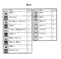
また、図25下図の表示例にあるように、気持ち・感情等の記号群に予め気持ち・感情の起伏を表す指標を付与しておくと、気持ち・感情の起伏を表すグラフを生成することが可能である。 In addition, as shown in the display example in the lower part of FIG. 25, if an index representing the undulations of feelings / emotions is given in advance to the symbol group of feelings / emotions, a graph representing the undulations of feelings / emotions can be generated. Is possible.
図26に図25のコメント候補表示部1061中に表示されているコメント候補の内容および気持ち・感情の起伏を表すスコアの例を示す。コメント候補は図25及び図26中に記載されているものが全てではなく、感情を示すものなど様々なものが含まれる。また、スコアの与え方も気持ち・感情の起伏を表すことができればどのような方法でもかまわない。 FIG. 26 shows an example of a score representing the contents of the comment candidates and the feeling / feeling undulations displayed in the comment candidate display section 1061 of FIG. The comment candidates are not all those shown in FIGS. 25 and 26, but include various things such as those showing emotions. The method of giving the score can be any method as long as it can express the undulations of feelings and emotions.
このように、利用者の気持ち・感情を表す記号を、シーン領域データ、イベントデータ、PC利用状況に関するデータ及びスケジュールデータと併せて用いることに用いることにより、実際の行動における気持ちや感情を容易に記録することが可能となり、利用者の入力負担軽減を実現することができる。 In this way, by using symbols representing the user's feelings and feelings in combination with scene area data, event data, PC usage status data and schedule data, the feelings and feelings in actual behavior can be easily obtained. It becomes possible to record, and it is possible to reduce the input burden on the user.
以上、本発明の実施形態について説明したが、本発明は上記実施形態に限定されるものでなく、種種変形実施可能であり、上述した各実施形態を適宜組み合わせることが可能であることは、当業者に理解されよう。 Although the embodiments of the present invention have been described above, the present invention is not limited to the above-described embodiments, and various modifications can be made, and it is possible to appropriately combine the above-described embodiments. It will be understood by the contractor.
1 腕輪型センサノード
102 基地局
103 クライアント計算機
104 サーバ
200 データ集計部
300 シーン分割部
400 シーン列挙部
500 行動獲得部
600 データ格納部
1031 表示部
1032 入力部
DESCRIPTION OF
Claims (13)
ネットワークを介して上記サーバに接続され、受信する上記センシングデータを上記サーバに送信する基地局と、
上記センシングデータを蓄積するデータ格納部と、上記データ格納部に蓄積されたセンシングデータから上記監視対象の動作状態を検出するシーン分割部と、上記データ格納部に格納されるシーン判定ルールに基づいて上記動作状態から上記監視対象の行動内容の候補を複数算出するシーン列挙部と、接続される表示部に上記複数の行動内容の候補を表示し、上記表示された複数の行動内容の候補から特定の行動内容が選択されると、上記監視対象の行動内容を確定して上記データ格納部に格納する行動獲得部と、を有するサーバと、
を備える行動記録入力支援システム。 A sensor node that includes a sensor and a communication unit that transmits sensing data acquired by the sensor to a server;
A base station connected to the server via a network and transmitting the sensing data received to the server;
Based on a data storage unit that accumulates the sensing data, a scene division unit that detects an operation state of the monitoring target from the sensing data accumulated in the data storage unit, and a scene determination rule stored in the data storage unit A scene enumeration unit that calculates a plurality of behavior content candidates to be monitored from the operation state, and the plurality of behavior content candidates displayed on a connected display unit, and specified from the displayed plurality of behavior content candidates When the action content is selected, an action acquisition unit that determines the action content to be monitored and stores it in the data storage unit,
An action record input support system comprising:
上記シーン列挙部は、上記複数の候補それぞれの確信度を算出し、
上記行動獲得部は、時間間隔の異なる上記行動内容の候補を、上記確信度とともに上記表示部に表示する行動記録入力支援システム。 The action record input support system according to claim 1,
The scene enumeration unit calculates a certainty factor for each of the plurality of candidates,
The behavior acquisition input support system, wherein the behavior acquisition unit displays the behavior content candidates having different time intervals together with the certainty factor on the display unit.
上記シーン分割部は、上記動作状態と次の動作状態に挟まれた期間をシーン領域として抽出し、上記シーン領域ごとに上記センシングデータの時系列的な変化点を検出し、当該変化点から次の変化点までを運動単位とするシーン断片を抽出する行動記録入力支援システム。 The action record input support system according to claim 1,
The scene dividing unit extracts a period between the operation state and the next operation state as a scene region, detects a time-series change point of the sensing data for each scene region, and then performs a next step from the change point. An action record input support system that extracts scene fragments whose motion unit is up to the change point of the.
上記シーン判定ルールは、条件テーブルと結論テーブルからなり、
上記条件テーブルと上記結論テーブルは、ルールIDにより関連づけられ、
上記条件テーブルは、上記監視対象の動作状態を示すシーン領域、上記シーン領域を構成し運動単位を示すシーン断片、上記監視対象の行動記録、時間情報及びそれらの出現順序からなり、
上記結論テーブルは、上記出現順序、行動内容、及び確信度からなる行動記録入力支援システム。 The action record input support system according to claim 1,
The scene judgment rule consists of a condition table and a conclusion table.
The condition table and the conclusion table are related by a rule ID,
The condition table is composed of a scene area indicating the operation state of the monitoring target, a scene fragment constituting the scene area and indicating a motion unit, action recording of the monitoring target, time information, and their appearance order.
The conclusion table is an action record input support system including the order of appearance, action contents, and certainty.
上記データ格納部は、外部機器を通じて入力されるデータをイベントデータとして記録し、
上記行動獲得部は、上記行動内容と時間軸を一致させて上記イベントデータを上記表示部に表示し、上記表示されたイベントデータが選択されると、上記確定された行動内容とともに上記選択されたイベントデータが表示される行動記録入力支援システム。 The action record input support system according to claim 1,
The data storage unit records data input through an external device as event data,
The action acquisition unit displays the event data on the display unit with the action content and the time axis matched. When the displayed event data is selected, the action acquisition unit is selected together with the confirmed action content. An action record input support system that displays event data.
上記行動獲得部は、上記表示部に、上記行動内容の時間幅を調整するための目盛りを表示する行動記録入力支援システム。 The action record input support system according to claim 1,
The behavior acquisition input support system, wherein the behavior acquisition unit displays a scale for adjusting a time width of the behavior content on the display unit.
上記監視対象が人である場合であって、
上記データ格納部には、上記人の気持ちあるいは感情を示す記号が格納され、
上記行動獲得部は、上記記号を上記表示部に表示し、上記表示された記号が選択されると、上記選択された記号に対応する指標に基づき、上記人の気持ちあるいは感情を時系列にグラフ表示する行動記録入力支援システム。 The action record input support system according to claim 1,
When the monitoring target is a person,
The data storage unit stores a symbol indicating the feeling or emotion of the person,
The action acquisition unit displays the symbol on the display unit, and when the displayed symbol is selected, the person's feelings or emotions are graphed in time series based on an index corresponding to the selected symbol. Action record input support system to display.
上記生体情報を蓄積するデータ格納部と、
上記生体情報から上記監視対象の動作状態を検出するシーン分割部と、
上記データ格納部に格納されるシーン判定ルールに基づいて上記動作状態から上記監視対象の行動内容の候補を複数算出するシーン列挙部と、
接続される表示部に上記複数の行動内容の候補を表示し、上記表示された複数の行動内容の候補から特定の行動内容が選択されると、上記監視対象の行動内容を確定して上記データ格納部に格納する行動獲得部と、
を備えるサーバ。 A communication unit that receives biological information acquired by a sensor node attached to a monitoring target;
A data storage unit for storing the biological information;
A scene division unit for detecting the operation state of the monitoring target from the biological information;
A scene enumeration unit that calculates a plurality of behavior content candidates for the monitoring target from the operation state based on a scene determination rule stored in the data storage unit;
The plurality of action content candidates are displayed on the connected display unit, and when a specific action content is selected from the displayed plurality of action content candidates, the action content to be monitored is confirmed and the data An action acquisition unit stored in the storage unit;
A server comprising
上記シーン列挙部は、上記複数の候補それぞれの確信度を算出し、
上記行動獲得部は、時間間隔の異なる上記行動内容の候補を、上記確信度とともに上記表示部に表示するサーバ。 The server according to claim 8, wherein
The scene enumeration unit calculates a certainty factor for each of the plurality of candidates,
The said action acquisition part is a server which displays the candidate of the said action content from which a time interval differs on the said display part with the said certainty factor.
上記シーン分割部は、上記動作状態と次の動作状態に挟まれた期間をシーン領域として抽出し、上記シーン領域ごとに上記生体情報の時系列的な変化点を検出し、当該変化点から次の変化点までを運動単位とするシーン断片を抽出するサーバ。 The server according to claim 8, wherein
The scene dividing unit extracts a period between the operation state and the next operation state as a scene region, detects a time-series change point of the biological information for each scene region, and then performs a next step from the change point. A server that extracts scene fragments whose motion unit is up to the change point.
上記シーン判定ルールは、条件テーブルと結論テーブルからなり、
上記条件テーブルと上記結論テーブルは、ルールIDにより関連づけられ、
上記条件テーブルは、上記監視対象の動作状態を示すシーン領域、上記シーン領域を構成し運動単位を示すシーン断片、上記監視対象の行動記録、時間情報及びそれらの出現順序からなり、
上記結論テーブルは、上記出現順序、行動内容、及び確信度からなるサーバ。 The server according to claim 8, wherein
The scene judgment rule consists of a condition table and a conclusion table.
The condition table and the conclusion table are related by a rule ID,
The condition table is composed of a scene area indicating the operation state of the monitoring target, a scene fragment constituting the scene area and indicating a motion unit, action recording of the monitoring target, time information, and their appearance order.
The conclusion table is a server comprising the order of appearance, action content, and certainty.
上記センサノードは、上記センサが取得したセンシングデータを上記サーバに送信し、
上記サーバは、上記センシングデータを蓄積し、上記センシングデータから上記監視対象の動作状態を検出し、上記サーバに格納されるシーン判定ルールに基づいて上記動作状態から上記監視対象の行動内容の候補を複数算出し、接続される表示部に上記複数の行動内容の候補を表示し、上記表示された複数の行動内容の候補から特定の行動内容が選択されると、上記監視対象の行動内容を確定して上記サーバに格納する行動記録入力支援方法。 An action record input support method executed by a system including a sensor node that is attached to a monitoring target and acquires sensing data, and a server that analyzes the sensing data,
The sensor node transmits sensing data acquired by the sensor to the server,
The server accumulates the sensing data, detects the operation state of the monitoring target from the sensing data, and selects the action content candidate of the monitoring target from the operation state based on a scene determination rule stored in the server. Multiple calculations are performed, the plurality of action content candidates are displayed on the connected display unit, and when a specific action content is selected from the displayed plurality of action content candidates, the action content to be monitored is determined. The action record input support method stored in the server.
上記サーバは、上記複数の候補それぞれの確信度を算出し、時間間隔の異なる上記行動内容の候補を、上記確信度とともに上記表示部に表示する行動記録入力支援方法。 The action record input support method according to claim 12,
The server calculates the certainty factor of each of the plurality of candidates, and displays the action content candidates having different time intervals on the display unit together with the certainty factor.
Priority Applications (1)
| Application Number | Priority Date | Filing Date | Title |
|---|---|---|---|
| JP2008321724A JP5372487B2 (en) | 2008-12-18 | 2008-12-18 | Action record input support system and server |
Applications Claiming Priority (1)
| Application Number | Priority Date | Filing Date | Title |
|---|---|---|---|
| JP2008321724A JP5372487B2 (en) | 2008-12-18 | 2008-12-18 | Action record input support system and server |
Publications (2)
| Publication Number | Publication Date |
|---|---|
| JP2010146221A true JP2010146221A (en) | 2010-07-01 |
| JP5372487B2 JP5372487B2 (en) | 2013-12-18 |
Family
ID=42566613
Family Applications (1)
| Application Number | Title | Priority Date | Filing Date |
|---|---|---|---|
| JP2008321724A Expired - Fee Related JP5372487B2 (en) | 2008-12-18 | 2008-12-18 | Action record input support system and server |
Country Status (1)
| Country | Link |
|---|---|
| JP (1) | JP5372487B2 (en) |
Cited By (10)
| Publication number | Priority date | Publication date | Assignee | Title |
|---|---|---|---|---|
| JP2012146202A (en) * | 2011-01-13 | 2012-08-02 | Nippon Steel Corp | Workflow management device, workflow management method, and computer program |
| WO2013187035A1 (en) * | 2012-06-12 | 2013-12-19 | 日本電気株式会社 | Behavior discrimination system, behavior discrimination method, terminal, server, and computer program |
| JP2015022482A (en) * | 2013-07-18 | 2015-02-02 | 日本電信電話株式会社 | Living condition estimation system and living condition estimation method |
| US20160026349A1 (en) * | 2011-06-13 | 2016-01-28 | Sony Corporation | Information processing device, information processing method, and computer program |
| JP2016035760A (en) * | 2015-10-07 | 2016-03-17 | ソニー株式会社 | Information processor, information processing method and computer program |
| JP2016212793A (en) * | 2015-05-13 | 2016-12-15 | ヤフー株式会社 | Prediction device, terminal, prediction method and prediction program |
| JP2017016704A (en) * | 2016-10-07 | 2017-01-19 | ソニー株式会社 | Information processing device, information processing method and computer program |
| JP2017146798A (en) * | 2016-02-17 | 2017-08-24 | ソフトバンク株式会社 | Display control device and program |
| JP2017152003A (en) * | 2017-03-23 | 2017-08-31 | セイコーエプソン株式会社 | Behavior recording device, behavior recording method, and behavior recording program |
| WO2024023897A1 (en) * | 2022-07-25 | 2024-02-01 | 日本電気株式会社 | Information processing device, information processing method, and recording medium |
Citations (5)
| Publication number | Priority date | Publication date | Assignee | Title |
|---|---|---|---|---|
| JP2004038580A (en) * | 2002-07-03 | 2004-02-05 | Ricoh Co Ltd | Schedule management system |
| JP2005062963A (en) * | 2003-08-18 | 2005-03-10 | Toshiba Corp | Time series action pattern display device, method, and program |
| JP2005165446A (en) * | 2003-11-28 | 2005-06-23 | Toshiba Corp | Action event information generating device and method and action event information collecting device |
| JP2006134080A (en) * | 2004-11-05 | 2006-05-25 | Ntt Docomo Inc | Portable terminal, and individual adaptive context acquiring method |
| JP2006134343A (en) * | 2005-11-18 | 2006-05-25 | Fujitsu Ltd | Schedule display device, schedule display method and recording medium |
-
2008
- 2008-12-18 JP JP2008321724A patent/JP5372487B2/en not_active Expired - Fee Related
Patent Citations (5)
| Publication number | Priority date | Publication date | Assignee | Title |
|---|---|---|---|---|
| JP2004038580A (en) * | 2002-07-03 | 2004-02-05 | Ricoh Co Ltd | Schedule management system |
| JP2005062963A (en) * | 2003-08-18 | 2005-03-10 | Toshiba Corp | Time series action pattern display device, method, and program |
| JP2005165446A (en) * | 2003-11-28 | 2005-06-23 | Toshiba Corp | Action event information generating device and method and action event information collecting device |
| JP2006134080A (en) * | 2004-11-05 | 2006-05-25 | Ntt Docomo Inc | Portable terminal, and individual adaptive context acquiring method |
| JP2006134343A (en) * | 2005-11-18 | 2006-05-25 | Fujitsu Ltd | Schedule display device, schedule display method and recording medium |
Cited By (13)
| Publication number | Priority date | Publication date | Assignee | Title |
|---|---|---|---|---|
| JP2012146202A (en) * | 2011-01-13 | 2012-08-02 | Nippon Steel Corp | Workflow management device, workflow management method, and computer program |
| CN106202528A (en) * | 2011-06-13 | 2016-12-07 | 索尼公司 | Information processor, information processing method and computer program |
| US20160026349A1 (en) * | 2011-06-13 | 2016-01-28 | Sony Corporation | Information processing device, information processing method, and computer program |
| US10740057B2 (en) | 2011-06-13 | 2020-08-11 | Sony Corporation | Information processing device, information processing method, and computer program |
| JPWO2013187035A1 (en) * | 2012-06-12 | 2016-02-04 | 日本電気株式会社 | Action identification system, action identification method, terminal, server, and computer program |
| WO2013187035A1 (en) * | 2012-06-12 | 2013-12-19 | 日本電気株式会社 | Behavior discrimination system, behavior discrimination method, terminal, server, and computer program |
| JP2015022482A (en) * | 2013-07-18 | 2015-02-02 | 日本電信電話株式会社 | Living condition estimation system and living condition estimation method |
| JP2016212793A (en) * | 2015-05-13 | 2016-12-15 | ヤフー株式会社 | Prediction device, terminal, prediction method and prediction program |
| JP2016035760A (en) * | 2015-10-07 | 2016-03-17 | ソニー株式会社 | Information processor, information processing method and computer program |
| JP2017146798A (en) * | 2016-02-17 | 2017-08-24 | ソフトバンク株式会社 | Display control device and program |
| JP2017016704A (en) * | 2016-10-07 | 2017-01-19 | ソニー株式会社 | Information processing device, information processing method and computer program |
| JP2017152003A (en) * | 2017-03-23 | 2017-08-31 | セイコーエプソン株式会社 | Behavior recording device, behavior recording method, and behavior recording program |
| WO2024023897A1 (en) * | 2022-07-25 | 2024-02-01 | 日本電気株式会社 | Information processing device, information processing method, and recording medium |
Also Published As
| Publication number | Publication date |
|---|---|
| JP5372487B2 (en) | 2013-12-18 |
Similar Documents
| Publication | Publication Date | Title |
|---|---|---|
| JP5372487B2 (en) | Action record input support system and server | |
| JP5250827B2 (en) | Action history generation method and action history generation system | |
| US11550400B2 (en) | Methods and systems for monitoring and influencing gesture-based behaviors | |
| US9750433B2 (en) | Using health monitor data to detect macro and micro habits with a behavioral model | |
| JP5466713B2 (en) | Life pattern classification device and life pattern classification system | |
| JP5216140B2 (en) | Action suggestion apparatus and method | |
| US20190392727A1 (en) | Sedentary notification management system for portable biometric devices | |
| EP3014905B1 (en) | User activity tracking system and device | |
| US20170243508A1 (en) | Generation of sedentary time information by activity tracking device | |
| JP2010146223A (en) | Behavior extraction system, behavior extraction method, and server | |
| JP5361018B2 (en) | Life visualization system, server, and life data processing method | |
| US20140099614A1 (en) | Method for delivering behavior change directives to a user | |
| JP5767833B2 (en) | Saddle position estimation apparatus, heel position estimation system, and heel position estimation method | |
| CN104434314A (en) | Portable Monitoring Devices and Methods of Operating Same | |
| JP5199152B2 (en) | Behavior prediction method and behavior prediction system | |
| CN107430426A (en) | Automatically change the healthy wearable thing that sensor reads timing | |
| CN106645978A (en) | Wearing state detecting method and detecting device for intelligent wearable equipment | |
| US20040210117A1 (en) | Behavior control support apparatus and method | |
| US20170238881A1 (en) | Periodic inactivity alerts and achievement messages | |
| JP6423017B2 (en) | Psychological state measurement system | |
| CN105996984A (en) | Method using wearable electronic device to detect sedentary time period | |
| JP2016010562A (en) | Data analyzer, data analysis method, and data analysis program | |
| Van Laerhoven et al. | Wear is your mobile? Investigating phone carrying and use habits with a wearable device | |
| CN113546396A (en) | Data processing system and method based on big data | |
| US10327696B2 (en) | Action notification system, exercise information measurement apparatus, electronic device, action notification method, and action notification program |
Legal Events
| Date | Code | Title | Description |
|---|---|---|---|
| A621 | Written request for application examination |
Free format text: JAPANESE INTERMEDIATE CODE: A621 Effective date: 20111124 |
|
| A977 | Report on retrieval |
Free format text: JAPANESE INTERMEDIATE CODE: A971007 Effective date: 20130311 |
|
| A131 | Notification of reasons for refusal |
Free format text: JAPANESE INTERMEDIATE CODE: A131 Effective date: 20130319 |
|
| A521 | Written amendment |
Free format text: JAPANESE INTERMEDIATE CODE: A523 Effective date: 20130514 |
|
| A131 | Notification of reasons for refusal |
Free format text: JAPANESE INTERMEDIATE CODE: A131 Effective date: 20130611 |
|
| A521 | Written amendment |
Free format text: JAPANESE INTERMEDIATE CODE: A523 Effective date: 20130722 |
|
| TRDD | Decision of grant or rejection written | ||
| A01 | Written decision to grant a patent or to grant a registration (utility model) |
Free format text: JAPANESE INTERMEDIATE CODE: A01 Effective date: 20130820 |
|
| A61 | First payment of annual fees (during grant procedure) |
Free format text: JAPANESE INTERMEDIATE CODE: A61 Effective date: 20130918 |
|
| LAPS | Cancellation because of no payment of annual fees |