JP2010142843A - Welding material consisting of austenitic stainless steel, and method for preventive maintenance of stress corrosion cracking and intergranular corrosion using the same - Google Patents
Welding material consisting of austenitic stainless steel, and method for preventive maintenance of stress corrosion cracking and intergranular corrosion using the same Download PDFInfo
- Publication number
- JP2010142843A JP2010142843A JP2008322639A JP2008322639A JP2010142843A JP 2010142843 A JP2010142843 A JP 2010142843A JP 2008322639 A JP2008322639 A JP 2008322639A JP 2008322639 A JP2008322639 A JP 2008322639A JP 2010142843 A JP2010142843 A JP 2010142843A
- Authority
- JP
- Japan
- Prior art keywords
- welding
- less
- stainless steel
- austenitic stainless
- welding material
- Prior art date
- Legal status (The legal status is an assumption and is not a legal conclusion. Google has not performed a legal analysis and makes no representation as to the accuracy of the status listed.)
- Granted
Links
- 238000003466 welding Methods 0.000 title claims abstract description 162
- 239000000463 material Substances 0.000 title claims abstract description 154
- 230000007797 corrosion Effects 0.000 title claims abstract description 139
- 238000005260 corrosion Methods 0.000 title claims abstract description 139
- 238000005336 cracking Methods 0.000 title claims abstract description 65
- 229910000963 austenitic stainless steel Inorganic materials 0.000 title claims abstract description 52
- 238000000034 method Methods 0.000 title claims abstract description 51
- 238000012423 maintenance Methods 0.000 title claims abstract description 26
- 230000003449 preventive effect Effects 0.000 title claims abstract description 25
- 229910052757 nitrogen Inorganic materials 0.000 claims abstract description 22
- 229910052698 phosphorus Inorganic materials 0.000 claims abstract description 22
- 229910052799 carbon Inorganic materials 0.000 claims abstract description 21
- 229910052717 sulfur Inorganic materials 0.000 claims abstract description 21
- 229910052804 chromium Inorganic materials 0.000 claims abstract description 7
- 229910052748 manganese Inorganic materials 0.000 claims abstract description 6
- 229910052759 nickel Inorganic materials 0.000 claims abstract description 6
- 229910052760 oxygen Inorganic materials 0.000 claims abstract description 6
- 229910052710 silicon Inorganic materials 0.000 claims abstract description 6
- 239000012530 fluid Substances 0.000 claims description 8
- 230000002950 deficient Effects 0.000 claims description 6
- 229910000831 Steel Inorganic materials 0.000 description 24
- 239000010959 steel Substances 0.000 description 24
- 238000012360 testing method Methods 0.000 description 24
- 239000000126 substance Substances 0.000 description 23
- 239000000203 mixture Substances 0.000 description 21
- 239000012535 impurity Substances 0.000 description 19
- 229910052751 metal Inorganic materials 0.000 description 19
- XLYOFNOQVPJJNP-UHFFFAOYSA-N water Substances O XLYOFNOQVPJJNP-UHFFFAOYSA-N 0.000 description 19
- 239000002184 metal Substances 0.000 description 18
- 239000011651 chromium Substances 0.000 description 17
- GRYLNZFGIOXLOG-UHFFFAOYSA-N Nitric acid Chemical compound O[N+]([O-])=O GRYLNZFGIOXLOG-UHFFFAOYSA-N 0.000 description 16
- 229910017604 nitric acid Inorganic materials 0.000 description 16
- 239000000243 solution Substances 0.000 description 16
- 230000008439 repair process Effects 0.000 description 13
- 206010070834 Sensitisation Diseases 0.000 description 10
- 230000008313 sensitization Effects 0.000 description 10
- 238000009835 boiling Methods 0.000 description 9
- 230000000694 effects Effects 0.000 description 9
- 229910001220 stainless steel Inorganic materials 0.000 description 8
- 229910001566 austenite Inorganic materials 0.000 description 7
- 238000001556 precipitation Methods 0.000 description 7
- 229910045601 alloy Inorganic materials 0.000 description 6
- 239000000956 alloy Substances 0.000 description 6
- 238000004458 analytical method Methods 0.000 description 6
- 230000015572 biosynthetic process Effects 0.000 description 6
- 238000011161 development Methods 0.000 description 6
- XEEYBQQBJWHFJM-UHFFFAOYSA-N iron Substances [Fe] XEEYBQQBJWHFJM-UHFFFAOYSA-N 0.000 description 6
- 239000010935 stainless steel Substances 0.000 description 6
- 230000002411 adverse Effects 0.000 description 5
- 238000005253 cladding Methods 0.000 description 5
- 230000007547 defect Effects 0.000 description 5
- 238000005516 engineering process Methods 0.000 description 5
- 238000010438 heat treatment Methods 0.000 description 5
- 150000002500 ions Chemical class 0.000 description 5
- 238000012546 transfer Methods 0.000 description 5
- 229910000859 α-Fe Inorganic materials 0.000 description 5
- OKTJSMMVPCPJKN-UHFFFAOYSA-N Carbon Chemical compound [C] OKTJSMMVPCPJKN-UHFFFAOYSA-N 0.000 description 4
- 229910010413 TiO 2 Inorganic materials 0.000 description 4
- ATJFFYVFTNAWJD-UHFFFAOYSA-N Tin Chemical compound [Sn] ATJFFYVFTNAWJD-UHFFFAOYSA-N 0.000 description 4
- 150000001875 compounds Chemical class 0.000 description 4
- 238000004519 manufacturing process Methods 0.000 description 4
- 239000012071 phase Substances 0.000 description 4
- 238000012545 processing Methods 0.000 description 4
- 238000012958 reprocessing Methods 0.000 description 4
- ZOXJGFHDIHLPTG-UHFFFAOYSA-N Boron Chemical compound [B] ZOXJGFHDIHLPTG-UHFFFAOYSA-N 0.000 description 3
- 239000010953 base metal Substances 0.000 description 3
- 229910052796 boron Inorganic materials 0.000 description 3
- 230000006835 compression Effects 0.000 description 3
- 238000007906 compression Methods 0.000 description 3
- 238000005304 joining Methods 0.000 description 3
- 239000007788 liquid Substances 0.000 description 3
- 238000002844 melting Methods 0.000 description 3
- 230000008018 melting Effects 0.000 description 3
- 229910021645 metal ion Inorganic materials 0.000 description 3
- 230000001590 oxidative effect Effects 0.000 description 3
- 239000002244 precipitate Substances 0.000 description 3
- 239000006104 solid solution Substances 0.000 description 3
- 238000007711 solidification Methods 0.000 description 3
- 230000008023 solidification Effects 0.000 description 3
- 230000000087 stabilizing effect Effects 0.000 description 3
- -1 TiC Chemical class 0.000 description 2
- 239000011324 bead Substances 0.000 description 2
- 238000006243 chemical reaction Methods 0.000 description 2
- UFGZSIPAQKLCGR-UHFFFAOYSA-N chromium carbide Chemical compound [Cr]#C[Cr]C#[Cr] UFGZSIPAQKLCGR-UHFFFAOYSA-N 0.000 description 2
- 230000000052 comparative effect Effects 0.000 description 2
- 230000007423 decrease Effects 0.000 description 2
- 238000010586 diagram Methods 0.000 description 2
- 238000009792 diffusion process Methods 0.000 description 2
- 238000007654 immersion Methods 0.000 description 2
- 230000006698 induction Effects 0.000 description 2
- 229910052742 iron Inorganic materials 0.000 description 2
- 150000001247 metal acetylides Chemical class 0.000 description 2
- 230000003647 oxidation Effects 0.000 description 2
- 238000007254 oxidation reaction Methods 0.000 description 2
- 230000002265 prevention Effects 0.000 description 2
- 230000008569 process Effects 0.000 description 2
- 239000002994 raw material Substances 0.000 description 2
- 230000009467 reduction Effects 0.000 description 2
- 238000007670 refining Methods 0.000 description 2
- 230000035945 sensitivity Effects 0.000 description 2
- 239000007790 solid phase Substances 0.000 description 2
- 239000002915 spent fuel radioactive waste Substances 0.000 description 2
- 238000009628 steelmaking Methods 0.000 description 2
- 229910003470 tongbaite Inorganic materials 0.000 description 2
- 230000009466 transformation Effects 0.000 description 2
- 229910000967 As alloy Inorganic materials 0.000 description 1
- VYZAMTAEIAYCRO-UHFFFAOYSA-N Chromium Chemical compound [Cr] VYZAMTAEIAYCRO-UHFFFAOYSA-N 0.000 description 1
- 230000009471 action Effects 0.000 description 1
- QVGXLLKOCUKJST-UHFFFAOYSA-N atomic oxygen Chemical compound [O] QVGXLLKOCUKJST-UHFFFAOYSA-N 0.000 description 1
- 230000033228 biological regulation Effects 0.000 description 1
- 239000005539 carbonized material Substances 0.000 description 1
- 238000005266 casting Methods 0.000 description 1
- 230000008859 change Effects 0.000 description 1
- 239000011248 coating agent Substances 0.000 description 1
- 238000000576 coating method Methods 0.000 description 1
- 238000010276 construction Methods 0.000 description 1
- 230000008602 contraction Effects 0.000 description 1
- 238000001816 cooling Methods 0.000 description 1
- 239000000498 cooling water Substances 0.000 description 1
- 239000013078 crystal Substances 0.000 description 1
- 238000001514 detection method Methods 0.000 description 1
- 230000006866 deterioration Effects 0.000 description 1
- 238000011978 dissolution method Methods 0.000 description 1
- 230000001814 effect on stress Effects 0.000 description 1
- 238000010894 electron beam technology Methods 0.000 description 1
- 230000002708 enhancing effect Effects 0.000 description 1
- 238000011156 evaluation Methods 0.000 description 1
- 239000000835 fiber Substances 0.000 description 1
- 239000000945 filler Substances 0.000 description 1
- 230000004907 flux Effects 0.000 description 1
- 238000005242 forging Methods 0.000 description 1
- 230000006870 function Effects 0.000 description 1
- 239000007789 gas Substances 0.000 description 1
- 238000001036 glow-discharge mass spectrometry Methods 0.000 description 1
- 229910002804 graphite Inorganic materials 0.000 description 1
- 239000010439 graphite Substances 0.000 description 1
- 239000003112 inhibitor Substances 0.000 description 1
- 238000011835 investigation Methods 0.000 description 1
- 230000007774 longterm Effects 0.000 description 1
- 238000003754 machining Methods 0.000 description 1
- 238000012986 modification Methods 0.000 description 1
- 230000004048 modification Effects 0.000 description 1
- 150000002926 oxygen Chemical class 0.000 description 1
- 239000001301 oxygen Substances 0.000 description 1
- 238000010248 power generation Methods 0.000 description 1
- 238000000746 purification Methods 0.000 description 1
- 238000007712 rapid solidification Methods 0.000 description 1
- 239000007787 solid Substances 0.000 description 1
- 239000000758 substrate Substances 0.000 description 1
- 230000008961 swelling Effects 0.000 description 1
- 150000003568 thioethers Chemical class 0.000 description 1
- 238000005491 wire drawing Methods 0.000 description 1
- 210000002268 wool Anatomy 0.000 description 1
Images


Classifications
-
- B—PERFORMING OPERATIONS; TRANSPORTING
- B23—MACHINE TOOLS; METAL-WORKING NOT OTHERWISE PROVIDED FOR
- B23K—SOLDERING OR UNSOLDERING; WELDING; CLADDING OR PLATING BY SOLDERING OR WELDING; CUTTING BY APPLYING HEAT LOCALLY, e.g. FLAME CUTTING; WORKING BY LASER BEAM
- B23K35/00—Rods, electrodes, materials, or media, for use in soldering, welding, or cutting
- B23K35/22—Rods, electrodes, materials, or media, for use in soldering, welding, or cutting characterised by the composition or nature of the material
- B23K35/24—Selection of soldering or welding materials proper
- B23K35/30—Selection of soldering or welding materials proper with the principal constituent melting at less than 1550 degrees C
- B23K35/3053—Fe as the principal constituent
-
- B—PERFORMING OPERATIONS; TRANSPORTING
- B23—MACHINE TOOLS; METAL-WORKING NOT OTHERWISE PROVIDED FOR
- B23K—SOLDERING OR UNSOLDERING; WELDING; CLADDING OR PLATING BY SOLDERING OR WELDING; CUTTING BY APPLYING HEAT LOCALLY, e.g. FLAME CUTTING; WORKING BY LASER BEAM
- B23K31/00—Processes relevant to this subclass, specially adapted for particular articles or purposes, but not covered by only one of the preceding main groups
- B23K31/12—Processes relevant to this subclass, specially adapted for particular articles or purposes, but not covered by only one of the preceding main groups relating to investigating the properties, e.g. the weldability, of materials
-
- B—PERFORMING OPERATIONS; TRANSPORTING
- B23—MACHINE TOOLS; METAL-WORKING NOT OTHERWISE PROVIDED FOR
- B23K—SOLDERING OR UNSOLDERING; WELDING; CLADDING OR PLATING BY SOLDERING OR WELDING; CUTTING BY APPLYING HEAT LOCALLY, e.g. FLAME CUTTING; WORKING BY LASER BEAM
- B23K9/00—Arc welding or cutting
- B23K9/04—Welding for other purposes than joining, e.g. built-up welding
-
- B—PERFORMING OPERATIONS; TRANSPORTING
- B23—MACHINE TOOLS; METAL-WORKING NOT OTHERWISE PROVIDED FOR
- B23K—SOLDERING OR UNSOLDERING; WELDING; CLADDING OR PLATING BY SOLDERING OR WELDING; CUTTING BY APPLYING HEAT LOCALLY, e.g. FLAME CUTTING; WORKING BY LASER BEAM
- B23K9/00—Arc welding or cutting
- B23K9/23—Arc welding or cutting taking account of the properties of the materials to be welded
-
- C—CHEMISTRY; METALLURGY
- C21—METALLURGY OF IRON
- C21D—MODIFYING THE PHYSICAL STRUCTURE OF FERROUS METALS; GENERAL DEVICES FOR HEAT TREATMENT OF FERROUS OR NON-FERROUS METALS OR ALLOYS; MAKING METAL MALLEABLE, e.g. BY DECARBURISATION OR TEMPERING
- C21D9/00—Heat treatment, e.g. annealing, hardening, quenching or tempering, adapted for particular articles; Furnaces therefor
- C21D9/50—Heat treatment, e.g. annealing, hardening, quenching or tempering, adapted for particular articles; Furnaces therefor for welded joints
- C21D9/505—Cooling thereof
-
- C—CHEMISTRY; METALLURGY
- C22—METALLURGY; FERROUS OR NON-FERROUS ALLOYS; TREATMENT OF ALLOYS OR NON-FERROUS METALS
- C22C—ALLOYS
- C22C38/00—Ferrous alloys, e.g. steel alloys
- C22C38/001—Ferrous alloys, e.g. steel alloys containing N
-
- C—CHEMISTRY; METALLURGY
- C22—METALLURGY; FERROUS OR NON-FERROUS ALLOYS; TREATMENT OF ALLOYS OR NON-FERROUS METALS
- C22C—ALLOYS
- C22C38/00—Ferrous alloys, e.g. steel alloys
- C22C38/004—Very low carbon steels, i.e. having a carbon content of less than 0,01%
-
- C—CHEMISTRY; METALLURGY
- C22—METALLURGY; FERROUS OR NON-FERROUS ALLOYS; TREATMENT OF ALLOYS OR NON-FERROUS METALS
- C22C—ALLOYS
- C22C38/00—Ferrous alloys, e.g. steel alloys
- C22C38/02—Ferrous alloys, e.g. steel alloys containing silicon
-
- C—CHEMISTRY; METALLURGY
- C22—METALLURGY; FERROUS OR NON-FERROUS ALLOYS; TREATMENT OF ALLOYS OR NON-FERROUS METALS
- C22C—ALLOYS
- C22C38/00—Ferrous alloys, e.g. steel alloys
- C22C38/04—Ferrous alloys, e.g. steel alloys containing manganese
-
- C—CHEMISTRY; METALLURGY
- C22—METALLURGY; FERROUS OR NON-FERROUS ALLOYS; TREATMENT OF ALLOYS OR NON-FERROUS METALS
- C22C—ALLOYS
- C22C38/00—Ferrous alloys, e.g. steel alloys
- C22C38/18—Ferrous alloys, e.g. steel alloys containing chromium
- C22C38/40—Ferrous alloys, e.g. steel alloys containing chromium with nickel
- C22C38/50—Ferrous alloys, e.g. steel alloys containing chromium with nickel with titanium or zirconium
-
- C—CHEMISTRY; METALLURGY
- C22—METALLURGY; FERROUS OR NON-FERROUS ALLOYS; TREATMENT OF ALLOYS OR NON-FERROUS METALS
- C22C—ALLOYS
- C22C38/00—Ferrous alloys, e.g. steel alloys
- C22C38/18—Ferrous alloys, e.g. steel alloys containing chromium
- C22C38/40—Ferrous alloys, e.g. steel alloys containing chromium with nickel
- C22C38/54—Ferrous alloys, e.g. steel alloys containing chromium with nickel with boron
-
- F—MECHANICAL ENGINEERING; LIGHTING; HEATING; WEAPONS; BLASTING
- F16—ENGINEERING ELEMENTS AND UNITS; GENERAL MEASURES FOR PRODUCING AND MAINTAINING EFFECTIVE FUNCTIONING OF MACHINES OR INSTALLATIONS; THERMAL INSULATION IN GENERAL
- F16J—PISTONS; CYLINDERS; SEALINGS
- F16J12/00—Pressure vessels in general
-
- C—CHEMISTRY; METALLURGY
- C21—METALLURGY OF IRON
- C21D—MODIFYING THE PHYSICAL STRUCTURE OF FERROUS METALS; GENERAL DEVICES FOR HEAT TREATMENT OF FERROUS OR NON-FERROUS METALS OR ALLOYS; MAKING METAL MALLEABLE, e.g. BY DECARBURISATION OR TEMPERING
- C21D2211/00—Microstructure comprising significant phases
- C21D2211/001—Austenite
-
- C—CHEMISTRY; METALLURGY
- C21—METALLURGY OF IRON
- C21D—MODIFYING THE PHYSICAL STRUCTURE OF FERROUS METALS; GENERAL DEVICES FOR HEAT TREATMENT OF FERROUS OR NON-FERROUS METALS OR ALLOYS; MAKING METAL MALLEABLE, e.g. BY DECARBURISATION OR TEMPERING
- C21D2251/00—Treating composite or clad material
- C21D2251/04—Welded or brazed overlays
Abstract
Description
本発明は、オーステナイト系ステンレス鋼からなる溶接材料およびそれを用いた応力腐食割れ予防保全方法ならびに粒界腐食予防保全方法に関する。特に、原子力発電プラントなどにおけるオーステナイト系ステンレス鋼製の装置類、配管などの溶接に好適な溶接材料およびこの溶接材料を用いた予防保全方法に関する。 The present invention relates to a welding material made of austenitic stainless steel, a stress corrosion cracking preventive maintenance method using the same, and a grain boundary corrosion preventive maintenance method. In particular, the present invention relates to an austenitic stainless steel device in a nuclear power plant or the like, a welding material suitable for welding pipes, and a preventive maintenance method using the welding material.
原子炉発電の軽水炉プラントなどにおける装置類および配管などには、SUS316L鋼、SUS304鋼、およびSUS347鋼で代表されるオーステナイト系ステンレス鋼からなる鋼材が使用されている。そして、軽水炉プラントの原子炉圧力容器や炉内構造物などの構造材料は溶接により接合されている。ここで、溶接による接合の場合、溶接部近傍の熱影響部において粒界腐食や粒界応力腐食割れが発生する場合がある。 A steel material made of austenitic stainless steel represented by SUS316L steel, SUS304 steel, and SUS347 steel is used for devices and piping in a light water reactor plant for nuclear power generation. And structural materials, such as a reactor pressure vessel and a reactor internal structure of a light water reactor plant, are joined by welding. Here, in the case of joining by welding, intergranular corrosion or intergranular stress corrosion cracking may occur in the heat-affected zone near the weld.
オーステナイト系ステンレス鋼を450〜800℃に長時間加熱すると、固溶していた炭素が結晶粒界にクロム炭化物として析出することがあり、その結果、結晶粒界近傍ではクロムが欠乏し、鋼材の耐食性が低下する。この現象を鋭敏化という。溶接による接合の場合には、その入熱により溶接止端部から母材にかけての溶接熱影響部と呼ばれる部分が鋭敏化する。 When austenitic stainless steel is heated to 450 to 800 ° C. for a long time, carbon that has been dissolved may precipitate as chromium carbide in the grain boundary. As a result, chromium is deficient in the vicinity of the grain boundary, Corrosion resistance decreases. This phenomenon is called sensitization. In the case of joining by welding, a portion called a weld heat affected zone from the weld toe portion to the base material is sensitized by the heat input.
ここで、プラントの信頼性を高め、その稼働率向上のため、従来から粒界応力腐食割れ対策に関する種々の技術が開発されている。応力腐食割れは、環境、応力、および材料の鋭敏化が重畳したときに起こる現象であることが知られている。応力腐食割れの防止のためには、それら原因の1つを取り除けばよい。 Here, various techniques relating to countermeasures against intergranular stress corrosion cracking have been developed in order to increase the reliability of the plant and improve the operating rate. It is known that stress corrosion cracking is a phenomenon that occurs when environment, stress, and material sensitization overlap. In order to prevent stress corrosion cracking, one of these causes may be removed.
その対策として、材料(母材)面からは、鋼材の炭素量を抑え、クロム炭化物の析出を生じにくくする方法や、工場で溶接する機器については、可能な限り溶接後に溶体化熱処理を施すことにより、溶接で生じた鋭敏化組織を改善するとともに、残留応力の緩和を図る方法が知られている(例えば、特許文献1参照)。しかしながら、この鋭敏化対策においては、材料(母材)の化学成分などのコントロールにより、結果としてコストアップとなる場合が多い、という問題がある。 As a countermeasure, from the material (base material) side, suppress the carbon content of the steel material and make it difficult for precipitation of chromium carbide, and for equipment to be welded in the factory, perform solution heat treatment after welding as much as possible. Thus, there is known a method of improving the sensitized structure generated by welding and reducing the residual stress (see, for example, Patent Document 1). However, in this sensitization countermeasure, there is a problem that the cost is often increased as a result of controlling the chemical component of the material (base material).
一方、施工面からの対策もいくつか提案されている。例えば、ステンレス鋼同士またはニッケル基合金同士の配管を接続する溶接施工方法において、最終溶接層の両止端部近傍に低入熱の溶接を施す技術が提案されている(例えば、特許文献2参照)。しかしながら、この技術では、溶接を施工するかぎりその効果は限定的であると言わざるをえない。 On the other hand, some measures from the construction side have been proposed. For example, in a welding method for connecting pipes of stainless steels or nickel-base alloys, a technique for performing low heat input welding in the vicinity of both toe ends of the final weld layer has been proposed (for example, see Patent Document 2). ). However, in this technique, the effect is limited as long as welding is performed.
また、溶接施工方法に関して、接液する管内面の鋭敏化領域をデルタフェライトなどの耐応力腐食割れ性に優れた溶着金属で覆う管内面溶接肉盛法が提案されている(例えば、特許文献3〜7参照)。しかしながら、肉盛溶接した場合に、その溶接熱によって母材中に新たな熱影響部を発生させ、この熱影響部を消滅させるために肉盛溶接後に長時間の熱処理を施した場合には、例えば、外面の肉盛溶接によって発生した内面の圧縮応力が減少してしまう、という問題がある。さらに、原子炉圧力容器を新規に建設する場合はともかく、既設の原子炉圧力容器の溶接接合部の外面に新たに肉盛溶接を施す場合には、既にその圧力容器内に水が充填されている状態にあるため、肉盛溶接終了後に上記したような熱処理を効果的に実施できない場合が多い。 As for the welding method, there has been proposed a pipe inner surface welding overlaying method in which a sensitized region on the inner surface of a pipe in contact with liquid is covered with a weld metal having excellent stress corrosion cracking resistance such as delta ferrite (for example, Patent Document 3). ~ 7). However, when overlay welding is performed, a new heat-affected zone is generated in the base metal by the welding heat, and when heat treatment is performed for a long time after overlay welding in order to eliminate this heat-affected zone, For example, there is a problem that the compressive stress of the inner surface generated by overlay welding of the outer surface is reduced. In addition, when a new reactor pressure vessel is constructed, and when overlay welding is newly performed on the outer surface of the welded joint of the existing reactor pressure vessel, the pressure vessel is already filled with water. In many cases, the heat treatment as described above cannot be effectively performed after the overlay welding is completed.
さらに、溶接施工中、管内面を通水により冷却し、管内面での鋭敏化を軽減するとともに溶接残留応力を圧縮側にできる水冷却法や、配管を溶接後に配管内面を冷却しながら外面を高周波誘導加熱して配管内面の残留応力を圧縮側にすることにより、応力腐食割れを防止する方法も提案されている(例えば、特許文献8参照)。しかしながら、この方法では、配管外面の残留応力が引張側となるため、外面も冷却水に接する原子炉内部配管では、外面側からの応力腐食割れを防止することができない。 Furthermore, during welding work, the inner surface of the pipe is cooled by water, reducing the sensitization on the inner surface of the pipe and reducing the residual stress on the compression side, and the outer surface while cooling the inner surface of the pipe after welding the pipe. There has also been proposed a method for preventing stress corrosion cracking by causing high-frequency induction heating to set the residual stress on the inner surface of the pipe to the compression side (see, for example, Patent Document 8). However, in this method, since the residual stress on the outer surface of the pipe is on the tension side, stress corrosion cracking from the outer surface side cannot be prevented in the reactor internal pipe whose outer surface is also in contact with the cooling water.
また、欠陥部を除去した後、片面当て金継手を添えてその周囲を溶接することにより接合する(クラッディング)などの補修溶接方法も提案されている。しかしながら、高い感受性母材の場合には、現行の溶接方法では新たなクラッディング領域の端縁部を鋭敏化させる可能性があり、また、現行のクラッディング材料は不十分な耐応力腐食割れ性を有する可能性がある。加えて、クラッディングした構成要素の歪みをもたらし、それによって接合する構成要素の取付けおよび機能の少なくともいずれか一方に悪影響を与える可能性もある。 A repair welding method has also been proposed in which, after removing a defective portion, a single-sided metal joint is attached and the periphery is welded (cladding). However, in the case of highly sensitive base metal, the current welding method may sensitize the edges of the new cladding area, and the current cladding material has insufficient stress corrosion cracking resistance. May have. In addition, it may cause distortion of the clad components, thereby adversely affecting the attachment and / or function of the joining components.
また、既に溶接されて使用されている管の内面と外面の応力腐食割れを同時に防止する技術として、特許文献9に記載された技術もある。この特許文献9に記載されたジェットポンプの予防保全装置は、処理対象部材の表面に急冷凝固組織を形成させるとともに外面の残留応力を低減する急冷凝固処理、あるいは処理対象部材表面とともに外面の残留応力を低減する固溶化熱処理を行うレーザ照射装置を備えるものである。しかしながら、この技術では、レーザ照射装置により照射されるレーザ照射出力やレーザビームの移動速度の変化により溶接部外面の残留応力が十分に圧縮側に転換できない場合がある。また、レーザ照射出力が大きい場合は、レーザ照射により新たに鋭敏化領域が発生する場合がある。さらに、この技術を原子炉内部配管に適用した場合、原子炉の運転中に配管が高い中性子照射を受けた場合には、配管内部に核反応により生成するHeが蓄積し、その溶接部に大きな熱が加えられたときにHeによる割れが発生することが懸念される。 Further, as a technique for simultaneously preventing stress corrosion cracking on the inner surface and outer surface of a pipe that has already been welded and used, there is a technique described in Patent Document 9. The preventive maintenance device for a jet pump described in Patent Document 9 is a rapid solidification process for forming a rapidly solidified structure on the surface of a processing target member and reducing the residual stress on the outer surface, or a residual stress on the outer surface together with the surface of the processing target member. A laser irradiation apparatus that performs solution heat treatment to reduce the temperature. However, in this technique, there are cases where the residual stress on the outer surface of the welded portion cannot be sufficiently converted to the compression side due to changes in the laser irradiation output irradiated by the laser irradiation apparatus and the moving speed of the laser beam. When the laser irradiation output is large, a new sensitization region may be generated by laser irradiation. Furthermore, when this technology is applied to the reactor internal pipe, if the pipe is subjected to high neutron irradiation during the operation of the nuclear reactor, the He generated by the nuclear reaction accumulates inside the pipe, and the weld is large. There is a concern that cracks due to He occur when heat is applied.
さらに、特許文献6には、ステンレス鋼製配管を突合せ溶接するにあたり、配管母材の内面または外面から深さ0.1mmから1.0mmの範囲で溶融凝固または肉盛を行うことにより溶融凝固層を形成する応力腐食割れ防止方法が記載されている。しかしながら、この溶融凝固層は母材と同一の化学組成であるため、本質的に応力腐食割れ性に劣る状況にあることには変わらない。
Further, in
以上、例示したように、応力腐食割れに対する多くの防止技術または補修技術が提案されているが、これらの技術は、溶接継手自体が破損するのを防止するために市販溶接合金を選択していること、溶接継手の最終層を市販グレードの耐応力腐食割れ性合金で被覆すること、溶接継手自体で発生した熱影響部を市販グレード合金でクラッディングすること、および市販グレード合金、クラッディングあるいは割れまたは他の欠陥を除去した非溶接母材を含む溶接継手の一部分を再溶接するものである。しかしながら、新たに溶着した溶接材料自体が、プラントの長期間の稼動中に、特に高電気化学電位または高中性子束の領域において、また特に市販合金が基材組成物によって希釈された溶接端縁部ビードにおいて割れを防止するのに十分な耐応力腐食割れ性を有していない。したがって、応力腐食割れを再発するという問題がある。 As illustrated above, many prevention techniques or repair techniques against stress corrosion cracking have been proposed, but these techniques select a commercially available weld alloy to prevent the welded joint itself from being damaged. Coating the final layer of the welded joint with a commercial grade stress corrosion cracking resistant alloy, cladding the heat affected zone of the welded joint itself with a commercial grade alloy, and commercial grade alloy, cladding or cracking Alternatively, a part of a welded joint including a non-welded base material from which other defects are removed is re-welded. However, the newly welded weld material itself may be used during long-term operation of the plant, particularly in the region of high electrochemical potential or high neutron flux, and especially at the weld edges where commercial alloys are diluted with the substrate composition. It does not have sufficient stress corrosion cracking resistance to prevent cracking in the bead. Therefore, there is a problem that stress corrosion cracks recur.
さらに、溶接継手に要求される特性として、熱影響部の耐応力腐食割れ性とともに溶着金属部の耐割れ性があり、この耐割れ性については肉盛溶接部も当てはまる。例えば、2層盛溶接や多層盛溶接を行った場合、第1層または下盛りとなる溶接層にベント割れがしばしば生ずる。このため、肉盛溶接用に広く用いられるY308系などの既存の溶接材料は、デルタフェライトなどを生成して凝固割れ感受性を改善した溶着金属になるようにその成分が調整されている。これにより、溶着金属部の耐割れ性は改善されるが、デルタフェライト相の生成は耐食性を低下させる。 Further, as a characteristic required for the welded joint, there is a crack resistance of the weld metal part as well as a stress corrosion crack resistance of the heat-affected zone, and the overlay welded part also applies to this crack resistance. For example, when two-layer welding or multi-layer welding is performed, vent cracks often occur in the first layer or the weld layer serving as the underlay. For this reason, the components of existing welding materials such as the Y308 series that are widely used for overlay welding are adjusted so as to form a delta ferrite or the like and become a weld metal with improved solidification cracking sensitivity. This improves the crack resistance of the weld metal part, but the formation of the delta ferrite phase reduces the corrosion resistance.
本発明は、上記実情に鑑みてなされたものであって、その目的は、原子力発電プラントなどにおける装置類、配管などのオーステナイト系ステンレス鋼の溶接接合部における応力腐食割れなどの発生や進展を防止できる溶接材料およびこの溶接材料を用いた予防保全方法を提供することである。 The present invention has been made in view of the above circumstances, and its purpose is to prevent the occurrence and development of stress corrosion cracks in welded joints of austenitic stainless steel such as equipment and piping in nuclear power plants and the like. And a preventive maintenance method using the welding material.
本発明者らは、前記課題を解決すべく鋭意検討した結果、C:0.01wt%以下、Si:0.5wt%以下、Mn:0.5wt%以下、P:0.005wt%以下、S:0.005wt%以下、Ni:15.0〜40.0wt%、Cr:20.0〜30.0wt%、N:0.01wt%以下、O:0.01wt%以下を含有し、残部Feおよび不可避的不純物からなり、さらにB(ホウ素)の含有率が3wtppm以下の高純度のオーステナイト系ステンレス鋼からなる溶接材料により、応力腐食割れや粒界腐食に対する感受性を改善でき、これにより前記課題を解決できることを見出し、この知見に基づき本発明が完成するに至ったのである。 As a result of intensive studies to solve the above problems, the present inventors have found that C: 0.01 wt% or less, Si: 0.5 wt% or less, Mn: 0.5 wt% or less, P: 0.005 wt% or less, S : 0.005 wt% or less, Ni: 15.0 to 40.0 wt%, Cr: 20.0 to 30.0 wt%, N: 0.01 wt% or less, O: 0.01 wt% or less, and the balance Fe In addition, a welding material made of high-purity austenitic stainless steel consisting of inevitable impurities and having a B (boron) content of 3 wtppm or less can improve the susceptibility to stress corrosion cracking and intergranular corrosion. Based on this finding, the present invention has been completed.
すなわち、本発明は、C:0.01wt%以下、Si:0.5wt%以下、Mn:0.5wt%以下、P:0.005wt%以下、S:0.005wt%以下、Ni:15.0〜40.0wt%、Cr:20.0〜30.0wt%、N:0.01wt%以下、O:0.01wt%以下を含有するオーステナイト系ステンレス鋼からなる溶接材料であって、前記オーステナイト系ステンレス鋼に含まれるBの含有率が3wtppm以下であることを特徴とする溶接材料である。 That is, the present invention is C: 0.01 wt% or less, Si: 0.5 wt% or less, Mn: 0.5 wt% or less, P: 0.005 wt% or less, S: 0.005 wt% or less, Ni: 15. A welding material made of austenitic stainless steel containing 0 to 40.0 wt%, Cr: 20.0 to 30.0 wt%, N: 0.01 wt% or less, O: 0.01 wt% or less, the austenite It is a welding material characterized in that the content of B contained in the stainless steel is 3 wtppm or less.
この構成によると、特に、溶接材料(オーステナイト系ステンレス鋼溶接材料)に含まれるBの含有率を3wtppm以下とすることにより、当該溶接材料の粒界腐食を抑え、応力腐食割れを十分に抑制することができる。 According to this configuration, in particular, by setting the content of B contained in the welding material (austenite stainless steel welding material) to 3 wtppm or less, intergranular corrosion of the welding material is suppressed, and stress corrosion cracking is sufficiently suppressed. be able to.
また、Cの含有率を0.01wt%以下とすることで、Cr系炭化物の析出を抑えることができる。また、Siを0.5wt%以下に抑制することで、脱酸作用をもたらすことができる。また、Mnを0.5wt%以下に抑制することで、δ−フェライトの生成や加工誘起変態を低減することができる。また、Pの含有量を0.005wt%以下とすることで、耐粒界腐食性および耐応力腐食割れ性の低下を抑えることができる。また、Sの含有量を0.005wt%以下とすることで、耐粒界腐食性および耐応力腐食割れ性の低下を抑えることができる。 Moreover, precipitation of Cr type carbide | carbonized_material can be suppressed because the content rate of C shall be 0.01 wt% or less. Moreover, deoxidation can be brought about by suppressing Si to 0.5 wt% or less. Further, by suppressing Mn to 0.5 wt% or less, generation of δ-ferrite and processing-induced transformation can be reduced. Moreover, the fall of intergranular corrosion resistance and stress corrosion cracking resistance can be suppressed because content of P shall be 0.005 wt% or less. Moreover, the fall of intergranular corrosion resistance and stress corrosion cracking resistance can be suppressed by making content of S 0.005 wt% or less.
また、Niの含有量を15.0wt%以上含有させることでオーステナイト組織を安定させ、また粒界腐食や応力腐食割れを抑制することができる。また、Niの含有量を40.0wt%以下とすることで、コストの低減を図ることができる。また、Crの含有量を20.0wt%以上とすることで、例えば、軽水炉炉心のように中性子照射を受ける高温高圧水中環境下や再処理プラントのように高酸化性イオンを含む高濃度硝酸溶液の沸騰伝熱面腐食での過不働態腐食環境下で十分な耐食性を確保することができる。また、Crの含有量を30.0wt%以下とすることで、Crリッチの脆化相の析出を抑えることができる。また、NおよびOの含有量をそれぞれ0.01wt%以下とすることで、耐粒界腐食性および耐応力腐食割れ性の低下を抑えることができる。 In addition, by containing Ni in an amount of 15.0 wt% or more, the austenite structure can be stabilized, and intergranular corrosion and stress corrosion cracking can be suppressed. Moreover, cost reduction can be aimed at by content of Ni being 40.0 wt% or less. Further, by setting the Cr content to 20.0 wt% or more, for example, a high-concentration nitric acid solution containing high oxidizing ions in a high-temperature high-pressure underwater environment that receives neutron irradiation such as a light water reactor core or a reprocessing plant Sufficient corrosion resistance can be ensured in a passive environment of boiling heat transfer surface corrosion. Moreover, precipitation of Cr-rich embrittlement phase can be suppressed by setting the Cr content to 30.0 wt% or less. Moreover, the fall of intergranular corrosion resistance and stress corrosion cracking resistance can be suppressed by making content of N and O 0.01 wt% or less, respectively.
すなわち、原子力発電プラントなどにおける装置類、配管などを上記溶接材料を用いて溶接することで、溶接による熱影響部の応力腐食割れなどの発生や進展を効果的に防止することができる。 That is, by welding equipment, piping, and the like in a nuclear power plant using the above welding material, it is possible to effectively prevent the occurrence and progress of stress corrosion cracking or the like of the heat affected zone due to welding.
また本発明において、前記C、P、S、NおよびOの含有率の合計が0.02wt%以下であることが好ましい。 Moreover, in this invention, it is preferable that the sum total of the content rate of said C, P, S, N, and O is 0.02 wt% or less.
この構成によると、溶接材料(オーステナイト系ステンレス鋼溶接材料)に含まれるC、P、S、NおよびOの含有率の合計を0.02wt%以下とすることにより、より良好な耐粒界腐食性や耐応力腐食割れ性を得ることができる。 According to this configuration, by making the total content of C, P, S, N and O contained in the welding material (austenitic stainless steel welding material) 0.02 wt% or less, better intergranular corrosion resistance And stress corrosion cracking resistance can be obtained.
さらに本発明において、前記オーステナイト系ステンレス鋼に含まれるTiの含有量が、前記C、P、S、NおよびOの含有量の合計に対し、化学量論的に等価以上であることが好ましい。 Furthermore, in the present invention, it is preferable that the content of Ti contained in the austenitic stainless steel is stoichiometrically equal to or greater than the total content of C, P, S, N, and O.
この構成によると、粒界腐食の原因となる不純物元素であるC、P、S、N、およびOをTiC,FeTiP,TiS,TiN,およびTiO2のようなTi系の炭窒化物や化合物とすることができ、その結果、これら不純物元素を完全に無害化することができる。 According to this structure, C, P, S, N, and O, which are impurity elements that cause intergranular corrosion, are converted into Ti-based carbonitrides and compounds such as TiC, FeTiP, TiS, TiN, and TiO 2. As a result, these impurity elements can be completely rendered harmless.
また本発明は、その第2の態様によれば、オーステナイト系ステンレス鋼製の構造物または配管の溶接接合部に、前記した溶接材料を肉盛溶接することを特徴とする応力腐食割れ予防保全方法である。 According to the second aspect of the present invention, there is provided a stress corrosion cracking preventive maintenance method characterized by overlay welding the above-mentioned welding material to a welded joint portion of a structure or pipe made of austenitic stainless steel. It is.
この構成によると、オーステナイト系ステンレス鋼製の構造物または配管の溶接接合部の熱影響部における応力腐食割れなどの発生や進展を効果的に防止することができる。 According to this structure, generation | occurrence | production and progress of the stress corrosion crack etc. in the heat affected zone of the weld joint part of an austenitic stainless steel structure or piping can be prevented effectively.
また本発明において、前記溶接接合部の欠陥部を除去して補修溶接し、その後、当該溶接接合部を覆うように前記溶接材料で肉盛溶接することが好ましい。 Moreover, in this invention, it is preferable to carry out repair welding by removing the defective part of the said welded joint part, and then overlay welding with the said welding material so that the said welded joint part may be covered.
この構成によると、補修溶接部、および補修溶接によって生じた熱影響部における応力腐食割れなどの発生や進展を効果的に防止することができる。 According to this structure, generation | occurrence | production and progress of the stress corrosion crack etc. in a repair welding part and the heat affected zone produced by repair welding can be prevented effectively.
さらに本発明は、その第3の態様によれば、溶接接合したオーステナイト系ステンレス鋼製の構造物または配管を対策材へ取り替える際に、開先面に対して、前記した溶接材料を予め肉盛溶接した後、当該対策材を溶接接合することを特徴とする応力腐食割れ予防保全方法である。 Furthermore, according to the third aspect of the present invention, when the welded and joined austenitic stainless steel structure or pipe is replaced with a countermeasure material, the above-described welding material is previously built on the groove surface. This is a stress corrosion cracking preventive maintenance method characterized by welding the countermeasure material after welding.
この構成によると、前記した溶接材料を予め開先面に肉盛溶接しておくことにより、熱影響相当部の鋭敏化が抑えられ、応力腐食割れなどの発生や進展を効果的に防止することができる。 According to this configuration, the above-described welding material is preliminarily welded to the groove surface, thereby suppressing the sensitization of the heat affected part and effectively preventing the occurrence and development of stress corrosion cracking. Can do.
さらに本発明は、その第4の態様によれば、腐食性流体が接触するオーステナイト系ステンレス鋼製の構造物または配管の接液面に、前記した溶接材料を肉盛溶接することを特徴とする粒界腐食予防保全方法である。 Furthermore, according to the fourth aspect of the present invention, the above-mentioned welding material is overlay welded to a wetted surface of a structure or pipe made of austenitic stainless steel that comes into contact with a corrosive fluid. This is an intergranular corrosion preventive maintenance method.
この構成によると、オーステナイト系ステンレス鋼製の構造物または配管に対して、腐食性流体が直接接触しないようにすることができるので、これら構造物または配管の粒界腐食を効果的に防止することができる。 According to this configuration, it is possible to prevent corrosive fluid from coming into direct contact with the structure or piping made of austenitic stainless steel, and therefore effectively prevent intergranular corrosion of these structures or piping. Can do.
さらに本発明は、その第5の態様によれば、腐食性流体が接触するオーステナイト系ステンレス鋼製の構造物または配管の接液側の溶接接合部に、前記した溶接材料を肉盛溶接することを特徴とする粒界腐食予防保全方法である。 Furthermore, according to the fifth aspect of the present invention, the above-mentioned welding material is overlay welded to a weld joint on the wetted side of a structure or pipe made of austenitic stainless steel that comes into contact with a corrosive fluid. Is a method for preventing and maintaining intergranular corrosion.
この構成によると、オーステナイト系ステンレス鋼製の構造物または配管の溶接接合部に対して、腐食性流体が直接接触しないようにすることができるので、これら溶接接合部の粒界腐食を効果的に防止することができる。 According to this configuration, it is possible to prevent the corrosive fluid from coming into direct contact with the weld joint of the structure or pipe made of austenitic stainless steel. Can be prevented.
以下、本発明を実施するための形態について説明する。 Hereinafter, modes for carrying out the present invention will be described.
前記したように、本発明者らは、装置類、配管などの溶接に際し、C:0.01wt%以下、Si:0.5wt%以下、Mn:0.5wt%以下、P:0.005wt%以下、S:0.005wt%以下、Ni:15.0〜40.0wt%、Cr:20.0〜30.0wt%、N:0.01wt%以下、O:0.01wt%以下を含有し、残部Feおよび不可避的不純物からなり、さらにBの含有率が3wtppm以下の高純度のオーステナイト系ステンレス鋼からなる溶接材料を採用することにより、応力腐食割れや粒界腐食に対する感受性が改善されることを見出した。 As described above, the present inventors, when welding devices, piping, etc., C: 0.01 wt% or less, Si: 0.5 wt% or less, Mn: 0.5 wt% or less, P: 0.005 wt% Hereinafter, S: 0.005 wt% or less, Ni: 15.0-40.0 wt%, Cr: 20.0-30.0 wt%, N: 0.01 wt% or less, O: 0.01 wt% or less In addition, by adopting a welding material consisting of high-purity austenitic stainless steel consisting of the remainder Fe and inevitable impurities and further containing B in 3 wtppm or less, the sensitivity to stress corrosion cracking and intergranular corrosion is improved. I found.
通常の溶接における熱影響部(母材の熱影響部)に加えて、2層盛溶接や多層盛溶接を行った場合、肉盛溶接部においても後ビード溶接などの加熱により母材と同様、応力腐食割れや粒界腐食の大きな発生要因である粒界へのCr系炭化物の析出による鋭敏化に加えて、中性子照射を受ける高温高圧水中環境下の応力腐食割れや高酸化性イオンを含む高濃度硝酸溶液の沸騰伝熱面腐食環境下での過不働態腐食を完全に避けることはできない。特に、既存材料(市販溶接材料)による溶接部の場合、その影響が大きい。その原因は、結晶粒界に偏析して粒界結合エネルギーを低下させる不純物元素の存在である。その対策として、溶接に用いる溶接材料中のB(ホウ素)の含有率を3wtppm以下とすること、また、当該溶接材料中のC、P、S、NおよびOなどの不純物元素の総量を0.02wt%以下としてオーステナイト系ステンレス鋼からなる当該溶接材料を高純度化することが有効であり、これらの対策により溶接部において応力腐食割れや粒界腐食を十分に抑制することができる。また、必要に応じて、C、P、S、NおよびOの含有量の合計に対し化学量論的に等価以上のTiを溶接材料中に含有させることが好ましい。これにより、C、P、S、NおよびOなどの不純物元素の影響を完全に無害化することができる。 In addition to the heat-affected zone in normal welding (heat-affected zone of the base metal), when two-layer build-up or multi-layer fill-up welding is performed, In addition to sensitization by precipitation of Cr-based carbides at grain boundaries, which is a major cause of stress corrosion cracking and intergranular corrosion, stress corrosion cracking in high-temperature and high-pressure water environments subjected to neutron irradiation and high oxidation ions Transpassive corrosion in boiling nitric acid solution boiling environment cannot be completely avoided. In particular, in the case of a welded portion made of an existing material (commercial welding material), the influence is great. The cause is the presence of an impurity element that segregates at the grain boundary and lowers the grain boundary binding energy. As countermeasures thereof, the content of B (boron) in the welding material used for welding is set to 3 wtppm or less, and the total amount of impurity elements such as C, P, S, N, and O in the welding material is set to 0. It is effective to increase the purity of the welding material made of austenitic stainless steel to 02 wt% or less, and by these measures, stress corrosion cracking and intergranular corrosion can be sufficiently suppressed in the welded portion. Moreover, it is preferable to contain Ti more than stoichiometrically equivalent to the sum total of content of C, P, S, N, and O in a welding material as needed. Thereby, the influence of impurity elements such as C, P, S, N and O can be completely rendered harmless.
また、本発明のオーステナイト系ステンレス鋼からなる溶接材料においては、高純度化により液相−固相共存温度域が狭くなるため、溶接部端縁部への熱拡散が小さい。このため、母材の温度上昇を小さく抑えることができ、結果として、熱影響部すなわち鋭敏化領域が狭くなる。さらに、本発明の溶接材料によると、溶接部の凝固が早期に完了するため、母材部分に対する溶接部の熱収縮が大きく、当該溶接部は圧縮残留応力状態となる。これにより、耐応力腐食割れ性はより向上する。 Moreover, in the welding material which consists of an austenitic stainless steel of this invention, since a liquid phase-solid phase coexistence temperature range becomes narrow by refinement | purification, the thermal diffusion to a welded part edge part is small. For this reason, the temperature rise of a preform | base_material can be restrained small, As a result, a heat affected zone, ie, a sensitization area | region, becomes narrow. Furthermore, according to the welding material of the present invention, since the solidification of the welded portion is completed at an early stage, the thermal contraction of the welded portion with respect to the base material portion is large, and the welded portion is in a compressive residual stress state. Thereby, the stress corrosion cracking resistance is further improved.
ここで、前記した複数の対策のうち、応力腐食割れや粒界腐食に対して最も大きな効果を発揮する対策は、オーステナイト系ステンレス鋼からなる溶接材料中のB(ホウ素)の含有率を3wtppm以下にすることである。なお、より好ましくは1.5wtppm以下にすることである。 Here, among the plurality of measures described above, the measure that exhibits the greatest effect on stress corrosion cracking and intergranular corrosion is that the content of B (boron) in the welding material made of austenitic stainless steel is 3 wtppm or less. Is to do. More preferably, it is 1.5 wtppm or less.
ここで、溶接材料へのBの添加により、オーステナイト系ステンレス鋼母材の高温延性や熱間加工性が向上することが知られている。例えば、特開昭63−69947号公報には、オーステナイト系ステンレス鋼に6〜25ppmのBを添加することによってクリープ破断延性を改善する技術が開示されている。一方で、Bの添加によりオーステナイト系ステンレス鋼の耐食性が低下することが報告されている。「Stainless steel‘87」,The Institute of Metals,London,(1987),p.234に、オーステナイト系ステンレス鋼の耐粒界腐食性を維持するためBの含有量を低減させることが提案されており、Bを約25ppm添加すると通常の固溶体化処理においても粒界にCr硼化物が析出して耐粒界腐食性が劣化することが報告されている。さらに、「材料とプロセス」,鉄と鋼,vol.6(1993),p.732では、高温高濃度硝酸中におけるオーステナイト系ステンレス鋼の耐粒界腐食性を高水準に維持するためには、Bの含有率を9ppm以下に低減する必要があることが報告されている。 Here, it is known that the addition of B to the welding material improves the high-temperature ductility and hot workability of the austenitic stainless steel base material. For example, Japanese Patent Laid-Open No. 63-69947 discloses a technique for improving creep rupture ductility by adding 6 to 25 ppm of B to austenitic stainless steel. On the other hand, it has been reported that the addition of B reduces the corrosion resistance of austenitic stainless steel. “Stainless steel '87”, The Institute of Metals, London, (1987), p. 234 proposes to reduce the B content in order to maintain the intergranular corrosion resistance of the austenitic stainless steel. When about 25 ppm of B is added, Cr boride is also present at the grain boundaries in the ordinary solid solution treatment. It has been reported that the intergranular corrosion resistance deteriorates due to precipitation. Furthermore, “Materials and Processes”, Iron and Steel, vol. 6 (1993), p. No. 732 reports that it is necessary to reduce the B content to 9 ppm or less in order to maintain the intergranular corrosion resistance of austenitic stainless steel in high temperature and high concentration nitric acid at a high level.
以上のように、従来の不純物レベルの鋼では、その悪影響はもっと少ない場合で、Bの含有率が5ppmを超えると耐粒界腐食性の劣化が現れ始め、10ppmを超えると特に顕著になるとされている。しかしながら、当該先行技術のB含有率の規定では、上述のとおり中性子照射を受ける高温高圧水中環境下の溶接部における応力腐食割れや高酸化性イオンを含む高濃度硝酸溶液の沸騰伝熱面腐食環境下での過不働態腐食を完全に避けることはできないという問題点がある。本発明の知見では、B含有率のさらなる低減が重要であることを知見した。10ppm程度と推定されるBの結晶粒界への固溶限以下の含有量で粒界損傷に顕著な改善がみられることから、硼化物の形成よりも結晶粒界への固溶そのものが悪影響をもたらすと推定される。 As described above, in conventional steels with an impurity level, the adverse effect is less, and when the B content exceeds 5 ppm, deterioration of intergranular corrosion resistance begins to appear, and when it exceeds 10 ppm, it becomes particularly noticeable. ing. However, in the regulation of the B content in the prior art, as described above, the boiling heat transfer surface corrosion environment of a high-concentration nitric acid solution containing stress corrosion cracks and high oxidizing ions in a welded portion under a high-temperature and high-pressure water environment subjected to neutron irradiation as described above There is a problem that underpassive corrosion below cannot be completely avoided. In the knowledge of the present invention, it was found that further reduction of the B content is important. Since the grain boundary damage is markedly improved when the content of B is less than the solid solubility limit of B estimated at about 10 ppm, the solid solution itself at the grain boundary is more adverse than the formation of boride. It is estimated to bring about.
なお、本発明のように極めて微量のB量の効果が知見できたのは、分析装置・技術や製鋼技術の発展によるところが大きい。従来の化学分析では2wtppm程度が検出限界であったのに対し、GD−MS分析法によりwtppm以下のB含有量を正確に分析できるようになり、微量B量と粒界腐食や応力腐食割れとの関係が明確になった。また、通常のオーステナイト系ステンレス鋼の溶製では合金鉄およびスクラップなどの原料から2〜5wtppm程度混入することが避けられなかったが、分析技術の発展によりB含有量の少ない原料の選別が可能になり、さらに酸化精錬などの製鋼技術の発達によりB含有率の低い低B鋼の溶製が可能となっている。 In addition, as for this invention, the place where the effect of the very small amount of B was able to be found was largely due to the development of analytical equipment / technology and steelmaking technology. In the conventional chemical analysis, the detection limit was about 2 wtppm, but the B content of wtppm or less can be accurately analyzed by the GD-MS analysis method. The relationship became clear. In addition, it has been unavoidable to mix about 2 to 5 wtppm from raw materials such as alloy iron and scrap in the melting of normal austenitic stainless steel. However, the development of analytical technology enables the selection of raw materials with low B content. In addition, the development of steelmaking techniques such as oxidation refining makes it possible to produce low-B steel with a low B content.
次に、オーステナイト系ステンレス鋼からなる溶接材料中のC、P、S、N、およびOなどの不純物元素の総量を0.02wt%以下とすることも重要な対策である。ここで、これらの元素の結晶粒界への作用や析出物を生成する場合の形態は異なるが、現在の分析・解析技術では、本発明のような微量の元素の存在状態を個々に区別することは不可能である。しかしながら、結晶粒界に偏析・固溶している不純物元素が悪影響をもたらすことは間違いない。また、結晶粒界に偏析するC、P、S、N、およびOなどの不純物元素は極力少ないほうが好ましいが、現在の精錬技術ではこれらを完全に除去することは困難であり、また経済的ではない。したがって、これら不純物元素を無害化するために安定化元素を添加することが有効であり、安定化元素としてはTiがもっとも望ましい。 Next, it is also an important measure that the total amount of impurity elements such as C, P, S, N, and O in the welding material made of austenitic stainless steel is 0.02 wt% or less. Here, the action of these elements on the grain boundaries and the form in which precipitates are generated are different, but the current analysis / analysis technique individually distinguishes the presence of trace amounts of elements as in the present invention. It is impossible. However, there is no doubt that the impurity elements segregated and dissolved in the crystal grain boundaries will have an adverse effect. Further, it is preferable that impurity elements such as C, P, S, N, and O that segregate at the grain boundaries are as small as possible. However, it is difficult to completely remove them with the current refining technology, and it is economical. Absent. Therefore, it is effective to add a stabilizing element to render these impurity elements harmless, and Ti is the most desirable as the stabilizing element.
(溶接材料の化学組成)
次に、本発明において、オーステナイト系ステンレス鋼からなる溶接材料の成分を前記のように定めた理由を以下に記載する。
(Chemical composition of welding material)
Next, the reason why the components of the welding material made of austenitic stainless steel are determined as described above in the present invention will be described below.
C:0.01wt%以下
Cは、加熱された際に結晶粒界にCr系の炭化物を析出する結果、その近傍にCrの欠乏した領域を生成して粒界の耐硝酸腐食性や耐応力腐食割れ性を低下させる。したがって、Cの含有率は極力少ないことが望ましく、溶解法などの工業的実用性を考慮し、0.01wt%以下とした。
C: 0.01 wt% or less C is the result of precipitation of Cr-based carbides at grain boundaries when heated, resulting in the formation of Cr-deficient regions in the vicinity thereof, and resistance to nitric acid corrosion resistance and stress at the grain boundaries. Reduces corrosion cracking. Therefore, it is desirable that the C content is as low as possible, and it is set to 0.01 wt% or less in consideration of industrial practicality such as a dissolution method.
Si:0.5wt%以下
Siは、耐硝酸性に対して数%の範囲内で添加する場合を除いては、粒界損傷の観点からはできるだけその含有量を低くすることが望ましい。しかしながら、溶湯プールの酸素富化抑制剤としてSiは有効であるため、0.5wt%以下含有させる。
Si: 0.5 wt% or less The content of Si is preferably as low as possible from the viewpoint of grain boundary damage, except when it is added within a range of several percent with respect to nitric acid resistance. However, since Si is effective as an oxygen enrichment inhibitor for the molten metal pool, 0.5 wt% or less is contained.
Mn:0.5wt%以下
Mnは、オーステナイト相安定度を高めて耐食性に有害なδ−フェライトの生成や加工誘起変態を防止する効果がある。しかしながら、0.5wt%を超えても所望の効果が得られないばかりか、固溶状態のMnとして、かえって腐食を促進するので、0.5wt%以下とする。
Mn: 0.5 wt% or less Mn has the effect of enhancing the austenite phase stability and preventing the formation of δ-ferrite that is harmful to corrosion resistance and the processing-induced transformation. However, if it exceeds 0.5 wt%, not only the desired effect is not obtained, but also Mn in a solid solution state promotes corrosion, so it is 0.5 wt% or less.
P:0.005wt%以下
P:Pは、粒界偏析することが知られており、Pの含有量を増加すると耐応力腐食割れ性や耐粒界腐食性が低下する。このため、その含有量は低い方が望ましく、0.005wt%以下とする。なお、0.01wt%以下でもよい。
P: 0.005 wt% or less P: P is known to segregate at grain boundaries, and when the P content is increased, the stress corrosion cracking resistance and the intergranular corrosion resistance decrease. For this reason, the one where the content is low is desirable, and shall be 0.005 wt% or less. In addition, 0.01 wt% or less may be sufficient.
S:0.005wt%以下
S:Sの増加は硫化物の生成を促進し、それらを基点とする選択的な腐食により、耐応力腐食割れ性や耐粒界腐食性、さらに耐孔食性を低下させる。このため、その含有量は低い方が望ましく、0.005wt%以下とする。なお、0.01wt%以下でもよい。
S: 0.005 wt% or less S: Increase in S promotes the formation of sulfides, and selective corrosion based on them promotes stress corrosion crack resistance, intergranular corrosion resistance, and pitting corrosion resistance. Let For this reason, the one where the content is low is desirable, and shall be 0.005 wt% or less. In addition, 0.01 wt% or less may be sufficient.
Ni:15.0〜40.0wt%
Ni:Niは、オーステナイト組織を安定させ、また応力腐食割れや粒界腐食を抑制するために必要な元素である。しかしながら、その含有率が15wt%未満では十分なオーステナイト組織を確保することができず、さらに中性子照射環境下での耐スェリング性を得ることができない。一方、40wt%を越えると高価となるため、15.0〜40.0wt%が望ましい。
Ni: 15.0 to 40.0 wt%
Ni: Ni is an element necessary for stabilizing the austenite structure and suppressing stress corrosion cracking and intergranular corrosion. However, when the content is less than 15 wt%, a sufficient austenite structure cannot be secured, and further, it is impossible to obtain the swelling resistance under the neutron irradiation environment. On the other hand, since it will become expensive when it exceeds 40 wt%, 15.0-40.0 wt% is desirable.
Cr:20.0〜30.0wt%
Cr:Crは、不働態皮膜を形成して鋼の耐食性を確保するために必要な元素である。不働態皮膜形成の観点からは、JIS規格の代表的ステンレス鋼であるSUS304やSUS316系ステンレス鋼のように16wt%程度含有すればよい。しかしながら、軽水炉炉心のように中性子照射を受ける高温高圧水中環境下や再処理プラントのように高酸化性イオンを含む高濃度硝酸溶液の沸騰伝熱面腐食での過不働態腐食環境下で十分な耐食性を確保するには20wt%が必要である。一方、30wt%を越えると、Crリッチの脆化相が析出するため、それらを避けて完全オーステナイト組織にするためのNi含有量を増加しなくてはならなくなり、コストの上昇を招くので20.0〜30.0wt%が望ましい。
Cr: 20.0-30.0 wt%
Cr: Cr is an element necessary for forming a passive film and ensuring the corrosion resistance of steel. From the viewpoint of passive film formation, it may be contained in an amount of about 16 wt% as in SUS304 or SUS316 stainless steel, which is a typical JIS standard stainless steel. However, it is sufficient in a high-passage corrosive environment due to boiling heat transfer surface corrosion of a high-concentration nitric acid solution containing highly oxidizing ions, such as a light water reactor core that receives neutron irradiation and a high-concentration nitric acid solution such as a reprocessing plant. In order to ensure corrosion resistance, 20 wt% is necessary. On the other hand, if it exceeds 30 wt%, a Cr-rich embrittled phase precipitates, so it is necessary to increase the Ni content for avoiding them to make a complete austenite structure, leading to an increase in cost. 0-30.0 wt% is desirable.
N:0.01wt%以下
O:0.01wt%以下
N、O:NおよびOは、いずれも耐応力腐食割れ性や耐粒界腐食性を低下させるため、その含有率はできるだけ低い方が望ましく、0.01wt%を上限とする。
N: 0.01 wt% or less O: 0.01 wt% or less N, O: N and O all reduce stress corrosion cracking resistance and intergranular corrosion resistance, so the content is preferably as low as possible. 0.01 wt% is the upper limit.
B:3wtppm以下
B:Bは、本発明を構成するもっとも重要な要因である。基本的には不純物元素であり、粒界に偏析して耐応力腐食割れ性や耐粒界腐食性を低下させるため、できるだけ少ないことが望ましい。Bは従来の分析技術では0.0003wt%以下については判別できなかったが、本発明では最近の分析手法を駆使してより微量のBと耐食性との関係を明確にし、その結果、0.0003wt%以下に低減することにより応力腐食割れや粒界腐食を十分に抑制できることがわかった。この観点から、Bの含有率を3wtppm(0.0003wt%)以下とした。なお、より好ましくは1.5wtppm以下である。
B: 3 wtppm or less B: B is the most important factor constituting the present invention. Basically, it is an impurity element, and segregates at the grain boundaries to reduce stress corrosion cracking resistance and intergranular corrosion resistance. B could not be discriminated for 0.0003 wt% or less by the conventional analysis technique, but in the present invention, the relationship between a trace amount of B and the corrosion resistance is clarified by making full use of the recent analysis method, and as a result, 0.0003 wt% is obtained. It was found that stress corrosion cracking and intergranular corrosion can be sufficiently suppressed by reducing the content to less than 10%. From this viewpoint, the B content is set to 3 wtppm (0.0003 wt%) or less. In addition, More preferably, it is 1.5 wtppm or less.
C+P+S+O+N:0.02wt%以下
C+P+S+O+N:これらの不純物元素を上記制限条件のように個々に限定しても、合計が0.02wt%を超えると良好な耐応力腐食割れ性や耐粒界腐食性が得られないため、0.02wt%を上限とした。
C + P + S + O + N: 0.02 wt% or less C + P + S + O + N: Even if these impurity elements are individually limited as in the above limiting conditions, if the total exceeds 0.02 wt%, good stress corrosion crack resistance and intergranular corrosion resistance Since it was not obtained, 0.02 wt% was made the upper limit.
Ti:Tiの含有量は、C、P、S、NおよびOの含有量の合計に対し、化学量論的に等価以上であること。
Ti:Tiは本発明を構成する重要な要因であり、粒界腐食の原因となるC、P、S、N、およびOの不純物元素を、それぞれ、TiC,FeTiP,TiS,TiN,TiO2のようなTi系の炭窒化物や化合物とすることにより完全に無害化するために添加する。本発明では、不純物元素は鋼塊段階で極めて低いレベルになっているが、発明者らの検討によると、商業ベースでの溶解法で除去しきれない微量の不純物元素が粒界腐食に悪影響をおよぼすことが明らかになった。このため、これらを完全に無害化するためにTiを添加する。したがって、最低必要含有量はC、P、S、N、およびOの全てがTiC,FeTiP,TiS,TiN,TiO2のようなTi系の炭窒化物や化合物となるための化学量論的な等価な量である。具体的には、Ti(wt%)=(48/12)C(wt%)+(48/31)P(wt%)+(48/32)S(wt%)+(48/14)N(wt%)+(48/16)×(1/2)O(wt%)であるが、希薄元素の動的析出反応を考慮すると0.05wt%以上が望ましい。一方、多量に添加するとコストの上昇を招くので、0.3wt%以下が望ましい。
Ti: The Ti content should be stoichiometrically equivalent to or greater than the total content of C, P, S, N and O.
Ti: Ti is an important factor constituting the present invention, and impurity elements of C, P, S, N, and O that cause intergranular corrosion are TiC, FeTiP, TiS, TiN, and TiO 2 , respectively. Such a Ti-based carbonitride or compound is added to make it completely harmless. In the present invention, the impurity elements are at a very low level in the steel ingot stage, but according to the inventors' investigation, a trace amount of impurity elements that cannot be removed by a commercial melting method has an adverse effect on intergranular corrosion. It became clear that For this reason, Ti is added in order to make these completely harmless. Therefore, the minimum required content is stoichiometric for all of C, P, S, N, and O to become Ti-based carbonitrides and compounds such as TiC, FeTiP, TiS, TiN, and TiO 2. An equivalent amount. Specifically, Ti (wt%) = (48/12) C (wt%) + (48/31) P (wt%) + (48/32) S (wt%) + (48/14) N (Wt%) + (48/16) × (1/2) O (wt%), but 0.05 wt% or more is desirable in consideration of the dynamic precipitation reaction of dilute elements. On the other hand, if added in a large amount, the cost increases, so 0.3 wt% or less is desirable.
(実施例)
図1は、オーステナイト系ステンレス鋼からなる溶接材料1で板材の突合せ溶接部を肉盛溶接した溶接継手試験材11を示す断面図である。溶接継手試験材11として、厚さ12mm×幅100mm×長さ300mmのSUS304鋼の板材2,3を突合せし、Y308の溶接材料4を用いて溶接して製作した。当該溶接は、20リットル/minの流量のArガスシールドのティグ溶接によりおこなった。溶接条件は、ワイヤ径2.4mm、溶接電流180A、溶接電圧9V、溶接速度100mm/min、ワイヤ供給量100cm/minとした。
(Example)
FIG. 1 is a cross-sectional view showing a welded
また、図1に示すように、原子炉内部の配管の内面を模擬して、溶接継手試験材11の溶接接合部Pの裏ビード側(炉水側)の熱影響部5および溶接金属4(溶接材料4を溶接したもの)を覆うように(熱影響部5および溶接金属4が直接、炉水に接触しないように)、オーステナイト系ステンレス鋼からなる溶接材料1で肉盛溶接した。なお、表1に、肉盛溶接した溶接材料1の化学組成を示す。
Moreover, as shown in FIG. 1, the inner surface of the piping inside the nuclear reactor is simulated, the heat affected
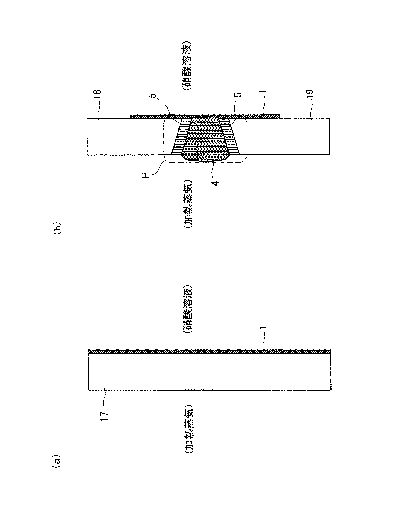
表1において、溶接材料No.A〜C、G、およびHは、本発明の化学組成を有する溶接材料1であり、溶接材料No.D〜F、およびI〜Lは、本発明の化学組成のうち少なくとも1つの化学組成条件を満たさない比較例としての溶接材料1である。なお、表1において下線を付したものが、本発明の条件を満たさない化学組成条件である。表1に示す溶接材料(No.A〜L)は、それぞれ、その鋼材150kgを真空誘導溶解(VIM)し、真空中で金型に鋳込み、鋳塊を得た後、当該鋳塊から電極を削りだし、電子ビーム再溶解(EB)を施して円柱鋳塊とし、さらに、鍛造および線引き加工により2.4mmφの溶加棒に加工したものである。
In Table 1, welding material No. A to C, G, and H are welding
原子炉内部配管を構成するオーステナイト系ステンレス鋼の一部は溶接を行うと溶接金属4の両側の熱影響部5に鋭敏化部を生じ、配管の供用中に粒界応力腐食割れを発生する場合がある。これを防止するため、配管内面の熱影響部5を覆うような肉盛溶接状態を模擬したのである。なお、配管の鋼材としては、SUS304鋼だけでなく、SUS316鋼、SUS316L鋼など他のオーステナイト系ステンレス鋼が使用される場合もある。また、本実施形態では、溶接金属4が市販のY308であるため、熱影響部5、溶接金属4およびその近傍を溶接材料1で肉盛溶接しているが、溶接金属4を、本発明の化学組成を有するオーステナイト系ステンレス鋼からなる溶接材料とした場合には、熱影響部5およびその近傍のみを本発明に係る溶接材料1で肉盛溶接するだけとしてもよい。
When a part of austenitic stainless steel constituting the reactor internal pipe is welded, a sensitized part is formed in the heat-affected
そして、溶接継手試験材11から機械加工により図1に点線で示したCBB(隙間腐食応力割れ)試験片6を採取した。CBB試験片6は、厚さ2mm×幅10mm×長さ50mmの試験片である。このCBB試験片6をオートクレーブ中で図2に示した治具にて、高温高圧中(飽和酸素濃度8ppm、70kgf/cm2、290℃)に500時間浸漬して実施した。CBB試験片6にすきまを付けるためのグラファイトファイバーウール7とともに当該CBB試験片6をホルダー8間にセットし、ホルダー8端部の孔4に挟み付けボルトを挿入し、ホルダー8間にアールを付けて締め付けた。なお、ホルダー8は、100Rに湾曲した箇所を有している。浸漬後、CBB試験片6を取出し、当該CBB試験片6の断面観察から割れ発生の有無を評価した。
And the CBB (crevice corrosion stress cracking)
また、表1に示した溶接材料(No.A〜L)に対して、高酸化性の金属イオンを含有する高濃度沸騰硝酸溶液中での粒界腐食状況を模擬してCoriou腐食試験を行った。この腐食試験はCr6+イオンを1.0g/L添加した500mlの8規定沸騰硝酸溶液を用い、液を更新しながら24時間を1バッチとする浸漬試験を4バッチ行い、腐食減量を測定して腐食速度等を評価した。 In addition, a Corio corrosion test was performed on the welding materials (Nos. A to L) shown in Table 1 by simulating the intergranular corrosion situation in a high concentration boiling nitric acid solution containing highly oxidizable metal ions. It was. In this corrosion test, 500 ml of 8N boiling nitric acid solution with 1.0 g / L of Cr6 + ions added was used, and four immersion tests were performed with 24 batches as one batch while renewing the solution. The speed etc. were evaluated.
表2に、CBB試験およびCoriou試験の結果を示す。なお、表2中のCBB試験結果において、「○」は最大割れ深さが15μm未満の場合であり、「×」は最大割れ深さが15μm以上の場合である。また、表2中の溶接材料のNo.「無」の行は、図1に示した溶接継手試験材11において、溶接材料1で肉盛溶接していない場合(比較例)の試験結果である。
Table 2 shows the results of the CBB test and the Corio test. In the CBB test results in Table 2, “◯” indicates that the maximum crack depth is less than 15 μm, and “x” indicates that the maximum crack depth is 15 μm or more. In Table 2, the welding material Nos. The row of “None” is the test result when the welded
表2の試験結果から、溶接部をなす配管の母材(本評価試験では、板材2,3)が高い炭素量を有するオーステナイト系ステンレス鋼である場合でも、化学組成が本発明の溶接材料1を用いて溶接継手の熱影響部5(溶接接合部P)を肉盛溶接することにより良好な耐応力腐食割れ性や耐粒界腐食性が得られることがわかる。
From the test results in Table 2, the chemical composition is the
すなわち、溶接材料(オーステナイト系ステンレス鋼溶接材料)に含まれる、C、Si、Mn、P、S、Ni、Cr、N、およびOの含有率を、本発明の化学組成とし、Bの含有率を3wtppm以下とし、かつ、C、P、S、NおよびOの含有率の合計を0.02wt%以下とすることにより、当該溶接材料の粒界腐食を抑え、応力腐食割れを十分に抑制することができる。したがって、この溶接材料を、原子力発電プラントなどにおける装置類、配管などの溶接材料として使用することで、溶接による熱影響部の応力腐食割れなどの発生や進展を効果的に防止することができる。 That is, the content of C, Si, Mn, P, S, Ni, Cr, N, and O contained in the welding material (austenitic stainless steel welding material) is the chemical composition of the present invention, and the content of B Is 3 wtppm or less, and the total content of C, P, S, N and O is 0.02 wt% or less, thereby suppressing intergranular corrosion of the welding material and sufficiently suppressing stress corrosion cracking. be able to. Therefore, by using this welding material as a welding material for equipment and piping in a nuclear power plant or the like, it is possible to effectively prevent the occurrence and progress of stress corrosion cracking or the like in the heat affected zone due to welding.
また、C、P、S、NおよびOの含有量の合計に対し化学量論的に等価以上の量のTiを添加することにより、粒界腐食の原因となるこれら不純物元素をTiC,FeTiP,TiS,TiN,およびTiO2のようなTi系の炭窒化物や化合物とすることができ、これら不純物元素を完全に無害化することができる。 Further, by adding Ti in a stoichiometrically equivalent amount or more with respect to the total content of C, P, S, N, and O, these impurity elements that cause intergranular corrosion are changed to TiC, FeTiP, Ti-based carbonitrides and compounds such as TiS, TiN, and TiO 2 can be used, and these impurity elements can be completely detoxified.
また、図1には、原子炉プラントに用いられるSUS304鋼製(オーステナイト系ステンレス鋼製)の配管の溶接に際し、原子炉水と接する側の溶接接合部Pに、本発明の溶接材料1を肉盛溶接する応力腐食割れ予防保全方法を模擬して示している。本応力腐食割れ予防保全方法によると、原子炉プラントに用いられる配管の溶接接合部Pにおける応力腐食割れなどの発生や進展を効果的に防止することができる。
Further, in FIG. 1, when welding a pipe made of SUS304 steel (made of austenitic stainless steel) used in a nuclear reactor plant, the
なお、本発明の応力腐食割れ予防保全方法は、化学プラントなどに用いられるSUS304鋼などのオーステナイト系ステンレス鋼製の配管溶接に際し適用してもよいし、配管の溶接だけでなく構造物などの溶接に適用することもできる。また、原子炉水と接する側(炉水側)の溶接接合部Pだけでなく、その反対側の溶接接合部Pに本発明の溶接材料1を肉盛溶接してもよい。
Note that the stress corrosion cracking preventive maintenance method of the present invention may be applied to pipe welding made of austenitic stainless steel such as SUS304 steel used in a chemical plant or the like, and not only pipe welding but also structure welding. It can also be applied to. Moreover, you may build-up the
(応力腐食割れ予防保全方法の他の実施態様)
次に、応力腐食割れ予防保全方法の他の実施態様について説明する。図3は、本発明に係る溶接材料1で肉盛溶接した配管21,31を示す断面図である。
(Another embodiment of the stress corrosion cracking preventive maintenance method)
Next, another embodiment of the stress corrosion cracking preventive maintenance method will be described. FIG. 3 is a cross-sectional view showing the
図3(a)は、SUS304鋼管材(管材13,14)などのオーステナイト系ステンレス鋼管が溶接接合された後、原子炉内において原子炉水に曝されて粒界腐食または粒界応力腐食割れなどの欠陥が発見された場合に、その欠陥部を除去し、本発明の化学組成を有する溶接材料1で肉盛溶接した状況を示す図である。
FIG. 3 (a) shows an example of intergranular corrosion or intergranular stress corrosion cracking after austenitic stainless steel pipes such as SUS304 steel pipes (
本実施形態の応力腐食割れ予防保全方法では、溶接接合部Pの欠陥部を除去して補修溶接し(補修部10)、その後、溶接接合部Pである熱影響部5、溶接金属4、補修部10、および新たな熱影響部12を覆うように、本発明の化学組成を有する溶接材料1で肉盛溶接する。これにより、補修溶接部(補修部10)、および補修溶接によって生じた熱影響部12における応力腐食割れなどの発生や進展を効果的に防止することができる。なお、補修部10の溶接材料として、本発明の化学組成を有する溶接材料1を用いてもよい。これにより、新たな熱影響部12の発生を防止することができるとともに、補修部10自体の耐粒界腐食性や耐応力腐食割れ性が向上する。また、本実施形態の溶接金属4はY308であるが、Y308の代わりに本発明の化学組成を有する溶接材料1を用いて、管材13と管材14とを突合せ溶接してもよい。
In the stress corrosion cracking preventive maintenance method of the present embodiment, the defective portion of the weld joint P is removed and repair welded (the repair portion 10), and then the heat affected
次に、図3(b)は、図3(a)に示した管材13(オーステナイト系ステンレス鋼管)が原子炉内において原子炉水に曝されて、当該管材13に粒界腐食または粒界応力腐食割れなどの欠陥が発見された場合に、当該管材13を対策材15に取り替えた状況を示す図である。
Next, FIG. 3B shows that the pipe material 13 (austenitic stainless steel pipe) shown in FIG. 3A is exposed to reactor water in the nuclear reactor, and the
本実施形態の応力腐食割れ予防保全方法では、まず、管材13と管材14とを分離する。そして、欠陥が発見された管材13の替わりに対策材15(管材)を用意し、当該対策材15の開先面15aおよびその近傍の管面15b、15cに、本発明の化学組成を有する溶接材料1を肉盛溶接する。同様に、管材14の開先面14aおよびその近傍の管面14b、14cにも本発明の溶接材料1を肉盛溶接する。その後、対策材15と管材14とを突合せ溶接する。ここで、管面15bおよび管面14bは、それぞれ、対策材15および管材14の炉水側の面であり、管面15cおよび管面14cは、それぞれ、対策材15および管材14の炉水側とは反対側の面である。また、本発明の溶接材料1による管の内外面に対する肉盛溶接面積は、炉水側のほうが大きい。
In the stress corrosion cracking preventive maintenance method of the present embodiment, first, the
溶接材料1を予め開先面に肉盛溶接しておくことにより、熱影響相当部の鋭敏化が抑えられ、応力腐食割れなどの発生や進展を効果的に防止することができる。なお、対策材15の鋼材としては、SUS304、SUS316、SUS316Lなどのオーステナイト系ステンレス鋼が挙げられる。また、溶接金属16としては、対策材15と管材14とを溶接するのに適した市販の(従来の)溶接金属でもよいし、本発明の化学組成を有する溶接材料1を用いてもよい。本発明の溶接材料1を用いると、溶接金属16部自体の耐粒界腐食性や耐応力腐食割れ性が向上する。
By overlay welding the
(粒界腐食予防保全方法)
次に、本発明の化学組成を有する溶接材料1を用いた粒界腐食予防保全方法について説明する。図4は、本発明に係る粒界腐食予防保全方法について説明するための図である。
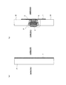
(Prevention and maintenance of intergranular corrosion)
Next, the intergranular corrosion preventive maintenance method using the
図4(a)は、SUS304鋼製の構造物17の腐食性流体が接触する接液面に対して、本発明の化学組成を有する溶接材料1を肉盛溶接した状況を示す図である。
FIG. 4 (a) is a diagram showing a situation in which the
上記構造物17は、使用済み核燃料の再処理プラントにおいて、高酸化性の金属イオンを含有する高濃度硝酸溶液の沸騰伝熱面腐食環境で使用されるオーステナイト系ステンレス鋼製構造物である。なお、構造物17に対して本発明の溶接材料1を肉盛溶接する形態ではなく、配管に対して本発明の溶接材料1を肉盛溶接する形態であってもよい(図4(b)に示した実施形態においても同様)。
The
本実施形態では、構造物17の硝酸溶液接液側の全面に、本発明の溶接材料1を肉盛溶接している。これにより、構造物17に対して硝酸溶液が直接接触しないようにすることができるので、構造物17の粒界腐食を効果的に防止することができる。
In this embodiment, the
次に、図4(b)は、SUS304鋼製の構造物18の腐食性流体が接触する接液側の溶接接合部Pに、本発明の化学組成を有する溶接材料1を肉盛溶接した状況を示す図である。
Next, FIG.4 (b) is the situation where the
図4(b)に示したように、本発明の溶接材料1で、溶接金属4、熱影響部5およびその近傍を覆うように、構造物18の硝酸溶液が接触する接液側の溶接接合部Pを肉盛溶接している。なお、構造物18は、構造物17と同様に、使用済み核燃料の再処理プラントにおいて、高酸化性の金属イオンを含有する高濃度硝酸溶液の沸騰伝熱面腐食環境で使用されるオーステナイト系ステンレス鋼製構造物である。
As shown in FIG. 4B, the
本実施形態によると、構造物18の溶接接合部Pに対して、硝酸溶液が直接接触しないようにすることができるので、当該溶接接合部Pの粒界腐食を効果的に防止することができる。
According to the present embodiment, it is possible to prevent the nitric acid solution from coming into direct contact with the weld joint P of the
なお、図1、図3〜4において、本発明の溶接材料1による肉盛溶接部の母材には、熱影響部の表示をしていない。これは、前記したように、本発明の化学組成を有する溶接材料1においては、その高純度化により液相−固相共存温度域が狭くなるため、肉盛溶接部端縁部への熱拡散が小さい。そのため、母材の温度上昇を小さく抑えることができ、結果として、熱影響部すなわち鋭敏化領域が狭くなるからである。
In FIGS. 1 and 3 to 4, the heat affected zone is not displayed on the base material of the overlay welded portion of the
以上、本発明の実施形態について説明したが、本発明は上述の実施の形態に限られるものではなく、特許請求の範囲に記載した限りにおいて様々に変更して実施することが可能なものである。 Although the embodiments of the present invention have been described above, the present invention is not limited to the above-described embodiments, and various modifications can be made as long as they are described in the claims. .
1:溶接材料
13、14:SUS304鋼製管材
15:対策材
P:溶接接合部
1:
Claims (7)
前記オーステナイト系ステンレス鋼に含まれるBの含有率が3wtppm以下であり、かつ、前記C、P、S、NおよびOの含有率の合計が0.02wt%以下であることを特徴とする、溶接材料。 C: 0.01 wt% or less, Si: 0.5 wt% or less, Mn: 0.5 wt% or less, P: 0.005 wt% or less, S: 0.005 wt% or less, Ni: 15.0 to 40.0 wt% Cr: 20.0-30.0 wt%, N: 0.01 wt% or less, O: a welding material made of austenitic stainless steel containing 0.01 wt% or less,
The content of B contained in the austenitic stainless steel is 3 wtppm or less, and the total content of C, P, S, N and O is 0.02 wt% or less. material.
前記オーステナイト系ステンレス鋼に含まれるTiの含有量が、前記C、P、S、NおよびOの含有量の合計に対し、化学量論的に等価以上であることを特徴とする、溶接材料。 The welding material according to claim 1,
A welding material, wherein the content of Ti contained in the austenitic stainless steel is stoichiometrically equivalent to or greater than the total content of C, P, S, N and O.
前記溶接接合部の欠陥部を除去して補修溶接し、その後、当該溶接接合部を覆うように前記溶接材料で肉盛溶接することを特徴とする、応力腐食割れ予防保全方法。 In the stress corrosion cracking preventive maintenance method according to claim 3,
A stress corrosion cracking preventive maintenance method characterized by removing and repairing a defective portion of the welded joint, and then overlay welding with the welding material so as to cover the welded joint.
Priority Applications (7)
| Application Number | Priority Date | Filing Date | Title |
|---|---|---|---|
| JP2008322639A JP5463527B2 (en) | 2008-12-18 | 2008-12-18 | Welding material made of austenitic stainless steel, stress corrosion cracking preventive maintenance method and intergranular corrosion preventive maintenance method using the same |
| RU2011129636/02A RU2488471C2 (en) | 2008-12-18 | 2009-12-16 | Austenite welding material and method of preventive servicing to rule out corrosion cracking at stress, and method of preventing servicing to rule out intercrystalline corrosion |
| EP09833449.3A EP2422919B1 (en) | 2008-12-18 | 2009-12-16 | Austenitic welding material, and preventive maintenance method for stress corrosion cracking and preventive maintenance method for intergranular corrosion, using same |
| KR1020117016457A KR101305778B1 (en) | 2008-12-18 | 2009-12-16 | Austenite-based weld material, and preventive maintenance method for stress corrosion cracking and preventive maintenance method for grain boundary corrosion using same |
| CN200980150398.4A CN102245345B (en) | 2008-12-18 | 2009-12-16 | Austenite-based weld and employ stress corrosion cracking preventive maintenance method and the grain boundary corrosion preventive maintenance method of this material |
| US13/140,674 US8322592B2 (en) | 2008-12-18 | 2009-12-16 | Austenitic welding material, and preventive maintenance method for stress corrosion cracking and preventive maintenance method for intergranular corrosion, using same |
| PCT/JP2009/070965 WO2010071146A1 (en) | 2008-12-18 | 2009-12-16 | Austenite-based weld material, and preventive maintenance method for stress corrosion cracking and preventive maintenance method for grain boundary corrosion using same |
Applications Claiming Priority (1)
| Application Number | Priority Date | Filing Date | Title |
|---|---|---|---|
| JP2008322639A JP5463527B2 (en) | 2008-12-18 | 2008-12-18 | Welding material made of austenitic stainless steel, stress corrosion cracking preventive maintenance method and intergranular corrosion preventive maintenance method using the same |
Publications (2)
| Publication Number | Publication Date |
|---|---|
| JP2010142843A true JP2010142843A (en) | 2010-07-01 |
| JP5463527B2 JP5463527B2 (en) | 2014-04-09 |
Family
ID=42268817
Family Applications (1)
| Application Number | Title | Priority Date | Filing Date |
|---|---|---|---|
| JP2008322639A Active JP5463527B2 (en) | 2008-12-18 | 2008-12-18 | Welding material made of austenitic stainless steel, stress corrosion cracking preventive maintenance method and intergranular corrosion preventive maintenance method using the same |
Country Status (7)
| Country | Link |
|---|---|
| US (1) | US8322592B2 (en) |
| EP (1) | EP2422919B1 (en) |
| JP (1) | JP5463527B2 (en) |
| KR (1) | KR101305778B1 (en) |
| CN (1) | CN102245345B (en) |
| RU (1) | RU2488471C2 (en) |
| WO (1) | WO2010071146A1 (en) |
Cited By (2)
| Publication number | Priority date | Publication date | Assignee | Title |
|---|---|---|---|---|
| KR20130137248A (en) * | 2011-05-13 | 2013-12-16 | 신닛테츠스미킨 카부시키카이샤 | Welding material and welded joint |
| JP2015055570A (en) * | 2013-09-12 | 2015-03-23 | 三菱重工業株式会社 | Material selection method and device for thermal spray film or build-up welding layer |
Families Citing this family (10)
| Publication number | Priority date | Publication date | Assignee | Title |
|---|---|---|---|---|
| DK2492042T3 (en) * | 2009-12-04 | 2015-08-10 | Nippon Steel & Sumitomo Metal Corp | Welded structure with a stuk welded assembly and manufacturing method thereof |
| WO2015129631A1 (en) * | 2014-02-26 | 2015-09-03 | 新日鐵住金株式会社 | Welded joint |
| WO2016016717A1 (en) * | 2014-07-31 | 2016-02-04 | Sabic Global Technologies B.V. | Repair of sigmatized stainless steels |
| WO2017142435A1 (en) * | 2016-02-19 | 2017-08-24 | Общество С Ограниченной Ответственностью "Ромет" | Method of welding an article made of corrosion resistant multi-layered metal materials |
| US10493569B2 (en) * | 2016-05-02 | 2019-12-03 | Exxonmobil Research And Engineering Company | Field girth welding technology for high manganese steel slurry pipelines |
| US9541485B1 (en) * | 2016-08-15 | 2017-01-10 | Kuwait Institute For Scientific Research | System for testing stress corrosion cracking |
| EP3574179B1 (en) | 2017-01-30 | 2023-09-27 | National Oilwell Varco, L.P. | Enhanced welded pipe, threaded connections, and methods for achieving the same |
| US10625361B2 (en) * | 2017-06-14 | 2020-04-21 | General Electric Company | Method of welding superalloys |
| JP7082541B2 (en) * | 2018-07-20 | 2022-06-08 | 三菱重工業株式会社 | Repair welding method |
| KR20200101647A (en) | 2019-02-20 | 2020-08-28 | 한양대학교 산학협력단 | Supper austenitic stainless steel |
Citations (4)
| Publication number | Priority date | Publication date | Assignee | Title |
|---|---|---|---|---|
| JP2000254776A (en) * | 1999-03-10 | 2000-09-19 | Toshiba Corp | Stress corrosion crack prevention method for atomic reactor-inside piping welded part |
| JP2001124888A (en) * | 1999-10-26 | 2001-05-11 | Toshiba Corp | Maintenance method for preventing stress corrosion cracking |
| JP2006183082A (en) * | 2004-12-27 | 2006-07-13 | Sumitomo Metal Ind Ltd | WELD JOINT OF HIGH-Cr STEEL AND WELDING MATERIAL THEREFOR |
| WO2008136354A1 (en) * | 2007-04-27 | 2008-11-13 | Japan Atomic Energy Agency | Austenitic stainless steel excellent in intergranular corrosion resistance and stress corrosion cracking resistance, and method for producing austenitic stainless steel |
Family Cites Families (48)
| Publication number | Priority date | Publication date | Assignee | Title |
|---|---|---|---|---|
| US3017266A (en) * | 1960-06-02 | 1962-01-16 | United Steel Companies Ltd | Austenitic steel and articles made therefrom |
| US3151978A (en) * | 1960-12-30 | 1964-10-06 | Armco Steel Corp | Heat hardenable chromium-nickel-aluminum steel |
| US3306736A (en) * | 1963-08-30 | 1967-02-28 | Crucible Steel Co America | Austenitic stainless steel |
| AT268345B (en) * | 1965-03-09 | 1969-02-10 | Schoeller Bleckmann Stahlwerke | Austenitic, corrosion-resistant chromium-nickel-manganese-nitrogen steel for the production of objects that are resistant to pitting and stress corrosion cracking in seawater and have non-magnetizability and good weldability |
| DE1558635B2 (en) * | 1966-02-10 | 1970-06-18 | Sumitomo Kinzoku Kogyo Kabushiki Kaisha, Osaka (Japan) | High-strength, stable austenitic corrosion-resistant steel for the production of evaporator tubes and superheater tubes |
| AT295954B (en) * | 1969-07-11 | 1972-01-25 | Boehler & Co Ag Geb | Welding material for electric arc welding of objects made of cold-tough steel |
| SU427815A1 (en) * | 1973-01-02 | 1974-05-15 | Ю. М. Белов , В. А. Красавчиков | FILLING MATERIAL |
| US4049186A (en) * | 1976-10-20 | 1977-09-20 | General Electric Company | Process for reducing stress corrosion in a weld by applying an overlay weld |
| JPS5431062A (en) * | 1977-08-12 | 1979-03-07 | Hitachi Ltd | Manufacture of structure superior in stress corrosion cracking resistivity |
| JPS5921711B2 (en) | 1978-07-11 | 1984-05-22 | 株式会社日立製作所 | How to weld stainless steel materials |
| JPS56131083A (en) * | 1980-11-10 | 1981-10-14 | Hitachi Ltd | Welded joint method for stainless steel tube |
| DE3225266A1 (en) | 1982-07-06 | 1984-01-12 | Bayer Ag, 5090 Leverkusen | CONTINUOUS DRY SPINNING PROCESS FOR ACRYLNITRILE THREADS AND FIBERS |
| US4624402A (en) * | 1983-01-18 | 1986-11-25 | Nutech, Inc. | Method for applying an overlay weld for preventing and controlling stress corrosion cracking |
| JPS60100629A (en) * | 1983-11-08 | 1985-06-04 | Sumitomo Metal Ind Ltd | Production of austenite stainless steel |
| JPS60152661A (en) * | 1984-01-23 | 1985-08-10 | Daido Steel Co Ltd | Free-cutting austenitic stainless steel |
| JPS61177325A (en) | 1985-01-31 | 1986-08-09 | Sumitomo Metal Ind Ltd | Improvement of corrosion resistance or stainles steel weld zone |
| JPH0647708B2 (en) * | 1985-07-31 | 1994-06-22 | 大同特殊鋼株式会社 | Austenitic free-cutting stainless steel |
| JPS6369947A (en) | 1986-09-11 | 1988-03-30 | Kawasaki Steel Corp | Austenitic stainless steel having superior creep rupture ductility |
| SE8904065L (en) * | 1988-12-07 | 1990-06-08 | Hitachi Ltd | METHOD OF IMPROVING THE PROPERTIES OF AUSTENITIC STAINLESS STEEL WELDERS |
| JP2865749B2 (en) | 1988-12-07 | 1999-03-08 | 株式会社日立製作所 | Piping reforming method |
| JP2831051B2 (en) * | 1989-09-22 | 1998-12-02 | 株式会社神戸製鋼所 | Austenitic stainless steel welding wire |
| US4962586A (en) * | 1989-11-29 | 1990-10-16 | Westinghouse Electric Corp. | Method of making a high temperature - low temperature rotor for turbines |
| JP2530231B2 (en) * | 1989-12-20 | 1996-09-04 | 日新製鋼株式会社 | Heat-resistant austenitic stainless steel |
| JPH0577082A (en) | 1991-09-20 | 1993-03-30 | Hitachi Ltd | Method for reforming welded part in austenitic stainless steel |
| KR100259557B1 (en) * | 1993-10-20 | 2000-06-15 | 고지마 마타오 | Stainless steel for high purity gas |
| JPH085773A (en) | 1994-06-20 | 1996-01-12 | Toshiba Corp | Preventive maintenance device and method for jet pump |
| JPH0929429A (en) * | 1995-07-21 | 1997-02-04 | Toshiba Corp | Welding procedure |
| US5809098A (en) * | 1997-03-10 | 1998-09-15 | General Electric Company | Method for sealing a stub tube in a nuclear reactor |
| JP2000312969A (en) | 1999-04-30 | 2000-11-14 | Ishikawajima Harima Heavy Ind Co Ltd | Outer face buttering process of welding joint |
| JP2001107196A (en) * | 1999-10-07 | 2001-04-17 | Sumitomo Metal Ind Ltd | Austenitic steel welded joint excellent in weld cracking resistance and sulfuric acid corrosion resistance and the welding material |
| JP4465066B2 (en) * | 1999-10-18 | 2010-05-19 | 日本冶金工業株式会社 | Welding materials for ferrite and austenitic duplex stainless steels |
| JP2001138048A (en) | 1999-11-08 | 2001-05-22 | Kobe Steel Ltd | Method of executing for build-up welding for molybdenum-containing austenite-based stainless steel |
| KR100482208B1 (en) * | 2000-11-17 | 2005-04-21 | 주식회사 포스코 | Method for manufacturing steel plate having superior toughness in weld heat-affected zone by nitriding treatment |
| JP4490608B2 (en) * | 2001-08-09 | 2010-06-30 | 株式会社東芝 | Repair method of structure |
| KR100532877B1 (en) * | 2002-04-17 | 2005-12-01 | 스미토모 긴조쿠 고교 가부시키가이샤 | Austenitic stainless steel excellent in high temperature strength and corrosion resistance, heat resistant pressurized parts, and the manufacturing method thereof |
| JP4424471B2 (en) * | 2003-01-29 | 2010-03-03 | 住友金属工業株式会社 | Austenitic stainless steel and method for producing the same |
| JP4188124B2 (en) * | 2003-03-31 | 2008-11-26 | 独立行政法人物質・材料研究機構 | Welded joints of tempered martensitic heat-resistant steel |
| JP3838216B2 (en) * | 2003-04-25 | 2006-10-25 | 住友金属工業株式会社 | Austenitic stainless steel |
| EP1683885B1 (en) * | 2003-10-31 | 2013-05-29 | JFE Steel Corporation | High strength stainless steel pipe for line pipe excellent in corrosion resistance and method for production thereof |
| US6969826B2 (en) * | 2004-04-08 | 2005-11-29 | General Electric Company | Welding process |
| US7533795B2 (en) * | 2004-12-22 | 2009-05-19 | General Electric Company | Welding process |
| KR20070107140A (en) * | 2005-03-25 | 2007-11-06 | 수미도모 메탈 인더스트리즈, 리미티드 | Hollow driving shaft obtained through inducti0n hardening |
| CN100577844C (en) * | 2005-04-04 | 2010-01-06 | 住友金属工业株式会社 | Austenitic stainless steel |
| US8710405B2 (en) * | 2005-04-15 | 2014-04-29 | Nippon Steel & Sumikin Stainless Steel Corporation | Austenitic stainless steel welding wire and welding structure |
| EP1876253B1 (en) * | 2005-04-28 | 2013-04-17 | JFE Steel Corporation | Stainless steel pipe for oil well excellent in enlarging characteristics |
| US20080240970A1 (en) * | 2007-03-31 | 2008-10-02 | Daido Tokushuko Kabushiki Kaisha | Austenitic free-cutting stainless steel |
| KR20090066000A (en) * | 2007-12-18 | 2009-06-23 | 주식회사 포스코 | Austenitic stainless steel for the high vacuum or high purity gas tube application |
| US8319148B2 (en) * | 2009-08-20 | 2012-11-27 | General Electric Company | System and method of dual laser beam welding of first and second filler metals |
-
2008
- 2008-12-18 JP JP2008322639A patent/JP5463527B2/en active Active
-
2009
- 2009-12-16 CN CN200980150398.4A patent/CN102245345B/en active Active
- 2009-12-16 EP EP09833449.3A patent/EP2422919B1/en active Active
- 2009-12-16 WO PCT/JP2009/070965 patent/WO2010071146A1/en active Application Filing
- 2009-12-16 RU RU2011129636/02A patent/RU2488471C2/en active
- 2009-12-16 US US13/140,674 patent/US8322592B2/en active Active
- 2009-12-16 KR KR1020117016457A patent/KR101305778B1/en active IP Right Grant
Patent Citations (4)
| Publication number | Priority date | Publication date | Assignee | Title |
|---|---|---|---|---|
| JP2000254776A (en) * | 1999-03-10 | 2000-09-19 | Toshiba Corp | Stress corrosion crack prevention method for atomic reactor-inside piping welded part |
| JP2001124888A (en) * | 1999-10-26 | 2001-05-11 | Toshiba Corp | Maintenance method for preventing stress corrosion cracking |
| JP2006183082A (en) * | 2004-12-27 | 2006-07-13 | Sumitomo Metal Ind Ltd | WELD JOINT OF HIGH-Cr STEEL AND WELDING MATERIAL THEREFOR |
| WO2008136354A1 (en) * | 2007-04-27 | 2008-11-13 | Japan Atomic Energy Agency | Austenitic stainless steel excellent in intergranular corrosion resistance and stress corrosion cracking resistance, and method for producing austenitic stainless steel |
Non-Patent Citations (1)
| Title |
|---|
| JPN6013018506; 才田一幸、他3名: '高純度化によるSUS310系ステンレス鋼の高温割れ感受性の変化原因-超高純度・高耐食合金の溶接性に関' 溶接学会全国大会講演概要 No.81, 20070901, Page.100-101 * |
Cited By (4)
| Publication number | Priority date | Publication date | Assignee | Title |
|---|---|---|---|---|
| KR20130137248A (en) * | 2011-05-13 | 2013-12-16 | 신닛테츠스미킨 카부시키카이샤 | Welding material and welded joint |
| KR101597010B1 (en) | 2011-05-13 | 2016-02-23 | 신닛테츠스미킨 카부시키카이샤 | Welding material and welded joint |
| US10201880B2 (en) | 2011-05-13 | 2019-02-12 | Nippon Steel & Sumitomo Metal Corporation | Welding material and welding joint |
| JP2015055570A (en) * | 2013-09-12 | 2015-03-23 | 三菱重工業株式会社 | Material selection method and device for thermal spray film or build-up welding layer |
Also Published As
| Publication number | Publication date |
|---|---|
| RU2488471C2 (en) | 2013-07-27 |
| WO2010071146A1 (en) | 2010-06-24 |
| EP2422919A1 (en) | 2012-02-29 |
| EP2422919B1 (en) | 2019-02-20 |
| KR20110098822A (en) | 2011-09-01 |
| US8322592B2 (en) | 2012-12-04 |
| RU2011129636A (en) | 2013-01-27 |
| CN102245345B (en) | 2015-09-02 |
| JP5463527B2 (en) | 2014-04-09 |
| CN102245345A (en) | 2011-11-16 |
| EP2422919A4 (en) | 2013-06-19 |
| KR101305778B1 (en) | 2013-09-06 |
| US20110248071A1 (en) | 2011-10-13 |
Similar Documents
| Publication | Publication Date | Title |
|---|---|---|
| JP5463527B2 (en) | Welding material made of austenitic stainless steel, stress corrosion cracking preventive maintenance method and intergranular corrosion preventive maintenance method using the same | |
| US20220259688A1 (en) | Austenitic stainless steel material and welded joint | |
| JP2005336601A (en) | Martensitic stainless steel tube | |
| RU2595305C1 (en) | Welding wire for welding different steels | |
| JP2003311321A (en) | Method for manufacturing high-strength uoe steel tube | |
| Kain et al. | Controlling corrosion in the back end of fuel cycle using nitric acid grade stainless steels | |
| JP4196755B2 (en) | Pipe welded joint of low carbon stainless steel pipe and its manufacturing method | |
| JP4273339B2 (en) | High Cr steel welded joints and welding materials | |
| JP4026554B2 (en) | Pipe welded joint of low carbon stainless steel pipe and its manufacturing method | |
| JP2000254776A (en) | Stress corrosion crack prevention method for atomic reactor-inside piping welded part | |
| JP2865749B2 (en) | Piping reforming method | |
| JP2011068967A (en) | Water storage tank constructed by welding panel made from stainless steel | |
| Kelly | Stainless steels | |
| JP2006161114A (en) | Austenitic stainless steel material and weld joint thereof | |
| JP7140207B2 (en) | METHOD FOR MANUFACTURING FERRITIC HEAT-RESISTANT STEEL WELD JOINT | |
| JP4513515B2 (en) | Welded joint with excellent corrosion resistance | |
| JP2000288738A (en) | Structure in welded joint of high chrominum ferrite steel | |
| JP2006159262A (en) | Welded joint and welding material | |
| Lauro et al. | Welding and weldability of the ‘super-austenitic’and ‘super-martensitic’stainless steels | |
| Iwamoto et al. | Japanese Welding Guideline for Duplex Stainless Steels | |
| JP4412533B2 (en) | Method for improving and repairing stress corrosion cracking of high nickel alloy | |
| CN117620514A (en) | High corrosion resistant gas shielded welding wire capable of bearing 10-30kJ/cm heat input | |
| JP2001141878A (en) | Method for preventing corrosion of shielding structure against thermal neutrons | |
| JP2021178995A (en) | Stainless steel pipe and weld joint | |
| JP2022114890A (en) | Ferrite-austenite duplex stainless steel welded structures, ferrite-austenite duplex stainless steel welded joints, and methods of welding ferrite-austenite duplex stainless steel materials |
Legal Events
| Date | Code | Title | Description |
|---|---|---|---|
| A621 | Written request for application examination |
Free format text: JAPANESE INTERMEDIATE CODE: A621 Effective date: 20110801 |
|
| A521 | Request for written amendment filed |
Free format text: JAPANESE INTERMEDIATE CODE: A821 Effective date: 20110801 |
|
| A131 | Notification of reasons for refusal |
Free format text: JAPANESE INTERMEDIATE CODE: A131 Effective date: 20130611 |
|
| A521 | Request for written amendment filed |
Free format text: JAPANESE INTERMEDIATE CODE: A523 Effective date: 20130731 |
|
| A131 | Notification of reasons for refusal |
Free format text: JAPANESE INTERMEDIATE CODE: A131 Effective date: 20130917 |
|
| A521 | Request for written amendment filed |
Free format text: JAPANESE INTERMEDIATE CODE: A523 Effective date: 20131018 |
|
| TRDD | Decision of grant or rejection written | ||
| A01 | Written decision to grant a patent or to grant a registration (utility model) |
Free format text: JAPANESE INTERMEDIATE CODE: A01 Effective date: 20131210 |
|
| A61 | First payment of annual fees (during grant procedure) |
Free format text: JAPANESE INTERMEDIATE CODE: A61 Effective date: 20131224 |
|
| R150 | Certificate of patent or registration of utility model |
Free format text: JAPANESE INTERMEDIATE CODE: R150 Ref document number: 5463527 Country of ref document: JP Free format text: JAPANESE INTERMEDIATE CODE: R150 |
|
| S531 | Written request for registration of change of domicile |
Free format text: JAPANESE INTERMEDIATE CODE: R313531 |
|
| S533 | Written request for registration of change of name |
Free format text: JAPANESE INTERMEDIATE CODE: R313533 |
|
| R350 | Written notification of registration of transfer |
Free format text: JAPANESE INTERMEDIATE CODE: R350 |
|
| S111 | Request for change of ownership or part of ownership |
Free format text: JAPANESE INTERMEDIATE CODE: R313117 |
|
| R350 | Written notification of registration of transfer |
Free format text: JAPANESE INTERMEDIATE CODE: R350 |
|
| R250 | Receipt of annual fees |
Free format text: JAPANESE INTERMEDIATE CODE: R250 |
|
| R250 | Receipt of annual fees |
Free format text: JAPANESE INTERMEDIATE CODE: R250 |
|
| R250 | Receipt of annual fees |
Free format text: JAPANESE INTERMEDIATE CODE: R250 |
|
| R250 | Receipt of annual fees |
Free format text: JAPANESE INTERMEDIATE CODE: R250 |
|
| R250 | Receipt of annual fees |
Free format text: JAPANESE INTERMEDIATE CODE: R250 |
|
| R250 | Receipt of annual fees |
Free format text: JAPANESE INTERMEDIATE CODE: R250 |
|
| R250 | Receipt of annual fees |
Free format text: JAPANESE INTERMEDIATE CODE: R250 |
|
| R250 | Receipt of annual fees |
Free format text: JAPANESE INTERMEDIATE CODE: R250 |