JP2010129583A - Lighting fixture - Google Patents
Lighting fixture Download PDFInfo
- Publication number
- JP2010129583A JP2010129583A JP2008299591A JP2008299591A JP2010129583A JP 2010129583 A JP2010129583 A JP 2010129583A JP 2008299591 A JP2008299591 A JP 2008299591A JP 2008299591 A JP2008299591 A JP 2008299591A JP 2010129583 A JP2010129583 A JP 2010129583A
- Authority
- JP
- Japan
- Prior art keywords
- light
- color temperature
- white light
- phosphor
- correlated color
- Prior art date
- Legal status (The legal status is an assumption and is not a legal conclusion. Google has not performed a legal analysis and makes no representation as to the accuracy of the status listed.)
- Pending
Links
Images

Classifications
-
- F—MECHANICAL ENGINEERING; LIGHTING; HEATING; WEAPONS; BLASTING
- F21—LIGHTING
- F21K—NON-ELECTRIC LIGHT SOURCES USING LUMINESCENCE; LIGHT SOURCES USING ELECTROCHEMILUMINESCENCE; LIGHT SOURCES USING CHARGES OF COMBUSTIBLE MATERIAL; LIGHT SOURCES USING SEMICONDUCTOR DEVICES AS LIGHT-GENERATING ELEMENTS; LIGHT SOURCES NOT OTHERWISE PROVIDED FOR
- F21K9/00—Light sources using semiconductor devices as light-generating elements, e.g. using light-emitting diodes [LED] or lasers
-
- H—ELECTRICITY
- H05—ELECTRIC TECHNIQUES NOT OTHERWISE PROVIDED FOR
- H05B—ELECTRIC HEATING; ELECTRIC LIGHT SOURCES NOT OTHERWISE PROVIDED FOR; CIRCUIT ARRANGEMENTS FOR ELECTRIC LIGHT SOURCES, IN GENERAL
- H05B45/00—Circuit arrangements for operating light-emitting diodes [LED]
- H05B45/40—Details of LED load circuits
-
- F—MECHANICAL ENGINEERING; LIGHTING; HEATING; WEAPONS; BLASTING
- F21—LIGHTING
- F21Y—INDEXING SCHEME ASSOCIATED WITH SUBCLASSES F21K, F21L, F21S and F21V, RELATING TO THE FORM OR THE KIND OF THE LIGHT SOURCES OR OF THE COLOUR OF THE LIGHT EMITTED
- F21Y2113/00—Combination of light sources
- F21Y2113/10—Combination of light sources of different colours
- F21Y2113/13—Combination of light sources of different colours comprising an assembly of point-like light sources
-
- F—MECHANICAL ENGINEERING; LIGHTING; HEATING; WEAPONS; BLASTING
- F21—LIGHTING
- F21Y—INDEXING SCHEME ASSOCIATED WITH SUBCLASSES F21K, F21L, F21S and F21V, RELATING TO THE FORM OR THE KIND OF THE LIGHT SOURCES OR OF THE COLOUR OF THE LIGHT EMITTED
- F21Y2115/00—Light-generating elements of semiconductor light sources
- F21Y2115/10—Light-emitting diodes [LED]
-
- H—ELECTRICITY
- H01—ELECTRIC ELEMENTS
- H01L—SEMICONDUCTOR DEVICES NOT COVERED BY CLASS H10
- H01L2224/00—Indexing scheme for arrangements for connecting or disconnecting semiconductor or solid-state bodies and methods related thereto as covered by H01L24/00
- H01L2224/01—Means for bonding being attached to, or being formed on, the surface to be connected, e.g. chip-to-package, die-attach, "first-level" interconnects; Manufacturing methods related thereto
- H01L2224/42—Wire connectors; Manufacturing methods related thereto
- H01L2224/44—Structure, shape, material or disposition of the wire connectors prior to the connecting process
- H01L2224/45—Structure, shape, material or disposition of the wire connectors prior to the connecting process of an individual wire connector
- H01L2224/45001—Core members of the connector
- H01L2224/45099—Material
- H01L2224/451—Material with a principal constituent of the material being a metal or a metalloid, e.g. boron (B), silicon (Si), germanium (Ge), arsenic (As), antimony (Sb), tellurium (Te) and polonium (Po), and alloys thereof
- H01L2224/45138—Material with a principal constituent of the material being a metal or a metalloid, e.g. boron (B), silicon (Si), germanium (Ge), arsenic (As), antimony (Sb), tellurium (Te) and polonium (Po), and alloys thereof the principal constituent melting at a temperature of greater than or equal to 950°C and less than 1550°C
- H01L2224/45144—Gold (Au) as principal constituent
-
- H—ELECTRICITY
- H01—ELECTRIC ELEMENTS
- H01L—SEMICONDUCTOR DEVICES NOT COVERED BY CLASS H10
- H01L2224/00—Indexing scheme for arrangements for connecting or disconnecting semiconductor or solid-state bodies and methods related thereto as covered by H01L24/00
- H01L2224/01—Means for bonding being attached to, or being formed on, the surface to be connected, e.g. chip-to-package, die-attach, "first-level" interconnects; Manufacturing methods related thereto
- H01L2224/42—Wire connectors; Manufacturing methods related thereto
- H01L2224/47—Structure, shape, material or disposition of the wire connectors after the connecting process
- H01L2224/48—Structure, shape, material or disposition of the wire connectors after the connecting process of an individual wire connector
- H01L2224/4805—Shape
- H01L2224/4809—Loop shape
- H01L2224/48091—Arched
-
- H—ELECTRICITY
- H01—ELECTRIC ELEMENTS
- H01L—SEMICONDUCTOR DEVICES NOT COVERED BY CLASS H10
- H01L25/00—Assemblies consisting of a plurality of individual semiconductor or other solid state devices ; Multistep manufacturing processes thereof
- H01L25/03—Assemblies consisting of a plurality of individual semiconductor or other solid state devices ; Multistep manufacturing processes thereof all the devices being of a type provided for in the same subgroup of groups H01L27/00 - H01L33/00, or in a single subclass of H10K, H10N, e.g. assemblies of rectifier diodes
- H01L25/04—Assemblies consisting of a plurality of individual semiconductor or other solid state devices ; Multistep manufacturing processes thereof all the devices being of a type provided for in the same subgroup of groups H01L27/00 - H01L33/00, or in a single subclass of H10K, H10N, e.g. assemblies of rectifier diodes the devices not having separate containers
- H01L25/075—Assemblies consisting of a plurality of individual semiconductor or other solid state devices ; Multistep manufacturing processes thereof all the devices being of a type provided for in the same subgroup of groups H01L27/00 - H01L33/00, or in a single subclass of H10K, H10N, e.g. assemblies of rectifier diodes the devices not having separate containers the devices being of a type provided for in group H01L33/00
- H01L25/0753—Assemblies consisting of a plurality of individual semiconductor or other solid state devices ; Multistep manufacturing processes thereof all the devices being of a type provided for in the same subgroup of groups H01L27/00 - H01L33/00, or in a single subclass of H10K, H10N, e.g. assemblies of rectifier diodes the devices not having separate containers the devices being of a type provided for in group H01L33/00 the devices being arranged next to each other
-
- H—ELECTRICITY
- H01—ELECTRIC ELEMENTS
- H01L—SEMICONDUCTOR DEVICES NOT COVERED BY CLASS H10
- H01L33/00—Semiconductor devices with at least one potential-jump barrier or surface barrier specially adapted for light emission; Processes or apparatus specially adapted for the manufacture or treatment thereof or of parts thereof; Details thereof
- H01L33/48—Semiconductor devices with at least one potential-jump barrier or surface barrier specially adapted for light emission; Processes or apparatus specially adapted for the manufacture or treatment thereof or of parts thereof; Details thereof characterised by the semiconductor body packages
- H01L33/50—Wavelength conversion elements
Abstract
Description
本発明は、発光ダイオード(以下「LED」と略称する)を用いた照明装置に関するものであり、特に白色光の色合いの調光を可能にしたものに関する。 The present invention relates to an illuminating device using a light emitting diode (hereinafter abbreviated as “LED”), and more particularly to a device capable of dimming the shade of white light.
従来、白色光を発光するLEDを用いた照明装置としては、青色LEDと緑色LEDを、黄色蛍光体と赤色蛍光体を混合した封止樹脂又はそれぞれ混入した封止樹脂で封止したものが知られている(例えば、特許文献1参照)。この照明装置においては、光度と演色性を改善するため、2種類のLEDを用いると共に、2種類の蛍光体を混入して白色光の色合いを調整していた。 Conventionally, as a lighting device using an LED that emits white light, a blue LED and a green LED are sealed with a sealing resin in which a yellow phosphor and a red phosphor are mixed or mixed with each other. (For example, refer to Patent Document 1). In this lighting device, in order to improve luminous intensity and color rendering, two types of LEDs are used, and two types of phosphors are mixed to adjust the color of white light.
また、赤色、緑色及び青色のLEDを用いると共に、その光出力を測定しながら電流を補正することで所望の白色光を発する照明器具も知られている(例えば、特許文献2参照)。 There is also known a lighting fixture that uses red, green, and blue LEDs and emits desired white light by correcting the current while measuring the light output (see, for example, Patent Document 2).
更に、青色発光素子と黄色系蛍光体からなる白色発光素子、赤色発光素子及び緑色発光素子と、色温度制御手段を備え、赤色発光素子と緑色発光素子に供給する電流を調整することで色温度を制御する照明装置も知られていた(例えば、特許文献3参照)。
前述した2種類のLEDと2種類の蛍光体を用いた照明装置においては、使用するLEDの発光色と、蛍光体の配合割合により白色光の色合いを調整しているため、製造時に色合いが決定されていた。従って、装置の使用時に白色光の色合いを調整することは想定されていなかった。 In the illumination device using the two types of LEDs and the two types of phosphors described above, the color of white light is adjusted according to the emission color of the LEDs used and the blending ratio of the phosphors, so the color is determined at the time of manufacture. It had been. Therefore, it has not been assumed that the hue of white light is adjusted when the apparatus is used.
また、上記全ての従来技術は、異なる発光色のLEDを複数使用することで所望の色合いの白色光を得ようとしていた。しかしながら、このように種類(発光色)が異なるLEDを使用すると、各LEDの順方向降下電圧(VF)がそれぞれ異なるため、各LEDを制御するには各々の順方向降下電圧まで考慮した点灯回路が必要になり、複雑な回路構成になるという問題があった。 In addition, all the above-described conventional techniques have attempted to obtain white light having a desired color by using a plurality of LEDs having different emission colors. However, when LEDs of different types (light emission colors) are used, the forward voltage drop (VF) of each LED is different, so that each LED is controlled in consideration of the forward voltage drop. There is a problem that a complicated circuit configuration is required.
さらに、異なる発光色のLEDを複数使用すると、各LEDの寿命及び劣化スピードが異なるため、長期間使用すると所定の色合いの発光色が得られなくなるという問題があった。 Further, when a plurality of LEDs having different light emission colors are used, the life and deterioration speed of each LED are different, and thus there is a problem that a light emission color having a predetermined color cannot be obtained when used for a long time.
本発明が解決しようとする課題は、上記従来技術等の問題点を解決し、白色光の色合いを長期間にわたってより簡単に調整かつ制御することができる照明装置を提供することにある。 The problem to be solved by the present invention is to solve the above-mentioned problems of the prior art and provide an illumination device that can more easily adjust and control the color of white light over a long period of time.
本発明の照明装置は、複数の青色発光ダイオードを、発光色の相関色温度が高くなるように第1蛍光体を配合した第1モールド樹脂にて封止することにより、相関色温度が高い色合いの白色光を発光する第1発光ダイオードパッケージと、複数の青色発光ダイオードを、発光色の相関色温度が低くなるように第2蛍光体を配合した第2モールド樹脂にて封止することにより、相関色温度が低い色合いの白色光を発光する第2発光ダイオードパッケージと、を備え、前記第1発光ダイオードパッケージと前記第2発光ダイオードパッケージの一方を点灯させるか又は両方を点灯制御することで、相関色温度が高い色合いの白色光から相関色温度が低い色合いの白色光までを発光するものとなっている。 In the lighting device of the present invention, a plurality of blue light emitting diodes are sealed with a first mold resin containing a first phosphor so that a correlated color temperature of a light emission color is high, whereby a hue having a high correlated color temperature is obtained. Sealing a first light emitting diode package that emits white light and a plurality of blue light emitting diodes with a second mold resin containing a second phosphor so that the correlated color temperature of the light emission color is lowered, A second light emitting diode package that emits white light having a color with a low correlated color temperature, and lighting one of the first light emitting diode package and the second light emitting diode package or controlling lighting thereof, Light is emitted from white light having a high correlated color temperature to white light having a low correlated color temperature.
この照明装置における前記第1発光ダイオードパッケージは昼光色の白色光を発光し、前記第2発光ダイオードパッケージは電球色の白色光を発光するものとなっている。また、前記昼光色の白色光は、7000K〜6500Kの相関色温度に設定され、前記電球色の白色光は、3000K〜2600Kの相関色温度に設定されている。更に、前記第1蛍光体は、青色光を励起光として黄色系の蛍光を発する黄色蛍光体からなり、前記第2蛍光体は、青色光を励起光として赤色系の蛍光を発する赤色蛍光体からなる。 In the illumination device, the first light emitting diode package emits daylight white light, and the second light emitting diode package emits light bulb white light. The daylight color white light is set to a correlated color temperature of 7000K to 6500K, and the light bulb color white light is set to a correlated color temperature of 3000K to 2600K. Further, the first phosphor is a yellow phosphor that emits yellow fluorescence using blue light as excitation light, and the second phosphor is a red phosphor that emits red fluorescence using blue light as excitation light. Become.
また、本発明の照明装置は、複数の青色発光ダイオードの一部である第1部を、発光色の相関色温度が高くなるように第1蛍光体を配合した第1モールド樹脂にて封止し、前記青色発光ダイオードの残りである第2部を、発光色の相関色温度が低くなるように第2蛍光体を配合した第2モールド樹脂にて封止することにより、相関色温度が高い色合いの白色光と相関色温度が低い色合いの白色光を発光する混合発光ダイオードパッケージを複数備え、前記青色発光ダイオードの第1部と第2部の一方を点灯させるか又は両方を点灯制御することで、相関色温度が高い色合いの白色光から相関色温度が低い色合いの白色光までを発光するものとなっている。 In the illumination device of the present invention, the first part, which is a part of the plurality of blue light emitting diodes, is sealed with the first mold resin containing the first phosphor so that the correlated color temperature of the luminescent color is increased. Then, the second part, which is the remaining part of the blue light emitting diode, is sealed with a second mold resin containing a second phosphor so that the correlated color temperature of the emitted color is lowered, so that the correlated color temperature is high. A plurality of mixed light emitting diode packages that emit white light having a hue and white light having a low correlated color temperature; Thus, light is emitted from white light having a high correlated color temperature to white light having a low correlated color temperature.
この照明装置における前記青色発光ダイオードの第1部を前記第1モールド樹脂にて封止した部分は昼光色の白色光を発光し、前記青色発光ダイオードの第2部を前記第2モールド樹脂にて封止した部分は電球色の白色光を発光するものとなっている。また、前記昼光色の白色光は、7000K〜6500Kの相関色温度に設定され、前記電球色の白色光は、3000K〜2600Kの相関色温度に設定されている。また、前記第1蛍光体は、青色光を励起光として黄色系の蛍光を発する黄色蛍光体からなり、前記第2蛍光体は、青色光を励起光として赤色系の蛍光を発する赤色蛍光体からなる。 A portion of the lighting device in which the first portion of the blue light emitting diode is sealed with the first mold resin emits white light of daylight color, and the second portion of the blue light emitting diode is sealed with the second mold resin. The stopped part emits light bulb-colored white light. The daylight color white light is set to a correlated color temperature of 7000K to 6500K, and the light bulb color white light is set to a correlated color temperature of 3000K to 2600K. The first phosphor is a yellow phosphor that emits yellow fluorescence using blue light as excitation light, and the second phosphor is a red phosphor that emits red fluorescence using blue light as excitation light. Become.
本発明の照明装置は、同じ青色LEDを用いた第1LEDパッケージと第2LEDパッケージを備えており、第1LEDパッケージが相関色温度の高い白色光を発光し、第2LEDパッケージが相関色温度の低い白色光を発光するものとなっている。このため、本発明の照明装置においては、第1LEDパッケージと第2LEDパッケージの一方だけを点灯させ、又は両方を点灯制御することで相関色温度が高い色合いの白色光から低い色合いの白色光までを発光することが可能となる。上記構成からなる本発明の照明装置によれば、第1LEDパッケージと第2LEDパッケージに同じ青色LEDを用いているので、使用している全てのLEDの順方向降下電圧がほぼ等しくなる。このため、各LEDの順方向降下電圧まで考慮した複雑な点灯制御を行う必要がなく、電流だけで簡単に点灯制御することができる。 The lighting device of the present invention includes a first LED package and a second LED package using the same blue LED, the first LED package emits white light having a high correlated color temperature, and the second LED package is white having a low correlated color temperature. It emits light. For this reason, in the illuminating device of the present invention, only one of the first LED package and the second LED package is turned on, or both are turned on to control white light having a high correlated color temperature to white light having a low hue. It becomes possible to emit light. According to the illumination device of the present invention having the above configuration, since the same blue LED is used for the first LED package and the second LED package, the forward drop voltages of all the LEDs used are substantially equal. For this reason, it is not necessary to perform complicated lighting control in consideration of the forward voltage drop of each LED, and lighting control can be easily performed only with current.
また、相関色温度が高い色合いの白色光と低い色合いの白色光を発光する混合LEDパッケージを備える照明装置においても、全て同じ青色LEDを使用しているので、上記と同様に、複雑な点灯制御を行う必要がない。 In addition, all lighting devices including a mixed LED package that emits white light with a high correlated color temperature and white light with a low correlated color temperature use the same blue LED. There is no need to do.
また、全て同じ青色LEDを使用することにより、その寿命や劣化スピードをほぼ同じ状態にすることができ、長期使用においても、急激に一部のLEDが劣化して性能が低下することがない。このため、長期使用における信頼性を高めることができる。 Moreover, by using all the same blue LED, the lifetime and deterioration speed can be made into the substantially same state, and even in long-term use, some LED will not deteriorate rapidly and performance will not fall. For this reason, the reliability in long-term use can be improved.
また、相関色温度が高い色合いの白色光を7000K〜6500Kの昼光色に設定し、相関色温度が低い色合いの白色光を3000K〜2600Kの電球色に設定しているので、JIS規格における7000K〜2600Kにわたる白色光の色合い、昼光色、昼白色、白色、温白色、電球色を、白色光と白色光を混色させることで簡単に得ることができる。特に、白色光同志を混色させているので、所望の色合いの白色光を得るための点灯制御を容易に行うことができる。 In addition, white light having a high correlated color temperature is set to a daylight color of 7000K to 6500K, and white light having a low correlated color temperature is set to a light bulb color of 3000K to 2600K. Therefore, 7000K to 2600K in the JIS standard. A wide range of white light shades, daylight colors, daylight whites, whites, warm whites, and light bulb colors can be easily obtained by mixing white light and white light. In particular, since white light is mixed, lighting control for obtaining white light of a desired color can be easily performed.
また、相関色温度が高い色合いの白色光と低い色合いの白色光を発光する混合LEDパッケージの場合、混色し易くすることができると共に、パッケージ数を減らして小型化を図ることができる。 In addition, in the case of a mixed LED package that emits white light with a high correlated color temperature and white light with a low color, it is possible to facilitate color mixing and reduce the number of packages to achieve miniaturization.
本発明の照明装置は、相関色温度が高い色合いの白色光を発光する第1LEDパッケージと、相関色温度が低い色合いの白色光を発光する第2LEDパッケージを備えている。第1LEDパッケージは、複数の青色LEDを、発光色の相関色温度が高くなるように第1蛍光体を配合した第1モールド樹脂にて封止することにより形成されている。また、第2LEDパッケージは、複数の青色LEDを、発光色の相関色温度が低くなるように第2蛍光体を配合した第2モールド樹脂にて封止することにより形成されている。 The lighting device of the present invention includes a first LED package that emits white light with a hue having a high correlated color temperature and a second LED package that emits white light with a hue having a low correlated color temperature. The first LED package is formed by sealing a plurality of blue LEDs with a first mold resin containing a first phosphor so that the correlated color temperature of the emitted color becomes high. The second LED package is formed by sealing a plurality of blue LEDs with a second mold resin containing a second phosphor so that the correlated color temperature of the emitted color is lowered.
この照明装置は、第1LEDパッケージと第2LEDパッケージの一方を点灯させるか又は両方を点灯制御することで、相関色温度が高い色合いの白色光から相関色温度が低い色合いの白色光までを発光する。 This lighting device emits light from a white light having a high correlated color temperature to a white light having a low correlated color temperature by lighting one or both of the first LED package and the second LED package. .
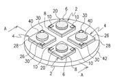
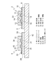
図1は本発明の実施例1に係る照明装置を示す斜視図、図2はそのA−A断面図、図3は白色光の色合いを示す色度図である。2は相関色温度が高い色合いの白色光を発光する第1LEDパッケージであり、4は相関色温度が低い色合いの白色光を発光する第2LEDパッケージである。
FIG. 1 is a perspective view showing an illumination apparatus according to Embodiment 1 of the present invention, FIG. 2 is a sectional view taken along the line AA, and FIG. 3 is a chromaticity diagram showing a hue of white light.
第1LEDパッケージ2は、表面に形成された導電パターン(図示せず)及び電極パッド10を有するガラスエポキシ、BTレジン、セラミックス、メタルコア等の絶縁材からなる基板6と、金ワイヤ12によって導電パターンを介して電極パッド10に接続されたInGaN系化合物半導体等を用いた青色LED14,16と、第1蛍光体18を配合したエポキシ樹脂、シリコン樹脂等の透明樹脂からなり青色LED14,16を封止する第1モールド樹脂20と、を備えている。
The
第1蛍光体18は、青色LED14,16が発する青色光に励起されて発光し、青色LED14,16からの青色光と混色することで相関色温度が高い色合いの白色光にするものである。本実施例における第1蛍光体18は、青色光により励起されて黄色系の蛍光を発するサイアロン等の黄色蛍光体からなる。このような青色LED14,16と第1蛍光体18を用いた第1LEDパッケージ2は、7000K〜6500Kの昼光色の色合いの白色光を発光することになる。
The
第2LEDパッケージ4は、第1LEDパッケージ2と同様に、表面に形成された導電パターン(図示せず)及び電極パッド30を有する絶縁材からなる基板26と、金ワイヤ32によって導電パターンを介して電極パッド30に接続された青色LED34,36と、第2蛍光体38を配合した透明樹脂からなり青色LED34,36を封止する第2モールド樹脂40と、を備えている。
Similarly to the
第2蛍光体38は、青色LED34,36が発する青色光に励起されて発光し、青色LED34,36からの青色光と混色することで相関色温度が低い色合いの白色光にするものである。本実施例における第2蛍光体38は、青色光により励起されて赤色系の蛍光を発するYAG等の赤色蛍光体からなる。このような青色LED34,36と第2蛍光体38を用いた第2LEDパッケージ4は、3000K〜2600Kの電球色の色合いの白色光を発光することになる。
The
42は照明器具等の筐体である。なお、図中の筐体42は、第1及び第2LEDパッケージ2,4の構成を明確に図示するため、第1及び第2LEDパッケージ2,4を取り付ける基板状部分のみを図示している。本実施例における照明装置は、筐体42に、アルミ製の放熱板8,28を介して、第1及び第2LEDパッケージ2,4が対をなすように多数のLEDパッケージが取り付けられている。図1に示す照明装置では第1及び第2LEDパッケージ2,4が2組、筐体42に取り付けられているが、必要とする明るさに応じて数十個から数百個のLEDパッケージが取り付けられる。また、本実施例においては、放熱板8,28は基板6,26と同じ平面形状の方形であり、その上面に基板6,26が固着されている。また、基板6,26には貫通孔が形成され、この貫通孔内に露出した放熱板8,28の上面に、前記青色LED14,16,34,36がそれぞれ実装されている。
次に、上記構成からなる照明装置における発光色の混色、調光とLEDの点灯制御について説明する。本実施例における照明装置の場合、第1及び第2LEDパッケージ2,4の電極パッド10,30にそれぞれ制御回路から電流が供給されて、青色LED14,16と青色LED34,36がそれぞれ点灯制御される。第1LEDパッケージ2の青色LED14,16が点灯すると、その青色光により励起された第1蛍光体18から黄色系の蛍光が発せられる。この蛍光は、青色光と混色されて相関色温度が高い色合いである昼光色の白色光を生じさせる。また、第2LEDパッケージ4の青色LED34,36が点灯すると、その青色光により励起された第2蛍光体38から赤色系の蛍光が発せられる。この蛍光は、青色光と混色されて相関色温度が低い色合いである電球色の白色光を生じさせる。
Next, a description will be given of color mixing of light emission colors, dimming, and LED lighting control in the lighting device having the above-described configuration. In the case of the lighting device according to the present embodiment, current is supplied from the control circuit to the
図3に示すように、昼光色の相関色温度は7000K〜6500Kであり、電球色の相関色温度は3000K〜2600Kである。このため、第1LEDパッケージ2だけを点灯させると相関色温度7000K〜6500Kの昼光色の白色光を発光することができ、第2LEDパッケージ4だけを点灯させると相関色温度3000K〜2600Kの電球色の白色光を発光することができる。
As shown in FIG. 3, the correlated color temperature of the daylight color is 7000K to 6500K, and the correlated color temperature of the light bulb color is 3000K to 2600K. For this reason, when only the
また、第1及び第2LEDパッケージ2,4を同時に点灯させると、昼光色の白色光と電球色の白色光を混色させて白色光の色合いを変えることができる。その際に、第1及び第2LEDパッケージ2,4の駆動電流をそれぞれ制御することで双方の明るさを調整することができ、それにより、昼光色と電球色の混色を制御することができる。このように、第1及び第2LEDパッケージ2,4の発光を制御すると、図3に示すように、昼光色と電球色を上下限とするライン44上の色合いの白色光を任意に調光することができる。このライン44上の色合いは、相関色温度7000K〜2600Kの昼光色、昼白色、白色、温白色、電球色であり、この範囲内で任意に色合いを調光することができる。
Further, when the first and
特に、第1及び第2LEDパッケージ2,4に使用している青色LED14,16,34,36は全て同じ青色光を発光する同一のLEDであるため、その順方向降下電圧VF、寿命、劣化スピードがほぼ同一となっている。このため、多数のLEDを使用しても、個々のLEDの順方向降下電圧等を考慮して制御する必要がない。
In particular, since the
なお、照明装置として十分な明るさを得るため、各LEDパッケージ内に複数の青色LED(本実施例では2個)を設けており、その数は任意に設定することが可能である。 In addition, in order to obtain sufficient brightness as a lighting device, a plurality of blue LEDs (two in this embodiment) are provided in each LED package, and the number can be arbitrarily set.
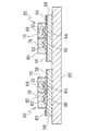
図4は本発明の実施例2に係る照明装置を示す断面図である。本実施例における照明装置は、単一のLEDパッケージで昼光色の白色光と電球色の白色光を発光して混色するように構成している。
FIG. 4 is a cross-sectional view showing an illumination apparatus according to
本実施例における混合LEDパッケージ50は、前述した実施例1における第1及び第2LEDパッケージ2,4と同様に、表面に形成された導電パターン(図示せず)及び電極パッド60を有する絶縁材からなる基板56と、金ワイヤ62によって導電パターンを介して電極パッド60に接続された青色LED64,66と、を備えている。一方、前述した第1及び第2LEDパッケージ2,4と異なり、本実施例における混合LEDパッケージ50では、青色LED64が第1蛍光体68を配合した透明樹脂からなる第1モールド樹脂70で封止され、青色LED66が第2蛍光体78を配合した透明樹脂からなる第2モールド樹脂80で封止されている。
The
本実施例における第1蛍光体68は、実施例1における第1蛍光体18と同じ黄色蛍光体からなるものであり、青色LED64からの青色光により励起されて発生し、青色LED64からの青色光と混色することで相関色温度が高い7000K〜6500Kの昼光色の色合いの白色光にするものとなっている。また、第2蛍光体78は、実施例1における第2蛍光体38と同じ赤色蛍光体からなるものであり、青色LED66からの青色光により励起されて発光し、青色LED66からの青色光と混色することで相関色温度が低い3000K〜2600Kの電球色の色合いの白色光にするものとなっている。
The
また、照明器具等の筐体82も実施例1における筐体42と同様のものとなっている。本実施例における筐体82には、基板56と同一形状の方形からなる放熱板58を介して、上記構成からなる混合LEDパッケージ50が複数取り付けられている。なお、本実施例においても、基板56に形成した貫通孔内において、露出した放熱板58の上面に、青色LED64,66がそれぞれ実装されている。
A
上記構成からなる本実施例の照明装置の場合、青色LED64,66にそれぞれ制御回路から電流が供給されてそれぞれ点灯制御される。青色LED64,66が点灯すると、その青色光によりそれぞれ励起された第1蛍光体68と第2蛍光体78から黄色系の蛍光と青色系の蛍光がそれぞれ発せられる。これらの蛍光は、それぞれ青色光と混色されて相関色温度が高い昼光色の白色光と相関色温度が低い電球色の白色光をそれぞれ生じさせる。
In the case of the lighting apparatus of the present embodiment having the above-described configuration, current is supplied to the
上記のように、混合LEDパッケージ50は、昼光色の白色光と電球色の白色光の両方を発光する。このため、混合LEDパッケージ50が発する光は、昼光色の白色光と電球色の白色光又はその白色光を混色することにより相関色温度7000K〜2600Kの範囲内における任意の色合いの白色光を発光することになる。
As described above, the
なお、図示した混合LEDパッケージ50においては、第1及び第2モールド樹脂70,80により1個ずつ青色LEDを封止しているが、十分な明るさを得るため複数の青色LEDをそれぞれ封止しても良い。
In the illustrated
また、実施例1における第1及び第2LEDパッケージ2,4と、実施例2における混合LEDパッケージ50の両方を筐体42,82に取り付けることも可能である。
It is also possible to attach both the first and
2 第1LEDパッケージ
4 第2LEDパッケージ
6、26 基板
8、28 放熱板
10、30 電極パッド
12、32 金ワイヤ
14、16、34、36 青色LED
18 第1蛍光体
20 第1モールド樹脂
38 第2蛍光体
40 第2モールド樹脂
42 筐体
50 混合LEDパッケージ
56 基板
58 放熱板
60 電極パッド
62 金ワイヤ
64、66 青色LED
68 第1蛍光体
70 第1モールド樹脂
78 第2蛍光体
80 第2モールド樹脂
82 筐体
2
18
68
Claims (8)
複数の青色発光ダイオードを、発光色の相関色温度が低くなるように第2蛍光体を配合した第2モールド樹脂にて封止することにより、相関色温度が低い色合いの白色光を発光する第2発光ダイオードパッケージと、
を備え、前記第1発光ダイオードパッケージと前記第2発光ダイオードパッケージの一方を点灯させるか又は両方を点灯制御することで、相関色温度が高い色合いの白色光から相関色温度が低い色合いの白色光までを発光することを特徴とする照明装置。 A plurality of blue light emitting diodes are sealed with a first mold resin containing a first phosphor so that the correlated color temperature of the luminescent color is increased, thereby emitting white light having a color with a high correlated color temperature. One light emitting diode package;
A plurality of blue light emitting diodes are sealed with a second mold resin containing a second phosphor so that the correlated color temperature of the emitted color is lowered, thereby emitting white light with a hue having a low correlated color temperature. Two light emitting diode packages;
And turning on one of the first light-emitting diode package and the second light-emitting diode package or controlling both to turn white light having a low correlated color temperature from white light having a high correlated color temperature. A lighting device characterized by emitting light up to.
前記青色発光ダイオードの第1部と第2部の一方を点灯させるか又は両方を点灯制御することで、相関色温度が高い色合いの白色光から相関色温度が低い色合いの白色光までを発光することを特徴とする照明装置。 The first part, which is a part of the plurality of blue light emitting diodes, is sealed with a first mold resin containing a first phosphor so that the correlated color temperature of the emitted color is increased, and the remaining part of the blue light emitting diodes By sealing a second part with a second mold resin containing a second phosphor so that the correlated color temperature of the emitted color is lowered, the white light having a high correlated color temperature and the correlated color temperature are increased. Equipped with multiple mixed light emitting diode packages that emit low shades of white light,
Either one of the first part and the second part of the blue light emitting diode is turned on or both are turned on to emit light from white light having a high correlated color temperature to white light having a low correlated color temperature. A lighting device characterized by that.
Priority Applications (2)
| Application Number | Priority Date | Filing Date | Title |
|---|---|---|---|
| JP2008299591A JP2010129583A (en) | 2008-11-25 | 2008-11-25 | Lighting fixture |
| US12/625,846 US8348457B2 (en) | 2008-11-25 | 2009-11-25 | Lighting device with light modulation for white light |
Applications Claiming Priority (1)
| Application Number | Priority Date | Filing Date | Title |
|---|---|---|---|
| JP2008299591A JP2010129583A (en) | 2008-11-25 | 2008-11-25 | Lighting fixture |
Publications (2)
| Publication Number | Publication Date |
|---|---|
| JP2010129583A true JP2010129583A (en) | 2010-06-10 |
| JP2010129583A5 JP2010129583A5 (en) | 2011-12-08 |
Family
ID=42222188
Family Applications (1)
| Application Number | Title | Priority Date | Filing Date |
|---|---|---|---|
| JP2008299591A Pending JP2010129583A (en) | 2008-11-25 | 2008-11-25 | Lighting fixture |
Country Status (2)
| Country | Link |
|---|---|
| US (1) | US8348457B2 (en) |
| JP (1) | JP2010129583A (en) |
Cited By (11)
| Publication number | Priority date | Publication date | Assignee | Title |
|---|---|---|---|---|
| JP2012174867A (en) * | 2011-02-21 | 2012-09-10 | Panasonic Corp | Light-emitting device and lighting apparatus using the same |
| WO2013094481A1 (en) * | 2011-12-19 | 2013-06-27 | シャープ株式会社 | Illumination device, ceiling light, backlight, liquid-crystal display, and television receiver |
| JP2014123465A (en) * | 2012-12-20 | 2014-07-03 | Panasonic Corp | Led lighting device and led light-emitting module |
| JP2015079924A (en) * | 2013-10-18 | 2015-04-23 | シチズン電子株式会社 | Semiconductor light-emitting device |
| JP2015146437A (en) * | 2011-05-27 | 2015-08-13 | シャープ株式会社 | Light-emitting device and illumination device |
| JP2016153873A (en) * | 2015-02-17 | 2016-08-25 | セイコーエプソン株式会社 | Wavelength conversion device, illumination device and projector |
| JP2016187035A (en) * | 2016-06-01 | 2016-10-27 | パナソニックIpマネジメント株式会社 | Light source device |
| JP2019510377A (en) * | 2016-03-24 | 2019-04-11 | ティーディーケイ・エレクトロニクス・アクチェンゲゼルシャフトTdk Electronics Ag | Multi LED system |
| JP2020504905A (en) * | 2016-12-30 | 2020-02-13 | ルミレッズ リミテッド ライアビリティ カンパニー | Improved phosphor deposition system for LEDs |
| US10950764B2 (en) | 2017-11-28 | 2021-03-16 | Nichia Corporation | Light-emitting device |
| US11257990B2 (en) | 2017-09-29 | 2022-02-22 | Nichia Corporation | Light emitting device |
Families Citing this family (15)
| Publication number | Priority date | Publication date | Assignee | Title |
|---|---|---|---|---|
| US8946987B2 (en) * | 2007-11-07 | 2015-02-03 | Industrial Technology Research Institute | Light emitting device and fabricating method thereof |
| CN102313249B (en) * | 2010-07-01 | 2014-11-26 | 惠州元晖光电股份有限公司 | Tunable white color methods and uses thereof |
| US10522518B2 (en) * | 2010-12-23 | 2019-12-31 | Bench Walk Lighting, LLC | Light source with tunable CRI |
| KR20130023841A (en) * | 2011-08-30 | 2013-03-08 | 엘지이노텍 주식회사 | Correlated color temperature controllable light emitting diode package controlled |
| JP5776599B2 (en) * | 2012-03-26 | 2015-09-09 | 東芝ライテック株式会社 | Light emitting module and lighting device |
| US9048367B2 (en) * | 2012-06-04 | 2015-06-02 | Brightek Optoelectronic Co., Ltd. | Multichip package structure for generating a symmetrical and uniform light-blending source |
| US9756726B2 (en) * | 2013-11-04 | 2017-09-05 | Infineon Technologies Ag | Electronic device and method of fabricating an electronic device |
| JP6230392B2 (en) * | 2013-11-29 | 2017-11-15 | シチズン電子株式会社 | Light emitting device |
| US9974138B2 (en) | 2015-04-21 | 2018-05-15 | GE Lighting Solutions, LLC | Multi-channel lamp system and method with mixed spectrum |
| US10598318B1 (en) * | 2016-06-14 | 2020-03-24 | Eaton Intelligent Power Limited | Light source and method for making a light source |
| KR102487411B1 (en) * | 2017-10-31 | 2023-01-12 | 엘지디스플레이 주식회사 | Light emitting device package, and electronic device |
| USD901752S1 (en) * | 2019-01-25 | 2020-11-10 | Eaton Intelligent Power Limited | Optical structure |
| US11236887B2 (en) | 2019-01-25 | 2022-02-01 | Eaton Intelligent Power Limited | Optical structures for light emitting diodes (LEDs) |
| USD903187S1 (en) * | 2019-01-25 | 2020-11-24 | Eaton Intelligent Power Limited | Optical structure |
| WO2021231932A1 (en) * | 2020-05-15 | 2021-11-18 | Lumileds Llc | Multi-color light source and methods of manufacture |
Citations (10)
| Publication number | Priority date | Publication date | Assignee | Title |
|---|---|---|---|---|
| JP2002335019A (en) * | 2001-03-05 | 2002-11-22 | Nichia Chem Ind Ltd | Light emitting device |
| JP2003152225A (en) * | 2001-08-28 | 2003-05-23 | Matsushita Electric Works Ltd | Light emitting device |
| JP2005153606A (en) * | 2003-11-21 | 2005-06-16 | Toyoda Gosei Co Ltd | Lighting system |
| JP2005167138A (en) * | 2003-12-05 | 2005-06-23 | Nec Lighting Ltd | White light emitting element |
| JP2006005290A (en) * | 2004-06-21 | 2006-01-05 | Citizen Electronics Co Ltd | Light emitting diode |
| JP2007243056A (en) * | 2006-03-10 | 2007-09-20 | Matsushita Electric Works Ltd | Light emitting device |
| JP2007294621A (en) * | 2006-04-24 | 2007-11-08 | Sharp Corp | Led lighting system |
| JP2008147190A (en) * | 2006-12-05 | 2008-06-26 | Samsung Electro-Mechanics Co Ltd | White light emitting device and white light source module using same |
| JP2008218485A (en) * | 2007-02-28 | 2008-09-18 | Toshiba Lighting & Technology Corp | Light emitting device |
| JP2008283155A (en) * | 2007-05-14 | 2008-11-20 | Sharp Corp | Light emitting device, lighting device, and liquid crystal display device |
Family Cites Families (15)
| Publication number | Priority date | Publication date | Assignee | Title |
|---|---|---|---|---|
| US6600175B1 (en) * | 1996-03-26 | 2003-07-29 | Advanced Technology Materials, Inc. | Solid state white light emitter and display using same |
| US6255670B1 (en) * | 1998-02-06 | 2001-07-03 | General Electric Company | Phosphors for light generation from light emitting semiconductors |
| US6127783A (en) | 1998-12-18 | 2000-10-03 | Philips Electronics North America Corp. | LED luminaire with electronically adjusted color balance |
| US6700322B1 (en) * | 2000-01-27 | 2004-03-02 | General Electric Company | Light source with organic layer and photoluminescent layer |
| US6515417B1 (en) * | 2000-01-27 | 2003-02-04 | General Electric Company | Organic light emitting device and method for mounting |
| US6661029B1 (en) * | 2000-03-31 | 2003-12-09 | General Electric Company | Color tunable organic electroluminescent light source |
| US6577073B2 (en) * | 2000-05-31 | 2003-06-10 | Matsushita Electric Industrial Co., Ltd. | Led lamp |
| AT410266B (en) * | 2000-12-28 | 2003-03-25 | Tridonic Optoelectronics Gmbh | LIGHT SOURCE WITH A LIGHT-EMITTING ELEMENT |
| US7153015B2 (en) * | 2001-12-31 | 2006-12-26 | Innovations In Optics, Inc. | Led white light optical system |
| US7005679B2 (en) * | 2003-05-01 | 2006-02-28 | Cree, Inc. | Multiple component solid state white light |
| US7564180B2 (en) * | 2005-01-10 | 2009-07-21 | Cree, Inc. | Light emission device and method utilizing multiple emitters and multiple phosphors |
| JP4679183B2 (en) | 2005-03-07 | 2011-04-27 | シチズン電子株式会社 | Light emitting device and lighting device |
| US7847302B2 (en) * | 2005-08-26 | 2010-12-07 | Koninklijke Philips Electronics, N.V. | Blue LED with phosphor layer for producing white light and different phosphor in outer lens for reducing color temperature |
| BRPI0620413A2 (en) * | 2005-12-21 | 2011-11-08 | Cree Led Lighting Solutions | lighting device and lighting method |
| JP5099418B2 (en) | 2006-11-30 | 2012-12-19 | 東芝ライテック株式会社 | Lighting device |
-
2008
- 2008-11-25 JP JP2008299591A patent/JP2010129583A/en active Pending
-
2009
- 2009-11-25 US US12/625,846 patent/US8348457B2/en active Active
Patent Citations (10)
| Publication number | Priority date | Publication date | Assignee | Title |
|---|---|---|---|---|
| JP2002335019A (en) * | 2001-03-05 | 2002-11-22 | Nichia Chem Ind Ltd | Light emitting device |
| JP2003152225A (en) * | 2001-08-28 | 2003-05-23 | Matsushita Electric Works Ltd | Light emitting device |
| JP2005153606A (en) * | 2003-11-21 | 2005-06-16 | Toyoda Gosei Co Ltd | Lighting system |
| JP2005167138A (en) * | 2003-12-05 | 2005-06-23 | Nec Lighting Ltd | White light emitting element |
| JP2006005290A (en) * | 2004-06-21 | 2006-01-05 | Citizen Electronics Co Ltd | Light emitting diode |
| JP2007243056A (en) * | 2006-03-10 | 2007-09-20 | Matsushita Electric Works Ltd | Light emitting device |
| JP2007294621A (en) * | 2006-04-24 | 2007-11-08 | Sharp Corp | Led lighting system |
| JP2008147190A (en) * | 2006-12-05 | 2008-06-26 | Samsung Electro-Mechanics Co Ltd | White light emitting device and white light source module using same |
| JP2008218485A (en) * | 2007-02-28 | 2008-09-18 | Toshiba Lighting & Technology Corp | Light emitting device |
| JP2008283155A (en) * | 2007-05-14 | 2008-11-20 | Sharp Corp | Light emitting device, lighting device, and liquid crystal display device |
Cited By (17)
| Publication number | Priority date | Publication date | Assignee | Title |
|---|---|---|---|---|
| JP2012174867A (en) * | 2011-02-21 | 2012-09-10 | Panasonic Corp | Light-emitting device and lighting apparatus using the same |
| US10088123B2 (en) | 2011-05-27 | 2018-10-02 | Sharp Kabushiki Kaisha | Light emitting device, LED light bulb, spot lighting device, lighting device, and lighting equipment |
| US9611985B2 (en) | 2011-05-27 | 2017-04-04 | Sharp Kabushiki Kaisha | Light emitting device, lighting device |
| JP2015146437A (en) * | 2011-05-27 | 2015-08-13 | シャープ株式会社 | Light-emitting device and illumination device |
| WO2013094481A1 (en) * | 2011-12-19 | 2013-06-27 | シャープ株式会社 | Illumination device, ceiling light, backlight, liquid-crystal display, and television receiver |
| JP2014123465A (en) * | 2012-12-20 | 2014-07-03 | Panasonic Corp | Led lighting device and led light-emitting module |
| JP2015079924A (en) * | 2013-10-18 | 2015-04-23 | シチズン電子株式会社 | Semiconductor light-emitting device |
| JP2016153873A (en) * | 2015-02-17 | 2016-08-25 | セイコーエプソン株式会社 | Wavelength conversion device, illumination device and projector |
| JP2019510377A (en) * | 2016-03-24 | 2019-04-11 | ティーディーケイ・エレクトロニクス・アクチェンゲゼルシャフトTdk Electronics Ag | Multi LED system |
| US10818641B2 (en) | 2016-03-24 | 2020-10-27 | Epcos Ag | Multi-LED system |
| JP2016187035A (en) * | 2016-06-01 | 2016-10-27 | パナソニックIpマネジメント株式会社 | Light source device |
| JP2020504905A (en) * | 2016-12-30 | 2020-02-13 | ルミレッズ リミテッド ライアビリティ カンパニー | Improved phosphor deposition system for LEDs |
| US10923635B2 (en) | 2016-12-30 | 2021-02-16 | Lumileds Llc | Phosphor deposition system for LEDs |
| JP6992073B2 (en) | 2016-12-30 | 2022-01-13 | ルミレッズ リミテッド ライアビリティ カンパニー | How to make a light emitting device |
| US11699777B2 (en) | 2016-12-30 | 2023-07-11 | Lumileds Llc | Phosphor deposition system for LEDs |
| US11257990B2 (en) | 2017-09-29 | 2022-02-22 | Nichia Corporation | Light emitting device |
| US10950764B2 (en) | 2017-11-28 | 2021-03-16 | Nichia Corporation | Light-emitting device |
Also Published As
| Publication number | Publication date |
|---|---|
| US8348457B2 (en) | 2013-01-08 |
| US20100134043A1 (en) | 2010-06-03 |
Similar Documents
| Publication | Publication Date | Title |
|---|---|---|
| JP2010129583A (en) | Lighting fixture | |
| US8884508B2 (en) | Solid state lighting device including multiple wavelength conversion materials | |
| US8212466B2 (en) | Solid state lighting devices including light mixtures | |
| US8664846B2 (en) | Solid state lighting device including green shifted red component | |
| US9515055B2 (en) | Light emitting devices including multiple anodes and cathodes | |
| JP4386693B2 (en) | LED lamp and lamp unit | |
| JP4989936B2 (en) | Lighting device | |
| JP5654328B2 (en) | Light emitting device | |
| EP2334147B1 (en) | Illumination device | |
| JP2008218485A (en) | Light emitting device | |
| KR20130063527A (en) | Led-based light emitting systems and devices | |
| US20080315217A1 (en) | Semiconductor Light Source and Method of Producing Light of a Desired Color Point | |
| JP2007027421A (en) | Led package and lighting device | |
| RU2691638C2 (en) | Lighting device, led strip, lamp and lighting device manufacturing method | |
| JP2007214603A (en) | Led lamp and lamp unit | |
| JP2009260319A (en) | Lighting device | |
| JP5828100B2 (en) | LIGHT EMITTING DEVICE AND LIGHTING DEVICE USING THE SAME | |
| JP2006080334A (en) | Led light emitting device | |
| JP2015106502A (en) | Luminaire | |
| US20200053852A1 (en) | Light emitting device | |
| JP2014194858A (en) | Led lighting device | |
| JP7296579B2 (en) | lighting equipment | |
| JP2014130728A (en) | Illuminating device |
Legal Events
| Date | Code | Title | Description |
|---|---|---|---|
| A521 | Written amendment |
Free format text: JAPANESE INTERMEDIATE CODE: A523 Effective date: 20111025 |
|
| A621 | Written request for application examination |
Free format text: JAPANESE INTERMEDIATE CODE: A621 Effective date: 20111025 |
|
| A131 | Notification of reasons for refusal |
Free format text: JAPANESE INTERMEDIATE CODE: A131 Effective date: 20130319 |
|
| A521 | Written amendment |
Free format text: JAPANESE INTERMEDIATE CODE: A523 Effective date: 20130515 |
|
| A131 | Notification of reasons for refusal |
Free format text: JAPANESE INTERMEDIATE CODE: A131 Effective date: 20140225 |
|
| A521 | Written amendment |
Free format text: JAPANESE INTERMEDIATE CODE: A523 Effective date: 20140423 |
|
| A131 | Notification of reasons for refusal |
Free format text: JAPANESE INTERMEDIATE CODE: A131 Effective date: 20141111 |
|
| A02 | Decision of refusal |
Free format text: JAPANESE INTERMEDIATE CODE: A02 Effective date: 20150310 |