JP2010099237A - Game machine - Google Patents

Game machine Download PDF

Info

Publication number
JP2010099237A
JP2010099237A JP2008272940A JP2008272940A JP2010099237A JP 2010099237 A JP2010099237 A JP 2010099237A JP 2008272940 A JP2008272940 A JP 2008272940A JP 2008272940 A JP2008272940 A JP 2008272940A JP 2010099237 A JP2010099237 A JP 2010099237A
Authority
JP
Japan
Prior art keywords
driving force
game
auxiliary
effect operation
link
Prior art date
Legal status (The legal status is an assumption and is not a legal conclusion. Google has not performed a legal analysis and makes no representation as to the accuracy of the status listed.)
Granted
Application number
JP2008272940A
Other languages
Japanese (ja)
Other versions
JP4909335B2 (en
Inventor
Masahiro Saito
正広 齋藤
Current Assignee (The listed assignees may be inaccurate. Google has not performed a legal analysis and makes no representation or warranty as to the accuracy of the list.)
Sophia Co Ltd
Original Assignee
Sophia Co Ltd
Priority date (The priority date is an assumption and is not a legal conclusion. Google has not performed a legal analysis and makes no representation as to the accuracy of the date listed.)
Filing date
Publication date
Application filed by Sophia Co Ltd filed Critical Sophia Co Ltd
Priority to JP2008272940A priority Critical patent/JP4909335B2/en
Publication of JP2010099237A publication Critical patent/JP2010099237A/en
Application granted granted Critical
Publication of JP4909335B2 publication Critical patent/JP4909335B2/en
Expired - Fee Related legal-status Critical Current
Anticipated expiration legal-status Critical

Links

Images

Abstract

<P>PROBLEM TO BE SOLVED: To provide a game machine efficiently disposing a plurality of movable members and having an auxiliary presentation operating generator adapted to perform new presentation operation even when the plurality of (e.g., three) movable members are disposed. <P>SOLUTION: A driving force of a driving source (a second driving motor 62) is transmitted to a second operating part (a chest part 662) and a third operating part (an abdomen part 663) by a second driving force transmitting member 615, and a first operating part (a face part 661) is caused to perform an operation different from those of the second operating part and the third operating part. <P>COPYRIGHT: (C)2010,JPO&INPIT

Description

本発明は、所定の演出動作を行う補助演出動作役物と、補助演出動作役物の演出動作を制御する演出制御手段と、を備えた遊技機に関する。   The present invention relates to a gaming machine provided with an auxiliary effect operation accessory for performing a predetermined effect operation and an effect control means for controlling the effect operation of the auxiliary effect operation accessory.

従来の遊技機、例えば、パチンコ遊技機においては、遊技盤に遊技球が流下可能な遊技領域を区画形成し、該遊技領域の略中央に装飾等の機能を備えた包囲枠としてセンターケースを配置し、該センターケースの奥側に変動表示装置(映像表示装置)としての液晶表示装置を配置している。また、センターケースの下方には、始動入賞口等の始動入賞領域を設定し、遊技球が始動入賞領域へ入賞すると、変動表示装置に複数の識別情報を変動表示して変動表示ゲームを実行する。
そして、センターケースに演出動作を実行可能な補助演出動作役物(演出装置)を配置し、該補助演出動作役物は、単一のモータによって複数の可動部材を可動させることにより、遊技の興趣を増大させ、かつ小型化を達成し得るように構成したパチンコ遊技機が提案されている(例えば、特許文献1参照)。
特開2004−129875号公報
In a conventional gaming machine, such as a pachinko gaming machine, a game area where a game ball can flow down is defined on the game board, and a center case is arranged as a surrounding frame having a function such as decoration in the approximate center of the game area. In addition, a liquid crystal display device as a variable display device (video display device) is disposed on the back side of the center case. Also, a start winning area such as a start winning opening is set below the center case, and when the game ball wins the start winning area, a plurality of identification information is displayed in a variable display on the variable display device to execute a variable display game. .
Then, an auxiliary production operation accessory (production device) capable of performing the production operation is arranged in the center case, and the auxiliary production operation agent moves a plurality of movable members by a single motor, thereby making the game interesting. There has been proposed a pachinko gaming machine configured to increase the size and achieve a reduction in size (see, for example, Patent Document 1).
JP 2004-129875 A

しかしながら、上記特許文献1の場合、モータからの駆動力を伝達する伝達手段を各可動部材がそれぞれ備えなければならないため、可動部材が増えるに連れて伝達手段も増え、効率良く可動部材を配置することが困難であった。   However, in the case of the above-mentioned Patent Document 1, each movable member must be provided with transmission means for transmitting the driving force from the motor. Therefore, as the number of movable members increases, the number of transmission means increases, and the movable members are arranged efficiently. It was difficult.

本発明の目的は、複数(例えば3つ)の可動部材を設けた場合であっても、この複数の可動部材をそれぞれ効率良く配置するとともに斬新な演出動作を行わせる補助演出動作役物を備える遊技機を提供するものである。   An object of the present invention is to provide an auxiliary effect operation accessory that efficiently arranges each of the plurality of movable members and performs a novel effect operation even when a plurality of (for example, three) movable members are provided. A game machine is provided.

以上の課題を解決するため、請求項1に記載の発明は、
所定の演出動作を行う補助演出動作役物と、前記補助演出動作役物の演出動作を制御する演出制御手段と、を備えた遊技機において、
前記補助演出動作役物は、
補助演出動作部と、
前記補助演出動作部を駆動させる駆動源と、
前記駆動源を取り付けるための駆動源取付ベース部材と、
を備え、
前記補助演出動作部は、第1動作部と、第2動作部と、第3動作部と、を備え、
前記駆動源取付ベース部材は、
前記駆動源の駆動力を前記第1動作部に伝達する第1駆動力伝達部材と、
前記駆動源の駆動力を前記第2動作部及び前記第3動作部に伝達する第2駆動力伝達部材と、
を備え、
前記駆動源が駆動して前記第2駆動力伝達部材へ駆動力を伝達させることによって、前記第2動作部及び前記第3動作部の動作を開始させ、
前記第2動作部及び前記第3動作部の動作開始後、前記第2駆動力伝達部材へ伝達させる駆動力を前記第1駆動力伝達部材へも伝達させることによって、前記第1動作部の動作を開始させることを特徴とする。
In order to solve the above problems, the invention described in claim 1
In a gaming machine comprising: an auxiliary performance operation accessory that performs a predetermined performance operation; and an effect control means that controls the performance operation of the auxiliary performance operation character.
The auxiliary production action character is:
Auxiliary production operation part,
A drive source for driving the auxiliary effect operation unit;
A drive source mounting base member for mounting the drive source;
With
The auxiliary performance operation unit includes a first operation unit, a second operation unit, and a third operation unit,
The drive source mounting base member is
A first driving force transmission member that transmits the driving force of the driving source to the first operating unit;
A second driving force transmitting member that transmits the driving force of the driving source to the second operating unit and the third operating unit;
With
The driving source is driven to transmit the driving force to the second driving force transmitting member, thereby starting the operations of the second operating unit and the third operating unit,
After the operation of the second operation unit and the third operation unit is started, the operation of the first operation unit is transmitted by transmitting the driving force transmitted to the second driving force transmission member to the first driving force transmission member. Is started.

請求項1に記載の発明によれば、第2駆動力伝達部材によって、駆動源の駆動力を第2動作部と第3動作部とに伝達することができるとともに、この伝達により第2動作部と第3動作部との動作が開始した後、第2駆動力伝達部材へ伝達させる駆動力を第1駆動力伝達部材へも伝達させることによって、第1動作部の動作を開始させることができるので、各動作部毎に伝達部材を備える必要がなくなり、複数の動作部(可動部材)をそれぞれ効率良く構成するとともに伝達部材の数が増えることによるコストを削減でき、また、斬新な演出動作を行わせることができるようになる。   According to the first aspect of the present invention, the driving force of the driving source can be transmitted to the second operating unit and the third operating unit by the second driving force transmitting member, and the second operating unit is transmitted by this transmission. After the operation of the first operation unit is started, the operation of the first operation unit can be started by transmitting the driving force transmitted to the second driving force transmission member also to the first driving force transmission member. Therefore, it is not necessary to provide a transmission member for each operation part, and a plurality of operation parts (movable members) can be configured efficiently, and the cost due to the increase in the number of transmission members can be reduced, and a novel production operation can be performed. Can be made to do.

ここで、遊技機には、パチンコ遊技機、アレンジボール遊技機、雀球遊技機などの弾球遊技機や、パチスロ或いはスロットマシーンなどが含まれる。   Here, the gaming machine includes a ball ball gaming machine such as a pachinko gaming machine, an arrangement ball gaming machine, and a sparrow ball gaming machine, a pachislot machine or a slot machine.

請求項2に記載の発明は、請求項1に記載の遊技機であって、
前記第2駆動力伝達部材は、
前記駆動源による回転動力を伝達するクランクと、
前記クランクと、前記第2動作部と、を接続する第1連結部と、
前記クランクと、前記第3動作部と、を接続する第2連結部と、
を備え、
前記第1連結部は、長孔状の第1リンク孔を備え、
前記第2連結部は、前記第1リンク孔の長手方向の長さよりも長い長孔を有する第2リンク孔を備え、
前記クランクは、
前記第1リンク孔に係合するとともに当該第1リンク孔を摺動する第1リンクピンと、
前記第2リンク孔に係合するとともに当該第2リンク孔を摺動する第2リンクピンと、
を備えることを特徴とする。
The invention according to claim 2 is the gaming machine according to claim 1,
The second driving force transmission member is
A crank for transmitting rotational power by the drive source;
A first connecting portion connecting the crank and the second operating portion;
A second connecting portion connecting the crank and the third operating portion;
With
The first connecting portion includes a long hole-shaped first link hole,
The second connecting portion includes a second link hole having a long hole longer than a length in a longitudinal direction of the first link hole,
The crank is
A first link pin that engages with the first link hole and slides in the first link hole;
A second link pin that engages with the second link hole and slides in the second link hole;
It is characterized by providing.

請求項2に記載の発明によれば、駆動源による回転動力によってクランクが回転した際、該クランクに備えられた第1リンクピン及び第2リンクピンに摺動されて第1リンク孔を備える第1連結部及び第2リンク孔を備える第2連結部が可動することとなる。また、第2リンク孔は、第1リンク孔の長手方向の長さよりも長い長孔を有するので、第1連結部が可動し終わっても、第2連結部はさらに、可動を続けることとなる。
従って、第2駆動力伝達部材によって駆動源の駆動力を第2動作部と第3動作部とに伝達することによって、第2動作部と第3動作部とを可動させ、さらに第3動作部だけを可動させることができることとなり、補助演出動作役物によって斬新な演出効果を奏することができるようになる。
According to the second aspect of the present invention, when the crank is rotated by the rotational power from the drive source, the first link hole and the second link pin provided in the crank are slid and provided with the first link hole. A 2nd connection part provided with 1 connection part and a 2nd link hole will move. In addition, since the second link hole has a long hole longer than the length of the first link hole in the longitudinal direction, the second connection portion continues to move even after the first connection portion has been moved. .
Accordingly, by transmitting the driving force of the driving source to the second operating part and the third operating part by the second driving force transmitting member, the second operating part and the third operating part are moved, and the third operating part is further moved. As a result, it is possible to produce a novel production effect by the auxiliary production operation accessory.

請求項3に記載の発明は、請求項2に記載の遊技機であって、
前記補助演出動作役物は、前記補助演出動作部が設けられる補助演出動作役物本体部を備え、
前記第1駆動力伝達部材は、
前記駆動源による回転動力を伝達するアームと、
前記アームと、前記第1動作部と、を接続するとともに前記アームによる回転運動を直線運動に変換する変換部材と、
を備え、
前記補助演出動作役物本体部は、
前記変換部材に接続された前記第1動作部が前記直線運動する方向に対して所定の角度をなす傾斜面を有する突出片を備え、
前記第1動作部は、
前記傾斜面に当接する当接ピンと、
当該第1動作部を回動させる回動軸部と、
前記回動軸部と、前記変換部材と、を接続する連結片と、
を備え、
前記当接ピンは、前記第1動作部が前記直線運動した際、前記傾斜面に当接することを特徴とする。
The invention according to claim 3 is the gaming machine according to claim 2,
The auxiliary effect operation character includes an auxiliary effect operation character main body provided with the auxiliary effect operation part,
The first driving force transmission member is
An arm for transmitting rotational power by the drive source;
A conversion member that connects the arm and the first operating unit and converts rotational motion by the arm into linear motion;
With
The auxiliary production operation accessory main body is
A projecting piece having an inclined surface that forms a predetermined angle with respect to the linearly moving direction of the first operating portion connected to the conversion member;
The first operation unit includes:
A contact pin that contacts the inclined surface;
A rotating shaft portion for rotating the first operating portion;
A connecting piece connecting the pivot shaft and the conversion member;
With
The abutment pin abuts on the inclined surface when the first operation unit moves linearly.

請求項3に記載の発明によれば、駆動源の駆動力によって、第1動作部は直線運動を行うだけではなく、補助演出動作役物本体部に備えられた突出片の傾斜面に沿っても運動するので、第1動作部は回動軸部を中心として回動することとなり、補助演出動作役物によって、より斬新な演出効果を奏することができるようになる。   According to the third aspect of the present invention, the first operation unit not only performs a linear motion by the driving force of the drive source, but also along the inclined surface of the protruding piece provided in the auxiliary effect operation accessory main body. Therefore, the first operation part rotates about the rotation shaft part, so that a more novel effect can be produced by the auxiliary effect operation accessory.

請求項4に記載の発明は、請求項3に記載の遊技機であって、
複数の識別情報を変動表示する変動表示ゲームを表示画面にて実行する変動表示装置を備え、
前記演出制御手段は、
前記変動表示装置の表示制御を行うとともに、前記変動表示装置において実行される変動表示ゲームに基づいて前記補助演出動作役物による所定の演出動作の制御を行い、
前記補助演出動作役物が所定の演出動作を行った場合に、前記表示画面に特定の演出表示をさせることを特徴とする。
The invention according to claim 4 is the gaming machine according to claim 3,
A variable display device for executing a variable display game for variable display of a plurality of identification information on a display screen,
The production control means includes
While performing display control of the variable display device, based on a variable display game executed in the variable display device, to control a predetermined effect operation by the auxiliary effect operation agent,
A specific effect display is displayed on the display screen when the auxiliary effect operation accessory performs a predetermined effect operation.

請求項4に記載の発明によれば、演出制御手段によって、変動表示装置の表示制御を行うとともに、変動表示装置において実行される変動表示ゲームに基づいて補助演出動作役物による所定の演出動作の制御を行い、補助演出動作役物が所定の演出動作を行った場合に、表示画面に特定の演出表示をさせることができるので、変動表示装置における演出表示と補助演出動作役物における演出が融合した従来にない斬新な演出を実現することができるようになる。   According to the fourth aspect of the present invention, the display control of the variable display device is performed by the effect control means, and a predetermined effect operation by the auxiliary effect operation accessory is performed based on the variable display game executed in the variable display device. When the control effect is performed and the auxiliary effect operation accessory performs a predetermined effect operation, a specific effect display can be displayed on the display screen, so the effect display on the variable display device and the effect on the auxiliary effect operation accessory are fused. It will be possible to realize a novel production that has never been achieved before.

ここで、識別情報には、数字、文字、記号およびキャラクタ、並びに、色彩など、視覚により識別可能な識別図柄(識別標識)等が含まれる。
また、変動表示装置は、液晶表示装置、CRT(陰極線管)表示装置などの単体の装置であっても、また、これら装置と多数の発光素子を配列した表示装置、回転ドラムを使用したメカ式の表示装置などとの組み合わせでもよく、画像表示可能な領域を含んでいればよい。
Here, the identification information includes numbers, letters, symbols and characters, and identification patterns (identification marks) that can be visually identified, such as colors.
The variable display device may be a single device such as a liquid crystal display device or a CRT (cathode ray tube) display device, or a display device in which these devices and a large number of light emitting elements are arranged, and a mechanical type using a rotating drum. The display device may be combined with the display device or the like as long as the image display area is included.

本発明によれば、第2駆動力伝達部材によって、駆動源の駆動力を第2動作部と第3動作部とに伝達することができるので、各動作部毎に伝達部材を備える必要がなくなり、複数の動作部(可動部材)をそれぞれ効率良く構成するとともに好適に駆動させることができるようになる。   According to the present invention, since the driving force of the driving source can be transmitted to the second operating unit and the third operating unit by the second driving force transmitting member, it is not necessary to provide a transmitting member for each operating unit. The plurality of operating parts (movable members) can be configured efficiently and driven appropriately.

以下、この発明の実施形態について図面を参照して説明する。
ここでは、本発明にかかる遊技機の適例としてのパチンコ遊技機について説明を行う。
Embodiments of the present invention will be described below with reference to the drawings.
Here, a pachinko gaming machine as a suitable example of the gaming machine according to the present invention will be described.

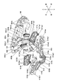
図1に示すように、本実施の形態のパチンコ遊技機100は、内部の遊技領域1a内に遊技球を発射して(弾球して)遊技を行うもので、その前側上半部のガラス板の奥側には、遊技領域1aを構成する遊技盤1が設置されている。   As shown in FIG. 1, the pachinko gaming machine 100 according to the present embodiment is a game in which a game ball is fired (bulleted) into an internal game area 1a, and the front upper half of the glass is a glass. A game board 1 constituting a game area 1a is installed on the back side of the board.

遊技盤1は、各種部材の取付ベースとなる平板状の遊技盤本体1b(木製もしくは合成樹脂製)を備え、該遊技盤本体1bの前面に、ガイドレール2で囲まれた遊技領域1aを有している。また、遊技盤本体1bの前面であってガイドレール2の外側には、前面構成部材3,3,…が取り付けられている。そして、このガイドレール2で囲まれた遊技領域1a内に発射装置から遊技球(打球;遊技媒体)を発射して遊技を行うようになっている。   The game board 1 includes a flat game board main body 1b (made of wood or synthetic resin) that serves as a mounting base for various members, and has a game area 1a surrounded by guide rails 2 on the front surface of the game board main body 1b. is doing. Further, front structural members 3, 3,... Are attached to the front surface of the game board main body 1b and outside the guide rail 2. Then, a game ball (hit ball; game medium) is launched from the launching device into the game area 1a surrounded by the guide rail 2 to play a game.

遊技領域1a内には、普図始動ゲート4と、普図の変動表示ゲームを表示する普図表示器5(図2に図示)が設けられている。また、遊技領域1a内には、第1始動入賞口13(入賞装置)と、第2始動入賞口(入賞装置)としての普通変動入賞装置7(入賞装置)と、補助遊技としての特図変動表示ゲームを表示する特図表示器9(図2に図示)が設けられている。   In the game area 1a, there is provided a general diagram start gate 4 and a general diagram display 5 (shown in FIG. 2) for displaying a normal variation display game. Further, in the game area 1a, a first start winning opening 13 (winning apparatus), a normal variable winning apparatus 7 (winning apparatus) as a second starting winning opening (winning apparatus), and a special figure change as an auxiliary game. A special display 9 (shown in FIG. 2) for displaying the display game is provided.

また、遊技領域1aの略中央には、変動表示ゲームの表示領域となる窓部22を形成するセンターケース20が取り付けられている。このセンターケース20に形成された窓部22の後方には、表示装置41が配設されるようになっている。この表示装置41は、例えば、液晶ディスプレイを備え、表示内容が変化可能な表示部42がセンターケース20の窓部22を介して遊技盤1の前面側から視認可能となるように配設されている。なお、表示装置41は、液晶ディスプレイを備えるものに限らず、EL、CRT等のディスプレイを備えるものであっても良い。   In addition, a center case 20 that forms a window 22 serving as a display area for the variable display game is attached to the approximate center of the game area 1a. A display device 41 is arranged behind the window portion 22 formed in the center case 20. The display device 41 includes, for example, a liquid crystal display, and is arranged so that a display unit 42 whose display contents can be changed is visible from the front side of the game board 1 through the window 22 of the center case 20. Yes. The display device 41 is not limited to the one provided with a liquid crystal display, and may be provided with a display such as an EL or CRT.

また、図1に示すように、センターケース20の右側には、表示装置41において実行される変動表示ゲームに基づいて所定の演出動作を行う演出動作役物50が配設されるとともに、当該所定の演出動作において補助的な演出動作を行う補助演出動作役物600,700,800が、それぞれ、センターケース20の上部、左側上部及び右側下部に配設されている。   Further, as shown in FIG. 1, on the right side of the center case 20, an effect operation accessory 50 that performs a predetermined effect operation based on a variable display game executed on the display device 41 is disposed. In the production operation, auxiliary production operation accessories 600, 700, and 800 that perform an auxiliary production operation are disposed on the upper portion, the upper left portion, and the lower right portion of the center case 20, respectively.

また、図1に示すように、センターケース20には、当該センターケース20の左側上部に配設された補助演出動作役物700の下方にワープ入口25が配設されており、センターケース20の外側の遊技領域1aを流下する遊技球を流入可能とし、このワープ入口25から流入した遊技球をセンターケース20の内側に排出させるワープ出口26等を備えている。   In addition, as shown in FIG. 1, the center case 20 is provided with a warp inlet 25 below the auxiliary effect operating accessory 700 provided on the upper left side of the center case 20. A game ball flowing down the outer game area 1 a is allowed to flow in, and a warp outlet 26 for discharging the game ball flowing in from the warp inlet 25 to the inside of the center case 20 is provided.

さらに遊技領域1aには、特別変動入賞装置10が配設されており、上端側が手前側に倒れる方向に回動して開放可能になっているアタッカ形式の開閉扉10aによって開閉される大入賞口を備えていて、特別遊技状態中は、大入賞口を閉じた状態から開いた状態に変換することにより大入賞口内への遊技球の流入を容易にさせる。なお、開閉扉10aは、例えば、駆動装置としてのソレノイド(大入賞口開閉SOL10b、図2に図示)により駆動される。また、大入賞口の内部(入賞領域)には、該大入賞口に入った遊技球を検出するカウントSW10c(図2に図示)が配設されている。   Further, the game area 1a is provided with a special variable winning device 10, which is opened and closed by an attacker-type opening / closing door 10a that can be opened by rotating in a direction in which the upper end side is tilted forward. In the special gaming state, the game ball is easily flowed into the prize winning opening by converting the prize winning opening from the closed state to the opened state. The open / close door 10a is driven by, for example, a solenoid (a special prize opening / closing SOL 10b, shown in FIG. 2) as a driving device. In addition, a count SW 10c (shown in FIG. 2) for detecting a game ball that has entered the big prize opening is disposed inside the big prize opening (winning area).

また、遊技領域1aに設けられた各一般入賞口12には、一般入賞口12に入った遊技球を検出するための入賞口SW12a(図2に図示)が配設されている。そして、遊技を開始することにより遊技領域1a内に打ち込まれた遊技球が、一般入賞口12,12,…、普通変動入賞装置7、第1始動入賞口13、特別変動入賞装置10等の入賞口の何れかに入賞すると、それぞれの入賞口に対応した所定数の賞球が排出装置によって排出される(払い出される)ようになっている。この他、遊技領域1aには、入賞口などに入賞しなかった遊技球を回収するアウト穴11、打球方向変換部材としての風車15、多数の障害釘などが配設されている。   In addition, in each general winning opening 12 provided in the game area 1a, a winning opening SW 12a (shown in FIG. 2) for detecting a game ball that has entered the general winning opening 12 is disposed. The game balls that are driven into the game area 1a by starting the game are awarded to the general prize opening 12, 12,..., The normal variable prize winning device 7, the first start prize winning port 13, the special variable prize winning device 10, etc. When a prize is won in any of the mouths, a predetermined number of prize balls corresponding to the respective prize mouths are discharged (paid out) by the discharging device. In addition, the game area 1a is provided with an out hole 11 for collecting game balls that have not won a winning opening, a windmill 15 as a hitting direction changing member, a number of obstacle nails, and the like.

普図始動ゲート4内には、該普図始動ゲート4を通過した遊技球を検出するためのゲートSW4a(図2に図示)が設けられている。そして、遊技領域1a内に打ち込まれた遊技球が普図始動ゲート4内を通過すると、普図変動表示ゲームが行われる。また、普図変動表示ゲームを開始できない状態、例えば、既に普図変動表示ゲームが行われ、その普図変動表示ゲームが終了していない状態や、普図変動表示ゲームが当って普通変動入賞装置7が開状態に変換されている場合に、普図始動ゲート4を遊技球が通過すると、普図始動記憶数の上限数未満でならば、普図始動記憶数が1加算されて普図始動記憶が1つ記憶されることとなる。   A gate SW4a (shown in FIG. 2) for detecting a game ball that has passed through the general diagram start gate 4 is provided in the general diagram start gate 4. Then, when the game ball that has been driven into the game area 1a passes through the normal diagram start gate 4, a normal variation display game is performed. In addition, the normal variation display game cannot be started, for example, the normal variation display game has already been played and the normal variation display game has not ended, or the normal variation display game has been hit and the normal variation winning device When 7 is converted to the open state and the game ball passes through the general figure starting gate 4, if the number is less than the upper limit of the general figure starting memory number, the normal figure starting memory number is incremented by one and the normal figure starting is started. One memory is stored.

普図(普通図柄)変動表示ゲームは、遊技領域1a内に設けられた普図表示器5(図2に図示)で実行されるようになっている。なお、表示装置41の表示領域の一部で普図変動表示ゲームを表示するようにしても良く、この場合は識別図柄として、例えば、数字、記号、キャラクタ図柄などを用い、これを所定時間変動表示させた後、停止表示させることにより行うようにする。この普図変動表示ゲームの停止表示が特別の結果態様となれば、普図の当りとなって、普通変動入賞装置7の開閉部材7a,7aが所定時間(例えば、0.5秒間)開放される。これにより、普通変動入賞装置7に遊技球が入賞しやすくなり、特図の変動表示ゲームの始動が容易となる。   The general-purpose (ordinary symbol) variation display game is executed by a general-purpose display 5 (shown in FIG. 2) provided in the game area 1a. In addition, you may make it display a common figure change display game in a part of display area of the display apparatus 41, In this case, for example, a number, a symbol, a character design etc. are used as an identification symbol, and this is changed for a predetermined time. After being displayed, it is performed by stopping display. If this stop display of the normal figure change display game becomes a special result mode, the open / close members 7a and 7a of the normal variable winning device 7 are opened for a predetermined time (for example, 0.5 seconds). The Thereby, it becomes easy to win a game ball in the normal variation winning device 7, and it becomes easy to start a special display variation display game.

普通変動入賞装置7は左右一対の開閉部材7a,7aを具備し、第1始動入賞口13の下部に配設され、この開閉部材7a,7aは、常時は遊技球の直径程度の間隔をおいて閉じた状態(遊技者にとって不利な状態)を保持しているが、普図変動表示ゲームの結果が所定の停止表示態様となった場合には、駆動装置としてのソレノイド(普電SOL7b、図2に図示)によって、逆「ハ」の字状に開いて普通変動入賞装置7に遊技球が流入し易い状態(遊技者にとって有利な状態)に変化させられるようになっている。   The normal variation winning device 7 includes a pair of left and right opening / closing members 7a, 7a, and is disposed below the first start winning opening 13, and the opening / closing members 7a, 7a are normally spaced at an interval of about the diameter of a game ball. However, when the result of the general variable display game is in a predetermined stop display mode, a solenoid (general power SOL 7b, FIG. 2), the game ball can be changed to a state in which the game ball can easily flow into the normal variation winning device 7 (a state advantageous to the player).

また、本実施形態のパチンコ遊技機100は、特図変動表示ゲームの結果態様に基づき、遊技状態として時短状態を発生可能となっている。この時短状態においては、上述の普図変動表示ゲームの実行時間が上述の長い実行時間よりも短くなるように制御され(例えば、10秒が1秒)、これにより、単位時間当りの普通変動入賞装置7の開放回数が実質的に多くなるように制御される。また、時短状態においては、普図変動表示ゲームが当り結果となって普通変動入賞装置7が開放される場合に、開放時間が通常状態の短い開放時間より長くされるように制御される(例えば、0.3秒が1.8秒)。また、時短状態においては、普図変動表示ゲームの1回の当り結果に対して、普通変動入賞装置7が1回ではなく、複数回(例えば、2回)開放される。さらに、時短状態においては普図変動表示ゲームの当り結果となる確率が通常状態より高くなるように制御される。すなわち、通常状態よりも普通変動入賞装置7の開放回数が増加される。   In addition, the pachinko gaming machine 100 according to the present embodiment can generate a short time state as a gaming state based on a result aspect of the special figure variation display game. In this short state, the execution time of the above-described normal variation display game is controlled so as to be shorter than the above-described long execution time (for example, 10 seconds is 1 second). Control is performed so that the number of times the device 7 is opened is substantially increased. Also, in the short time state, when the normal variation winning game 7 is released as a result of the normal fluctuation display game, the control is performed so that the opening time is longer than the short opening time of the normal state (for example, 0.3 seconds is 1.8 seconds). In the short-time state, the normal variation winning device 7 is opened a plurality of times (for example, twice) instead of once for the result of one hit of the normal variation display game. Furthermore, in the short time state, the probability that the hit result of the normal map display game is higher than that in the normal state is controlled. That is, the number of times of opening of the normally variable winning device 7 is increased as compared with the normal state.

この第1始動入賞口13および普通変動入賞装置7は、特図変動表示ゲームの始動入賞口も兼ねている。すなわち、第1始動入賞口13の内部(入賞領域)に備えられた第1始動口SW13d、および、普通変動入賞装置7の内部(入賞領域)に備えられた第2始動口SW7d(図2に図示)によって遊技球を検出することに基づき、補助遊技としての特図変動表示ゲームを開始する始動権利が発生するようになっている。   The first start winning opening 13 and the normal variation winning apparatus 7 also serve as a start winning opening for the special figure variation display game. That is, the first start opening SW13d provided in the inside of the first start winning opening 13 (winning area) and the second start opening SW7d provided in the inside (winning area) of the normal variation winning apparatus 7 (in FIG. 2). Based on the detection of a game ball by (shown), a right to start a special figure variation display game as an auxiliary game is generated.

この特図変動表示ゲームを開始する始動権利は、所定の上限数(例えば4)の範囲内で始動記憶(特図始動記憶)として記憶される。従って、特図変動表示ゲームが開始可能な状態で、且つ、始動記憶数が0の状態で、普通変動入賞装置7および第1始動入賞口13の何れかに遊技球が入賞すると、始動権利の発生に伴って始動記憶が記憶されて、始動記憶数が1加算されるととともに、直ちに始動記憶に基づいて、特図変動表示ゲームが開始され、この際に始動記憶数が1減算される。   The right to start the special figure variation display game is stored as a start memory (special figure start memory) within a predetermined upper limit (for example, 4). Therefore, when a special ball fluctuation display game can be started and the number of starting memories is 0, and a game ball wins either the normal fluctuation winning device 7 or the first starting winning opening 13, The start memory is stored with the occurrence, the start memory number is incremented by 1, and the special figure variation display game is immediately started based on the start memory. At this time, the start memory number is decremented by 1.

一方、特図変動表示ゲームが直ちに開始できない状態、例えば、既に特図変動表示ゲームが行われ、その特図変動表示ゲームが終了していない状態や、特別遊技状態となっている場合に、普通変動入賞装置7および第1始動入賞口13の何れかに遊技球が入賞すると、始動記憶数が上限数未満ならば、始動記憶数が1加算されて始動記憶が1つ記憶されることになる。そして、始動記憶数が1以上となった状態で、特図変動表示ゲームが開始可能な状態(前回の特図変動表示ゲームの終了もしくは特別遊技状態の終了)となると、始動記憶数が1減算されるとともに、記憶された始動記憶に基づいて特図変動表示ゲームが開始される。   On the other hand, it is normal when the special figure fluctuation display game cannot be started immediately, for example, when the special figure fluctuation display game has already been performed and the special figure fluctuation display game has not been completed or is in the special game state. When a game ball wins either the variable winning device 7 or the first start winning port 13, if the start memory number is less than the upper limit number, the start memory number is incremented by 1 and one start memory is stored. . Then, when the number of starting memories becomes 1 or more, when the state where the special figure variation display game can be started (the end of the previous special figure variation display game or the end of the special game state) is reached, the number of starting memories is decremented by 1. At the same time, the special figure variation display game is started based on the stored start memory.

特図変動表示ゲームは、遊技領域1a内に設けられた特図表示器9(図2に図示)で実行されるようになっており、複数の図柄を変動表示したのち、所定の結果態様を停止表示することで行われる。また、表示装置41にて複数種類の図柄(例えば、数字、記号、キャラクタ図柄など)を変動表示させる特図変動表示ゲームに対応した飾り特図変動表示ゲームが実行されるようになっている。そして、この特図変動表示ゲームの結果として、特図表示器9の表示態様が特別結果態様(たとえば「7」)となった場合には、大当りとなって特別遊技状態(いわゆる、大当り状態)となる。また、これに対応して表示装置41の表示態様も特別結果態様(例えば、「7,7,7」等のゾロ目数字の何れか)となる。また、普通変動入賞装置7への遊技球の入賞に基づく特図(特別図柄)変動表示ゲームにおいては、第1始動入賞口13への遊技球の入賞に基づく特図変動表示ゲームよりも、大当りへの期待度が高い演出が行われるようになっている。なお、遊技機に特図表示器9を備えずに、表示装置41のみで特図変動表示ゲームを実行するようにしても良い。   The special figure variation display game is executed by a special figure display device 9 (shown in FIG. 2) provided in the game area 1a. After a plurality of symbols are variably displayed, a predetermined result mode is displayed. This is done by displaying a stop. In addition, a decoration special figure variation display game corresponding to a special figure variation display game in which a plurality of types of symbols (for example, numbers, symbols, character symbols, etc.) are displayed in a variable manner on the display device 41 is executed. And, as a result of this special figure variation display game, when the display mode of the special figure display 9 becomes a special result mode (for example, “7”), it becomes a big hit and a special game state (so-called big hit state) It becomes. Correspondingly, the display mode of the display device 41 also becomes a special result mode (for example, any one of the numbers in the flat order such as “7, 7, 7”). Further, in the special figure (special symbol) fluctuation display game based on the winning of the game ball to the normal fluctuation winning device 7, the big hit is larger than the special figure fluctuation display game based on the winning of the game ball to the first start winning opening 13. Productions with high expectations are being made. Note that the special-figure display game may be executed only by the display device 41 without providing the special-figure display 9 in the gaming machine.

また、本実施形態のパチンコ遊技機100は、特図変動表示ゲームの結果態様に基づき、遊技状態として確変(確率変動)状態を発生可能となっている。この確変状態においては、上述の時短状態に加え、特図変動表示ゲームの当り結果となる確率が通常状態より高くなるように制御される。   Further, the pachinko gaming machine 100 according to the present embodiment can generate a probable change (probability change) state as a game state based on the result form of the special figure change display game. In this probability change state, in addition to the above-mentioned time-short state, the probability that the hit result of the special figure variation display game is higher than the normal state is controlled.

また、図2に示すように、パチンコ遊技機100は、その制御系として遊技の進行を制御する遊技制御装置30、この遊技制御装置30の制御下で各種の演出に関する制御を行うサブ制御装置としての演出制御装置40を備えている。   As shown in FIG. 2, the pachinko gaming machine 100 is a game control device 30 that controls the progress of the game as its control system, and a sub-control device that controls various effects under the control of the game control device 30. The production control device 40 is provided.

遊技制御装置30は、CPUやROM、RAMなどを備える遊技用ワンチップマイコン30aを備えるとともに、入力インタフェース(入力I/F)32、出力インタフェース(出力I/F)33、外部通信端子31等により構成されている。   The game control device 30 includes a game one-chip microcomputer 30a including a CPU, a ROM, a RAM, and the like, and includes an input interface (input I / F) 32, an output interface (output I / F) 33, an external communication terminal 31, and the like. It is configured.

遊技用ワンチップマイコン30aは、内部のCPUが制御部、演算部を備え、演算制御を行う他、特図変動表示ゲームの大当り判定用乱数値などの各種乱数値なども生成している。
また、CPUは、第1始動口SW13dや第2始動口SW7dによる遊技球の検出に従って出力された検出信号が入力されると、RAMに始動入賞として記憶させる。即ち、第1始動入賞口13、普通変動入賞装置7に遊技球が入賞することにより、第1始動口SW13d、第2始動口SW7dから検出信号が出力され、CPUに入力されると、CPUは、第1始動入賞口13、普通変動入賞装置7に対する遊技球の入賞を検出する。
In the gaming one-chip microcomputer 30a, an internal CPU includes a control unit and a calculation unit, and performs calculation control, and also generates various random number values such as a jackpot determination random number value of a special figure variation display game.
Further, when a detection signal output according to the detection of the game ball by the first start port SW13d or the second start port SW7d is input, the CPU stores the start prize in the RAM. That is, when a game ball wins the first start winning opening 13 and the normal variation winning apparatus 7, detection signals are output from the first starting opening SW13d and the second starting opening SW7d and are input to the CPU. The winning of the game ball to the first start winning opening 13 and the normal variation winning apparatus 7 is detected.

また、CPUは、始動入賞に基づいて特図変動表示ゲーム(飾り特図変動表示ゲーム)を開始させる際に、当該特図変動表示ゲームの変動パターン、即ち、識別情報の変動表示時間を含む変動パターンやリーチパターン(リーチアクションの種類)を決定する。   Further, when the CPU starts the special figure fluctuation display game (decoration special figure fluctuation display game) based on the start winning prize, the fluctuation including the fluctuation pattern of the special figure fluctuation display game, that is, the fluctuation display time of the identification information. Determine patterns and reach patterns (reach action types).

遊技用ワンチップマイコン30aの内部のRAMには、第1始動入賞口13、普通変動入賞装置7に設けられた第1始動口SW13d、普通変動入賞装置7に設けられた第2始動口SW7dのオン信号などを記憶する記憶領域や、前記各種乱数値の記憶領域、並びに、CPUの作業領域等を備えている。即ち、RAMには、CPUにより検出された遊技球の入賞が始動入賞として記憶されるようになっている。   The RAM inside the game one-chip microcomputer 30a includes a first start winning port 13, a first starting port SW13d provided in the normal variation winning device 7, and a second starting port SW7d provided in the normal variation winning device 7. A storage area for storing an ON signal, a storage area for the various random values, a work area for the CPU, and the like are provided. In other words, the game ball winning detected by the CPU is stored in the RAM as a start winning.

遊技用ワンチップマイコン30aの内部のROMには、遊技上の制御プログラムや制御データが書き込まれている他、上述の各種乱数値に対応して、特図変動表示ゲームの大当り発生を判定するための、特図変動表示ゲームの大当り判定値、変動パターン、リーチパターン(リーチアクションの種類)の判定値などが記憶されている。   In addition to the game control program and control data being written in the ROM inside the gaming one-chip microcomputer 30a, in order to determine the occurrence of the big hit of the special figure variation display game corresponding to the various random numbers described above. The jackpot judgment value, fluctuation pattern, reach pattern (type of reach action) judgment value, etc. of the special figure fluctuation display game are stored.

また、入力インタフェース32には、ローパスフィルタ及びバッファーゲートを介して、第1始動口SW13d、第2始動口SW7d、入賞口SW12a,…、ゲートSW4a、カウントSW10c、ガラス枠開放SW146、内枠開放SW121、球切れSW122などが接続されている。そして、入力インタフェース32は、これらから入力された各種信号を中継し、遊技用ワンチップマイコン30aに対し出力する。
なお、ガラス枠開放SW146は、クリア部材保持枠が開放されていることを検出するものであり、内枠開放SW121は、前面枠が開放されていることを検出するものである。また、球切れSW122は、島設備から供給された遊技球を排出装置に誘導するシュートに設けられ、シュート内の遊技球がなくなったことを検出するものである。
The input interface 32 is connected to a first start port SW13d, a second start port SW7d, a winning port SW12a,..., A gate SW4a, a count SW10c, a glass frame opening SW146, and an inner frame opening SW121 via a low pass filter and a buffer gate. In addition, a ball break SW 122 and the like are connected. The input interface 32 relays various signals input from these and outputs them to the gaming one-chip microcomputer 30a.
The glass frame opening SW 146 detects that the clear member holding frame is opened, and the inner frame opening SW 121 detects that the front frame is opened. The ball break SW 122 is provided on a chute that guides the game ball supplied from the island facility to the discharge device, and detects that there is no game ball in the chute.

また、出力インタフェース33には、遊技用ワンチップマイコン30aから出力される各種の制御信号が入力される。これら制御信号は、該出力インタフェース33により中継されて、図示しない出力ポート及びドライバを介して、特図表示器9、普図表示器5、普電SOL7b、大入賞口SOL10b、遊技機外部の管理装置などと接続する外部端子板16、排出制御装置125、演出制御装置40に出力される。   The output interface 33 receives various control signals output from the game one-chip microcomputer 30a. These control signals are relayed by the output interface 33, and via a non-illustrated output port and driver, the special signal display 9, the general signal display 5, the general electric power SOL 7b, the big prize opening SOL 10b, the management outside the gaming machine It is output to the external terminal board 16 connected to the device, the discharge control device 125, and the effect control device 40.

演出制御装置40は、演算処理用CPU、ROM、RAM及びVDP等を備えるとともに、通信インタフェース(通信I/F)、出力インタフェース(出力I/F)等により構成されている。
演出制御装置40は、通信インタフェースを介して遊技制御装置30から受信した演出制御データ、演出動作役物50の駆動を検出する位置検出センサ532b(図2に図示)による検出信号に基づいて(遊技制御装置30の制御の下に)、パチンコ遊技機100の制御を行うものである。また、演出動作役物50を駆動させる第1駆動モータ52、補助演出動作役物600を駆動させる第2駆動モータ62、演出動作役物50に備えられた第1発光素子基板512(図2に図示)、第2発光素子基板514(図2に図示)、表示装置41、遊技盤1に設けられた各種LED基板144、スピーカ145,157等が接続され、遊技制御装置30の制御の下にこれらを制御することで遊技の演出を行うようになっている。
The effect control device 40 includes an arithmetic processing CPU, ROM, RAM, VDP, and the like, and includes a communication interface (communication I / F), an output interface (output I / F), and the like.
The effect control device 40 is based on the effect control data received from the game control device 30 via the communication interface, and a detection signal from the position detection sensor 532b (shown in FIG. 2) that detects the drive of the effect operation accessory 50 (game). The pachinko gaming machine 100 is controlled under the control of the control device 30. In addition, the first drive motor 52 that drives the effect operation accessory 50, the second drive motor 62 that drives the auxiliary effect operation accessory 600, and the first light emitting element substrate 512 provided in the effect operation accessory 50 (see FIG. 2). 2), a second light emitting element substrate 514 (shown in FIG. 2), a display device 41, various LED substrates 144 provided on the game board 1, speakers 145, 157, etc. are connected and under the control of the game control device 30. By controlling these, the game is rendered.

これらの制御回路においては、以下のような遊技制御が行われる。
遊技制御装置30の遊技用ワンチップマイコン30aでは、普図始動ゲート4に備えられたゲートSW4aからの遊技球の検出信号の入力に基づき、普図の当り判定用乱数値を抽出してROMに記憶されている判定値と比較し、普図変動表示ゲームの当り外れを判定する処理を行う。そして、普図表示器5に、識別図柄を所定時間変動表示した後、停止表示する普図変動表示ゲームを表示する処理を行う。この普図変動表示ゲームの結果が当りの場合は、普図表示器5に特別の結果態様を表示するとともに、普電SOL7bを動作させ、普通変動入賞装置7の開閉部材7a,7aを所定時間(例えば、0.5秒間)上述のように開放する制御を行う。
なお、普図変動表示ゲームの結果がはずれの場合は、普図表示器5にはずれの結果態様を表示する制御を行う。
In these control circuits, the following game control is performed.
The game one-chip microcomputer 30a of the game control device 30 extracts the random number value for hit determination of the normal figure based on the input of the detection signal of the game ball from the gate SW4a provided in the normal figure start gate 4, and stores it in the ROM. Compared with the stored determination value, a process of determining whether or not the normal-game fluctuation display game is missed is performed. Then, after the identification symbol is variably displayed for a predetermined time on the general symbol display 5, a process for displaying a general symbol variation display game to be stopped is performed. If the result of this normal map change display game is a win, a special result mode is displayed on the general map display 5 and the general electric power SOL 7b is operated to open and close the opening / closing members 7a, 7a of the normal variable winning device 7 for a predetermined time. The opening control is performed as described above (for example, for 0.5 seconds).
In addition, when the result of the normal map change display game is out of order, control is performed to display the result form of the shift on the general map display 5.

また、第1始動入賞口13に備えられた第1始動口SW13d、普通変動入賞装置7に備えられた第2始動口SW7dからの遊技球の検出信号の入力に基づき始動入賞(始動記憶)を記憶し、この始動記憶に基づき、特図変動表示ゲームの大当り判定用乱数値を抽出してROMに記憶されている判定値と比較し、特図変動表示ゲームの当り外れを判定する処理を行う。   In addition, the start winning (starting memory) is made based on the input of the detection signal of the game ball from the first starting port SW13d provided in the first starting winning port 13 and the second starting port SW7d provided in the normal variation winning device 7. Based on this start-up memory, the big hit determination random number value of the special figure variation display game is extracted and compared with the determination value stored in the ROM to determine whether the special figure fluctuation display game has been hit or lost. .

そして、遊技制御装置30は、上記の特図変動表示ゲームの判定結果を含む制御信号(演出制御コマンド)を、演出制御装置40に出力する。そして、特図表示器9に、識別図柄を所定時間変動表示した後、停止表示する特図変動表示ゲームを表示する処理を行う。
また、演出制御装置40では、遊技制御装置30からの制御信号に基づき、表示装置41で特図変動表示ゲームに対応した飾り特図変動表示ゲームを表示する処理を行う。ここで、演出制御装置40は、遊技制御装置(遊技制御手段)30からの制御指令に基づいて、変動表示装置としての表示装置41における飾り特図変動表示ゲームの表示制御及び演出動作役物50の演出動作を制御する演出制御手段を構成している。
さらに、演出制御装置40では、遊技制御装置30からの制御信号に基づき、スピーカ145,157からの音の出力、各種LED基板144のLEDの発光を制御する処理を行う。
Then, the game control device 30 outputs a control signal (effect control command) including the determination result of the special figure variation display game to the effect control device 40. Then, the special symbol display 9 performs a process of displaying the special symbol variation display game to be stopped and displayed after the identification symbol is variably displayed for a predetermined time.
In addition, in the effect control device 40, based on the control signal from the game control device 30, the display device 41 performs a process of displaying a decoration special figure change display game corresponding to the special figure change display game. Here, based on the control command from the game control device (game control means) 30, the effect control device 40 performs display control and effect operation accessory 50 for the decorative special figure variable display game on the display device 41 as the variable display device. The production control means for controlling the production operation is configured.
Further, the effect control device 40 performs a process of controlling the sound output from the speakers 145 and 157 and the light emission of the LEDs of the various LED boards 144 based on the control signal from the game control device 30.

そして、遊技制御装置30の遊技用ワンチップマイコン30aは、特図変動表示ゲームの結果が当りの場合は、特図表示器9に特別の結果態様を表示するとともに、特別遊技状態を発生させる処理を行う。
特別遊技状態を発生させる処理においては、例えば、大入賞口SOL10bにより特別変動入賞装置10の開閉扉10aを開放し、大入賞口内への遊技球の流入を可能とする制御を行う。そして、大入賞口に所定個数(例えば10個)の遊技球が入賞するか、大入賞口の開放から所定時間(例えば25秒または1秒)が経過するかの何れかの条件が達成されるまで大入賞口を開放することを1ラウンドとし、これを所定ラウンド回数(例えば15回または2回)継続する(繰り返す)制御(サイクル遊技)を行う。
なお、特図変動表示ゲームの結果がはずれの場合は、特図表示器9にはずれの結果態様を表示する制御を行う。
Then, the game one-chip microcomputer 30a of the game control device 30 displays a special result mode on the special figure display 9 and generates a special gaming state when the result of the special figure variation display game is winning. I do.
In the process of generating the special game state, for example, the opening / closing door 10a of the special variable winning device 10 is opened by the special winning opening SOL10b, and control is performed so that the gaming ball can flow into the special winning opening. Then, a condition that either a predetermined number (for example, 10) of game balls wins the grand prize opening or a predetermined time (for example, 25 seconds or 1 second) elapses from the opening of the big prize opening is achieved. Opening the grand prize winning opening is defined as one round, and control (cycle game) is performed to continue (repeat) this for a predetermined number of rounds (for example, 15 times or 2 times).
In addition, when the result of the special figure fluctuation display game is out of place, the special figure display unit 9 is controlled to display the result form of the deviation.

また、遊技制御装置30の遊技用ワンチップマイコン30aは、各種入賞口に設けられたセンサ(第1始動口SW13d、第2始動口SW7d、入賞口SW12a、カウントSW10c)から入力される遊技球の検出信号に基づき、排出制御装置125の払出モータを制御して所定数の遊技球が払い出されるようにする。   In addition, the game one-chip microcomputer 30a of the game control device 30 receives game balls input from sensors (first starting port SW13d, second starting port SW7d, winning port SW12a, count SW10c) provided at various winning ports. Based on the detection signal, the payout motor of the discharge control device 125 is controlled so that a predetermined number of game balls are paid out.

以下に、本実施の形態のパチンコ遊技機100におけるセンターケース20、センターケース20に配設された補助演出動作役物600、及び、当該補助演出動作役物600による演出動作について説明する。   Hereinafter, the center case 20 in the pachinko gaming machine 100 according to the present embodiment, the auxiliary effect operation accessory 600 disposed in the center case 20, and the effect operation by the auxiliary effect operation accessory 600 will be described.

センターケース20は、図3に示すように、前側に配設される前面構成部材200と、図4に示すように、後側に配設される後面構成部材300と、から構成されている。このうち、前面構成部材200は、枠状の前側ベース部材201を有し、この前側ベース部材201は、周面を形成する周囲壁202を有し、この周囲壁202にネジ穴やネジ止め部、位置決めのためのボス、ボスを受け入れる凹部やリブを受け入れるスリットなどが形成され、各種部材を適切な位置に固定できるようになっている。また、周囲壁202の前端部には、該周囲壁202に対して垂直に外側に向かって延出する鍔状の取付ベース203が形成されている。   As shown in FIG. 3, the center case 20 is composed of a front structural member 200 disposed on the front side and a rear structural member 300 disposed on the rear side as shown in FIG. Among these, the front structural member 200 has a frame-shaped front base member 201, and the front base member 201 has a peripheral wall 202 that forms a peripheral surface, and the peripheral wall 202 has screw holes and screwing portions. A boss for positioning, a recess for receiving the boss, a slit for receiving the rib, and the like are formed so that various members can be fixed at appropriate positions. In addition, a hook-shaped mounting base 203 is formed at the front end of the peripheral wall 202 and extends outwardly perpendicularly to the peripheral wall 202.

また、前側ベース部材201の下側の内周面には、ステージを構成する第1ステージ部204が備えられている。この第1ステージ部204の上面は、略W字状の傾斜面となっているとともに、第1ステージ部204の上面の左右方向の中央部分は、遊技球を第1始動入賞口13および普通変動入賞装置7に誘導するように前方に傾斜している。   In addition, a first stage portion 204 constituting a stage is provided on the inner peripheral surface of the lower side of the front base member 201. The upper surface of the first stage portion 204 is a substantially W-shaped inclined surface, and the central portion in the left-right direction of the upper surface of the first stage portion 204 is used to place the game ball on the first start winning opening 13 and the normal variation. It is inclined forward so as to be guided to the winning device 7.

取付ベース203は、遊技盤1に形成された開口の周縁よりも外側に延出するように形成されており、開口にセンターケース20を前面側から挿入した際に、遊技盤1の前面にその裏面が当接するようになっている。これによって、遊技盤1に対するセンターケース20の前後位置が所定の前後位置に設定されるようになっている。また、この取付ベース203には、前後に貫通するネジ孔が複数形成されており、ネジによってセンターケース20を遊技盤1に固定できるようになっている。さらに、取付ベース203は、遊技盤1の前面側であって遊技者から視認可能な位置に配設されるものであり、その前面には装飾が施されている。   The mounting base 203 is formed to extend outward from the periphery of the opening formed in the game board 1, and when the center case 20 is inserted into the opening from the front side, the attachment base 203 is placed on the front surface of the game board 1. The back surface comes into contact. Thereby, the front-rear position of the center case 20 with respect to the game board 1 is set to a predetermined front-rear position. The mounting base 203 is formed with a plurality of screw holes penetrating in the front-rear direction so that the center case 20 can be fixed to the game board 1 with screws. Furthermore, the mounting base 203 is disposed on the front side of the game board 1 at a position that can be visually recognized by the player, and the front surface is decorated.

また、前側ベース部材201の前面側には鎧部材212が取り付けられている。この鎧部材212は、センターケース20の上部および側部において、前方に向かって遊技領域1a内に突出するように配設され、鎧部材212の前端が遊技領域1aの前側を覆うガラス枠の内側のガラス板の裏面近傍に配設される。そして、鎧部材212は、遊技領域1aを流下する遊技球が、センターケース20の上側および側部から凹室27に進入するのを防止し、表示装置41の視認性を確保するとともに第1ステージ部204上への遊技球の流入数を制限するようになっている。また、前側ベース部材201の前面側から見て右側の側部には、補助演出動作役物800が配設されている。   An armor member 212 is attached to the front side of the front base member 201. The armor member 212 is disposed on the upper and side portions of the center case 20 so as to protrude forward into the game area 1a, and the front end of the armor member 212 covers the front side of the game area 1a. It is arrange | positioned in the back surface vicinity of this glass plate. The armor member 212 prevents the game ball flowing down the game area 1a from entering the concave chamber 27 from the upper side and the side part of the center case 20, thereby ensuring the visibility of the display device 41 and the first stage. The number of game balls flowing into the unit 204 is limited. In addition, an auxiliary performance operation accessory 800 is disposed on the right side as viewed from the front side of the front base member 201.

また、前側ベース部材201の前面側から見て左側の側部には、上述したワープ入口25が配設されており、ワープ入口25に流入した遊技球は、後述する後面構成部材300に配設されたワープ流路Aを通り、ワープ出口26から排出されるようになっている。   In addition, the warp inlet 25 described above is disposed on the left side as viewed from the front side of the front base member 201, and the game ball that has flowed into the warp inlet 25 is disposed in a rear surface component 300 described later. It passes through the warped flow path A and is discharged from the warp outlet 26.

図4に示すように、後面構成部材300は、枠状の後側ベース部材301を有し、この後側ベース部材301に各種の部材が取り付けられている。この後側ベース部材301はセンターケース20の後端部に位置するものであって、中央に矩形状の窓部22を有するとともに、該窓部22の後端が透明な材質からなる保護パネルによって覆われている。この後側ベース部材301の裏面に表示装置41の前面が当接した状態で固定されることで、表示装置41の表示領域が区画されるようになっている。また、この窓部22の周囲であって、後側ベース部材301の前面および裏面には、ネジ穴やネジ止め部、位置決めのためのボス、ボスを受け入れる凹部やリブなどが形成され、各種部材を適切な位置に固定できるようになっている。   As shown in FIG. 4, the rear surface component 300 includes a frame-shaped rear base member 301, and various members are attached to the rear base member 301. The rear base member 301 is located at the rear end of the center case 20 and has a rectangular window portion 22 in the center, and the rear end of the window portion 22 is formed by a protective panel made of a transparent material. Covered. The display area of the display device 41 is partitioned by being fixed with the front surface of the display device 41 in contact with the back surface of the rear base member 301. In addition, screw holes, screwing portions, bosses for positioning, recesses and ribs for receiving the bosses, and the like are formed around the window portion 22 on the front and back surfaces of the rear base member 301. Can be fixed in an appropriate position.

後側ベース部材301の前面には、該後側ベース部材301の前側をちょうど覆うように、透明な材質からなる枠状レンズ部材304が取り付けられている。この枠状レンズ部材304の中央には、後側ベース部材301に形成された窓部22に対応するように矩形状の開口が形成されている。また、この矩形状の開口の周囲には、前面側から見て上部には、補助演出動作役物600が配設され、また、前面側から見て左側には、補助演出動作役物700が配設され、さらに、前面側から見て下部右側には、演出動作役物50が配設されている。   A frame-shaped lens member 304 made of a transparent material is attached to the front surface of the rear base member 301 so as to just cover the front side of the rear base member 301. A rectangular opening is formed at the center of the frame-shaped lens member 304 so as to correspond to the window portion 22 formed in the rear base member 301. In addition, around this rectangular opening, an auxiliary effect operation accessory 600 is disposed on the upper side when viewed from the front side, and an auxiliary effect operation accessory 700 is provided on the left side when viewed from the front side. In addition, a rendering operation accessory 50 is disposed on the lower right side when viewed from the front side.

また、枠状レンズ部材304の外周には、前方へ延出する板状の周囲壁304aが形成されている。そして、この周囲壁304aの前端部が前面構成部材200に接続するようになっている。すなわち、後面構成部材300においては後側ベース部材301の前側に枠状レンズ部材304が配設され、さらに、その前側に前面構成部材200が配設されている。そして、後側ベース部材301の外周壁301aの外周面と枠状レンズ部材304の周囲壁304aの外周面、および前側ベース部材201の周囲壁202の外周面は、略同一面を形成するようになっている。   A plate-like peripheral wall 304 a extending forward is formed on the outer periphery of the frame-shaped lens member 304. The front end portion of the peripheral wall 304a is connected to the front structural member 200. That is, in the rear surface component 300, the frame-shaped lens member 304 is disposed on the front side of the rear base member 301, and the front surface component 200 is disposed on the front side thereof. The outer peripheral surface of the outer peripheral wall 301a of the rear base member 301, the outer peripheral surface of the peripheral wall 304a of the frame-shaped lens member 304, and the outer peripheral surface of the peripheral wall 202 of the front base member 201 are formed to be substantially the same surface. It has become.

また、枠状レンズ部材304の下側の内周面には、ステージを構成する第2ステージ部312と、該第2ステージ部312の後方には、第2ステージ部312よりも高い位置に第3ステージ部313が備えられている。この第2ステージ部312および第3ステージ部313は、上述した第1ステージ部204と同様に、その上面が、遊技球が転動する面とされ、枠状レンズ部材304の下側の内周面に沿って配設されている。   Further, a second stage portion 312 constituting the stage is provided on the lower inner peripheral surface of the frame-shaped lens member 304, and the second stage portion 312 is positioned behind the second stage portion 312 at a position higher than the second stage portion 312. A three-stage unit 313 is provided. Similar to the first stage unit 204 described above, the second stage unit 312 and the third stage unit 313 have an upper surface as a surface on which a game ball rolls, and an inner periphery on the lower side of the frame-shaped lens member 304. It is arranged along the surface.

また、枠状レンズ部材304の前面側から見て左側の側部には、上述したワープ出口26が配設されており、該ワープ出口26から排出された遊技球は、第2ステージ部312および第3ステージ部313を転動し、第1ステージ部204へと導かれるようになっている。また、このワープ出口26は、第3ステージ部313の上面よりも遊技球1個分程度、高い位置に配設されており、ワープ出口26から第3ステージ部313の上面に排出された遊技球は、勢いよく流出され、遊技者に遊技球の転動を楽しませることができるようになっている。   Further, the warp outlet 26 described above is disposed on the left side as viewed from the front side of the frame-shaped lens member 304, and the game balls discharged from the warp outlet 26 are stored in the second stage portion 312 and the second stage portion 312. The third stage unit 313 rolls and is guided to the first stage unit 204. The warp outlet 26 is disposed at a position higher by about one game ball than the upper surface of the third stage portion 313, and the game ball discharged from the warp outlet 26 to the upper surface of the third stage portion 313. The game is drained vigorously so that the player can enjoy rolling the game ball.

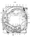
次に、図5〜15に示すように、補助演出動作役物600の構成について説明する。
この補助演出動作役物600は、駆動源としての第2駆動モータ62を取り付けるための駆動源取付ベース部材610と、補助演出動作役物本体部640と、所定の演出動作を行う補助演出動作部660と、を備えている。
Next, as shown in FIGS. 5 to 15, the configuration of the auxiliary effect operation accessory 600 will be described.
The auxiliary effect operation accessory 600 includes a drive source attachment base member 610 for attaching the second drive motor 62 as a drive source, an auxiliary effect operation accessory main body 640, and an auxiliary effect operation portion that performs a predetermined effect operation. 660.

駆動源取付ベース部材610は、図5,6に示すように、略矩形状の平板部材により構成されている。駆動源取付ベース部材610の略中央には、第2駆動モータ62の駆動軸62aを挿通するための挿通孔611が設けられており、当該駆動源取付ベース部材610の前面側から駆動軸62aを挿通孔611に挿通させることができるようになっている。また、駆動源取付ベース部材610には、当該駆動源取付ベース部材610の前面側から駆動軸62aを挿通孔611に挿通させた際、第2駆動モータ62に備えられたネジ孔62b,62bに対向するようにネジ孔612,612が設けられている。そして、このネジ孔62b,62bと、ネジ孔612,612と、を介してネジ(図示省略)により螺着することで駆動源取付ベース部材610に第2駆動モータ62を取り付けられるようになっている。   As shown in FIGS. 5 and 6, the drive source mounting base member 610 is configured by a substantially rectangular flat plate member. An insertion hole 611 for inserting the drive shaft 62a of the second drive motor 62 is provided in the approximate center of the drive source attachment base member 610. The drive shaft 62a is connected to the drive source attachment base member 610 from the front side. It can be inserted through the insertion hole 611. Further, when the drive shaft 62a is inserted into the insertion hole 611 from the front side of the drive source attachment base member 610, the drive source attachment base member 610 is inserted into the screw holes 62b and 62b provided in the second drive motor 62. Screw holes 612 and 612 are provided so as to face each other. The second drive motor 62 can be attached to the drive source attachment base member 610 by screwing with screws (not shown) through the screw holes 62b and 62b and the screw holes 612 and 612. Yes.

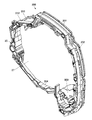
また、図6に示すように、駆動源取付ベース部材610の裏面側には、第2駆動モータ62による回転駆動力を伝達する駆動力伝達歯車613と、駆動力伝達歯車613に伝達された回転駆動力を第1動作部としての顔部661に伝達する第1駆動力伝達部材614と、駆動力伝達歯車613に伝達された回転駆動力を第2動作部としての胸部662及び第3動作部としての腹部663に伝達する第2駆動力伝達部材615と、を備えている。   Further, as shown in FIG. 6, on the back side of the drive source mounting base member 610, a drive force transmission gear 613 that transmits the rotational drive force by the second drive motor 62, and the rotation transmitted to the drive force transmission gear 613. A first driving force transmission member 614 that transmits the driving force to the face 661 as the first operation unit, and a chest 662 and a third operation unit as the second operation unit that transmit the rotational driving force transmitted to the driving force transmission gear 613. And a second driving force transmission member 615 that transmits to the abdomen 663.

駆動力伝達歯車613は、図6に示すように、欠歯歯車で構成されており、この駆動力伝達歯車613の軸受613aに駆動軸62aが挿着されるようになっている。また、駆動力伝達歯車613の欠歯部分には、アーム613bが径方向外向きに備えられている。そして、このアーム613bの先端部後面には、軸受613aに駆動軸62aが挿着された際に当該駆動軸62aに対して平行となるように円柱状のピン613cが備えられている。そして、このピン613cは、第1駆動力伝達部材614としての変換部材614aに設けられたガイド孔614bに挿通されるようになっている。そして、このとき、アーム613bは、第1駆動力伝達部材614の一構成として機能することとなる。   As shown in FIG. 6, the driving force transmission gear 613 is constituted by a toothless gear, and the driving shaft 62 a is inserted into a bearing 613 a of the driving force transmission gear 613. In addition, an arm 613b is provided radially outward in the toothless portion of the driving force transmission gear 613. A columnar pin 613c is provided on the rear surface of the tip of the arm 613b so as to be parallel to the drive shaft 62a when the drive shaft 62a is inserted into the bearing 613a. And this pin 613c is penetrated by the guide hole 614b provided in the conversion member 614a as the 1st driving force transmission member 614. As shown in FIG. At this time, the arm 613b functions as one configuration of the first driving force transmission member 614.

第1駆動力伝達部材614は、上述したアーム613bと、変換部材614aと、を備えて構成されている。図6に示すように、変換部材614aは、略矩形状の平板部材により構成されており、変換部材614aの左右両端部には、それぞれ第1動作部としての顔部661を取り付けるためのネジ孔614a1が縦に2個ずつ形成されている。そして、駆動源取付ベース部材610前面の第2駆動モータ62の取り付け位置両側に形成された開口部625,625を介して、顔部661に備えられた連結片661e、661eが挿通され、ネジ孔614a1を介して顔部661がネジ止めされることとなる。また、変換部材614aの略中央部分には、ピン613cが駆動力伝達歯車613の回転運動に合わせて周方向に回転する際のガイド孔614bが略円弧状に設けられている。また、変換部材614aに設けられたガイド孔614bの下方には、駆動力伝達歯車613の軸受613aを挿通するための挿通孔614cが設けられている。この挿通孔614cは、変換部材614aが上下方向にスライドした場合であっても軸受613aが挿通孔614cによって係止しないように変換部材614aが上下方向に移動するだけの長さの長孔によって形成されている。また、変換部材614aの左右両端上部にはそれぞれトーションバネTの一端を固定することができるバネ固定部614dが備えられており、トーションバネTの他端を駆動源取付ベース部材610に備えられたバネ固定部620に固定できるようになっている。   The first driving force transmission member 614 includes the above-described arm 613b and the conversion member 614a. As shown in FIG. 6, the conversion member 614 a is configured by a substantially rectangular flat plate member, and screw holes for attaching face portions 661 as first operation portions to the left and right ends of the conversion member 614 a, respectively. Two pieces of 614a1 are formed vertically. The connecting pieces 661e and 661e provided in the face 661 are inserted through the openings 625 and 625 formed on both sides of the mounting position of the second drive motor 62 on the front surface of the drive source mounting base member 610, and screw holes The face 661 is screwed through 614a1. Further, a guide hole 614b when the pin 613c rotates in the circumferential direction in accordance with the rotational movement of the driving force transmission gear 613 is provided in a substantially arc shape at a substantially central portion of the conversion member 614a. Further, an insertion hole 614c for inserting the bearing 613a of the driving force transmission gear 613 is provided below the guide hole 614b provided in the conversion member 614a. The insertion hole 614c is formed by a long hole that is long enough to move the conversion member 614a in the vertical direction so that the bearing 613a is not locked by the insertion hole 614c even when the conversion member 614a slides in the vertical direction. Has been. In addition, a spring fixing portion 614d that can fix one end of the torsion spring T is provided at each of the upper left and right ends of the conversion member 614a, and the other end of the torsion spring T is provided in the drive source mounting base member 610. It can be fixed to the spring fixing portion 620.

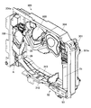
第2駆動力伝達部材615は、駆動力伝達歯車613に歯合する第1従動歯車615aと、第1従動歯車615aに歯合する第2従動歯車615b及び第3従動歯車615cと、第2従動歯車615bに歯合する第4従動歯車615dと、第3従動歯車615cに歯合する第5従動歯車615eと、第4従動歯車615dに歯合する第6従動歯車615fと、第6従動歯車615fに歯合する左側セクタ(扇形)歯車615gと、第5従動歯車615eに歯合する右側セクタ(扇形)歯車615hと、を備えている。そして、この第1従動歯車615a、第2従動歯車615b、第3従動歯車615c、第4従動歯車615d、及び第5従動歯車615eは、それぞれ駆動源取付ベース部材610の裏面に備えられたピンPに挿通された状態で止め金具Sにより挟着されて回転可能に支持されている。また、第2駆動力伝達部材615は、図5,7に示すように、駆動源取付ベース部材610の前面側に第2駆動モータ62による回転動力を伝達するクランク616と、このクランク616と、第2動作部としての胸部662と、を接続する第1連結部617と、このクランク616と、第3動作部としての腹部663と、を接続する第2連結部618と、を備えている。また、左側セクタ(扇形)歯車615g及び右側セクタ(扇形)歯車615hにはそれぞれトーションバネTの一端を固定することができるバネ固定部615g2,615h1が備えられており、トーションバネTの他端を駆動源取付ベース部材610に備えられたバネ固定部626に固定できるようになっている。   The second driving force transmission member 615 includes a first driven gear 615a that meshes with the driving force transmission gear 613, a second driven gear 615b and a third driven gear 615c that mesh with the first driven gear 615a, and a second driven gear. A fourth driven gear 615d meshed with the gear 615b, a fifth driven gear 615e meshed with the third driven gear 615c, a sixth driven gear 615f meshed with the fourth driven gear 615d, and a sixth driven gear 615f A left sector (sector-shaped) gear 615g that meshes with the second driven gear 615e, and a right sector (sector-shaped) gear 615h that meshes with the fifth driven gear 615e. The first driven gear 615a, the second driven gear 615b, the third driven gear 615c, the fourth driven gear 615d, and the fifth driven gear 615e are pins P provided on the back surface of the drive source mounting base member 610, respectively. In the state of being inserted through the metal plate, it is clamped by a stopper S and is rotatably supported. Further, as shown in FIGS. 5 and 7, the second driving force transmission member 615 includes a crank 616 that transmits rotational power from the second driving motor 62 to the front surface side of the driving source mounting base member 610, and the crank 616. A first connecting portion 617 that connects the chest portion 662 as the second operating portion, and a second connecting portion 618 that connects the crank 616 and the abdominal portion 663 as the third operating portion are provided. The left sector (sector-shaped) gear 615g and the right sector (sector-shaped) gear 615h are provided with spring fixing portions 615g2 and 615h1 that can fix one end of the torsion spring T, respectively. The drive source mounting base member 610 can be fixed to a spring fixing portion 626.

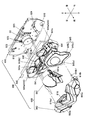
クランク616は、図7に示すように、左側セクタ歯車615gからの回転動力を伝達する左側クランク616aと、右側セクタ歯車615hからの回転動力を伝達する右側クランク616bと、を備えている。   As shown in FIG. 7, the crank 616 includes a left crank 616a that transmits rotational power from the left sector gear 615g and a right crank 616b that transmits rotational power from the right sector gear 615h.

左側クランク616aは、平板部材により構成され、この左側クランク616aの裏面側の一端には回転軸616a1が垂設されるとともに、その他端には、第2連結部618に係合する第2リンクピン616a3が垂設されている。また、この左側クランク616aの前面側には、第1連結部617aに係合する第1リンクピン616a2が垂設されている。なお、回転軸616a1の軸心と第1リンクピン616a2の軸心とを結ぶ線分の長さが、回転軸616a1の軸心と第2リンクピン616a3の軸心とを結ぶ線分の長さよりも短くなるように第1リンクピン616a2及び第2リンクピン616a3が設けられている。そして、回転軸616a1は、補助演出動作役物本体部640に設けられた貫通穴641、及び駆動源取付ベース部材610に設けられた貫通穴619を介して左側セクタ歯車615gに軸着されるようになっている。   The left crank 616a is formed of a flat plate member, and a rotating shaft 616a1 is vertically suspended at one end on the back side of the left crank 616a, and a second link pin that engages with the second connecting portion 618 at the other end. 616a3 is suspended. A first link pin 616a2 that engages with the first connecting portion 617a is suspended from the front side of the left crank 616a. The length of the line segment connecting the axis of the rotation shaft 616a1 and the axis of the first link pin 616a2 is longer than the length of the line segment connecting the axis of the rotation shaft 616a1 and the axis of the second link pin 616a3. The first link pin 616a2 and the second link pin 616a3 are provided so as to be shorter. The rotation shaft 616a1 is pivotally attached to the left sector gear 615g via a through hole 641 provided in the auxiliary effect operation accessory main body 640 and a through hole 619 provided in the drive source mounting base member 610. It has become.

右側クランク616bは、上述した左側クランク616aと左右対称に形成されており、左側クランク616aと同様に平板部材により構成されている。そして、この右側クランク616bの裏面側の一端には回転軸616b1が垂設されるとともに、その他端には、第2連結部618に係合する第2リンクピン616b3が垂設されている。また、この右側クランク616bの前面側には、第1連結部617bに係合する第1リンクピン616b2が垂設されている。なお、回転軸616b1の軸心と第1リンクピン616b2の軸心とを結ぶ線分の長さが、回転軸616b1の軸心と第2リンクピン616b3の軸心とを結ぶ線分の長さよりも短くなるように第1リンクピン616b2及び第2リンクピン616b3が設けられている。そして、回転軸616b1は、補助演出動作役物本体部640に設けられた貫通穴641、及び駆動源取付ベース部材610に設けられた貫通穴619を介して右側セクタ歯車615hに軸着されるようになっている。   The right crank 616b is formed to be bilaterally symmetric with the left crank 616a described above, and is formed of a flat plate member like the left crank 616a. A rotating shaft 616b1 is suspended from one end on the back side of the right crank 616b, and a second link pin 616b3 that engages with the second connecting portion 618 is suspended from the other end. Further, a first link pin 616b2 that engages with the first connecting portion 617b is suspended from the front side of the right crank 616b. The length of the line segment connecting the axis of the rotation shaft 616b1 and the axis of the first link pin 616b2 is longer than the length of the line segment connecting the axis of the rotation shaft 616b1 and the axis of the second link pin 616b3. The first link pin 616b2 and the second link pin 616b3 are provided so as to be shorter. The rotation shaft 616b1 is pivotally attached to the right sector gear 615h via a through hole 641 provided in the auxiliary effect operation accessory main body 640 and a through hole 619 provided in the drive source mounting base member 610. It has become.

第1連結部617は、図7に示すように、左側クランク616aに備えられた第1リンクピン616a2に係合する左側第1連結部617aと、右側クランク616bに備えられた第1リンクピン616b2に係合する右側第1連結部617bと、を備えている。   As shown in FIG. 7, the first connecting portion 617 includes a left first connecting portion 617a that engages with a first link pin 616a2 provided on the left crank 616a, and a first link pin 616b2 provided on the right crank 616b. Right-side first connecting portion 617b that engages with.

左側第1連結部617aは、平板部材により構成され、この左側第1連結部617aには、左右方向の右端に向けて傾斜する第1リンク孔617a1が設けられ、この第1リンク孔617a1の内壁を摺動可能であるとともに第1リンクピン616a2を軸着可能な軸受617a2を備えている。また、左側第1連結部617aの周縁には複数のネジ孔617a3,617a3,…が設けられており、この複数のネジ孔617a3,617a3,…を介して、胸部662の裏面に備えられたボス662b,662b,…にネジ止めされるようになっている。   The left first connecting portion 617a is formed of a flat plate member. The left first connecting portion 617a is provided with a first link hole 617a1 that is inclined toward the right end in the left-right direction, and an inner wall of the first link hole 617a1. And a bearing 617a2 on which the first link pin 616a2 can be mounted. Further, a plurality of screw holes 617a3, 617a3,... Are provided on the periphery of the left first connecting portion 617a, and a boss provided on the back surface of the chest 662 through the plurality of screw holes 617a3, 617a3,. 662b, 662b,... Are screwed.

右側第1連結部617bは、上述した左側第1連結部617aと左右対称に形成されており、左側第1連結部617aと同様に平板部材により構成されている。そして、この右側第1連結部617bには、左右方向の左端に向けて傾斜する第1リンク孔617b1が設けられ、この第1リンク孔617b1の内壁を摺動可能であるとともに第1リンクピン616b2を軸着可能な軸受617b2を備えている。また、右側第1連結部617bの周縁には複数のネジ孔617b3,617b3,…が設けられており、この複数のネジ孔617b3,617b3,…を介して、胸部662の裏面に備えられたボス662b,662b,…にネジ止めされるようになっている。   The right first connecting portion 617b is formed to be bilaterally symmetrical with the left first connecting portion 617a described above, and is formed of a flat plate member in the same manner as the left first connecting portion 617a. The right first connecting portion 617b is provided with a first link hole 617b1 which is inclined toward the left end in the left-right direction. The first link pin 616b2 can slide on the inner wall of the first link hole 617b1. Is provided with a bearing 617b2. Further, a plurality of screw holes 617b3, 617b3,... Are provided on the periphery of the right first connecting portion 617b, and the boss provided on the back surface of the chest 662 through the plurality of screw holes 617b3, 617b3,. 662b, 662b,... Are screwed.

第2連結部618は、略V字状の平板部材により構成され、この第2連結部618には、左右方向の左端から中央に向けて傾斜する第2リンク孔618a及び左右方向の右端から中央に向けて傾斜する第2リンク孔618bが設けられ、この第2リンク孔618aの内壁を摺動可能であるとともに第2リンクピン616a3を軸着可能な軸受618c及びこの第2リンク孔618bの内壁を摺動可能であるとともに第2リンクピン616b3を軸着可能な軸受618dを備えている。また、第2連結部618の下端部には複数のネジ孔618e,618e,…が設けられており、この複数のネジ孔618e,618e,…を介して、腹部663の裏面に備えられたボス663a,663a,…にネジ止めされるようになっている。また、図8(1)(2)に示すように、第2リンク孔618a及び第2リンク孔618bの長手方向の長さ(d2=42.63mm)は、第1リンク孔617a1及び第1リンク孔617b1の長手方向の長さ(d1=26.35mm)よりも長く設計されている。なお、左側第1連結部617a及び右側第1連結部617bは、上述のように、左右対称の部材であるため、図8(1)には、右側第1連結部617bのみを記載し、左側第1連結部617aについては省略した。   The second connecting portion 618 is formed of a substantially V-shaped flat plate member. The second connecting portion 618 includes a second link hole 618a that is inclined from the left end in the left-right direction toward the center and the center from the right end in the left-right direction. A second link hole 618b that is inclined toward the inner surface of the second link hole 618a. The bearing 618c is slidable on the inner wall of the second link hole 618a, and the second link pin 616a3 can be mounted on the shaft. And a bearing 618d capable of axially mounting the second link pin 616b3. In addition, a plurality of screw holes 618e, 618e,... Are provided at the lower end portion of the second connecting portion 618, and a boss provided on the back surface of the abdomen 663 through the plurality of screw holes 618e, 618e,. 663a, 663a,... Are screwed. Further, as shown in FIGS. 8A and 8B, the longitudinal lengths (d2 = 42.63 mm) of the second link hole 618a and the second link hole 618b are the same as the first link hole 617a1 and the first link. It is designed to be longer than the length (d1 = 26.35 mm) in the longitudinal direction of the hole 617b1. Since the left first connecting portion 617a and the right first connecting portion 617b are symmetrical members as described above, only the right first connecting portion 617b is shown in FIG. The first connecting part 617a is omitted.

また、駆動源取付ベース部材610裏面には、近接センサ621が備えられており、この近接センサ621は、左側セクタ(扇形)歯車615gに備えられた突出片615g1の有無を検知することで、補助演出動作役物600が可動したかどうかを検知することができるようになっている。また、駆動源取付ベース部材610裏面には、中継基板622が備えられており、第2駆動モータ62からの配線や補助演出動作部660に備えられた各LED基板144からの配線、近接センサ621からの配線を中継し、演出制御装置40に接続されるようになっている。   Also, a proximity sensor 621 is provided on the back surface of the drive source mounting base member 610, and this proximity sensor 621 detects the presence or absence of the protruding piece 615g1 provided in the left sector (sector-shaped) gear 615g, thereby assisting. It is possible to detect whether or not the production action object 600 has moved. In addition, a relay board 622 is provided on the rear surface of the drive source mounting base member 610, and wiring from the second drive motor 62, wiring from each LED board 144 provided in the auxiliary effect operation unit 660, and proximity sensor 621. Is connected to the production control device 40.

補助演出動作役物本体部640は、駆動源取付ベース部材610の前面に配置されるようになっており、回転軸616a1及び回転軸616b1を挿通する貫通穴641,641と、駆動源取付ベース部材610の前面に取り付けられた第2駆動モータ62及び顔部661に備えられた連結片661e,661eを挿通する開口部642と、補助演出動作役物本体部640の前面から裏面に向かって傾斜する傾斜面を有する突出部643と、LED発光部644,644と、装飾部材645と、を備えている。   The auxiliary effect operation accessory main body 640 is arranged on the front surface of the drive source mounting base member 610, and has through holes 641 and 641 through which the rotation shaft 616a1 and the rotation shaft 616b1 are inserted, and the drive source mounting base member. The second drive motor 62 attached to the front surface of 610 and the opening 642 through which the connecting pieces 661e and 661e provided on the face portion 661 are inserted, and the auxiliary effect operation accessory main body 640 are inclined from the front surface to the back surface. A protruding portion 643 having an inclined surface, LED light emitting portions 644 and 644, and a decorative member 645 are provided.

貫通穴641は、補助演出動作役物本体部640の右側下部及び左側下部に設けられており、補助演出動作役物本体部640の裏面側からは駆動源取付ベース部材610の前面に凸起した貫通穴619,619を挿通可能であるとともに、補助演出動作役物本体部640の前面側からは回転軸616a1及び回転軸616b1を挿通可能となっている。   The through holes 641 are provided at the lower right side and the lower left side of the auxiliary effect operation accessory main body 640, and protrude from the back side of the auxiliary effect operation accessory main body 640 to the front surface of the drive source mounting base member 610. The through holes 619 and 619 can be inserted, and the rotary shaft 616a1 and the rotary shaft 616b1 can be inserted from the front surface side of the auxiliary effect operation accessory body 640.

開口部642は、円柱形をなす第2駆動モータ62を挿通可能なように補助演出動作役物本体部640の略中央には円形の開口が形成されるとともに、この開口の両端には、連結片661e,661eが上下に往復運動可能な幅を有した矩形状の開口が形成されている。   The opening 642 is formed with a circular opening substantially at the center of the auxiliary effect operation accessory body 640 so that the cylindrical second drive motor 62 can be inserted, and both ends of the opening are connected to each other. A rectangular opening having a width that allows the pieces 661e and 661e to reciprocate up and down is formed.

突出部643は、顔部661の内面に備えられた当接ピン661bに当接する傾斜面を有する突出片643aと、この突出片643aが当接ピン661bに当接するように前後位置を調整した土台部643bと、を備えている。   The projecting portion 643 includes a projecting piece 643a having an inclined surface that abuts against the abutting pin 661b provided on the inner surface of the face 661, and a base whose front and rear position is adjusted such that the projecting piece 643a abuts on the abutting pin 661b. Part 643b.

突出片643aは、上端面が補助演出動作役物本体部640の前面側から裏面側に向けて傾斜した傾斜面を構成している。   The protruding piece 643a forms an inclined surface whose upper end surface is inclined from the front surface side to the back surface side of the auxiliary effect operation accessory main body 640.

土台部643bは、補助演出動作役物本体部640の前面に垂設された2本の脚部643b1,643b1と、この脚部643b1,643b1に架けられた載置部643b2とを備え、この載置部643b2に突出片643aが取り付けられるようになっている。   The base portion 643b includes two leg portions 643b1 and 643b1 suspended from the front surface of the auxiliary effect operation accessory main body 640, and a placement portion 643b2 spanned by the leg portions 643b1 and 643b1. The protruding piece 643a is attached to the mounting portion 643b2.

LED発光部644は、LED(図示省略)を備えたLED基板144と、LEDによる発光を透過させる透過部材644aと、を備えており、LED基板144は、補助演出動作役物本体部640の裏面側から、そして、透過部材644aはLED基板144に対向する位置に補助演出動作役物本体部640の前面側からそれぞれ取り付けられるようになっている。なお、このとき、LED基板144に繋がれる配線(図示省略)は、駆動源取付ベース部材610の前面上部に設けられた上溝623内に嵌入可能となっている。   The LED light emitting unit 644 includes an LED substrate 144 having LEDs (not shown) and a transmissive member 644a that transmits light emitted from the LEDs, and the LED substrate 144 is a back surface of the auxiliary effect operation accessory main body 640. From the side, the transmissive member 644a is attached to the position facing the LED board 144 from the front side of the auxiliary effect operation accessory main body 640, respectively. At this time, the wiring (not shown) connected to the LED substrate 144 can be fitted into an upper groove 623 provided in the upper front portion of the drive source mounting base member 610.

装飾部材645は、蓋部645aと、底部645bと、により構成され、この蓋部645aと、底部645bと、の間には、LED(図示省略)を備えたLED基板144が配設されている。そして、この蓋部645aの略中央にはLEDによる発光を透過させる透過部材645a1が備えられている。また、底部645bの裏面には、2つのボス(図示省略)が備えられており、補助演出動作役物本体部640の右側前面に備えられた2つの突起部645c,645cに嵌着されるようになっている。なお、この装飾部材645は、ロボットを演出する補助演出動作役物600のうちロボットが有する盾を演出するものである。   The decoration member 645 includes a lid portion 645a and a bottom portion 645b. Between the lid portion 645a and the bottom portion 645b, an LED substrate 144 having LEDs (not shown) is disposed. . A transmissive member 645a1 that transmits light emitted from the LED is provided in the approximate center of the lid 645a. In addition, two bosses (not shown) are provided on the back surface of the bottom portion 645b, and are fitted to the two protrusions 645c and 645c provided on the right front surface of the auxiliary effect operation accessory main body 640. It has become. In addition, this decoration member 645 produces | generates the shield which a robot has among the auxiliary | assistance production | presentation action objects 600 which produce a robot.

補助演出動作部660は、補助演出動作役物本体部640の前面に配置されるようになっており、第1動作部としての顔部661と、第2動作部としての胸部662と、第3動作部としての腹部663と、を備えている。   The auxiliary effect operation unit 660 is arranged in front of the auxiliary effect operation accessory body 640, and includes a face 661 as a first operation unit, a chest 662 as a second operation unit, and a third unit. And an abdominal part 663 as an operation part.

顔部661は、ロボットを演出する補助演出動作役物600のうちロボットの顔を演出する部材で構成され、顔部661のうち目を演出する箇所(例えば、図13参照)にはLEDによる発光を透過させる透過部材661aが備えられ、顔部661の裏面には、透過部材661aに対向する位置にLED基板144が配置されるようになっている。なお、顔部661が補助演出動作役物本体部640を介して駆動源取付ベース部材610に取り付けられたとき、顔部661の裏面に備えられたLED基板144に繋がれる配線(図示省略)は、駆動源取付ベース部材610の前面下部に設けられた下溝624内に嵌入可能となっている。   The face part 661 is composed of a member that produces the face of the robot in the auxiliary effect operation accessory 600 that produces the robot, and the LED part emits light to a part (for example, see FIG. 13) that produces the eyes of the face part 661. The LED board 144 is arranged on the back surface of the face portion 661 at a position facing the transmission member 661a. In addition, when the face part 661 is attached to the drive source attachment base member 610 via the auxiliary effect operation accessory main body part 640, wiring (not shown) connected to the LED substrate 144 provided on the back surface of the face part 661 is provided. The drive source mounting base member 610 can be fitted into a lower groove 624 provided at the lower front surface.

また、図15に示すように、顔部661の裏面上部には、突出片643aに当接する当接ピン661bを備えるとともに、顔部661の裏面下部には、引張バネ661cを備えている。この当接ピン661bは、軸方向が顔部661の左右方向に一致するように配設されている。また、引張バネ661cは、その一端に備えられたフックが顔部661の裏面下部に係合されるとともに、その他端に備えられたフックは補助演出動作役物本体部640に係合されるようになっている。   Further, as shown in FIG. 15, an upper surface of the back surface of the face portion 661 includes a contact pin 661 b that contacts the protruding piece 643 a, and a lower surface of the back surface of the face portion 661 includes a tension spring 661 c. The contact pin 661b is disposed so that the axial direction thereof coincides with the left-right direction of the face portion 661. Further, the tension spring 661c has a hook provided at one end thereof engaged with a lower part of the back surface of the face 661, and a hook provided at the other end is engaged with the auxiliary effect operation accessory body 640. It has become.

また、顔部661の左右両端部には、それぞれ顔部661を回動させるための回動軸部661dを備え、この回動軸部661dに連結片661eが連結されている。そして、この回動軸部661dは、軸方向が顔部661の左右方向に一致するように配設されている。   The left and right ends of the face portion 661 are provided with turning shaft portions 661d for turning the face portion 661, and a connecting piece 661e is connected to the turning shaft portion 661d. The rotation shaft portion 661d is disposed such that the axial direction coincides with the left-right direction of the face portion 661.

胸部662は、ロボットを演出する補助演出動作役物600のうちロボットの胸を演出する部材で構成され、この胸部662の左右両端にはLEDによる発光を透過させる透過部材662aが備えられ、胸部662の裏面には、透過部材662aに対向する位置にLED基板144が配置されるようになっている。   The chest 662 is composed of a member that produces the chest of the robot in the auxiliary production operation accessory 600 that produces the robot. The chest 662 is provided with a transmissive member 662a that transmits light emitted from the LEDs at both left and right ends. On the back surface of the LED board 144, an LED substrate 144 is arranged at a position facing the transmission member 662a.

また、胸部662の裏面には、上述したように、左側第1連結部617a及び右側第1連結部617bを取り付けるための複数のボス662b,662b,…が所定の位置に配設されている。さらに、胸部662の裏面には、腹部663の可動をガイドするガイド部材662cを備えており、ガイド部材662cもまたボス662b,662b,…にネジ止めされるようになっている。   Further, as described above, a plurality of bosses 662b, 662b,... For attaching the left first connecting portion 617a and the right first connecting portion 617b are disposed at predetermined positions on the back surface of the chest 662. Further, a guide member 662c for guiding the movement of the abdomen 663 is provided on the back surface of the chest 662, and the guide member 662c is also screwed to the bosses 662b, 662b,.

ガイド部材662cは、略矩形状の平板部材で構成されており、その左右両端部には、リンク孔662c1,662c1を備えるとともに、その中央には、スリット662c2を備えている。   The guide member 662c is formed of a substantially rectangular flat plate member. The guide member 662c includes link holes 662c1 and 662c1 at both left and right ends thereof, and a slit 662c2 at the center thereof.

リンク孔662c1は、縦長の長孔により構成されており、リンク孔662c1の内壁を摺動可能な軸受662c3を備えている。そして、この軸受662c3は、後述する腹部663に備えられたリンクピン663bを軸着可能となっている。   The link hole 662c1 is formed by a vertically long slot, and includes a bearing 662c3 that can slide on the inner wall of the link hole 662c1. And this bearing 662c3 can axially mount the link pin 663b with which the abdominal part 663 mentioned later is equipped.

スリット662c2は、縦長の短冊状の長孔により構成されており、このスリット662c2内に後述する腹部663の前面に備えられた突出片663cが挿通可能となっている。   The slit 662c2 is configured by a vertically long strip-shaped long hole, and a protruding piece 663c provided on the front surface of the abdomen 663 described later can be inserted into the slit 662c2.

腹部663は、ロボットを演出する補助演出動作役物600のうちロボットの腹を演出する部材で構成され、補助演出動作役物本体部640の前面側、かつ、胸部の裏面側に配置されるようになっている。この腹部663の裏面には、上述したように、第2連結部618を取り付けるための複数のボス663a,663a,…が所定の位置に配設されている。また、腹部663の左右両端部には、それぞれ、腹部663の前面側に向かってリンクピン663bが垂設され。このリンクピン663bは、軸受662c3に軸着されるようになっている。また、腹部663の中央部には、腹部663の前面側に向かって突出片663cが垂説され、この突出片663cは、スリット662c2に挿通されるようになっている。   The abdomen 663 is composed of a member that produces the robot's belly among the auxiliary effecting action objects 600 that produce the robot, and is arranged on the front side of the auxiliary effecting action body main part 640 and on the back side of the chest. It has become. As described above, a plurality of bosses 663a, 663a,... For attaching the second connecting portion 618 are disposed on the back surface of the abdomen 663 at predetermined positions. In addition, link pins 663b are vertically provided at both left and right ends of the abdomen 663 toward the front side of the abdomen 663. The link pin 663b is pivotally attached to the bearing 662c3. Further, a projecting piece 663c is drawn in the center of the abdomen 663 toward the front side of the abdomen 663, and the projecting piece 663c is inserted through the slit 662c2.

次に、図9〜15に示すように、補助演出動作役物600の演出動作について説明する。   Next, as shown in FIGS. 9 to 15, an effect operation of the auxiliary effect operation accessory 600 will be described.

まず、図9に示すように、表示装置41において変動表示ゲームが行われており、左図柄、右図柄、中図柄の識別情報が変動中の場合、補助演出動作役物600は、通常状態(演出動作前)にある。具体的には、図10(1)に示すように、第2駆動モータ62の駆動軸62aを軸着した駆動力伝達歯車613は、初期位置に配置され、この駆動力伝達歯車613のアーム613bに備えられたピン613cの位置は、変換部材614aに形成されたガイド孔614bの駆動源取付ベース部材610の裏面側から見て左側端に位置した状態となっている。従って、この段階では、ピン613cが変換部材614aを押圧していないので、補助演出動作部660を構成する顔部661も通常状態(図15(1)参照)にある。また、このとき、左側セクタ歯車615gに備えられた突出片615g1は、近接センサ621に対向する位置に配設されており、これにより、補助演出動作役物600が通常状態(演出動作前)にあることを検知することができるようになっている。また、図10(2)に示すように、通常状態(演出動作前)では、補助演出動作部660を構成する胸部662及び腹部663は前後に重なり合った状態で基準位置Bの高さに配置されている。   First, as shown in FIG. 9, when the variable display game is performed on the display device 41 and the identification information of the left symbol, the right symbol, and the middle symbol is fluctuating, the auxiliary effect action actor 600 is in a normal state ( It is in the stage before the production operation. Specifically, as shown in FIG. 10 (1), the driving force transmission gear 613 that is attached to the driving shaft 62a of the second driving motor 62 is disposed at the initial position, and the arm 613b of the driving force transmission gear 613 is disposed. The position of the pin 613c provided in the guide member 614a is located at the left end when viewed from the back side of the drive source mounting base member 610 of the guide hole 614b formed in the conversion member 614a. Therefore, at this stage, since the pin 613c does not press the conversion member 614a, the face 661 constituting the auxiliary effect operation unit 660 is also in the normal state (see FIG. 15 (1)). Further, at this time, the protruding piece 615g1 provided in the left sector gear 615g is disposed at a position facing the proximity sensor 621, so that the auxiliary effect operation accessory 600 is in a normal state (before the effect operation). It can be detected. As shown in FIG. 10 (2), in the normal state (before the production operation), the chest 662 and the abdomen 663 constituting the auxiliary production operation unit 660 are arranged at the height of the reference position B in a state where they overlap each other. ing.

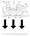
次いで、図11に示すように、例えば、表示装置41において実行されている変動表示ゲームがリーチ状態となった場合、補助演出動作役物600の胸部662及び腹部663が駆動し、表示装置41の前面を覆う位置に移動する(第1段階)。具体的には、図12(1)に示すように、第2駆動モータ62の駆動軸62aを軸着した駆動力伝達歯車613は、第2駆動モータ62の駆動によって、駆動源取付ベース部材610の裏面側から見て時計回りに回動を開始する。そして、このとき、駆動力伝達歯車613のアーム613bに備えられたピン613cの位置は、変換部材614aに形成された円弧状のガイド孔614bの略中央に位置した状態となっている。従って、この段階では、ピン613cが変換部材614aを押圧していないので、補助演出動作部660を構成する顔部661は通常状態(図15(1)参照)にある。また、このとき、駆動力伝達歯車613の回動に従動して左側セクタ歯車615g及び右側セクタ歯車615hも回動し、左側セクタ歯車615g及び右側セクタ歯車615hに軸着された回転軸616a1及び回転軸616b1も回転することとなる。これにより、図12(2)に示すように、左側クランク616aは補助演出動作部660の裏面側から見て反時計回りに回動するとともに右側クランク616bは補助演出動作部660の裏面側から見て時計回りに回動する。そして、このとき、左側クランク616aに備えられた第1リンクピン616a2及び第2リンクピン616a3は、それぞれ第1リンク孔617a1及び第2リンク孔618aを押圧しながら、第1リンク孔617a1及び第2リンク孔618aそれぞれの内壁を摺動する。そして、第1リンクピン616a2及び第2リンクピン616a3によって押圧された第1リンク孔617a1を備える左側第1連結部617a及び第2リンク孔618aを備える第2連結部618は下方に可動する。また、同様に、右側クランク616bに備えられた第1リンクピン616b2及び第2リンクピン616b3は、それぞれ第1リンク孔617b1及び第2リンク孔618bを押圧しながら、第1リンク孔617b1及び第2リンク孔618bそれぞれの内壁を摺動する。そして、第1リンクピン616b2及び第2リンクピン616b3によって押圧された第1リンク孔617b1を備える右側第1連結部617b及び第2リンク孔618bを備える第2連結部618は下方に可動する。そして、左側第1連結部617a及び右側第1連結部617bに接続された胸部662は、基準位置Cの高さに配置され、第2連結部618に接続された腹部663は、基準位置CとDの中間位置の高さに配置される。   Next, as shown in FIG. 11, for example, when the variable display game being executed on the display device 41 is in the reach state, the chest 662 and the abdomen 663 of the auxiliary effect operation accessory 600 are driven, and the display device 41 Move to a position covering the front (first stage). Specifically, as shown in FIG. 12 (1), the drive force transmission gear 613 that is attached to the drive shaft 62 a of the second drive motor 62 is driven by the second drive motor 62 so that the drive source mounting base member 610 is driven. Starts turning clockwise as seen from the back side. At this time, the position of the pin 613c provided in the arm 613b of the driving force transmission gear 613 is in a state of being located at the approximate center of the arcuate guide hole 614b formed in the conversion member 614a. Accordingly, at this stage, since the pin 613c does not press the conversion member 614a, the face 661 constituting the auxiliary effect operation unit 660 is in a normal state (see FIG. 15 (1)). At this time, the left sector gear 615g and the right sector gear 615h are also rotated in accordance with the rotation of the driving force transmission gear 613, and the rotation shaft 616a1 and the rotation shaft that are pivotally attached to the left sector gear 615g and the right sector gear 615h. The shaft 616b1 also rotates. Accordingly, as shown in FIG. 12 (2), the left crank 616a rotates counterclockwise when viewed from the back side of the auxiliary effect operating unit 660 and the right crank 616b is viewed from the back side of the auxiliary effect operating unit 660. Turn clockwise. At this time, the first link pin 616a2 and the second link pin 616a3 provided on the left crank 616a press the first link hole 617a1 and the second link hole 618a, respectively, and the first link hole 617a1 and the second link pin 616a3. The inner wall of each link hole 618a slides. The left first connecting portion 617a including the first link hole 617a1 pressed by the first link pin 616a2 and the second link pin 616a3 and the second connecting portion 618 including the second link hole 618a move downward. Similarly, the first link pin 616b2 and the second link pin 616b3 provided in the right crank 616b press the first link hole 617b1 and the second link hole 618b, respectively, and the first link hole 617b1 and the second link pin 616b3. The inner wall of each link hole 618b slides. The right first connecting portion 617b including the first link hole 617b1 and the second connecting portion 618 including the second link hole 618b pressed by the first link pin 616b2 and the second link pin 616b3 move downward. The chest 662 connected to the left first connecting part 617a and the right first connecting part 617b is arranged at the height of the reference position C, and the abdomen 663 connected to the second connecting part 618 is connected to the reference position C. It is arranged at the height of the middle position of D.

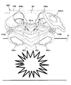
次いで、図13に示すように、補助演出動作役物600の胸部662が最下点まで可動した後も時間差を設けて腹部663がさらに駆動し、表示装置41の前面を覆う位置に移動する(第2段階)。そして、このとき、表示装置41には、補助演出動作役物600の顔部661、胸部662、腹部663に関連した脚部Fが表示され、補助演出動作役物600と、表示装置41における演出との融合により、ロボットの役物が姿を現すという特定の演出を実行可能となっている。具体的には、図14(1)に示すように、第2駆動モータ62の駆動軸62aを軸着した駆動力伝達歯車613は、第2駆動モータ62の駆動によって、駆動源取付ベース部材610の裏面側から見て時計回りに回動を継続する。そして、このとき、駆動力伝達歯車613のアーム613bに備えられたピン613cの位置は、変換部材614aに形成されたガイド孔614bの駆動源取付ベース部材610の裏面側から見て右側端に位置した状態となっている。従って、このとき、ピン613cが変換部材614aを下方に押圧する力が発生する。これにより、変換部材614aは押下げられ、この変換部材614aに接続された顔部661も押下げられ、顔部661の裏面に備えられた当接ピン661bは、補助演出動作役物本体部640に備えられた突出片643aに当接するとともに、突出片643aの上面を摺動することにより、顔部661は回動軸部661dを中心として回転し、顔部661の下端部(ロボットの顎の部分)が前面側に突き出るような動作(図15(2)参照)を行う。なお、顔部661の下端部の裏面には引張バネ661cが備えられているため、この引張バネ661cの付勢により、好適に顔部661の位置を元に戻すことが可能となっている。   Next, as shown in FIG. 13, the abdomen 663 is further driven with a time lag even after the chest 662 of the auxiliary effect operation accessory 600 moves to the lowest point, and moves to a position covering the front surface of the display device 41 ( Second stage). At this time, the display device 41 displays the legs F related to the face 661, the chest 662, and the abdomen 663 of the auxiliary effect operation accessory 600, and the effect on the auxiliary effect operation accessory 600 and the display device 41 is displayed. With the integration, it is possible to carry out a specific production in which the role of the robot appears. Specifically, as shown in FIG. 14 (1), the drive force transmission gear 613 that is attached to the drive shaft 62 a of the second drive motor 62 is driven by the second drive motor 62 to drive source mounting base member 610. Continue to rotate clockwise as seen from the back side. At this time, the position of the pin 613c provided in the arm 613b of the driving force transmission gear 613 is positioned at the right end when viewed from the back side of the driving source mounting base member 610 of the guide hole 614b formed in the conversion member 614a. It has become a state. Accordingly, at this time, a force that the pin 613c presses the conversion member 614a downward is generated. As a result, the conversion member 614a is pushed down, the face portion 661 connected to the conversion member 614a is also pushed down, and the abutment pin 661b provided on the back surface of the face portion 661 is an auxiliary effect operation accessory main body 640. The face portion 661 rotates about the rotation shaft portion 661d and slides on the upper surface of the protrusion piece 643a, and the lower end portion of the face portion 661 (the jaw of the robot) An operation (see FIG. 15 (2)) is performed so that the portion) protrudes to the front side. In addition, since the tension spring 661c is provided in the back surface of the lower end part of the face part 661, the position of the face part 661 can be suitably returned to the original position by urging | biasing this tension spring 661c.

また、このとき、駆動力伝達歯車613の回動に従動して左側セクタ歯車615g及び右側セクタ歯車615hも回動し、左側セクタ歯車615g及び右側セクタ歯車615hに軸着された回転軸616a1及び回転軸616b1も回転することとなる。これにより、図14(2)に示すように、左側クランク616aは補助演出動作部660の裏面側から見て反時計回りに回動するとともに右側クランク616bは補助演出動作部660の裏面側から見て時計回りに回動する。そして、このとき、左側クランク616aに備えられた第1リンクピン616a2及び第2リンクピン616a3は、それぞれ第1リンク孔617a1及び第2リンク孔618aを押圧しながら、第1リンク孔617a1及び第2リンク孔618aそれぞれの内壁を摺動する。そして、このとき、第2リンク孔618aの長手方向の長さが第1リンク孔617a1の長手方向の長さよりも長いため、第1リンクピン616a2が第1リンク孔617a1の一端から他端まで摺動し終わった後でも、第2リンクピン616a3は、さらに、第2リンク孔618aの内壁を摺動可能となっている。また、同様に、第2リンク孔618bの長手方向の長さが第1リンク孔617b1の長手方向の長さよりも長いため、第1リンクピン616b2が第1リンク孔617b1の一端から他端まで摺動し終わった後でも、第2リンクピン616b3は、さらに、第2リンク孔618bの内壁を摺動可能となっている。これにより、左側第1連結部617a及び右側第1連結部617bに接続された胸部662は、最下点である基準位置CとDの中間位置に可動した後も、第2連結部618に接続された腹部663は、さらに基準位置Dの高さまで可動することとなる。   At this time, the left sector gear 615g and the right sector gear 615h are also rotated in accordance with the rotation of the driving force transmission gear 613, and the rotation shaft 616a1 and the rotation shaft that are pivotally attached to the left sector gear 615g and the right sector gear 615h. The shaft 616b1 also rotates. Accordingly, as shown in FIG. 14 (2), the left crank 616a rotates counterclockwise when viewed from the back side of the auxiliary effect operating unit 660 and the right crank 616b is viewed from the back side of the auxiliary effect operating unit 660. Turn clockwise. At this time, the first link pin 616a2 and the second link pin 616a3 provided on the left crank 616a press the first link hole 617a1 and the second link hole 618a, respectively, and the first link hole 617a1 and the second link pin 616a3. The inner wall of each link hole 618a slides. At this time, since the length in the longitudinal direction of the second link hole 618a is longer than the length in the longitudinal direction of the first link hole 617a1, the first link pin 616a2 slides from one end to the other end of the first link hole 617a1. Even after the movement is completed, the second link pin 616a3 can slide on the inner wall of the second link hole 618a. Similarly, since the length of the second link hole 618b in the longitudinal direction is longer than the length of the first link hole 617b1, the first link pin 616b2 slides from one end of the first link hole 617b1 to the other end. Even after the movement is completed, the second link pin 616b3 can slide on the inner wall of the second link hole 618b. Accordingly, the chest 662 connected to the left first connecting portion 617a and the right first connecting portion 617b is connected to the second connecting portion 618 even after moving to the intermediate position between the reference positions C and D, which is the lowest point. The abdomen 663 thus moved further to the height of the reference position D.

以上のように、所定の演出動作を行う補助演出動作役物600と、補助演出動作役物600の演出動作を制御する演出制御手段(演出制御装置40)と、を備えたパチンコ遊技機100において、補助演出動作役物600は、補助演出動作部660と、補助演出動作部660を駆動させる駆動源(第2駆動モータ62)と、駆動源を取り付けるための駆動源取付ベース部材610と、を備え、補助演出動作部660は、第1動作部(顔部661)と、第2動作部(胸部662)と、第3動作部(腹部663)と、を備え、駆動源取付ベース部材610は、駆動源の駆動力を第1動作部に伝達する第1駆動力伝達部材614と、駆動源の駆動力を第2動作部及び第3動作部に伝達する第2駆動力伝達部材615と、を備え、駆動源が駆動して第2駆動力伝達部材へ駆動力を伝達させることによって、第2動作部及び第3動作部の動作を開始させ、該第2動作部及び第3動作部の動作開始後、第2駆動力伝達部材へ伝達させる駆動力を第1駆動力伝達部材へも伝達させることによって、第1動作部の動作を開始させることとなる。   As described above, in the pachinko gaming machine 100 that includes the auxiliary effect operation accessory 600 that performs a predetermined effect operation, and the effect control means (the effect control device 40) that controls the effect operation of the auxiliary effect operation accessory 600. The auxiliary effect operation accessory 600 includes an auxiliary effect operation unit 660, a drive source (second drive motor 62) for driving the auxiliary effect operation unit 660, and a drive source attachment base member 610 for attaching the drive source. The auxiliary effect operation unit 660 includes a first operation unit (face unit 661), a second operation unit (chest unit 662), and a third operation unit (abdomen 663), and the drive source mounting base member 610 includes A first driving force transmission member 614 that transmits the driving force of the driving source to the first operating portion; a second driving force transmission member 615 that transmits the driving force of the driving source to the second operating portion and the third operating portion; The drive source is driven first By transmitting the driving force to the driving force transmission member, the operation of the second operation unit and the third operation unit is started, and after the operation of the second operation unit and the third operation unit is started, to the second driving force transmission member By transmitting the driving force to be transmitted also to the first driving force transmission member, the operation of the first operation unit is started.

従って、第2駆動力伝達部材615によって、駆動源(第2駆動モータ62)の駆動力を第2動作部(胸部662)と第3動作部(腹部663)とに伝達することができるとともに、この伝達により第2動作部(胸部662)と第3動作部(腹部663)との動作が開始した後、第2駆動力伝達部材615へ伝達させる駆動力を第1駆動力伝達部材614へも伝達させることによって、第1動作部(顔部661)の動作を開始させることができるので、各動作部毎に伝達部材を備える必要がなくなり、複数の動作部(可動部材)をそれぞれ効率良く構成するとともに伝達部材の数が増えることによるコストを削減でき、また、斬新な演出動作を行わせることができるようになる。   Therefore, the second driving force transmitting member 615 can transmit the driving force of the driving source (second driving motor 62) to the second operating portion (chest 662) and the third operating portion (abdominal 663), and After the operation of the second operation unit (chest 662) and the third operation unit (abdomen 663) is started by this transmission, the driving force transmitted to the second driving force transmission member 615 is also applied to the first driving force transmission member 614. By transmitting, the operation of the first operation unit (face unit 661) can be started, so there is no need to provide a transmission member for each operation unit, and each of the plurality of operation units (movable members) is configured efficiently. In addition, the cost due to the increase in the number of transmission members can be reduced, and a novel presentation operation can be performed.

また、第2駆動力伝達部材615は、駆動源(第2駆動モータ62)による回転動力を伝達するクランク616と、クランク616と、第2動作部(胸部662)と、を接続する第1連結部617と、クランク616と、第3動作部(腹部663)と、を接続する第2連結部618と、を備え、第1連結部は、長孔状の第1リンク孔617a1,617b1を備え、第2連結部618は、第1リンク孔617a1,617b1の長手方向の長さよりも長い長孔を有する第2リンク孔618a,618bを備え、クランク616は、第1リンク孔617a1,617b1に係合するとともに当該第1リンク孔617a1,617b1を摺動する第1リンクピン616a2,616b2と、第2リンク孔618a,618bに係合するとともに当該第2リンク孔618a,618bを摺動する第2リンクピン616a3,616b3と、を備えたこととなる。   The second driving force transmission member 615 has a first connection that connects the crank 616 that transmits rotational power from the driving source (second driving motor 62), the crank 616, and the second operating portion (chest 662). A second connecting portion 618 that connects the portion 617, the crank 616, and the third operating portion (abdomen 663), and the first connecting portion includes first link holes 617a1 and 617b1 each having a long hole shape. The second connecting portion 618 includes second link holes 618a and 618b having elongated holes longer than the lengths of the first link holes 617a1 and 617b1, and the crank 616 is engaged with the first link holes 617a1 and 617b1. Are engaged with the first link pins 616a2 and 616b2 that slide in the first link holes 617a1 and 617b1 and the second link holes 618a and 618b. The second link hole 618a, and the second link pin 616a3,616b3 which slides 618b, and thus having a.

これにより、駆動源(第2駆動モータ62)による回転動力によってクランク616が回転した際、該クランク616に備えられた第1リンクピン616a2,616b2及び第2リンクピン616a3,616b3に摺動されて第1リンク孔617a1,617b1を備える第1連結部617及び第2リンク孔618a,618bを備える第2連結部618が可動することとなる。また、第2リンク孔618a,618bは、第1リンク孔617a1,617b1の長手方向の長さよりも長い長孔を有するので、第1連結部617が可動し終わっても、第2連結部618はさらに、可動を続けることとなる。
従って、第2駆動力伝達部材615によって駆動源(第2駆動モータ62)の駆動力を第2動作部(胸部662)と第3動作部(腹部663)とに伝達することによって、第2動作部と第3動作部とを可動させ、さらに第3動作部だけを可動させることができることとなり、補助演出動作役物600によって斬新な演出効果を奏することができるようになる。
As a result, when the crank 616 is rotated by the rotational power from the drive source (second drive motor 62), the crank 616 is slid by the first link pins 616a2 and 616b2 and the second link pins 616a3 and 616b3 provided on the crank 616. The 1st connection part 617 provided with the 1st link holes 617a1 and 617b1 and the 2nd connection part 618 provided with the 2nd link holes 618a and 618b will move. Further, since the second link holes 618a and 618b have long holes longer than the lengths of the first link holes 617a1 and 617b1 in the longitudinal direction, even if the first connection part 617 finishes moving, the second connection part 618 Furthermore, it will continue to move.
Therefore, the second driving force transmitting member 615 transmits the driving force of the driving source (second driving motor 62) to the second operating part (chest part 662) and the third operating part (abdominal part 663), whereby the second action. The third and third operating parts can be moved, and only the third operating part can be moved, and the auxiliary effect operating accessory 600 can provide a novel effect.

また、補助演出動作役物600は、補助演出動作部660が設けられる補助演出動作役物本体部640を備え、第1駆動力伝達部材614は、駆動源(第2駆動モータ62)による回転動力を伝達するアーム613bと、当該アーム613bと、第1動作部(顔部661)と、を接続するとともにアーム613bによる回転運動を直線運動に変換する変換部材614aと、を備え、補助演出動作役物本体部640は、変換部材614aに接続された第1動作部が直線運動する方向に対して所定の角度をなす傾斜面を有する突出片643aを備え、第1動作部は、傾斜面に当接する当接ピン661bと、当該第1動作部を回動させる回動軸部661dと、この回動軸部661dと、変換部材614aと、を接続する連結片661eと、を備え、当接ピン661bは、第1動作部が直線運動した際、突出片643aの傾斜面に当接することとなる。   Further, the auxiliary effect operation accessory 600 includes an auxiliary effect operation accessory main body 640 provided with an auxiliary effect operation part 660, and the first driving force transmission member 614 is rotational power by a drive source (second drive motor 62). And a conversion member 614a that connects the arm 613b to the first motion part (face part 661) and converts the rotational motion by the arm 613b to linear motion, The object main body 640 includes a protruding piece 643a having an inclined surface that forms a predetermined angle with respect to a direction in which the first operating unit connected to the conversion member 614a linearly moves, and the first operating unit contacts the inclined surface. A contact pin 661b that comes into contact; a rotation shaft portion 661d that rotates the first operation portion; a connection piece 661e that connects the rotation shaft portion 661d and the conversion member 614a; Contact pin 661b is when the first operation portion is linear movement, and abuts against the inclined surface of the projecting piece 643a.

従って、駆動源(第2駆動モータ62)の駆動力によって、第1動作部(顔部661)は直線運動を行うだけではなく、補助演出動作役物本体部640に備えられた突出片643aの傾斜面に沿っても運動するので、第1動作部は回動軸部661dを中心として回動することとなり、補助演出動作役物600によって、より斬新な演出効果を奏することができるようになる。   Accordingly, the first operating part (face part 661) not only performs a linear motion by the driving force of the driving source (second driving motor 62), but also the protruding piece 643a provided in the auxiliary effect operating accessory body part 640. Since it also moves along the inclined surface, the first operation part rotates about the rotation shaft part 661d, and the auxiliary effect operation accessory 600 can provide a more novel effect. .

また、当該パチンコ遊技機100は、複数の識別情報を変動表示する変動表示ゲームを表示画面にて実行する表示装置41を備え、演出制御手段(演出制御装置40)は、表示装置41の表示制御を行うとともに、表示装置41において実行される変動表示ゲームに基づいて補助演出動作役物600による所定の演出動作の制御を行い、補助演出動作役物600が所定の演出動作を行った場合に、表示画面に特定の演出表示をさせたこととなる。   In addition, the pachinko gaming machine 100 includes a display device 41 that executes a variable display game that displays a plurality of identification information in a variable manner on a display screen, and the effect control means (effect control device 40) controls display of the display device 41. And performing control of a predetermined effect operation by the auxiliary effect operation accessory 600 based on the variable display game executed on the display device 41, and when the auxiliary effect operation accessory 600 performs a predetermined effect operation, This means that a specific effect display is made on the display screen.

従って、演出制御手段(演出制御装置40)によって、表示装置41の表示制御を行うとともに、表示装置41において実行される変動表示ゲームに基づいて補助演出動作役物600による所定の演出動作の制御を行い、補助演出動作役物600が所定の演出動作を行った場合に、表示画面に特定の演出表示をさせることができるので、表示装置41における演出表示と補助演出動作役物600における演出が融合した従来にない斬新な演出を実現することができるようになる。   Therefore, the display control of the display device 41 is performed by the effect control means (the effect control device 40), and a predetermined effect operation control by the auxiliary effect operation accessory 600 is performed based on the variable display game executed on the display device 41. When the auxiliary effect operation accessory 600 performs a predetermined effect operation, a specific effect display can be displayed on the display screen, so that the effect display on the display device 41 and the effect in the auxiliary effect operation accessory 600 are merged. It will be possible to realize a novel production that has never been achieved before.

なお、今回開示された実施の形態はすべての点で例示であって制限的なものではないと考えられるべきである。本発明の範囲は上記した説明ではなくて特許請求の範囲によって示され、特許請求の範囲と均等の意味および範囲内でのすべての変更が含まれることが意図される。   The embodiment disclosed this time should be considered as illustrative in all points and not restrictive. The scope of the present invention is defined by the terms of the claims, rather than the description above, and is intended to include any modifications within the scope and meaning equivalent to the terms of the claims.

例えば、本実施例において、補助演出動作部は、第1動作部、第2動作部、第3動作部と、を備える構成としたが、これに限らず、3つ以上の動作部を備える構成としても良い。   For example, in the present embodiment, the auxiliary performance operation unit includes the first operation unit, the second operation unit, and the third operation unit. However, the configuration is not limited thereto, and includes three or more operation units. It is also good.

本発明を適用した一実施の形態の構成を示すパチンコ遊技機における遊技盤の正面図である。1 is a front view of a game board in a pachinko gaming machine showing a configuration of an embodiment to which the present invention is applied. 本発明を適用した一実施の形態の構成を示すパチンコ遊技機の制御系の一部を示すブロック図である。It is a block diagram which shows a part of control system of the pachinko game machine which shows the structure of one embodiment to which the present invention is applied. センターケースを構成する前面構成部材を示す斜視図である。It is a perspective view which shows the front structural member which comprises a center case. センターケースを構成する後面構成部材を示す斜視図である。It is a perspective view which shows the rear surface structural member which comprises a center case. 補助演出動作役物の前面側から見た分解斜視図である。FIG. 駆動源取付ベース部材の裏面側から見た分解斜視図である。It is the disassembled perspective view seen from the back surface side of the drive source attachment base member. 補助演出動作部の裏面側から見た分解斜視図である。It is the disassembled perspective view seen from the back side of the auxiliary production operation part. (1)第1連結部(右側第1連結部)を示す背面図、(2)第2連結部を示す背面図である。(1) It is a rear view which shows a 1st connection part (right side 1st connection part), (2) It is a rear view which shows a 2nd connection part. 補助演出動作役物における演出動作および変動表示装置における表示の一例を示す図である。It is a figure which shows an example of the display in the production | presentation operation | movement and auxiliary | assistant display device in an auxiliary production operation | working object. (1)図9における演出動作時の駆動源取付ベース部材の背面図、(2)図9における演出動作時の補助演出動作部の背面図である。(1) A rear view of the drive source mounting base member during the rendering operation in FIG. 9, and (2) a rear view of the auxiliary rendering operation unit during the rendering operation in FIG. 補助演出動作役物における演出動作および変動表示装置における表示の一例を示す図である。It is a figure which shows an example of the display in the production | presentation operation | movement and auxiliary | assistant display device in an auxiliary production operation | working object. (1)図11における演出動作時の駆動源取付ベース部材の背面図、(2)図11における演出動作時の補助演出動作部の背面図である。(1) The rear view of the drive source attachment base member at the time of the production | presentation operation | movement in FIG. 補助演出動作役物における演出動作および変動表示装置における表示の一例を示す図である。It is a figure which shows an example of the display in the production | presentation operation | movement and auxiliary | assistant display device in an auxiliary production operation | working object. (1)図13における演出動作時の駆動源取付ベース部材の背面図、(2)図13における演出動作時の補助演出動作部の背面図である。(1) FIG. 14 is a rear view of the drive source mounting base member during the rendering operation in FIG. 13, and (2) a rear view of the auxiliary rendering operation unit during the rendering operation in FIG. 第1動作部の演出動作状態を示す図である。It is a figure which shows the production | presentation operation state of a 1st operation | movement part.

符号の説明Explanation of symbols

100 パチンコ遊技機
1 遊技盤
40 演出制御装置(演出制御手段)
41 表示装置(変動表示装置)
50 演出動作役物
62 第2駆動モータ(駆動源)
600 補助演出動作役物
610 駆動源取付ベース部材
614 第1駆動力伝達部材
615 第2駆動力伝達部材
640 補助演出動作役物本体部
660 補助演出動作部
661 顔部(第1動作部)
662 胸部(第2動作部)
663 腹部(第3動作部)
100 Pachinko machine 1 Game board 40 Production control device (production control means)
41 Display device (variable display device)
50 Stage Action Item 62 Second Drive Motor (Drive Source)
600 Auxiliary effect operation accessory 610 Drive source mounting base member 614 First drive force transmission member 615 Second drive force transmission member 640 Auxiliary effect operation accessory main body 660 Auxiliary effect operation portion 661 Face (first operation portion)
662 Chest (second motion part)
663 Abdomen (third motion part)

Claims (4)

所定の演出動作を行う補助演出動作役物と、前記補助演出動作役物の演出動作を制御する演出制御手段と、を備えた遊技機において、
前記補助演出動作役物は、
補助演出動作部と、
前記補助演出動作部を駆動させる駆動源と、
前記駆動源を取り付けるための駆動源取付ベース部材と、
を備え、
前記補助演出動作部は、第1動作部と、第2動作部と、第3動作部と、を備え、
前記駆動源取付ベース部材は、
前記駆動源の駆動力を前記第1動作部に伝達する第1駆動力伝達部材と、
前記駆動源の駆動力を前記第2動作部及び前記第3動作部に伝達する第2駆動力伝達部材と、
を備え、
前記駆動源が駆動して前記第2駆動力伝達部材へ駆動力を伝達させることによって、前記第2動作部及び前記第3動作部の動作を開始させ、
前記第2動作部及び前記第3動作部の動作開始後、前記第2駆動力伝達部材へ伝達させる駆動力を前記第1駆動力伝達部材へも伝達させることによって、前記第1動作部の動作を開始させることを特徴とする遊技機。
In a gaming machine comprising: an auxiliary performance operation accessory that performs a predetermined performance operation; and an effect control means that controls the performance operation of the auxiliary performance operation character.
The auxiliary production action character is:
Auxiliary production operation part,
A drive source for driving the auxiliary effect operation unit;
A drive source mounting base member for mounting the drive source;
With
The auxiliary performance operation unit includes a first operation unit, a second operation unit, and a third operation unit,
The drive source mounting base member is
A first driving force transmission member that transmits the driving force of the driving source to the first operating unit;
A second driving force transmitting member that transmits the driving force of the driving source to the second operating unit and the third operating unit;
With
The driving source is driven to transmit the driving force to the second driving force transmitting member, thereby starting the operations of the second operating unit and the third operating unit,
After the operation of the second operation unit and the third operation unit is started, the operation of the first operation unit is transmitted by transmitting the driving force transmitted to the second driving force transmission member to the first driving force transmission member. A gaming machine characterized by starting a game.
前記第2駆動力伝達部材は、
前記駆動源による回転動力を伝達するクランクと、
前記クランクと、前記第2動作部と、を接続する第1連結部と、
前記クランクと、前記第3動作部と、を接続する第2連結部と、
を備え、
前記第1連結部は、長孔状の第1リンク孔を備え、
前記第2連結部は、前記第1リンク孔の長手方向の長さよりも長い長孔を有する第2リンク孔を備え、
前記クランクは、
前記第1リンク孔に係合するとともに当該第1リンク孔を摺動する第1リンクピンと、
前記第2リンク孔に係合するとともに当該第2リンク孔を摺動する第2リンクピンと、
を備えることを特徴とする請求項1に記載の遊技機。
The second driving force transmission member is
A crank for transmitting rotational power by the drive source;
A first connecting portion connecting the crank and the second operating portion;
A second connecting portion connecting the crank and the third operating portion;
With
The first connecting portion includes a long hole-shaped first link hole,
The second connecting portion includes a second link hole having a long hole longer than a length in a longitudinal direction of the first link hole,
The crank is
A first link pin that engages with the first link hole and slides in the first link hole;
A second link pin that engages with the second link hole and slides in the second link hole;
The gaming machine according to claim 1, further comprising:
前記補助演出動作役物は、前記補助演出動作部が設けられる補助演出動作役物本体部を備え、
前記第1駆動力伝達部材は、
前記駆動源による回転動力を伝達するアームと、
前記アームと、前記第1動作部と、を接続するとともに前記アームによる回転運動を直線運動に変換する変換部材と、
を備え、
前記補助演出動作役物本体部は、
前記変換部材に接続された前記第1動作部が前記直線運動する方向に対して所定の角度をなす傾斜面を有する突出片を備え、
前記第1動作部は、
前記傾斜面に当接する当接ピンと、
当該第1動作部を回動させる回動軸部と、
前記回動軸部と、前記変換部材と、を接続する連結片と、
を備え、
前記当接ピンは、前記第1動作部が前記直線運動した際、前記傾斜面に当接することを特徴とする請求項2に記載の遊技機。
The auxiliary effect operation character includes an auxiliary effect operation character main body provided with the auxiliary effect operation part,
The first driving force transmission member is
An arm for transmitting rotational power by the drive source;
A conversion member that connects the arm and the first operating unit and converts rotational motion by the arm into linear motion;
With
The auxiliary production operation accessory main body is
A projecting piece having an inclined surface that forms a predetermined angle with respect to the linearly moving direction of the first operating portion connected to the conversion member;
The first operation unit includes:
A contact pin that contacts the inclined surface;
A rotating shaft portion for rotating the first operating portion;
A connecting piece connecting the pivot shaft and the conversion member;
With
The gaming machine according to claim 2, wherein the abutting pin abuts on the inclined surface when the first operation unit performs the linear motion.
複数の識別情報を変動表示する変動表示ゲームを表示画面にて実行する変動表示装置を備え、
前記演出制御手段は、
前記変動表示装置の表示制御を行うとともに、前記変動表示装置において実行される変動表示ゲームに基づいて前記補助演出動作役物による所定の演出動作の制御を行い、
前記補助演出動作役物が所定の演出動作を行った場合に、前記表示画面に特定の演出表示をさせることを特徴とする請求項3に記載の遊技機。
A variable display device for executing a variable display game for variable display of a plurality of identification information on a display screen,
The production control means includes
While performing display control of the variable display device, based on a variable display game executed in the variable display device, to control a predetermined effect operation by the auxiliary effect operation agent,
The gaming machine according to claim 3, wherein when the auxiliary effect operation accessory performs a predetermined effect operation, a specific effect display is displayed on the display screen.
JP2008272940A 2008-10-23 2008-10-23 Game machine Expired - Fee Related JP4909335B2 (en)

Priority Applications (1)

Application Number Priority Date Filing Date Title
JP2008272940A JP4909335B2 (en) 2008-10-23 2008-10-23 Game machine

Applications Claiming Priority (1)

Application Number Priority Date Filing Date Title
JP2008272940A JP4909335B2 (en) 2008-10-23 2008-10-23 Game machine

Publications (2)

Publication Number Publication Date
JP2010099237A true JP2010099237A (en) 2010-05-06
JP4909335B2 JP4909335B2 (en) 2012-04-04

Family

ID=42290413

Family Applications (1)

Application Number Title Priority Date Filing Date
JP2008272940A Expired - Fee Related JP4909335B2 (en) 2008-10-23 2008-10-23 Game machine

Country Status (1)

Country Link
JP (1) JP4909335B2 (en)

Cited By (13)

* Cited by examiner, † Cited by third party
Publication number Priority date Publication date Assignee Title
JP2011245162A (en) * 2010-05-28 2011-12-08 Newgin Co Ltd Movable representation device of game machine
JP2011245161A (en) * 2010-05-28 2011-12-08 Newgin Co Ltd Movable representation device of game machine
JP2011245160A (en) * 2010-05-28 2011-12-08 Newgin Co Ltd Movable representation device of game machine
JP2011245168A (en) * 2010-05-28 2011-12-08 Newgin Co Ltd Movable performance device of game machine
JP2011245167A (en) * 2010-05-28 2011-12-08 Newgin Co Ltd Movable performance device of game machine
JP2012061273A (en) * 2010-09-17 2012-03-29 Okumura Yu-Ki Co Ltd Game machine
JP2012095902A (en) * 2010-11-04 2012-05-24 Sansei R&D:Kk Game machine
JP2012095696A (en) * 2010-10-29 2012-05-24 Heiwa Corp Pachinko game machine
JP2013146413A (en) * 2012-01-20 2013-08-01 Olympia:Kk Movable accessory
JP2013240655A (en) * 2013-07-19 2013-12-05 Kyoraku Sangyo Kk Game machine
JP5385443B1 (en) * 2012-10-12 2014-01-08 株式会社サンセイアールアンドディ Game machine
JP2015110151A (en) * 2015-03-23 2015-06-18 京楽産業.株式会社 Game machine
JP2015110152A (en) * 2015-03-23 2015-06-18 京楽産業.株式会社 Game machine

Citations (2)

* Cited by examiner, † Cited by third party
Publication number Priority date Publication date Assignee Title
JP2005177013A (en) * 2003-12-17 2005-07-07 Newgin Corp Game machine
JP2007089848A (en) * 2005-09-29 2007-04-12 Ace Denken:Kk Game machine

Patent Citations (2)

* Cited by examiner, † Cited by third party
Publication number Priority date Publication date Assignee Title
JP2005177013A (en) * 2003-12-17 2005-07-07 Newgin Corp Game machine
JP2007089848A (en) * 2005-09-29 2007-04-12 Ace Denken:Kk Game machine

Cited By (13)

* Cited by examiner, † Cited by third party
Publication number Priority date Publication date Assignee Title
JP2011245161A (en) * 2010-05-28 2011-12-08 Newgin Co Ltd Movable representation device of game machine
JP2011245160A (en) * 2010-05-28 2011-12-08 Newgin Co Ltd Movable representation device of game machine
JP2011245168A (en) * 2010-05-28 2011-12-08 Newgin Co Ltd Movable performance device of game machine
JP2011245167A (en) * 2010-05-28 2011-12-08 Newgin Co Ltd Movable performance device of game machine
JP2011245162A (en) * 2010-05-28 2011-12-08 Newgin Co Ltd Movable representation device of game machine
JP2012061273A (en) * 2010-09-17 2012-03-29 Okumura Yu-Ki Co Ltd Game machine
JP2012095696A (en) * 2010-10-29 2012-05-24 Heiwa Corp Pachinko game machine
JP2012095902A (en) * 2010-11-04 2012-05-24 Sansei R&D:Kk Game machine
JP2013146413A (en) * 2012-01-20 2013-08-01 Olympia:Kk Movable accessory
JP5385443B1 (en) * 2012-10-12 2014-01-08 株式会社サンセイアールアンドディ Game machine
JP2013240655A (en) * 2013-07-19 2013-12-05 Kyoraku Sangyo Kk Game machine
JP2015110151A (en) * 2015-03-23 2015-06-18 京楽産業.株式会社 Game machine
JP2015110152A (en) * 2015-03-23 2015-06-18 京楽産業.株式会社 Game machine

Also Published As

Publication number Publication date
JP4909335B2 (en) 2012-04-04

Similar Documents

Publication Publication Date Title
JP4909335B2 (en) Game machine
JP4926194B2 (en) Game machine
JP5003708B2 (en) Game machine
JP5540231B2 (en) Movable accessory device
JP5388813B2 (en) Game machine
JP4654254B2 (en) Decorative body unit, game board, and pachinko machine
JP4848249B2 (en) Game machine
JP5467847B2 (en) Game machine
JP4845629B2 (en) Drive device for movable member in gaming machine
JP2009061098A (en) Game machine
JP5035694B2 (en) Game machine
JP2011015726A (en) Game machine
JP2009005803A (en) Game machine
JP5346698B2 (en) Big prize opening device
JP5675305B2 (en) Pachinko machine
JP2008043418A (en) Game machine
JP6151599B2 (en) Directing equipment
JP5455474B2 (en) Game machine
JP3905720B2 (en) Bullet ball machine
JP2009233199A (en) Game machine
JP4275129B2 (en) Bullet ball machine
JP2008043411A (en) Game machine
JP4314264B2 (en) Game machine
JP2009195476A (en) Pachinko game machine
JP5342469B2 (en) Pachinko machine

Legal Events

Date Code Title Description
A977 Report on retrieval

Free format text: JAPANESE INTERMEDIATE CODE: A971007

Effective date: 20110602

A131 Notification of reasons for refusal

Free format text: JAPANESE INTERMEDIATE CODE: A131

Effective date: 20110607

A521 Written amendment

Free format text: JAPANESE INTERMEDIATE CODE: A523

Effective date: 20110802

RD02 Notification of acceptance of power of attorney

Free format text: JAPANESE INTERMEDIATE CODE: A7422

Effective date: 20110802

TRDD Decision of grant or rejection written
A01 Written decision to grant a patent or to grant a registration (utility model)

Free format text: JAPANESE INTERMEDIATE CODE: A01

Effective date: 20120110

A01 Written decision to grant a patent or to grant a registration (utility model)

Free format text: JAPANESE INTERMEDIATE CODE: A01

A61 First payment of annual fees (during grant procedure)

Free format text: JAPANESE INTERMEDIATE CODE: A61

Effective date: 20120113

FPAY Renewal fee payment (event date is renewal date of database)

Free format text: PAYMENT UNTIL: 20150120

Year of fee payment: 3

R150 Certificate of patent or registration of utility model

Ref document number: 4909335

Country of ref document: JP

Free format text: JAPANESE INTERMEDIATE CODE: R150

Free format text: JAPANESE INTERMEDIATE CODE: R150

FPAY Renewal fee payment (event date is renewal date of database)

Free format text: PAYMENT UNTIL: 20150120

Year of fee payment: 3

R250 Receipt of annual fees

Free format text: JAPANESE INTERMEDIATE CODE: R250

R250 Receipt of annual fees

Free format text: JAPANESE INTERMEDIATE CODE: R250

R250 Receipt of annual fees

Free format text: JAPANESE INTERMEDIATE CODE: R250

R250 Receipt of annual fees

Free format text: JAPANESE INTERMEDIATE CODE: R250

R250 Receipt of annual fees

Free format text: JAPANESE INTERMEDIATE CODE: R250

R250 Receipt of annual fees

Free format text: JAPANESE INTERMEDIATE CODE: R250

LAPS Cancellation because of no payment of annual fees