JP2010090603A - Beam structure - Google Patents
Beam structure Download PDFInfo
- Publication number
- JP2010090603A JP2010090603A JP2008261226A JP2008261226A JP2010090603A JP 2010090603 A JP2010090603 A JP 2010090603A JP 2008261226 A JP2008261226 A JP 2008261226A JP 2008261226 A JP2008261226 A JP 2008261226A JP 2010090603 A JP2010090603 A JP 2010090603A
- Authority
- JP
- Japan
- Prior art keywords
- joint
- flange
- beam portion
- portions
- upper beam
- Prior art date
- Legal status (The legal status is an assumption and is not a legal conclusion. Google has not performed a legal analysis and makes no representation as to the accuracy of the status listed.)
- Granted
Links
Images


Abstract
Description
本発明は、押出形材により形成された上梁部と下梁部を上下に接合して構成される梁構造体の改良に関する。 The present invention relates to an improvement in a beam structure formed by vertically joining an upper beam portion and a lower beam portion formed by an extruded profile.
上梁部と下梁部を上下あるいは左右に接合して構成される梁構造体としては、例えば、特許文献1に開示される複合ビーム,特許文献2に開示される複合アールビーム,特許文献3に開示される複合ビーム,特許文献4に開示される複合梁部材等が既に公知となっている。
Examples of the beam structure formed by joining the upper beam portion and the lower beam portion vertically or horizontally include, for example, a composite beam disclosed in
特許文献1に開示された複合ビームは、小型の押出機の利用や材料および加工工数の削減および低コスト化を目的としてビームの構造を上下に分割し、上部分割ビームと下部分割ビームの接合部分に雇いざね継ぎの一種であるあり継ぎ式のジョイント部材を内嵌して上部分割ビームと下部分割ビームを接合した構造を有するものである。
しかし、横倒れ方向の外力が作用した場合にジョイント部材に応力が集中し易く、十分な横倒れ座屈強度を発揮することが難しいといった不都合があり、同時に、ジョイント部材の生産コストや取り付け工数の増大といった弊害も生じる。
また、この複合ビームを梁として使用した際に、両端支持の状態で中央部に強い荷重が作用しても上部分割ビームと下部分割ビームの当接面に滑りが生じないように、両分割ビームの接合部の歯車状の凹凸を形成してかみ合わせ滑りを防いでいた。しかし、鋸刃状の凹凸部を形成するための後加工を要した。
しかも、長尺のジョイント部材を上部分割ビームや下部分割ビームの長手方向に沿って押し込む構成であるため、複合ビームのスパンが長くなればなるほど複合ビームの組み立てが困難になる。
The composite beam disclosed in
However, when an external force in the lateral direction acts, stress tends to concentrate on the joint member, and it is difficult to exhibit sufficient lateral buckling strength. At the same time, the production cost of the joint member and the installation man-hours are reduced. There is also an adverse effect such as an increase.
In addition, when this composite beam is used as a beam, both split beams are used so that no slip occurs on the contact surfaces of the upper and lower split beams even if a strong load is applied to the center with both ends supported. A gear-like unevenness of the joint portion was formed to prevent the meshing slip. However, post-processing was required to form a saw-toothed uneven portion.
In addition, since the long joint member is pushed in along the longitudinal direction of the upper divided beam and the lower divided beam, the longer the composite beam span is, the more difficult it is to assemble the composite beam.
特許文献2に開示された複合アールビームや特許文献3に開示された複合ビームは、特許文献1に開示された複合ビームの雇いざね式のジョイント部材を外側に配置した点が相違するが他は特許文献1と同様のものである。
しかも、長尺のジョイント部材を上部分割ビームや下部分割ビームの長手方向に沿って押し込む点に関しては前述の特許文献1に開示された複合ビームと同様であり、やはり、ビームのスパンが長くなればなるほど、ビームの組み立てに要する作業が困難になる。
The composite round beam disclosed in
Moreover, the point that the long joint member is pushed in along the longitudinal direction of the upper divided beam and the lower divided beam is the same as that of the composite beam disclosed in the above-mentioned
特許文献4に開示される複合梁部材は、折り曲げ加工された2つの溝形梁部材のウェブを左右方向から重ね合わせてクリンチ式のカシメを利用して一体化する構造を適用しているが、この種のカシメの特性上、2つの溝形梁部材を引き剥がす方向の力に対しては十分な強度を発揮することができない。また、押出形材にて複合梁部材を形成しようとした場合に梁成が大きい場合には製造が困難である。
The composite beam member disclosed in
なお、クリンチ式のカシメ自体に関しては特許文献5等で既に公知であり、一般に、引張せん断強度に優れるものの剥離強度が弱いといったことが知られている。
The clinch-type caulking itself is already known in
また、これらとは別に、ボルト&ナット等を利用して上梁部と下梁部を固定するようにした梁構造体や上梁部と下梁部を溶接で固着するようにした梁構造体が従来からある。
しかし、前者の場合には、ボルトの有効径に比べてボルト孔が大きいことから、この梁構造体を梁として使用した際に、両端支持の状態で中央部に強い荷重が作用すると、上梁部と下梁部の当接面に面方向の微小な滑りが生じ、上梁部と下梁部とが独立的に撓む場合があり、完全一体型の梁構造体と比較して曲げモーメントに対する十分な強度が発揮できなくなる問題がある。
この問題に関しては、上梁部と下梁部の当接面にブラスト加工等を施して摩擦係数を増大させることで滑りを防止するといったことも可能ではあるが、製造コストや加工工数の増大は免れない。
また、アルミ押出成形された上梁部と下梁部を鋼材のボルトで固定するような場合にあっては、特に、湿気の高い環境化において素材のイオン化傾向の違いによって電気的な腐食が発生し易くなるといった不都合を生じる。
一方、後者の溶接式のものにあっては、溶接の過程で上梁部と下梁部の接合部が著しく加熱されるため、素材自体に恒常的な歪が生じたり熱によって強度が低下したりする不都合があり、また、高熱によって腐食防止のための酸化皮膜が損傷するといった弊害が生じる場合が多い。
アルミ材料は熱膨張率が高いため、溶接に際し熱による溶接部変形と残留ひずみへの影響も大きい。結果的に、梁材の全体の変形に至る。このように、熱による金属自体の特性の変化による機械的な強度の低下と梁材の全体変形によって、曲げモーメントに対する梁の強度が大幅に低下するといった恐れがある。
In addition to these, a beam structure that uses bolts and nuts to fix the upper and lower beam parts, and a beam structure that fixes the upper and lower beam parts by welding. There is conventionally.
However, in the former case, since the bolt hole is larger than the effective diameter of the bolt, when this beam structure is used as a beam, if a strong load acts on the center part with both ends supported, the upper beam A slight slip in the surface direction occurs on the contact surface between the upper beam and the lower beam, and the upper beam and the lower beam may bend independently, and the bending moment is compared to a fully integrated beam structure. There is a problem that sufficient strength against the above cannot be exhibited.
Regarding this problem, it is possible to prevent slipping by increasing the coefficient of friction by blasting the contact surfaces of the upper beam part and the lower beam part, but the increase in manufacturing cost and processing man-hours I can't escape.
In addition, when the upper beam part and the lower beam part formed by aluminum extrusion are fixed with steel bolts, electrical corrosion occurs due to the difference in ionization tendency of the material, especially in a humid environment. Inconvenience that it becomes easy to do.
On the other hand, in the latter welding type, the joint between the upper beam and the lower beam is remarkably heated during the welding process, so that the material itself is permanently strained or the strength is reduced by heat. In addition, there are many problems that the oxide film for preventing corrosion is damaged by high heat.
Since the aluminum material has a high coefficient of thermal expansion, the effect of heat on the weld deformation and residual strain is great during welding. As a result, the entire beam is deformed. As described above, there is a risk that the strength of the beam with respect to the bending moment is significantly reduced due to a decrease in mechanical strength due to a change in characteristics of the metal itself due to heat and an overall deformation of the beam material.
なお、梁構造体の中央部で長手方向に沿って延びる水平補剛材を座屈防止のための補強材として利用する点に関しては、特許文献6および特許文献7等で既に公知である。
Note that the use of a horizontal stiffener extending in the longitudinal direction at the central portion of the beam structure as a reinforcing material for preventing buckling is already known in
そこで、本発明の課題は、前記従来技術の不都合を改善し、独立したジョイント部材やボルト&ナットおよび溶接工程さらには特段の後加工を要さず、曲げモーメントに対する十分な強度と横倒れ座屈強度を発揮でき、生産コストや組み立て工数および組み立てスペースも僅かで済み、上梁部と下梁部を引き剥がす方向の力に対しても十分な強度を発揮することのできる梁構造体を提供することにある。 Accordingly, an object of the present invention is to improve the inconveniences of the prior art, without requiring independent joint members, bolts and nuts, welding processes, and special post-processing, and providing sufficient strength against bending moment and side buckling. Providing a beam structure that can exhibit strength, requires only a small amount of production cost, assembly man-hours, and assembly space, and can exhibit sufficient strength against the force in the direction of peeling the upper and lower beam parts. There is.
本発明は、上梁部と下梁部を上下に接合して構成される梁構造体であり、前記課題を達成するため、特に、
上梁部は梁の上側のフランジを形成するフランジ部と、下梁部との接合部と、フランジ部と接合部を繋ぐウェブ形成部とよりなり、
下梁部は梁の下側のフランジを形成するフランジ部と、上梁部との接合部と、フランジ部と接合部を繋ぐウェブ形成部とよりなり、
上梁部の接合部と下梁部の接合部の各々には、
両梁部材の長手方向と直交し、ウェブ形成部の面に対して直交する方向に相対移動させることによって相互に嵌合する係止部が形成されると共に、
前記上梁部側の接合部と下梁部側の接合部の両側には、各梁部のウェブ面と直交して該ウェブ面の左右に延出し互いに重合する接合フランジ部が形成され、
前記上梁部と下梁部の係止部同士を嵌合させた状態で、
前記上梁部の左右の接合フランジ部と下梁部の左右の接合フランジ部とがそれぞれクリンチ式のカシメによって互いに固定されていることを特徴とした構成を有する。
The present invention is a beam structure constituted by joining the upper beam portion and the lower beam portion up and down, in order to achieve the above-mentioned problem,
The upper beam part consists of a flange part that forms the upper flange of the beam, a joint part with the lower beam part, and a web formation part that connects the flange part and the joint part,
The lower beam part is composed of a flange part that forms a lower flange of the beam, a joint part with the upper beam part, and a web forming part that connects the flange part and the joint part,
In each of the joint part of the upper beam part and the joint part of the lower beam part,
A locking part is formed that is fitted to each other by moving in a direction perpendicular to the longitudinal direction of both beam members and perpendicular to the surface of the web forming part,
On both sides of the joint portion on the upper beam portion side and the joint portion on the lower beam portion side, a joining flange portion is formed that extends to the left and right of the web surface perpendicular to the web surface of each beam portion and overlaps with each other.
In a state where the locking portions of the upper beam portion and the lower beam portion are fitted together,
The left and right joint flange portions of the upper beam portion and the left and right joint flange portions of the lower beam portion are fixed to each other by clinch-type caulking, respectively.
梁構造体の組み立てに際しては、まず、上梁部の接合部と下梁部の接合部との関係において、上梁部の接合部を各梁部のウェブ形成部の面に対して直交する方向に僅かにオフセットした状態で、下梁部の接合部の上に上梁部の接合部を密着させて載置する。
次いで、上梁部と下梁部の中心軸が一致するまで上梁部と下梁部をオフセットの方向と逆向きに滑らせるようにして相対移動させることによって、上梁部の接合部と下梁部の接合部の各々に形成されている係止部を上梁部と下梁部の重合方向に重なり合わせるようにして相互に嵌合させ、これらの係止部を介して上梁部と下梁部を其の重合方向つまり上下方向に固定する。
更に、上梁部の接合部の両側から各梁部のウェブ面と直交する方向に延出した上梁部の接合フランジ部と下梁部の接合部の両側から各梁部のウェブ面と直交する方向に延出した下梁部の接合フランジ部に対してクリンチ式のカシメを施すことによって、上梁部の接合フランジ部と下梁部の接合フランジ部とを該接合フランジ部の面に沿った方向つまり前後左右の方向に確実に固定する。
梁構造体の使用状態においては上梁部と下梁部に作用荷重を受けて、曲げ変形による梁中立面のせん断荷重は、下梁部側の接合部と上梁部側の接合部との当接面によって支えられる。一方、上梁部と下梁部を引き剥がす方向の引張力は、上梁部の係止部と下梁部の係止部との嵌合面、および、上梁部の接合フランジ部と下梁部の接合フランジ部とを接合するクリンチ式のカシメ部分によって支えられる。既に述べたように、クリンチ式のカシメは引張せん断強度に優れ、剥離強度は相対的に弱いが、上梁部と下梁部は、各々の係止部を嵌合されて上下方向に固定されているので、上梁部と下梁部を引き剥がす方向の力に対しても十分な強度を発揮することができる。
また、クリンチ式のカシメは引張せん断強度に優れているので、上梁部の接合部が下梁部の接合部に対し、接合フランジ部の面に沿った方向で不用意に前後左右に移動するといった不都合が確実に解消される。従って、この梁構造体を梁として使用した際に、両端支持の状態で荷重を受けても、上梁部と下梁部の当接面に不用意な滑りが生じることはなく、上梁部と下上梁部とが常に一体化したまま撓むことになるので、完全一体型の梁構造体と比較しても同等あるいは其れ以上に、曲げモーメントに対する十分な強度と剛性を発揮することができる。
更に、上梁部の接合フランジ部と下梁部の接合フランジ部は、梁部のウェブ面と直交するかたちでウェブ面の両側に大きく延出しているので、弱軸の曲げ2次モーメントが大きくなり、十分な横倒れ座屈強度を確保することが可能となる。
更に、梁部のウェブ面と直交するかたちでウェブ面の両側に十分に延出した接合フランジ部それ自体が、梁構造体の上下方向の中央部で長手方向に沿って延びる水平補剛材として機能することになるので、水平補剛材を備えない同等の寸法の梁構造体に比べ、ウェブ面板においてはより高い局部座屈強度を得ることができる。水平補剛材による局部座屈強度の向上によってウェブ板を薄型化してもよい。
また、梁構造体の組み立てに際しては、下梁部の接合部の上で上梁部の接合部を僅かに滑るように移動させて上梁部の係止部を下梁部の係止部に嵌合させて上下方向に固定し、然る後に、上梁部の接合フランジ部と下梁部の接合フランジ部に対してクリンチ式のカシメを施すだけでよいので、長尺のジョイント部材を上梁部や下梁部の長手方向に沿って押し込む従来構造のものと比べ、組み立てに要する作業スペースも僅かなもので済む。しかも、組み立てに際してはボルト&ナットや溶接工程さらには特段の後加工も必要ないので、ボルト&ナットや梁構造体を構成する素材のイオン化傾向の違いによって生じる電気的な腐食、および、加熱に伴う素材自体の恒常的な歪の発生や熱による強度の低下および歪の発生に伴う梁全体の変形も未然に防止することができ、生産コストや組み立て工数も軽減化することができる。
When assembling the beam structure, first, in the relationship between the joint part of the upper beam part and the joint part of the lower beam part, the direction in which the joint part of the upper beam part is orthogonal to the surface of the web forming part of each beam part In this state, the upper beam joint is placed in close contact with the lower beam joint.
Next, the upper beam part and the lower beam part are moved relative to each other so that the upper beam part and the lower beam part are slid in the direction opposite to the offset direction until the center axes of the upper beam part and the lower beam part coincide with each other. The locking portions formed in each of the joint portions of the beam portions are fitted to each other so as to overlap in the overlapping direction of the upper beam portion and the lower beam portion, and the upper beam portion and the upper beam portion are interposed through these locking portions. The lower beam part is fixed in the superposition direction, that is, the vertical direction.
Furthermore, from the both sides of the joint of the upper beam extending from the both sides of the joint of the upper beam in the direction perpendicular to the web surface of each beam, and perpendicular to the web of each beam from both sides of the joint of the upper beam and the joint of the lower beam A clinching-type caulking is applied to the joint flange portion of the lower beam portion that extends in the direction in which the joint flange portion and the joint flange portion of the lower beam portion are aligned along the surface of the joint flange portion. Securely fix it in the right direction, that is, in the front-rear and left-right directions.
When the beam structure is in use, the upper and lower beam sections receive an applied load, and the shear load on the beam neutral plane due to bending deformation is applied between the joint on the lower and upper beam sections. Supported by the contact surface. On the other hand, the tensile force in the direction of peeling off the upper beam part and the lower beam part is based on the fitting surface of the upper beam part and the lower beam part, and the upper flange part and the lower flange part. It is supported by a clinch-type caulking portion that joins the joint flange portion of the beam portion. As already mentioned, clinch-type caulking has excellent tensile shear strength and relatively low peel strength, but the upper beam and lower beam are fixed in the vertical direction by fitting their respective locking parts. Therefore, sufficient strength can be exerted against the force in the direction of peeling the upper beam portion and the lower beam portion.
In addition, clinch-type caulking is excellent in tensile shear strength, so the joint of the upper beam part inadvertently moves back and forth and left and right in the direction along the surface of the joint flange part with respect to the joint part of the lower beam part Such an inconvenience is surely eliminated. Therefore, when this beam structure is used as a beam, even if it receives a load with both ends supported, there will be no inadvertent slippage on the contact surfaces of the upper beam portion and the lower beam portion, and the upper beam portion And the lower upper beam part will always be flexed while being integrated, so that even if compared to a fully integrated beam structure, it will exhibit sufficient strength and rigidity against the bending moment, equivalent to or better than that. Can do.
Furthermore, the joint flange part of the upper beam part and the joint flange part of the lower beam part extend greatly to both sides of the web surface in a manner perpendicular to the web surface of the beam part, so that the bending secondary moment of the weak axis is large. Thus, it is possible to secure a sufficient lateral collapse buckling strength.
Furthermore, the joint flange itself that extends sufficiently on both sides of the web surface in a form perpendicular to the web surface of the beam portion itself is a horizontal stiffener that extends along the longitudinal direction at the center in the vertical direction of the beam structure. As a result, the web face plate can have a higher local buckling strength than a beam structure of the same size without a horizontal stiffener. The web plate may be thinned by improving the local buckling strength by the horizontal stiffener.
Also, when assembling the beam structure, the upper beam part is moved so that it slides slightly over the lower beam part, and the upper beam part becomes the lower beam part. After fitting, they are fixed in the vertical direction, and after that, it is only necessary to clinch the caulking to the joint flange part of the upper beam part and the joint flange part of the lower beam part. Compared to the conventional structure that is pushed along the longitudinal direction of the beam portion and the lower beam portion, the work space required for assembly is very small. In addition, there is no need for bolts and nuts, welding processes, and special post-processing when assembling, so electrical corrosion caused by differences in ionization tendency of the materials that make up bolts and nuts and beam structures, and accompanying heating It is possible to prevent permanent deformation of the material itself, a decrease in strength due to heat, and deformation of the entire beam due to the occurrence of distortion, and to reduce production costs and assembly man-hours.
前記と同様の課題を達成するため、上梁部と中間梁部と下梁部を上下に接合して構成される梁構造体を採用し、
上梁部は梁の上側のフランジを形成するフランジ部と、中間梁部との接合部と、フランジ部と接合部を繋ぐウェブ形成部とよりなり、
下梁部は梁の下側のフランジを形成するフランジ部と、中間梁部との接合部と、フランジ部と接合部を繋ぐウェブ形成部とよりなり、
中間梁部は上梁部と接合される上接合部と、下梁部と接合される下接合部とこれらの接合部を繋ぐウェブ形成部とよりなり、
上梁部の接合部と中間梁部の上接合部の各々には、
両梁部材の長手方向と直交し、ウェブ形成部の面に対して直交する方向に相対移動させることによって相互に嵌合する係止部が形成されると共に、
下梁部の接合部と中間梁部の下接合部の各々には、
両梁部材の長手方向と直交し、ウェブ形成部の面に対して直交する方向に相対移動させることによって相互に嵌合する係止部が形成されると共に、
前記上梁部側の接合部と中間梁部側の接合部の両側には、各梁部のウェブ面と直交して該ウェブ面の左右に延出し互いに重合する接合フランジ部が形成され、
前記下梁部側の接合部と中間梁部側の接合部の両側には、各梁部のウェブ面と直交して該ウェブ面の左右に延出し互いに重合する接合フランジ部が形成され、
前記上梁部と中間梁部の係止部同士並びに前記下梁部と中間梁部の係止部同士を嵌合させた状態で、
前記上梁部の左右の接合フランジ部と中間梁部の左右の接合フランジ部とがそれぞれクリンチ式のカシメによって互いに固定されると共に、前記下梁部の左右の接合フランジ部と中間梁部の左右の接合フランジ部とがそれぞれクリンチ式のカシメによって互いに固定されるようにしてもよい。
In order to achieve the same problem as described above, a beam structure configured by vertically joining the upper beam portion, the intermediate beam portion, and the lower beam portion is adopted,
The upper beam part is composed of a flange part that forms the upper flange of the beam, a joint part with the intermediate beam part, and a web forming part that connects the flange part and the joint part,
The lower beam part consists of a flange part that forms the lower flange of the beam, a joint part between the intermediate beam part, and a web forming part that connects the flange part and the joint part,
The intermediate beam portion is composed of an upper joint portion joined to the upper beam portion, a lower joint portion joined to the lower beam portion, and a web forming portion connecting these joint portions,
Each of the upper beam joint and the intermediate beam upper joint
A locking part is formed that is fitted to each other by moving in a direction perpendicular to the longitudinal direction of both beam members and perpendicular to the surface of the web forming part,
In each of the joint part of the lower beam part and the lower joint part of the intermediate beam part,
A locking part is formed that is fitted to each other by moving in a direction perpendicular to the longitudinal direction of both beam members and perpendicular to the surface of the web forming part,
On both sides of the joint portion on the upper beam portion side and the joint portion on the intermediate beam portion side, a joining flange portion is formed which extends to the left and right of the web surface perpendicular to the web surface of each beam portion and overlaps with each other.
On both sides of the joint part on the lower beam part side and the joint part on the intermediate beam part side, a joining flange part is formed that extends perpendicularly to the web surface of each beam part and overlaps with each other and overlaps with each other.
In a state where the locking portions of the upper beam portion and the intermediate beam portion and the locking portions of the lower beam portion and the intermediate beam portion are fitted to each other,
The left and right joint flange portions of the upper beam portion and the left and right joint flange portions of the intermediate beam portion are fixed to each other by clinching caulking, and the left and right joint flange portions of the lower beam portion and the left and right joint flange portions of the intermediate beam portion are fixed. The joint flange portions may be fixed to each other by clinch-type caulking.
上梁部と下梁部の間に中間梁部を介装した点を除き、全体的な構成に関しては、前述の梁構造体と同様である。また、中間梁部は1つのみとすることも、また、2以上とすることも可能である。中間梁部を1つのみとした場合、各梁部のウェブ面と直交するかたちでウェブ面の両側に延出して梁構造体の長手方向に沿って延びる水平補剛材として機能する接合フランジ部の重なり箇所は都合2箇所、また、中間梁部を2つとした場合では、水平補剛材として機能する接合フランジ部の重なり箇所が都合3箇所に形成されることになるので、局部座屈強度の更なる向上が期待できる。水平補剛材によるウェブ面板の局部座屈強度によってウェブ板を更に薄型化してもよい。 The overall configuration is the same as that of the above-described beam structure except that an intermediate beam portion is interposed between the upper beam portion and the lower beam portion. Further, the number of intermediate beam portions may be only one, or two or more. When there is only one intermediate beam part, a joint flange part that functions as a horizontal stiffener that extends along the longitudinal direction of the beam structure, extending to both sides of the web surface in a manner perpendicular to the web surface of each beam part When there are two overlapping locations, and when there are two intermediate beam portions, the overlapping portions of the joining flange portion functioning as a horizontal stiffener will be formed at three convenient locations, so local buckling strength Further improvement can be expected. The web plate may be further thinned by the local buckling strength of the web face plate by the horizontal stiffener.
ここで、重合する接合フランジ部どうしは、梁構造体の長手方向に沿って一定の間隔を空けて、複数の箇所で、クリンチ式のカシメによって固定されていることが望ましい。 Here, it is desirable that the joining flange portions to be overlapped are fixed by a clinch-type caulking at a plurality of locations with a certain interval along the longitudinal direction of the beam structure.
複数の箇所でクリンチ式のカシメを施すことで、上梁部と下梁部の当接面、また、中間梁部がある場合には、更に、上梁部と中間梁部の当接面および下梁部と中間梁部の当接面に生じる不用意な滑りの発生を完全に防止することができる。これにより、曲げモーメントに対する梁構造体の強度が更に向上する。 By applying clinching-type caulking at a plurality of locations, if there is an abutment surface between the upper beam portion and the lower beam portion, and if there is an intermediate beam portion, the abutment surface between the upper beam portion and the intermediate beam portion and It is possible to completely prevent the occurrence of inadvertent slip occurring on the contact surface between the lower beam portion and the intermediate beam portion. Thereby, the intensity | strength of the beam structure with respect to a bending moment further improves.
更に、各梁部をアルミ押出成形によって形成する場合にあっては、少なくとも、上梁部の係止部と下梁部の係止部、および、上梁部の接合フランジ部と下梁部の接合フランジ部の断面形状を同一とすることが望ましい。 Furthermore, when each beam part is formed by aluminum extrusion, at least the locking part of the upper beam part and the locking part of the lower beam part, and the joint flange part and the lower beam part of the upper beam part It is desirable that the joint flanges have the same cross-sectional shape.
上梁部の係止部と下梁部の係止部、および、上梁部の接合フランジ部と下梁部の接合フランジ部を同じ押出ダイスを使用して形成することができるので、梁構造体の製造コストの低減化の面で有利である。 Since the same extrusion die can be used to form the upper beam locking portion and the lower beam locking portion, and the upper beam bonding flange portion and the lower beam bonding flange portion. This is advantageous in terms of reducing the manufacturing cost of the body.
更に、各梁部の各々には接合前の段階で予め腐食防止のための陽極酸化皮膜を形成しておくとよい。 Furthermore, an anodic oxide film for preventing corrosion may be formed in advance on each of the beam portions before joining.
各梁部の係止部や接合フランジ部およびクリンチ式のカシメを利用した梁構造体の組み立て工程にあっては、ボルト孔の穿設作業や溶接工程が不要である。従って、加熱や切削加工による酸化皮膜の損傷が防止され、当初形成された酸化皮膜を温存することができる。 In the assembling process of the beam structure using the locking part of each beam part, the joining flange part, and the clinch-type caulking, a bolt hole drilling operation and a welding process are unnecessary. Therefore, damage to the oxide film due to heating or cutting is prevented, and the initially formed oxide film can be preserved.
本発明の梁構造体によれば、上梁部と下梁部を引き剥がす方向の引張力が、上梁部の係止部と下梁部の係止部との嵌合面、および、上梁部の接合フランジ部と下梁部の接合フランジ部を接合するクリンチ式のカシメ部分によって支えられ、このうち、特に、上梁部と下梁部を固定する係止部の強度がカシメ部分の強度に比べて著しく高いので、上梁部と下梁部を引き剥がす方向の力に対して十分な強度を発揮することができる。
また、クリンチ式のカシメは引張せん断強度に優れているので、上梁部の接合部が下梁部の接合部に対して不用意に滑って前後左右方向に移動するといった不都合が確実に解消される。この結果、梁構造体を梁として使用した際に両端支持の状態で中央部に強い荷重が作用したとしても、上梁部と下梁部の当接面に不用意な滑りが生じることはなく、上梁部と下上梁部とが常に一体化したまま撓むことになるので、完全一体型の梁構造体と比較しても同等あるいは其れ以上に、曲げモーメントに対する十分な強度と剛性を発揮することができる。
各梁部のウェブ面と直交するかたちでウェブ面の両側に十分に延出した接合フランジ部それ自体が、梁構造体の上下方向の中央部で長手方向に沿って延びる水平補剛材として機能することになるので、水平補剛材を備えない同等の寸法の梁構造体に比べ、より高い局部座屈強度と横倒れ座屈強度を得ることができる。水平補剛材によるウェブ面板の局部座屈強度の向上によってウェブ板を薄型化してもよい。
また、梁構造体の組み立てに際しては、下梁部側の接合部の上で上梁部側の接合部を滑らせるように僅かに移動させて上梁部側の係止部を下梁部側の係止部に嵌合させ、然る後、上梁部の接合フランジ部と下梁部の接合フランジ部に対してクリンチ式のカシメを施すだけでよいので、長尺のジョイント部材を上梁部や下梁部の長手方向に沿って押し込む従来構造のものと比べ、組み立てに要する作業スペースが僅かなもので済む。しかも、組み立てに際してはボルト&ナットや溶接工程さらには特段の後加工も必要がないので、ボルト&ナットや梁構造体を構成する素材のイオン化傾向の違いによって生じる電気的な腐食、および、加熱に伴う素材自体の恒常的な歪の発生や熱による強度の低下および歪の発生に伴う梁全体の変形も未然に防止することができ、生産コストや組み立て工数も軽減化することができる。
According to the beam structure of the present invention, the tensile force in the direction in which the upper beam portion and the lower beam portion are peeled off is such that the engagement surface between the locking portion of the upper beam portion and the locking portion of the lower beam portion, and the upper It is supported by a clinch-type caulking part that joins the joint flange part of the beam part and the joint flange part of the lower beam part. Of these, the strength of the locking part that fixes the upper beam part and the lower beam part is particularly strong. Since it is remarkably higher than the strength, a sufficient strength can be exerted with respect to the force in the direction of peeling off the upper beam portion and the lower beam portion.
In addition, the clinch-type caulking is excellent in tensile shear strength, so the inconvenience that the joint of the upper beam part slips inadvertently with respect to the joint of the lower beam part and moves in the front-rear and left-right directions is reliably eliminated. The As a result, even if a strong load is applied to the center part with both ends supported when the beam structure is used as a beam, inadvertent slippage will not occur on the contact surfaces of the upper and lower beam parts. Because the upper beam and the lower upper beam are always flexed while being integrated, sufficient strength and rigidity against bending moment are equal or better than those of a fully integrated beam structure. Can be demonstrated.
The joint flange itself, which extends sufficiently on both sides of the web surface in a direction perpendicular to the web surface of each beam, functions as a horizontal stiffener extending along the longitudinal direction at the center of the beam structure in the vertical direction. As a result, higher local buckling strength and lateral buckling strength can be obtained as compared with a beam structure having the same size without a horizontal stiffener. The web plate may be thinned by improving the local buckling strength of the web face plate with the horizontal stiffener.
Also, when assembling the beam structure, slightly move the upper beam side joint on the lower beam side joint to slide the upper beam side locking portion to the lower beam side. After that, it is only necessary to apply a clinch-type caulking to the joining flange part of the upper beam part and the joining flange part of the lower beam part. Compared to the conventional structure that is pushed along the longitudinal direction of the lower part and the lower beam part, the work space required for assembly is small. In addition, there is no need for bolts and nuts, welding processes, or special post-processing when assembling, so it is suitable for electrical corrosion and heating caused by differences in ionization tendency of the materials that make up bolts and nuts and beam structures. It is possible to prevent permanent deformation of the accompanying material itself, decrease in strength due to heat, and deformation of the entire beam due to the occurrence of distortion, and to reduce production costs and assembly man-hours.
更に、上梁部と下梁部との間に中間梁部を介装した構成を適用することが可能であり、そうした場合には、各梁部のウェブ面と直交するかたちでウェブ面の両側に延出して梁構造体の長手方向に沿って延びる水平補剛材として機能する接合フランジ部の重ね合わせ部分が、相互に間隔を置いて複数箇所に形成されることになるので、局部座屈強度と横倒れ座屈強度の更なる向上が期待できる。水平補剛材によるウェブ板の局部座屈強度の向上によってウェブ板を更に薄型化することも可能である。 Furthermore, it is possible to apply a configuration in which an intermediate beam portion is interposed between the upper beam portion and the lower beam portion. In such a case, both sides of the web surface are orthogonal to the web surface of each beam portion. Since the overlapping part of the joint flange part that functions as a horizontal stiffener extending along the longitudinal direction of the beam structure is formed at a plurality of positions at intervals, local buckling Further improvement in strength and lateral buckling strength can be expected. It is possible to further reduce the thickness of the web plate by improving the local buckling strength of the web plate by the horizontal stiffener.
また、重合する接合フランジ部どうしを梁構造体の長手方向に沿って一定の間隔を空けて複数の箇所でクリンチ式のカシメによって固定することにより、各梁部の当接面に生じる不用意な滑りの発生を完全に防止して、曲げモーメントに対する梁構造体の強度を一層向上させることができる。 In addition, the joining flange portions to be overlapped are fixed by a clinching-type caulking at a plurality of locations at a certain interval along the longitudinal direction of the beam structure, and inadvertently generated on the contact surface of each beam portion. It is possible to completely prevent the occurrence of slipping and further improve the strength of the beam structure against the bending moment.
クリンチ式のカシメの縦横比を異ならせる場合には、カシメ部の形状を梁構造体の長手方向に沿って長く、また、各梁部のウェブ面と直交する方向に沿って短い形状とするようにしているので、接合フランジ部の張り出し幅をあまり大きく取らずともよく、クリンチ式のカシメの加工工具へのセットも容易である。
なお、実験によれば通常の範囲の場合であればカシメの縦横比を異ならせても引っ張りせん断強度はあまり変わらないので、各梁部の当接面に生じる不用意な滑りの発生を確実に防止して曲げモーメントに対する梁構造体の強度を向上させることができる。
When changing the aspect ratio of clinch-type caulking, the caulking portion should be long along the longitudinal direction of the beam structure, and short along the direction perpendicular to the web surface of each beam portion. Therefore, it is not necessary to make the overhang width of the joint flange portion so large that it is easy to set a clinch-type caulking on the processing tool.
According to the experiment, the tensile shear strength does not change much even if the caulking aspect ratio is different in the normal range, so that inadvertent slippage occurring on the contact surface of each beam portion is surely generated. It is possible to improve the strength of the beam structure against the bending moment.
更に、各梁部をアルミ押出成形によって形成する場合にあっては、上梁部の係止部と下梁部の係止部、および、上梁部の接合フランジ部と下梁部の接合フランジ部の断面形状を同一としているので、上梁部の係止部と下梁部の係止部、および、上梁部の接合フランジ部と下梁部の接合フランジ部を同じ押出ダイスを使用して形成することができ、梁構造体の製造コストの低減化の面で有利である。 Furthermore, when each beam part is formed by aluminum extrusion, the upper beam part and the lower beam part, and the upper beam part and the lower beam part are joined. Since the cross-sectional shapes of the upper and lower beam parts are the same, the same extrusion die is used for the upper beam part and lower beam part engagement parts, and the upper beam part joint flange part and lower beam part joint flange part. This is advantageous in terms of reducing the manufacturing cost of the beam structure.
しかも、各梁部の係止部や接合フランジ部およびクリンチ式のカシメを利用した梁構造体の組み立て工程にあってはボルト孔の穿設作業や溶接工程が不要であるから、各梁部の各々に接合前の段階で予め形成された酸化皮膜が加熱や切削加工によって損傷することもなく、長期間に亘って腐食防止の効果が維持される。
これらにより押出成型による押出限界より大きい梁構造体が必要な場合にあっても押出形材を組み合わせることにより容易に梁構造体を得ることが可能になる。
また押出成型によるためにたとえばウェブ部を2枚として中空部を形成する等自由な断面構造が形成できる。
Moreover, in the assembly process of the beam structure using the locking part and the joint flange part of each beam part and the clinch-type caulking, the drilling operation and the welding process of the bolt hole are unnecessary. Each of the oxide films previously formed in the stage before joining is not damaged by heating or cutting, and the effect of preventing corrosion is maintained for a long period of time.
Thus, even when a beam structure larger than the extrusion limit by extrusion molding is necessary, it becomes possible to easily obtain a beam structure by combining extruded shapes.
Moreover, since it is based on extrusion molding, a free cross-sectional structure can be formed, for example, by forming two hollow web parts.
次に、本発明を実施するための最良の形態について図面を参照して具体的に説明する。 Next, the best mode for carrying out the present invention will be specifically described with reference to the drawings.
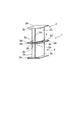
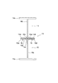
図1は本発明を適用した一実施形態の梁構造体の構成例について梁構造体の長手方向に直交する方向の切断面を示す正面図、図2は梁構造体を構成する上梁部と下梁部の接合箇所について拡大して示した部分正面図、図3は上梁部や下梁部の構成を単独で示した正面図、図4は梁構造体の組み立て工程の概略について示した図、図5は梁構造体を短く切断して全体を示した斜視図である。 FIG. 1 is a front view showing a cut surface in a direction perpendicular to the longitudinal direction of a beam structure in a configuration example of a beam structure according to an embodiment to which the present invention is applied, and FIG. 2 is an upper beam portion constituting the beam structure. FIG. 3 is a front view showing the configuration of the upper beam portion and the lower beam portion independently, and FIG. 4 shows an outline of the assembly process of the beam structure. FIG. 5 and FIG. 5 are perspective views showing the entire beam structure cut short.
図1に示した梁構造体1は、上梁部2と下梁部3を上下に接合して構成される梁構造体である。
A
図1に示されるように、上梁部2は、梁の上側のフランジを形成するフランジ部2eと、下梁部3との接合部2aと、フランジ部2eと接合部2aを繋ぐウェブ形成部2b,2bとよりなり、また、下梁部3は、梁の下側のフランジを形成するフランジ部3eと、上梁部1との接合部3aと、フランジ部3eと接合部3aを繋ぐウェブ形成部3b,3bとよりなる。
As shown in FIG. 1, the
そして、上梁部2の接合部2aには、上梁部2のウェブ形成部2b,2bの面と直交して該ウェブ形成部2b,2bの左右に延出する接合フランジ部2d,2dが形成される一方、下梁部3の接合部3aには、下梁部3のウェブ形成部3b,3bの面と直交して該ウェブ形成部3b,3bの左右に延出する接合フランジ部3d,3dが形成されて、上梁部2の接合フランジ部2d,2dと下梁部3の接合フランジ部3d,3dが互いに重合するようになっている。
And the
更に、上梁部2の接合部2aには係止部2c,2cが一体に形成され、下梁部3の接合部3aには係止部3c,3cが一体に形成されている。
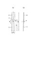
図4(a)に示されるように、上梁部2の接合部2aと下梁部3の接合部3aを、各梁部2,3の長手方向およびウェブ形成部2b,3bの面に対して直交する方向に僅かにオフセットした状態にあっては、係止部2c,2cと係止部3c,3cが干渉することはなく、上梁部2の接合部2aと下梁部3の接合部3aとの密着状態が許容される。
また、図4(b)のように、上梁部2と下梁部3を前述のオフセットの方向と逆向き、つまり、図4中で上梁部2が右に向かうようにして、下梁部3に対して上梁部2を相対移動させ、上梁部2と下梁部3の中心軸を一致させた状態にあっては、上梁部2の係止部2c,2cと下梁部3の係止部3c,3cが、上梁部2と下梁部3の重合方向、つまり、図4(b)中の上下方向に重なり合って相互に嵌合し、上梁部2と下梁部3を上下方向に固定する。
Furthermore, locking
As shown in FIG. 4A, the
Further, as shown in FIG. 4 (b), the
この実施形態にあっては、上梁部2および下梁部3は共にアルミニウム合金を押出成形した押出形材によって形成されており、上梁部2の係止部2c,2cと下梁部3の係止部3c,3c、および、上梁部2の接合フランジ部2d,2dと下梁部3の接合フランジ部3d,3dの断面形状は完全に同一であり、更には、上梁部2も下梁部3も共に同じ幅の中空部を相互間に形成された2枚のウェブ形成部2b,2bあるいはウェブ形成部3b,3bを備えた構造を有するものである。
従って、上梁部2と下梁部3は同じ押出ダイスを使用して形成することができ、梁構造体1の製造コストの低減化の面で有利である。
In this embodiment, the
Therefore, the
上梁部2と下梁部3は完全に同一形状であるから、ここでは、上梁部2を例にとって其の詳細な形状を図3に示している。
Since the
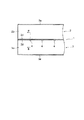
上梁部2と下梁部3との結合部の状態を拡大して図2に示す。この実施形態では、上梁部2の係止部2cと下梁部3の係止部3cを断面略L字型のものとし、それぞれを2列に亘って形成しているが、上梁部2の係止部2cと下梁部3の係止部3cは1列のみであってもよく、あるいは、3列以上とすることも可能である。
FIG. 2 is an enlarged view of the state of the connecting portion between the
上梁部2と下梁部3の各々には、組み立て前の段階で、予め、腐食防止のための陽極酸化皮膜が形成されている。
Each of the
梁構造体1の組み立てに際しては、まず、図4(a)に示されるように、下梁部3の接合部3aとの関係において、上梁部2の接合部2aを各梁部2,3のウェブ形成部2b,2bおよびウェブ形成部3b,3bの面に対して直交する方向、つまり、図4(a)中の左方向にオフセットした状態で、下梁部3の接合部3aの上に上梁部2の接合部2aを密着させて載置する。
When assembling the
次いで、図4(b)に示されるようにして上梁部2と下梁部3の中心軸が一致するまで、前述のオフセットの方向と逆向き、つまり、右側に向けて上梁部2の方を相対移動させることにより、上梁部2の接合部2aに形成されている係止部2c,2cと下梁部3の接合部3aに形成されている係止部3c,3cとを各梁部2,3の重合方向、つまり、図4(b)中の上下方向に重なり合わせる。
この結果、図2に示されるように、これらの係止部2c,2cと係止部3c,3cが相互に嵌合し、係止部2c,2cと係止部3c,3cを介して、上梁部2と下梁部3が互いに係合される。
Next, as shown in FIG. 4B, until the central axes of the
As a result, as shown in FIG. 2, the locking
このように、ウェブ形成部2b,2bおよびウェブ形成部3b,3bの面に対して直交する方向に向けて上梁部2を僅かに相対移動させるだけで係止部2c,2cと係止部3c,3cを嵌合させることができるので、長尺のジョイント部材を上梁部や下梁部の長手方向つまり図4(b)中の紙面垂直方向に向けて押し込むようにした従来構造のものと比べ、組み立てに要する組み立て工数が軽減され、作業スペースも低減される(従来型のジョイント部材は全体として梁構造体1の全長と同程度のスパンを有するので、ジョイント部材の押し込み作業に際しては、仮に、ジョイント部材を分割構造としたとしても、相当の作業スペースが必要であった)。
As described above, the locking
次に、上梁部2の接合部2aの両側から上梁部2のウェブ形成部2b,2bの面と直交する方向に延出した上梁部2の接合フランジ部2d,2dと下梁部3の接合部3aの両側から下梁部3のウェブ形成部3b,3bの面と直交する方向に延出した下梁部3の接合フランジ部3d,3dとの重合部に対し、クリンチ式のカシメ4を施す。
これにより、上梁部2の接合フランジ部2d,2dと下梁部3の接合フランジ部3d,3dとが、接合フランジ部の面に沿った方向、つまり、図4(b)中の前後左右方向で確実に固定される。
Next, the
Thereby, the joining
図6は図1の梁構造体1を示した右側面図、また、図7は図1の梁構造体1を示した平面図である(但し、平面図は時計方向に90°回転させた状態で記載している)。
6 is a right side view showing the
この実施形態では、上下に重合する接合フランジ部2dと接合フランジ部3dが、梁構造体1の長手方向、つまり、図6および図7の左右方向に沿って一定の間隔を空けて、複数の箇所でクリンチ式のカシメ4によって固定されている。
In this embodiment, the joining
クリンチ式のカシメ4は引張せん断強度に優れており、しかも、複数の箇所で接合フランジ部2dと接合フランジ部3dを固定しているので、上梁部2の接合部2aや接合フランジ部2dが下梁部3の接合部3aや接合フランジ部3dに対して接合フランジ部の面に沿った方向、特に、図6および図7の左右方向に不用意に移動するといった不都合が確実に解消される。
従って、この梁構造体1を梁として使用した際に、両端支持の状態で梁構造体1に荷重が作用したとしても、上梁部2と下梁部3の当接面に不用意な滑りが生じることはなく、上梁部2と下上梁部3とが常に一体化したまま撓むことになるので、他の条件が同一の完全一体型の梁構造体と比較しても同等、あるいは、其れ以上に曲げモーメントに対する十分な強度と剛性が発揮され得る。
The clinch-
Therefore, when this
しかも、この実施形態で採用しているクリンチ式のカシメ4は、梁構造体1の長手方向、つまり、図6および図7の左右方向に沿って相対的に長く、各梁部2,3のウェブ形成部2b,2bおよびウェブ形成部3b,3bの面と直交する方向つまり図7の上下方向に沿って短く形成された略矩形状のものであって、特に、梁構造体1の長手方向すなわち図6および図7の左右方向に沿って作用する引張せん断荷重を受けた場合の引張せん断強度に優れているので、上梁部2と下梁部3の当接面に生じる長手方向の不用意な滑りの発生を防止するのに効果的である。
Moreover, the clinch-
クリンチ式のカシメ4の断面形状を図8(a)の拡大図(図1のA−A断面)に示す。なお、図8(a)の方向性は図6の方向性と同じである。また、図8(b)は図6のB−B拡大断面であり、カシメ4に関わる各部の具体的な寸法については図8(c)および図8(d)に示す。なお、図8(d)にも図8(a)、図8(b)の切断方向を参考にA−A、B−Bにて示した。
クリンチ式のカシメ4を成形するためのパンチ&ダイの構成等に関しては既に公知であるので、ここでは特に説明しない。
The cross-sectional shape of the clinch-
Since the configuration of the punch and die for forming the
以上に述べた通り、梁構造体1の組み立てに際しては、ボルト&ナットや溶接工程さらには特段の後加工も必要がないので、ボルト&ナットや梁構造体を構成する素材のイオン化傾向の違いによって生じる電気化学的な腐食、および、加熱に伴う素材自体の恒常的な歪の発生や熱による強度の低下、更には、歪の発生に伴う機械的な強度の低下も未然に防止することができ、生産コストや組み立て工数の軽減化も容易である。
As described above, when assembling the
また、ボルト孔の穿設作業や溶接工程が不要であることから、加熱や切削加工による酸化皮膜の損傷が防止され、当初に形成された酸化皮膜を長期間に亘って温存することができる。 Moreover, since the drilling operation and the welding process of the bolt hole are unnecessary, damage to the oxide film due to heating or cutting is prevented, and the originally formed oxide film can be preserved for a long period of time.
組み立てを終えた梁構造体1の使用状態において上梁部2と下梁部3に作用する力のうち、梁構造体1を上下に押圧する方向の力は、下梁部3の接合部3aと上梁部2の接合部2aとの当接面、および、上梁部2の接合フランジ部2dと下梁部3の接合フランジ部3dとの当接面が上記に通り一体化されているので梁構造体1の全体が完全な1つの梁構造体として支えられる。
Of the forces acting on the
また、上梁部2と下梁部3を引き剥がす方向の引張力は、図2に示されるような上梁部2の係止部2c,2cと下梁部3の係止部3c,3cとの嵌合面、および、上梁部2の接合フランジ部2dと下梁部3の接合フランジ部3dを接合するクリンチ式のカシメ部分4によって支えられる。
クリンチ式のカシメ4の構造を示した図8(a),(b)の拡大断面図からも分かるように、クリンチ式のカシメ4それ自体は、剥離強度つまり上下方向の引張力に関して必ずしも十分な強度を備えないが、上梁部2と下梁部3は、上梁部2の係止部2c,2cと下梁部3の係止部3c,3cを重合させて嵌合することによって上下方向に固定されているので、梁構造体1を全体としてみると、専ら、係止部2c,2cと係止部3c,3cの強度に依存するかたちで、上梁部2と下梁部3を引き剥がす方向の力に対しても十分な強度を発揮することができる。
Further, the tensile force in the direction of peeling the
As can be seen from the enlarged sectional views of FIGS. 8A and 8B showing the structure of the clinch-
また、上梁部2の接合フランジ部2dと下梁部3の接合フランジ部3dは、各梁部2,3のウェブ形成部2b,2bおよびウェブ形成部3b,3bの面と直交するかたちで各ウェブ形成部の左右両側に大きく延出しており、梁の弱軸断面2次モーメントが大きくなったため、梁の全体の横倒れ座屈強度も大きくなる。
Further, the joining
しかも、各梁部2,3のウェブ形成部2b,2bおよびウェブ形成部3b,3bの面と直交するかたちで各ウェブ形成部の両側に十分に延出した接合フランジ部2d,3dそれ自体が、図6に示されるように、梁構造体1の上下方向の中央部で長手方向に沿って延びる水平補剛材として機能することになるので、水平補剛材を備えていない同等の寸法の梁構造体と比べ、より高い局部座屈強度と横倒れ座屈強度を得ることができる。この際、水平補剛材による局部座屈強度と横倒れ座屈強度の向上にあわせてウェブ板を薄型化することができるので、材料の節約にもなる。
Moreover, the joining
次に、梁構造体1の各部の強度試験および耐久試験等の結果について簡単に説明する。
Next, the results of the strength test and durability test of each part of the
図9および図10は、実施形態の梁構造体1において接合フランジ部2dと接合フランジ部3dを固定するクリンチ式のカシメ4の引張せん断強度を試験するために、各梁部2,3と同一材料によって形成された試験片5,6について示した図である。
試験片5は上梁部2の接合フランジ部2dに相当し、また、試験片6は下梁部3の接合フランジ部3dに相当する。
試験片5,6の厚さは実施形態の接合フランジ部2d,3dと同じく3.8mmであり、試験片5,6の縦横の長さは図9および図10に示される通り150mm×40mmであって、試験片5,6の長手方向の端部を50mmだけ重合させて、この重合部分にクリンチ式のカシメ4が施されている。
カシメ4の寸法は実施形態の梁構造体1のものと同じく図8(c),(d)に示される通り、表面における矩形部の長手方向の寸法が15.5mm、これと直交する方向の幅が6mm(以上、図8(d)参照)、表面から底の部分までの寸法が6mm、底の部分の長手方向の寸法が8.6mm(以上、図8(c)参照)となっている。
このうち、図9の試験片5,6は引張方向(図9の上下方向)に対してクリンチ式のカシメ4の長手方向が直交するようにしてクリンチ式のカシメ4を施され、また、図10の試験片5,6は引張方向(図10の上下方向)に対してクリンチ式のカシメ4の長手方向が一致するようにしてクリンチ式のカシメ4を施されている。
従って、この実施形態の梁構造体1の長手方向、つまり、図6および図7の左右方向に沿って長く、各梁部2,3のウェブ形成部2b,2bおよびウェブ形成部3b,3bの面と直交する方向つまり図7の上下方向に沿って短く形成された縦横比を有する本実施形態のカシメ4と同等の条件にあるカシメ4は、図10で示される方のカシメ4ということになる。
なお、試験片5,6の端部を挾持して引張方向の荷重を測定する試験機については既に公知である。
9 and 10 are the same as those of the
The
The thickness of the
The size of the
Among these, the
Therefore, it is long along the longitudinal direction of the
Note that a testing machine that grips the ends of the
また、図11は本実施形態の梁構造体1において接合フランジ部2dと接合フランジ部3dを固定するクリンチ式のカシメ4の剥離強度を試験するために、各梁部2,3と同一材料によって形成された試験片7,8によって構成される十字引張試験体ついて示した図である。
試験片7は上梁部2の接合フランジ部2dに相当し、また、試験片8は下梁部3の接合フランジ部3dに相当する。
試験片7,8の厚さは実施形態の接合フランジ部2d,3dと同じく3.8mmであり、試験片7,8の縦横の長さは図11に示される通り、共に150mm×50mmであって、試験片7,8の中央部を直交させた状態で重合して、この重合部分にクリンチ式のカシメ4が施されている。
カシメ4の寸法は前記と同様に表面における矩形部の長手方向の寸法が15.5mm、これと直交する方向の幅が6mm、表面から底の部分までの寸法が6mm、底の部分の長手方向の寸法が8.6mmである。
試験片8を固定した状態で試験片7を図11の紙面垂直方向に引き上げることによって剥離方向の荷重を測定する試験機については公知である。なお、試験片7,8の孔は、これらの試験片7,8を試験機に取り付ける際に使用するもので、試験の内容それ自体とは無関係である。
Further, FIG. 11 shows the same material as the
The
The thickness of the
The size of the
A testing machine that measures the load in the peeling direction by pulling up the
まず、図9の試験片5,6を利用した引張せん断試験の結果と図10の試験片5,6を利用した引張せん断試験の結果、および、図11の十字引張試験体(試験片7,8)を利用した剥離強度試験の結果を纏めて図12の表に示す。
図12の表において垂直方向のかしめは図9の試験体にてカシメの長手方向と直交方向に引張力を加えて引張せん断試験の結果で、平行方向のかしめは図10の試験体にてカシメの長手方向と平行方向に引張力を加えての引張せん断試験の結果である。
表よりカシメの長手方向とそれに垂直な方向とでは引張せん断強度に大きな相違は見られなかった。
なお、何れの試験結果も、同様の試験片を3組ずつ用意して繰り返し行なった3回の試験の平均値である。
First, the result of the tensile shear test using the
In the table of FIG. 12, the caulking in the vertical direction is the result of the tensile shear test by applying a tensile force in the direction perpendicular to the longitudinal direction of the caulking in the specimen of FIG. 9, and the caulking in the parallel direction is caulking in the specimen of FIG. It is the result of a tensile shear test in which a tensile force is applied in a direction parallel to the longitudinal direction of the film.
From the table, there was no significant difference in tensile shear strength between the longitudinal direction of crimping and the direction perpendicular thereto.
Each test result is an average value of three tests in which three sets of similar test pieces were prepared and repeated.
図13はクリンチ式のカシメ4継手に対する一面せん断疲労試験の結果を示したP−N線図であり、図10と同様の試験片を使用した。
横軸が疲労試験の繰り返し回数、そして、縦軸が疲労破壊荷重である。荷重比(R)は0.1とした。
試験片が107回の繰返し数を超えて破壊しない場合,試験を中断し,107回の疲労強度とする。つまり、クリンチ式カシメ4継手の107回に対応する疲労強度は2444Nである。
FIG. 13 is a PN diagram showing the results of a one-sided shear fatigue test for clinch-type caulking four joints, and a test piece similar to FIG. 10 was used.
The horizontal axis is the number of repetitions of the fatigue test, and the vertical axis is the fatigue fracture load. The load ratio (R) was 0.1.
If the specimen does not break beyond 10 7 repetitions, the test is discontinued and the fatigue strength is 10 7 times. That is, fatigue strength corresponding to 10 7 times clinch
図14は本実施形態の梁構造体1を構成する上梁部2および下梁部3に対して曲げ試験を行なうための試験機の構成について簡略化して示した模式図である。
この曲げ試験機9は、梁構造体1を両端単純支持の梁として使用した場合の状況を再現するための装置である。
曲げ試験を行なった梁構造体1は図1に示されるような断面形状を有する梁構造体1であって、上梁部2および下梁部3の高さが共に125mmつまり全高が250mmであり、接合フランジ部2d,3dと上梁部2のフランジ部2eおよび下梁部3のフランジ部3eの横幅が共に100mm、ウェブ形成部2b,3bの厚さは左右共に2.5mm、接合フランジ部2d,3dの厚さは共に3.8mm、上梁部2のフランジ部2eと下梁部3のフランジ部3eの厚さは共に5mmであり、図14に示されるように、実際に曲げられる部分の長さは3800mmであって、その中央部に荷重が加えられる。
クリンチ式のカシメ4は、梁構造体1の長手方向つまり図14の左右方向に沿って100mmの間隔を置いて断続的に設けられている。
ローラ10,11は梁構造体1の両端部を支えて水平状態を保持すると共に、梁構造体1の両端部に無用な外力や抵抗あるいは拘束力が作用するのを防止するためのコロとして機能する。
また、押圧具12は、梁構造体1の中央部に無用な抵抗や拘束力が作用するのを防止した状態で梁構造体1の中央部に鉛直方向の荷重を加えるための手段である。
FIG. 14 is a schematic diagram showing a simplified configuration of a testing machine for performing a bending test on the
This bending tester 9 is a device for reproducing the situation when the
The
The clinch-
The
The
曲げ試験の結果を図15の線図に示す。横軸が梁構造体1における中央部の撓み、そして、縦軸が荷重であり、比較の都合上、同等の形状および寸法を有する完全一体型の梁構造体の理論上の撓み量を併せて記載している。
図15から分かるように、同一の荷重に対する撓み量は、完全一体型の梁構造体も上梁部2および下梁部3からなる実施形態の梁構造体1も同等である。
つまり、この実施形態の梁構造体1は、曲げ荷重に関する限り、同等の形状および寸法を有する完全一体型の梁構造体に比して何らの遜色もない。
The results of the bending test are shown in the diagram of FIG. The horizontal axis is the deflection of the central portion of the
As can be seen from FIG. 15, the deflection amount with respect to the same load is the same for both the completely integrated beam structure and the
That is, the
図16は梁構造体1の3点曲げ疲労試験前後の荷重とたわみの関係を示した線図である。比較の都合上、油圧サーボパルサーを使用して10万回の3点曲げ疲労試験を繰り返した後の梁構造体1と、図14に示したものと同じ条件で未使用の梁構造体1と、図14に示したものと同じ条件を有する完全一体型の梁構造体の各々について、荷重と中央部のたわみの関係を独立的に記載している。
10万回の3点曲げ疲労試験を繰り返した梁構造体1および未使用の梁構造体1の寸法は、前記と同様、上梁部2および下梁部3の高さが共に125mmで全高が250mm、接合フランジ部2d,3dと上梁部2のフランジ部2eおよび下梁部3のフランジ部3eの横幅が共に100mm、ウェブ形成部2b,3bの厚さは左右共に2.5mm、接合フランジ部2d,3dの厚さは共に3.8mm、上梁部2のフランジ部2eと下梁部3のフランジ部3eの厚さは共に5mmであり、クリンチ式のカシメ4は、梁構造体1の長手方向に沿って100mmの間隔を置いて断続的に設けられており、実際に屈曲される部分の長さは3800mm(全長は4000mm)である。完全一体型の梁構造体の寸法もこれと同様である。
10万回の疲労試験では最大荷重を2000kgf、また、荷重比(R)は0.1とし、繰返し速度は0.6Hzとしている。
図16から分かる通り、10万回の3点曲げ疲労試験を繰り返した後の梁構造体1の曲げ強度は、未使用の梁構造体1や完全一体型の梁構造体の曲げ強度と同等であり、梁構造体1を上梁部2および下梁部3からなる分割構成としても、交番荷重による曲げ剛性の劣化が生じ難いことが窺える。
FIG. 16 is a diagram showing the relationship between the load and deflection of the
As for the dimensions of the
In a 100,000 fatigue test, the maximum load is 2000 kgf, the load ratio (R) is 0.1, and the repetition rate is 0.6 Hz.
As can be seen from FIG. 16, the bending strength of the
次に、上梁部2の係止部2c,2cと下梁部3の係止部3c,3cの嵌合で得られる上梁部2と下梁部3の固定効果、および、上梁部2の接合フランジ部2d,2dと下梁部3の接合フランジ部3d,3dを接合するクリンチ式のカシメ4で得られる上梁部2と下梁部3の固定効果を確認するために行なった剥離試験について説明する。
この剥離試験で用いた梁構造体1は図1,図4(b)ないし図5に示されるもので、その寸法は、上梁部2および下梁部3の高さが共に125mmで全高が250mm、接合フランジ部2d,3dと上梁部2のフランジ部2eおよび下梁部3のフランジ部3eの横幅が共に100mm、ウェブ形成部2b,3bの厚さは左右共に2.5mm、接合フランジ部2d,3dの厚さは共に3.8mm、上梁部2のフランジ部2eと下梁部3のフランジ部3eの厚さは共に5mmであり、上梁部2の係止部2cと下梁部3の係止部3cの板厚は3mmであって、両者の嵌合幅は4.5mmである。また、長手方向つまり図4(b)ないし図5の紙面奥行き方向の寸法が100mmである。
この試験では、同寸法の前記梁構造体1を3個用意し、その内の1つにはクリンチ式のカシメ4を施さず、上梁部2の係止部2c,2cと下梁部3の係止部3c,3cとの嵌合のみによって上梁部2と下梁部3を固定して試験体Aとした。他の1つには、上梁部2の係止部2c,2cと下梁部3の係止部3c,3cとを嵌合させた状態で、更に、左右で対を成す一方の接合フランジ部2d,3dともう一方の接合フランジ部2d,3dの中央部の各々1箇所にクリンチ式のカシメ4を施して試験体Bとした(従って、カシメ4の総数は都合2箇所)。最後の1つには、上梁部2の係止部2c,2cと下梁部3の係止部3c,3cとを嵌合させた状態で、更に、左右で対を成す一方の接合フランジ部2d,3dともう一方の接合フランジ部2d,3dの長手方向を長手方向に3等分する位置にクリンチ式のカシメ4を施して試験体Cとした(従って、カシメ4の総数は左右各2箇所で都合4箇所)。
そして、試験体A,B,Cの各々に対し、上梁部2と下梁部3を相対的に離間させる方向、つまり、図4(b)ないし図5の上下方向に引張して剥離試験を行ない、その結果を図17の表に示した。
図17に示される通り、試験体Bの剥離強度は試験体Aの剥離強度の約1.3倍、また、試験体Cの剥離強度は試験体Aの剥離強度の約1.4倍となっている。また、試験体Aの剥離強度と試験体Bの剥離強度の差分を2で割った値(4640N/1カシメ箇所)と試験体Aの剥離強度と試験体Cの剥離強度の差分を4で割った値(3176N/1カシメ箇所)とは近似せず、このことから、クリンチ式のカシメ4の数を無闇に増やしても、其の増加分に応じて比例的に剥離強度を増大するとは考え難い。何れにしても、剥離に対する強度の大半は、専ら、上梁部2の係止部2c,2cと下梁部3の係止部3c,3cとの嵌合で生じる固定力(32644N)に依存するものと推定される。
つまり、前述のように、クリンチ式のカシメ4それ自体は、剥離強度つまり上下方向の引張に関して必ずしも十分な強度は備えないが、上梁部2と下梁部3は上梁部2の係止部2c,2cと下梁部3の係止部3c,3cを重合させるようにして嵌合固定されているので、梁構造体1を全体としてみると、専ら、係止部2c,2cと係止部3c,3cの強度に依存するかたちで、上梁部2と下梁部3を引き剥がす方向の力に対して強度を発揮しているということができる。
Next, the fixing effect of the
The
In this test, three
Then, with respect to each of the test bodies A, B, and C, a peel test is performed by pulling the
As shown in FIG. 17, the peel strength of Specimen B is about 1.3 times the peel strength of Specimen A, and the peel strength of Specimen C is about 1.4 times the peel strength of Specimen A. ing. Also, the difference between the peel strength of the test specimen A and the peel strength of the test specimen B divided by 2 (4640 N / 1 caulking location) and the difference between the peel strength of the test specimen A and the peel strength of the test specimen C are divided by four. Therefore, even if the number of clinch-
That is, as described above, the clinch-
図18は本発明を適用した他の一実施形態の梁構造体13の構成について梁構造体13の長手方向に直交する方向の切断した断面で示した正面図である。
FIG. 18 is a front view showing a configuration of a
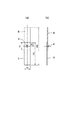
この実施形態は、中空部を形成された二枚板状のウェブ形成部に代えて中空部のない一枚板状のウェブ形成部を採用した点、および、上梁部と下梁部の接合部の夫々に2列に亘って形成された係止部に代えて単列の係止片を各接合部に一組のみ採用した点で前述の実施形態と異なる。 In this embodiment, instead of the two-plate-shaped web forming portion in which the hollow portion is formed, a single-plate-shaped web forming portion having no hollow portion is adopted, and the upper beam portion and the lower beam portion are joined. It differs from the above-described embodiment in that only one set of single-row locking pieces is adopted for each joint portion instead of the locking portions formed in two rows in each portion.
この梁構造体13は、上梁部14と下梁部15で構成される。上梁部14は、梁の上側のフランジを形成するフランジ部14eと、下梁部15との接合部14aと、フランジ部14eと接合部14aを繋ぐウェブ形成部14bとよりなり、また、下梁部15は、梁の下側のフランジを形成するフランジ部15eと、上梁部14との接合部15aと、フランジ部15eと接合部15aを繋ぐウェブ形成部15bとよりなる。
The
そして、上梁部14の接合部14aには、上梁部14のウェブ形成部14bの面と直交して該ウェブ形成部14bの左右に延出する接合フランジ部14d,14dが形成される一方、下梁部15の接合部15aには、下梁部15のウェブ形成部15bの面と直交して該ウェブ形成部15bの左右に延出する接合フランジ部15d,15dが形成されて、上梁部14の接合フランジ部14d,14dと下梁部15の接合フランジ部15d,15dが互いに重合するようになっている。
The
更に、上梁部14の接合部14aには係止部14cが一体に形成され、下梁部15の接合部15aには係止部15cが一体に形成されている。
上梁部14の接合部14aと下梁部15の接合部15aを各梁部14,15のウェブ形成部14b,15bに対して直交する方向に僅かにオフセットした状態にあっては、係止部14cと係止部15cが干渉することはなく、上梁部14の接合部14aと下梁部15の接合部15aとの密着状態が許容される(以上、図示略)。
また、図18のように、上梁部14と下梁部15の中心軸を一致させた状態にあっては、上梁部14の係止部14cと下梁部15の係止部15cが、上梁部14と下梁部15の重合方向、つまり、図18中の上下方向に重なり合って相互に嵌合し、上梁部14と下梁部15を上下方向に固定する。
Further, a locking
When the joint 14a of the
Further, as shown in FIG. 18, when the central axes of the
上梁部14および下梁部15は共にアルミニウム合金の押出形材によって形成されており、上梁部14の係止部14cと下梁部15の係止部15c、および、上梁部14の接合フランジ部14d,14dと下梁部15の接合フランジ部15d,15dの断面形状は完全に同一であり、同じ断面形状の押出形材を使用して形成することができる。
Both the
上梁部14と下梁部15は同一形状であるから、ここでは、上梁部14を例にとって其の詳細な形状を図19に示している。つまり、図19に示される上梁部14を図19の平面内で180°回転させたものと図18に示される下梁部15とは同じである。
Since the
以上のように、図1の実施形態で示した梁構造体1との相違は、中空部を形成された二枚板状のウェブ形成部2b,2bおよび3b,3bに代えて中空部のない一枚板状のウェブ形成部14bおよびウェブ形成部15bを採用した点、および、上梁部と下梁部の接合部の夫々に2列に亘って形成された係止部に代えて単列の係止片14c,15cを一組のみ採用した点にある。
その他の構成,組み立て方法,効果に関しては、図1で示した前述の実施形態の場合と同様であるので、詳細な説明は省略する。
なお、図18中の符号14eは上梁部14が備える上側のフランジを形成するフランジ部、符号15eは下梁部15が備える下側のフランジを形成するフランジ部であり、符号16はクリンチ式のカシメである。
As described above, the difference from the
Other configurations, assembly methods, and effects are the same as those in the above-described embodiment shown in FIG.
In FIG. 18,
図20は本発明を適用した更に別の一実施形態の梁構造体17の構成について梁構造体17の長手方向に直交する方向の切断面を示す正面図である。
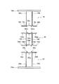
FIG. 20 is a front view showing a cut surface in a direction perpendicular to the longitudinal direction of the
この梁構造体17は、3つの梁構成体、すなわち上梁部18と中間梁部19と下梁部20を上下に接合して構成される梁構造体であり、上梁部と下梁部との間に中間梁部が介装されている点で、前述した2つの実施形態とは構成が異なる。
This
上梁部18,中間梁部19,下梁部20を分割した状態で各部の形状の詳細を図21に示す。
FIG. 21 shows details of the shape of each part in a state where the
上梁部18の構造(寸法は除く)は、図1に示した実施形態の上梁部2と同様であり、ウェブ形成部18b,18bと接合部18a、および、係止部18c,18cと接合フランジ部18d,18d、ならびに、上側のフランジを形成するフランジ部18eを備える。
The structure (excluding dimensions) of the
また、下梁部20の構造(寸法は除く)は、図1に示した実施形態の下梁部3と同様であり、ウェブ形成部20b,20bと接合部20a、および、係止部20c,20cと接合フランジ部20d,20d、ならびに、下側のフランジを形成するフランジ部20eを備える。
Further, the structure (excluding dimensions) of the
中間梁部19に関しては、本実施形態に固有の構成である。この中間梁部19は、図21に示すように、上梁部18と接合される上接合部19auと、下梁部20と接合される下接合部19alと、これらの接合部19au,19alを繋ぐウェブ形成部19b,19bとよりなる。このウェブ形成部19b,19bは、中空部を形成された二枚板状のウェブ形成部である。
そして、上梁部18と接合する上接合部19auには、上梁部18の接合部18aと中間梁部19の上接合部19auを各梁部18,19のウェブ形成部18b,19bの面に対して直交する方向にオフセットした状態にあっては上梁部18の接合部18aと中間梁部19の上接合部19auとの密着を許容する一方(以上、図示略)、上梁部18と中間梁部19の中心軸を一致させた状態で上梁部18と中間梁部19の重合方向つまり図20の上下方向に重なり合って上梁部18の係止部18c,18cと嵌合する係止部19cu,19cuが一体に設けられている。
また、中間梁部19の上接合部19auの両側には、中間梁部19のウェブ形成部19b,19bの面と直交して該ウェブ形成部19b,19bの両側に延出する接合フランジ部19du,19duが一体に設けられている。
The
Then, the upper joint portion 19au joined to the
Further, on both sides of the upper joint portion 19au of the
これらと同様、中間梁部19において下梁部20と接合する下接合部19alには、中間梁部19の下接合部19alと下梁部20の接合部20aを各梁部19,20のウェブ形成部19b,20bの面に対して直交する方向にオフセットした状態にあって中間梁部19の下接合部19alと下梁部20側の接合部20aとの密着を許容する一方(以上、図示略)、中間梁部19と下梁部20の中心軸を一致させた状態で中間梁部19と下梁部20の重合方向つまり図20の上下方向に重なり合って下梁部20の係止部20c,20cと嵌合する係止部19cl,19clが一体に設けられている。
また、中間梁部19の下接合部19alの両側には、中間梁部19のウェブ形成部19b,19bの面と直交して該ウェブ形成部面19b,19bの両側に延出する接合フランジ部19dl,19dlが一体に設けられている。
Similarly to these, the lower joint portion 19al joined to the
Further, on both sides of the lower joint portion 19al of the
この実施形態にあっては、上梁部18および下梁部20と中間梁部19は共にアルミ押出成形によって形成されており、上梁部18の係止部18c,18cと下梁部20の係止部20c,20c、および、上梁部18の接合フランジ部18d,18dと下梁部20の接合フランジ部20d,20dの断面形状が完全に同一であり、更には、上梁部18も下梁部20も共に同じ幅の中空部を間に形成された2枚のウェブ形成部18b,18bあるいはウェブ形成部20b,20bを備えた構造を有するものであるので、上梁部18と下梁部20を同じ形状の押出形材を使用して形成することができ、梁構造体17の製造コストの低減化の面で有利である。
In this embodiment, the
つまり、上梁部18と下梁部20は同じ形状であって、図21に示される上梁部18を図21の平面内で180°回転させたものと、図21に示される下梁部20とは同じ形状である。
That is, the
梁構造体17の組み立て方法は、基本的には、図1で示した実施形態の場合と同様であるが、本実施形態の梁構造体17にあっては、上梁部18,中間梁部19,下梁部20といった3つの構成要素が存在するので、最初に下梁部20と中間梁部19を組み立て、然る後に、中間梁部19の上に改めて上梁部18を組み付けるようにするとよい。
下梁部20に対する中間梁部19の組み付け作業は、図4(a)および図4(b)に示したような手順で行うことができ、同様に、下梁部20に対する組み付け作業を終えた中間梁部19に対する上梁部18の組み付け作業も、図4(a)および図4(b)に示したような手順で行うことができる。
The method of assembling the
The assembly work of the
図20中の符号21はクリンチ式のカシメである。
図20に示した梁構造体17は、上梁部18,中間梁部19,下梁部20を一体的に組み合わせることにより、全体として2組の水平補剛材、つまり、上梁部18の接合フランジ部18dおよび中間梁部19の接合フランジ部19duからなる第一の水平補剛材と、中間梁部19の接合フランジ部19dlおよび下梁部20の接合フランジ部20dからなる第二の水平補剛材とを備えることになるので、ウェブ面板の局部座屈強度と梁全体の横倒れ座屈強度の向上が期待できる。これにより、ウェブ板の更なる薄型化も可能である。
梁構造体を上下に3以上に分割して構成しても曲げ強度や疲労強度が低下しないことは、曲げ荷重に関する図15の試験結果や疲労強度に関する図16の試験結果からも明らかである。
つまり、図15や図16の試験結果から分かる通り、完全一体型の梁構造体と上下に2分割して構成された梁構造体1との間では、曲げ強度や疲労強度に関する明確な差異は生じていないので、上下に3分割して構成された梁構造体17の性能が、上下に2分割して構成された梁構造体1と同等と考えられる。
The
It is apparent from the test results of FIG. 15 regarding the bending load and the test results of FIG. 16 regarding the fatigue strength that the beam structure is divided into three or more in the vertical direction so that the bending strength and the fatigue strength do not decrease.
That is, as can be seen from the test results of FIGS. 15 and 16, there is no clear difference in bending strength and fatigue strength between the completely integrated beam structure and the
この実施形態にあっては、上梁部18,下梁部20の断面形状と中間梁部19の断面形状とが相違するので、上梁部18と下梁部20は同じ形状の押出形材を利用できるが、中間梁部19は別の形状の押出形材となる。しかしながら全体を3分割する結果として、用意された押出機で可能な大きさより大きな梁を製造することが可能である。
In this embodiment, since the cross-sectional shapes of the
梁構造体17が奏する其の他の効果に関しては図1で示した実施形態の場合と同様であるので、詳細な説明は省略する。
Since other effects produced by the
この実施形態では1つの中間梁部19のみを上梁部18と下梁部20の間に介装しているが、必要とあれば、上梁部18と下梁部20の間に、同形状・同寸法の中間梁部19を複数個まとめて介装するといったこともできる。
In this embodiment, only one
更には、高さ寸法の異なる複数種の中間梁部19を規格化して製造しておき、梁構造体17として必要とされる全高に応じ、高さ寸法の異なる中間梁部19、もしくは、中間梁部19の組み合わせを適宜に選択して、上梁部18と下梁部20の間に介装して所望する高さの梁構造体17を得るといったことも可能である。
Further, a plurality of types of
上記説明にあっては上梁部と下梁部を同じ形状の押出形材にて形成したが別の形状とすることも可能である。
また、梁構造体17のフランジ部を平面以外の形状とすることも可能である。
またこの場合、押出形材にて形成するためにその断面形状は自由に設計できウェブ形成部を平板でない形状とし他の部品を取り付けやすい形状とする等の変形も可能である。
In the above description, the upper beam portion and the lower beam portion are formed by the extruded shape having the same shape, but may have different shapes.
Moreover, it is also possible to make the flange part of the
In this case, the cross-sectional shape can be freely designed in order to form with an extruded shape, and the web forming portion can be deformed into a shape that is not a flat plate and other components can be easily attached.
1 梁構造体
2 上梁部
2a 接合部
2b ウェブ形成部
2c 係止部
2d 接合フランジ部
2e フランジ部
3 下梁部
3a 接合部
3b ウェブ形成部
3c 係止部
3d 接合フランジ部
3e フランジ部
4 クリンチ式のカシメ
5,6,7,8 試験片
9 曲げ試験機
10,11 ローラ
12 押圧具
13 梁構造体
14 上梁部
14a 接合部
14b ウェブ形成部
14c 係止部
14d 接合フランジ部
14e フランジ部
15 下梁部
15a 接合部
15b ウェブ形成部
15c 係止部
15d 接合フランジ部
15e フランジ部
16 クリンチ式のカシメ
17 梁構造体
18 上梁部
18a 接合部
18b ウェブ形成部
18c 係止部
18d 接合フランジ部
18e フランジ部
19 中間梁部
19au 上接合部
19al 下接合部
19b ウェブ形成部
19cu 係止部
19cl 係止部
19du 接合フランジ部
19dl 接合フランジ部
20 下梁部
20a 接合部
20b ウェブ形成部
20c 係止部
20d 接合フランジ部
20e フランジ部
21 クリンチ式のカシメ
DESCRIPTION OF
Claims (8)
上梁部は梁の上側のフランジを形成するフランジ部と、下梁部との接合部と、フランジ部と接合部を繋ぐウェブ形成部とよりなり、
下梁部は梁の下側のフランジを形成するフランジ部と、上梁部との接合部と、フランジ部と接合部を繋ぐウェブ形成部とよりなり、
上梁部の接合部と下梁部の接合部の各々には、
両梁部材の長手方向と直交し、ウェブ形成部の面に対して直交する方向に相対移動させることによって相互に嵌合する係止部が形成されると共に、
前記上梁部側の接合部と下梁部側の接合部の両側には、各梁部のウェブ面と直交して該ウェブ面の左右に延出し互いに重合する接合フランジ部が形成され、
前記上梁部と下梁部の係止部同士を嵌合させた状態で、
前記上梁部の左右の接合フランジ部と下梁部の左右の接合フランジ部とがそれぞれクリンチ式のカシメによって互いに固定されていることを特徴とした梁構造体。 A beam structure constructed by joining an upper beam part and a lower beam part up and down,
The upper beam part consists of a flange part that forms the upper flange of the beam, a joint part with the lower beam part, and a web formation part that connects the flange part and the joint part,
The lower beam part is composed of a flange part that forms a lower flange of the beam, a joint part with the upper beam part, and a web forming part that connects the flange part and the joint part,
In each of the joint part of the upper beam part and the joint part of the lower beam part,
A locking part is formed that is fitted to each other by moving in a direction perpendicular to the longitudinal direction of both beam members and perpendicular to the surface of the web forming part,
On both sides of the joint portion on the upper beam portion side and the joint portion on the lower beam portion side, a joining flange portion is formed that extends to the left and right of the web surface perpendicular to the web surface of each beam portion and overlaps with each other.
In a state where the locking portions of the upper beam portion and the lower beam portion are fitted together,
A beam structure characterized in that the left and right joint flange portions of the upper beam portion and the left and right joint flange portions of the lower beam portion are fixed to each other by a clinch-type caulking.
上梁部は梁の上側のフランジを形成するフランジ部と、中間梁部との接合部と、フランジ部と接合部を繋ぐウェブ形成部とよりなり、
下梁部は梁の下側のフランジを形成するフランジ部と、中間梁部との接合部と、フランジ部と接合部を繋ぐウェブ形成部とよりなり、
中間梁部は上梁部と接合される上接合部と、下梁部と接合される下接合部とこれらの接合部を繋ぐウェブ形成部とよりなり、
上梁部の接合部と中間梁部の上接合部の各々には、
両梁部材の長手方向と直交し、ウェブ形成部の面に対して直交する方向に相対移動させることによって相互に嵌合する係止部が形成されると共に、
下梁部の接合部と中間梁部の下接合部の各々には、
両梁部材の長手方向と直交し、ウェブ形成部の面に対して直交する方向に相対移動させることによって相互に嵌合する係止部が形成されると共に、
前記上梁部側の接合部と中間梁部側の接合部の両側には、各梁部のウェブ面と直交して該ウェブ面の左右に延出し互いに重合する接合フランジ部が形成され、
前記下梁部側の接合部と中間梁部側の接合部の両側には、各梁部のウェブ面と直交して該ウェブ面の左右に延出し互いに重合する接合フランジ部が形成され、
前記上梁部と中間梁部の係止部同士並びに前記下梁部と中間梁部の係止部同士を嵌合させた状態で、
前記上梁部の左右の接合フランジ部と中間梁部の左右の接合フランジ部とがそれぞれクリンチ式のカシメによって互いに固定されると共に、前記下梁部の左右の接合フランジ部と中間梁部の左右の接合フランジ部とがそれぞれクリンチ式のカシメによって互いに固定されていることを特徴とした梁構造体。 A beam structure configured by vertically joining an upper beam portion, an intermediate beam portion, and a lower beam portion,
The upper beam part is composed of a flange part that forms the upper flange of the beam, a joint part with the intermediate beam part, and a web forming part that connects the flange part and the joint part,
The lower beam part consists of a flange part that forms the lower flange of the beam, a joint part between the intermediate beam part, and a web forming part that connects the flange part and the joint part,
The intermediate beam portion is composed of an upper joint portion joined to the upper beam portion, a lower joint portion joined to the lower beam portion, and a web forming portion connecting these joint portions,
Each of the upper beam joint and the intermediate beam upper joint
A locking part is formed that is fitted to each other by moving in a direction perpendicular to the longitudinal direction of both beam members and perpendicular to the surface of the web forming part,
In each of the joint part of the lower beam part and the lower joint part of the intermediate beam part,
A locking part is formed that is fitted to each other by moving in a direction perpendicular to the longitudinal direction of both beam members and perpendicular to the surface of the web forming part,
On both sides of the joint portion on the upper beam portion side and the joint portion on the intermediate beam portion side, a joining flange portion is formed which extends to the left and right of the web surface perpendicular to the web surface of each beam portion and overlaps with each other.
On both sides of the joint part on the lower beam part side and the joint part on the intermediate beam part side, a joining flange part is formed that extends perpendicularly to the web surface of each beam part and overlaps with each other and overlaps with each other.
In a state where the locking portions of the upper beam portion and the intermediate beam portion and the locking portions of the lower beam portion and the intermediate beam portion are fitted to each other,
The left and right joint flange portions of the upper beam portion and the left and right joint flange portions of the intermediate beam portion are fixed to each other by clinching caulking, and the left and right joint flange portions of the lower beam portion and the left and right joint flange portions of the intermediate beam portion are fixed. A beam structure characterized in that the joint flanges are fixed to each other by clinch type caulking.
Priority Applications (1)
| Application Number | Priority Date | Filing Date | Title |
|---|---|---|---|
| JP2008261226A JP5104703B2 (en) | 2008-10-08 | 2008-10-08 | Beam structure |
Applications Claiming Priority (1)
| Application Number | Priority Date | Filing Date | Title |
|---|---|---|---|
| JP2008261226A JP5104703B2 (en) | 2008-10-08 | 2008-10-08 | Beam structure |
Publications (2)
| Publication Number | Publication Date |
|---|---|
| JP2010090603A true JP2010090603A (en) | 2010-04-22 |
| JP5104703B2 JP5104703B2 (en) | 2012-12-19 |
Family
ID=42253579
Family Applications (1)
| Application Number | Title | Priority Date | Filing Date |
|---|---|---|---|
| JP2008261226A Active JP5104703B2 (en) | 2008-10-08 | 2008-10-08 | Beam structure |
Country Status (1)
| Country | Link |
|---|---|
| JP (1) | JP5104703B2 (en) |
Cited By (4)
| Publication number | Priority date | Publication date | Assignee | Title |
|---|---|---|---|---|
| JP2014514139A (en) * | 2011-03-09 | 2014-06-19 | コック グリッシュ エルピー | Apparatus for supporting internal structure of mass transfer column and process using the same |
| KR101514606B1 (en) * | 2014-08-25 | 2015-04-23 | 강병구 | wide composite beam assembly |
| CN110241971A (en) * | 2019-07-19 | 2019-09-17 | 同济大学建筑设计研究院(集团)有限公司 | A kind of prestressing combination steel structure member and its construction method |
| CN112411873A (en) * | 2020-11-27 | 2021-02-26 | 湖南鸿阳钢结构有限公司 | Expanded H-shaped steel beam |
Citations (1)
| Publication number | Priority date | Publication date | Assignee | Title |
|---|---|---|---|---|
| JP2009215783A (en) * | 2008-03-11 | 2009-09-24 | Shin Nikkei Co Ltd | Combined structural material |
-
2008
- 2008-10-08 JP JP2008261226A patent/JP5104703B2/en active Active
Patent Citations (1)
| Publication number | Priority date | Publication date | Assignee | Title |
|---|---|---|---|---|
| JP2009215783A (en) * | 2008-03-11 | 2009-09-24 | Shin Nikkei Co Ltd | Combined structural material |
Cited By (5)
| Publication number | Priority date | Publication date | Assignee | Title |
|---|---|---|---|---|
| JP2014514139A (en) * | 2011-03-09 | 2014-06-19 | コック グリッシュ エルピー | Apparatus for supporting internal structure of mass transfer column and process using the same |
| KR101514606B1 (en) * | 2014-08-25 | 2015-04-23 | 강병구 | wide composite beam assembly |
| WO2016032207A1 (en) * | 2014-08-25 | 2016-03-03 | (주)씨지스플랜 | Assembly expansion composite beam |
| CN110241971A (en) * | 2019-07-19 | 2019-09-17 | 同济大学建筑设计研究院(集团)有限公司 | A kind of prestressing combination steel structure member and its construction method |
| CN112411873A (en) * | 2020-11-27 | 2021-02-26 | 湖南鸿阳钢结构有限公司 | Expanded H-shaped steel beam |
Also Published As
| Publication number | Publication date |
|---|---|
| JP5104703B2 (en) | 2012-12-19 |
Similar Documents
| Publication | Publication Date | Title |
|---|---|---|
| US7922067B2 (en) | Tailor welded blank assembly and method | |
| JP4972417B2 (en) | Member joining method and structure | |
| JP5104703B2 (en) | Beam structure | |
| US20180009050A1 (en) | Welding structure of press formed part, structural part for automotive body including the welding structure, and method for manufacturing welding part (as amended) | |
| US10124555B2 (en) | Sandwich structure including grooved outer sheet | |
| US10343207B2 (en) | Metal joint body and apparatus for manufacturing the metal joint body | |
| JP6090464B2 (en) | PRESS-MOLDED PRODUCT, PRESS-MOLDED PRODUCTION METHOD, AND PRESS-MOLDED PRODUCTION DEVICE | |
| WO2013157168A1 (en) | Metal joint and building structure | |
| CA2975861A1 (en) | Formed metal item including tubular part with slit, method for producing the same, and producing device and die assembly used in method for producing the same | |
| JP4841252B2 (en) | Assembled H-section steel and its manufacturing method | |
| US9003723B2 (en) | Steel pipe stiffening brace member and manufacturing method thereof | |
| JP6589477B2 (en) | Shaped steel connection structure | |
| US20190001388A1 (en) | Method for manufacturing l-shaped square pipe, device for manufacturing l-shaped square pipe, and l-shaped square pipe | |
| JP2002004495A (en) | Composite beam member and manufacturing method for it | |
| JP2014098609A (en) | Bending test method of weld joint | |
| JP7316878B2 (en) | Fastening structure and fastening method by fastening structure | |
| CN109093272B (en) | Metal member and method for manufacturing the same | |
| US8474903B2 (en) | Serpentine section stabilizer for vehicle pillar | |
| WO2020137387A1 (en) | Element joint and manufacturing method therefor | |
| KR101481976B1 (en) | Welding-beam with waveform web for prefabricated buildings | |
| JP5685705B2 (en) | Back cover for column | |
| JP6540491B2 (en) | Connection member and joint structure of floor joists | |
| JP2591517B2 (en) | How to join sections | |
| JP5382798B2 (en) | Light channel steel with different web thickness and flange thickness. | |
| CN100348805C (en) | Beam joint device |
Legal Events
| Date | Code | Title | Description |
|---|---|---|---|
| A621 | Written request for application examination |
Free format text: JAPANESE INTERMEDIATE CODE: A621 Effective date: 20110105 |
|
| A977 | Report on retrieval |
Free format text: JAPANESE INTERMEDIATE CODE: A971007 Effective date: 20120712 |
|
| TRDD | Decision of grant or rejection written | ||
| A01 | Written decision to grant a patent or to grant a registration (utility model) |
Free format text: JAPANESE INTERMEDIATE CODE: A01 Effective date: 20120904 |
|
| A01 | Written decision to grant a patent or to grant a registration (utility model) |
Free format text: JAPANESE INTERMEDIATE CODE: A01 |
|
| A61 | First payment of annual fees (during grant procedure) |
Free format text: JAPANESE INTERMEDIATE CODE: A61 Effective date: 20120917 |
|
| R150 | Certificate of patent or registration of utility model |
Ref document number: 5104703 Country of ref document: JP Free format text: JAPANESE INTERMEDIATE CODE: R150 Free format text: JAPANESE INTERMEDIATE CODE: R150 |
|
| FPAY | Renewal fee payment (event date is renewal date of database) |
Free format text: PAYMENT UNTIL: 20151012 Year of fee payment: 3 |
|
| S531 | Written request for registration of change of domicile |
Free format text: JAPANESE INTERMEDIATE CODE: R313531 |
|
| R350 | Written notification of registration of transfer |
Free format text: JAPANESE INTERMEDIATE CODE: R350 |