JP2010079934A - Alarm - Google Patents
Alarm Download PDFInfo
- Publication number
- JP2010079934A JP2010079934A JP2010004244A JP2010004244A JP2010079934A JP 2010079934 A JP2010079934 A JP 2010079934A JP 2010004244 A JP2010004244 A JP 2010004244A JP 2010004244 A JP2010004244 A JP 2010004244A JP 2010079934 A JP2010079934 A JP 2010079934A
- Authority
- JP
- Japan
- Prior art keywords
- alarm
- test
- signal
- circuit
- detection
- Prior art date
- Legal status (The legal status is an assumption and is not a legal conclusion. Google has not performed a legal analysis and makes no representation as to the accuracy of the status listed.)
- Granted
Links
Images
Abstract
Description
本発明は、オフィスや一般住宅等の監視領域で発生した火災やガス漏れ等の異常を検出して警報を行ういわゆる住警器等の試験機能付き警報器に関するものである。 The present invention relates to an alarm device with a test function, such as a so-called residence alarm device, which performs an alarm by detecting an abnormality such as a fire or a gas leak occurring in a monitoring area such as an office or a general house.
従来、オフィスや一般住宅等の監視領域に設置され、火災やガス漏れ等の異常を検出して警報を行う試験機能付きの警報器が知られている。この種の警報器では、例えば、一般住宅の台所、居間及び寝室等にそれぞれ設置して単体で動作させるか、或いは、各部屋に設置した警報器を相互に接続(マルチ接続)して連動させるようになっている。マルチ接続の場合、例えば、台所で警報器が作動した際に、この警報器の警報信号が2階の寝室の警報器へ送られて該警報器が作動し、台所での火災発生やガス漏れ等を知ることができる。 Conventionally, an alarm device having a test function that is installed in a monitoring area such as an office or a general house and detects an abnormality such as a fire or a gas leak is known. In this type of alarm device, for example, it is installed in the kitchen, living room, bedroom, etc. of ordinary houses and operated alone, or the alarm devices installed in each room are connected to each other (multi-connection) and interlocked. It is like that. In the case of multi-connection, for example, when an alarm device is activated in the kitchen, the alarm signal of this alarm device is sent to the alarm device in the bedroom on the second floor, and the alarm device is activated to cause a fire or gas leak in the kitchen. Etc. can be known.
試験機能付き警報器では、次の特許文献等に示すような種々の試験回路部分の工夫が行われている。 In the alarm device with a test function, various test circuit portions are devised as shown in the following patent documents.
特許文献1には、ガス漏れ警報器に関する技術が記載されている。このガス漏れ警報器では、タイマにより定期的に試験を行い、この試験結果を音声にて出力するようになっている。
特許文献2には、複数警報器の警報同時通報システムの技術が記載されている。このシステムでは、複数の火災ガス漏れ警報器が相互に接続され、いずれかの警報器が動作した場合に全ての警報器に警報を発生させるようになっている。
特許文献3には、ガス警報器及び点検結果通知システムの技術が記載されている。このガス警報器では、センサにより使用者(ユーザ)を検出し、センサからの出力を計数し、この計数結果に基づいて試験を行い、この試験結果を音声にて出力するようになっている。 Patent Document 3 describes the technology of a gas alarm and an inspection result notification system. In this gas alarm device, a user (user) is detected by a sensor, the output from the sensor is counted, a test is performed based on the count result, and the test result is output by voice.
しかしながら、従来の特許文献1〜3に記載された試験機能付き警報器では、次の(a)〜(c)のような課題があった。
However, the alarm devices with a test function described in the
(a) 特許文献1の技術では、タイマの起動手段が電源投入時のマイクロコンピュータリセット信号やガス漏れによる信号であるため、ユーザが試験時の警報時刻を任意に設定できず、ユーザにとって都合の悪い時刻(例えば、深夜の睡眠時等)で試験が行われてしまう虞があった。又、折角、時計機能を持ちながら、ユーザが利用することができなかった。
(A) In the technique of
(b) 特許文献2の技術では、他の警報器に警報動作をさせるための警報信号(即ち、移報信号)の送受信手段については、試験がされておらず、試験結果が正常であっても火災動作時に他の警報器への警報信号が送出されなかったり、他の警報器からの外部警報信号を受信できない虞があり、警報発生以外の部屋で警報音が聞こえないために逃げ遅れる虞があった。
(B) In the technique of
(c) 特許文献3の技術では、ユーザの活動を検出するために、警報対象とは異なるセンサを備えなければならず、構成が複雑になってコスト高になっていた。又、ユーザの活動状況により試験間隔がまちまちになり、空き部屋の場合には最悪試験が行われない虞があった。特に、火災においては、放火によるものも多く、人が住んでいない場合においても警報器は正常に動作する必要があるが、人が住んでいない場合には試験が行われないという不都合があった。 (C) In the technique of Patent Document 3, in order to detect a user activity, a sensor different from the alarm target must be provided, and the configuration is complicated and the cost is high. Further, the test interval varies depending on the user's activity status, and there is a possibility that the worst test may not be performed in the case of an empty room. In particular, many fires are caused by arson, and it is necessary to operate the alarm normally even when no one lives. However, there is a disadvantage that the test is not performed when no one lives. .
本発明は、前記従来技術が持つ課題を解決し、試験時に実際に警報を発生して故障の有無を正確に検査でき、定期試験時刻を任意に設定できてユーザの使い勝手が良く、且つ試験時の警報により不快を与えることのない、ユーザの要望に適合した試験機能付きの警報器を提供することを目的とする。 The present invention solves the above-mentioned problems of the prior art, can actually check the presence of a failure by actually generating an alarm at the time of testing, can arbitrarily set a periodic test time, is convenient for the user, and at the time of testing It is an object of the present invention to provide an alarm device with a test function suitable for a user's request without causing discomfort from the alarm.
上述した課題を解決し、目的を達成するために、請求項1に記載の警報器は、監視領域の異常を検出して警報を出力する警報器であって、監視領域で発生した異常を検出する検出手段と、前記検出手段の検出結果に基づいて異常発生を判別したときに警報信号を出力する検出処理手段と、前記検出処理手段から出力される前記警報信号に応答して警報を発生する警報手段と、前記警報手段による警報の停止を指示するスイッチと、外部と信号の送受信を行う送受信手段と、前記検出処理手段から前記警報信号が出力された場合に、前記警報手段により警報を発生させ、当該警報の発生中に前記スイッチが操作された場合に、前記警報手段による警報を停止させると共に警報停止命令を前記送受信手段を介して外部に送信する制御手段とを備えるものである。
In order to solve the above-described problems and achieve the object, the alarm device according to
また、請求項2に記載の警報器は、請求項1に記載の警報器において、前記制御手段は、前記検出処理手段から前記警報信号が出力された場合に、前記警報手段により警報を発生させると共に警報信号を前記送受信手段を介して外部に送信し、前記送受信手段を介して外部から警報信号を受信した場合には、前記警報手段により警報を発生させるものである。
The alarm device according to
本発明では、スイッチがオン状態に操作されると、計時手段が計時動作を開始し、設定された時刻になると、時刻信号を出力する。スイッチがオフ状態のときは、検出手段により、監視領域で発生した異常が所定の監視周期で検出される。検出手段の検出結果が閾値を超えると、検出処理手段から警報信号が出力され、警報手段から警報が発生する。このとき、スイッチをオン状態に操作すると、警報の内の音声が停止する。スイッチのオン状態の操作、又は計時手段から出力される時刻信号のうちのいずれか一方に応答して、試験手段から試験信号が出力されると、警報手段から警報が発生する。この際、動作検知手段により、検出手段、及び警報手段等が正常に動作したか否かが検知される。 In the present invention, when the switch is operated to the on state, the time measuring means starts a time measuring operation, and outputs a time signal at a set time. When the switch is off, the detection means detects an abnormality that has occurred in the monitoring area at a predetermined monitoring period. When the detection result of the detection means exceeds the threshold value, an alarm signal is output from the detection processing means, and an alarm is generated from the alarm means. At this time, when the switch is turned on, the sound in the alarm stops. When the test signal is output from the test means in response to either the switch-on operation or the time signal output from the time measuring means, an alarm is generated from the alarm means. At this time, it is detected by the operation detection means whether or not the detection means, the alarm means, etc. have operated normally.
(構成)
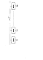
図2は、本発明の実施例1における試験機能付き警報器を用いた警報システムを示す概略の構成図である。
(Constitution)
FIG. 2 is a schematic configuration diagram illustrating an alarm system using an alarm device with a test function according to the first embodiment of the present invention.
この警報システムは、例えば、一般住宅の台所や寝室、居間の他、オフィスの一室等の比較的に小さな監視領域にそれぞれ設置された複数個の試験機能付き警報器1−1〜1−N(但し、Nは2以上の正の整数)を備え、これらの警報器1−1〜1−Nが連動用リード線2によって相互に通信可能にマルチ接続されている。各警報器1−1〜1−Nには、固有のアドレスが付されている。
This alarm system includes, for example, a plurality of alarm devices 1-1 to 1-N having a test function installed in a relatively small monitoring area such as a kitchen, bedroom, living room, and a room in an office. (Where N is a positive integer equal to or greater than 2), and these alarm devices 1-1 to 1-N are multi-connected so as to communicate with each other via the interlocking
このような警報システムにおいて、警報器(例えば、1−1)は、監視領域で発生した異常(例えば、火災やガス漏れ)を検出して警報を行い、アドレス等を付加した警報信号を他の警報器(例えば、1−2〜1−N)へ送信し、一時的又は定期的な機能試験を行い、アドレス等を付加した試験信号を他の警報器(例えば、1−2〜1−N)へ送信し、更に、他の警報器(例えば、1−3)からの外部警報信号や外部試験信号を受信して連動動作を行うようになっている。 In such an alarm system, an alarm device (for example, 1-1) detects an abnormality (for example, fire or gas leak) that has occurred in the monitoring area, issues an alarm, and sends an alarm signal with an address or the like to another alarm signal. Transmit to an alarm device (for example, 1-2 to 1-N), perform a temporary or periodic function test, and send a test signal with an address or the like to another alarm device (for example, 1-2 to 1-N) In addition, an external alarm signal or an external test signal from another alarm device (for example, 1-3) is received to perform an interlocking operation.
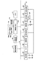
図1は、図2中における本発明の実施例1の各試験機能付き警報器1−1〜1−Nを示す概略の構成図である。 FIG. 1 is a schematic configuration diagram showing each of alarm devices 1-1 to 1-N with a test function according to the first embodiment of the present invention in FIG.
各試験機能付き警報器1(1−1〜1−N)は、同一の構成であり、電池や交流電源から警報器全体の直流駆動電力を出力する電源制御回路11を有し、この電源制御回路11が信号伝送用のバス12に接続されている。バス12には、警報器全体を制御する制御部13が接続されている。制御部13は、検出処理手段、警報処理手段、及び送受信処理手段等の諸機能を実行する制御機能を有し、中央処理装置(以下、「CPU」という。)で構成されるか、或いはカスタムIC(集積回路)やロジック回路等で構成されている。
Each alarm device 1 (1-1 to 1-N) with a test function has the same configuration, and includes a power
制御部13には、スイッチ回路14、設定回路15、クロック発振回路16、及びメモリ17が接続されている。スイッチ回路14は、直流駆動電力等が入力されるノーマリオフ型のスイッチ接点を有する自己復帰型のスイッチ14aを備え、このスイッチ14aに、通電状態を自己保持する自己保持回路が接続されている。自己保持回路は、スイッチ14aのオン状態時の通電状態を自己保持する自己保持素子(例えば、サイリスタ)14bと、このサイリスタ14bのゲートに接続されてゲート電流を供給するターンオン用の抵抗14cとで、構成されている。設定回路15は、動作設定を行うためのディップスイッチ等で構成されている。クロック発振回路16は、制御部13に対して動作用の一定周波数のクロック信号を供給する回路である。メモリ17は、制御部13における処理手順(プログラム)等を記憶する読出し専用メモリ(以下、「ROM」という。)や、各種の閾値やワーキングデータ等を記憶する随時読み書き可能なメモリ(以下、「RAM」という。)等を有している。
A
更に、バス12には、制御部13により制御される検出回路18、音響回路21、表示回路23、送受信手段(例えば、送受信回路)25、計時手段(例えば、タイマ)26、試験手段(例えば、試験回路)27、及び動作検知手段(例えば、動作検知部)28が接続されている。
Further, the
検出回路18は、制御部13内の検出処理手段により制御され、例えば、火災検出センサ19及びガス検出センサ20を駆動すると共に、これらのセンサ19,20の出力をディジタル信号に変換して制御部13に与える回路である。火災検出センサ19は、火災により発生する煙、熱、炎、或いはガス等を所定の周期で検出するものである。火災検出センサ19の具体例としては、発光素子及び受光素子を用いた光電式感知手法、或いは、イオン化式感知手法等を用いて、火災時に発生する煙の濃度を検出し、この検出信号を検出回路18に出力する。ガス検出センサ20は、COガスのガス漏れ発生を所定の周期で検出し、この検出信号を検出回路18に出力する。制御部13内には検出処理手段が設けられ、この検出処理手段が、所定の監視周期で、火災検出センサ19及びガス検出センサ20から検出回路18を介して送られてくる検出結果を、メモリ17内のROMに記憶された閾値と比較し、その検出結果が閾値を超えたときに警報信号を出力する機能を有している。
The
音響回路21は、制御部13内の警報処理手段により制御され、該制御部13内の検出処理手段から送られてくる警報信号や、試験回路27から送られてくる試験信号、或いは制御部13内の送受信処理手段から送られてくる外部警報信号や外部試験信号等に基づき、スピーカやブザー等の音響機器22を駆動し、警報音や音声メッセージを発生させる回路である。表示回路23は、制御部13内の警報処理手段により制御され、該制御部13内の検出処理手段から送られてくる警報信号や、試験回路27から送られてくる試験信号、或いは制御部13内の送受信処理手段から送られてくる外部警報信号や外部試験信号等に基づき、火災警報ランプ、ガス警報ランプ、表示画面等の表示器24を駆動する回路である。これらの音響回路21、音響機器22、表示回路23、表示器24、及び制御部13内の警報処理手段により、警報手段が構成されている。
The
送受信回路25は、制御部13内の送受信処理手段の制御により、連動用リード線25等に対して信号の送受信を行う回路である。制御部13内の送受信処理手段は、該制御部13内の検出処理手段から出力される警報信号や、試験回路27から出力される試験信号にアドレス等の警報情報を付加し、これを送受信回路25から外部へ送信させたり、更に、送受信回路25により受信した警報情報付きの外部警報信号や外部試験信号等をデコードして、音響回路21、及び表示回路23等に所定の処理を行わせるための制御信号を出力するものである。
The transmission /
タイマ26は、繰り返し周期(例えば、24時間又は24時間の倍数)及びこの各周期内における一定の時刻を任意に設定でき、スイッチ14aがオン状態に操作されると、これに応答して計時動作を開始し、各周期において設定された一定の時刻が到来すると時刻信号を出力して制御部13へ与えるものである。試験回路27は、スイッチ14aのオン状態の操作又は時刻信号のいずれか一方に応答して試験信号を制御部13へ出力する回路である。試験信号を入力した制御部13では、検出回路18、音響回路21、表示回路23及び送受信回路25を試験的に動作させて警報を発生させる。動作検知部28は、機能試験時において検出回路18、音響回路21、表示回路23及び送受信回路25が正常に動作したか否かを検知し、この検知結果を制御部13へ送るものであり、例えば、検出回路18の動作確認用の受信機、音響機器22の動作確認用のマイクや振動センサ、表示器24の動作確認用の照度センサ等により構成されている。
The
(動作)
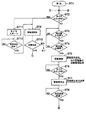
図3は、図1及び図2の監視動作を示すフローチャートである。
(Operation)
FIG. 3 is a flowchart showing the monitoring operation of FIGS. 1 and 2.
(通常の監視動作:ステップST1〜ST8)
電源制御回路11から直流駆動電力が供給され、ステップST1において、監視開始スイッチ等が操作されて警報器1の動作が開始されると、ステップST2において、スイッチ14aがオン状態に操作されたか否かが制御部13で判定される。スイッチ14aがオフ状態のままのときには、メモリ17中のROMに記憶されたプログラムに従い、制御部13による監視動作が開始され、クロック発振回路16から供給されるクロック信号に同期して、検出回路18の駆動制御により所定周期(例えば、数秒間隔)で火災検出センサ19及びガス検出センサ20の検出処理(サンプリング処理)が行われる。ステップST3において、火災発生、或いはガス漏れ発生により、火災検出センサ19、或いはガス検出センサ20によりそれが検出されてその検出値が制御部13内の検出処理手段に入力されると、ステップST4へ進む。
(Normal monitoring operation: steps ST1 to ST8)
When DC drive power is supplied from the power
ステップST4において、制御部13内の検出処理手段により、火災検出センサ19、或いはガス検出センサ20の検出値が、メモリ17中のROMに記憶された閾値と比較される。検出値が閾値よりも小さいときには、ステップST3へ戻り、大きいときには、制御部13内の検出処理手段から警報信号が出力され、ステップST5の警報処理へ進む。
In step ST <b> 4, the detection value of the
ステップST5の警報処理において、制御部13内の検出処理手段から出力された警報信号が該制御部13内の警報処理手段に入力されると、その警報信号の情報(火災発生情報やガス漏れ情報)が処理されて音響回路21や表示回路23が動作し、音響機器22中のブザーからの警報音やスピーカからの音声メッセージ等が出力されたり、表示器24中のランプの点灯又は点滅、或いは表示画面への警報メッセージの表示等が行われる。又、制御部13内の検出処理手段から出力された警報信号が該制御部13内の送受信処理手段に入力されると、その警報信号にアドレスや警報情報が付加され、送受信回路25により連動リード線2を介して他の警報器1へ送出され(例えば、警報器1−1から1−3へ送出され)、他の警報器1−3で所定の連動警報処理が行われる。他の警報器1−3での連動警報処理では、アドレスや警報情報が付加された警報信号が送受信回路(25)で受信され、その警報信号の内容が制御部(13)内の送受信処理手段でデコードされ、該制御部(13)内の警報処理手段、音響回路(21)、表示回路(23)により、音響機器(22)や表示器(24)から連動警報が報知される。
In the alarm processing of step ST5, when the alarm signal output from the detection processing means in the
ステップST5において警報出力が開始された後、ステップST6においてスイッチ14aがオン状態に操作されたか否かが判定される。警報出力の開始後に、スイッチ14aがオン状態に操作されると、このスイッチ14aの入力電流が抵抗14cに流れてサイリスタ14bがターンオンする。すると、スイッチ14aがオフ状態に自己復帰してもサイリスタ14bのオン状態が自己保持され、スイッチ入力電流がそのサイリスタ14bを通して制御部13へ供給される。そして、ステップST7において、制御部13内の警報処理手段から警報停止命令が出力され、表示回路23及び表示器24の動作は継続されるが、音響回路21の動作のみが停止して音響機器22からの音声警報のみが停止する。制御部13内の警報処理手段から出力された警報停止命令は、該制御部13内の送受信処理手段によりアドレス等が付加され、送受信回路25を介して連動リード線2へ送出され、他の警報器1へ送られる。
After the alarm output is started in step ST5, it is determined in step ST6 whether or not the
ステップST7の警報停止後にステップST8へ進み、制御部13内に設けられた時計機能(或いはタイマ26)により、所定時間(例えば、数分)が経過したか否かが判定され、所定時間が経過したときには、結合子2を介してステップST2へ戻り、監視処理が再開される。
After stopping the alarm in step ST7, the process proceeds to step ST8, where it is determined whether or not a predetermined time (for example, several minutes) has elapsed by a clock function (or timer 26) provided in the
(手動による試験動作:ステップST9〜ST10)
ステップST2において、スイッチ14aがオン状態に操作されると、ステップST9へ進み、手動による警報器試験が行われる。即ち、スイッチ14aがオン状態に操作され、その後、該スイッチ14aの接点がオフ状態に自己復帰すると、該スイッチ14aの出力パルス電流が制御部13へ供給され、この制御部13により制御される試験回路27で機能試験が行われる。機能試験では、試験回路27により、例えば、試験信号(火災検出センサ19やガス検出センサ20の検出信号に類似した信号)が生成され、この試験信号に基づいて火災発生やガス漏れ発生の有無が制御部13内の検出処理手段で判断される。
(Manual test operation: steps ST9 to ST10)
In step ST2, when the
ステップST1において、火災又はガス漏れが発生したと判断された場合には、正常に作動し得ることを示す意味で、制御部13内の検出処理手段から試験用の警報信号が出力されて該制御部13内の警報処理手段へ送られ、その試験結果が音響回路21により音響機器22から報知され、或いは表示回路23により表示器24から報知される。この際、動作検知部28により、検出回路18、音響機器22、表示器24、及び送受信回路25が正常に動作したか否かが検知される。検知結果が正常のときには、結合子1を介してステップST2へ戻り、検知結果が異常のときには、つまり警報器1が故障しているときには、その旨が表示器24等から報知され、監視動作が終了する。
In step ST1, when it is determined that a fire or gas leak has occurred, a test alarm signal is output from the detection processing means in the
(タイマによる繰り返し周期動作:ステップST11〜ST12)
ステップST2において、スイッチ14aがオン状態に操作されると、ステップST9において上記の試験動作が行われると共に、ステップST11へ進んでタイマ26の計数動作が開始される。タイマ26には、予め繰り返し周期(例えば、24時間(1日)又は24時間の倍数(日、週、月、年))とこの各周期内における一定時刻(例えば、7時10分)が設定されているので、ステップST12において、タイマ設定時刻が到来したか否かが制御部13で判定される。タイマ設定時刻が到来しているときには、ステップST9へ進んで上記と同様の試験動作が行われる。
(Repetitive cycle operation by timer: steps ST11 to ST12)
In step ST2, when the
(効果)
本実施例1では、次の(1)〜(3)のような効果がある。
(effect)
The first embodiment has the following effects (1) to (3).
(1) タイマ26により、ユーザが任意に定期的な自動試験を行う時刻を設定できるので、ユーザに都合の良い日時に警報器1の自動的試験を行うことができる。その上、毎日又は毎週等の同じ時刻に、音響機器22から音声によるテスト結果が報知(鳴動)されるので、目覚まし時計等の代わりに日常的に利用することができる。
(1) The
(2) 動作検知部28を設けたので、手動による試験時、及びタイマ26による自動定期試験時において、警報発生時に検出回路18、音響機器22、表示器24、及び送受信回路25が確実に機能することを検知できる。その上、動作検知部28による検知結果を表示器24に表示する構成にしておけば、仮にユーザが試験時にいなくても検知結果を後から知ることもできる。
(2) Since the
(3) スイッチ14aは、タイマ開始の他に、警報音停止と手動試験開始とにも使用するので、スイッチの共用化によってスイッチ数を削減でき、構成の簡単化によってコストを低減できる。
(3) Since the
本発明は、上記実施例1に限定されず、種々の変形が可能である。この変形例である実施例2としては、例えば、次の(A)〜(H)のようなものがある。 The present invention is not limited to the first embodiment, and various modifications can be made. As a second embodiment which is this modification, for example, there are the following (A) to (H).
(A) タイマ26を省略し、クロック発振回路16から出力されるクロック信号に基づき時間を計数する計時手段を制御部13内に設けても良い。タイマ26を省略することにより、回路構成を簡略化できる。
(A) The
(B) タイマ26(或いはこれに相当する上記(A)の制御部13内の計時手段)では、繰り返し周期が24時間の値或いは24時間の倍数の値に設定できる構成になっているが、この繰り返し周期を複数設定可能な構成にし、その内に短い周期に基づく時刻信号の出力を停止させる停止手段(例えば、スイッチ14aを利用、或いは新たな停止用のスイッチ)を設けても良い。繰り返し周期を複数設定する場合、例えば、2つのタイマ(或いはこれに相当する制御部13内の2つの計時手段)を設け、周期の短い方を24時間、周期の長い方を30日(24時間×30回)に設定し、24時間の方は目覚まし時計として使用できるようにする。又、目覚まし時計が不要であれば、周期の短い24時間の方は停止手段で停止させるが、周期の長い30日の方は動作しているため、30日に一度は必ず試験が行われるので、警報器1の性能を維持できているか否かを確認でき、使い勝手が良い。
(B) In the timer 26 (or the time measuring means in the
(C) 音響機器22或いは表示器24による警報の内容は、通常の警報時と試験時とで異なる態様にしても良い。例えば、試験時においては、音響機器22から通常とは異なるブザーの鳴動パターンや音量を変化させたり、異なる音声メッセージを再生させたりする。これにより、本警報と試験警報とを区別でき、試験警報時に本警報と間違えて行動することを防止できる。
(C) The content of the alarm by the
(D) 警報器(例えば、1−1)の試験時に、試験用の警報信号を送受信回路25から連動用リード線2を介して他の警報器(例えば、1−2・・・)へ移報し、動作検知部28により、該送受信回路25が正常に動作するか否かを検知する場合、他の警報器1−2,・・・側では、一時的(即ち、パルス的)な試験用警報信号を受信したときには、警報を発生しないようにし、連続的な通常の警報信号を受信したときのみ警報を発するような構成にしても良い。このような構成にすれば、試験時において本警報と間違えて行動することを防止できる。
(D) When testing an alarm device (for example, 1-1), a test alarm signal is transferred from the transmission /
(E) 複数の警報器1−1〜1−Nを連動用リード線2によってマルチ接続したが、電波や赤外線等の無線によりマルチ接続しても良い。この際、それに応じて送受信回路25の構成を変更すれば良い。
(E) Although a plurality of alarm devices 1-1 to 1-N are multi-connected by the interlocking
(F) 試験回路27を省略し、これに代えて外部に設けた外部試験信号出力用の試験装置を送受信回路25に接続し、警報器1の機能試験を行う構成にしても良い。これにより、警報器1の構成を簡素化でき、低コスト化が可能になる。
(F) The
(G) サイリスタ14bを用いてスイッチ14aの通電状態を自己保持する回路構成にしたが、ラッチングリレー等の他の自己保持素子、或いは他の電子部品を用いて自己保持回路を構成しても良い。
(G) Although the circuit configuration is such that the energized state of the
(H) 警報器1(1−1〜1−N)は、マルチ接続しなくても単体でも使用できる。当初から単体専用構造にするのであれば、送受信回路25等を省略でき、これによって構成の簡単化と低コスト化が図れる。
(H) The alarm device 1 (1-1 to 1-N) can be used alone without being multi-connected. If a single-dedicated structure is used from the beginning, the transmission /
(付記1)
付記1に記載の警報器は、ノーマリオフ型のスイッチ接点を有し、オン状態に操作されると前記スイッチ接点がオフ状態からオン状態になった後にオフ状態に自己復帰するスイッチと、繰り返し周期及びこの各周期内における一定の時刻が任意に設定され、前記スイッチがオン状態に操作されると、これに応答して計時動作を開始し、前記各周期において前記一定の時刻が到来すると時刻信号を出力する計時手段と、前記スイッチ接点がオフ状態のときに動作して監視領域で発生した異常を所定の監視周期で検出する検出手段と、前記所定の監視周期で前記検出手段の検出結果を予め定められた閾値と比較し、前記検出結果が前記閾値を超えたときに警報信号を出力する検出処理手段と、前記検出処理手段から出力される前記警報信号に応答して音声や表示により警報を発生し、この警報発生後に前記スイッチがオン状態に操作されると、これに応答して前記警報の内の前記音声を停止する警報手段と、前記スイッチのオン状態の操作又は前記時刻信号のいずれか一方に応答して試験信号を出力し、前記検出手段、前記検出処理手段、及び前記警報手段を試験的に動作させて前記警報手段から警報を発生させて動作確認の試験を行う試験手段と、前記試験時において前記検出手段、及び前記警報手段が正常に動作したか否かを検知する動作検知手段と、を備えたことを特徴とする。
(Appendix 1)
The alarm device according to
(付記2)
付記2に記載の警報器は、付記1に記載の警報器において、前記検出処理手段から出力された前記警報信号を外部へ送信し、且つ、外部から送られてくる外部警報信号や外部試験信号を受信する送受信手段と、前記送受信手段で受信した前記外部警報信号や前記外部試験信号をデコードして前記警報手段、前記試験手段、及び前記動作検知手段に所定の処理を行わせる送受信処理手段とを設け、前記試験手段は、前記送受信処理手段の制御に基づき前記警報手段、及び前記送受信手段を試験的に動作させて前記警報手段から前記警報を発生させると共に前記送受信手段から前記警報信号を送信させて動作確認の試験を行い、
前記動作検知手段は、前記試験時において前記検出手段、前記警報手段、及び前記送受信手段が正常に動作したか否かを検知する構成にしたことを特徴とする。
(Appendix 2)
The alarm device according to
The operation detection unit is configured to detect whether the detection unit, the alarm unit, and the transmission / reception unit operate normally during the test.
(付記3)
付記3に記載の警報器は、付記1又は2に記載の警報器において、前記繰り返し周期は、24時間の値又は24時間の倍数の値に設定可能な構成にしたことを特徴とする。
(Appendix 3)
The alarm device according to attachment 3 is characterized in that in the alarm device according to
(付記4)
付記4に記載の警報器は、付記1〜3のいずれか1つに記載の警報器において、前記繰り返し周期は、複数設定可能な構成にし、その内の短い周期に基づく前記時刻信号の出力を停止させる停止手段を設けたことを特徴とする。
(Appendix 4)
The alarm device according to appendix 4 is the alarm device according to any one of
(付記5)
付記5に記載の警報器は、付記1〜4のいずれか1つに記載の警報器において、前記警報手段から発生する前記警報の内容は、通常の警報時と試験時とで異なる態様にしたことを特徴とする。
(Appendix 5)
The alarm device according to appendix 5 is the alarm device according to any one of
(付記6)
付記6に記載の警報器は、付記2〜5のいずれか1つに記載の警報器において、前記警報手段は、外部から送られてくる前記外部試験信号に対してはそれが連続した場合にのみ前記警報を発する構成にしたことを特徴とする。
(Appendix 6)
The alarm device according to appendix 6 is the alarm device according to any one of
付記1〜4に記載の警報器によれば、1つのスイッチを用いて定期試験用計時手段の開始、手動による試験の開始、又は警報音の停止を行うことができるので、スイッチの共用化による構成の簡単化と低コスト化が可能になる。定期試験用計時手段の周期及び時刻を任意に設定できるので、ユーザの都合の良い時刻に定期試験の警報を発生でき、迷惑にならないばかりか、目覚まし時計代わりに使える。更に、試験手段、及び動作検知手段を設けたので、警報発生時に確実に機能することを試験できる。
According to the alarm devices described in
付記5、6に記載の警報器によれば、試験動作させた場合に、本警報と間違えることを防止できる。 According to the alarm devices described in appendices 5 and 6, when a test operation is performed, it can be prevented from being mistaken for this alarm.
1,1−1〜1−N 警報器
13 制御部
14 スイッチ回路
14a スイッチ
18 検出回路
19 火災検出センサ
20 ガス検出センサ
21 音響回路
22 音響機器
23 表示回路
24 表示器
25 送受信回路
26 タイマ
27 試験回路
28 動作検知部
DESCRIPTION OF
Claims (2)
監視領域で発生した異常を検出する検出手段と、
前記検出手段の検出結果に基づいて異常発生を判別したときに警報信号を出力する検出処理手段と、
前記検出処理手段から出力される前記警報信号に応答して警報を発生する警報手段と、
前記警報手段による警報の停止を指示するスイッチと、
外部と信号の送受信を行う送受信手段と、
前記検出処理手段から前記警報信号が出力された場合に、前記警報手段により警報を発生させ、当該警報の発生中に前記スイッチが操作された場合に、前記警報手段による警報を停止させると共に警報停止命令を前記送受信手段を介して外部に送信する制御手段と、
を備える警報器。 An alarm device that detects an abnormality in the monitoring area and outputs an alarm,
Detection means for detecting an abnormality occurring in the monitoring area;
Detection processing means for outputting an alarm signal when abnormality occurrence is determined based on the detection result of the detection means;
Alarm means for generating an alarm in response to the alarm signal output from the detection processing means;
A switch for instructing to stop the alarm by the alarm means;
A transmission / reception means for transmitting / receiving signals to / from the outside;
When the alarm signal is output from the detection processing means, an alarm is generated by the alarm means, and when the switch is operated during the generation of the alarm, the alarm by the alarm means is stopped and the alarm is stopped. Control means for transmitting an instruction to the outside via the transmission / reception means;
Alarm device with.
請求項1に記載の警報器。 The control means, when the alarm signal is output from the detection processing means, causes the alarm means to generate an alarm and transmits the alarm signal to the outside via the transmission / reception means, and externally via the transmission / reception means. When an alarm signal is received from the above, an alarm is generated by the alarm means.
The alarm device according to claim 1.
Priority Applications (1)
| Application Number | Priority Date | Filing Date | Title |
|---|---|---|---|
| JP2010004244A JP5123957B2 (en) | 2010-01-12 | 2010-01-12 | Alarm |
Applications Claiming Priority (1)
| Application Number | Priority Date | Filing Date | Title |
|---|---|---|---|
| JP2010004244A JP5123957B2 (en) | 2010-01-12 | 2010-01-12 | Alarm |
Related Parent Applications (1)
| Application Number | Title | Priority Date | Filing Date |
|---|---|---|---|
| JP2004210107A Division JP4713854B2 (en) | 2004-07-16 | 2004-07-16 | Alarm |
Publications (3)
| Publication Number | Publication Date |
|---|---|
| JP2010079934A true JP2010079934A (en) | 2010-04-08 |
| JP2010079934A5 JP2010079934A5 (en) | 2010-08-26 |
| JP5123957B2 JP5123957B2 (en) | 2013-01-23 |
Family
ID=42210209
Family Applications (1)
| Application Number | Title | Priority Date | Filing Date |
|---|---|---|---|
| JP2010004244A Expired - Fee Related JP5123957B2 (en) | 2010-01-12 | 2010-01-12 | Alarm |
Country Status (1)
| Country | Link |
|---|---|
| JP (1) | JP5123957B2 (en) |
Citations (4)
| Publication number | Priority date | Publication date | Assignee | Title |
|---|---|---|---|---|
| JPS6165398A (en) * | 1984-09-05 | 1986-04-03 | 三菱電機株式会社 | Home control system |
| JPS61282998A (en) * | 1985-06-07 | 1986-12-13 | 三菱電機株式会社 | Home monitor system |
| JP2000003486A (en) * | 1998-06-12 | 2000-01-07 | Hochiki Corp | Fire alarm system for apartment house |
| JP2002230656A (en) * | 2001-01-30 | 2002-08-16 | Hochiki Corp | Alarm |
-
2010
- 2010-01-12 JP JP2010004244A patent/JP5123957B2/en not_active Expired - Fee Related
Patent Citations (4)
| Publication number | Priority date | Publication date | Assignee | Title |
|---|---|---|---|---|
| JPS6165398A (en) * | 1984-09-05 | 1986-04-03 | 三菱電機株式会社 | Home control system |
| JPS61282998A (en) * | 1985-06-07 | 1986-12-13 | 三菱電機株式会社 | Home monitor system |
| JP2000003486A (en) * | 1998-06-12 | 2000-01-07 | Hochiki Corp | Fire alarm system for apartment house |
| JP2002230656A (en) * | 2001-01-30 | 2002-08-16 | Hochiki Corp | Alarm |
Also Published As
| Publication number | Publication date |
|---|---|
| JP5123957B2 (en) | 2013-01-23 |
Similar Documents
| Publication | Publication Date | Title |
|---|---|---|
| CN111862498B (en) | User interface for event prioritization and hazard detection in smart home environment | |
| US9607494B2 (en) | Supervised interconnect smoke alarm system and method of using same | |
| JP4865263B2 (en) | Fire alarm | |
| US8432277B2 (en) | Alarm device and alarm system | |
| JP5074282B2 (en) | Alarm | |
| WO2009133726A1 (en) | Alarm device | |
| JP4713854B2 (en) | Alarm | |
| JP2013149283A (en) | Alarm | |
| JP3143139U (en) | Alarm | |
| JP3143138U (en) | Alarm | |
| JP2009146232A (en) | Alarm | |
| JP2010286979A (en) | Safety confirmation device | |
| JP5744491B2 (en) | Monitoring system and alarm | |
| JP5266078B2 (en) | Alarm system and alarm | |
| JP5335054B2 (en) | Alarm | |
| JP2010108516A (en) | Alarm device | |
| JP5121855B2 (en) | Alarm | |
| JP5123957B2 (en) | Alarm | |
| JP5744577B2 (en) | Alarm and monitoring system | |
| JP5878707B2 (en) | Monitoring system and alarm | |
| JP4651322B2 (en) | Fire alarm | |
| JP2008040854A (en) | Wireless alarming device | |
| JP5893835B2 (en) | Alarm and monitoring system | |
| JP4944229B2 (en) | Alarm | |
| JP2005284356A (en) | Monitoring device |
Legal Events
| Date | Code | Title | Description |
|---|---|---|---|
| A621 | Written request for application examination |
Free format text: JAPANESE INTERMEDIATE CODE: A621 Effective date: 20100112 |
|
| A521 | Request for written amendment filed |
Free format text: JAPANESE INTERMEDIATE CODE: A523 Effective date: 20100709 |
|
| A131 | Notification of reasons for refusal |
Free format text: JAPANESE INTERMEDIATE CODE: A131 Effective date: 20110615 |
|
| A521 | Request for written amendment filed |
Free format text: JAPANESE INTERMEDIATE CODE: A523 Effective date: 20110811 |
|
| A131 | Notification of reasons for refusal |
Free format text: JAPANESE INTERMEDIATE CODE: A131 Effective date: 20110915 |
|
| A521 | Request for written amendment filed |
Free format text: JAPANESE INTERMEDIATE CODE: A523 Effective date: 20111111 |
|
| A131 | Notification of reasons for refusal |
Free format text: JAPANESE INTERMEDIATE CODE: A131 Effective date: 20120118 |
|
| A521 | Request for written amendment filed |
Free format text: JAPANESE INTERMEDIATE CODE: A523 Effective date: 20120316 |
|
| TRDD | Decision of grant or rejection written | ||
| A01 | Written decision to grant a patent or to grant a registration (utility model) |
Free format text: JAPANESE INTERMEDIATE CODE: A01 Effective date: 20121003 |
|
| A01 | Written decision to grant a patent or to grant a registration (utility model) |
Free format text: JAPANESE INTERMEDIATE CODE: A01 |
|
| A61 | First payment of annual fees (during grant procedure) |
Free format text: JAPANESE INTERMEDIATE CODE: A61 Effective date: 20121026 |
|
| FPAY | Renewal fee payment (event date is renewal date of database) |
Free format text: PAYMENT UNTIL: 20151102 Year of fee payment: 3 |
|
| R150 | Certificate of patent or registration of utility model |
Ref document number: 5123957 Country of ref document: JP Free format text: JAPANESE INTERMEDIATE CODE: R150 Free format text: JAPANESE INTERMEDIATE CODE: R150 |
|
| LAPS | Cancellation because of no payment of annual fees |