JP2010069717A - Inkjet recorder - Google Patents

Inkjet recorder Download PDF

Info

Publication number
JP2010069717A
JP2010069717A JP2008239508A JP2008239508A JP2010069717A JP 2010069717 A JP2010069717 A JP 2010069717A JP 2008239508 A JP2008239508 A JP 2008239508A JP 2008239508 A JP2008239508 A JP 2008239508A JP 2010069717 A JP2010069717 A JP 2010069717A
Authority
JP
Japan
Prior art keywords
blade
cleaner
ink
recording head
blade support
Prior art date
Legal status (The legal status is an assumption and is not a legal conclusion. Google has not performed a legal analysis and makes no representation as to the accuracy of the status listed.)
Granted
Application number
JP2008239508A
Other languages
Japanese (ja)
Other versions
JP5238423B2 (en
Inventor
Masao Shiotani
正夫 塩谷
Current Assignee (The listed assignees may be inaccurate. Google has not performed a legal analysis and makes no representation or warranty as to the accuracy of the list.)
Olympus Corp
Original Assignee
Olympus Corp
Priority date (The priority date is an assumption and is not a legal conclusion. Google has not performed a legal analysis and makes no representation as to the accuracy of the date listed.)
Filing date
Publication date
Application filed by Olympus Corp filed Critical Olympus Corp
Priority to JP2008239508A priority Critical patent/JP5238423B2/en
Publication of JP2010069717A publication Critical patent/JP2010069717A/en
Application granted granted Critical
Publication of JP5238423B2 publication Critical patent/JP5238423B2/en
Active legal-status Critical Current
Anticipated expiration legal-status Critical

Links

Images

Abstract

<P>PROBLEM TO BE SOLVED: To provide an inkjet recorder which restrains ink from flowing over a blade and staining the peripheral part or the like of a recording head, and always provides high-quality image formation. <P>SOLUTION: In the inkjet recorder 1, ink attached to a nozzle plate 11 of a recording head 10 is swept by a blade 21. The blade 21 is supported by a blade supporter 22 and moved by driving of a motor for driving a blade supporter within a predetermined range of the recording head 10 in a longitudinal direction. The ink attached to the blade 21 is absorbed from the blade 21 by abutting on a cleaner 30 arranged to abut on the blade 21. A controller controls the motor for driving the blade supporter so that the portion where the blade 21 abuts on the cleaner 30 is changed each time the blade 21 and the cleaner 30 abut on each other. <P>COPYRIGHT: (C)2010,JPO&INPIT

Description

本発明はインクジェット記録装置に関し、より詳細には、インクジェット記録ヘッドのノズルプレートを清掃するワイピング機構を装備するインクジェット記録装置に関するものである。   The present invention relates to an ink jet recording apparatus, and more particularly to an ink jet recording apparatus equipped with a wiping mechanism for cleaning a nozzle plate of an ink jet recording head.

一般的に普及しているインクジェット記録装置は、記録ヘッドのメンテナンス系を有しており、記録ヘッドのノズルプレートに付着するインクや塵挨を除去することが必須となっている。これは、インクを選択的に噴射して画像を形成するノズル周囲に、インク滴や塵挨が付着していると、噴射したインクが、ノズルから記録メディアに向かって真っ直ぐに飛翔せず、曲がってしまう。そのため、画像に乱れが生じて画像品質を損なってしまうことがある。   Ink jet recording apparatuses that are generally used have a recording head maintenance system, and it is essential to remove ink and dust adhering to the nozzle plate of the recording head. This is because if ink droplets or dust adhere to the periphery of the nozzle that selectively ejects ink to form an image, the ejected ink does not fly straight from the nozzle toward the recording medium, but bends. End up. As a result, the image may be disturbed and the image quality may be impaired.

また、ノズルプレートに付着するインク液滴量が多いと、ノズルプレートに対して近接して搬送される記録メディアにインク液滴が接触して、用紙汚れや画像汚れとなる。そのため、やはり印刷品質を低下させてしまう。   Further, if the amount of ink droplets adhering to the nozzle plate is large, the ink droplets come into contact with the recording medium conveyed in proximity to the nozzle plate, resulting in paper stains or image stains. Therefore, the print quality is also deteriorated.

こうした画像品質の低下を防止するために、記録動作の前後や合間に、ノズルプレートをワイパブレードで拭うことにより、インク液滴や塵挨を除去することが行われている。このワイパブレードは、通常、ゴム等の柔軟性のある剛体や多孔質部材から成るインク吸収体等が用いられる。そして、前記ワイパブレードをノズルプレートに密着させながら移動させることで、インク液滴、塵挨等の除去をすることができるようにしている。   In order to prevent such deterioration in image quality, ink droplets and dust are removed by wiping the nozzle plate with a wiper blade before and after the recording operation. As the wiper blade, a flexible rigid body such as rubber or an ink absorber made of a porous member is usually used. The wiper blade is moved while being in close contact with the nozzle plate, so that ink droplets, dust and the like can be removed.

例えば、下記特許文献1には、印字ヘッドと、印字ヘッドのノズル面をワイピングする非インク吸収性の弾性部材からなるワイパブレードと、ワイパブレードに付着したインクを吸収除去するインク吸収体とを備えたインクジェットプリンタであって、インク吸収体にはワイパブレードの印字ヘッドをワイピングした面と接触する接触面を設け、ワイピングによりワイパブレードにインクが付着した部分がすべてインク吸収体に接触して、ワイパブレードに付着しているインクを吸収除去する旨が記載されている。   For example, Patent Literature 1 below includes a print head, a wiper blade made of a non-ink-absorbing elastic member that wipes the nozzle surface of the print head, and an ink absorber that absorbs and removes ink adhering to the wiper blade. In the ink jet printer, the ink absorber is provided with a contact surface that comes in contact with the surface of the wiper blade on which the print head is wiped. It describes that ink adhering to the blade is absorbed and removed.

また、下記特許文献2には、印字ヘッドと、印字ヘッドのノズル面をワイピングする非インク吸収性の弾性部材からなるワイパブレードと、ワイパブレードに付着したインクを吸収除去するインク吸収体とを備えたインクジェットプリンタであって、インク吸収体にはインク伝達部材を介して排インク吸収体が連結され、インク吸収体によって吸収されたインクを、毛細管現象を利用して、排インク吸収体に伝達させる旨の記載がある。
特開平9−57992号公報 特開平3−293151号公報
Patent Document 2 below includes a print head, a wiper blade made of a non-ink absorbing elastic member that wipes the nozzle surface of the print head, and an ink absorber that absorbs and removes ink adhering to the wiper blade. The ink absorber is connected to the ink absorber via an ink transmission member, and the ink absorbed by the ink absorber is transmitted to the waste ink absorber using capillary action. There is a statement to that effect.
Japanese Patent Laid-Open No. 9-57992 JP-A-3-293151

しかしながら、前述した特許文献1及び2に記載されている構成は、ワイパブレードをクリーナとしてのインク吸収体に当接させて、ワイパブレードに付着しているインクをクリーナに吸収させているが、何れもワイパブレードが当接するクリーナの部位は常に同じとなっている。   However, in the configurations described in Patent Documents 1 and 2 described above, the wiper blade is brought into contact with an ink absorber as a cleaner so that the ink adhering to the wiper blade is absorbed by the cleaner. However, the cleaner part with which the wiper blade contacts is always the same.

このため、ワイパプレードのクリーニングを複数回実行させると、ワイパブレードが常に当接するクリーナの部位は、吸収されたインクですぐに飽和してしまい、クリーニング回数が増加するにつれてワイパブレードに付着しているインクを十分に吸収することができなくなってしまうという課題を有している。   For this reason, when cleaning of the wiper blade is performed a plurality of times, the cleaner portion where the wiper blade always abuts is immediately saturated with the absorbed ink, and the ink adhering to the wiper blade increases as the number of cleanings increases. Has a problem of not being able to absorb the sufficient amount.

したがって本発明は前記実情に鑑みてなされたものであり、その目的は、ワイパブレードが当接するクリーナの部位を順次変化させると共に、吸収インク量が少ないクリーナの部位に対してワイパプレードを当接させることで、複数回にわたってワイパブレードのクリーニング性を良好に保つことができるインクジェット記録装置を提供することである。   Accordingly, the present invention has been made in view of the above circumstances, and an object of the present invention is to sequentially change the site of the cleaner with which the wiper blade contacts, and to bring the wiper blade into contact with the site of the cleaner having a small amount of absorbed ink. Then, it is providing the inkjet recording device which can maintain the cleaning property of a wiper blade favorable several times.

すなわち本発明のインクジェット記録装置は、記録ヘッドのノズルプレートに設けられたノズルから、記録媒体に向けてインクを吐出して画像を記録するインクジェット記録装置に於いて、前記記録ヘッドのノズルプレートに付着したインクを払拭するブレードと、前記記録ヘッドの長手方向に沿った所定の範囲内に於いて、前記プレードを移動させる第1駆動手段と、前記ブレードと当接可能に設置され、前記ブレードと当接することで該ブレードに付着したインクを吸い取るクリーナと、前記第1駆動手段を制御し、前記クリーナに於ける前記ブレードの当接する部位を、前記ブレードが前記クリーナに当接する毎に変更するクリーニング位置変更手段と、を具備することを特徴とする。   That is, the ink jet recording apparatus of the present invention adheres to the nozzle plate of the recording head in the ink jet recording apparatus that records an image by ejecting ink toward the recording medium from the nozzles provided on the nozzle plate of the recording head. A blade for wiping off the ink, a first driving means for moving the blade within a predetermined range along the longitudinal direction of the recording head, and a blade abutting on the blade. A cleaner that sucks ink adhering to the blade by contact, and a cleaning position that controls the first driving means and changes the portion of the cleaner that contacts the blade each time the blade contacts the cleaner. And a changing means.

本発明によれば、ワイパブレードが当接するクリーナの部位を順次変えて、吸収インク量が少ないクリーナの部位に対してワイパプレードを当接させることで、複数回にわたってワイパブレードのクリーニング性を良好に保つことができるインクジェット記録装置を提供することができる。   According to the present invention, the cleaning part of the wiper blade is maintained in good condition over a plurality of times by sequentially changing the cleaner part with which the wiper blade comes into contact and bringing the wiper blade into contact with the part of the cleaner having a small amount of absorbed ink. An ink jet recording apparatus capable of performing the above can be provided.

以下、図面を参照して本発明の実施形態について説明する。   Hereinafter, embodiments of the present invention will be described with reference to the drawings.

(第1の実施形態)
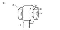
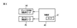
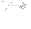
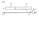
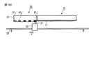
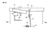
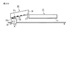
図1は本発明の第1の実施形態に係るインクジェット記録装置1に於ける記録ヘッド10及びワイピング機構20、クリーナ30の概略構成を側面から観た模式図、図2は図1のクリーナ30の斜視図、図3は本インクジェット記録装置に於いてワイパブレードのクリーニングに関する制御系のみ示したブロック構成図である。
(First embodiment)
FIG. 1 is a schematic view of the schematic configuration of the recording head 10, the wiping mechanism 20, and the cleaner 30 in the ink jet recording apparatus 1 according to the first embodiment of the present invention, and FIG. 2 is a schematic view of the cleaner 30 of FIG. FIG. 3 is a block diagram showing only a control system related to cleaning of the wiper blade in the ink jet recording apparatus.

尚、本実施形態に於いては、通常の画像形成装置の構成部、すなわち記録媒体の供給機構、搬送機構、排出機構、画像処理部、制御部、及び他のメンテナンス機構等、は通常の画像形成装置と同じものが搭載されているものとして、その図示及び説明は省略し、本発明の特徴部分であるワイピング機構20と、該ワイピング機構20に関わる記録ヘッド10を図示して説明する。   In this embodiment, components of a normal image forming apparatus, that is, a recording medium supply mechanism, a transport mechanism, a discharge mechanism, an image processing unit, a control unit, and other maintenance mechanisms are used for normal image formation. Since the same apparatus as that of the forming apparatus is mounted, illustration and description thereof will be omitted, and the wiping mechanism 20 which is a characteristic part of the present invention and the recording head 10 related to the wiping mechanism 20 will be illustrated and described.

本実施形態のインクジェット記録装置1に於ける記録ヘッド10は、ピエゾタイプ、若しくはヒータの発熱によるサーマルタイプの何れでも良い。前記記録ヘッド10の形状は、例えば、記録媒体の走行方向と直交する方向(幅方向)に於いて、その記録媒体の幅以上の長さを有している。そして、この記録ヘッド10は、図示されない画像形成装置のフレーム等に固定され、搬送されてノズル前方を通過する記録媒体にインクを吐出して画像を形成する。   The recording head 10 in the ink jet recording apparatus 1 of the present embodiment may be either a piezo type or a thermal type due to heat generated by a heater. The shape of the recording head 10 is, for example, longer than the width of the recording medium in a direction (width direction) orthogonal to the traveling direction of the recording medium. The recording head 10 is fixed to a frame or the like of an image forming apparatus (not shown), and forms an image by ejecting ink onto a recording medium that is transported and passes in front of the nozzles.

また、記録媒体の幅よりは短い短尺記録ヘッドを複数繋ぎ合わせて、記録媒体の幅以上の長さになるように配列しても良い。   Further, a plurality of short recording heads shorter than the width of the recording medium may be connected and arranged so as to have a length equal to or greater than the width of the recording medium.

尚、この記録ヘッドは、固定ヘッドに限定されるものではなく、少量のインクを収納するインクタンクを着脱可能に搭載し、または、インクの充填可能な機能を有するインク室を搭載して、走査移動する走査型記録ヘッドでも適用することも可能である。   The recording head is not limited to a fixed head, and an ink tank that stores a small amount of ink is detachably mounted, or an ink chamber having a function of filling ink is mounted, and scanning is performed. The present invention can also be applied to a moving scanning recording head.

前記ワイピング機構20は、ブレード部21と、それを支持するブレード支持体22と、該ブレード支持体22の移動方向を規制するガイドレール23と、ブレード支持体22に駆動力を与える駆動装置(後述するブレード支持体駆動用モータ44)とから構成される。   The wiping mechanism 20 includes a blade portion 21, a blade support body 22 that supports the blade portion 21, a guide rail 23 that regulates the moving direction of the blade support body 22, and a driving device that applies a driving force to the blade support body 22 (described later). Blade support driving motor 44).

前記ブレード部21は、インク吸収性に富んだ多孔質材料で構成され、ブレード支持部22上に植設される。尚、使用され得る多孔質材料としては、下記のような材料のものが代表的である。或いは、その他、インクとの接液適性が確認できていれば、下記またはそれ以外の材料でも使用可能である。
ポリウレタン
ポリエチレン
クロロプレンゴム
天然ゴム
エチレン・プロピレン(EPDM)ゴム
ニトリルゴム
ブチルゴム
フッ素系
シリコンゴム
EVAゴム(エチレン酢酸ビ二ル共重合体)
また、気孔径は、500μm以下、好ましくは50μm程度である。
The blade portion 21 is made of a porous material rich in ink absorbability and is implanted on the blade support portion 22. As the porous material that can be used, the following materials are typical. Alternatively, the following or other materials can be used as long as the wettability with ink can be confirmed.
Polyurethane
polyethylene
Chloroprene rubber
Natural rubber
Ethylene propylene (EPDM) rubber
Nitrile rubber
Butyl rubber
Fluorine
Silicon rubber
EVA rubber (ethylene vinyl acetate copolymer)
The pore diameter is 500 μm or less, preferably about 50 μm.

ブレード支持部22は、ガイドレール23と係合し、ガイドレール23の延在方向に沿って移動可能に構成され、駆動装置である後述するブレード支持体駆動用モータ44によって、ガイドレール23に沿って移動する。尚、ブレード支持部22のガイドレール23上の移動範囲は、ガイドレール23の両端に設けられたストッパ24a、24b間となっている。そして、ブレード部21がストッパ24aに当て付いている状態がホームポジションであり、ノズルプレート11へのワイピング開始位置である。また、ブレード部21がストッパ24bに当て付いている状態がクリーニングポジションである。   The blade support portion 22 engages with the guide rail 23 and is configured to be movable along the extending direction of the guide rail 23. The blade support portion 22 is moved along the guide rail 23 by a blade support driving motor 44, which will be described later. Move. The range of movement of the blade support 22 on the guide rail 23 is between the stoppers 24 a and 24 b provided at both ends of the guide rail 23. A state where the blade portion 21 is in contact with the stopper 24 a is a home position, and is a position where the wiping to the nozzle plate 11 is started. The state where the blade portion 21 is in contact with the stopper 24b is the cleaning position.

ガイドレール23は、記録ヘッド10のノズル配列方向に沿って延在する軸状である。ガイドレール昇降用モータ45によって、記録ヘッド10に対して近接したワイピング位置と、記録ヘッド10から遠ざかった退避位置、の2つの位置を状況に応じて取り得る(図1は、ワイピング位置を表している)。   The guide rail 23 has a shaft shape extending along the nozzle arrangement direction of the recording head 10. The guide rail raising / lowering motor 45 can take two positions, a wiping position close to the recording head 10 and a retreating position away from the recording head 10 depending on the situation (FIG. 1 shows the wiping position). )

ガイドレール23がワイピング位置、すなわち、ガイドレール23が、より記録ヘッド10に近い位置に位置づけられている状態(図1に示される位置)では、ブレード支持体22上のブレード部21の先端は、記録ヘッド10のノズルプレート11よりも高い位置にあり、オーバーラップしている。これに対して、ガイドレール23が退避位置、すなわち、ガイドレール23が記録ヘッド10から遠ざかった位置に位置づけられている状態では、ブレード支持体22上のブレード部21の先端は、記録ヘッド10のノズルプレート11から離間し、接触しないようになっている。   When the guide rail 23 is in the wiping position, that is, in the state where the guide rail 23 is positioned closer to the recording head 10 (position shown in FIG. 1), the tip of the blade portion 21 on the blade support 22 is It is located higher than the nozzle plate 11 of the recording head 10 and overlaps. On the other hand, in the state where the guide rail 23 is positioned at the retracted position, that is, the position where the guide rail 23 is away from the recording head 10, the tip of the blade portion 21 on the blade support 22 is positioned on the recording head 10. It is separated from the nozzle plate 11 so that it does not come into contact.

ガイドレール23がワイピング位置にある状態で、ブレード支持体駆動用モータ44によってブレード支持体22がガイドレール23に沿って移動されることによって、記録ヘッド10のノズルプレート11等をワイプすることが可能となる。   With the guide rail 23 in the wiping position, the blade support 22 is moved along the guide rail 23 by the blade support driving motor 44, so that the nozzle plate 11 and the like of the recording head 10 can be wiped. It becomes.

また、記録ヘッド10のノズル配列方向の延長線上の、記録ヘッド10の側方であって、ガイドレール23のストッパ24bの上方には、クリーナ30が配設されている。   A cleaner 30 is disposed on the side of the recording head 10 on the extension line in the nozzle arrangement direction of the recording head 10 and above the stopper 24 b of the guide rail 23.

クリーナ30は、ローラ状に成形されたインク吸収体31と、そのインク吸収体31の中心に配設された回転軸32と、当該回転軸32を回転可能に支持する軸受け33とで構成されている。   The cleaner 30 includes an ink absorber 31 formed in a roller shape, a rotary shaft 32 disposed in the center of the ink absorber 31, and a bearing 33 that rotatably supports the rotary shaft 32. Yes.

インク吸収体31は、インク吸収が可能な多孔質部材で構成されており、その平均気孔径がブレード部21の平均気孔径よりも小さいものが選定される。多孔質材料としては、前述したブレード部21と同じ材料候補から選定される。尚、気孔径としては、100μm未満、好ましくは30μm程度が毛細管力の観点から良好である。   The ink absorber 31 is composed of a porous member capable of absorbing ink, and an average pore diameter smaller than the average pore diameter of the blade portion 21 is selected. The porous material is selected from the same material candidates as those of the blade portion 21 described above. The pore diameter is preferably less than 100 μm, preferably about 30 μm from the viewpoint of capillary force.

また、インク吸収体31のガイドレール23側の端部(図1ではインク吸収体31の下端)が、記録ヘッドのノズルプレート11よりもガイドレール23に近接するように、インク吸収体31の形状及び軸受けの高さ位置が設定される。軸32及び軸受け33は、非常に軽い力量であっても軸32が回転できるように、寸法公差や材料が選定されている。   The shape of the ink absorber 31 is such that the end of the ink absorber 31 on the guide rail 23 side (the lower end of the ink absorber 31 in FIG. 1) is closer to the guide rail 23 than the nozzle plate 11 of the recording head. And the height position of the bearing is set. For the shaft 32 and the bearing 33, dimensional tolerances and materials are selected so that the shaft 32 can rotate even with a very light force.

本インクジェット記録装置1のワイパブレードのクリーニングに関する制御系としては、制御部40と、ブレード支持体駆動用モータ44と、ガイドレール昇降用モータ45と、を有して構成される。   The control system for cleaning the wiper blade of the inkjet recording apparatus 1 includes a control unit 40, a blade support driving motor 44, and a guide rail lifting / lowering motor 45.

制御部40は、クリーニング位置変更手段としての機能を有する制御系のみならず、本インクジェット記録装置1全体の制御を司るものである。尚、この制御部40には、タイマー41を有し、後述するように、ブレード支持体22やガイドレール23の駆動制御に利用している。   The control unit 40 controls not only a control system having a function as a cleaning position changing unit but also the entire inkjet recording apparatus 1. The controller 40 has a timer 41, which is used for driving control of the blade support 22 and the guide rail 23, as will be described later.

ブレード支持体駆動用モータ44は、ブレード支持体22をガイドレール23に沿って移動させるための第1駆動手段としての駆動装置である。また、ガイドレール昇降用モータ45は、ブレード支持体22を支持したままのガイドレール23を昇降/下降させるための第2駆動手段としての駆動装置である。これらブレード支持体駆動用モータ44、ガイドレール昇降用モータ45は、制御部40からの指令によって駆動される。   The blade support driving motor 44 is a drive device as first drive means for moving the blade support 22 along the guide rail 23. The guide rail raising / lowering motor 45 is a driving device as second driving means for raising / lowering the guide rail 23 while supporting the blade support 22. The blade support driving motor 44 and the guide rail lifting / lowering motor 45 are driven by a command from the control unit 40.

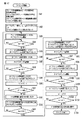
次に、このように構成されたワイピング機構20によって、記録ヘッド10のノズルブレード11をワイピングする動作について、図4A乃至図4I、図6及び図7の動作説明図及び図5のフローチャートを参照して説明する。   Next, regarding the operation of wiping the nozzle blade 11 of the recording head 10 by the wiping mechanism 20 configured as described above, refer to the operation explanatory diagrams of FIGS. 4A to 4I, FIGS. 6 and 7, and the flowchart of FIG. I will explain.

図4Aは、ガイドレール23がワイビング位置に位置づけられ、ブレード支持体22がホームポジションに位置づけられて、これからブレード支持体22が図示矢印A方向に向かって移動し、ワイピングを開始しようとしている直前の状態を示している。そして、ワイピング開始にあたり、ステップS1にて、図6に示されるように、ブレード支持体駆動用モータ44の駆動時間t1、ストッパ24bでのブレード支持体22の停止時間t2、ガイドレール昇降用モータ45の駆動時間t3及びワイピング回数w1が、それぞれ設定される。   FIG. 4A shows a state immediately before the guide rail 23 is positioned at the wiping position, the blade support 22 is positioned at the home position, and the blade support 22 is moved in the direction of the arrow A shown in FIG. Indicates the state. Then, at the start of wiping, in step S1, as shown in FIG. 6, the drive time t1 of the blade support drive motor 44, the stop time t2 of the blade support 22 at the stopper 24b, and the guide rail lifting motor 45 The driving time t3 and the number of times of wiping w1 are set.

次いで、ステップS2にて、ワイピング方向のブレード移動時間に関するタイマカウント値tw、ストッパ24bの位置での停止時間に関するタイマカウント値ts、ガイドレールの昇降時間に関するタイマカウント値tgがそれぞれリセットされると共に、ワイピング回数カウント値wがリセットされる。そして、ステップS3にて、ブレード支持体駆動用モータ44がオンされて、タイマカウント(tw)が開始される。これにより、ブレード支持体22が図示矢印A方向に移動開始され、ワイピングが開始される。   Next, in step S2, the timer count value tw relating to the blade movement time in the wiping direction, the timer count value ts relating to the stop time at the position of the stopper 24b, and the timer count value tg relating to the raising / lowering time of the guide rail are reset, respectively. The wiping count value w is reset. In step S3, the blade support driving motor 44 is turned on, and the timer count (tw) is started. As a result, the blade support 22 starts to move in the direction indicated by the arrow A, and wiping is started.

図4Bは、ワイピング途中のワイピング機構20と記録ヘッド10の状態を模式化した図である。   FIG. 4B is a diagram schematically showing the state of the wiping mechanism 20 and the recording head 10 during wiping.

前述したように、ブレード支持体駆動用モータ44の駆動により、ブレード支持体22に駆動力が与えられ、該ブレード支持体22はガイドレール23に沿って矢印A方向に移動される。そして、ブレード部21がノズルプレート11面上に接触し、ノズルプレート11上に付着しているインク滴が毛細管現象によって吸収されながら、ブレード支持体22が矢印A方向に移動される。   As described above, driving force is applied to the blade support 22 by driving the blade support driving motor 44, and the blade support 22 is moved along the guide rail 23 in the direction of arrow A. Then, the blade portion 21 comes into contact with the surface of the nozzle plate 11, and the blade support 22 is moved in the direction of arrow A while the ink droplets adhering to the nozzle plate 11 are absorbed by the capillary phenomenon.

ここで、記録ヘッド10の右側は、まだワイプされていない状態を示したものである。図4A及び4Bに於いては、記録ヘッド10に、図示されないインク経路を介して圧力を加える等により、ノズルから吐出されパージ液滴13としてノズルプレート11に垂れ下がっている状態を示している。このパージ液滴13は、ブレード部21に接触した瞬間、気孔径大の多孔質材料のブレード部21に吸収され、その内部に浸透されていく。   Here, the right side of the recording head 10 shows a state where it has not been wiped yet. 4A and 4B show a state in which pressure is applied to the recording head 10 via an ink path (not shown) and the ink is ejected from the nozzles and dropped as the purge droplets 13 on the nozzle plate 11. As soon as the purge liquid droplet 13 comes into contact with the blade portion 21, the purge droplet 13 is absorbed by the blade portion 21 of the porous material having a large pore diameter and penetrates into the inside thereof.

図4Cは、ノズルプレート11面上のワイピングが終了し、ブレード部21が記録ヘッド10とクリーナ30との間に位置づけられている状態を示した模式図である。ブレード部21には、ノズルプレート11との接触によってインクが吸収される。この吸収されたインクがクリーナ30によって除去されるために、ブレード支持体22は、この状態から更に図示矢印A方向に向けて移動される。   FIG. 4C is a schematic diagram illustrating a state in which wiping on the surface of the nozzle plate 11 is completed and the blade portion 21 is positioned between the recording head 10 and the cleaner 30. The blade portion 21 absorbs ink by contact with the nozzle plate 11. Since the absorbed ink is removed by the cleaner 30, the blade support 22 is further moved from this state in the direction of the arrow A in the figure.

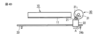
図4Dは、ブレード部21がクリーナ30のインク吸収体31に当接し、ブレード部21が湾曲して、更に図示矢印A方向に向かって移動しようとしている状態を示す模式図である。   FIG. 4D is a schematic diagram showing a state in which the blade portion 21 is in contact with the ink absorber 31 of the cleaner 30, the blade portion 21 is curved, and is about to move further in the illustrated arrow A direction.

ブレード部21がインク吸収体31に当接することで、毛細管現象によって、ブレード部21の多孔質の気孔内に抱えられていたインクを、インク吸収体31の多孔質の気孔内へと伝達させることができる。更に、インク吸収体31にブレード部21が押し当てられることで、ブレード部21は湾曲の度合いが徐々に大きくされる。   By bringing the blade portion 21 into contact with the ink absorber 31, the ink held in the porous pores of the blade portion 21 is transmitted into the porous pores of the ink absorber 31 by capillary action. Can do. Further, when the blade portion 21 is pressed against the ink absorber 31, the degree of curvature of the blade portion 21 is gradually increased.

このとき、ブレード支持体22は、図示矢印A方向に移動しているので、ブレード部21とインク吸収体31との密着度は徐々に強くなる。すると、ブレード支持体22の矢印A方向の移動する力が、インク吸収体31を図示矢印p方向に回動させる力として、インク吸収体31に伝達される。その結果、ブレード支持体22の移動に伴い、インク吸収体31が、図示矢印p方向に回動することになる。   At this time, since the blade support 22 has moved in the direction of the arrow A in the drawing, the degree of adhesion between the blade portion 21 and the ink absorber 31 gradually increases. Then, the moving force of the blade support 22 in the direction of arrow A is transmitted to the ink absorber 31 as a force for rotating the ink absorber 31 in the direction of the arrow p in the figure. As a result, the ink absorber 31 rotates in the direction indicated by the arrow p as the blade support 22 moves.

インク吸収体31は、ブレード部21の多孔質材料よりもその気孔径が小さい。このため、毛細管力がブレード部21のそれよりも大きく、ブレード部21に吸収されていたインクを十分に吸収することが可能となる。   The ink absorber 31 has a pore diameter smaller than that of the porous material of the blade portion 21. For this reason, the capillary force is larger than that of the blade portion 21, and the ink absorbed by the blade portion 21 can be sufficiently absorbed.

図4Eは、ブレード支持体22がストッパ24bに当接され、図示矢印A方向の移動が停止された状態を示す模式図である。   FIG. 4E is a schematic view showing a state in which the blade support 22 is brought into contact with the stopper 24b and the movement in the direction of the arrow A is stopped.

ところで、図4A乃至図4Dに示されるワイピングの間、ステップS4に於いて、タイマカウント値twが監視されてブレード支持体駆動用モータ44の駆動時間t1に到達したか否かが判定される。その結果、タイマカウント値twが前記駆動時間t1に到達したならば、ステップS5に移行して、ブレード支持体駆動用モータ44がオフにされて、タイマカウントtwが終了及びリセットされる。この時点ですでに、ブレード部21は、インク吸収体31と当接し、インク吸収体31は回動し終わっている。   By the way, during the wiping shown in FIGS. 4A to 4D, in step S4, the timer count value tw is monitored to determine whether or not the driving time t1 of the blade support driving motor 44 has been reached. As a result, when the timer count value tw reaches the drive time t1, the process proceeds to step S5, the blade support driving motor 44 is turned off, and the timer count tw is ended and reset. At this time, the blade portion 21 has already been in contact with the ink absorber 31, and the ink absorber 31 has finished rotating.

すると、ブレード支持体22の移動停止に伴い、インク吸収体31の矢印p方向の回動も停止する。このとき、ブレード部21はインク吸収体31との当接により、最も強くインク吸収体31に押しつけられ、内部に抱えているインクがインク吸収体31に向けて伝達される。   Then, as the movement of the blade support 22 stops, the rotation of the ink absorber 31 in the arrow p direction also stops. At this time, the blade portion 21 is most strongly pressed against the ink absorber 31 by contact with the ink absorber 31, and the ink held inside is transmitted toward the ink absorber 31.

尚、インク吸収体31としては、ブレード部21が当接し始めてからブレード支持体22の移動が停止するまで、ブレード部21との当接部位は常に同じであり、その当接部位にてブレード部21からインクが吸収される。そして、その当接部位は、インク吸収体31の矢印p方向の回動により、徐々に矢印p方向に向かって移動されて、この図4Eに示される位置で回動が停止され、ブレード部21に付着されたインクを、十分にクリーナ30に伝達させるために、この状態が所定時間だけ維持される。つまり、ブレード部21をクリーナ30に当接した状態で停止させるために、ステップS6にて、その停止時間のカウントtsが開始される。   As the ink absorber 31, the contact portion with the blade portion 21 is always the same until the movement of the blade support 22 stops after the blade portion 21 starts to contact, 21 absorbs ink. Then, the contact portion is gradually moved in the direction of the arrow p by the rotation of the ink absorber 31 in the direction of the arrow p, and the rotation is stopped at the position shown in FIG. This state is maintained for a predetermined time in order to sufficiently transfer the ink adhered to the cleaner 30 to the cleaner 30. That is, in order to stop the blade part 21 in a state where it is in contact with the cleaner 30, the stop time count ts is started in step S6.

そして、ステップS7に於いて、タイマカウント値tsが監視されてブレード支持体22の停止時間t2に到達したか否かが判定される。その結果、タイマカウント値tsが前記停止時間t2に到達したならば、ステップS8に移行して、タイマカウントtsが終了及びリセットされて、ガイドレール昇降用モータ45がオンにされる。これにより、ガイドレール23が下降される。   In step S7, the timer count value ts is monitored to determine whether or not the stop time t2 of the blade support 22 has been reached. As a result, if the timer count value ts has reached the stop time t2, the process proceeds to step S8, where the timer count ts is ended and reset, and the guide rail raising / lowering motor 45 is turned on. Thereby, the guide rail 23 is lowered.

図4Fは、ブレード支持体22を支持しているガイドレール23を、記録ヘッド10から遠ざかるように、図示矢印B方向に移動させ、ブレード部21をインク吸収体31から離間させた状態を示す模式図である。   FIG. 4F is a schematic view showing a state where the guide rail 23 supporting the blade support 22 is moved in the direction of the arrow B so as to move away from the recording head 10 and the blade portion 21 is separated from the ink absorber 31. FIG.

ノズルプレート11のワイピング及びブレード部21のクリーニングが終了したならば(実際には、前述した所定時間経過したならば)、ガイドレール23が矢印B方向に向けて移動(下降)される。ガイドレール23の下降に伴い、ガイドレール23に係合しているブレード支持体22及びブレード部21も共に下降され、ブレード部21がインク吸収体31から離間される。   When the wiping of the nozzle plate 11 and the cleaning of the blade portion 21 are completed (in practice, when the above-described predetermined time has elapsed), the guide rail 23 is moved (lowered) in the direction of arrow B. As the guide rail 23 is lowered, the blade support 22 and the blade portion 21 engaged with the guide rail 23 are also lowered, and the blade portion 21 is separated from the ink absorber 31.

ブレード部21が下降している過程(密着している状態から離間するまで)に於いて、インク吸収体31は回転しない、若しくは僅かに矢印p方向に回動するが、ブレード部21が離間した後は回動しない。   In the process in which the blade portion 21 is descending (from the close contact state to the separation), the ink absorber 31 does not rotate or slightly rotates in the direction of the arrow p, but the blade portion 21 is separated. After that it does not rotate.

インク吸収体31は、ブレード部21が離間した後は、完全に回動を停止してその状態を維持する。つまり、ブレード部21のクリーニング前後では、インク吸収体31は、矢印p方向に回動すると共に、ブレード部21と当接した部位、すなわち、インクを吸収した部位311 も、矢印p方向に移動したことになる。 After the blade part 21 is separated, the ink absorber 31 completely stops rotating and maintains its state. That is, before and after the cleaning of the blade part 21, the ink absorber 31 rotates in the direction of the arrow p, and the part in contact with the blade part 21, that is, the part 31 1 that has absorbed the ink also moves in the direction of the arrow p. It will be done.

そして、ステップS9にて、タイマカウント(tg)が開始される。更に、ステップS10に於いて、タイマカウント値tgが監視されてガイドレール昇降用モータ45の駆動時間t3に到達したか否かが判定される。その結果、タイマカウント値tgが前記駆動時間t3に到達したならば、ステップS11に移行して、ガイドレール昇降用モータ45がオフにされ、タイマカウントtgが終了すると共にリセットされる。つまり、ガイドレール23の下降が停止される。このとき、ブレード部21は、クリーナ30のインク吸収体31から離間された状態となる。   In step S9, a timer count (tg) is started. Further, in step S10, the timer count value tg is monitored to determine whether or not the driving time t3 of the guide rail raising / lowering motor 45 has been reached. As a result, if the timer count value tg reaches the driving time t3, the process proceeds to step S11, where the guide rail raising / lowering motor 45 is turned off, and the timer count tg ends and is reset. That is, the lowering of the guide rail 23 is stopped. At this time, the blade portion 21 is separated from the ink absorber 31 of the cleaner 30.

次に、ステップS12にて、ブレード支持体駆動用モータ44が逆方向に駆動されるべくオンされ、タイマカウントtwが開始される。これにより、ブレード支持体22が、図4Gの矢印C方向に移動開始される。そして、続くステップS13に於いて、タイマカウント値twが監視されてブレード支持体駆動用モータ44の駆動時間t1に到達したか否かが判定される。その結果、タイマカウント値twが前記駆動時間t1に到達したならば、ステップS14に移行して、ブレード支持体駆動用モータ44がオフにされて、タイマカウントtwが終了及びリセットされる。更に、ガイドレール昇降用モータ45が逆方向に駆動されるべくオンされる。   
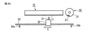
Next, in step S12, the blade support driving motor 44 is turned on to be driven in the reverse direction, and the timer count tw is started. As a result, the blade support 22 starts to move in the direction of arrow C in FIG. 4G. In subsequent step S13, the timer count value tw is monitored to determine whether or not the driving time t1 of the blade support driving motor 44 has been reached. As a result, if the timer count value tw reaches the drive time t1, the process proceeds to step S14, the blade support driving motor 44 is turned off, and the timer count tw is ended and reset. Further, the guide rail raising / lowering motor 45 is turned on to be driven in the reverse direction.

図4Gは、ブレード支持体22をガイドレール23上のホームポジションに戻すべく、図示矢印C方向に向けて移動させている状態を示す模式図である。   FIG. 4G is a schematic diagram showing a state where the blade support 22 is moved in the direction of the arrow C in order to return the blade support 22 to the home position on the guide rail 23.

前述したように、ガイドレール23の下降が完了したならば、ブレード支持体駆動用モータ44によってブレード支持体22が矢印C方向に移動される。ノズルプレート11の高さは、インク吸収体31の下端よりも高い位置にあるため、矢印C方向に移動している間、ブレード部21はノズルプレート11に当接しない。そして、ブレード支持体22がストッパ24aに対して当接したならば、ブレード支持体22の矢印C方向への移動が停止される。   As described above, when the lowering of the guide rail 23 is completed, the blade support 22 is moved in the direction of arrow C by the blade support drive motor 44. Since the height of the nozzle plate 11 is higher than the lower end of the ink absorber 31, the blade portion 21 does not contact the nozzle plate 11 while moving in the arrow C direction. When the blade support 22 comes into contact with the stopper 24a, the movement of the blade support 22 in the direction of arrow C is stopped.

次に、ステップS15にて、ガイドレール23を上昇させるべく、タイマカウント(tg)が開始される。そして、ステップS16に於いて、タイマカウント値tgが監視されてガイドレール昇降用モータ45の駆動時間t3に到達したか否かが判定される。その結果、タイマカウント値tgが前記駆動時間t3に到達したならば、ステップS17に移行して、ガイドレール昇降用モータ45がオフにされ、タイマカウントtgが終了すると共にリセットされる。つまり、ガイドレール23の上昇が停止される。   Next, in step S15, a timer count (tg) is started to raise the guide rail 23. In step S16, the timer count value tg is monitored to determine whether or not the driving time t3 of the guide rail raising / lowering motor 45 has been reached. As a result, if the timer count value tg reaches the drive time t3, the process proceeds to step S17, where the guide rail raising / lowering motor 45 is turned off, and the timer count tg ends and is reset. That is, the raising of the guide rail 23 is stopped.

その後、ステップS18にてワイピング回数w1がインクリメントされる。そして、ステップS19に於いて、所定のワイピング回数wに到達したか否かが判定される。ここで、まだ所定のワイピング回数wに到達していなければ、前記ステップS3に移行して、前述した処理動作が繰り返される。一方、所定のワイピング回数wに到達したならば、ワイピングの動作が終了する。   Thereafter, the number of wiping operations w1 is incremented in step S18. In step S19, it is determined whether or not a predetermined wiping count w has been reached. If the predetermined wiping count w has not yet been reached, the process proceeds to step S3 and the above-described processing operation is repeated. On the other hand, when the predetermined wiping count w is reached, the wiping operation ends.

こうして、次回以降、記録ヘッド10のワイピング動作及びブレード部21のクリーニング動作が行われると、図4H及び図7に示されるように、ブレード部21がインク吸収体31に当接する範囲352 、インク吸収体31に於けるインクを吸収した部位312 が、前回のクリーニング時の各部位351 、311 とは異なり、インクの吸収能力がまだ十分にある部位がブレード部21と当接することになる。 Thus, when the wiping operation of the recording head 10 and the cleaning operation of the blade portion 21 are performed after the next time, as shown in FIGS. 4H and 7, the range 35 2 where the blade portion 21 abuts on the ink absorber 31, Unlike the portions 35 1 and 31 1 in the previous cleaning, the portion 31 2 that has absorbed ink in the absorber 31 is in contact with the blade portion 21 at a portion that still has sufficient ink absorption capability. Become.

したがって、本実施形態によれば、ブレード部21のクリーニング動作を実施する際に、ブレードは常にインク吸収体31の異なる部位(インク吸収能力が高い部位)に対して当接することになるので、良好なクリーニング特性を長期間に亘って維持することが可能となる。   Therefore, according to the present embodiment, when the cleaning operation of the blade portion 21 is performed, the blade always comes into contact with different parts of the ink absorber 31 (parts having high ink absorption capability). It becomes possible to maintain a good cleaning characteristic over a long period of time.

尚、本実施形態によれば、ブレード部の気孔径よりもインク吸収体の気孔径の方を大きくしたことにより、より良好なクリーニング特性を引き出すことが可能となる。   According to the present embodiment, it is possible to bring out better cleaning characteristics by making the pore diameter of the ink absorber larger than the pore diameter of the blade portion.

また、本実施形態によれば、ブレード部と当接する部位を変化させるためにインク吸収体を回動させているが、ブレード部を押し当てるだけでインク吸収体を回動させているので、余計な駆動機構が設ける必要がなく、小型化、低コスト化に寄与することができる。   Further, according to the present embodiment, the ink absorber is rotated in order to change the portion that comes into contact with the blade portion. However, the ink absorber is rotated only by pressing the blade portion. There is no need to provide a separate drive mechanism, which can contribute to size reduction and cost reduction.

(第1の実施形態の変形例)
次に、本発明の第1の実施形態に於ける変形例について説明する。
(Modification of the first embodiment)
Next, a modification in the first embodiment of the present invention will be described.

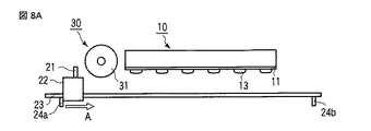
図8A乃至図8Dは、本発明の第1の実施形態の変形例に於ける、ワイピング機構の動作を説明するための図である。   8A to 8D are diagrams for explaining the operation of the wiping mechanism in the modification of the first embodiment of the present invention.

尚、以下に述べる実施形態及び変形例に於いて、インクジェット記録装置の基本的な構成及び動作については、前述した第1の実施形態と同じであるので、説明の重複を避けるため、同一の部分には同一の参照番号を付して、その図示及び説明を省略し、主として異なる部分についてのみ説明する。   In the embodiments and modifications described below, the basic configuration and operation of the ink jet recording apparatus are the same as those in the first embodiment described above, and therefore the same parts are avoided to avoid duplication of explanation. Are denoted by the same reference numerals, illustration and description thereof are omitted, and only different portions will be mainly described.

この変形例が前述した第1の実施形態と異なるのは、クリーナ30がブレード支持体22のホームポジションと記録ヘッド10の間に配置されている点である。   This modification is different from the first embodiment described above in that the cleaner 30 is disposed between the home position of the blade support 22 and the recording head 10.

図8Aは、ガイドレール23がワイビング位置に位置づけられ、ブレード支持体22がホームポジションに位置づけられて、これからブレード支持体22が図示矢印A方向に向かって移動し、ワイピングを開始しようとしている直前の状態を示している。ワイピング開始時の状態では、ブレード部21は、クリーナ30の吸収体31と当接してもインクの吸収はなされない。したがって、前述した第1の実施形態と同様に、図8Bに示されるように、図示矢印A方向に向かってブレード支持体22が移動され、ノズルプレート11上のインク滴が吸収される。   FIG. 8A shows that the guide rail 23 is positioned at the wiping position, the blade support 22 is positioned at the home position, and the blade support 22 is moved in the direction of the arrow A in FIG. Indicates the state. In the state at the start of wiping, the blade portion 21 does not absorb ink even if it comes into contact with the absorber 31 of the cleaner 30. Therefore, as in the first embodiment described above, as shown in FIG. 8B, the blade support 22 is moved in the direction indicated by the arrow A, and the ink droplets on the nozzle plate 11 are absorbed.

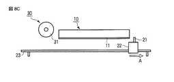
図8Cは、ノズルプレートのワイピングが終了して、クリーナ30に当接する直前のブレード支持体22の状態を示した模式図である。このときは、まだブレード支持部22がクリーナ30に当接していないため、クリーナ30は何ら変位しない。ブレード支持体22は、このときもまだA方向に向かって移動中である。   FIG. 8C is a schematic diagram illustrating a state of the blade support 22 immediately before the nozzle plate wiping is finished and just before contacting the cleaner 30. At this time, since the blade support portion 22 is not yet in contact with the cleaner 30, the cleaner 30 is not displaced at all. The blade support 22 is still moving in the A direction at this time.

図8Dは、ブレード支持体22がクリーナ30に当接し、更に、ブレード支持体22がA方向に向かって移動中であることを示した模式図である。   FIG. 8D is a schematic diagram showing that the blade support 22 is in contact with the cleaner 30 and that the blade support 22 is moving in the A direction.

この場合、ブレード支持体22は、クリーナ30へ当接(密着)しながらの移動に伴い、クリーナ30がブレード支持体22との摩擦により図示矢印p方向に回動する。尚、クリーナ30は、ブレード支持体22と密着している間、ブレード部21に付着または吸収しているインクを吸収する。   In this case, as the blade support 22 moves while abutting (adhering) to the cleaner 30, the cleaner 30 rotates in the direction indicated by the arrow p due to friction with the blade support 22. The cleaner 30 absorbs ink adhering or absorbing to the blade portion 21 while in close contact with the blade support 22.

そして、次回以降のクリーニング動作時には、ブレード部21がインク吸収体31に当接することで、毛細管現象によって、ブレード部21の多孔質の気孔内に抱えられていたインクが、インク吸収体31の多孔質の気孔内へと伝達させることができる。このとき、ブレード支持体22が、図示矢印A方向に移動しているので、ブレード支持体22の矢印A方向の移動する力が、インク吸収体31を図示矢印p方向に回動させる力として、インク吸収体31に伝達される。その結果、ブレード支持体22の移動に伴い、インク吸収体31が、図示矢印p方向に所定量、回動することになる。   In the next and subsequent cleaning operations, the blade portion 21 comes into contact with the ink absorber 31, so that the ink held in the porous pores of the blade portion 21 by the capillary phenomenon is perforated by the ink absorber 31. Can be transmitted into quality pores. At this time, since the blade support 22 is moved in the direction of the arrow A in the figure, the force that moves the blade support 22 in the direction of the arrow A is the force that rotates the ink absorber 31 in the direction of the arrow p in the figure. It is transmitted to the ink absorber 31. As a result, as the blade support 22 moves, the ink absorber 31 rotates by a predetermined amount in the direction indicated by the arrow p.

このように構成することにより、ブレード部21のクリーニング動作を実施する際に、ノズルプレート11面に接触する前に、ブレード部21は常にインク吸収体31の異なる部位に対して当接することになる。したがって、本変形例に於いても、前述した第1の実施形態と同様に、良好なクリーニング特性を長期間に亘って維持することが可能となる。   With this configuration, when performing the cleaning operation of the blade portion 21, the blade portion 21 always abuts against different parts of the ink absorber 31 before contacting the surface of the nozzle plate 11. . Therefore, also in this modification, it is possible to maintain good cleaning characteristics over a long period of time, as in the first embodiment described above.

(第2の実施形態)
次に、本発明の第2の実施形態について説明する。
(Second Embodiment)
Next, a second embodiment of the present invention will be described.

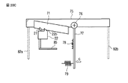
前述した第1の実施形態は、クリーナを回動させることによって、ブレード部がインク吸収体の異なる部位に対して当接するようにしているが、これに限られるものではない。本発明の第2の実施形態では、ブレード部の停止位置をクリーニング毎に延ばしていく(順次右側にずらしていく)ようにしている。   In the first embodiment described above, the blade is brought into contact with a different part of the ink absorber by rotating the cleaner. However, the present invention is not limited to this. In the second embodiment of the present invention, the stop position of the blade portion is extended for each cleaning (sequentially shifted to the right).

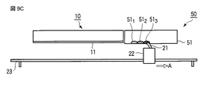
図9A乃至図9Dは、本発明の第2の実施形態に於けるインクジェット記録装置のワイピング機構の動作を説明するための図、図10は第2の実施形態に於けるインクジェット記録装置のワイピングの動作を説明するためのフローチャート、図11は第2の実施形態に於けるワイピングの動作を説明するための図である。   9A to 9D are diagrams for explaining the operation of the wiping mechanism of the ink jet recording apparatus according to the second embodiment of the present invention. FIG. 10 is a diagram illustrating the wiping of the ink jet recording apparatus according to the second embodiment. FIG. 11 is a flowchart for explaining the operation, and FIG. 11 is a diagram for explaining the wiping operation in the second embodiment.

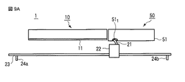
本第2の実施形態に於いて、クリーナ50は、記録ヘッド10に隣接し、且つブレード移動方向の延長上に配設されたインク吸収体51を有して構成される。また、インク吸収体51のブレード部21と当接する面は、ノズルプレート11の下面よりも僅かに低く配置される。   In the second embodiment, the cleaner 50 includes an ink absorber 51 that is adjacent to the recording head 10 and disposed on an extension in the blade movement direction. Further, the surface of the ink absorber 51 that contacts the blade portion 21 is disposed slightly lower than the lower surface of the nozzle plate 11.

次に、このように構成されたワイピング機構によって、記録ヘッド10のノズルブレード11をワイピングする動作について、図9A乃至図9D、図11の動作説明図及び図10のフローチャートを参照して説明する。   Next, an operation of wiping the nozzle blade 11 of the recording head 10 by the wiping mechanism configured as described above will be described with reference to FIGS. 9A to 9D, operation explanatory diagrams of FIG. 11, and a flowchart of FIG.

尚、図10のフローチャートに於けるステップS22〜S23、S25〜S32、S34〜S37、及びステップS39〜S40は、図5のフローチャートのステップS2〜S3、S5〜S12、S14〜S17、及びステップS18〜S19と同様の処理を行うので、それぞれ対応するステップ番号を参照して、ここでは説明は省略する。   Note that steps S22 to S23, S25 to S32, S34 to S37, and steps S39 to S40 in the flowchart of FIG. 10 are steps S2 to S3, S5 to S12, S14 to S17, and step S18 of the flowchart of FIG. Since the same processing as in S19 is performed, the corresponding step number is referred to and the description thereof is omitted here.

ワイピング開始にあたり、ステップS21にて、図11に示されるように、ブレード支持体駆動用モータ44の駆動時間初期値t11、ストッパ24bでのブレード支持体22の停止時間t2、ガイドレール昇降用モータ45の駆動時間t3及びワイピング回数w1が、それぞれ設定される。   At the start of wiping, as shown in FIG. 11, in step S21, as shown in FIG. 11, the driving time initial value t11 of the blade support motor 44, the stop time t2 of the blade support 22 at the stopper 24b, the guide rail lifting motor 45 The driving time t3 and the number of times of wiping w1 are set.

次いで、ステップS22にて、タイマカウント値tw、ts、tgがそれぞれリセットされると共に、ワイピング回数カウント値wがリセットされ、続くステップS23にて、ブレード支持体駆動用モータ44がオンされて、タイマカウント(tw)が開始される。これにより、ブレード支持体22が図示矢印A方向に移動開始され、ワイピングが開始される。   Next, in step S22, the timer count values tw, ts, and tg are reset, and the wiping count value w is reset. In step S23, the blade support driving motor 44 is turned on, and the timer Counting (tw) is started. As a result, the blade support 22 starts to move in the direction indicated by the arrow A, and wiping is started.

図9Aは、ブレード部21が図示矢印A方向に向かって移動し、1回目の停止位置である、クリーナ50のインク吸収体51の下面の一端部(左端)に当接した状態を示す模式図である。このように、ブレード部21がインク吸収体31に当接することで、毛細管現象によって、ブレード部21の多孔質の気孔内に抱えられていたインクを、インク吸収体31の多孔質の気孔内へと伝達させることができる。   FIG. 9A is a schematic diagram showing a state in which the blade portion 21 moves in the direction of the arrow A and is in contact with one end (left end) of the lower surface of the ink absorber 51 of the cleaner 50, which is the first stop position. It is. In this way, when the blade portion 21 abuts on the ink absorber 31, the ink held in the porous pores of the blade portion 21 is brought into the porous pores of the ink absorber 31 by capillary action. Can be communicated.

また、ワイピングの間、ステップS24に於いて、タイマカウント値twが監視されてブレード支持体駆動用モータ44の駆動時間初期値t11に到達したか否かが判定される。その結果、タイマカウント値twが前記駆動時間初期値t11に到達したならば、ステップS25に移行して、ブレード支持体駆動用モータ44がオフにされて、タイマカウントtwが終了及びリセットされる。これにより、ブレード支持体22の矢印A方向への移動が停止され、インク吸収体51の端部のインク吸収能力の高い部位511 にブレード部21を当接させることができる。 During wiping, in step S24, the timer count value tw is monitored to determine whether or not the blade support driving motor 44 driving time initial value t11 has been reached. As a result, if the timer count value tw reaches the drive time initial value t11, the process proceeds to step S25, the blade support driving motor 44 is turned off, and the timer count tw is ended and reset. Thereby, the movement of the blade support 22 in the direction of the arrow A is stopped, and the blade portion 21 can be brought into contact with the portion 51 1 having a high ink absorption capability at the end of the ink absorber 51.

次いで、ステップS26〜S32に於いて、ガイドレール23が下降されてブレード支持体22がホームポジション側に移動される。そして、ステップS33にてタイマカウント値twが監視されて、前記駆動時間t11に到達したならば、ステップS34に移行する。ステップS34〜S37では、ガイドレール23が上昇して、ブレード支持体22がホームポジションに移動される。   Next, in steps S26 to S32, the guide rail 23 is lowered and the blade support 22 is moved to the home position side. In step S33, the timer count value tw is monitored, and if the driving time t11 is reached, the process proceeds to step S34. In steps S34 to S37, the guide rail 23 is raised and the blade support 22 is moved to the home position.

そして、ステップS38にて、駆動時間t11がインクリメント(1秒追加)される。すなわち、2回目は、t11よりも1秒後にブレード支持体22が停止することになり、1回目の停止位置(511 )の右側に停止位置(512 )が移動する。ここで、ブレード支持体22の移動速度は、例えば5mm/s程度とする。 In step S38, the drive time t11 is incremented (added 1 second). That is, in the second time, the blade support 22 stops after 1 second from t11, and the stop position (51 2 ) moves to the right of the first stop position (51 1 ). Here, the moving speed of the blade support 22 is, for example, about 5 mm / s.

その後、ステップS39にてワイピング回数w1がインクリメントされ、ステップS40に於いて、所定のワイピング回数wに到達するまで、前記ステップS23に移行して、前述した処理動作が繰り返される。一方、所定のワイピング回数wに到達したならば、ワイピングの動作が終了する。   Thereafter, in step S39, the wiping count w1 is incremented, and in step S40, the process proceeds to step S23 until the predetermined wiping count w is reached, and the processing operation described above is repeated. On the other hand, when the predetermined wiping count w is reached, the wiping operation ends.

そして、インク吸収体51と当接してブレード支持体22が停止する位置は、以下のようになる。すなわち、1回目は、図9Aに示されるように部位511 となる。そして、2回目は、1回目よりもブレード支持体22の停止位置が所定時間、この場合1秒だけ長くなるので、図9Bに示されるように、部位511 よりも先(右側)の部位512 に、ブレード支持体22が停止する。同様にして、図9Cに示されるように、3回目は2回目より更に先の位置となる部位513 に、ブレード支持体22が停止する。そして、n回目には、インク吸収体51の他端部(右端)まで行き着いた位置となる部位51n に停止する。 Then, the position where the blade support 22 stops in contact with the ink absorber 51 is as follows. That is, the first time becomes a part 51 1 as shown in FIG. 9A. The second time, the first predetermined time stopping position of the blade support 22 than, in this case made by one second long, sites as shown in Figure 9B, before the site 51 1 (right) 51 Second , the blade support 22 stops. Similarly, as shown in FIG. 9C, 3 round the site 51 3 serving as a farther position than the second, the blade support 22 is stopped. Then, at the n-th time, the ink absorber 51 stops at the part 51 n that is the position reaching the other end (right end) of the ink absorber 51.

このように、第2の実施形態では、インク吸収体51の記録ヘッド10側端部は毎回ブレードが当接してしまうものの、ブレード支持体22の停止位置が異なることにより、インク吸収能力の高い部位にブレード部21を当接させることができる。   As described above, in the second embodiment, the end of the ink absorber 51 on the side of the recording head 10 is in contact with the blade every time. However, since the stop position of the blade support 22 is different, the portion having a high ink absorption capability. The blade portion 21 can be brought into contact with the blade.

したがって、本第2の実施形態によれば、ブレード部21のクリーニング動作を実施する際に、ブレードは常にインク吸収体31の異なる部位(インク吸収能力が高い部位)に対して当接するので、良好なクリーニング特性を長期間に亘って維持することが可能となる。   Therefore, according to the second embodiment, when the cleaning operation of the blade portion 21 is performed, the blade always comes into contact with different parts (parts having high ink absorption capability) of the ink absorber 31. It becomes possible to maintain a good cleaning characteristic over a long period of time.

(第2の実施形態の変形例)
次に、本発明の第2の実施形態の変形例について説明する。
(Modification of the second embodiment)
Next, a modification of the second embodiment of the present invention will be described.

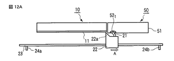
図12A乃至図12Dは、本発明の第2の実施形態の変形例に於ける、インクジェット記録装置のワイピング機構の動作を説明するための図である。   12A to 12D are views for explaining the operation of the wiping mechanism of the ink jet recording apparatus in a modification of the second embodiment of the present invention.

この変形例が前述した第2の実施形態と異なるのは、ブレード支持体に突起を形成して、インク吸収体に吸収されているインクを絞り出す点である。   This modification is different from the second embodiment described above in that protrusions are formed on the blade support and the ink absorbed in the ink absorber is squeezed out.

ブレード支持体22の記録ヘッド10及びインク吸収体51と対向する側で、クリーニング時のブレード支持体22の進行方向に対してブレード部21の後方に、インク放出部材としての突起22aが形成されている。この突起22aが、インク吸収体51を押圧することにより、該インク吸収体51に吸収されているインクが絞り出されるようになっている。尚、この突起22aの高さは、インク吸収体51を押圧可能で、且つノズルプレート11の下面に接触しない高さとする。   On the side of the blade support 22 facing the recording head 10 and the ink absorber 51, a protrusion 22a as an ink discharge member is formed behind the blade portion 21 with respect to the traveling direction of the blade support 22 during cleaning. Yes. When the protrusion 22a presses the ink absorber 51, the ink absorbed by the ink absorber 51 is squeezed out. The height of the protrusion 22a is set to a height at which the ink absorber 51 can be pressed and does not contact the lower surface of the nozzle plate 11.

更に、この変形例のワイピング動作は、前述した図10のフローチャートと同様であるので、詳細な説明は省略する。   Furthermore, the wiping operation of this modification is the same as that of the flowchart of FIG.

図12Aは、ブレード部21が図示矢印A方向に向かって移動し、クリーナ50のインク吸収体51の下面の一端部(左端)に当接した状態を示す模式図である。このように、ブレード部21がインク吸収体31に当接することで、毛細管現象によって、ブレード部21の多孔質の気孔内に抱えられていたインクを、インク吸収体51の多孔質の気孔内へと伝達させることができる。   FIG. 12A is a schematic diagram showing a state in which the blade portion 21 moves in the direction of the arrow A shown in FIG. 12 and contacts one end (left end) of the lower surface of the ink absorber 51 of the cleaner 50. In this way, when the blade portion 21 abuts on the ink absorber 31, the ink held in the porous pores of the blade portion 21 is brought into the porous pores of the ink absorber 51 by capillary action. Can be communicated.

そして、インク吸収体51と当接してブレード支持体22が停止する1回目の位置は、図12Aに示されるように部位521 となり、この位置(部位521 )でブレード部21からインク吸収体51にインクが伝達される。そして、2回目は、1回目よりもブレード支持体22の停止位置が所定時間だけ長くなるので、図12Bに示されるように、部位521 よりも先(右側)の部位522 に、ブレード支持体22が停止する。このとき、この部位522 でブレード部21からインク吸収体51にインクが伝達されると共に、インク吸収体51の前記部位521 に吸収されていたインクが、突起22aによって押圧されて掻き出されて、ブレード支持体22内に流れ込む。図示52は、突起22aによりインク吸収体51から回収されたインクである。 Then, the first position where the blade support 22 stops upon contact with the ink absorber 51 is a part 52 1 as shown in FIG. 12A, and the ink absorber from the blade part 21 at this position (part 52 1 ). Ink is transmitted to 51. The second time, since the stop position of the blade support 22 than the first is longer by a predetermined time, as shown in FIG. 12B, the portion 52 2 of the first (right) than to the region 52 1, blade support The body 22 stops. At this time, ink is transmitted from the blade portion 21 to the ink absorber 51 through the portion 52 2 , and the ink absorbed in the portion 52 1 of the ink absorber 51 is pressed and scraped out by the protrusion 22a. And flows into the blade support 22. 52 shown in the figure is ink recovered from the ink absorber 51 by the protrusion 22a.

同様にして、図12Cに示されるように、3回目は2回目より更に先の位置となる部位523 に、ブレード支持体22が停止して、部位523 でブレード部21からインク吸収体51にインクが伝達される。それと共に、突起22aによって、インク吸収体51の前記部位521 及び522 に吸収されていたインクが掻き出されて、ブレード支持体22内に流れ込む。 Similarly, as shown in FIG. 12C, the third time portion 52 3 which is a farther position than the second, the blade support 22 is stopped, the ink absorbing member 51 from the blade portion 21 at a site 52 3 Ink is transmitted to. At the same time, the ink absorbed in the portions 52 1 and 52 2 of the ink absorber 51 is scraped out by the protrusion 22 a and flows into the blade support 22.

そして、図12Dに示されるように、n回目には、インク吸収体51の他端部(右端)まで行き着いた位置となる部位51n に停止する。このときは、インク吸収体51の部位52n でブレード部21からインク吸収体51にインクが伝達されると共に、突起22aによって、部位521 〜52n-1 に吸収されていたインクが掻き出されて、ブレード支持体22内に流れ込む。 Then, as shown in FIG. 12D, at the n-th time, the ink absorber 51 stops at a part 51 n that reaches the other end (right end). At this time, the ink is transmitted from the blade portion 21 to the ink absorber 51 through the portion 52 n of the ink absorber 51, and the ink absorbed into the portions 52 1 to 52 n-1 is scraped out by the protrusion 22a. And flows into the blade support 22.

この後は、再び図12Aに示される1回目の位置にブレード支持体22が停止するようになり、以降、前述した動作が繰り返される。   Thereafter, the blade support 22 stops again at the first position shown in FIG. 12A, and thereafter, the above-described operation is repeated.

前述した第2の実施形態では、インク吸収体の左側部分が、クリーニングの度に何度もブレードと当接するためインク吸収量が多く飽和しやすくなっていたが、本変形例によれば、クリーニング実施毎にインク吸収体内のインクを掻き出すようにしているので、インクが飽和しないようになっている。   In the second embodiment described above, the left side portion of the ink absorber is in contact with the blade many times each time cleaning is performed, so that the amount of ink absorbed is likely to be saturated, but according to this modification, the cleaning is performed. Since the ink in the ink absorbing body is scraped out every time, the ink is not saturated.

尚、本変形例では、クリーニング時の進行方向に対して、突起をブレード支持体の後方に設けていたが、前方に設けてもよい。   In this modification, the protrusion is provided on the rear side of the blade support with respect to the traveling direction during cleaning, but may be provided on the front side.

(第3の実施形態)
次に、本発明の第3の実施形態について説明する。
(Third embodiment)
Next, a third embodiment of the present invention will be described.

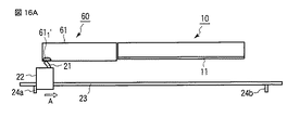
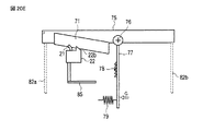
前述した第2の実施形態では、記録ヘッドのワイプ直後にブレード部をクリーナに当接させていたが、この第3の実施形態では、記録ヘッドのワイピングから戻ってきてからブレード部をクリーナに当接させるようにしている。更に、ブレード部の停止位置を、クリーニング毎に延ばしていく(順次左側にずらしていく)ようにしている。   In the second embodiment described above, the blade portion is brought into contact with the cleaner immediately after the recording head is wiped. In this third embodiment, the blade portion is brought into contact with the cleaner after returning from the wiping of the recording head. I try to contact them. Further, the stop position of the blade portion is extended for each cleaning (sequentially shifted to the left).

図13A乃至図13Dは、本発明の第3の実施形態に於けるインクジェット記録装置のワイピング機構の動作を説明するための図である。   13A to 13D are diagrams for explaining the operation of the wiping mechanism of the ink jet recording apparatus according to the third embodiment of the present invention.

本第3の実施形態に於いて、クリーナ60は、記録ヘッド10に隣接し、且つブレード移動方向の延長上に配設されたインク吸収体61を有して構成され、クリーニング時の進行方向に対して、記録ヘッド10の後方に配設されている。また、インク吸収体61のブレード部21と当接する面は、ノズルプレート11の下面よりも僅かに低く配置される。   In the third embodiment, the cleaner 60 includes an ink absorber 61 that is adjacent to the recording head 10 and disposed on the extension of the blade movement direction, and is in the direction of progress during cleaning. On the other hand, it is arranged behind the recording head 10. Further, the surface of the ink absorber 61 that contacts the blade portion 21 is disposed slightly lower than the lower surface of the nozzle plate 11.

次に、このように構成されたワイピング機構によって、記録ヘッド10のノズルブレード11をワイピングする動作について、図13A乃至図13D、図15の動作説明図及び図14のフローチャートを参照して説明する。   Next, the operation of wiping the nozzle blade 11 of the recording head 10 by the wiping mechanism configured as described above will be described with reference to FIGS. 13A to 13D, the operation explanatory diagrams of FIG. 15, and the flowchart of FIG.

尚、図14のフローチャートに於けるステップS52〜S53、S55、S63、S65〜S68、及びステップS72〜S73は、図5のフローチャートのステップS2〜S3、S5、S12、S14〜S17、及びステップS18〜S19と同様の処理を行うので、それぞれ対応するステップ番号を参照して、ここでは説明は省略する。   Note that steps S52 to S53, S55, S63, S65 to S68, and steps S72 to S73 in the flowchart of FIG. 14 are steps S2 to S3, S5, S12, S14 to S17, and step S18 of the flowchart of FIG. Since the same processing as in S19 is performed, the corresponding step number is referred to and the description thereof is omitted here.

ワイピング開始にあたり、ステップS51にて、図15に示されるように、ブレード支持体駆動用モータ44の駆動時間初期値t21、ストッパ24bでのブレード支持体22の停止時間t2、ガイドレール昇降用モータ45の駆動時間t3及びワイピング回数w1が、それぞれ設定される。尚、t21は、クリーナ60にブレード部21が当接しつつ、ワイピングが可能な最小値(MIN)に設定される。   At the start of wiping, in step S51, as shown in FIG. 15, the initial drive time t21 of the blade support driving motor 44, the stop time t2 of the blade support 22 at the stopper 24b, the guide rail lifting motor 45 The driving time t3 and the number of times of wiping w1 are set. Note that t21 is set to a minimum value (MIN) that allows wiping while the blade portion 21 is in contact with the cleaner 60.

次いで、ステップS52にて、タイマカウント値tw、ts、tgがそれぞれリセットされると共に、ワイピング回数カウント値wがリセットされ、続くステップS53にて、ブレード支持体駆動用モータ44がオンされて、タイマカウント(tw)が開始される。これにより、ブレード支持体22が図示矢印A方向に移動開始され、ワイピングが開始される。   Next, in step S52, the timer count values tw, ts, tg are reset, and the wiping count value w is reset. In the subsequent step S53, the blade support driving motor 44 is turned on, and the timer Counting (tw) is started. As a result, the blade support 22 starts to move in the direction indicated by the arrow A, and wiping is started.

図13Aは、ブレード部21が、クリーナ60のインク吸収体61の下面の一端部(右端)のホームポジションで当接した状態を示す模式図である。このように、ブレード部21がインク吸収体61に当接することで、毛細管現象によって、ブレード部21の多孔質の気孔内に抱えられていたインクを、インク吸収体61の多孔質の気孔内へと伝達させることができる。   FIG. 13A is a schematic diagram illustrating a state in which the blade portion 21 is in contact with the home position of one end portion (right end) of the lower surface of the ink absorber 61 of the cleaner 60. In this way, when the blade portion 21 abuts on the ink absorber 61, the ink held in the porous pores of the blade portion 21 is brought into the porous pores of the ink absorber 61 by capillary action. Can be communicated.

また、ワイピングの間、ステップS54に於いて、タイマカウント値twが監視されてブレード支持体駆動用モータ44の駆動時間初期値t21に到達したか否かが判定される。その結果、タイマカウント値twが前記駆動時間初期値t21に到達したならば、ステップS55に移行して、ブレード支持体駆動用モータ44がオフにされて、タイマカウントtwが終了及びリセットされる。   During wiping, in step S54, the timer count value tw is monitored to determine whether or not the driving time initial value t21 of the blade support driving motor 44 has been reached. As a result, if the timer count value tw reaches the drive time initial value t21, the process proceeds to step S55, where the blade support driving motor 44 is turned off, and the timer count tw is ended and reset.

図13Bは、ブレード支持体22がストッパ24bに当接され、図示矢印A方向の移動が停止された状態を示す模式図である。こうして、ブレード支持体22の矢印A方向への移動が停止される。   FIG. 13B is a schematic diagram showing a state in which the blade support 22 is brought into contact with the stopper 24b and the movement in the direction of the arrow A is stopped. Thus, the movement of the blade support 22 in the direction of arrow A is stopped.

次に、ステップS56にて、ガイドレール昇降用モータ45がオンにされ、ガイドレール23が下降される。これにより、図示されないが、ブレード支持体22を支持しているガイドレール23は、記録ヘッド10から遠ざかるように下降される。そして、ステップS57にて、タイマカウント(tg)が開始される。更に、ステップS58に於いて、タイマカウント値tgが監視されてガイドレール昇降用モータ45の駆動時間t3に到達したか否かが判定される。その結果、タイマカウント値tgが前記駆動時間t3に到達したならば、ステップS59に移行して、ガイドレール昇降用モータ45がオフにされ、タイマカウントtgが終了すると共にリセットされる。つまり、ガイドレール23の下降が停止される。   Next, in step S56, the guide rail raising / lowering motor 45 is turned on, and the guide rail 23 is lowered. As a result, although not shown, the guide rail 23 supporting the blade support 22 is lowered so as to move away from the recording head 10. In step S57, the timer count (tg) is started. Further, in step S58, the timer count value tg is monitored to determine whether or not the driving time t3 of the guide rail raising / lowering motor 45 has been reached. As a result, if the timer count value tg reaches the drive time t3, the process proceeds to step S59, where the guide rail elevating motor 45 is turned off, and the timer count tg ends and is reset. That is, the lowering of the guide rail 23 is stopped.

そして、ステップS60にて、駆動時間初期値t21がインクリメント(1秒追加)される。すなわち、t21に1秒が追加されることで、ブレード支持体22の戻し時間(戻し移動量)が増やされる。これにより、2回目のワイピング開始前のブレード支持体22の停止位置は、図13Cに示されるように、1回目の停止位置(611 )の左側(612 )に移動するようになる。 In step S60, the drive time initial value t21 is incremented (added 1 second). That is, by adding 1 second to t21, the return time (return movement amount) of the blade support 22 is increased. Accordingly, the stop position of the blade support 22 before the start of the second wiping is moved to the left side (61 2 ) of the first stop position (61 1 ) as shown in FIG. 13C.

また、インク吸収体61の長さを考慮して、駆動時間初期値t21をインクリメントできる秒数の最大値(MAX値)を考慮しておく。そのため、ステップS61にて、駆動時間初期値t21がMAX値に達するか、若しくは越えるかが監視される。その結果、駆動時間初期値t21がMAX値に達するか、若しくは越えた場合には、ステップS62に移行して、駆動時間初期値t21が初期値(MIN値)に戻される。尚、前記ステップS61にて駆動時間初期値t21がMAX値以下であった場合は、ステップS62がスキップされる。   In consideration of the length of the ink absorber 61, the maximum value (MAX value) of the number of seconds in which the drive time initial value t21 can be incremented is taken into consideration. Therefore, in step S61, it is monitored whether the driving time initial value t21 reaches or exceeds the MAX value. As a result, when the drive time initial value t21 reaches or exceeds the MAX value, the process proceeds to step S62, and the drive time initial value t21 is returned to the initial value (MIN value). If the drive time initial value t21 is less than or equal to the MAX value in step S61, step S62 is skipped.

次に、ステップS63にて、ブレード支持体駆動用モータ44が逆方向に駆動されるべくオンされ、タイマカウントtwが開始される。これにより、ブレード支持体22が、クリーナ60側に向かって移動開始される。そして、続くステップS64に於いて、タイマカウント値twが監視されてブレード支持体駆動用モータ44の駆動時間初期値t21に到達したか否かが判定される。その結果、タイマカウント値twが前記駆動時間初期値t21に到達したならば、ステップS65に移行する。   Next, in step S63, the blade support driving motor 44 is turned on to be driven in the reverse direction, and the timer count tw is started. As a result, the blade support 22 starts to move toward the cleaner 60 side. In subsequent step S64, the timer count value tw is monitored to determine whether or not the driving time initial value t21 of the blade support driving motor 44 has been reached. As a result, if the timer count value tw reaches the drive time initial value t21, the process proceeds to step S65.

ステップS65〜S68では、ガイドレール23が上昇して、図13Cに示されるように、ブレード支持体22がインク吸収体61の2回目の停止位置(612 )に位置づけられる。ここで、ブレード部21をインク吸収体61に当接させた状態で停止させるために、ステップS69にて、その停止時間のカウントtsが開始される。この停止時間t2だけ停止させることで、ブレード部21内に吸収されたインクが、インク吸収体61の所定の部位612 に伝達される。 In steps S65 to S68, the guide rail 23 is raised, and the blade support 22 is positioned at the second stop position (61 2 ) of the ink absorber 61 as shown in FIG. 13C. Here, in order to stop the blade portion 21 in a state where it is in contact with the ink absorber 61, the stop time count ts is started in step S69. By simply stopping the stop time t2, the ink absorbed in the blade portion 21 is transmitted to a predetermined portion 61 2 of the ink absorber 61.

そして、ステップS70に於いて、タイマカウント値tsが監視されてブレード支持体22の停止時間t2に到達したならば、ステップS71に移行して、タイマカウントtsが終了及びリセットされる。   In step S70, when the timer count value ts is monitored and the stop time t2 of the blade support 22 is reached, the process proceeds to step S71, where the timer count ts is ended and reset.

その後、ステップS72にてワイピング回数w1がインクリメントされ、更にステップS73に於いて、所定のワイピング回数wに到達したか否かが判定される。ここで、まだ所定のワイピング回数wに到達していなければ、前記ステップS3に移行して、前述した処理動作が繰り返される。一方、ステップS73にて、所定のワイピング回数wに到達したならば、ステップS74に移行する。   Thereafter, in step S72, the wiping count w1 is incremented, and in step S73, it is determined whether or not the predetermined wiping count w has been reached. If the predetermined wiping count w has not yet been reached, the process proceeds to step S3 and the above-described processing operation is repeated. On the other hand, if the predetermined number of wiping times w is reached in step S73, the process proceeds to step S74.

図13Dは、ブレード部21が、クリーナ60のインク吸収体61の下面の他端部(左端)で当接した状態を示す模式図である。すなわち、所定のワイピング回数wに到達したn回目の停止位置(61n )に、ブレード支持体22が停止された状態である。 FIG. 13D is a schematic diagram illustrating a state in which the blade portion 21 is in contact with the other end portion (left end) of the lower surface of the ink absorber 61 of the cleaner 60. That is, the blade support 22 is stopped at the n-th stop position (61 n ) that has reached the predetermined number of wiping operations w.

そして、ステップS74では、ブレード支持体22が、図13Aのホームポジションに戻されるべく、前記駆動時間初期値t21が初期値に設定される。その後、本シーケンスが終了する。   In step S74, the drive time initial value t21 is set to an initial value so that the blade support 22 is returned to the home position in FIG. 13A. Thereafter, this sequence ends.

このように、第3の実施形態は、ブレード支持体22の停止位置をクリーニング毎に延ばして(順次左側にずらして)いき、クリーナへの最初の当て付け位置は、記録ヘッドに最も近い位置、つまり、クリーナに於ける右端としている。したがって、インク吸収体の記録ヘッド側端部は毎回ブレード部が当接してしまうものの、停止位置が異なることにより、インク吸収能力の高い部位にブレード部を当接させることができる。   As described above, in the third embodiment, the stop position of the blade support 22 is extended for each cleaning (sequentially shifted to the left), and the first contact position on the cleaner is the position closest to the recording head, In other words, the right end of the cleaner. Therefore, although the blade portion comes into contact with the recording head side end portion of the ink absorber every time, the blade portion can be brought into contact with a portion having a high ink absorption capability due to a different stop position.

(第3の実施形態の変形例)
次に、本発明の第3の実施形態の変形例について説明する。
(Modification of the third embodiment)
Next, a modification of the third embodiment of the present invention will be described.

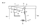
前述した第3の実施形態では、記録ヘッドのワイピングから戻ってきてからブレード部をクリーナに当接させ、且つ、ブレード部の停止位置を、クリーニング毎に延ばしていく(順次左側にずらしていく)ようにしているが、これに限られるものではない。この辺零例では、ブレードの停止位置をクリーニング毎に短縮していく(順次右側にずらしていく)ようにしている。   In the above-described third embodiment, after returning from the wiping of the recording head, the blade portion is brought into contact with the cleaner, and the stop position of the blade portion is extended for each cleaning (sequentially shifted to the left). However, it is not limited to this. In this side zero example, the stop position of the blade is shortened for each cleaning (sequentially shifted to the right).

図16A乃至図16Dは、本発明の第3の実施形態の変形例に於けるワイピング機構の動作を説明するための図である。この図16A乃至図16Dに示されるワイピング機構の構成は、ブレード支持体22の停止位置以外は図13A乃至図13Dに示されるワイピング機構の構成と同じであるので、詳細な説明は省略する。   16A to 16D are views for explaining the operation of the wiping mechanism in a modification of the third embodiment of the present invention. The configuration of the wiping mechanism shown in FIGS. 16A to 16D is the same as the configuration of the wiping mechanism shown in FIGS. 13A to 13D except for the position where the blade support 22 is stopped.

このように構成されたワイピング機構によって、記録ヘッド10のノズルブレード11をワイピングする動作について、図16A乃至図16D、図18の動作説明図及び図17のフローチャートを参照して説明する。   The operation of wiping the nozzle blade 11 of the recording head 10 by the wiping mechanism configured as described above will be described with reference to the operation explanatory diagrams of FIGS. 16A to 16D and FIG. 18 and the flowchart of FIG.

尚、図17のフローチャートに於けるステップS82〜S83、S85〜S89、S93、及びS95〜S103は、図14のフローチャートのステップS52〜S53、S55〜S59、S63及びステップS65〜S73と同様の処理を行うので、それぞれ対応するステップ番号を参照して、ここでは説明は省略する。   Note that steps S82 to S83, S85 to S89, S93, and S95 to S103 in the flowchart of FIG. 17 are the same as steps S52 to S53, S55 to S59, S63, and steps S65 to S73 of the flowchart of FIG. Therefore, the description will be omitted here with reference to the corresponding step numbers.

ワイピング開始にあたり、ステップS81にて、ブレード支持体駆動用モータ44の駆動時間初期値t31、ストッパ24bでのブレード支持体22の停止時間t2、ガイドレール昇降用モータ45の駆動時間t3及びワイピング回数w1が、それぞれ設定される。尚、t31は、クリーナ60にブレード部21が当接しつつ、ワイピングが可能な最大値(MAX)に設定される。   At the start of wiping, in step S81, the initial drive time t31 of the blade support motor 44, the stop time t2 of the blade support 22 at the stopper 24b, the drive time t3 of the guide rail lifting motor 45, and the number of wiping times w1. Are set respectively. Note that t31 is set to a maximum value (MAX) that allows wiping while the blade portion 21 is in contact with the cleaner 60.

次いで、ステップS82にて、タイマカウント値tw、ts、tgがそれぞれリセットされると共に、ワイピング回数カウント値wがリセットされ、続くステップS83にて、ブレード支持体駆動用モータ44がオンされて、タイマカウント(tw)が開始される。これにより、ブレード支持体22が図示矢印A方向に移動開始され、ワイピングが開始される。   Next, in step S82, the timer count values tw, ts, tg are reset, and the wiping count value w is reset. In step S83, the blade support driving motor 44 is turned on, and the timer is reset. Counting (tw) is started. As a result, the blade support 22 starts to move in the direction indicated by the arrow A, and wiping is started.

図16Aは、ブレード部21が、クリーナ60のインク吸収体61の下面の一端部(左端)のホームポジションで当接した状態を示す模式図である。このように、ホームポジション(図18のブレード支持体221 参照)にてブレード部21がインク吸収体61に当接することで、毛細管現象によって、ブレード部21の多孔質の気孔内に抱えられていたインクを、インク吸収体61の多孔質の気孔内へと伝達させることができる。 FIG. 16A is a schematic diagram illustrating a state in which the blade portion 21 is in contact with the home position of one end portion (left end) of the lower surface of the ink absorber 61 of the cleaner 60. In this manner, the blade portion 21 abuts against the ink absorbing member 61 at the home position (see blade support 22 1 in FIG. 18), by capillary action, it has been faced in the pores of the porous of the blade portion 21 Ink can be transferred into the porous pores of the ink absorber 61.

また、ワイピングの間、ステップS84に於いて、タイマカウント値twが監視されてブレード支持体駆動用モータ44の駆動時間初期値t31に到達したか否かが判定される。その結果、タイマカウント値twが前記駆動時間初期値t31に到達したならば、ステップS85に移行して、ブレード支持体駆動用モータ44がオフにされて、タイマカウントtwが終了及びリセットされる。   Further, during wiping, in step S84, the timer count value tw is monitored to determine whether or not the driving time initial value t31 of the blade support driving motor 44 has been reached. As a result, when the timer count value tw reaches the drive time initial value t31, the process proceeds to step S85, the blade support driving motor 44 is turned off, and the timer count tw is ended and reset.

図16Bは、ブレード支持体22がストッパ24bに当接され、図示矢印A方向の移動が停止された状態を示す模式図である。こうして、ブレード支持体22の矢印A方向への移動が停止される(図18のブレード支持体222 参照)。 FIG. 16B is a schematic diagram showing a state in which the blade support 22 is brought into contact with the stopper 24b and the movement in the direction of the arrow A is stopped. Thus, the movement of the blade support 22 in the direction of arrow A is stopped (see the blade support 22 2 in FIG. 18).

次に、ステップS86〜S89に於いて、ガイドレール昇降用モータ45がオンにされ、図18の矢印B方向に、ガイドレール23が下降される。これにより、ブレード支持体22を支持しているガイドレール23は、記録ヘッド10から遠ざかるように下降される(図18のブレード支持体223 参照)。 Next, in steps S86 to S89, the guide rail raising / lowering motor 45 is turned on, and the guide rail 23 is lowered in the direction of arrow B in FIG. Thus, the guide rail 23 which supports the blade support 22, (see blade support 22 3 of FIG. 18) which descends to be away from the recording head 10.

そして、ステップS90にて、駆動時間初期値t31がデクリメント(1秒減少)される。すなわち、t31から1秒を減算することで、ブレード支持体22の戻し時間(戻し移動量)が減らされる。これにより、2回目のワイピング開始前のブレード支持体22の停止位置は、図16Cに示されるように、1回目の停止位置(611 ′)の右側(612 ′)に移動するようになる(図18のブレード支持体224 、225 参照)。 In step S90, the drive time initial value t31 is decremented (decrease by 1 second). That is, by subtracting 1 second from t31, the return time (return movement amount) of the blade support 22 is reduced. Accordingly, the stop position of the blade support 22 before the start of the second wiping is moved to the right side (61 2 ′) of the first stop position (61 1 ′) as shown in FIG. 16C. (See blade support 22 4 , 22 5 in FIG. 18).

また、インク吸収体61の長さを考慮して、駆動時間初期値t31をデクリメントできる秒数の最小値(MIN値)を考慮しておく。そのため、ステップS91にて、駆動時間初期値t31がMIN値に達するか、若しくは小さくなるかが監視される。その結果、駆動時間初期値t31がMIN値に達するか、若しくは小さくなった場合には、ステップS92に移行して、駆動時間初期値t31が初期値(MAX値)に戻される。尚、前記ステップS91にて駆動時間初期値t31がMIN値より小さい場合は、ステップS92がスキップされる。   Further, in consideration of the length of the ink absorber 61, a minimum value (MIN value) of the number of seconds in which the drive time initial value t31 can be decremented is taken into consideration. Therefore, in step S91, it is monitored whether the drive time initial value t31 reaches the MIN value or becomes smaller. As a result, when the drive time initial value t31 reaches the MIN value or becomes smaller, the process proceeds to step S92, and the drive time initial value t31 is returned to the initial value (MAX value). If the drive time initial value t31 is smaller than the MIN value in step S91, step S92 is skipped.

次に、ステップS93にて、ブレード支持体駆動用モータ44が逆方向に駆動されるべくオンされ、タイマカウントtwが開始される。これにより、ブレード支持体22が、図18の矢印C方向に向かって移動開始される。そして、続くステップS94に於いて、タイマカウント値twが監視されてブレード支持体駆動用モータ44の駆動時間初期値t31に到達したか否かが判定される。その結果、タイマカウント値twが前記駆動時間初期値t31に到達したならば、ステップS95に移行する。   Next, in step S93, the blade support driving motor 44 is turned on to be driven in the reverse direction, and the timer count tw is started. As a result, the blade support 22 starts to move in the direction of arrow C in FIG. In subsequent step S94, the timer count value tw is monitored to determine whether or not the driving time initial value t31 of the blade support driving motor 44 has been reached. As a result, if the timer count value tw reaches the drive time initial value t31, the process proceeds to step S95.

ステップS95〜S103では、ブレード支持体22が、図18の矢印C方向及びD方向に移動されて、ブレード支持体22がインク吸収体61の2回目の停止位置(612 ′)に位置づけられる。すなわち、ブレード支持体22は、図18のブレード支持体224 の停止位置からブレード支持体225 の停止位置に、矢印65で表されるようにシフトされる。その後、所定のワイピング回数wに到達したならば、ステップS104に移行する。 In steps S95 to S103, the blade support 22 is moved in the directions indicated by arrows C and D in FIG. 18, and the blade support 22 is positioned at the second stop position (61 2 ′) of the ink absorber 61. That is, the blade support 22 is shifted from the stop position of the blade support 22 4 in FIG. 18 to the stop position of the blade support 22 5 as indicated by the arrow 65. Thereafter, when the predetermined number of wiping times w is reached, the process proceeds to step S104.

図16Dは、ブレード部21が、クリーナ60のインク吸収体61の下面の他端部(右端)で当接した状態を示す模式図である。すなわち、所定のワイピング回数wに到達したn回目の停止位置(61n ′)に、ブレード支持体22が停止された状態である。 FIG. 16D is a schematic diagram illustrating a state in which the blade portion 21 is in contact with the other end portion (right end) of the lower surface of the ink absorber 61 of the cleaner 60. That is, the blade support 22 is stopped at the n-th stop position (61 n ′) that has reached the predetermined wiping count w.

そして、ステップS104では、ブレード支持体22が、図16Aのホームポジションに戻されるべく、前記駆動時間初期値t31が初期値に設定される。その後、本シーケンスが終了する。   In step S104, the drive time initial value t31 is set to an initial value so that the blade support 22 is returned to the home position in FIG. 16A. Thereafter, this sequence ends.

このように、第3の実施形態の変形例は、ブレード支持体22の停止位置をクリーニング毎に短くして(順次右側にずらして)いき、クリーナへの最初の当て付け位置は、記録ヘッドから最も遠い位置、つまり、クリーナに於ける左端としている。したがって、インク吸収体の記録ヘッド側端部は毎回ブレード部が当接してしまうものの、停止位置が異なることにより、インク吸収能力の高い部位にブレード部を当接させることができる。   As described above, in the modified example of the third embodiment, the stop position of the blade support 22 is shortened (sequentially shifted to the right) for each cleaning, and the initial contact position to the cleaner is determined from the recording head. The farthest position, that is, the left edge of the cleaner. Therefore, although the blade portion comes into contact with the recording head side end portion of the ink absorber every time, the blade portion can be brought into contact with a portion having a high ink absorption capability due to a different stop position.

(第4の実施形態)
次に、本発明の第4の実施形態について説明する。
(Fourth embodiment)
Next, a fourth embodiment of the present invention will be described.

本第4の実施形態では、前述した第2の実施形態と同様に、クリーナは、記録ヘッドに隣接し、且つブレード支持体のクリーニング時の進行方向で前方側に配設され、更にクリーナのインク吸収体をブレード支持体によって移動させるようにしている。   In the fourth embodiment, as in the second embodiment described above, the cleaner is disposed adjacent to the recording head and on the front side in the advancing direction during the cleaning of the blade support. The absorber is moved by the blade support.

図19A乃至図19Dは、本発明の第4の実施形態に於けるインクジェット記録装置のワイピング機構の動作を説明するための図である。   19A to 19D are views for explaining the operation of the wiping mechanism of the ink jet recording apparatus according to the fourth embodiment of the present invention.

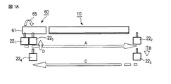
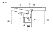
本第4の実施形態に於いて、クリーナ70は、記録ヘッド10に隣接し、且つブレード移動方向の延長上に配設されたインク吸収体71を有して構成される。そして、インク吸収体71は、例えば矩形状であり、少なくともブレード部21と当接する面は、記録ヘッド10に近接する側の部位ではノズルプレート11の下面とほぼ等しく、他方の部位では前記一方の部位よりも低くなるように傾斜が設けられている。更に、このクリーナ70は、前記ノズルプレート11に対して垂直方向に沿って段階的に移動可能となるラッチ機構により、上昇/下降するように構成されている。   In the fourth embodiment, the cleaner 70 includes an ink absorber 71 that is adjacent to the recording head 10 and disposed on an extension in the blade movement direction. The ink absorber 71 has, for example, a rectangular shape, and at least the surface in contact with the blade portion 21 is substantially equal to the lower surface of the nozzle plate 11 at a portion close to the recording head 10, and the one portion at the other portion. An inclination is provided so as to be lower than the portion. Further, the cleaner 70 is configured to be raised / lowered by a latch mechanism that can move stepwise along the vertical direction with respect to the nozzle plate 11.

また、ブレード支持体22の記録ヘッド10及びインク吸収体71と対向する側で、クリーニング時のブレード支持体22の進行方向に対してブレード部21の前方に、突起22bが形成されている。この突起22bは、後述するように、インク吸収体71を押圧すると共に上方に押し上げることにより、該インク吸収体71の高さが変化するようになっている。尚、この突起22bの高さは、インク吸収体71を押し上げ可能で、且つノズルプレート11の下面に接触しない高さとする。   Further, on the side of the blade support 22 facing the recording head 10 and the ink absorber 71, a protrusion 22b is formed in front of the blade portion 21 with respect to the traveling direction of the blade support 22 during cleaning. As will be described later, the protrusion 22b presses the ink absorber 71 and pushes it upward to change the height of the ink absorber 71. Note that the height of the protrusion 22b is set so that the ink absorber 71 can be pushed up and does not contact the lower surface of the nozzle plate 11.

図20A乃至図20Jは、前記ラッチ機構の構成及び動作を説明するための図である。   20A to 20J are views for explaining the configuration and operation of the latch mechanism.

このラッチ機構100は、クリーナ70のインク吸収体71を上昇/下降させるための指示手段である吸収体支持部材75と、ラッチ解除時に回転する回転軸76と、この回転軸76を中心に回動するラッチ部材77と、このラッチ部材77に取り付けられたストッパ部材78と、前記ラッチ部材77をストッパ部材78に押しつけるためのばね等の付勢部材79と、ラッチ部材77が横方向へ逃げる場合の移動ガイドとなる回転スライド支持体81と、吸収体支持部材75の上下方向への移動ガイドとなる上下スライド支持体82a及び82bと、ブレード支持体22に取付けられた押し当て部材85と、を有して構成される。   The latch mechanism 100 is an absorber support member 75 that is an instruction means for raising / lowering the ink absorber 71 of the cleaner 70, a rotation shaft 76 that rotates when the latch is released, and a rotation about the rotation shaft 76. A latch member 77, a stopper member 78 attached to the latch member 77, a biasing member 79 such as a spring for pressing the latch member 77 against the stopper member 78, and a case where the latch member 77 escapes in the lateral direction. Rotating slide support 81 serving as a movement guide, upper and lower slide supports 82a and 82b serving as movement guides in the vertical direction of the absorber support member 75, and a pressing member 85 attached to the blade support 22. Configured.

次に、このように構成されたワイピング機構によって、記録ヘッド10のノズルブレード11をワイピングする動作について、図19A乃至図19Dと、図20A乃至図20Jを参照して説明する。   Next, an operation of wiping the nozzle blade 11 of the recording head 10 by the wiping mechanism configured as described above will be described with reference to FIGS. 19A to 19D and FIGS. 20A to 20J.

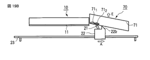
図19Aは、ノズルプレートのワイピングが終了して、ブレード支持体22に設けられた突起22bがクリーナ30に当接し、インク吸収体71の一端部(左端)に、ブレード支持体22が停止された状態を示した図である。   In FIG. 19A, the wiping of the nozzle plate is finished, the protrusion 22b provided on the blade support 22 abuts against the cleaner 30, and the blade support 22 is stopped at one end (left end) of the ink absorber 71. It is the figure which showed the state.

この場合、1回目の停止位置(部位711 )にて、インク吸収体71はブレード支持体22のブレード部21と密着している間、該ブレード部21に付着または吸収されているインクを吸収する。このとき、突起22bがインク吸収体71を押圧することにより、インク吸収体71に吸収されているインクが絞り出される。それと同時に、インク吸収体71に突起22bが押し付けられることによって、インク吸収体71が上方へ移動する。 In this case, at the first stop position (part 71 1 ), while the ink absorber 71 is in close contact with the blade portion 21 of the blade support 22, the ink adhering to or absorbed by the blade portion 21 is absorbed. To do. At this time, the protrusion 22b presses the ink absorber 71, whereby the ink absorbed by the ink absorber 71 is squeezed out. At the same time, the protrusion 22b is pressed against the ink absorber 71, whereby the ink absorber 71 moves upward.

すなわち、図20Aに示されるように、記録ヘッド10のワイプが終了し、インク吸収体71にブレード部21が突き当たる。インク吸収体71は吸収体支持部材75に取付けられており、該吸収体支持部材75は上下方向に可動となっている。吸収体支持部材75は、ラッチ部材77がストッパ部材78に載っていることで、吸収体支持部材75の自重とラッチによって位置が固定されている。   That is, as shown in FIG. 20A, the wiping of the recording head 10 is completed, and the blade portion 21 hits the ink absorber 71. The ink absorber 71 is attached to an absorber support member 75, and the absorber support member 75 is movable in the vertical direction. The position of the absorber support member 75 is fixed by the weight of the absorber support member 75 and the latch, because the latch member 77 is placed on the stopper member 78.

そして、図20Bに示されるように、ブレード支持体22のブレード部21がインク吸収体71に当たる力で、インク吸収体71の吸収体支持部材75が上方(図示矢印E方向)に持ち上がる。このとき、ラッチ部材77が回転軸76を中心に図示矢印F方向に回転することで、ストッパ部材78がラッチを乗り越える。すると、ストッパ部材78が相対的にラッチ部材77の下方向に移動する。   20B, the absorber support member 75 of the ink absorber 71 is lifted upward (in the direction of arrow E in the figure) by the force with which the blade portion 21 of the blade support 22 hits the ink absorber 71. At this time, the latch member 77 rotates around the rotation shaft 76 in the direction of the arrow F, so that the stopper member 78 gets over the latch. Then, the stopper member 78 moves relatively downward in the latch member 77.

次に、図20Cに示されるように、ストッパ部材78がラッチを乗り越え終わると、ラッチ部材77が図示矢印G方向に回転して再びラッチにかかる。すると、吸収体支持部材75が上方向に移動して、その位置に固定される。   Next, as shown in FIG. 20C, when the stopper member 78 finishes over the latch, the latch member 77 rotates in the direction of the arrow G in the drawing and is latched again. Then, the absorber support member 75 moves upward and is fixed at that position.

その後、図20Dに示されるように、ブレード支持体22が図示矢印H方向に下降する。また、ここでは図示されないが、ブレード支持体22は、再びワイプ開始位置(ホームポジション)に復帰して、次回のワイプに備える。そして、図1や図4Aと同様なホームポジションから、ブレード支持体22が、ブレード支持体駆動用モータ44の駆動によりガイドレール23に沿って移動する。   Thereafter, as shown in FIG. 20D, the blade support 22 descends in the direction of the arrow H shown. Although not shown here, the blade support 22 returns to the wipe start position (home position) again and prepares for the next wipe. Then, from the same home position as in FIG. 1 or FIG. 4A, the blade support 22 moves along the guide rail 23 by driving the blade support driving motor 44.

こうして、再びブレード部21によるワイプ動作が行われると、図20Eに示されるように、インク吸収体71にブレード支持体22が突き当たる。このとき、インク吸収体71の位置が前回(1回目)よりも高くなっているため、ワイプ動作距離を長くすることでインク吸収体71に突き当たる。すなわち、2回目は、1回目とは異なる位置、この場合右側にブレード支持体22を停止させる。この2回目の停止位置は、図19Bに示されるように、ブレード部21が、1回目の突起22bの停止位置近傍となる。そして、ブレード部21が、1回目の部位711 の右側の部位712 に当接することにより、ブレード部21の多孔質の気孔内に抱えられていたインクを、インク吸収体71の多孔質の気孔内へと伝達させることができる。 Thus, when the wiping operation by the blade portion 21 is performed again, the blade support 22 abuts against the ink absorber 71 as shown in FIG. 20E. At this time, since the position of the ink absorber 71 is higher than the previous time (first time), the ink absorber 71 hits the ink absorber 71 by increasing the wipe operation distance. That is, the blade support 22 is stopped on the right side in the second time, a position different from the first time. As shown in FIG. 19B, the second stop position is near the stop position of the first protrusion 22b. Then, when the blade portion 21 abuts on the right portion 71 2 of the first portion 71 1 , the ink held in the porous pores of the blade portion 21 is removed from the porous portion of the ink absorber 71. It can be transmitted into the pores.

このとき、図20Fに示されるように、再び、ブレード支持体22がインク吸収体71に当たる力で、インク吸収体71の吸収体支持部材75が上方(図示矢印E方向)に持ち上がる。そして、ラッチ部材77が回転軸76を中心に回動することで、ストッパ部材78がラッチを乗り越える。そして、ストッパ部材78が相対的にラッチ部材77の下方向に移動する。   At this time, as shown in FIG. 20F, the absorber support member 75 of the ink absorber 71 is lifted upward (in the direction of arrow E in the drawing) by the force with which the blade support 22 strikes the ink absorber 71 again. Then, the latch member 77 rotates around the rotation shaft 76, so that the stopper member 78 gets over the latch. Then, the stopper member 78 moves relatively downward in the latch member 77.

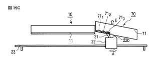
その後、ワイプ毎に前述したラッチの動作が繰り返され、ワイプ毎にブレード支持体22のインク吸収体71への突き当たり位置が移動していく。例えば、図19Cに示されるように、3回目は2回目より更に先の位置(右側)となる部位713 に、ブレード支持体22が停止する。 Thereafter, the above-described latch operation is repeated for each wipe, and the abutting position of the blade support 22 against the ink absorber 71 is moved for each wipe. For example, as shown in FIG. 19C, 3 round the site 71 3 serving as a farther position than the second (right), the blade support 22 is stopped.

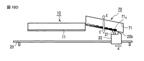
そして、図19Dに示されるように、n回目で、インク吸収体71の他端部(右端)まで行き着いた位置となる部位71n にブレード支持体22が停止すると、図20Gに示されるように、ラッチも使い切って、それ以上には上に上がらない状態となる。このように、ラッチを使い切った位置までブレード支持体22が到達すると、ブレード支持体22に取り付けられている押し当て部材85が、ラッチ部材77に突き当たる。この押し当て部材85がラッチ部材77を押すことにより、図20Hに示されるように、ラッチ部材77が回転軸76を中心に図示矢印F方向に回転して、ラッチが解除される。 Then, as shown in FIG. 19D, when the blade support 22 stops at the portion 71 n that reaches the other end (right end) of the ink absorber 71 at the n-th time, as shown in FIG. 20G. The latch is also used up, and no more can be lifted. As described above, when the blade support 22 reaches the position where the latch is used up, the pressing member 85 attached to the blade support 22 abuts against the latch member 77. When the pressing member 85 pushes the latch member 77, as shown in FIG. 20H, the latch member 77 rotates about the rotation shaft 76 in the direction of the arrow F in the figure, and the latch is released.

ここでラッチが解除されると、ブレード支持体22が下降する。このとき、ラッチが外れているので、図20Iに示されるように、吸収体支持部材75全体が下降する。そして、図20Jに示されるように、更にブレード支持体22が下降すると、押し当て部材85がラッチ部材77から外れる。これにより、ラッチとストッパ部材78が再び係合する。   When the latch is released here, the blade support 22 is lowered. At this time, since the latch is released, the entire absorber support member 75 is lowered as shown in FIG. 20I. Then, as shown in FIG. 20J, when the blade support 22 is further lowered, the pressing member 85 is detached from the latch member 77. Thereby, the latch and the stopper member 78 are engaged again.

そして、ブレード支持体駆動用モータ44及びガイドレール昇降用モータ45が駆動されることによって、ブレード支持体22はホームポジションに戻る。その後、再びワイピングが開始されると、図19A及び図20Aに示されるように、ブレード支持体22は1回目の停止位置にてインク吸収体71を押し上げ、以降、前述した動作が繰り返される。   The blade support 22 is returned to the home position by driving the blade support drive motor 44 and the guide rail lifting / lowering motor 45. Thereafter, when wiping is started again, as shown in FIGS. 19A and 20A, the blade support 22 pushes up the ink absorber 71 at the first stop position, and the above-described operation is repeated thereafter.

このように、第4の実施形態によれば、ブレード支持体22に突起22bを形成してインク吸収体71を押し付けることによって、該インク吸収体71が上方へ移動するので、ブレード部21の当接面は毎回新たな場所となり、また前回当接した場所には当たらないようになっている。したがって、ブレード部21のクリーニング動作を実施する際に、ブレードは常にインク吸収体71の異なる部位(インク吸収能力が高い部位)に対して当接するので、良好なクリーニング特性を長期間に亘って維持することが可能となる。   Thus, according to the fourth embodiment, the protrusion 22b is formed on the blade support 22 and the ink absorber 71 is pressed to move the ink absorber 71 upward. The contact surface becomes a new place every time, and does not hit the place where it contacted last time. Therefore, when performing the cleaning operation of the blade portion 21, the blade always abuts against different parts of the ink absorber 71 (parts having high ink absorption capability), so that good cleaning characteristics are maintained for a long period of time. It becomes possible to do.

(第5の実施形態)
次に、本発明の第5の実施形態について説明する。
(Fifth embodiment)
Next, a fifth embodiment of the present invention will be described.

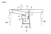
本第5の実施形態では、前述した第4の実施形態と反対に、クリーナは、記録ヘッドに隣接し、且つブレード支持体のクリーニング時の進行方向で後方側に配設され、更にクリーナのインク吸収体をブレード支持体によって移動させるようにしている。   In the fifth embodiment, contrary to the above-described fourth embodiment, the cleaner is disposed adjacent to the recording head and on the rear side in the traveling direction during cleaning of the blade support, and further the ink of the cleaner. The absorber is moved by the blade support.

図21A乃至図21Dは、本発明の第5の実施形態に於けるインクジェット記録装置のワイピング機構の動作を説明するための図である。   21A to 21D are diagrams for explaining the operation of the wiping mechanism of the ink jet recording apparatus according to the fifth embodiment of the present invention.

本第5の実施形態に於いて、クリーナ90は、記録ヘッド10に隣接し、且つブレード移動方向の延長上に配設されたインク吸収体91を有して構成される。そして、インク吸収体91は、例えば矩形状であり、少なくともブレード部21と当接する面は、記録ヘッド10に近接する側の部位ではノズルプレート11の下面とほぼ等しく、他方の部位では前記一方の部位よりも低くなるように傾斜が設けられている。更に、このクリーナ90は、前記ノズルプレート11に対して垂直方向に沿って段階的に移動可能となるラッチ機構により、上昇/下降するように構成されている。但し、このラッチ機構の構成及び動作については、前述した第4の実施形態と同様であるので、ここでは図示及び説明は省略する。   In the fifth embodiment, the cleaner 90 includes an ink absorber 91 that is adjacent to the recording head 10 and disposed on an extension in the blade movement direction. The ink absorber 91 has, for example, a rectangular shape, and at least the surface in contact with the blade portion 21 is substantially equal to the lower surface of the nozzle plate 11 at a portion close to the recording head 10, and the one portion at the other portion. An inclination is provided so as to be lower than the portion. Further, the cleaner 90 is configured to be raised / lowered by a latch mechanism that can move stepwise along the vertical direction with respect to the nozzle plate 11. However, the configuration and operation of the latch mechanism are the same as those in the fourth embodiment described above, and therefore illustration and description thereof are omitted here.

また、ブレード支持体22の記録ヘッド10及びインク吸収体91と対向する側で、クリーニング時のブレード支持体22の進行方向に対してブレード部21の後方に、突起22aが形成されている。この突起22aは、後述するように、インク吸収体91を押圧すると共に上方に押し上げることにより、該インク吸収体91の高さが変化するようになっている。尚、この突起22aの高さは、インク吸収体91を押し上げ可能で、且つノズルプレート11の下面に接触しない高さとする。   Further, on the side of the blade support 22 facing the recording head 10 and the ink absorber 91, a protrusion 22a is formed behind the blade portion 21 with respect to the traveling direction of the blade support 22 during cleaning. As will be described later, the protrusion 22a presses the ink absorber 91 and pushes it upward to change the height of the ink absorber 91. Note that the height of the protrusion 22a is a height that can push up the ink absorber 91 and does not contact the lower surface of the nozzle plate 11.

次に、このように構成されたワイピング機構の動作を説明する。   Next, the operation of the wiping mechanism configured as described above will be described.

図21Aは、ノズルプレートのワイピングが終了後(1回目)で、ブレード支持体22に設けられた突起22aがクリーナ90に当接し、インク吸収体91の一端部(右側)に、ブレード支持体22が停止された状態を示した図である。   In FIG. 21A, after the wiping of the nozzle plate is completed (first time), the protrusion 22a provided on the blade support 22 abuts the cleaner 90, and the blade support 22 is attached to one end (right side) of the ink absorber 91. It is the figure which showed the state by which was stopped.

この場合、1回目の停止位置(部位911 )にて、インク吸収体91はブレード支持体22のブレード部21と密着している間、該ブレード部21に付着または吸収されているインクを吸収する。このとき、インク吸収体91に突起22aが押し付けられることにより、図示されないラッチ機構によって、インク吸収体91が上方(図示矢印E方向)へ移動する。また、同時に、突起22aがインク吸収体91を押圧することにより、前回のクリーニング時にインク吸収体91に吸収されているインクが絞り出される。 In this case, at the first stop position (part 91 1 ), while the ink absorber 91 is in close contact with the blade portion 21 of the blade support 22, the ink adhering to or absorbed by the blade portion 21 is absorbed. To do. At this time, when the protrusion 22a is pressed against the ink absorber 91, the ink absorber 91 moves upward (in the direction of arrow E in the figure) by a latch mechanism (not shown). At the same time, the protrusion 22a presses the ink absorber 91, so that the ink absorbed by the ink absorber 91 during the previous cleaning is squeezed out.

その後、ブレード支持体駆動用モータ44の駆動により、ブレード支持体22がガイドレール23に沿って移動して、ノズルプレート11面上のワイピングが実行される。更に、ガイドレール昇降用モータ45及びブレード支持体駆動用モータ44が駆動されることによって、ブレード支持体22は、図21Bに示されるように、2回目の停止位置に位置づけられる。   Thereafter, the blade support 22 is moved along the guide rail 23 by the drive of the blade support drive motor 44, and wiping on the surface of the nozzle plate 11 is executed. Further, by driving the guide rail raising / lowering motor 45 and the blade support driving motor 44, the blade support 22 is positioned at the second stop position as shown in FIG. 21B.

この2回目の停止位置(部位912 )は、図21Aに示される1回目の停止位置(部位911 )とは異なる位置、この場合左側である。この2回目の停止位置は、図21Bに示されるように、ブレード部21が、1回目の突起22aの停止位置近傍となる。そして、ブレード部21が、1回目の部位911 の左側の部位912 に当接することにより、ブレード部21の多孔質の気孔内に抱えられていたインクを、インク吸収体91の多孔質の気孔内へと伝達させることができる。また、このとき、ブレード支持体22がインク吸収体91に当たる力、及び図示されないラッチ機構によって、インク吸収体91が上方へ僅かに移動する。 The second stop position (part 91 2 ) is a position different from the first stop position (part 91 1 ) shown in FIG. 21A, in this case, the left side. As shown in FIG. 21B, the second stop position is near the stop position of the first protrusion 22a. Then, when the blade portion 21 abuts on the left portion 91 2 of the first portion 91 1 , the ink held in the porous pores of the blade portion 21 is removed from the porous portion of the ink absorber 91. It can be transmitted into the pores. At this time, the ink absorber 91 slightly moves upward by the force of the blade support 22 hitting the ink absorber 91 and a latch mechanism (not shown).

その後、前述と同様にして、ブレード支持体駆動用モータ44の駆動により、ノズルプレート11面上のワイピングが実行される。更に、ガイドレール昇降用モータ45及びブレード支持体駆動用モータ44が駆動されることによって、ブレード支持体22は、図21Cに示されるように、3回目の停止位置(部位913 )に位置づけられる。 Thereafter, in the same manner as described above, wiping on the surface of the nozzle plate 11 is executed by driving the blade support driving motor 44. Further, by driving the guide rail raising / lowering motor 45 and the blade support driving motor 44, the blade support 22 is positioned at the third stop position (part 91 3 ) as shown in FIG. 21C. .

そして、図21Dに示されるように、n回目で、インク吸収体91の他端部(左側)まで行き着いた位置となる部位91n にブレード支持体22が停止すると、インク吸収体91は、それ以上には上に上がらない状態となる。すると、ノズルプレート11面上のワイピングの実行によってブレード支持体22が図示矢印A方向に移動した後、図示されないラッチ機構によってラッチが解除されて、インク吸収体が下降(図示矢印E′方向)し、元の位置に復帰する。 Then, as shown in FIG. 21D, when the blade support 22 stops at the portion 91 n that reaches the other end (left side) of the ink absorber 91 at the n-th time, the ink absorber 91 It will be in the state which does not rise above. Then, after the blade support 22 is moved in the direction of the arrow A by executing wiping on the surface of the nozzle plate 11, the latch is released by a latch mechanism (not shown), and the ink absorber is lowered (in the direction of arrow E '). Return to the original position.

その後、ブレード支持体駆動用モータ44及びガイドレール昇降用モータ45の駆動により、ブレード支持体22は、図21Aに示されるホームポジションに戻る。以降、前述した動作が繰り返される。   Thereafter, the blade support 22 is returned to the home position shown in FIG. 21A by driving the blade support drive motor 44 and the guide rail lifting / lowering motor 45. Thereafter, the above-described operation is repeated.

このように、第5の実施形態によれば、ブレード支持体22に突起22aを形成してインク吸収体91を押し付けることによって、該インク吸収体91が上方へ移動するので、ブレード支持体22の戻り位置はワイプ毎に少しずつ異なる位置となり、またブレード部21の当接面は毎回新たな場所となり、前回当接した場所には当たらないようになっている。したがって、ブレード部21のクリーニング動作を実施する際に、ブレードは常にインク吸収体91の異なる部位(インク吸収能力が高い部位)に対して当接するので、良好なクリーニング特性を長期間に亘って維持することが可能となる。   Thus, according to the fifth embodiment, by forming the protrusion 22a on the blade support 22 and pressing the ink absorber 91, the ink absorber 91 moves upward. The return position is slightly different for each wipe, and the contact surface of the blade portion 21 becomes a new place every time, so that it does not hit the place where it contacted last time. Accordingly, when performing the cleaning operation of the blade portion 21, the blade always abuts against different parts (parts having a high ink absorption capacity) of the ink absorber 91, so that good cleaning characteristics are maintained over a long period of time. It becomes possible to do.

以上、本発明の実施形態について説明したが、本発明は前述した実施形態に限定されるものではなく、本発明の要旨を逸脱しない範囲で種々の変形実施が可能であるのは勿論である。   While the embodiments of the present invention have been described above, the present invention is not limited to the above-described embodiments, and various modifications can be made without departing from the scope of the present invention.

更に、前述した実施形態には種々の段階の発明が含まれており、開示される複数の構成要件の適当な組合せにより種々の発明が抽出され得る。例えば、実施形態に示される全構成要件から幾つかの構成要件が削除されても、発明が解決しようとする課題の欄で述べた課題が解決でき、発明の効果の欄で述べられている効果が得られる場合には、この構成要件が削除された構成も発明として抽出され得る。   Further, the above-described embodiments include inventions at various stages, and various inventions can be extracted by appropriately combining a plurality of disclosed constituent elements. For example, even if some constituent requirements are deleted from all the constituent requirements shown in the embodiment, the problem described in the column of the problem to be solved by the invention can be solved, and the effect described in the column of the effect of the invention Can be obtained as an invention.

本発明の第1の実施形態に係るインクジェット記録装置1に於ける記録ヘッド10及びワイピング機構20、クリーナ30の概略構成を側面から観た模式図である。2 is a schematic view of the schematic configuration of the recording head 10, the wiping mechanism 20, and the cleaner 30 in the inkjet recording apparatus 1 according to the first embodiment of the present invention as viewed from the side. FIG. 図1のクリーナ30の斜視図である。It is a perspective view of the cleaner 30 of FIG. 図1のインクジェット記録装置に於いてワイパブレードのクリーニングに関する制御系のみ示したブロック構成図である。FIG. 2 is a block diagram illustrating only a control system related to cleaning of a wiper blade in the ink jet recording apparatus of FIG. 1. 本発明の第1の実施形態に係るインクジェット記録装置のワイピング動作を説明するためのもので、ワイピングを開始しようとしている直前の状態を示した模式図である。FIG. 6 is a schematic diagram illustrating a state immediately before starting wiping, for explaining a wiping operation of the ink jet recording apparatus according to the first embodiment of the present invention. 本発明の第1の実施形態に係るインクジェット記録装置のワイピング動作を説明するためのもので、ワイピング途中のワイピング機構20と記録ヘッド10の状態を模式化した図である。FIG. 2 is a diagram schematically illustrating a state of the wiping mechanism 20 and the recording head 10 during wiping for explaining the wiping operation of the ink jet recording apparatus according to the first embodiment of the present invention. 本発明の第1の実施形態に係るインクジェット記録装置のワイピング動作を説明するためのもので、ノズルプレート11面上のワイピングが終了し、ブレード部21が記録ヘッド10とクリーナ30との間に位置づけられている状態を示した模式図である。FIG. 2 is a diagram for explaining a wiping operation of the ink jet recording apparatus according to the first embodiment of the present invention, in which wiping on the surface of the nozzle plate 11 is completed, and the blade portion 21 is positioned between the recording head 10 and the cleaner 30. It is the schematic diagram which showed the state currently carried out. 本発明の第1の実施形態に係るインクジェット記録装置のワイピング動作を説明するためのもので、ブレード部21がクリーナ30のインク吸収体31に当接し、ブレード部21が湾曲して、更に図示矢印A方向に向かって移動しようとしている状態を示す模式図である。FIG. 3 is a diagram for explaining the wiping operation of the ink jet recording apparatus according to the first embodiment of the present invention, in which the blade portion 21 comes into contact with the ink absorber 31 of the cleaner 30, the blade portion 21 is curved, and the illustrated arrow It is a schematic diagram which shows the state which is going to move toward A direction. 本発明の第1の実施形態に係るインクジェット記録装置のワイピング動作を説明するためのもので、ブレード支持体22がストッパ24bに当接され、図示矢印A方向の移動が停止された状態を示す模式図である。FIG. 2 is a diagram for explaining a wiping operation of the ink jet recording apparatus according to the first embodiment of the present invention, and is a schematic diagram showing a state in which the blade support 22 is brought into contact with the stopper 24b and the movement in the direction of the arrow A is stopped. FIG. 本発明の第1の実施形態に係るインクジェット記録装置のワイピング動作を説明するためのもので、ブレード支持体22を支持しているガイドレール23を、記録ヘッド10から遠ざかるように、図示矢印B方向に移動させ、ブレード部21をインク吸収体31から離間させた状態を示す模式図である。FIG. 2 is a diagram for explaining a wiping operation of the ink jet recording apparatus according to the first embodiment of the present invention, and illustrates a guide rail 23 supporting a blade support body 22 in the direction indicated by an arrow B so as to move away from the recording head 10. FIG. 6 is a schematic diagram illustrating a state in which the blade portion 21 is moved away from the ink absorber 31. 本発明の第1の実施形態に係るインクジェット記録装置のワイピング動作を説明するためのもので、ブレード支持体22をガイドレール23上のホームポジションに戻すべく、図示矢印C方向に向けて移動させている状態を示す模式図である。FIG. 2 is a diagram for explaining a wiping operation of the ink jet recording apparatus according to the first embodiment of the present invention, in which the blade support 22 is moved in the direction indicated by an arrow C in order to return to the home position on the guide rail 23. It is a schematic diagram which shows the state which exists. 本発明の第1の実施形態に係るインクジェット記録装置のワイピング動作を説明するためのもので、2回目のワイピング動作後にブレード部21がクリーナ30のインク吸収体31に当接し、ブレード部21が湾曲して、更に図示矢印A方向に向かって移動しようとしている状態を示す模式図である。FIG. 3 is a diagram for explaining a wiping operation of the ink jet recording apparatus according to the first embodiment of the present invention, and after the second wiping operation, the blade portion 21 comes into contact with the ink absorber 31 of the cleaner 30 and the blade portion 21 is curved. And it is a schematic diagram which shows the state which is going to move further toward the illustration arrow A direction. 本発明の第1の実施形態に係るインクジェット記録装置のワイピング動作を説明するためのフローチャートである。3 is a flowchart for explaining a wiping operation of the ink jet recording apparatus according to the first embodiment of the present invention. 本発明の第1の実施形態に係るインクジェット記録装置のワイピング動作を説明するための図である。FIG. 5 is a diagram for explaining a wiping operation of the ink jet recording apparatus according to the first embodiment of the present invention. 本発明の第1の実施形態に係るインクジェット記録装置のワイピング動作を説明するためのもので、インク吸収体31に於けるインクを吸収した部位311 、312 と、ブレード部21と当接した範囲351 、352 の例を示した図である。FIG. 2 is a diagram for explaining a wiping operation of the ink jet recording apparatus according to the first embodiment of the present invention, and a portion 31 1 , 31 2 that absorbs ink in an ink absorber 31 and a blade portion 21 are in contact with each other. It is the figure which showed the example of the ranges 35 1 and 35 2 . 本発明の第1の実施形態の変形例に於ける、ワイピング機構の動作を説明するためのもので、ワイピングを開始しようとしている直前の状態を示した模式図である。FIG. 9 is a schematic diagram illustrating a state immediately before starting wiping, for explaining the operation of the wiping mechanism in a modification of the first embodiment of the present invention. 本発明の第1の実施形態の変形例に於ける、ワイピング機構の動作を説明するためのもので、ワイピング途中のワイピング機構20と記録ヘッド10の状態を示した模式図である。FIG. 5 is a schematic diagram illustrating the state of the wiping mechanism 20 and the recording head 10 during wiping, for explaining the operation of the wiping mechanism in a modification of the first embodiment of the present invention. 本発明の第1の実施形態の変形例に於ける、ワイピング機構の動作を説明するためのもので、ノズルプレートのワイピングが終了して、クリーナ30に当接する直前のブレード支持体22の状態を示した模式図である。FIG. 5 is a diagram for explaining the operation of the wiping mechanism in the modification of the first embodiment of the present invention. The state of the blade support 22 immediately before contacting the cleaner 30 after the wiping of the nozzle plate is completed. It is the shown schematic diagram. 本発明の第1の実施形態の変形例に於ける、ワイピング機構の動作を説明するためのもので、ブレード支持体22がクリーナ30に当接し、更に、ブレード支持体22がA方向に向かって移動中であることを示した模式図である。In order to explain the operation of the wiping mechanism in the modified example of the first embodiment of the present invention, the blade support 22 abuts on the cleaner 30 and the blade support 22 moves in the A direction. It is the schematic diagram which showed that it is moving. 本発明の第2の実施形態に於けるインクジェット記録装置のワイピング機構の動作を説明するためのもので、ブレード部21が図示矢印A方向に向かって移動し、1回目の停止位置である、クリーナ50のインク吸収体51の下面の一端部(左端)に当接した状態を示す模式図である。FIG. 7 is a diagram for explaining the operation of the wiping mechanism of the ink jet recording apparatus according to the second embodiment of the present invention, in which the blade portion 21 moves in the direction of the arrow A in FIG. It is a schematic diagram which shows the state contact | abutted at the one end part (left end) of the lower surface of 50 ink absorbers 51. FIG. 本発明の第2の実施形態に於けるインクジェット記録装置のワイピング機構の動作を説明するためのもので、ブレード部21が図示矢印A方向に向かって移動し、2回目の停止位置である、クリーナ50のインク吸収体51の下面に当接した状態を示す模式図である。FIG. 9 is a diagram for explaining the operation of the wiping mechanism of the ink jet recording apparatus according to the second embodiment of the present invention, in which the blade portion 21 moves in the direction of the arrow A in the drawing and is a second stop position. It is a schematic diagram which shows the state contact | abutted to the lower surface of 50 ink absorbers 51. FIG. 本発明の第2の実施形態に於けるインクジェット記録装置のワイピング機構の動作を説明するためのもので、ブレード部21が図示矢印A方向に向かって移動し、3回目の停止位置である、クリーナ50のインク吸収体51の下面に当接した状態を示す模式図である。FIG. 7 is a diagram for explaining the operation of the wiping mechanism of the ink jet recording apparatus according to the second embodiment of the present invention, in which the blade portion 21 moves in the direction of the arrow A shown in FIG. It is a schematic diagram which shows the state contact | abutted to the lower surface of 50 ink absorbers 51. FIG. 本発明の第2の実施形態に於けるインクジェット記録装置のワイピング機構の動作を説明するためのもので、ブレード部21が図示矢印A方向に向かって移動し、n回目の停止位置である、クリーナ50のインク吸収体51の下面に当接した状態を示す模式図である。FIG. 9 is a diagram for explaining the operation of the wiping mechanism of the ink jet recording apparatus according to the second embodiment of the present invention, in which the blade portion 21 moves in the direction of the arrow A in FIG. It is a schematic diagram which shows the state contact | abutted to the lower surface of 50 ink absorbers 51. FIG. 本発明の第2の実施形態に係るインクジェット記録装置のワイピング動作を説明するためのフローチャートである。6 is a flowchart for explaining a wiping operation of an ink jet recording apparatus according to a second embodiment of the present invention. 本発明の第2の実施形態に係るインクジェット記録装置のワイピングの動作を説明するための図である。It is a figure for demonstrating the operation | movement of wiping of the inkjet recording device which concerns on the 2nd Embodiment of this invention. 本発明の第2の実施形態の変形例に於ける、インクジェット記録装置のワイピング機構の動作を説明するためのもので、ブレード部21が図示矢印A方向に向かって移動し、1回目の停止位置である、クリーナ50のインク吸収体51の下面の一端部(左端)に当接した状態を示す模式図である。FIG. 9 is a view for explaining the operation of the wiping mechanism of the ink jet recording apparatus in a modification of the second embodiment of the present invention, in which the blade portion 21 moves in the direction of the arrow A in the drawing, and the first stop position It is a schematic diagram which shows the state which contact | abutted to the one end part (left end) of the lower surface of the ink absorber 51 of the cleaner 50 which is. 本発明の第2の実施形態の変形例に於ける、インクジェット記録装置のワイピング機構の動作を説明するためのもので、ブレード部21が図示矢印A方向に向かって移動し、2回目の停止位置である、クリーナ50のインク吸収体51の下面に当接した状態を示す模式図である。FIG. 9 is a view for explaining the operation of the wiping mechanism of the ink jet recording apparatus in a modification of the second embodiment of the present invention, in which the blade portion 21 moves in the direction of the arrow A in FIG. FIG. 6 is a schematic diagram showing a state where the ink absorber 51 is in contact with the lower surface of the cleaner 50. 本発明の第2の実施形態の変形例に於ける、インクジェット記録装置のワイピング機構の動作を説明するためのもので、ブレード部21が図示矢印A方向に向かって移動し、3回目の停止位置である、クリーナ50のインク吸収体51の下面に当接した状態を示す模式図である。FIG. 9 is a view for explaining the operation of the wiping mechanism of the ink jet recording apparatus in a modification of the second embodiment of the present invention, in which the blade portion 21 moves in the direction of the arrow A shown in FIG. FIG. 6 is a schematic diagram showing a state where the ink absorber 51 is in contact with the lower surface of the cleaner 50. 本発明の第2の実施形態の変形例に於ける、インクジェット記録装置のワイピング機構の動作を説明するためのもので、ブレード部21が図示矢印A方向に向かって移動し、n回目の停止位置である、クリーナ50のインク吸収体51の下面に当接した状態を示す模式図である。FIG. 9 is a diagram for explaining the operation of the wiping mechanism of the ink jet recording apparatus in a modification of the second embodiment of the present invention, in which the blade portion 21 moves in the direction of the arrow A and the nth stop position FIG. 6 is a schematic diagram showing a state where the ink absorber 51 is in contact with the lower surface of the cleaner 50. 本発明の第3の実施形態に於けるインクジェット記録装置のワイピング機構の動作を説明するためのもので、ブレード部21が、クリーナ60のインク吸収体61の下面の一端部(右端)のホームポジションで当接した状態を示す模式図である。This is for explaining the operation of the wiping mechanism of the ink jet recording apparatus according to the third embodiment of the present invention. The blade portion 21 is a home position of one end portion (right end) of the lower surface of the ink absorber 61 of the cleaner 60. It is a schematic diagram which shows the state contact | abutted by. 本発明の第3の実施形態に於けるインクジェット記録装置のワイピング機構の動作を説明するためのもので、ブレード支持体22がストッパ24bに当接され、図示矢印A方向の移動が停止された状態を示す模式図である。FIG. 9 is a view for explaining the operation of the wiping mechanism of the ink jet recording apparatus according to the third embodiment of the present invention, in which the blade support 22 is brought into contact with the stopper 24b and the movement in the direction indicated by the arrow A is stopped. It is a schematic diagram which shows. 本発明の第3の実施形態に於けるインクジェット記録装置のワイピング機構の動作を説明するためのもので、ブレード支持体22がインク吸収体61の2回目の停止位置(612 )に位置づけられた状態を示す模式図である。In order to explain the operation of the wiping mechanism of the ink jet recording apparatus according to the third embodiment of the present invention, the blade support 22 is positioned at the second stop position (61 2 ) of the ink absorber 61. It is a schematic diagram which shows a state. 本発明の第3の実施形態に於けるインクジェット記録装置のワイピング機構の動作を説明するためのもので、ブレード部21が、クリーナ60のインク吸収体61の下面の他端部(左端)で当接した状態を示す模式図である。This is for explaining the operation of the wiping mechanism of the ink jet recording apparatus according to the third embodiment of the present invention. The blade portion 21 is applied at the other end (left end) of the lower surface of the ink absorber 61 of the cleaner 60. It is a schematic diagram which shows the state which contact | connected. 本発明の第3の実施形態に係るインクジェット記録装置のワイピング動作を説明するためのフローチャートである。10 is a flowchart for explaining a wiping operation of an ink jet recording apparatus according to a third embodiment of the present invention. 本発明の第3の実施形態に係るインクジェット記録装置のワイピングの動作を説明するための図である。It is a figure for demonstrating the operation | movement of wiping of the inkjet recording device which concerns on the 3rd Embodiment of this invention. 本発明の第3の実施形態の変形例に於けるインクジェット記録装置のワイピング機構の動作を説明するためのもので、ブレード部21が、クリーナ60のインク吸収体61の下面の一端部(左端)のホームポジションで当接した状態を示す模式図である。This is for explaining the operation of the wiping mechanism of the ink jet recording apparatus in the modification of the third embodiment of the present invention. The blade portion 21 is one end (left end) of the lower surface of the ink absorber 61 of the cleaner 60. It is a schematic diagram which shows the state contact | abutted in the home position. 本発明の第3の実施形態の変形例に於けるインクジェット記録装置のワイピング機構の動作を説明するためのもので、ブレード支持体22がストッパ24bに当接され、図示矢印A方向の移動が停止された状態を示す模式図である。FIG. 9 is a view for explaining the operation of the wiping mechanism of the ink jet recording apparatus according to a modification of the third embodiment of the present invention, in which the blade support 22 is brought into contact with the stopper 24b and the movement in the direction of the arrow A is stopped. It is a schematic diagram which shows the state made. 本発明の第3の実施形態の変形例に於けるインクジェット記録装置のワイピング機構の動作を説明するためのもので、ブレード支持体22がインク吸収体61の2回目の停止位置(612 ′)に位置づけられた状態を示す模式図である。FIG. 9 is a diagram for explaining the operation of the wiping mechanism of the ink jet recording apparatus according to a modification of the third embodiment of the present invention, where the blade support 22 is the second stop position (61 2 ′) of the ink absorber 61. It is a schematic diagram which shows the state positioned by. 本発明の第3の実施形態の変形例に於けるインクジェット記録装置のワイピング機構の動作を説明するためのもので、ブレード部21が、クリーナ60のインク吸収体61の下面の他端部(右端)で当接した状態を示す模式図である。FIG. 10 is a view for explaining the operation of the wiping mechanism of the ink jet recording apparatus according to a modification of the third embodiment of the present invention, in which the blade portion 21 is connected to the other end portion (right end) of the lower surface of the ink absorber 61 of the cleaner 60. It is a schematic diagram which shows the state contact | abutted in (). 本発明の第3の実施形態の変形例に係るインクジェット記録装置のワイピング動作を説明するためのフローチャートである。It is a flowchart for demonstrating the wiping operation | movement of the inkjet recording device which concerns on the modification of the 3rd Embodiment of this invention. 本発明の第3の実施形態の変形例に係るインクジェット記録装置のワイピングの動作を説明するための図である。It is a figure for demonstrating the wiping operation | movement of the inkjet recording device which concerns on the modification of the 3rd Embodiment of this invention. 本発明の第4の実施形態に於けるインクジェット記録装置のワイピング機構の動作を説明するためのもので、ノズルプレートのワイピングが終了して、ブレード支持体22に設けられた突起22bがクリーナ30に当接し、インク吸収体71の一端部(左端)に、ブレード支持体22が停止された状態を示した図である。This is for explaining the operation of the wiping mechanism of the ink jet recording apparatus according to the fourth embodiment of the present invention. After the wiping of the nozzle plate is finished, the protrusion 22b provided on the blade support 22 is formed on the cleaner 30. FIG. 6 is a view showing a state where the blade support 22 is stopped at one end (left end) of the ink absorber 71 in contact. 本発明の第4の実施形態に於けるインクジェット記録装置のワイピング機構の動作を説明するためのもので、ブレード部21が図示矢印A方向に向かって移動し、2回目の停止位置である、クリーナ70のインク吸収体71の下面に当接した状態を示す模式図である。FIG. 9 is a diagram for explaining the operation of the wiping mechanism of the ink jet recording apparatus according to the fourth embodiment of the present invention, in which the blade portion 21 moves in the direction of the arrow A in the drawing and is a second stop position. FIG. 7 is a schematic diagram illustrating a state in which the ink absorbing member 71 contacts the lower surface of 70. 本発明の第4の実施形態に於けるインクジェット記録装置のワイピング機構の動作を説明するためのもので、ブレード部21が図示矢印A方向に向かって移動し、3回目の停止位置である、クリーナ70のインク吸収体71の下面に当接した状態を示す模式図である。FIG. 9 is a diagram for explaining the operation of the wiping mechanism of the ink jet recording apparatus according to the fourth embodiment of the present invention, in which the blade portion 21 moves in the direction of the arrow A in the drawing and is a third stop position. FIG. 7 is a schematic diagram illustrating a state in which the ink absorbing member 71 contacts the lower surface of 70. 本発明の第4の実施形態に於けるインクジェット記録装置のワイピング機構の動作を説明するためのもので、ブレード部21が図示矢印A方向に向かって移動し、n回目の停止位置で、インク吸収体71の他端部(右端)まで行き着いた位置となる部位71n にブレード支持体22が停止した状態を示す模式図である。This is for explaining the operation of the wiping mechanism of the ink jet recording apparatus according to the fourth embodiment of the present invention, in which the blade portion 21 moves in the direction of the arrow A in the drawing and absorbs ink at the nth stop position. blade support 22 to the site 71 n to be ended up position to the other end (right end) of the body 71 is a schematic view showing a state where the stop. 本発明の第4の実施形態に於けるインクジェット記録装置のワイピング機構の動作を説明するためのもので、クリーナ70を上昇/下降させるラッチ機構の構成及び動作を説明するための図である。FIG. 10 is a diagram for explaining the operation of a wiping mechanism of an ink jet recording apparatus according to a fourth embodiment of the present invention, and for explaining the configuration and operation of a latch mechanism that raises / lowers a cleaner. 本発明の第4の実施形態に於けるインクジェット記録装置のワイピング機構の動作を説明するためのもので、クリーナ70を上昇/下降させるラッチ機構の構成及び動作を説明するための図である。FIG. 10 is a diagram for explaining the operation of a wiping mechanism of an ink jet recording apparatus according to a fourth embodiment of the present invention, and for explaining the configuration and operation of a latch mechanism that raises / lowers a cleaner. 本発明の第4の実施形態に於けるインクジェット記録装置のワイピング機構の動作を説明するためのもので、クリーナ70を上昇/下降させるラッチ機構の構成及び動作を説明するための図である。FIG. 10 is a diagram for explaining the operation of a wiping mechanism of an ink jet recording apparatus according to a fourth embodiment of the present invention, and for explaining the configuration and operation of a latch mechanism that raises / lowers a cleaner. 本発明の第4の実施形態に於けるインクジェット記録装置のワイピング機構の動作を説明するためのもので、クリーナ70を上昇/下降させるラッチ機構の構成及び動作を説明するための図である。FIG. 10 is a diagram for explaining the operation of a wiping mechanism of an ink jet recording apparatus according to a fourth embodiment of the present invention, and for explaining the configuration and operation of a latch mechanism that raises / lowers a cleaner. 本発明の第4の実施形態に於けるインクジェット記録装置のワイピング機構の動作を説明するためのもので、クリーナ70を上昇/下降させるラッチ機構の構成及び動作を説明するための図である。FIG. 10 is a diagram for explaining the operation of a wiping mechanism of an ink jet recording apparatus according to a fourth embodiment of the present invention, and for explaining the configuration and operation of a latch mechanism that raises / lowers a cleaner. 本発明の第4の実施形態に於けるインクジェット記録装置のワイピング機構の動作を説明するためのもので、クリーナ70を上昇/下降させるラッチ機構の構成及び動作を説明するための図である。FIG. 10 is a diagram for explaining the operation of a wiping mechanism of an ink jet recording apparatus according to a fourth embodiment of the present invention, and for explaining the configuration and operation of a latch mechanism that raises / lowers a cleaner. 本発明の第4の実施形態に於けるインクジェット記録装置のワイピング機構の動作を説明するためのもので、クリーナ70を上昇/下降させるラッチ機構の構成及び動作を説明するための図である。FIG. 10 is a diagram for explaining the operation of a wiping mechanism of an ink jet recording apparatus according to a fourth embodiment of the present invention, and for explaining the configuration and operation of a latch mechanism that raises / lowers a cleaner. 本発明の第4の実施形態に於けるインクジェット記録装置のワイピング機構の動作を説明するためのもので、クリーナ70を上昇/下降させるラッチ機構の構成及び動作を説明するための図である。FIG. 10 is a diagram for explaining the operation of a wiping mechanism of an ink jet recording apparatus according to a fourth embodiment of the present invention, and for explaining the configuration and operation of a latch mechanism that raises / lowers a cleaner. 本発明の第4の実施形態に於けるインクジェット記録装置のワイピング機構の動作を説明するためのもので、クリーナ70を上昇/下降させるラッチ機構の構成及び動作を説明するための図である。FIG. 10 is a diagram for explaining the operation of a wiping mechanism of an ink jet recording apparatus according to a fourth embodiment of the present invention, and for explaining the configuration and operation of a latch mechanism that raises / lowers a cleaner. 本発明の第4の実施形態に於けるインクジェット記録装置のワイピング機構の動作を説明するためのもので、クリーナ70を上昇/下降させるラッチ機構の構成及び動作を説明するための図である。FIG. 10 is a diagram for explaining the operation of a wiping mechanism of an ink jet recording apparatus according to a fourth embodiment of the present invention, and for explaining the configuration and operation of a latch mechanism that raises / lowers a cleaner. 本発明の第5の実施形態に於けるインクジェット記録装置のワイピング機構の動作を説明するためのもので、ノズルプレートのワイピングが終了後(1回目)で、ブレード支持体22に設けられた突起22aがクリーナ90に当接し、インク吸収体91の一端部(右側)に、ブレード支持体22が停止された状態を示した図である。This is for explaining the operation of the wiping mechanism of the ink jet recording apparatus according to the fifth embodiment of the present invention. After the wiping of the nozzle plate is completed (first time), the protrusion 22a provided on the blade support 22 Is a view showing a state in which the blade support 22 is stopped at one end (right side) of the ink absorber 91 in contact with the cleaner 90. 本発明の第5の実施形態に於けるインクジェット記録装置のワイピング機構の動作を説明するためのもので、ブレード支持体22がインク吸収体91の2回目の停止位置(912 )に位置づけられた状態を示す模式図である。In order to explain the operation of the wiping mechanism of the ink jet recording apparatus in the fifth embodiment of the present invention, the blade support 22 is positioned at the second stop position (91 2 ) of the ink absorber 91. It is a schematic diagram which shows a state. 本発明の第5の実施形態に於けるインクジェット記録装置のワイピング機構の動作を説明するためのもので、ブレード支持体22がインク吸収体91の3回目の停止位置(913 )に位置づけられた状態を示す模式図である。In order to explain the operation of the wiping mechanism of the ink jet recording apparatus according to the fifth embodiment of the present invention, the blade support 22 is positioned at the third stop position (91 3 ) of the ink absorber 91. It is a schematic diagram which shows a state. 本発明の第5の実施形態に於けるインクジェット記録装置のワイピング機構の動作を説明するためのもので、n回目の停止位置で、インク吸収体91の他端部(左側)まで行き着いた位置となる部位91n にブレード支持体22が停止した状態を示す模式図である。This is for explaining the operation of the wiping mechanism of the ink jet recording apparatus according to the fifth embodiment of the present invention, and is a position where the other end (left side) of the ink absorber 91 is reached at the nth stop position. blade support 22 to the site 91 n comprised is a schematic view showing a state of stopping.

符号の説明Explanation of symbols

1…インクジェット記録装置、10…記録ヘッド、11…ノズルプレート、13…パージ液滴、20…ワイピング機構、21…ブレード部、22…ブレード支持体、22a、22b…突起、23…ガイドレール、24a、24b…ストッパ、30…クリーナ、31…インク吸収体、32…軸、33…軸受け、40…制御部、41…カウンタ、44…ブレード支持体駆動用モータ、45…ガイドレール昇降用モータ。   DESCRIPTION OF SYMBOLS 1 ... Inkjet recording device, 10 ... Recording head, 11 ... Nozzle plate, 13 ... Purge droplet, 20 ... Wiping mechanism, 21 ... Blade part, 22 ... Blade support, 22a, 22b ... Projection, 23 ... Guide rail, 24a , 24b ... stopper, 30 ... cleaner, 31 ... ink absorber, 32 ... shaft, 33 ... bearing, 40 ... control unit, 41 ... counter, 44 ... blade support drive motor, 45 ... guide rail lifting motor.

Claims (14)

記録ヘッドのノズルプレートに設けられたノズルから、記録媒体に向けてインクを吐出して画像を記録するインクジェット記録装置に於いて、
前記記録ヘッドのノズルプレートに付着したインクを払拭するブレードと、
前記記録ヘッドの長手方向に沿った所定の範囲内に於いて、前記プレードを移動させる第1駆動手段と、
前記ブレードと当接可能に設置され、前記ブレードと当接することで該ブレードに付着したインクを吸い取るクリーナと、
前記第1駆動手段を制御し、前記クリーナに於ける前記ブレードの当接する部位を、前記ブレードが前記クリーナに当接する毎に変更するクリーニング位置変更手段と、
を具備することを特徴とするインクジェット記録装置。
In an inkjet recording apparatus that records an image by discharging ink toward a recording medium from a nozzle provided on a nozzle plate of a recording head,
A blade for wiping off ink adhering to the nozzle plate of the recording head;
First driving means for moving the blade within a predetermined range along the longitudinal direction of the recording head;
A cleaner installed so as to be in contact with the blade, and a cleaner that sucks ink adhering to the blade by contacting the blade;
Cleaning position changing means for controlling the first driving means and changing the portion of the cleaner that contacts the blade every time the blade contacts the cleaner;
An ink jet recording apparatus comprising:
前記クリーナは、前記ブレードの移動方向に対して直交する軸まわりに回動可能に軸支され、
前記クリーニング位置変更手段は、前記ブレードを移動させて前記クリーナに対して押圧し、その押圧力でもって前記クリーナを回動させることを特徴とする請求項1に記載のインクジェット記録装置。
The cleaner is pivotally supported around an axis orthogonal to the moving direction of the blade,
2. The ink jet recording apparatus according to claim 1, wherein the cleaning position changing means moves the blade to press against the cleaner, and rotates the cleaner with the pressing force.
前記クリーナは、前記ブレードが前記記録ヘッドのノズルプレートを払拭する方向に於いて、前記記録ヘッドよりも下流側に設置されることを特徴とする請求項2に記載のインクジェット記録装置。   The ink jet recording apparatus according to claim 2, wherein the cleaner is installed downstream of the recording head in a direction in which the blade wipes a nozzle plate of the recording head. 前記クリーニング位置変更手段は、前記第1駆動手段を制御し、前記クリーナに対する前記ブレードの当接及び停止位置をクリーニング毎にずらすことを特徴とする請求項1に記載のインクジェット記録装置。   The inkjet recording apparatus according to claim 1, wherein the cleaning position changing unit controls the first driving unit to shift a contact position and a stop position of the blade with respect to the cleaner for each cleaning. 前記クリーナは、前記ブレードが前記記録ヘッドのノズルプレートを払拭する方向に於いて、前記記録ヘッドよりも下流側に設置されることを特徴とする請求項4に記載のインクジェット記録装置。   5. The ink jet recording apparatus according to claim 4, wherein the cleaner is installed downstream of the recording head in a direction in which the blade wipes a nozzle plate of the recording head. 前記クリーニング位置変更手段は、前記クリーナに対する前記ブレードの停止位置をクリーニング毎に前記記録ヘッドから遠ざけることを特徴とする請求項5に記載のインクジェット記録装置。   6. The ink jet recording apparatus according to claim 5, wherein the cleaning position changing unit moves the stop position of the blade with respect to the cleaner away from the recording head every cleaning. 前記クリーナに当接可能で、前記クリーナに当接することで該クリーナ内に吸収されたインクを絞り出し、該クリーナ外に放出するインク放出部材を更に有し、
前記第1駆動手段は、前記インク放出部材を前記ブレードと共に移動させることを特徴とする請求項5に記載のインクジェット記録装置。
An ink discharging member that is capable of contacting the cleaner, squeezes out the ink absorbed in the cleaner by contacting the cleaner, and discharges the ink out of the cleaner;
The inkjet recording apparatus according to claim 5, wherein the first driving unit moves the ink discharge member together with the blade.
前記クリーナは、前記ブレードとの当接面を、前記記録ヘッドに近い側を高く、遠い側を低くなるように傾斜させると共に、前記ノズルプレートに対して垂直方向に沿って段階的に移動可能となるラッチ機構を具備し、
前記クリーニング位置変更手段は、前記第1駆動手段を制御し、前記ブレードを前記クリーナに押し当てることで、前記クリーナを押し上げ、ラッチさせることを特徴とする請求項6に記載のインクジェット記録装置。
The cleaner is configured such that the contact surface with the blade is inclined such that the side closer to the recording head is higher and the side farther is lower, and can be moved stepwise along the vertical direction with respect to the nozzle plate. Comprising a latch mechanism
The ink jet recording apparatus according to claim 6, wherein the cleaning position changing unit controls the first driving unit to push the blade against the cleaner to push up and latch the cleaner.
前記クリーナは、前記ブレードが前記記録ヘッドのノズルプレートを払拭する方向に於いて、前記記録ヘッドよりも上流側に設置されることを特徴とする請求項4に記載のインクジェット記録装置。   The inkjet recording apparatus according to claim 4, wherein the cleaner is installed upstream of the recording head in a direction in which the blade wipes a nozzle plate of the recording head. 前記記録ヘッドのノズルプレートに対して垂直方向に沿った所定の範囲内に於いて、前記ブレードを移動させる第2駆動手段を更に具備し、
前記クリーニング位置変更手段は、前記第2駆動手段を制御し、前記ブレードを前記クリーナに当接させることで、前記ブレードの停止位置を規定することを特徴とする請求項9に記載のインクジェット記録装置。
A second driving means for moving the blade within a predetermined range along a direction perpendicular to the nozzle plate of the recording head;
The inkjet recording apparatus according to claim 9, wherein the cleaning position changing unit controls the second driving unit to define a stop position of the blade by bringing the blade into contact with the cleaner. .
前記クリーニング位置変更手段は、前記第1駆動手段を制御し、前記クリーナに対する前記ブレードの停止位置をクリーニング毎に前記記録ヘッドから遠ざけることを特徴とする請求項10に記載のインクジェット記録装置。   11. The ink jet recording apparatus according to claim 10, wherein the cleaning position changing unit controls the first driving unit to move the stop position of the blade with respect to the cleaner away from the recording head for each cleaning. 前記クリーニング位置変更手段は、前記第1駆動手段を制御し、前記クリーナに対する前記ブレードの停止位置をクリーニング毎に前記記録ヘッド側に近づけることを特徴とする請求項10に記載のインクジェット記録装置。   11. The ink jet recording apparatus according to claim 10, wherein the cleaning position changing unit controls the first driving unit to bring the stop position of the blade with respect to the cleaner closer to the recording head for each cleaning. 前記クリーナは、前記ブレードとの当接面を、前記記録ヘッドに近い側を高く、遠い側を低くなるように傾斜させると共に、前記ノズルプレートに対して垂直方向に沿って段階的に移動可能となるラッチ機構を具備し、
前記クリーニング位置変更手段は、前記第2駆動手段による押し上げ力を利用して、前記クリーナを押し上げ、ラッチさせることを特徴とする請求項11に記載のインクジェット記録装置。
The cleaner is configured such that the contact surface with the blade is inclined such that the side closer to the recording head is higher and the side farther is lower, and can be moved stepwise along the vertical direction with respect to the nozzle plate. Comprising a latch mechanism
The inkjet recording apparatus according to claim 11, wherein the cleaning position changing unit pushes up and latches the cleaner by using a pushing-up force by the second driving unit.
前記ブレード及びインク吸収体は、それぞれ多孔質材料によって構成され、
前記インク吸収体の多孔質材料の平均気孔径は、前記ブレードのそれよりも小さいことを特徴とする請求項1に記載のインクジェット記録装置。
The blade and the ink absorber are each made of a porous material,
2. The ink jet recording apparatus according to claim 1, wherein an average pore diameter of the porous material of the ink absorber is smaller than that of the blade.
JP2008239508A 2008-09-18 2008-09-18 Inkjet recording device Active JP5238423B2 (en)

Priority Applications (1)

Application Number Priority Date Filing Date Title
JP2008239508A JP5238423B2 (en) 2008-09-18 2008-09-18 Inkjet recording device

Applications Claiming Priority (1)

Application Number Priority Date Filing Date Title
JP2008239508A JP5238423B2 (en) 2008-09-18 2008-09-18 Inkjet recording device

Publications (2)

Publication Number Publication Date
JP2010069717A true JP2010069717A (en) 2010-04-02
JP5238423B2 JP5238423B2 (en) 2013-07-17

Family

ID=42201961

Family Applications (1)

Application Number Title Priority Date Filing Date
JP2008239508A Active JP5238423B2 (en) 2008-09-18 2008-09-18 Inkjet recording device

Country Status (1)

Country Link
JP (1) JP5238423B2 (en)

Cited By (2)

* Cited by examiner, † Cited by third party
Publication number Priority date Publication date Assignee Title
JP2013154591A (en) * 2012-01-31 2013-08-15 Ricoh Co Ltd Image forming apparatus
CN103707645A (en) * 2013-12-11 2014-04-09 浙江工业大学 Ink-jet print head cleaning and scraping device of franking machine

Citations (7)

* Cited by examiner, † Cited by third party
Publication number Priority date Publication date Assignee Title
JPH04247958A (en) * 1991-01-19 1992-09-03 Canon Inc Ink jet recorder and method for cleaning recording head used for the recorder
JPH06218940A (en) * 1993-01-25 1994-08-09 Fuji Xerox Co Ltd Ink jet recording apparatus
JPH09220811A (en) * 1996-02-20 1997-08-26 Brother Ind Ltd Wiper device of ink jet recording apparatus
JPH09277568A (en) * 1996-04-19 1997-10-28 Brother Ind Ltd Ink recovery device of ink jet recorder
JP2003165232A (en) * 2001-12-03 2003-06-10 Konica Corp Ink jet recorder
JP2006137202A (en) * 2003-09-10 2006-06-01 Fuji Photo Film Co Ltd Inkjet recording apparatus, ink ejection surface cleaning method, and cleaning device
JP2008155623A (en) * 2006-11-27 2008-07-10 Ricoh Co Ltd Liquid discharging device and image forming device

Patent Citations (7)

* Cited by examiner, † Cited by third party
Publication number Priority date Publication date Assignee Title
JPH04247958A (en) * 1991-01-19 1992-09-03 Canon Inc Ink jet recorder and method for cleaning recording head used for the recorder
JPH06218940A (en) * 1993-01-25 1994-08-09 Fuji Xerox Co Ltd Ink jet recording apparatus
JPH09220811A (en) * 1996-02-20 1997-08-26 Brother Ind Ltd Wiper device of ink jet recording apparatus
JPH09277568A (en) * 1996-04-19 1997-10-28 Brother Ind Ltd Ink recovery device of ink jet recorder
JP2003165232A (en) * 2001-12-03 2003-06-10 Konica Corp Ink jet recorder
JP2006137202A (en) * 2003-09-10 2006-06-01 Fuji Photo Film Co Ltd Inkjet recording apparatus, ink ejection surface cleaning method, and cleaning device
JP2008155623A (en) * 2006-11-27 2008-07-10 Ricoh Co Ltd Liquid discharging device and image forming device

Cited By (2)

* Cited by examiner, † Cited by third party
Publication number Priority date Publication date Assignee Title
JP2013154591A (en) * 2012-01-31 2013-08-15 Ricoh Co Ltd Image forming apparatus
CN103707645A (en) * 2013-12-11 2014-04-09 浙江工业大学 Ink-jet print head cleaning and scraping device of franking machine

Also Published As

Publication number Publication date
JP5238423B2 (en) 2013-07-17

Similar Documents

Publication Publication Date Title
US6916080B2 (en) Cleaning device for cleaning printhead of ink-jet printer
JP4975667B2 (en) Inkjet recording device
EP1782956B1 (en) Ink-jet recording apparatus
US6390595B1 (en) Ink jet recording device having a recovery function for restoring a printing function of an ink head during a standby mode thereof
JP2007050592A (en) Cleaning device of liquid ejection head
US6886907B1 (en) Cleaning device for cleaning printhead of ink-jet printer
JP4888061B2 (en) Inkjet recording device
JP2020192789A (en) Inkjet recording device
JP2007130809A (en) Inkjet recorder
JP5238423B2 (en) Inkjet recording device
JP6299330B2 (en) Liquid ejection device
US6679579B1 (en) Wiping mechanism
JP2005096125A (en) Inkjet type recording apparatus and nozzle cleaning method
JP4806955B2 (en) Inkjet printer
JP2016210051A (en) Cleaning mechanism of ink head
JP2007130806A (en) Inkjet recorder
JPH0542677A (en) Head cleaning device in ink jet printer
JP2005212165A (en) Ink jet recorder
JPH04357044A (en) Ink jet recording device
JPH05238015A (en) Ink jet recording apparatus
JP2020104363A (en) Wiping unit of liquid discharge head, and ink jet printer
JP4841386B2 (en) Liquid ejection device and method for cleaning liquid ejection device
JPH0924617A (en) Ink jet recording device
JPH1178034A (en) Ink-jet printer with ink suction mechanism
JP6432263B2 (en) Liquid ejection device

Legal Events

Date Code Title Description
A711 Notification of change in applicant

Free format text: JAPANESE INTERMEDIATE CODE: A711

Effective date: 20110225

A711 Notification of change in applicant

Free format text: JAPANESE INTERMEDIATE CODE: A711

Effective date: 20110616

A621 Written request for application examination

Free format text: JAPANESE INTERMEDIATE CODE: A621

Effective date: 20110805

A711 Notification of change in applicant

Free format text: JAPANESE INTERMEDIATE CODE: A712

Effective date: 20111201

A977 Report on retrieval

Free format text: JAPANESE INTERMEDIATE CODE: A971007

Effective date: 20120905

A131 Notification of reasons for refusal

Free format text: JAPANESE INTERMEDIATE CODE: A131

Effective date: 20120911

A521 Request for written amendment filed

Free format text: JAPANESE INTERMEDIATE CODE: A523

Effective date: 20121102

A02 Decision of refusal

Free format text: JAPANESE INTERMEDIATE CODE: A02

Effective date: 20121204

A521 Request for written amendment filed

Free format text: JAPANESE INTERMEDIATE CODE: A523

Effective date: 20130207

A911 Transfer to examiner for re-examination before appeal (zenchi)

Free format text: JAPANESE INTERMEDIATE CODE: A911

Effective date: 20130218

TRDD Decision of grant or rejection written
A01 Written decision to grant a patent or to grant a registration (utility model)

Free format text: JAPANESE INTERMEDIATE CODE: A01

Effective date: 20130305

A61 First payment of annual fees (during grant procedure)

Free format text: JAPANESE INTERMEDIATE CODE: A61

Effective date: 20130401

R150 Certificate of patent or registration of utility model

Free format text: JAPANESE INTERMEDIATE CODE: R150

Ref document number: 5238423

Country of ref document: JP

Free format text: JAPANESE INTERMEDIATE CODE: R150

FPAY Renewal fee payment (event date is renewal date of database)

Free format text: PAYMENT UNTIL: 20160405

Year of fee payment: 3

R250 Receipt of annual fees

Free format text: JAPANESE INTERMEDIATE CODE: R250

R250 Receipt of annual fees

Free format text: JAPANESE INTERMEDIATE CODE: R250

R250 Receipt of annual fees

Free format text: JAPANESE INTERMEDIATE CODE: R250

R250 Receipt of annual fees

Free format text: JAPANESE INTERMEDIATE CODE: R250

R250 Receipt of annual fees

Free format text: JAPANESE INTERMEDIATE CODE: R250

R250 Receipt of annual fees

Free format text: JAPANESE INTERMEDIATE CODE: R250

R250 Receipt of annual fees

Free format text: JAPANESE INTERMEDIATE CODE: R250

R250 Receipt of annual fees

Free format text: JAPANESE INTERMEDIATE CODE: R250

R250 Receipt of annual fees

Free format text: JAPANESE INTERMEDIATE CODE: R250