JP2010064513A - Road surface division mark recognizing apparatus and lane departure preventing apparatus - Google Patents
Road surface division mark recognizing apparatus and lane departure preventing apparatus Download PDFInfo
- Publication number
- JP2010064513A JP2010064513A JP2008229938A JP2008229938A JP2010064513A JP 2010064513 A JP2010064513 A JP 2010064513A JP 2008229938 A JP2008229938 A JP 2008229938A JP 2008229938 A JP2008229938 A JP 2008229938A JP 2010064513 A JP2010064513 A JP 2010064513A
- Authority
- JP
- Japan
- Prior art keywords
- road surface
- unit
- image processing
- vehicle camera
- vehicle
- Prior art date
- Legal status (The legal status is an assumption and is not a legal conclusion. Google has not performed a legal analysis and makes no representation as to the accuracy of the status listed.)
- Granted
Links
Images


Classifications
-
- G—PHYSICS
- G06—COMPUTING; CALCULATING OR COUNTING
- G06V—IMAGE OR VIDEO RECOGNITION OR UNDERSTANDING
- G06V20/00—Scenes; Scene-specific elements
- G06V20/50—Context or environment of the image
- G06V20/56—Context or environment of the image exterior to a vehicle by using sensors mounted on the vehicle
- G06V20/58—Recognition of moving objects or obstacles, e.g. vehicles or pedestrians; Recognition of traffic objects, e.g. traffic signs, traffic lights or roads
- G06V20/586—Recognition of moving objects or obstacles, e.g. vehicles or pedestrians; Recognition of traffic objects, e.g. traffic signs, traffic lights or roads of parking space
-
- G—PHYSICS
- G06—COMPUTING; CALCULATING OR COUNTING
- G06V—IMAGE OR VIDEO RECOGNITION OR UNDERSTANDING
- G06V10/00—Arrangements for image or video recognition or understanding
- G06V10/10—Image acquisition
- G06V10/12—Details of acquisition arrangements; Constructional details thereof
- G06V10/14—Optical characteristics of the device performing the acquisition or on the illumination arrangements
- G06V10/147—Details of sensors, e.g. sensor lenses
-
- G—PHYSICS
- G06—COMPUTING; CALCULATING OR COUNTING
- G06V—IMAGE OR VIDEO RECOGNITION OR UNDERSTANDING
- G06V20/00—Scenes; Scene-specific elements
- G06V20/50—Context or environment of the image
- G06V20/56—Context or environment of the image exterior to a vehicle by using sensors mounted on the vehicle
- G06V20/588—Recognition of the road, e.g. of lane markings; Recognition of the vehicle driving pattern in relation to the road
Abstract
Description
本発明は、路面区画マーク認識装置および車線逸脱防止装置に関し、より詳しくは、高温下であっても稼働率の高い路面区画マーク認識装置および車線逸脱防止装置に関する。 The present invention relates to a road surface division mark recognition device and a lane departure prevention device, and more particularly to a road surface division mark recognition device and a lane departure prevention device having a high operating rate even at high temperatures.
近年、車載カメラが取得した撮像画像に基づき道路の白線を認識する白線認識部と、白線認識部で認識された白線と車両の位置関係に基づいて、車両が走行車線から逸脱しないようにステアリングを制御するステアリング制御部とを備えた車線逸脱防止装置が実用化されつつある。 In recent years, steering is performed so that the vehicle does not deviate from the driving lane based on the white line recognition unit that recognizes the white line of the road based on the captured image acquired by the in-vehicle camera, and the positional relationship between the white line recognized by the white line recognition unit and the vehicle. A lane departure prevention apparatus equipped with a steering control unit to be controlled is being put into practical use.
車載カメラの撮像素子としてはCCD(Charge Coupled Device)が使用されることが多い。車載カメラはフロントガラスの上部内側付近に設けられることが多く、フロントガラス付近は太陽光の影響を受けて高温になり易い。CCDの撮像性能は、高温下で発生する熱電子の影響を受け易い。CCDが熱電子の影響を受けると撮像画像にノイズが発生する。撮像画像に発生するノイズが多くなると、白線認識部は道路の白線を正確に認識できない可能性がある。白線認識部が白線を正確に認識できないと、車線逸脱防止装置は走行車線の逸脱防止を確実に行うことができなくなる可能性がある。 A CCD (Charge Coupled Device) is often used as an image pickup element for an in-vehicle camera. In-vehicle cameras are often provided near the inside of the upper portion of the windshield, and the vicinity of the windshield is likely to become hot due to the influence of sunlight. The imaging performance of a CCD is easily affected by thermionic electrons generated at high temperatures. When the CCD is affected by thermal electrons, noise is generated in the captured image. If the noise generated in the captured image increases, the white line recognition unit may not be able to accurately recognize the white line on the road. If the white line recognition unit cannot accurately recognize the white line, the lane departure prevention device may not be able to reliably prevent the departure of the traveling lane.
特許文献1に記載の技術は、高温下で車載カメラが作動しないようにする技術である。この技術は、車載カメラの温度を測定し、測定温度が閾値以上になった場合に車載カメラへの電力供給を停止して、車載カメラの動作を停止させる。これにより、撮像画像に多くのノイズが発生するような高温下で車載カメラが作動するのを防止することができる。
しかしながら、車載カメラが停止すると白線認識部は白線を認識することができず、車線逸脱防止装置は車両の車線逸脱を防止することができない。従って、高温下では車線逸脱防止装置の稼動率が低下してしまう。そこで、高温下であってもできるだけ稼働率が低下しない白線認識装置および車線逸脱防止装置が望まれていた。 However, when the in-vehicle camera stops, the white line recognition unit cannot recognize the white line, and the lane departure prevention device cannot prevent the lane departure of the vehicle. Accordingly, the operating rate of the lane departure prevention device decreases at high temperatures. Therefore, a white line recognition device and a lane departure prevention device that can reduce the operating rate as much as possible even under high temperatures have been desired.
本発明はこのような実情に鑑みてなされたもので、高温下で車載カメラを必要以上に停止させないことにより、白線認識装置および車線逸脱防止装置の稼動率を向上させることを目的とする。 The present invention has been made in view of such circumstances, and an object of the present invention is to improve the operating rate of the white line recognition device and the lane departure prevention device by not stopping the vehicle-mounted camera more than necessary at high temperatures.
本発明は、上記課題を解決するために以下の構成を採用した。
なお、本発明における「路面区画マーク」は、路面に表示される区画マークである。「路面区画マーク」は、路面上で車両の走行車線を規定するマークであって一般に車道中央線、車線境界線、車道外側線等と称されるものや、駐車場における駐車エリアを規定するマークを含む。路面区画マークの形態としては、例えば、白線、道路鋲、黄色線、石等で表された路面区画マークを挙げることができる。白線にも複数の形態があり、例えば、長く連続する白線、1〜10メートルにつれて度の線が断続的に続く白線、丸い点が点線状に続く白線(主として米国で走行車線を規定するために用いられており、ボッツドッツと称される)がある。
The present invention employs the following configuration in order to solve the above problems.
The “road surface division mark” in the present invention is a division mark displayed on the road surface. A “road surface division mark” is a mark that defines the lane of a vehicle on the road surface, and is generally referred to as a roadway center line, a lane boundary line, a roadway outer line, etc., or a mark that defines a parking area in a parking lot including. As a form of a road surface division mark, for example, a road surface division mark represented by a white line, a road fence, a yellow line, a stone, or the like can be given. The white line also has a plurality of forms, for example, a long continuous white line, a white line with a degree line intermittently as it goes from 10 to 10 meters, a white line with round dots in a dotted line (mainly in order to define a driving lane in the United States) Used and called botsdots).
本発明に係る路面区画マーク認識装置は、
路面の区画マークを認識する路面区画マーク認識装置であって、
路面を撮像する車載カメラと、
複数の種類の路面区画マークにそれぞれ対応する複数の画像処理モードを有しており、上記車載カメラで撮像した路面画像に含まれる路面区画マークの種類を識別し、上記複数の画像処理モードの中から識別した路面区画マークに対応する一つの画像処理モードを選択可能にし、選択された画像処理モードで路面区画マークを認識する画像処理部と、
上記車載カメラの温度を測定する温度測定部と、
上記温度測定部で測定された温度が閾値以上である場合に上記車載カメラの動作を制限する制限部とを備え、
上記閾値は、各上記画像処理モード間で異なることを特徴とする。
The road surface section mark recognition apparatus according to the present invention is
A road surface division mark recognition device for recognizing a road division mark,
An in-vehicle camera that images the road surface;
It has a plurality of image processing modes respectively corresponding to a plurality of types of road surface division marks, and identifies the types of road surface division marks included in the road surface image captured by the in-vehicle camera. An image processing unit that enables selection of one image processing mode corresponding to the road surface division mark identified from the image processing mode, and recognizes the road surface division mark in the selected image processing mode;
A temperature measuring unit for measuring the temperature of the in-vehicle camera;
A limiting unit that limits the operation of the in-vehicle camera when the temperature measured by the temperature measuring unit is equal to or higher than a threshold value,
The threshold value is different between the image processing modes.
本発明によれば、画像処理部は、複数の画像処理モードを有している。画像処理部は、複数の画像処理モードの中から、路面画像に含まれる路面区画マークに対応する1つの画像処理モードを選択する。各画像処理モード間で車載カメラの使用可能温度域(すなわち、正確に路面区画マークを認識できる温度範囲)は異なっている。例えば、長く連続する白線を認識する画像処理モードでの使用可能温度の上限値は、点線状の白線を認識する画像処理モードでの使用可能温度の上限値よりも高い。これは、長く連続する白線を認識する画像処理モードの方が、点線状の白線を認識する画像処理モードよりも、白線認識処理の際に熱ノイズの影響を受け難い(すなわち、熱ノイズに対するロバスト性が高い)からである。
従って、画像処理モード毎に、閾値を車載カメラの使用可能温度の上限値或いはその近傍に合わせることにより、各画像処理モード間で閾値を異ならせることができる。このように各画像処理モード間で閾値を異ならせることにより、高温下で車載カメラを必要以上に停止させずに済み、車載カメラの能力を十分に発揮させ、路面区画マーク認識装置の稼動率を向上させることができる。
According to the present invention, the image processing unit has a plurality of image processing modes. The image processing unit selects one image processing mode corresponding to a road surface division mark included in the road surface image from a plurality of image processing modes. The usable temperature range of the in-vehicle camera is different between the image processing modes (that is, the temperature range in which the road surface division mark can be accurately recognized). For example, the upper limit value of the usable temperature in the image processing mode for recognizing a long continuous white line is higher than the upper limit value of the usable temperature in the image processing mode for recognizing a dotted white line. This is because the image processing mode for recognizing long continuous white lines is less susceptible to thermal noise during white line recognition processing than the image processing mode for recognizing dotted white lines (that is, robustness against thermal noise). This is because the nature is high.
Therefore, by adjusting the threshold value to the upper limit value of the usable temperature of the in-vehicle camera or the vicinity thereof for each image processing mode, the threshold value can be made different between the image processing modes. In this way, by varying the threshold value between each image processing mode, it is not necessary to stop the in-vehicle camera more than necessary at high temperatures, fully demonstrate the capability of the in-vehicle camera, and improve the operation rate of the road surface section mark recognition device. Can be improved.
本発明においては、
上記制限部は、上記車載カメラへの電力供給を制限することにより、上記車載カメラの動作を制限することが好ましい。
In the present invention,
The restriction unit preferably restricts the operation of the in-vehicle camera by restricting power supply to the in-vehicle camera.
この構成によれば、車載カメラの動作を制限するときに車載カメラへの電力供給を制限するので、節電することができる。 According to this configuration, since the power supply to the in-vehicle camera is restricted when the operation of the in-vehicle camera is restricted, it is possible to save power.
本発明においては、
上記画像処理モードがボッツドッツ認識モードである場合、上記閾値は、上記画像処理モードが区画線認識モードである場合よりも低く設定されることが好ましい。
In the present invention,
In the case where the image processing mode is a botsdots recognition mode, the threshold is preferably set lower than in the case where the image processing mode is a lane marking recognition mode.
本発明における「区画線」とは、線状の路面区画マークを指す。例えば、長く連続する白線、1〜10メートル程度の線が断続的に続く白線を指す。区間線は、白線に代えて黄色線であってもよい。本発明における「ボッツドッツ」とは、白色または黄色の丸い点が点線状に続く路面区画マークを指す。
区画線認識モードは、ボッツドッツ認識モードよりも、路面区画マーク認識処理の際に熱ノイズの影響を受け難い(すなわち、熱ノイズに対するロバスト性が高い)。
従って、この構成によれば、区画線認識モードおよびボッツドッツ認識モードにそれぞれ対応した閾値を設定し、各認識モードにおいて車載カメラの能力を十分に発揮させることができる。
The “division line” in the present invention refers to a linear road surface division mark. For example, the white line which continues for a long continuous white line and about 1-10 meters is pointed out. The section line may be a yellow line instead of a white line. “Botts” in the present invention refers to a road surface division mark in which white or yellow round dots are dotted.
The lane marking recognition mode is less susceptible to the influence of thermal noise during the road surface division mark recognition processing than the botsdots recognition mode (that is, the robustness against the thermal noise is high).
Therefore, according to this configuration, it is possible to set thresholds corresponding to the lane marking recognition mode and the botts dot recognition mode, respectively, and to fully demonstrate the capability of the in-vehicle camera in each recognition mode.
上記画像処理部は、路面区画マークの種類を識別した後、上記複数の画像処理モードの中から識別した路面区画マークに対応する一つの画像処理モードを選択することが好ましい。 The image processing unit preferably selects one image processing mode corresponding to the identified road surface division mark from the plurality of image processing modes after identifying the type of the road surface division mark.
この構成によれば、画像処理部は、識別した路面区画マークに対応する適切な画像処理モードを選択することができる。よって、ユーザ自らが画像処理モードを選択する操作をする必要がない。 According to this configuration, the image processing unit can select an appropriate image processing mode corresponding to the identified road surface division mark. Therefore, there is no need for the user himself to select an image processing mode.
本発明に係る路面区画マーク認識装置は、
路面の区画マークを認識する路面区画マーク認識装置であって、
路面を撮像する車載カメラと、
上記車載カメラで撮像した路面画像に基づいて、周囲と輝度が異なる領域のエッジ点分布を算出し、算出したエッジ点分布に基づいて、路面の汚れ度合いを算出するとともに路面区画マークを認識する画像処理部と、
上記車載カメラの温度を測定する温度測定部と、
上記温度測定部で測定された温度が閾値以上である場合に上記車載カメラの動作を制限する制限部とを備え、
上記閾値は、上記路面の汚れ度合いに応じて設定されることを特徴とする。
The road surface section mark recognition apparatus according to the present invention is
A road surface division mark recognition device for recognizing a road division mark,
An in-vehicle camera that images the road surface;
An image that recognizes road surface division marks and calculates the degree of dirt on the road surface based on the calculated edge point distribution based on the road surface image captured by the on-vehicle camera. A processing unit;
A temperature measuring unit for measuring the temperature of the in-vehicle camera;
A limiting unit that limits the operation of the in-vehicle camera when the temperature measured by the temperature measuring unit is equal to or higher than a threshold value,
The threshold value is set according to the degree of dirt on the road surface.
本発明によれば、車載カメラの動作を制限するか否かの基準である閾値が、路面の汚れ度合いに応じて設定される。路面の汚れ度合いが小さい方が、路面区画マーク認識処理の際に熱ノイズの影響を受け難い(すなわち、熱ノイズに対するロバスト性が高い)。従って、路面の汚れ度合いが小さい場合には路面の汚れ度合いが大きい場合よりも閾値を高く設定することができる。よって、高温下で車載カメラを必要以上に停止させずに済み、車載カメラの能力を十分に発揮させ、路面区画マーク認識装置の稼動率を向上させることができる。 According to the present invention, the threshold value, which is a criterion for determining whether or not to restrict the operation of the in-vehicle camera, is set according to the degree of dirt on the road surface. A road surface with a lower degree of dirt is less susceptible to thermal noise during road surface section mark recognition processing (ie, more robust against thermal noise). Therefore, when the degree of dirt on the road surface is small, the threshold can be set higher than when the degree of dirt on the road surface is large. Therefore, it is not necessary to stop the in-vehicle camera more than necessary at high temperatures, the capability of the in-vehicle camera can be fully exhibited, and the operation rate of the road surface section mark recognition device can be improved.
本発明に係る車線逸脱防止装置は、
車両の走行車線逸脱を防止する車線逸脱防止装置であって、
路面を撮像する車載カメラと、
上記車載カメラで撮像した路面画像に基づいて、走行車線を規定する路面区画マークを認識する画像処理部と、
上記車載カメラの温度を測定する温度測定部と、
上記温度測定部で測定された温度が閾値以上である場合に上記車載カメラの動作を制限する制限部と、
上記画像処理部の認識結果に基づいて車両が走行車線から逸脱する可能性を判定する判定部と、
上記判定部の判定結果に基づいて、車両が走行車線から逸脱しないようにステアリングを制御するステアリング制御部とを備え、
上記ステアリング制御部は、ステアリング軸に与える回転トルクの制御ゲインを変化させることによりステアリングを制御し、
上記閾値は、上記制御ゲインの大きさに応じて設定されることを特徴とする。
The lane departure prevention apparatus according to the present invention is
A lane departure prevention device for preventing a lane departure of a vehicle,
An in-vehicle camera that images the road surface;
An image processing unit that recognizes a road surface division mark that defines a traveling lane based on a road surface image captured by the in-vehicle camera;
A temperature measuring unit for measuring the temperature of the in-vehicle camera;
A limiting unit that limits the operation of the in-vehicle camera when the temperature measured by the temperature measuring unit is equal to or higher than a threshold;
A determination unit that determines a possibility that the vehicle deviates from the driving lane based on the recognition result of the image processing unit;
A steering control unit that controls steering so that the vehicle does not deviate from the travel lane based on the determination result of the determination unit;
The steering control unit controls the steering by changing the control gain of the rotational torque applied to the steering shaft,
The threshold value is set according to the magnitude of the control gain.
本発明によれば、車載カメラの動作を制限するか否かの基準である閾値が、制御ゲインの大きさに応じて設定される。例えば、制御ゲインが小さくなるにつれて閾値が高くなるように閾値を設定することができる。これにより、高温下で車載カメラを必要以上に停止させずに済み、車載カメラの能力を十分に発揮させ、車線逸脱防止装置の稼動率を向上させることができる。 According to the present invention, a threshold value that is a criterion for determining whether or not to restrict the operation of the in-vehicle camera is set according to the magnitude of the control gain. For example, the threshold value can be set so that the threshold value increases as the control gain decreases. As a result, it is not necessary to stop the in-vehicle camera more than necessary at high temperatures, the capability of the in-vehicle camera can be fully exerted, and the operation rate of the lane departure prevention device can be improved.
本発明に係る車線逸脱防止装置は、
車両の走行車線逸脱を防止する車線逸脱防止装置であって、
路面を撮像する車載カメラと、
上記車載カメラで撮像した路面画像に基づいて、走行車線を規定する路面区画マークを認識する画像処理部と、
上記車載カメラの温度を測定する温度測定部と、
上記温度測定部で測定された温度が閾値以上である場合に上記車載カメラの動作を制限する制限部と、
上記画像処理部の認識結果に基づいて車両が走行車線から逸脱する可能性を判定する判定部と、
上記判定部の判定結果に基づいて、逸脱する可能性を示す警報を逸脱前に出力する警報出力部とを備え、
上記閾値は、上記警報出力部に設定された警報タイミングに応じて設定されることを特徴とする。
The lane departure prevention apparatus according to the present invention is
A lane departure prevention device for preventing a lane departure of a vehicle,
An in-vehicle camera that images the road surface;
An image processing unit that recognizes a road surface division mark that defines a traveling lane based on a road surface image captured by the in-vehicle camera;
A temperature measuring unit for measuring the temperature of the in-vehicle camera;
A limiting unit that limits the operation of the in-vehicle camera when the temperature measured by the temperature measuring unit is equal to or higher than a threshold;
A determination unit that determines a possibility that the vehicle deviates from the driving lane based on the recognition result of the image processing unit;
Based on the determination result of the determination unit, an alarm output unit that outputs a warning indicating the possibility of departure before departure,
The threshold value is set according to an alarm timing set in the alarm output unit.
本発明によれば、車載カメラの動作を制限する基準である閾値が、警報タイミングに応じて設定される。警報タイミングが遅い場合には、警報タイミングが早い場合よりも路面区画マークの認識精度が高くなる。その理由は、警報タイミングが早い場合には、警報タイミングが遅い場合に比べて、より前方の路面情報を取得する必要があるので、ノイズの影響をより多く受けてしまうからである。従って、警報タイミングが遅い場合には警報タイミングが早い場合よりも閾値を高く設定することができる。よって、高温下で車載カメラを必要以上に停止させずに済み、車載カメラの能力を十分に発揮させ、車線逸脱防止装置の稼動率を向上させることができる。 According to the present invention, a threshold that is a reference for restricting the operation of the in-vehicle camera is set according to the alarm timing. When the warning timing is late, the road surface division mark recognition accuracy is higher than when the warning timing is early. The reason for this is that when the warning timing is early, it is necessary to acquire road surface information ahead, compared with the case where the warning timing is late, so that the influence of noise is more affected. Therefore, when the alarm timing is late, the threshold can be set higher than when the alarm timing is early. Therefore, it is not necessary to stop the in-vehicle camera more than necessary at high temperatures, the capability of the in-vehicle camera can be fully exhibited, and the operating rate of the lane departure prevention device can be improved.
本発明においては、
上記警報タイミングは、車両が走行車線を逸脱すると予想される時刻の何秒前に警報を出力するかを示す時間であることが好ましい。
In the present invention,
The alarm timing is preferably a time indicating how many seconds before the time when the vehicle is expected to depart from the driving lane.
この構成によれば、車線逸脱予想時刻までの時間が短い場合には当該時間が長い場合よりも閾値を高く設定することができる。よって、高温下で車載カメラを必要以上に停止させずに済み、車載カメラの能力を十分に発揮させ、車線逸脱防止装置の稼動率を向上させることができる。 According to this configuration, when the time to the predicted lane departure time is short, the threshold can be set higher than when the time is long. Therefore, it is not necessary to stop the in-vehicle camera more than necessary at high temperatures, the capability of the in-vehicle camera can be fully exhibited, and the operating rate of the lane departure prevention device can be improved.
本発明に係る車線逸脱防止装置は、
車両の走行車線逸脱を防止する車線逸脱防止装置であって、
路面を撮像する車載カメラと、
上記車載カメラで撮像した路面画像に基づいて、走行車線を規定する路面区画マークを認識する画像処理部と、
上記車載カメラの温度を測定する温度測定部と、
上記画像処理部の認識結果に基づいて車両が走行車線から逸脱する可能性を判定する判定部と、
上記判定部の判定結果に基づいて、車両が走行車線から逸脱しないようにステアリングを制御するステアリング制御部とを備え、
上記ステアリング制御部は、ステアリング軸に与える回転トルクの制御ゲインを変化させることによりステアリングを制御し、
上記車線逸脱防止装置は、
上記温度測定部で測定された温度に応じて上記制御ゲインを調節する制御ゲイン調節部をさらに備えることを特徴とする。
The lane departure prevention apparatus according to the present invention is
A lane departure prevention device for preventing a lane departure of a vehicle,
An in-vehicle camera that images the road surface;
An image processing unit that recognizes a road surface division mark that defines a traveling lane based on a road surface image captured by the in-vehicle camera;
A temperature measuring unit for measuring the temperature of the in-vehicle camera;
A determination unit that determines a possibility that the vehicle deviates from the driving lane based on the recognition result of the image processing unit;
A steering control unit that controls steering so that the vehicle does not deviate from the travel lane based on the determination result of the determination unit;
The steering control unit controls the steering by changing the control gain of the rotational torque applied to the steering shaft,
The lane departure prevention device is
It further comprises a control gain adjusting unit that adjusts the control gain according to the temperature measured by the temperature measuring unit.
本発明によれば、制御ゲイン調節部は、車載カメラの温度に応じて制御ゲインを調節する。例えば、車載カメラの温度が高くなるにつれて制御ゲインが小さくなるように、制御ゲインは調節される。これにより、車載カメラが熱ノイズの影響を受けた場合でも、操舵フィーリングを良好な状態に保つことができる。また、高温下で車載カメラを必要以上に停止させずに済むので、車線逸脱防止装置の稼動率を向上させることができる。 According to the present invention, the control gain adjusting unit adjusts the control gain according to the temperature of the in-vehicle camera. For example, the control gain is adjusted so that the control gain decreases as the temperature of the in-vehicle camera increases. Thereby, even when the in-vehicle camera is affected by thermal noise, the steering feeling can be kept in a good state. In addition, since it is not necessary to stop the on-vehicle camera more than necessary at high temperatures, the operating rate of the lane departure prevention device can be improved.
本発明においては、
上記制御ゲイン調節部は、上記温度が高くなるにつれて上記制御ゲインを次第に小さくすることが好ましい。
In the present invention,
It is preferable that the control gain adjusting unit gradually decreases the control gain as the temperature increases.
この構成によれば、車載カメラの温度が高くなるにつれて制御ゲインが小さくなる。よって、車載カメラが熱ノイズの影響を受けた場合でも、操舵フィーリングを良好な状態に保つことができる。 According to this configuration, the control gain decreases as the temperature of the in-vehicle camera increases. Therefore, even when the in-vehicle camera is affected by thermal noise, the steering feeling can be kept in a good state.
本発明に係る車線逸脱防止装置は、
車両の走行車線逸脱を防止する車線逸脱防止装置であって、
路面を撮像する車載カメラと、
上記車載カメラで撮像した路面画像に基づいて、走行車線を規定する路面区画マークを認識する画像処理部と、
上記車載カメラの温度を測定する温度測定部と、
上記画像処理部の認識結果に基づいて車両が走行車線から逸脱する可能性を判定する判定部と、
上記判定部の判定結果に基づいて、逸脱する可能性を示す警報を出力する警報出力部とを備え、
上記車線逸脱防止装置は、
上記温度測定部で測定された温度に応じて上記警報タイミングを調節するタイミング調節部をさらに備えることを特徴とする。
The lane departure prevention apparatus according to the present invention is
A lane departure prevention device for preventing a lane departure of a vehicle,
An in-vehicle camera that images the road surface;
An image processing unit that recognizes a road surface division mark that defines a traveling lane based on a road surface image captured by the in-vehicle camera;
A temperature measuring unit for measuring the temperature of the in-vehicle camera;
A determination unit that determines a possibility that the vehicle deviates from the driving lane based on the recognition result of the image processing unit;
An alarm output unit that outputs an alarm indicating the possibility of deviating based on the determination result of the determination unit;
The lane departure prevention device is
The apparatus further includes a timing adjusting unit that adjusts the alarm timing according to the temperature measured by the temperature measuring unit.
本発明によれば、タイミング調節部は、車載カメラの温度に応じて警報タイミングを調節する。警報タイミングが遅い場合には、警報タイミングが早い場合よりも路面区画マークの認識精度が高くなる。その理由は、警報タイミングが早い場合には、警報タイミングが遅い場合に比べて、より前方の路面情報を取得する必要があるので、ノイズの影響をより多く受けてしまうからである。よって、警報タイミングは、車載カメラの温度が高くなるにつれて警報タイミングが遅くなるように調節される。これにより、車載カメラが熱ノイズの影響を受けた場合でも、誤警報が出力されるのを防止することができる。また、高温下で車載カメラを必要以上に停止させずに済むので、車線逸脱防止装置の稼動率を向上させることができる。 According to the present invention, the timing adjustment unit adjusts the alarm timing according to the temperature of the in-vehicle camera. When the warning timing is late, the road surface division mark recognition accuracy is higher than when the warning timing is early. The reason for this is that when the warning timing is early, it is necessary to acquire road surface information ahead, compared with the case where the warning timing is late, so that the influence of noise is more affected. Therefore, the alarm timing is adjusted so that the alarm timing is delayed as the temperature of the in-vehicle camera increases. Thereby, even when the vehicle-mounted camera is affected by thermal noise, it is possible to prevent the false alarm from being output. In addition, since it is not necessary to stop the on-vehicle camera more than necessary at high temperatures, the operating rate of the lane departure prevention device can be improved.
本発明においては、
上記警報タイミングは、車両が走行車線を逸脱すると予想される時刻の何秒前に警報を出力するかを示す時間であり、
上記タイミング調節部は、上記温度が高くなるにつれて上記警報タイミングを次第に短くすることが好ましい。
In the present invention,
The alarm timing is the time indicating how many seconds before the time when the vehicle is expected to depart from the driving lane,
It is preferable that the timing adjuster gradually shortens the alarm timing as the temperature increases.
この構成によれば、車載カメラの温度が高くなるにつれて警報タイミングが次第に短くなる。よって、車載カメラが熱ノイズの影響を受けた場合でも、誤警報が出力されるのを防止することができる。 According to this configuration, the alarm timing is gradually shortened as the temperature of the in-vehicle camera increases. Therefore, even when the vehicle-mounted camera is affected by thermal noise, it is possible to prevent a false alarm from being output.
本発明によれば、高温下で車載カメラを必要以上に停止させずに済むので、車載カメラの能力を十分に発揮させ、路面区画マーク認識装置および車線逸脱防止装置の稼動率を向上させることができる。 According to the present invention, since it is not necessary to stop the in-vehicle camera more than necessary at a high temperature, it is possible to fully demonstrate the capability of the in-vehicle camera and improve the operation rate of the road section mark recognition device and the lane departure prevention device. it can.
<路面区画マーク認識装置(第1、第2実施形態)>
(第1実施形態)
本発明に係る路面区画マーク認識装置の第1実施形態について図面を参照しつつ説明する。
図1は、第1実施形態に係る路面区画マーク認識装置の構成を示すブロック図である。図2は、路面区画マークの例を示す図である。
<Road surface division mark recognition device (first and second embodiments)>
(First embodiment)
A first embodiment of a road surface section mark recognition apparatus according to the present invention will be described with reference to the drawings.
FIG. 1 is a block diagram illustrating a configuration of a road surface section mark recognition apparatus according to the first embodiment. FIG. 2 is a diagram illustrating an example of road surface division marks.
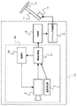
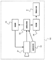
第1実施形態に係る路面区画マーク認識装置1は、走行車線を規定する路面区画マークを認識する装置である。路面区画マーク認識装置1は、例えば車線逸脱防止装置14の一部を構成する。車線逸脱防止装置14は、路面区画マーク認識装置1と、判定部15と、ステアリング制御部12とを備えている。判定部15は、路面区画マーク認識装置1の認識結果に基づいて車両が走行車線から逸脱する可能性を判定する。ステアリング制御部12は、判定部15の判定結果に基づいて、車両が走行車線から逸脱しないようにステアリングを制御する。具体的には、ステアリング制御部12は、ステアリング軸11を回転駆動するパワーステアリングモータ13を制御する。ステアリング制御部12がパワーステアリングモータ13を制御することにより、車線逸脱を防止するようにステアリング軸11に回転トルクが付与される。符号10はステアリングハンドルを示している。
The road surface division
以下、路面区画マーク認識装置1について詳細に説明する。
路面区画マーク認識装置1は、車載カメラ2と、画像処理部3と、温度測定部4と、制限部5とを備える。
Hereinafter, the road surface section
The road surface section
車載カメラ2は、車両前方の路面を撮像する。車載カメラ2は、撮像素子として例えばCCD(Charge Coupled Device)を備えている。車載カメラ2は、例えば、車両のフロントガラスの上部車内側付近に配置されており、フロントガラスを介して車両前方を撮像する。
The in-
温度測定部4は、車載カメラ2の温度を測定する。
The
画像処理部3は、車載カメラ2で撮像した路面画像に基づいて、走行車線を規定する路面区画マーク8を認識する。
本実施形態における路面区画マーク8は、路面上で車両の走行車線を規定するマークであって、一般に車道中央線、車線境界線、車道外側線等と称されるものである。路面区画マーク8の形態としては、例えば、白線、道路鋲、黄色線、石等で表された路面区画線を挙げることができる。白線にも複数の形態があり、例えば、図2(A)に示されるように長く連続する白線、図2(B)に示されるように1〜10メートル程度の線が断続的に続く白線、図2(C)に示されるように丸い点が点線状に続く白線(主として米国で用いられており、ボッツドッツと称される)がある。ここで挙げた白線は、一重線であってもよいし、或いは2本の線が互いに近接して平行に延びる二重線であってもよい。
The
The road
画像処理部3は、路面画像を例えば公知の方法で処理することにより、路面区画マーク8を認識することができる。具体的には、画像処理部3は、路面画像の輝度データに基づいて、周囲と輝度が異なる領域、例えば周囲より輝度が際立って高い領域および周囲より輝度が際立って低い領域の各々のエッジ点分布を算出する。画像処理部3は、算出したエッジ点分布に基づいて、路面の汚れ度合いを算出するとともに路面区画マーク8を認識する。通常、周囲より輝度が際立って高い領域は路面区画マーク8に対応し、周囲より輝度が際立って低い領域は路面の汚れた部分(例えば、コールタール等で補修された部分)に対応する。
The
画像処理部3は、複数の種類の路面区画マーク8にそれぞれ対応する複数の画像処理モードを有している。画像処理部3は、車載カメラ2で撮像した路面画像に含まれる路面区画マーク8の種類を識別し、複数の画像処理モードの中から識別した種類に対応する一つの画像処理モードを選択し、選択された画像処理モードで路面区画マーク8を認識する。画像処理モードとしては、例えば、区画線認識モード、ボッツドッツ認識モードがある。区画線認識モードには、例えば、走行車線の左右両側に路面区画線が存在する場合の認識モードである両側区画線認識モード、走行車線の左側または右側のいずれか一方に路面区画線が存在する場合の認識モードである片側区画線認識モードがある。
The
画像処理モード間で車載カメラ2の使用可能温度域(すなわち、正確に路面区画マーク8を認識できる温度範囲)は異なる。例えば、長く連続する白線を認識するモードでの使用可能温度の上限値は、ボッツドッツを認識するモードでの使用可能温度の上限値よりも高い。これは、長く連続する白線を認識するモードの方が、ボッツドッツを認識するモードよりも、白線認識処理の際に熱ノイズの影響を受け難い(すなわち、熱ノイズに対するロバスト性が高い)からである。
The usable temperature range of the in-
制限部5は、温度測定部4で測定された温度が閾値Th以上である場合に車載カメラ2の動作を制限する。閾値Thは、画像処理モード間で異なる。例えば、画像処理モードがボッツドッツ認識モードである場合の閾値Thは、画像処理モードが区画線認識モードである場合の閾値Thよりも低く設定される。画像処理モード毎に、閾値Thを車載カメラ2の使用可能温度の上限値或いはその近傍に合わせることにより、画像処理モード間で閾値Thを異ならせることができる。
制限部5は、例えば、車載カメラ2への電力供給を制限することにより、車載カメラ2の動作を制限する。車載カメラ2への電力供給を停止すれば、車載カメラ2の動作は停止する。
The
For example, the
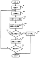
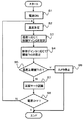
次に、本実施形態に係る路面区画マーク認識装置1の動作について、図3のフローチャートを参照しつつ説明する。
まず、路面区画マーク認識装置1の電源をオンにする(ステップS1)。なお、路面区画マーク認識装置1は、車線逸脱防止装置14等のシステムに組み込まれるものである。よって、通常は、車線逸脱防止装置14等のシステムの電源をオンにすることで、路面区画マーク認識装置1の電源も自動的にオンとなる。
Next, the operation of the road surface section
First, the power of the road surface section
次いで、温度測定部4は、車載カメラ2の温度を測定する(ステップS2)。次いで、車載カメラ2は、車両前方の路面を撮像する(ステップS3)。次いで、画像処理部3は、車載カメラ2で撮像した路面画像に含まれる路面区画マーク8の種類を識別する(ステップS4)。次いで、画像処理部3は、複数の画像処理モードの中から、識別した路面区画マーク8の種類に対応する一つの画像処理モードを選択する(ステップS5)。図3に示される例では、画像処理モードの種類が、区画線認識モード(線状の路面区画マーク8を認識するモード)と、ボッツドッツ認識モード(丸い点が点線状に続く路面区画マーク8を認識するモード)の2種類に設定されているものとする。
Next, the
選択された画像処理モードがボッツドッツ認識モードである場合、ステップS6において閾値Thはボッツドッツ認識モード用の値に設定される。一方、選択された画像処理モードが区画線認識モードである場合、ステップS7において閾値Thは区画線認識モード用の値に設定される。ボッツドッツ認識モード用の閾値Thは、区画線認識モード用の閾値Thよりも低い値である。 If the selected image processing mode is the botsdots recognition mode, the threshold value Th is set to a value for the botsdots recognition mode in step S6. On the other hand, when the selected image processing mode is the lane marking recognition mode, the threshold value Th is set to a value for the lane marking recognition mode in step S7. The threshold Th for the botsdot recognition mode is a value lower than the threshold Th for the lane marking recognition mode.
次いで、画像処理部3は、車載カメラ2の温度が閾値Th以上であるか否かを判断する(ステップS8)。車載カメラ2の温度が閾値Th以上である場合、制限部5は、車載カメラ2への電力供給を停止する(ステップS9)。これにより、車載カメラ2は動作を停止し、路面区画マーク認識装置1は処理を終了する。一方、車載カメラ2の温度が閾値Th未満である場合、画像処理部3は、選択された画像処理モードで路面区画マーク8を認識する(ステップS10)。次いで、路面区画マーク認識装置1の電源がオフにされたかどうかが判断される(ステップS11)。電源がオフにされなかった場合は、ステップS2に戻る。一方、電源がオフにされた場合は、路面区画マーク認識装置1は処理を終了する。通常は、車線逸脱防止装置14等のシステムの電源をオフにすることで、路面区画マーク認識装置1の電源も自動的にオフとなる。以上が、路面区画マーク認識装置1の動作である。
Next, the
以上説明したように、路面区画マーク認識装置1は画像処理モード間で閾値Thを異ならせる。画像処理モード毎に、閾値Thを車載カメラ2の使用可能温度の上限値或いはその近傍に合わせることにより、画像処理モード間で閾値Thを異ならせることができる。これにより、高温下で車載カメラ2を必要以上に停止させずに済み、車載カメラ2の能力を十分に発揮させ、路面区画マーク認識装置1の稼動率を向上させることができる。
As described above, the road surface section
(第2実施形態)
本発明の第2実施形態に係る路面区画マーク認識装置について、図面を参照しつつ説明する。図4は、第2実施形態に係る路面区画マーク認識装置の構成を示すブロック図である。
(Second Embodiment)
A road surface division mark recognition apparatus according to a second embodiment of the present invention will be described with reference to the drawings. FIG. 4 is a block diagram illustrating a configuration of a road surface division mark recognition apparatus according to the second embodiment.
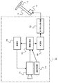
第2実施形態に係る路面区間マーク認識装置20が第1実施形態と異なる点は、画像処理部3が画像処理部21に置換されている点と、制限部5が制限部22に置換されている点であり、その他の構成は第1実施形態と同様である。第1実施形態と同じ構成については、第1実施形態と同じ参照符号を付してその説明を省略する。
The road surface section
第2実施形態における画像処理部21は、車載カメラ2で撮像した路面画像に基づいて、周囲と輝度が異なる領域のエッジ点分布を算出する。さらに、画像処理部21は、算出したエッジ点分布に基づいて、路面の汚れ度合いを算出するとともに路面区画マーク8を認識する。つまり、第2実施形態は、画像処理部21が路面の汚れ具合を算出する点が第1実施形態と異なっている。
The
第2実施形態における制限部22は、温度測定部4で測定された温度が閾値Th2以上である場合に車載カメラ2の動作を制限する。
The
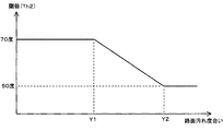
温度測定部4で測定された温度が閾値Th2以上であるか否かは、画像処理部21で判断することができる。閾値Th2は、路面の汚れ度合いに応じて設定される。路面の汚れ度合いが小さい場合の方が、路面の汚れ度合いが大きい場合よりも、路面区画マーク認識処理の際に熱ノイズの影響を受け難い(すなわち、熱ノイズに対するロバスト性が高い)。従って、路面の汚れ度合いが小さい場合には路面の汚れ度合いが大きい場合よりも閾値Th2を高く設定することができる。例えば、図5のグラフに示されるように、路面の汚れ度合いが第1の値Y1になるまでは閾値Th2を一定とし、路面の汚れ度合いがY1を超えると閾値Th2を次第に小さくし、路面の汚れ度合いが第2の値Y2(Y1<Y2)を超えると閾値Th2を一定にすることができる。図5に示される例では、閾値Th2が次第に小さくなる区間において、閾値Th2は一次関数的に減少している。
Whether the temperature measured by the
次に、本実施形態に係る路面区画マーク認識装置20の動作について、図6のフローチャートを参照しつつ説明する。
まず、路面区画マーク認識装置20の電源をオンにする(ステップS1)。なお、路面区画マーク認識装置20は、車線逸脱防止装置14等のシステムに組み込まれるものである。よって、車線逸脱防止装置14等のシステムの電源をオンにすることで、路面区画マーク認識装置20の電源も自動的にオンとなる。
Next, operation | movement of the road surface division
First, the power of the road surface section
次いで、温度測定部4は、車載カメラ2の温度を測定する(ステップS2)。次いで、車載カメラ2は、車両前方の路面を撮像する(ステップS3)。次いで、画像処理部3は、車載カメラ2で撮像した路面画像に基づき、路面の汚れ度合いを算出する(ステップS4)。次いで、画像処理部3は、路面の汚れ度合いに応じて閾値Th2の値を設定する(ステップS5)。
Next, the
次いで、画像処理部3は、車載カメラ2の温度が閾値Th2以上であるか否かを判断する(ステップS6)。車載カメラ2の温度が閾値Th2以上である場合、制限部22は、車載カメラ2への電力供給を停止する(ステップS7)。これにより、車載カメラ2は動作を停止し、路面区画マーク認識装置20は処理を終了する。一方、車載カメラ2の温度が閾値Th2未満である場合、画像処理部3は、路面区画マーク8を認識する(ステップS8)。次いで、路面区画マーク認識装置20の電源がオフにされたかどうかが判断される(ステップS9)。電源がオフにされなかった場合は、ステップS2に戻る。一方、電源がオフにされた場合は、路面区画マーク認識装置20は処理を終了する。車線逸脱防止装置14等のシステムの電源をオフにすることで、路面区画マーク認識装置20の電源も自動的にオフとなる。以上が、路面区画マーク認識装置20の動作である。
Next, the
以上説明したように、路面区画マーク認識装置20では、車載カメラ2の動作を制限するか否かの基準である閾値Th2が、路面の汚れ度合いに応じて設定される。路面の汚れ度合いが小さい場合の方が、路面の汚れ度合いが大きい場合よりも、路面区画マーク認識処理の際に熱ノイズの影響を受け難い。従って、路面の汚れ度合いが小さい場合には路面の汚れ度合いが大きい場合よりも閾値Th2を高く設定することができる。よって、高温下で車載カメラ2を必要以上に停止させずに済み、車載カメラ2の能力を十分に発揮させ、路面区画マーク認識装置20の稼動率を向上させることができる。
As described above, in the road surface section
なお、上記第1〜第2実施形態では路面区画マークが走行車線を規定するマークである場合について説明したが、各実施形態においては路面区画マークが駐車場の駐車区画を規定するマークであってもよい。この場合、路面区画マーク認識装置は、駐車場の駐車区画を認識するための装置となる。 In the first and second embodiments, the road surface division mark is a mark that defines a traveling lane. However, in each embodiment, the road surface division mark is a mark that defines a parking lot of a parking lot. Also good. In this case, the road surface section mark recognizing device is a device for recognizing the parking section of the parking lot.
また、上記第1〜第2実施形態では車載カメラが車両前方の路面を撮像する場合について説明したが、各実施形態においては車載カメラが車両後方や車両側方の路面を撮像してもよい。車載カメラが車両後方の路面を撮像する場合、路面区画マーク認識装置を駐車場の駐車区画を認識する装置とすることができる。 Moreover, although the said 1st-2nd embodiment demonstrated the case where a vehicle-mounted camera imaged the road surface ahead of a vehicle, in each embodiment, a vehicle-mounted camera may image the road surface behind a vehicle or a vehicle side. When the vehicle-mounted camera images the road surface behind the vehicle, the road surface section mark recognition device can be a device that recognizes the parking section of the parking lot.
また、上記第1〜第2実施形態では画像処理部が複数の画像処理モードの中から一つの画像処理モードを選択する場合について説明したが、各実施形態においては複数の画像処理モードの中から一つの画像処理モードをユーザが選択できるよう画像処理部を構成してもよい。すなわち、画像処理部は、車載カメラで撮像した路面画像に含まれる路面区画マークの種類を識別し、複数の画像処理モードの中から識別した路面区画マークに対応する一つの画像処理モードをユーザが選択できるようにし、ユーザが選択した画像処理モードで路面区画マークを認識するように構成されてもよい。この場合、画像処理部が識別した路面区画マークの種類がユーザに表示部等を介して報知され、ユーザは報知された路面区画マークの種類に基づいて当該種類に対応する一つの画像処理モードを選択する。画像処理部は、ユーザに選択された画像処理モードで路面区画マークを認識する。 In the first and second embodiments, the case where the image processing unit selects one image processing mode from a plurality of image processing modes has been described. However, in each embodiment, the image processing unit selects from a plurality of image processing modes. The image processing unit may be configured so that the user can select one image processing mode. That is, the image processing unit identifies the type of road surface division mark included in the road surface image captured by the in-vehicle camera, and the user selects one image processing mode corresponding to the road surface division mark identified from the plurality of image processing modes. The road surface division mark may be recognized in the image processing mode selected by the user. In this case, the type of the road surface division mark identified by the image processing unit is notified to the user via the display unit or the like, and the user selects one image processing mode corresponding to the type based on the notified type of the road surface division mark. select. The image processing unit recognizes the road surface division mark in the image processing mode selected by the user.
<車線逸脱防止装置(第1〜第4実施形態)>
(第1実施形態)
本発明に係る車線逸脱防止装置の第1実施形態について図面を参照しつつ説明する。
図7は、第1実施形態に係る車線逸脱防止装置の構成を示すブロック図である。
<Lane departure prevention device (first to fourth embodiments)>
(First embodiment)
A first embodiment of a lane departure prevention apparatus according to the present invention will be described with reference to the drawings.
FIG. 7 is a block diagram showing the configuration of the lane departure prevention apparatus according to the first embodiment.
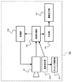
第1実施形態に係る車線逸脱防止装置30は、車両の走行車線逸脱を防止する装置である。
車線逸脱防止装置30は、車載カメラ31と、画像処理部32と、温度測定部33と、制限部34と、判定部35と、ステアリング制御部36とを備える。
The lane
The lane
車載カメラ31は、車両前方の路面を撮像する。車載カメラ31は、撮像素子として例えばCCD(Charge Coupled Device)を備えている。車載カメラ31は、例えば、車両のフロントガラスの上部車内側付近に配置されており、フロントガラスを介して車両前方を撮像する。
The in-
温度測定部33は、車載カメラ31の温度を測定する。
The
画像処理部32は、車載カメラ31で撮像した路面画像に基づいて、走行車線を規定する路面区画マーク8を認識する。
本実施形態における路面区画マーク8は、上記したように、路面上で車両の走行車線を規定するマークであって、一般に車道中央線、車線境界線、車道外側線等と称されるものである。
The
As described above, the road
画像処理部32は、車載カメラ31で撮像した路面画像に基づいて、走行車線を規定する路面区画マーク8を認識する。画像処理部32は、路面画像を例えば公知の方法で処理して路面区画マーク8を認識することができる。具体的には、画像処理部32は、路面画像の輝度データに基づいて、周囲と輝度が異なる領域、例えば周囲より輝度が際立って高い領域のエッジ点分布を算出する。画像処理部3は、算出したエッジ点分布に基づいて、路面区画マーク8を認識する。
The
制限部34は、温度測定部33で測定された温度が閾値Th3以上である場合に車載カメラ31の動作を制限する。制限部34は、例えば、車載カメラ31への電力供給を制限することにより、車載カメラ31の動作を制限する。車載カメラ31への電力供給を停止すれば、車載カメラ31の動作は停止する。
The
判定部35は、画像処理部32の認識結果に基づいて車両が走行車線から逸脱する可能性を判定する。
The
ステアリング制御部36は、判定部35の判定結果に基づいて、車両が走行車線から逸脱しないようにステアリングを制御する。具体的には、ステアリング制御部36は、ステアリング軸11を回転駆動するパワーステアリングモータ13を制御する。ステアリング制御部36がパワーステアリングモータ13を制御することにより、車線逸脱を防止するようにステアリング軸11に回転トルクが付与される。符号10はステアリングハンドルを示している。ステアリング制御部36は、ステアリング軸11に与える回転トルクの制御ゲインGを変化させることにより回転トルクを制御する。制御ゲインGは、ステアリング軸11に与える回転トルクの制御パラメータである。ステアリング軸11に与える回転トルクをTrとしたとき、Trは例えば(式1)で表すことができる。なお、ドライバの操舵力を拡大するパワーステアリング機構については、説明を省略する。
The
Tr=T×G ・・・(式1)
ここで、Tはステアリング制御部36の指示によってステアリング軸11に与えられる回転トルクTrの最大値である。制御ゲインGは、例えば車速やドライバの操舵力に応じて0〜1の間で変化させることができる。具体的には、車速が大きくなるにつれて制御ゲインGを次第に小さくすることができる。これは、車速が大きいときには、少しの回転トルクを付与するだけで、ステアリング制御部36の操舵方向に車両の位置が大きく変位するからである。また、ドライバの操舵力が大きくなるにつれて制御ゲインGを次第に小さくすることができる。これは、ドライバの操舵力が大きいときには、少しの回転トルクを付与するだけで、十分な角度で操舵がなされるからである。なお、車速は車速センサ(図示せず)によって検知され、ドライバの操舵力は操舵力センサ(図示せず)によって検知される。
Tr = T × G (Formula 1)
Here, T is the maximum value of the rotational torque Tr applied to the steering
閾値Th3は、制御ゲインGの大きさに応じて設定される。例えば、制御ゲインGが小さくなるにつれて閾値Th3が次第に高くなるように制御ゲインGは設定される。これは、制御ゲインGが小さくなるにつれて、車載カメラ31が熱ノイズの影響を受けた場合の操舵フィーリングの悪化度合いが小さくなるからである。
The threshold value Th3 is set according to the magnitude of the control gain G. For example, the control gain G is set so that the threshold Th3 gradually increases as the control gain G decreases. This is because as the control gain G decreases, the degree of deterioration of the steering feeling when the in-
次に、本実施形態に係る車線逸脱防止装置30の動作について、図8のフローチャートを参照しつつ説明する。
まず、車線逸脱防止装置30の電源をオンにする(ステップS1)。次いで、温度測定部33は、車載カメラ31の温度を測定する(ステップS2)。次いで、車速やドライバの操舵力に応じて制御ゲインGが設定される(ステップS3)。次いで、制御ゲインGに応じて閾値Th3が設定される(ステップS4)。
Next, operation | movement of the lane
First, the lane
次いで、画像処理部32は、車載カメラ31の温度が閾値Th3以上であるか否かを判断する(ステップS5)。車載カメラ31の温度が閾値Th3以上である場合、制限部34は、車載カメラ31への電力供給を停止する(ステップS6)。これにより、車載カメラ31は動作を停止し、車線逸脱防止装置30は処理を終了する。一方、車載カメラ31の温度が閾値Th3未満である場合、画像処理部32は、路面区画マーク8を認識する(ステップS7)。次いで、車線逸脱防止装置30の電源がオフにされたかどうかが判断される(ステップS8)。電源がオフにされなかった場合は、ステップS2に戻る。一方、電源がオフにされた場合は、車線逸脱防止装置30は処理を終了する。以上が、車線逸脱防止装置30の動作である。
Next, the
以上説明したように、本実施形態によれば、車載カメラ31の動作を制限するか否かの基準である閾値Th3が、制御ゲインGの大きさに応じて設定される。例えば、制御ゲインGが小さくなるにつれて閾値Th3を高く設定することができる。これにより、高温下で車載カメラ31を必要以上に停止させずに済み、車載カメラ31の能力を十分に発揮させ、車線逸脱防止装置30の稼動率を向上させることができる。
As described above, according to the present embodiment, the threshold value Th <b> 3 that is a criterion for determining whether or not to limit the operation of the in-
(第2実施形態)
本発明に係る車線逸脱防止装置の第2実施形態について図面を参照しつつ説明する。
図9は、第2実施形態に係る車線逸脱防止装置の構成を示すブロック図である。
(Second Embodiment)
A second embodiment of the lane departure prevention apparatus according to the present invention will be described with reference to the drawings.
FIG. 9 is a block diagram showing the configuration of the lane departure prevention apparatus according to the second embodiment.
第2実施形態に係る車線逸脱防止装置40が第1実施形態と異なる点は、ステアリング制御部36がなく、警報出力部41が設けられている点であり、その他の構成は第1実施形態と同様である。第1実施形態と同じ構成については、第1実施形態と同じ参照符号を付してその説明を省略する。
The lane
警報出力部41は、判定部35の判定結果に基づいて、車両が走行車線から逸脱する可能性を示す警報を逸脱前に出力する。
Based on the determination result of the
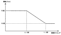
制限部34は、温度測定部33で測定された温度が閾値Th4以上である場合に車載カメラ31の動作を制限する。制限部34は、例えば、車載カメラ31への電力供給を制限することにより、車載カメラ31の動作を制限する。閾値Th4は、警報出力部41に設定された警報タイミングTに応じて設定される。警報タイミングTは、車両が走行車線を逸脱すると予想される時刻の何秒前に警報を出力するかを示す時間である。警報タイミングTは、車速や道路幅に応じて設定することができる。例えば、車速が大きくなるにつれて、警報タイミングTは短く設定される。また、道路幅が狭くなるにつれて、警報タイミングTは短く設定される。警報タイミングTが短くなる(つまり、警報時刻が遅くなる)につれて、路面区画マーク8の認識精度が高くなる。その理由は、警報タイミングTが長い(つまり、警報時刻が早い)場合には、警報タイミングTが短い場合に比べて、より前方の路面情報を取得する必要があるので、ノイズの影響をより多く受けてしまうからである。従って、警報タイミングTが短くなるにつれて閾値Th4を次第に高く設定することができる。
The
図10は、警報タイミングTと閾値Th4の関係の一例を示すグラフである。図10に示される例では、警報タイミングTが0.5秒になるまで閾値Th4は一定であり、警報タイミングTが0.5〜1.0秒になるまでは閾値Th4は次第に低下し、警報タイミングTが1.0秒を超えると閾値Th4は一定になっている。図10に示される例では、警報タイミングTが0.5〜1.0秒の区間で閾値Th4は一次関数的に低下している。 FIG. 10 is a graph showing an example of the relationship between the alarm timing T and the threshold value Th4. In the example shown in FIG. 10, the threshold Th4 is constant until the alarm timing T reaches 0.5 seconds, and the threshold Th4 gradually decreases until the alarm timing T reaches 0.5 to 1.0 seconds. When the timing T exceeds 1.0 seconds, the threshold Th4 is constant. In the example shown in FIG. 10, the threshold value Th <b> 4 decreases in a linear function in the interval where the alarm timing T is 0.5 to 1.0 seconds.
次に、本実施形態に係る車線逸脱防止装置40の動作について、図11のフローチャートを参照しつつ説明する。
まず、車線逸脱防止装置40の電源をオンにする(ステップS1)。次いで、温度測定部33は、車載カメラ31の温度を測定する(ステップS2)。次いで、車速や道路幅に応じて警報タイミングTが設定される(ステップS3)。次いで、警報タイミングTに応じて閾値Th4が設定される(ステップS4)。
Next, operation | movement of the lane
First, the lane
次いで、画像処理部32は、車載カメラ31の温度が閾値Th4以上であるか否かを判断する(ステップS5)。車載カメラ31の温度が閾値Th4以上である場合、制限部34は、車載カメラ31への電力供給を停止する(ステップS6)。これにより、車載カメラ31は動作を停止し、車線逸脱防止装置40は処理を終了する。一方、車載カメラ31の温度が閾値Th4未満である場合、画像処理部32は、路面区画マーク8を認識する(ステップS7)。次いで、車線逸脱防止装置40の電源がオフにされたかどうかが判断される(ステップS8)。電源がオフにされなかった場合は、ステップS2に戻る。一方、電源がオフにされた場合は、車線逸脱防止装置40は処理を終了する。以上が、車線逸脱防止装置40の動作である。
Next, the
以上説明したように、本実施形態によれば、車載カメラ31の動作を制限する基準である閾値Th4が、警報タイミングTに応じて設定される。警報タイミングTが短い場合には、警報タイミングTが長い場合よりも路面区画マーク8の認識精度が高くなる。従って、警報タイミングTが短い場合には警報タイミングTが長い場合よりも閾値Th4を高く設定することができる。よって、高温下で車載カメラ31を必要以上に停止させずに済み、車載カメラ31の能力を十分に発揮させ、車線逸脱防止装置40の稼動率を向上させることができる。
As described above, according to the present embodiment, the threshold value Th4 that is a reference for limiting the operation of the in-
(第3実施形態)
本発明に係る車線逸脱防止装置の第3実施形態について図面を参照しつつ説明する。
図12は、第3実施形態に係る車線逸脱防止装置の構成を示すブロック図である。
(Third embodiment)
A third embodiment of the lane departure prevention apparatus according to the present invention will be described with reference to the drawings.
FIG. 12 is a block diagram showing a configuration of a lane departure prevention apparatus according to the third embodiment.
第3実施形態に係る車線逸脱防止装置50が第1実施形態と異なる点は、制御ゲイン調節部51が設けられている点であり、その他の構成は第1実施形態と同様である。第1実施形態と同じ構成については、第1実施形態と同じ参照符号を付してその説明を省略する。
The lane
制御ゲイン調節部51は、温度測定部33で測定された温度に応じて制御ゲインGを調節する。例えば、車載カメラ31の温度が高くなるにつれて制御ゲインGが小さくなるように、制御ゲインGは調節される。これにより、車載カメラ31が熱ノイズの影響を受けた場合でも、操舵フィーリングを良好な状態に保つことができる。なお、車載カメラ31の動作は制限してもよいし、或いは制限しなくてもよい。
The control
次に、本実施形態に係る車線逸脱防止装置50の動作について、図13のフローチャートを参照しつつ説明する。
まず、車線逸脱防止装置50の電源をオンにする(ステップS1)。次いで、温度測定部33は、車載カメラ31の温度を測定する(ステップS2)。次いで、車速、ドライバの操舵力、および車載カメラ31の温度に応じて制御ゲインGが設定される(ステップS3)。次いで、制御ゲインGに応じて閾値Th5が設定される(ステップS4)。
Next, operation | movement of the lane
First, the lane
次いで、画像処理部32は、車載カメラ31の温度が閾値Th5以上であるか否かを判断する(ステップS5)。車載カメラ31の温度が閾値Th5以上である場合、制限部34は、車載カメラ31への電力供給を停止する(ステップS6)。これにより、車載カメラ31は動作を停止し、車線逸脱防止装置50は処理を終了する。一方、車載カメラ31の温度が閾値Th5未満である場合、画像処理部32は、路面区画マーク8を認識する(ステップS7)。次いで、車線逸脱防止装置50の電源がオフにされたかどうかが判断される(ステップS8)。電源がオフにされなかった場合は、ステップS2に戻る。一方、電源がオフにされた場合は、車線逸脱防止装置50は処理を終了する。以上が、車線逸脱防止装置50の動作である。
Next, the
なお、図13に示される例では閾値Th5を設定し、車載カメラ31の温度が閾値Th5以上である場合に車載カメラ31を停止させたが、本実施形態では、閾値Th5を設定せず、車載カメラ31を制限部34によって停止させなくてもよい。
In the example shown in FIG. 13, the threshold Th5 is set, and the vehicle-mounted
以上説明したように、本実施形態によれば、制御ゲイン調節部51は、車載カメラ31の温度に応じて制御ゲインGを調節する。例えば、車載カメラ31の温度が高くなるにつれて制御ゲインGが小さくなるように、制御ゲインGは調節される。これにより、車載カメラ31が熱ノイズの影響を受けた場合でも、操舵フィーリングを良好な状態に保つことができる。また、高温下で車載カメラ31を必要以上に停止させずに済むので、車線逸脱防止装置50の稼動率を向上させることができる。
As described above, according to the present embodiment, the control
(第4実施形態)
本発明に係る車線逸脱防止装置の第4実施形態について図面を参照しつつ説明する。
図14は、第4実施形態に係る車線逸脱防止装置の構成を示すブロック図である。
(Fourth embodiment)
A fourth embodiment of the lane departure prevention apparatus according to the present invention will be described with reference to the drawings.
FIG. 14 is a block diagram showing the configuration of the lane departure prevention apparatus according to the fourth embodiment.
第4実施形態に係る車線逸脱防止装置60が第2実施形態と異なる点は、タイミング調節部61が設けられている点であり、その他の構成は第2実施形態と同様である。第2実施形態と同じ構成については、第2実施形態と同じ参照符号を付してその説明を省略する。
The lane
タイミング調節部61は、温度測定部33で測定された温度に応じて警報タイミングTを調節する。警報タイミングTが短い場合には、警報タイミングTが長い場合よりも路面区画マーク8の認識精度が高くなる。その理由は、警報タイミングTが長い場合には、警報タイミングTが短い場合に比べて、より前方の路面情報を取得する必要があるので、ノイズの影響をより多く受けてしまうからである。よって、警報タイミングTは、車載カメラ31の温度が高くなるにつれて警報タイミングTが短くなるように調節される。これにより、車載カメラ31が熱ノイズの影響を受けた場合でも、誤警報が出力されるのを防止することができる。
The
次に、本実施形態に係る車線逸脱防止装置60の動作について、図15のフローチャートを参照しつつ説明する。
まず、車線逸脱防止装置60の電源をオンにする(ステップS1)。次いで、温度測定部33は、車載カメラ31の温度を測定する(ステップS2)。次いで、車速、道路幅、および温度測定部33で測定された温度に応じて警報タイミングTが設定される(ステップS3)。次いで、警報タイミングTに応じて閾値Th6が設定される(ステップS4)。
Next, the operation of the lane
First, the lane
次いで、画像処理部32は、車載カメラ31の温度が閾値Th6以上であるか否かを判断する(ステップS5)。車載カメラ31の温度が閾値Th6以上である場合、制限部34は、車載カメラ31への電力供給を停止する(ステップS6)。これにより、車載カメラ31は動作を停止し、車線逸脱防止装置60は処理を終了する。一方、車載カメラ31の温度が閾値Th6未満である場合、画像処理部32は、路面区画マーク8を認識する(ステップS7)。次いで、車線逸脱防止装置60の電源がオフにされたかどうかが判断される(ステップS8)。電源がオフにされなかった場合は、ステップS2に戻る。一方、電源がオフにされた場合は、車線逸脱防止装置60は処理を終了する。以上が、車線逸脱防止装置60の動作である。
Next, the
なお、図13に示される例では閾値Th6を設定し、車載カメラ31の温度が閾値Th6以上である場合に車載カメラ31を停止させたが、本実施形態では、閾値Th6を設定せず、車載カメラ31を制限部34によって停止させなくてもよい。
In the example shown in FIG. 13, the threshold Th6 is set, and the vehicle-mounted
以上説明したように、本実施形態によれば、タイミング調節部61は、車載カメラ31の温度に応じて警報タイミングTを調節する。警報タイミングTが短い場合には、警報タイミングTが長い場合よりも路面区画マーク8の認識精度が高くなる。よって、警報タイミングTは、車載カメラ31の温度が高くなるにつれて警報タイミングTが短くなるように調節される。これにより、車載カメラ31が熱ノイズの影響を受けた場合でも、誤警報が出力されるのを防止することができる。また、高温下で車載カメラ31を必要以上に停止させずに済むので、車線逸脱防止装置60の稼動率を向上させることができる。
As described above, according to the present embodiment, the
本発明は、高温下で使用されることがある白線認識装置および車線逸脱防止装置等に利用可能である。 The present invention is applicable to a white line recognition device and a lane departure prevention device that are sometimes used at high temperatures.
1、20 路面区画マーク認識装置
2、31 車載カメラ
3、21、32 画像処理部
4、33 温度測定部
5、22、34 制限部
6、35 判定部
7、36 ステアリング制御部
8 路面区画マーク
9 車線
10 ステアリング
11 ステアリング軸
30、40、50、60 車線逸脱防止装置
41 警報出力部
51 制御ゲイン調節部
61 タイミング調節部
DESCRIPTION OF
Claims (12)
路面を撮像する車載カメラと、
複数の種類の路面区画マークにそれぞれ対応する複数の画像処理モードを有しており、前記車載カメラで撮像した路面画像に含まれる路面区画マークの種類を識別し、前記複数の画像処理モードの中から識別した路面区画マークに対応する一つの画像処理モードを選択可能にし、選択された画像処理モードで路面区画マークを認識する画像処理部と、
前記車載カメラの温度を測定する温度測定部と、
前記温度測定部で測定された温度が閾値以上である場合に前記車載カメラの動作を制限する制限部とを備え、
前記閾値は、各前記画像処理モード間で異なることを特徴とする路面区画マーク認識装置。 A road surface division mark recognition device for recognizing a road division mark,
An in-vehicle camera that images the road surface;
It has a plurality of image processing modes respectively corresponding to a plurality of types of road surface division marks, identifies types of road surface division marks included in a road surface image captured by the in-vehicle camera, and includes a plurality of image processing modes. An image processing unit that enables selection of one image processing mode corresponding to the road surface division mark identified from the image processing mode, and recognizes the road surface division mark in the selected image processing mode;
A temperature measuring unit for measuring the temperature of the in-vehicle camera;
A limiting unit that limits the operation of the in-vehicle camera when the temperature measured by the temperature measuring unit is equal to or higher than a threshold value,
The road surface section mark recognition apparatus, wherein the threshold value is different between the image processing modes.
路面を撮像する車載カメラと、
前記車載カメラで撮像した路面画像に基づいて、周囲と輝度が異なる領域のエッジ点分布を算出し、算出したエッジ点分布に基づいて、路面の汚れ度合いを算出するとともに路面区画マークを認識する画像処理部と、
前記車載カメラの温度を測定する温度測定部と、
前記温度測定部で測定された温度が閾値以上である場合に前記車載カメラの動作を制限する制限部とを備え、
前記閾値は、前記路面の汚れ度合いに応じて設定されることを特徴とする路面区画マーク認識装置。 A road surface division mark recognition device for recognizing a road division mark,
An in-vehicle camera that images the road surface;
An image that recognizes road surface division marks and calculates the degree of dirt on the road surface based on the calculated edge point distribution, based on the road surface image captured by the in-vehicle camera. A processing unit;
A temperature measuring unit for measuring the temperature of the in-vehicle camera;
A limiting unit that limits the operation of the in-vehicle camera when the temperature measured by the temperature measuring unit is equal to or higher than a threshold value,
The road surface section mark recognition apparatus, wherein the threshold value is set according to a degree of dirt on the road surface.
路面を撮像する車載カメラと、
前記車載カメラで撮像した路面画像に基づいて、走行車線を規定する路面区画マークを認識する画像処理部と、
前記車載カメラの温度を測定する温度測定部と、
前記温度測定部で測定された温度が閾値以上である場合に前記車載カメラの動作を制限する制限部と、
前記画像処理部の認識結果に基づいて車両が走行車線から逸脱する可能性を判定する判定部と、
前記判定部の判定結果に基づいて、車両が走行車線から逸脱しないようにステアリングを制御するステアリング制御部とを備え、
前記ステアリング制御部は、ステアリング軸に与える回転トルクの制御ゲインを変化させることによりステアリングを制御し、
前記閾値は、前記制御ゲインの大きさに応じて設定されることを特徴とする車線逸脱防止装置。 A lane departure prevention device for preventing a lane departure of a vehicle,
An in-vehicle camera that images the road surface;
Based on the road surface image captured by the in-vehicle camera, an image processing unit for recognizing a road surface division mark that defines a traveling lane;
A temperature measuring unit for measuring the temperature of the in-vehicle camera;
A limiting unit that limits the operation of the in-vehicle camera when the temperature measured by the temperature measuring unit is equal to or higher than a threshold;
A determination unit that determines a possibility that the vehicle deviates from the driving lane based on the recognition result of the image processing unit;
A steering control unit that controls steering so that the vehicle does not deviate from the driving lane based on the determination result of the determination unit;
The steering control unit controls the steering by changing the control gain of the rotational torque applied to the steering shaft,
The lane departure prevention apparatus according to claim 1, wherein the threshold value is set according to a magnitude of the control gain.
路面を撮像する車載カメラと、
前記車載カメラで撮像した路面画像に基づいて、走行車線を規定する路面区画マークを認識する画像処理部と、
前記車載カメラの温度を測定する温度測定部と、
前記温度測定部で測定された温度が閾値以上である場合に前記車載カメラの動作を制限する制限部と、
前記画像処理部の認識結果に基づいて車両が走行車線から逸脱する可能性を判定する判定部と、
前記判定部の判定結果に基づいて、逸脱する可能性を示す警報を逸脱前に出力する警報出力部とを備え、
前記閾値は、前記警報出力部に設定された警報タイミングに応じて設定されることを特徴とする車線逸脱防止装置。 A lane departure prevention device for preventing a lane departure of a vehicle,
An in-vehicle camera that images the road surface;
Based on the road surface image captured by the in-vehicle camera, an image processing unit for recognizing a road surface division mark that defines a traveling lane;
A temperature measuring unit for measuring the temperature of the in-vehicle camera;
A limiting unit that limits the operation of the in-vehicle camera when the temperature measured by the temperature measuring unit is equal to or higher than a threshold;
A determination unit that determines a possibility that the vehicle deviates from the driving lane based on the recognition result of the image processing unit;
Based on the determination result of the determination unit, an alarm output unit that outputs an alarm indicating the possibility of departure before departure,
The lane departure prevention apparatus according to claim 1, wherein the threshold value is set according to an alarm timing set in the alarm output unit.
路面を撮像する車載カメラと、
前記車載カメラで撮像した路面画像に基づいて、走行車線を規定する路面区画マークを認識する画像処理部と、
前記車載カメラの温度を測定する温度測定部と、
前記画像処理部の認識結果に基づいて車両が走行車線から逸脱する可能性を判定する判定部と、
前記判定部の判定結果に基づいて、車両が走行車線から逸脱しないようにステアリングを制御するステアリング制御部とを備え、
前記ステアリング制御部は、ステアリング軸に与える回転トルクの制御ゲインを変化させることによりステアリングを制御し、
前記車線逸脱防止装置は、
前記温度測定部で測定された温度に応じて前記制御ゲインを調節する制御ゲイン調節部をさらに備えることを特徴とする車線逸脱防止装置。 A lane departure prevention device for preventing a lane departure of a vehicle,
An in-vehicle camera that images the road surface;
Based on the road surface image captured by the in-vehicle camera, an image processing unit for recognizing a road surface division mark that defines a traveling lane;
A temperature measuring unit for measuring the temperature of the in-vehicle camera;
A determination unit that determines a possibility that the vehicle deviates from the driving lane based on the recognition result of the image processing unit;
A steering control unit that controls steering so that the vehicle does not deviate from the driving lane based on the determination result of the determination unit;
The steering control unit controls the steering by changing the control gain of the rotational torque applied to the steering shaft,
The lane departure prevention device is:
A lane departure prevention apparatus, further comprising a control gain adjusting unit that adjusts the control gain according to the temperature measured by the temperature measuring unit.
路面を撮像する車載カメラと、
前記車載カメラで撮像した路面画像に基づいて、走行車線を規定する路面区画マークを認識する画像処理部と、
前記車載カメラの温度を測定する温度測定部と、
前記画像処理部の認識結果に基づいて車両が走行車線から逸脱する可能性を判定する判定部と、
前記判定部の判定結果に基づいて、逸脱する可能性を示す警報を出力する警報出力部とを備え、
前記車線逸脱防止装置は、
前記温度測定部で測定された温度に応じて前記警報タイミングを調節するタイミング調節部をさらに備えることを特徴とする車線逸脱防止装置。 A lane departure prevention device for preventing a lane departure of a vehicle,
An in-vehicle camera that images the road surface;
Based on the road surface image captured by the in-vehicle camera, an image processing unit for recognizing a road surface division mark that defines a traveling lane;
A temperature measuring unit for measuring the temperature of the in-vehicle camera;
A determination unit that determines a possibility that the vehicle deviates from the driving lane based on the recognition result of the image processing unit;
Based on the determination result of the determination unit, an alarm output unit that outputs an alarm indicating the possibility of departure,
The lane departure prevention device is:
A lane departure prevention apparatus, further comprising a timing adjustment unit that adjusts the alarm timing according to the temperature measured by the temperature measurement unit.
前記タイミング調節部は、前記温度が高くなるにつれて前記警報タイミングを次第に短くすることを特徴とする請求項11に記載の車線逸脱防止装置。 The alarm timing is a time indicating how many seconds before the time when the vehicle is expected to depart from the driving lane,
The lane departure prevention apparatus according to claim 11, wherein the timing adjustment unit gradually shortens the warning timing as the temperature increases.
Priority Applications (4)
| Application Number | Priority Date | Filing Date | Title |
|---|---|---|---|
| JP2008229938A JP4849346B2 (en) | 2008-09-08 | 2008-09-08 | Road section mark recognition device and lane departure prevention device |
| US12/554,434 US8265872B2 (en) | 2008-09-08 | 2009-09-04 | Road surface division mark recognition apparatus, and lane departure prevention apparatus |
| DE102009029243A DE102009029243B4 (en) | 2008-09-08 | 2009-09-07 | Lane separation mark recognition device and lane departure prevention device |
| US13/564,078 US8392115B2 (en) | 2008-09-08 | 2012-08-01 | Road surface division mark recognition apparatus, and lane departure prevention apparatus |
Applications Claiming Priority (1)
| Application Number | Priority Date | Filing Date | Title |
|---|---|---|---|
| JP2008229938A JP4849346B2 (en) | 2008-09-08 | 2008-09-08 | Road section mark recognition device and lane departure prevention device |
Publications (2)
| Publication Number | Publication Date |
|---|---|
| JP2010064513A true JP2010064513A (en) | 2010-03-25 |
| JP4849346B2 JP4849346B2 (en) | 2012-01-11 |
Family
ID=41795211
Family Applications (1)
| Application Number | Title | Priority Date | Filing Date |
|---|---|---|---|
| JP2008229938A Active JP4849346B2 (en) | 2008-09-08 | 2008-09-08 | Road section mark recognition device and lane departure prevention device |
Country Status (3)
| Country | Link |
|---|---|
| US (2) | US8265872B2 (en) |
| JP (1) | JP4849346B2 (en) |
| DE (1) | DE102009029243B4 (en) |
Cited By (7)
| Publication number | Priority date | Publication date | Assignee | Title |
|---|---|---|---|---|
| JP2012103748A (en) * | 2010-11-05 | 2012-05-31 | Denso Corp | Road section line recognition device |
| WO2013161389A1 (en) * | 2012-04-26 | 2013-10-31 | 株式会社デンソー | Vehicle-mounted camera control device |
| JP2014512303A (en) * | 2011-04-14 | 2014-05-22 | コンティ テミック マイクロエレクトロニック ゲゼルシャフト ミット ベシュレンクテル ハフツング | Detection of ice on vehicle glass by internal temperature sensor |
| WO2014148324A1 (en) * | 2013-03-22 | 2014-09-25 | 株式会社デンソー | Vehicle control device |
| KR101827707B1 (en) * | 2016-05-24 | 2018-03-22 | 현대자동차주식회사 | Apparatus of camera for vehicle, vehicle having the same and controlling method of camera for vehicle |
| KR20210004917A (en) * | 2014-03-31 | 2021-01-13 | 팅크웨어(주) | Electronic apparatus and control method thereof |
| WO2021044456A1 (en) * | 2019-09-02 | 2021-03-11 | 三菱電機株式会社 | Power control device and power control method for vehicle-mounted camera |
Families Citing this family (13)
| Publication number | Priority date | Publication date | Assignee | Title |
|---|---|---|---|---|
| JP4708443B2 (en) | 2008-01-31 | 2011-06-22 | トヨタ自動車株式会社 | Operation control map and white line recognition device |
| JP4992990B2 (en) * | 2010-02-24 | 2012-08-08 | 株式会社デンソー | Lane marking detector |
| ES2402422B1 (en) * | 2011-09-07 | 2014-03-11 | Manuel MUÑOZ SÁIZ | AUTOMATIC DRIVING SYSTEM AND IMPROVED VELOCITY ZONE WARNING SYSTEMS FOR IMPROVED VEHICLES |
| DE102012005400A1 (en) * | 2012-03-16 | 2013-09-19 | Connaught Electronics Ltd. | Camera system for motor vehicle, has switching device, which is connected between image sensor of camera and image processing unit to receive information, different from images, based on operating parameter of camera |
| KR20140044970A (en) | 2012-09-13 | 2014-04-16 | 한국전자통신연구원 | Method and apparatus for controlling blocking of service attack by using access control list |
| KR20140047894A (en) * | 2012-10-15 | 2014-04-23 | 현대모비스 주식회사 | Warning apparatus and method for reducing car body vibration |
| DE102012024658A1 (en) * | 2012-12-17 | 2014-06-18 | Connaught Electronics Ltd. | Method for switching of camera e.g. vehicle-mounted camera of motor vehicle, involves performing switching of camera between two operating modes, based on current value of temperature of camera image sensor |
| DE102014106034B4 (en) * | 2014-04-30 | 2022-02-10 | Connaught Electronics Ltd. | Method for setting an image sensor of a vehicle camera of a motor vehicle into an image recording state, camera system and motor vehicle |
| JP6303974B2 (en) | 2014-10-22 | 2018-04-04 | 株式会社デンソー | In-vehicle camera device and in-vehicle system |
| CN205249352U (en) * | 2014-12-17 | 2016-05-18 | 日本电产科宝株式会社 | Vehicle -mounted image recognition device |
| US9443426B1 (en) | 2015-11-13 | 2016-09-13 | Byron Paul Formwalt | Method and device for sensing traffic flow and notifying motor vehicle drivers of the same |
| DE102017208663A1 (en) * | 2016-06-09 | 2017-12-14 | Conti Temic Microelectronic Gmbh | Environment sensing device and motor vehicle with such an environment sensing device |
| CN106971144B (en) * | 2017-02-28 | 2020-06-16 | 北京航空航天大学 | Method for extracting road center line by applying Visual Graph algorithm |
Citations (4)
| Publication number | Priority date | Publication date | Assignee | Title |
|---|---|---|---|---|
| JP2001088609A (en) * | 1999-09-22 | 2001-04-03 | Fuji Heavy Ind Ltd | Power supply controlling method of on-vehicle camera device therefor |
| JP2003228711A (en) * | 2001-11-30 | 2003-08-15 | Hitachi Ltd | Lane mark recognition method |
| JP2008030619A (en) * | 2006-07-28 | 2008-02-14 | Toyota Motor Corp | Kinds-of-road-division-line sorting system and road-division-line recognition sytem |
| JP2008165610A (en) * | 2006-12-28 | 2008-07-17 | Toyota Motor Corp | Road section line recognition device |
Family Cites Families (12)
| Publication number | Priority date | Publication date | Assignee | Title |
|---|---|---|---|---|
| JP3346189B2 (en) * | 1996-10-24 | 2002-11-18 | トヨタ自動車株式会社 | Vehicle momentum detection device |
| JP2002090851A (en) | 2000-09-20 | 2002-03-27 | Eastman Kodak Japan Ltd | Electronic camera |
| JP2002320126A (en) | 2001-04-23 | 2002-10-31 | Mitsubishi Electric Corp | On-vehicle imaging system |
| JP4327389B2 (en) | 2001-10-17 | 2009-09-09 | 株式会社日立製作所 | Travel lane recognition device |
| EP1504276B1 (en) * | 2002-05-03 | 2012-08-08 | Donnelly Corporation | Object detection system for vehicle |
| US6759949B2 (en) * | 2002-05-23 | 2004-07-06 | Visteon Global Technologies, Inc. | Image enhancement in far infrared camera |
| JP4772115B2 (en) * | 2005-05-31 | 2011-09-14 | コーニンクレッカ フィリップス エレクトロニクス エヌ ヴィ | Method and system for detecting roads at night |
| JP2007300368A (en) | 2006-04-28 | 2007-11-15 | Fujifilm Corp | Solid-state imaging device |
| US7786898B2 (en) * | 2006-05-31 | 2010-08-31 | Mobileye Technologies Ltd. | Fusion of far infrared and visible images in enhanced obstacle detection in automotive applications |
| JP4708443B2 (en) * | 2008-01-31 | 2011-06-22 | トヨタ自動車株式会社 | Operation control map and white line recognition device |
| US20100020170A1 (en) * | 2008-07-24 | 2010-01-28 | Higgins-Luthman Michael J | Vehicle Imaging System |
| CN102834309B (en) * | 2010-02-26 | 2016-12-21 | 金泰克斯公司 | Automotive vehicle monitoring of tools, warning and control system |
-
2008
- 2008-09-08 JP JP2008229938A patent/JP4849346B2/en active Active
-
2009
- 2009-09-04 US US12/554,434 patent/US8265872B2/en active Active
- 2009-09-07 DE DE102009029243A patent/DE102009029243B4/en active Active
-
2012
- 2012-08-01 US US13/564,078 patent/US8392115B2/en active Active
Patent Citations (4)
| Publication number | Priority date | Publication date | Assignee | Title |
|---|---|---|---|---|
| JP2001088609A (en) * | 1999-09-22 | 2001-04-03 | Fuji Heavy Ind Ltd | Power supply controlling method of on-vehicle camera device therefor |
| JP2003228711A (en) * | 2001-11-30 | 2003-08-15 | Hitachi Ltd | Lane mark recognition method |
| JP2008030619A (en) * | 2006-07-28 | 2008-02-14 | Toyota Motor Corp | Kinds-of-road-division-line sorting system and road-division-line recognition sytem |
| JP2008165610A (en) * | 2006-12-28 | 2008-07-17 | Toyota Motor Corp | Road section line recognition device |
Cited By (14)
| Publication number | Priority date | Publication date | Assignee | Title |
|---|---|---|---|---|
| JP2012103748A (en) * | 2010-11-05 | 2012-05-31 | Denso Corp | Road section line recognition device |
| US9330552B2 (en) | 2011-04-14 | 2016-05-03 | Conti Temic Microelectronic Gmbh | Detection of ice on a vehicle window by means of an internal temperature sensor |
| JP2014512303A (en) * | 2011-04-14 | 2014-05-22 | コンティ テミック マイクロエレクトロニック ゲゼルシャフト ミット ベシュレンクテル ハフツング | Detection of ice on vehicle glass by internal temperature sensor |
| JP2013226974A (en) * | 2012-04-26 | 2013-11-07 | Denso Corp | Vehicle mounted camera control device |
| WO2013161389A1 (en) * | 2012-04-26 | 2013-10-31 | 株式会社デンソー | Vehicle-mounted camera control device |
| US10554884B2 (en) | 2012-04-26 | 2020-02-04 | Denso Corporation | In-vehicle camera control device |
| WO2014148324A1 (en) * | 2013-03-22 | 2014-09-25 | 株式会社デンソー | Vehicle control device |
| JP2014187497A (en) * | 2013-03-22 | 2014-10-02 | Denso Corp | Vehicle controller |
| US9421974B2 (en) | 2013-03-22 | 2016-08-23 | Denso Corporation | Vehicle controller |
| KR20210004917A (en) * | 2014-03-31 | 2021-01-13 | 팅크웨어(주) | Electronic apparatus and control method thereof |
| KR102299500B1 (en) | 2014-03-31 | 2021-09-09 | 현대자동차주식회사 | Electronic apparatus and control method thereof |
| KR101827707B1 (en) * | 2016-05-24 | 2018-03-22 | 현대자동차주식회사 | Apparatus of camera for vehicle, vehicle having the same and controlling method of camera for vehicle |
| WO2021044456A1 (en) * | 2019-09-02 | 2021-03-11 | 三菱電機株式会社 | Power control device and power control method for vehicle-mounted camera |
| JPWO2021044456A1 (en) * | 2019-09-02 | 2021-11-25 | 三菱電機株式会社 | Power control device and power control method for in-vehicle cameras |
Also Published As
| Publication number | Publication date |
|---|---|
| US20120293657A1 (en) | 2012-11-22 |
| DE102009029243B4 (en) | 2013-04-25 |
| US20100060738A1 (en) | 2010-03-11 |
| US8392115B2 (en) | 2013-03-05 |
| JP4849346B2 (en) | 2012-01-11 |
| DE102009029243A1 (en) | 2010-04-08 |
| US8265872B2 (en) | 2012-09-11 |
Similar Documents
| Publication | Publication Date | Title |
|---|---|---|
| JP4849346B2 (en) | Road section mark recognition device and lane departure prevention device | |
| JP5462609B2 (en) | Stop line recognition device | |
| US9340227B2 (en) | Vehicle lane keep assist system | |
| JP2005326963A5 (en) | ||
| JP2007221200A (en) | Vehicle periphery monitoring system | |
| JP2011180982A (en) | Lane marker detecting apparatus | |
| JP6478414B2 (en) | Vehicle control device, vehicle control method, and vehicle control program | |
| JP2008250904A (en) | Traffic lane division line information detecting device, travel traffic lane maintaining device, and traffic lane division line recognizing method | |
| JP2009217492A (en) | Lane marking recognition device, lane maintenance support device, and lane marking recognition method | |
| JP2010019589A (en) | Inter-vehicle distance detector, drive recorder apparatus | |
| US20100277298A1 (en) | Detection system and method thereof | |
| US20190202459A1 (en) | Method for Controlling Travel and Device for Controlling Travel of Vehicle | |
| JP2005157670A (en) | White line detecting device | |
| JP2004310522A (en) | Vehicular image processor | |
| JP2007264717A5 (en) | ||
| JP5316392B2 (en) | Driving assistance device | |
| JP2010018164A (en) | Vehicular drive supporting device | |
| US20200128165A1 (en) | Method for Predictable Exposure Control of at Least One First Vehicle Camera | |
| KR101601500B1 (en) | System and Method for assisting vehicle driving for using smartphone | |
| JP2010020710A (en) | Device for detecting road side fixed object | |
| JP2007038773A (en) | On-vehicle camera inspection device | |
| JP2005033680A (en) | Image processing apparatus for vehicle | |
| JP2004221871A (en) | Device for monitoring periphery of vehicle | |
| JP2009140023A (en) | Vehicle obstacle detection unit | |
| JP6281435B2 (en) | Parking assistance system |
Legal Events
| Date | Code | Title | Description |
|---|---|---|---|
| A977 | Report on retrieval |
Free format text: JAPANESE INTERMEDIATE CODE: A971007 Effective date: 20100617 |
|
| A131 | Notification of reasons for refusal |
Free format text: JAPANESE INTERMEDIATE CODE: A131 Effective date: 20100722 |
|
| A521 | Request for written amendment filed |
Free format text: JAPANESE INTERMEDIATE CODE: A523 Effective date: 20100913 |
|
| A131 | Notification of reasons for refusal |
Free format text: JAPANESE INTERMEDIATE CODE: A131 Effective date: 20110329 |
|
| RD02 | Notification of acceptance of power of attorney |
Free format text: JAPANESE INTERMEDIATE CODE: A7422 Effective date: 20110901 |
|
| TRDD | Decision of grant or rejection written | ||
| A01 | Written decision to grant a patent or to grant a registration (utility model) |
Free format text: JAPANESE INTERMEDIATE CODE: A01 Effective date: 20110922 |
|
| A01 | Written decision to grant a patent or to grant a registration (utility model) |
Free format text: JAPANESE INTERMEDIATE CODE: A01 |
|
| A61 | First payment of annual fees (during grant procedure) |
Free format text: JAPANESE INTERMEDIATE CODE: A61 Effective date: 20111005 |
|
| R151 | Written notification of patent or utility model registration |
Ref document number: 4849346 Country of ref document: JP Free format text: JAPANESE INTERMEDIATE CODE: R151 |
|
| FPAY | Renewal fee payment (event date is renewal date of database) |
Free format text: PAYMENT UNTIL: 20141028 Year of fee payment: 3 |