JP2010061372A - Information processor, pointer designation method, and program - Google Patents
Information processor, pointer designation method, and program Download PDFInfo
- Publication number
- JP2010061372A JP2010061372A JP2008226096A JP2008226096A JP2010061372A JP 2010061372 A JP2010061372 A JP 2010061372A JP 2008226096 A JP2008226096 A JP 2008226096A JP 2008226096 A JP2008226096 A JP 2008226096A JP 2010061372 A JP2010061372 A JP 2010061372A
- Authority
- JP
- Japan
- Prior art keywords
- contact
- logical
- point
- designated point
- coordinates
- Prior art date
- Legal status (The legal status is an assumption and is not a legal conclusion. Google has not performed a legal analysis and makes no representation as to the accuracy of the status listed.)
- Granted
Links
Images


Abstract
Description
本発明は、接触を検出可能な接触検出手段を有する情報処理装置、及び、当該情報処理装置で用いられるプログラム及びポインタの指定方法に関する。 The present invention relates to an information processing apparatus having contact detection means capable of detecting contact, a program used in the information processing apparatus, and a pointer designation method.
昨今、様々な情報処理装置に、タッチパネル又はタッチスクリーンと呼ばれる接触検出部が設けられている。前記情報処理装置では、接触検出部を接触検出手段として用い、OS(Operating System)やアプリケーション等のソフトウェアに対して、ポインタが指し示す座標を通知している。 Recently, various information processing apparatuses are provided with a touch detection unit called a touch panel or a touch screen. In the information processing apparatus, a contact detection unit is used as contact detection means, and the coordinates indicated by the pointer are notified to software such as an OS (Operating System) and an application.
関連する技術としては、PDA(Personal Digital Assistants)や携帯端末等で利用されるタッチパネルでの座標指定方式の指定精度を上げる技術が挙げられる。指定精度を上げる方法としては、例えばGUI(Graphical User Interface)上で指定対象となるアイコン等のサイズを大きくし、指定可能箇所の面積を増やすといった方法や、スタイラスの様な先端の細い器具により座標を指定する、或いは指に接点の小さくなる突起のついたシールを貼る等により、画面との接触面積を小さくすることによって、入力位置の精度を向上する方法が取られている。 As a related technique, there is a technique for increasing the designation accuracy of a coordinate designation method on a touch panel used in PDA (Personal Digital Assistants), a portable terminal, or the like. As a method of increasing the specified accuracy, for example, the size of an icon or the like to be specified on the GUI (Graphical User Interface) is increased, and the area of the specifiable portion is increased, or the coordinates are adjusted by a tool having a thin tip such as a stylus. The method of improving the accuracy of the input position is taken by reducing the contact area with the screen, for example, by designating or sticking a sticker with a protrusion with a small contact point on the finger.
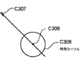
また、別の一例として、特許文献1に記載されている情報処理装置が挙げられる。特許文献1に記載されている情報処理装置は、タッチポインティング手段と、それ以外のマウスポインタのいずれの入力であるかを判別する判別手段と、タッチポインティング手段による位置指定時(座標指定時)に、図8に示す様な環状部と矢印部とを組み合わせた定型の特殊なカーソルC308を用いて、タッチポインティング手段への接触である物理入力点C306を、当該カーソルC308の指示先座標C307にエミュレートする表示制御手段で構成されている。動作は、タッチポインタによる座標指定であるかどうかを判別手段により判定し、タッチポインタでの入力である場合に、前記したカーソルC308を読み出して表示すると共に、物理入力点C306からカーソルC308の長さを加算(減算)した座標(論理的入力点)を算出して利用する。
Another example is an information processing apparatus described in
また、別の関連する技術としては、特許文献2に記載されたコンピュータ入力装置が挙げられる。特許文献2には、タブレットへの入力(接触)から、入力座標と接触面積を夫々算出する手段を有するコンピュータ入力装置が記載されている。
Another related technique is the computer input device described in
しかしながら、上述した技術は、未だ使用者の所望する座標指定の精度に課題を残している。 However, the above-described technique still has a problem in the accuracy of coordinate designation desired by the user.
即ち、特許文献1に記載された技術を用いた場合は、必ずしも物理入力点と論理入力点を分ける必要の無いケースであっても、物理入力点と離間した論理入力点が設定されてしまい、逆に操作性が悪くなるケースがある。
That is, when the technique described in
その理由は、このような定型カーソルを読み出すためのトリガがタッチポインタによる入力であるかどうかの判定によるものであり、指の他にスタイラス等の様な先端の細い器具による入力を併用するケースを想定していないため、例えばタッチポインタをスタイラスの様に先端の細い器具で操作するケースでは、無駄に指定座標と異なる座標を指定する事になるためである。 The reason is that it is based on the determination of whether or not the trigger for reading such a fixed cursor is input by a touch pointer, and in addition to a finger, input by an instrument with a thin tip such as a stylus is also used. This is because, for example, in the case where the touch pointer is operated with a tool having a thin tip such as a stylus, coordinates different from the designated coordinates are designated unnecessarily.
また第2の問題点は、同様に特許文献1の方式では、アプリケーションがその動作によってカーソル形状を変化させるケースにおいて、意図した動作をしない可能性がある。
Similarly, the second problem is that, in the method of
その理由は、特許文献1によれば、座標指定時にカーソル形状を通常のものと変更し、物理入力点とカーソル形状から定まる一定間隔離間した論理入力点の両方を表示する定形カーソルを表示するため、アプリケーションが動作状態、たとえば入力モード等の指定によりカーソル形状を例えば矢印から指状に変更していても、それらのカーソル形状を定型カーソルに変えてしまう事により、入力状態が判別出来なくなるためである。
The reason is that, according to
また第3の問題点は、特許文献1の方式では、指定座標によっては必ずしも意図した表示位置に定形カーソルが来ない問題点がある。その理由は、該当文献によればカーソルの方向を表示位置によって決定、もしくは設定やボタン等により方向を変更しない設定となっているため、例えば右上に指がある状態で指の左側の座標を指定したい場合等に意図した指定が行えない可能性がある。
The third problem is that the standard cursor does not always come to the intended display position depending on the designated coordinates in the method of
本発明の目的は、接触検出手段を有する情報処理装置において、物理指定点と異なる論理指定点を算出処理して指定点を可視可能にしつつ、所望の指定位置を選択可能とできる情報処理装置を提供することにある。 An object of the present invention is to provide an information processing apparatus capable of selecting a desired designated position while making the designated point visible by calculating a logical designated point different from the physical designated point in an information processing apparatus having contact detection means. It is to provide.
本発明の情報処理装置は、接触された座標及び面積を検出可能な接触検出手段と、前記接触検出手段で検出した座標及び面積に基づいて物理指定点を算出する手段と、前記接触検出手段で検出した座標及び面積と前記物理指定点とから論理指定点を算出する手段と、前記算出した論理指定点を入力座標としてOS及び/又はアプリケーションプログラムに通知する手段とを備えることを特徴とする。 An information processing apparatus according to the present invention includes a contact detection unit capable of detecting a contact coordinate and an area, a unit for calculating a physical designated point based on the coordinate and area detected by the contact detection unit, and the contact detection unit. It comprises means for calculating a logical designated point from detected coordinates and area and the physical designated point, and means for notifying the calculated logical designated point as input coordinates to an OS and / or an application program.
本発明によれば、接触検出手段を有する情報処理装置において、物理指定点と異なる論理指定点を算出処理して指定点を可視可能にしつつ、所望の指定位置を選択可能とできる。 According to the present invention, in an information processing apparatus having contact detection means, it is possible to select a desired designated position while making a designated point visible by calculating a logical designated point different from the physical designated point.
次に、発明を実施するための最良の形態について図面を参照して詳細に説明する。 Next, the best mode for carrying out the invention will be described in detail with reference to the drawings.
図1は、第1の実施の形態の構成を示す機能ブロック図である。図2は、第1の実施の形態の構成における接触検出部と指との平面的位置関係示す説明図である。図3は、接触検出部とスタイラスとの平面的位置関係示す説明図である。 FIG. 1 is a functional block diagram showing the configuration of the first embodiment. FIG. 2 is an explanatory diagram illustrating a planar positional relationship between the contact detection unit and the finger in the configuration of the first embodiment. FIG. 3 is an explanatory diagram illustrating a planar positional relationship between the contact detection unit and the stylus.
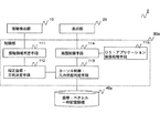
図1を参照すると、本発明の第1の実施の形態の情報処理装置1は、接触検出部10、表示部20、制御部30および、座標・ベクトル一時記憶領域40を含んで構成される。また、制御部30は、接触領域判定手段101、指定座標決定手段102、画面制御手段103および、OS・アプリケーション画面処理手段104として、少なくとも機能する。
Referring to FIG. 1, the
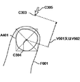
図2の記載を説明すると、C301はカーソル、C303は論理指定点、C304は物理指定点、F601は指、A401は接触検出部10が指F601によって接触された接触領域を示している。また、V501は、物理指定点C304および接触領域A401から論理指定点C303を算出するためのオフセットベクトルである。尚、オフセットベクトルV501の算出は、後に詳説する。
Referring to FIG. 2, C301 is a cursor, C303 is a logical designated point, C304 is a physical designated point, F601 is a finger, and A401 is a contact area where the
図3の記載を説明すると、C301はカーソル、C302は論理指定点、F201はスタイラスを示している。 Referring to FIG. 3, C301 indicates a cursor, C302 indicates a logical designated point, and F201 indicates a stylus.
接触検出部10は、接触表面上に何らかの入力器具や指等の接触を検出して、接触された座標及び面積を検出可能とするデバイスである。接触検出部10は、タッチパネルやタッチスクリーン等を用いれば良い。尚、接触検出部10は、画像を表示する表示部20の表示面上、もしくは同一面上に物理的に配置、もしくは形成されるもので、本特許の対象とする接触検出手段を、例えば液晶ディスプレイ等の画素の素子毎、もしくはそれに準ずる密度で光学センサや圧力センサを用いて実現すれば良い。また、接触検出手段は、時系列等で接触をスキャンする等により、複数のセンサで同時に接触を検出する事を可能とする。
The
表示部20は、制御部30の画面制御手段103によって生成された表示情報を実際に表示するデバイスである。
The
制御部30は、上記の各情報を演算処理もしくは制御する手段101、102、103、104を、実際に実行する物理装置である。
The
座標・ベクトル一時記憶領域40は、記憶部に設けられ、指定座標決定手段102から出力される物理指定点C304、論理指定点C303、オフセットベクトルV501の情報を、一定時間記憶する記憶領域である。
The coordinate / vector
接触領域判定手段101は、指F601等によって接触された接触領域A401に関する信号を、接触検出部10から読み込み、接触領域A401の面積及び位置情報を領域範囲情報として、指定座標決定手段102に通知する。
The contact
指定座標決定手段102は、接触領域判定手段101から通知される接触領域A401の領域範囲情報に基づき、当該領域の中心点である物理指定点C304の座標を判定処理し、さらに接触領域A401の接触面積を用いてオフセットベクトルV501を算出処理し、論理指定点C303(座標情報)を算出処理する。更に、指定座標決定手段102は、判定又は算出した情報を、座標・ベクトル一時記憶領域40に記録すると共に、表示部20に表示させるカーソルC301の指し示す指定座標として論理指定点C303を画面制御手段103に通知する。尚、論理指定点C303は、物理指定点C304を基準にして表しても良いし、OSの定めるGUI用の基準点を用いて表現してもよい。
Based on the area range information of the contact area A401 notified from the contact area determination means 101, the designated coordinate determination means 102 determines the coordinates of the physical designated point C304, which is the center point of the area, and further contacts the contact area A401. The offset vector V501 is calculated using the area, and the logical designated point C303 (coordinate information) is calculated. Further, the designated
画面制御手段103は、指定座標決定手段102によって通知される論理指定点C303の情報を用いて、カーソルC301の表示情報を生成処理し、さらにOS・アプリケーション処理手段104に論理指定点C303を通知する。また、画面制御手段103は、OS・アプリケーション処理手段104によって生成されるOSやアプリケーションのGUI用の表示情報と合わせて、表示部20に出力し、表示部20に表示される画面を制御する。
The
尚、カーソルC301の表示情報は、OSやアプリケーションの状態に応じて使い分けるために、複数生成処理することが望ましい。また、カーソルC301の表示情報は、OSやアプリケーション毎に設定されている規定のカーソルを回転処理して用いる。 Note that it is desirable to generate a plurality of pieces of display information of the cursor C301 in order to use them appropriately according to the state of the OS or application. The display information of the cursor C301 is obtained by rotating a prescribed cursor set for each OS or application.
OS・アプリケーション画面処理手段104は、OSやアプリケーションが生成するGUIを画面に表示するための情報を生成し、さらに画面制御手段103によって通知された論理指定点C303の情報に基づき、カーソルの表示座標や状態を画面制御手段103に通知する。
The OS / application
尚、接触領域A401の中心点である物理指定点C304の決定方式としては、例えば接触領域A401の上下左右端に対する中心点を利用する方法や、接触領域の面積の重心を利用するといった方法を用いれば良い。 As a method for determining the physical designation point C304 that is the center point of the contact area A401, for example, a method that uses the center point with respect to the upper, lower, left, and right ends of the contact area A401 or a method that uses the center of gravity of the area of the contact area is used. It ’s fine.
上記各部およびの手段はそれぞれ概略つぎのように動作する。
接触検出部10は、指やその他の物体によりタッチパネル面上に接触領域が形成されると、その接触領域に対応した信号を接触領域判定手段101に通知する。
The above-described units and means generally operate as follows.
When a contact area is formed on the touch panel surface by a finger or other object, the
接触領域判定手段101は、接触検出部10が生成した領域範囲情報を示す信号から、接触検出部10に接触した検出物と接触検出部10との接触面の情報を数値化し、接触領域A401の領域範囲情報として指定座標決定手段102に通知する。
The contact
指定座標決定手段102は、接触領域判定手段101から通知された接触領域A401の領域範囲情報に基づいて、接触領域A401の位置情報から接触部分の物理指定点C304の座標を決定し、接触領域A401の面積からオフセットベクトルV501の大きさを算出し、さらに上記2つの情報や、元の接触領域A401の領域範囲情報を利用して、オフセットベクトルV501の方向を決定し、決定したオフセットベクトルV501と物理指定点C304の情報に基づいて、論理指定点C303の情報を算出処理し、画面制御手段103に通知する。
The designated coordinate determining
画面制御手段103は、指定座標決定手段102から通知された論理指定点C303の情報等に基づいてカーソルC301の表示情報を生成する。
The
さらに画面制御手段103は、論理指定点C303の情報をOS・アプリケーション画面処理手段104に通知し、その結果生成されるOSやアプリケーションのGUIの表示情報を受信する。 Further, the screen control means 103 notifies the OS / application screen processing means 104 of the information on the logical designated point C303, and receives the display information of the GUI of the OS or application generated as a result.
さらに画面制御手段103は、上記にて生成したカーソルC301の表示情報と、OS・アプリケーション画面処理手段104から通知されたOSやアプリケーションのGUIの画面表示情報を組み合わせて、表示部20に表示する画像表示情報を生成し、表示部20に通知する。
Further, the
OS・アプリケーション画面処理手段104は、OSやアプリケーションの各画面情報および、画面上におけるカーソルの形状等を決定し、画面制御手段103に通知する。 The OS / application screen processing means 104 determines the screen information of the OS and applications, the shape of the cursor on the screen, and notifies the screen control means 103 of the information.
表示部20は、画面制御手段103によって通知された表示情報を用いて実際の画面の表示を行う。
The
次に、フローチャートを参照して本実施の形態の情報処理装置1の全体の動作について詳細に説明する。
Next, the overall operation of the
図4は、情報処理装置1の動作を示すフローチャートである。
情報処理装置1の制御部30は、接触領域判定手段101を用いて、接触検出部10の状態を取得し、指F601やスタイラスS201等による接触検出部10への接触状態(接触領域A401の状態)を取得する(S1)。
FIG. 4 is a flowchart showing the operation of the
The
次に制御部30は、取得した接触検出部10と接触物との接触状態を判定処理し、接触物を検出した場合(Yesの場合)にはV501算出処理を呼び出し、そうでない場合(Noの場合)はタップ判定処理を呼び出す(S2)。
Next, the
V501算出処理を行う場合、制御部30は、指定座標決定手段102において、タッチ状態取得(S1の処理)によって取得された情報に基づき、物理指定点C304とオフセットベクトルV501を算出処理する。また、制御部30は、論理指定点C303を算出処理する。更に、制御部30は、算出した論理指定点C303、物理指定点C304、オフセットベクトルV501の情報を、座標・ベクトル一時記憶領域40に一定時間分蓄積記録する(S3)。
When performing the V501 calculation process, the
タップ判定処理を行う場合、制御部30は、接触判定の結果と、座標・ベクトル一時記憶領域40に記録されている過去一定時間の座標変化や接触状態の変化に基づき、タッピングの有無を判定する(S4)。
When performing the tap determination process, the
タッピング処理を行う場合、制御部30は、座標・ベクトル一時記憶領域40に保持されている論理指定点C303の座標に対して、クリック動作が行われた事をOS・アプリケーション画面処理手段104を用いて、OS及び/又はアプリケーションに通知するOS処理・画面更新処理を呼び出す(S5)。
When performing the tapping process, the
制御部30は、OS処理・画面更新処理として、OS・アプリケーション画面処理手段104を用いて、OSやアプリケーションに対し、論理指定点C303の情報と、付随する情報(クリック情報等)を通知すると共に、その結果として描画される画面の情報を処理し、画面制御手段103を利用して表示部20にその処理された画面情報を出力する(S6)。
The
ここで、V501算出処理及びタップ判定処理の一例を詳説する。
オフセットベクトルV501の大きさの計算方式としては、例えば以下の(1)様な算術式を用いる。尚、オフセットベクトルV501は、ベクトルであるので、大きさと方向によって表現できる。また、オフセットベクトルV501の基点は、物理指定点C304である。
sqrt(2)*sqrt(min{β,max{面積-α,0}}/π)*γ(1)
Here, an example of the V501 calculation process and the tap determination process will be described in detail.
As a calculation method of the magnitude of the offset vector V501, for example, the following arithmetic expression (1) is used. Since the offset vector V501 is a vector, it can be expressed by its size and direction. The base point of the offset vector V501 is a physical designated point C304.
sqrt (2) * sqrt (min {β, max {area-α, 0}} / π) * γ (1)
上記(1)の例では、αは接触面積に対する最低値判定のパラメータ(検出閾値)で、接触領域A401の面積がこの値以下の場合、論理指定点C303と、物理指定点C304を一致させる。即ち、接触検出部10への接触閾値以下の接触は、オフセットベクトルV501の算出値をゼロとして扱う。βとγは利用者の指の太さに応じて適用されるパラメータであり、カーソルC301の座標が指の外周から適切な距離に表示するように、システム利用開始時にキャリブレーションを行う。
In the example of (1) above, α is a parameter (detection threshold) for determining the minimum value for the contact area. When the area of the contact area A401 is equal to or smaller than this value, the logical designated point C303 and the physical designated point C304 are made to coincide. In other words, a contact with the
また、オフセットベクトルV501の方向の決定については、たとえば以下の様な方式によって決定する。
オフセットベクトルV501の方向を決定する1つの方式としては、接触領域A401の面積に応じてオフセットベクトルV501の方向を変更する。
当該方式では、例えば指を寝かせて接触させている(指の腹の部分を下にして接触検出部10に接触させている)場合、接触面積が広く、この場合指は手前(画面下部方向)から奥(画面上部方向)へ接触させているとみなす事により、画面上部方向にベクトルを決定する。一方、接触面積が狭い場合、指を立てて(指の先端部を接触させて)座標を指定しているものと見なし、この場合立てた指の手前側にカーソルが表示されるようにベクトルを決定する。これらの中間状態については、接触領域の外周部を左回り、もしくは右回りになぞる形で移動するようにベクトルの方向を決定する。
The direction of the offset vector V501 is determined by the following method, for example.
As one method for determining the direction of the offset vector V501, the direction of the offset vector V501 is changed according to the area of the contact region A401.
In this method, for example, when a finger is laid down and brought into contact (with the belly of the finger down and in contact with the contact detection unit 10), the contact area is wide, and in this case, the finger is in front (downward direction of the screen). The vector is determined in the upper direction of the screen by assuming that the contact is made from the back to the back (upward direction of the screen). On the other hand, when the contact area is small, it is assumed that the coordinates are specified by raising the finger (by touching the tip of the finger), and in this case the vector is set so that the cursor is displayed on the front side of the raised finger. decide. For these intermediate states, the direction of the vector is determined so as to move in the form of tracing counterclockwise or clockwise around the outer periphery of the contact area.
タッピングの判定は、たとえば以下の様な処理にて判定する。
1.現在(検出タイミングの瞬間)、指F601やスタイラスS201等が、接触検出部10に接触しておらず、かつ直前に接触しており、さらにその接触していた時間が所定の時間より短い場合に、指等によるタッピング動作と見做し、論理指定点C303の座標を変更せずに、タッピング処理(S5の処理)を呼び出す。
2.現在、指F601やスタイラスS201等が、接触検出部10に接触しており、かつ現在に至るまで一定時間以上接触し続けていて、かつ接触領域A401の時系列の面積変化率が一定以下の場合には、座標の変更、もしくは指定とみなし、算出された物理指定点C304と論理指定点C303の座標、およびオフセットベクトルV501の情報を座標・ベクトル一時記憶領域40に追加記録すると共に、論理指定点C303の座標を画面制御手段103に通知し、OS処理・画面更新処理を呼び出す。
3.上記以外の場合、座標の変更が発生していないものと見做し、座標・ベクトル一時記憶領域40に記録された論理指定点C303の座標を、画面制御手段103に通知し、OS処理・画面更新処理を呼び出す。
尚、上記の処理は、接触検出部10以外による座標指定が行われていないものとして処理する。即ち、マウスポインタによる移動操作の処理やOS等による移動処理が行われる場合には、その指定座標の移動処理を実行する。
Tapping is determined by the following process, for example.
1. Currently (in the moment of detection timing), when the finger F601, the stylus S201, etc. are not in contact with the
2. When the finger F601, the stylus S201, etc. are currently in contact with the
3. In cases other than the above, it is assumed that no change in coordinates has occurred, the coordinates of the logical designated point C303 recorded in the coordinate / vector
Note that the above processing is performed on the assumption that no coordinate designation is performed by anything other than the
上記構成及び動作を採択することによって、情報処理装置1は、スタイラスS201や指F601等によるタッチパネルへの接触領域A401の領域の面積に応じて、カーソルC301が指す論理指定点C303の座標を決定するため、特別な操作等によりカーソルの表示方式を切り替える事なく、いずれの場合による座標指定であっても、カーソルが指等に隠れる事なく、またスタイラス等の指定座標からから離れる事なく、精度の高い座標の指定が行える。
By adopting the above configuration and operation, the
換言すれば、指の様なタッチパネル等に対する接触面積が比較的広い物から、スタイラスの様に接触面積が微小となる何れの入力物を利用しても、カーソル位置の指定が正確かつ容易に行える。即ち、指の様な接触面積の広い接触物による指定では、その外縁部もしくは外延部から離れた位置にカーソルが表示されるため、接触物の下にカーソルが隠れる事なく、カーソルを目視しながら座標の指定が可能となる。また、先端の細い器具で指定した場合には先端部位にカーソルが表示される事により、見て指定したままの位置が指定可能である。 In other words, the cursor position can be specified accurately and easily by using any input object with a small contact area such as a stylus from an object having a relatively large contact area with a touch panel such as a finger. . That is, in the designation by the contact object having a large contact area such as a finger, the cursor is displayed at a position away from the outer edge portion or the extension portion, so that the cursor is not hidden under the contact object, Coordinates can be specified. In addition, when a tool with a thin tip is designated, a cursor is displayed at the tip part, so that a position as designated by viewing can be designated.
また、更に本実施の形態では、指等による座標指定により、物理入力点と論理入力点の座標が異なる状態であっても、座標の指定に特殊な形状のカーソルを利用せず、OSやアプリケーション等によって規定される元のカーソル形状を利用するため、カーソルの形状によって元のアプリケーションやOSの入力状態を視認出来る。 Furthermore, in this embodiment, even if the coordinates of the physical input point and the logical input point are different due to the coordinate designation by the finger or the like, the OS or application is not used for the coordinate designation. Since the original cursor shape defined by the above is used, the input state of the original application or OS can be visually recognized by the shape of the cursor.
換言すれば、各種処理によって、指定座標を移動(調整)していても、元のカーソルと同様なカーソル形状で処理中やバックグランドで処理中などの入力状態等が確認可能である。即ち、カーソル形状を特殊な形状に変更せずに、予め設定されているカーソル形状を使用して、物理的接触点から距離を離してカーソルを表示するのみであるため、カーソル形状により元のアプリケーションの入力状態をそのまま視認可能である。 In other words, even if the designated coordinates are moved (adjusted) by various processes, it is possible to check an input state such as being processed with the same cursor shape as the original cursor or being processed in the background. In other words, instead of changing the cursor shape to a special shape, only the cursor is displayed at a distance from the physical contact point using the preset cursor shape. The input state of can be visually recognized as it is.
即ち、上記説明したように本発明によれば、タッチパネルなどの接触検出手段に座標を指定するために接触した、指やスタイラス等の器具と画面との接触領域の情報に応じて、カーソルを表示する座標を実際の接触箇所の外部にずらす事により、スタイラスの様な接触面積の小さい器具による座標指定時と、指の様な接触面積が比較的広い物による座標指定時で特別な切り替え措置等を実行することなく、座標指定用カーソルの視認性を向上できる。 That is, as described above, according to the present invention, a cursor is displayed according to information on a contact area between a screen such as a finger or a stylus that is touched to specify coordinates on a touch detection unit such as a touch panel. By shifting the coordinates to be moved to the outside of the actual contact location, special switching measures are available when specifying coordinates with a tool with a small contact area such as a stylus, or when specifying coordinates with a relatively large contact area such as a finger. The visibility of the coordinate designating cursor can be improved without executing.
次に、第2の発明を実施するための最良の形態について図面を参照して詳細に説明する。尚、上述した第1の実施の形態と同一の部分は同一の符号で示し、説明も省略する。 Next, the best mode for carrying out the second invention will be described in detail with reference to the drawings. The same parts as those of the first embodiment described above are denoted by the same reference numerals, and the description thereof is also omitted.
図5は、第2の実施の形態の構成を示す機能ブロック図である。図6は、第2の実施の形態の構成における接触検出部と指との平面的位置関係示す説明図である。 FIG. 5 is a functional block diagram showing the configuration of the second embodiment. FIG. 6 is an explanatory diagram illustrating a planar positional relationship between the contact detection unit and the finger in the configuration of the second embodiment.
図5を参照すると、本発明の第2の実施の形態の情報処理装置2は、接触検出部10、表示部20、制御部30aおよび、座標・ベクトル一時記憶領域40aを含んで構成される。また、制御部30aは、接触領域判定手段111、指定座標・方向決定手段112、カーソル制御・入力状態判定手段113、画面制御手段114および、OS・アプリケーション画面処理手段115として、少なくとも機能する。
Referring to FIG. 5, the
図6の記載を説明すると、C303は論理指定点、C304は物理指定点、C305はカーソル、F601は指、A401は接触検出部10が指F601によって接触された接触領域を示している。また、V501は、物理指定点C304および接触領域A401から論理指定点C303を算出するためのオフセットベクトルである。V502は、オフセットベクトルV501等の情報を用いて、時系列処理を行って生成されるオフセットベクトルである。尚、オフセットベクトルV502の算出処理は、後に詳説する。
Referring to FIG. 6, C303 is a logical designated point, C304 is a physical designated point, C305 is a cursor, F601 is a finger, and A401 is a contact area where the
制御部30aは、接触検出部10から取得した各情報を演算処理もしくは制御する手段111、112、113、114、115を、実際に実行する物理装置である。
The
座標・ベクトル一時記憶領域40aは、指定座標・方向決定手段112から出力される物理指定点C304、論理指定点C303、オフセットベクトルV501、オフセットベクトルV502の情報を、一定時間記憶する記憶領域である。
The coordinate / vector
接触領域判定手段111は、指F601等によって接触された接触領域A401に関する信号を、接触検出部10から読み込み、接触領域A401の形状及び位置情報を領域範囲情報として、指定座標・方向判定機能112に通知する。
The contact
指定座標・方向決定手段112は、接触領域判定手段111から通知される接触領域A401の領域範囲情報に基づき、当該領域の中心点である物理指定点C304の座標を判定し、さらに接触領域A401の接触面積や形状、接触させた指の方向や傾きを用いてオフセットベクトルV501を算出処理し、それらの情報を、カーソル制御・入力状態判定手段113に通知する。
The designated coordinate /
カーソル制御・入力状態判定手段113は、指定座標・方向決定手段112から通知されたオフセットベクトルV501の情報を時系列判定し、その判定結果を座標・ベクトル一時記憶領域40にオフセットベクトルV502として保存する。加えて、カーソル制御・入力状態判定手段113は、保存したオフセットベクトルV502と、指定座標・方向決定手段112によって通知された物理指定点C304の座標から、カーソルC305によって指示される論理指定点C303を決定し、画面制御手段114に通知する。
The cursor control / input
また、カーソル制御・入力状態判定手段113は、座標指定に関する状態として座標指定モードおよび、ベクトル決定モードの2つのモードを有し、動作する。尚、システム利用開始時のモードは、ベクトル決定モードから開始される。
The cursor control / input
画面制御手段114は、カーソル制御・入力状態判定手段113から通知される論理指定点C303および、保存されたオフセットベクトルV502の情報を用いて、カーソルC305の表示情報を生成処理し、さらにOS・アプリケーション処理手段115に論理指定点C303の情報を通知する。また、画面制御手段114は、OS・アプリケーション処理手段115によって生成されるOSやアプリケーションのGUI用の表示情報と合わせて、表示部20に出力し、表示部20に表示される画面を制御する。
The
尚、カーソルC305の表示情報は、OSやアプリケーションの状態に応じて使い分けるために、複数生成処理することが望ましい。また、カーソルC305の表示情報は、OSやアプリケーション毎に設定されている規定のカーソルを回転処理して用いる。回転処理は、オフセットベクトルV501又はオフセットベクトルV502の方向を用いて、当該方向に対向する向きにカーソルC305の向きを合わせる様に回転させる。 Note that it is desirable to generate a plurality of pieces of display information of the cursor C305 in order to use them appropriately according to the state of the OS or application. Further, the display information of the cursor C305 is used by rotating a prescribed cursor set for each OS or application. In the rotation process, the direction of the offset vector V501 or the offset vector V502 is used to rotate the cursor C305 so that the direction of the cursor C305 is opposite to that direction.
また、カーソルC305の表示情報は、記憶部に多数の角度を示したカーソル群を予め生成して記憶し、当該カーソル群の中から、オフセットベクトルV501、V502の方向に対向するカーソルを選択するようにしても良い。即ち、カーソルC305の表示情報は、OSやアプリケーションに設定されているカーソルのアイコンを回転させて用いることができれば、どのようにカーソルを回転させても良い。 The display information of the cursor C305 is generated by storing in advance a cursor group indicating a large number of angles in the storage unit, and the cursor facing in the direction of the offset vectors V501 and V502 is selected from the cursor group. Anyway. That is, the display information of the cursor C305 may be rotated in any way as long as the cursor icon set in the OS or application can be rotated.
OS・アプリケーション画面処理手段115は、画面制御手段114によって通知された論理指定点C303の情報を利用し、OSやアプリケーションが生成するGUIを画面に表示するための情報を生成し、画面制御手段114に通知する。
The OS / application
上記各部およびの手段はそれぞれ概略つぎのように動作する。
接触検出部10は、指やその他の接触物によりタッチパネル面上に接触領域が形成されると、その接触領域に対応した信号を接触領域判定手段111に通知する。
The above-described units and means generally operate as follows.
When a contact area is formed on the touch panel surface by a finger or other contact object, the
接触領域判定手段111は、接触検出部10が生成した接触範囲領域を示す信号から、接触検出部10に接触した検出物と接触検出部10との接触面の情報を数値化し、接触領域A401の領域範囲情報として指定座標・方向決定手段112に通知する。
The contact
指定座標・方向決定手段112は、接触領域判定手段111から通知された接触領域A401の領域範囲情報に基づいて、接触領域A401の位置情報から接触部分の物理指定点C304の座標を決定し、接触領域A401の面積や形状などからオフセットベクトルV501の大きさを算出する。 The designated coordinate / direction determining means 112 determines the coordinates of the physical designated point C304 of the contact portion from the position information of the contact area A401 based on the area range information of the contact area A401 notified from the contact area determining means 111, and the contact The size of the offset vector V501 is calculated from the area and shape of the region A401.
更に指定座標・方向決定手段112は、接触領域A401の形状などからタッチパネルに接触された検出物(指F601)等の方向や傾きが算出可能な場合は、それらの情報に基づき、オフセットベクトルV501の方向を決定処理し、それらの情報をカーソル制御・入力状態判定手段113に通知する。
Furthermore, when the direction and inclination of the detected object (finger F601) touched on the touch panel can be calculated from the shape of the contact area A401, the designated coordinate /
他方、指定座標・方向決定手段112は、接触させた物体の方向が算出出来ない場合は、物理指定点C304の座標や接触領域A401の面積から、オフセットベクトルV501の方向を決定処理し、それらの情報をカーソル制御・入力状態判定手段113に通知する。
On the other hand, if the direction of the contacted object cannot be calculated, the designated coordinate /
加えて、カーソル制御・入力状態判定手段113は、現在の座標指定に関する状態を、ベクトル決定モードであるか若しくは座標指定モードであるかを判定処理する。
In addition, the cursor control / input
ベクトル決定モードの場合、カーソル制御・入力状態判定手段113は、一定の時間(Ct)、オフセットベクトルV501の値を時系列処理し、その時系列平均を生成した後、座標指定の状態を、自動的に座標指定モードに変更する。生成されたオフセットベクトルV501の時系列平均は、別途保存するオフセットベクトルV502として、座標・ベクトル一時記憶領域40aに保存され、再度ベクトル決定モードに移行するまで保持される。即ち、オフセットベクトルV501の平均からオフセットベクトルV502を算出処理する。
In the vector determination mode, the cursor control / input
座標指定モードである場合、カーソル制御・入力状態判定手段113は、座標・ベクトル一時記憶領域40aに保存されたオフセットベクトルV502の情報と、物理指定点C304を利用し、論理指定点C303、及びカーソルC305の回転角度を決定し、画面制御手段114に通知する。
In the coordinate designation mode, the cursor control / input
座標指定モードは、指等によるタッチパネルに対するタッピング動作、もしくは他の入力デバイスによるクリック動作、あるいは他の一定条件(接触検出部10に接触させている指の方向が一定角以上変化した場合等)が満たされる事により解除され、自動的にベクトル決定モードに移行する。
The coordinate designation mode includes a tapping operation on the touch panel with a finger or the like, a click operation with another input device, or other certain conditions (when the direction of the finger in contact with the
画面制御手段114は、カーソル制御・入力状態判定手段113から通知された論理指定点C303及び保存されたオフセットベクトルV502の情報に基づき、カーソルC305の表示情報を生成する。この際、生成されるカーソルの表示情報として、本来のカーソル(現在設定されているカーソル)を、論理指定点C303に対してオフセットベクトルV502の方向と対向となるようにカーソルC305の情報を生成する。
The
さらに画面制御手段114は、論理指定点C303の情報をOS・アプリケーション画面処理手段115に通知し、その結果生成されるOSやアプリケーションのGUIの表示情報を受信する。
Further, the
さらに画面制御手段114は、上記にて生成したカーソルC305の表示情報と、OS・アプリケーション画面処理手段115から通知されたOSやアプリケーションのGUIの画面表示情報を組み合わせて、表示部20に表示する画像表示情報を生成し、表示部20に通知する。
Further, the
OS・アプリケーション画面処理手段115は、OSやアプリケーションの各画面情報、及び画面上におけるカーソルの形状等を決定し、画面制御手段114に通知する。
The OS / application
表示部20は、画面制御手段114によって通知された表示情報を元に実際の画面の表示を行う。
The
次に、フローチャートを参照して本実施の形態の情報処理装置2の全体の動作について詳細に説明する。
Next, the overall operation of the
図7は、情報処理装置2の動作を示すフローチャートである。
情報処理装置2の制御部30aは、接触領域判定手段111を用いて、接触検出部10の状態を取得し、接触検出部10への接触状態(接触領域A401、及び物理指定点C304の情報)を取得する(S11)。
FIG. 7 is a flowchart showing the operation of the
The
次に制御部30aは、取得した接触検出部10と接触物との接触状態を判定処理し、接触物を検出した場合(Yesの場合)にはV501算出処理を呼び出し、そうでない場合(Noの場合)はモード判定処理を呼び出す(S12)。
Next, the
V501算出処理を行う場合、制御部30aは、指定座標・方向決定手段112において、タッチ状態取得(S11の処理)によって取得された情報に基づき、物理指定点C304とオフセットベクトルV501を算出処理する(S13)。
When performing the V501 calculation process, the
尚、V501の大きさの計算方式としては、本発明の第1の構成におけるV501算出(S3の処理)と同様の処理を用いてもよい。また、オフセットベクトルV501の方向の決定については、たとえば以下の様な方式によって決定する。 As a method for calculating the size of V501, the same process as the V501 calculation (the process of S3) in the first configuration of the present invention may be used. The direction of the offset vector V501 is determined by the following method, for example.
V501の方向は、たとえば接触検出部10に接触させた指の方向、あるいは、本発明の第1の構成におけるV501算出(S3)における方向の決定方式と同等の方式が利用可能である。
For the direction of V501, for example, a direction equivalent to the direction of the finger in contact with the
また、上記における接触物の方向判定は、接触面に外接する四角形を上下左右、或いは対角線によって均等分割し、それらの面積比によって決定する方法や、タッチパネルの接触センサが光学センサである場合は、その指の形状や、場合によっては指紋等の形状から判断するといった方法を利用可能である。この際、方向の判定には判定基準として最低値を持たせ、判定基準に満たない場合は、オフセットベクトルV501の方向を固定、あるいはシステムの規定値を利用する。 Also, the direction determination of the contact object in the above is a method of equally dividing the quadrilateral circumscribing the contact surface by up and down, left and right, or diagonal lines, and determining by their area ratio, or when the touch sensor of the touch panel is an optical sensor, It is possible to use a method of judging from the shape of the finger or, in some cases, the shape of a fingerprint or the like. At this time, the determination of the direction has a minimum value as a determination criterion, and when the determination criterion is not satisfied, the direction of the offset vector V501 is fixed or a specified value of the system is used.
上記により決定されたオフセットベクトルV501は、カーソル制御・入力状態判定手段113に通知され、座標・ベクトル一時記憶領域40に時系列記録されると共に、モード判定処理の呼び出しに利用される。
The offset vector V501 determined as described above is notified to the cursor control / input
制御部30aは、カーソル制御・入力状態判定手段113を用いて、座標・ベクトル一時記憶領域40aに、オフセットベクトルV502が保持されているかどうかを判定し、保存されている場合(Yesの場合)には、動作モードを座標指定モードであると判断してタップ判定処理を呼び出す。他方、オフセットベクトルV502が保存されていない場合(Noの場合)は、動作モードがベクトル決定モードであると判定し、V502算出処理を呼び出す(S14)。
The
オフセットベクトルV502が保持されている保存されている場合、制御部30aは、タップ判定処理として、本発明の第1の構成におけるタップ判定(S4の処理)と同様、下記の様な処理を行う。即ち、制御部30aは、タップ判定処理を行う場合、接触判定の結果と、座標・ベクトル一時記憶領域40aに記録されている過去一定時間の座標変化や接触状態の変化に基づき、タッピングの有無を判定する(S15)。
When the offset vector V502 is held and stored, the
尚、タッピングの判定は、たとえば以下の様な処理にて判定する。
1.現在(検出タイミングの瞬間)、指F601やスタイラスS201等が、接触検出部10に接触しておらず、かつ直前に接触しており、さらにその接触していた時間が所定の時間より短い場合に、指等によるタッピング動作と見做し、論理指定点C303の座標を変更せずに、タッピング処理(S16の処理)を呼び出す。
2.現在、指F601やスタイラスS201等が、接触検出部10に接触しており、かつ現在に至るまで一定時間以上接触し続けていて、かつ接触領域A401の時系列の面積変化率が一定以下の場合には、座標の変更、もしくは指定とみなし、算出された物理指定点C304等の情報を座標・ベクトル一時記憶領域40aに追加記録すると共に、座標・ベクトル一時記憶領域40aに記録されているオフセットベクトルV502と、物理指定点C304を用いて、論理指定点C303を決定し、座標・ベクトル一時記憶領域40aに追記し、画面制御手段114に通知すると共に、モード変更A(S17の処理)を呼び出す。
3.上記以外の場合、座標の変更が発生していないものと見做し、座標・ベクトル一時記憶領域40aに記録された論理指定点C303の座標を、画面制御手段103に通知し、OS処理・画面更新(S21の処理)を呼び出す。
The tapping is determined by the following process, for example.
1. Currently (in the moment of detection timing), when the finger F601, the stylus S201, etc. are not in contact with the
2. When the finger F601, the stylus S201, etc. are currently in contact with the
3. In cases other than the above, it is assumed that no change in coordinates has occurred, and the coordinates of the logical designated point C303 recorded in the coordinate / vector
尚、上記の処理は、接触検出部10以外のデバイスによる座標指定が行われていないものとして処理する。
Note that the above processing is performed on the assumption that coordinate designation by a device other than the
タッピング処理を行う場合、制御部30aは、座標・ベクトル一時記憶領域40aに保持されている論理指定点C303の座標に対して、クリック動作が行われた事をOS・アプリケーション画面処理手段115を用いて、OS及び/又はアプリケーションに通知し、モード変更A処理を呼び出す(S16)。
When performing the tapping process, the
制御部30aは、モード変更A処理として、座標・ベクトル一時記憶領域40aに記録されたオフセットベクトルV502と物理指定点C304の情報を削除し、OS処理・画面更新処理を呼び出す(S17)。
As the mode change A process, the
他方、オフセットベクトルV502が保存されていない場合、制御部30aは、V502算出処理として、カーソル制御・入力状態判定手段113において、最も最近、ベクトル判定モードに移行したのち、指定座標・方向決定手段112によって現在までに通知されている物理指定点C304の情報と、オフセットベクトルV501の情報から、それらの変動が一定範囲内であるという条件を満たすデータについて、オフセットベクトルV501と、物理指定点C304の時系列平均を算出し、Ct判定処理を呼び出す(S18)。
On the other hand, when the offset vector V502 is not stored, the
次に、制御部30aは、Ct判定として、ベクトル判定モードに移行したのち、連続してこの処理が呼び出されている時間がCtよりも長いかどうかを判定し、長い場合(Yesの場合)には、モード変更Bを呼び出す。他方、呼び出されている期間がCtよりも短い場合(Noの場合)は、論理指定点C303と、カーソルの表示を確定せず、OS側による画面更の処理のみ行うため、OS処理・画面更新を呼び出す(S19)。
Next, as the Ct determination, the
ベクトル判定モードに移行したのち、連続してこの処理が呼び出されている時間がCtよりも長い場合には、制御部30aは、モード変更Bとして、V502算出(S18の処理)において算出されたオフセットベクトルV501の時系列平均をオフセットベクトルV502として、また物理指定点C304の座標平均を合わせて、座標・ベクトル一時記憶領域40aに記録した後、動作モードを座標指定モードに変更すると共に、記録したオフセットベクトルV502の情報と、物理指定点C304の情報をOS・アプリケーション画面処理手段115を用いて、OSやアプリケーションに通知し、OS処理・画面更新処理を呼び出す(S20)。
After the transition to the vector determination mode, when the time for which this process is continuously called is longer than Ct, the
制御部30aは、OS処理・画面更新処理として、OS・アプリケーション画面処理手段115を用いて、OSやアプリケーションに対し、論理指定点C303の情報と、付随する情報(クリック情報やオフセットベクトルV501、V502の情報等)を通知すると共に、その結果として描画される画面の情報を処理し、画面制御手段114を利用して表示部20にその処理された画面情報を出力する(S21)。
The
尚、本構成においてはタッピング前に指をタッチパネルから離す際に、接触領域A401の面積が減少することにより、カーソルC305の座標が移動する、あるいはベクトル決定モード時に最初に指をタッチパネルに接触させる際に、接触面積が急激に広がり、時系列平均が正しく算出出来ないといった問題が考えられるが、これについては、例えば接触領域A401の面積の時系列変化が一定以上の場合、C304を移動させない等の対処を行う等により解決可能である。 In this configuration, when the finger is released from the touch panel before tapping, the area of the contact area A401 decreases, so that the coordinates of the cursor C305 move, or when the finger is first brought into contact with the touch panel in the vector determination mode. In addition, there is a problem that the contact area spreads rapidly and the time series average cannot be calculated correctly. For example, when the time series change of the area of the contact area A401 is a certain value or more, C304 is not moved. It can be solved by taking measures.
上記構成及び動作を採択することによって、情報処理装置2は、情報処理装置1の奏する効果に加え、接触検出部10に接触させる物体の方向を利用して、その論理指定点に対する対角線上にカーソルを配置し、さらにカーソルの画像を該当方向に回転させて表示させることにより、より視認性の高い座標の指定が可能となる。
By adopting the configuration and operation described above, the
また、更に本実施の形態では、座標指定に関する状態として、座標指定モードとベクトル決定モードの2つのモードを持ち、ベクトル決定モードにおいて指等が一定時間以上タッチパネルに接触していなければカーソル座標を移動可能な状態にしないため、誤ってタッチパネルに接触する等の誤操作により、誤った座標がアプリケーションに入力されることを防ぐ事が可能である。 Further, in the present embodiment, there are two modes relating to the coordinate designation: a coordinate designation mode and a vector determination mode. In the vector determination mode, the cursor coordinates are moved if the finger or the like has not touched the touch panel for a certain period of time. Since it is not possible, it is possible to prevent erroneous coordinates from being input to the application due to an erroneous operation such as accidentally touching the touch panel.
即ち、上記説明したように本発明によれば、タッチパネルなどの接触検出手段に座標を指定するために接触した、指やスタイラス等の器具と画面との接触領域の情報に応じて、カーソルを表示する座標を実際の接触箇所の外部にずらす事により、スタイラスの様な接触面積の小さい器具による座標指定時と、指の様な接触面積が比較的広い物による座標指定時で特別な切り替え措置等を実行することなく、座標指定用カーソルの視認性を向上できる。 That is, as described above, according to the present invention, a cursor is displayed in accordance with information on a contact area between a screen such as a finger or a stylus that is touched to specify coordinates on a touch detection unit such as a touch panel. By shifting the coordinates to be moved to the outside of the actual contact location, special switching measures can be used when specifying coordinates with a tool with a small contact area such as a stylus, or when specifying coordinates with a relatively large contact area such as a finger. The visibility of the coordinate designating cursor can be improved without executing.
換言すれば、本発明を用いることによって、接触検出手段を有する情報処理装置において、物理指定点と異なる論理指定点を算出処理して指定点を可視可能にしつつ、所望の指定位置を選択可能とできる。 In other words, by using the present invention, it is possible to select a desired designated position while making the designated point visible by calculating a logical designated point different from the physical designated point in the information processing apparatus having the contact detection means. it can.
尚、本発明の情報処理装置の構成を上記説明と別の表現で説明すれば、各種演算処理を行う制御部、入力部としての接触検出部、出力部としての表示部、ROM、RAM、HDD、フラッシュメモリ等で構成される記憶部を備える。また、記憶部には、オペレーティングシステムを始め、接触検出部用のドライバやアプリケーションプログラム、情報処理装置の諸設定等が記憶される。本発明のプログラムは、接触検出部用のドライバとして説明したが、オペレーティングシステムや、アプリケーションプログラムに組み込んで動作させても良い。尚、当該プログラムが、制御部を、接触検出手段や、物理指定点を算出する手段、論理指定点を算出する手段、論理指定点を入力座標としてOS及び/又はアプリケーションプログラムに通知する手段、接触部分の形状を検出する手段、接触物の接触方向を算出する手段、論理指定点を示すカーソルを、角度を変更して表示する画面表示手段などとして機能させる。 If the configuration of the information processing apparatus of the present invention is described in a different expression from the above description, a control unit that performs various arithmetic processes, a contact detection unit as an input unit, a display unit as an output unit, ROM, RAM, HDD And a storage unit composed of a flash memory or the like. The storage unit stores an operating system, a driver for the contact detection unit, an application program, various settings of the information processing apparatus, and the like. Although the program of the present invention has been described as a driver for the contact detection unit, it may be operated by being incorporated into an operating system or an application program. Note that the program causes the control unit to detect a contact, a means for calculating a physical designated point, a means for calculating a logical designated point, a means for notifying the logical designated point as an input coordinate to the OS and / or application program, Means for detecting the shape of the part, means for calculating the contact direction of the contact object, and a cursor indicating the logical designated point function as screen display means for changing and displaying the angle.
また、本発明の具体的な構成は前述の適応例に限られるものではなく、この発明の要旨を逸脱しない範囲の変更があってもこの発明に含まれる。 In addition, the specific configuration of the present invention is not limited to the above-described application example, and changes in a range not departing from the gist of the present invention are included in the present invention.
本発明は、接触を検出可能な接触検出部を有する情報処理装置であれば、どのような情報処理装置にも適応できる。また、タッチパネルを搭載したモバイル端末である、画面サイズが小さくかつ解像度の高いPDAや、スマートフォン、PHS(Personal Handyphone System)、UMPC(Ultra Mobile Personal Computer)と呼ばれる小型PCにおけるカーソル等のポインタの座標指定に好適である。 The present invention can be applied to any information processing device as long as the information processing device has a contact detection unit capable of detecting contact. Also, the coordinates of pointers such as a cursor on a mobile terminal equipped with a touch panel, a PDA with a small screen size and high resolution, a smart PC, a small PC called PHS (Personal Handyphone System), and UMPC (Ultra Mobile Personal Computer) It is suitable for.
1 情報処理装置
2 情報処理装置
10 接触検出部(物理装置)
20 表示部(物理装置)
30 制御部(物理装置)
40 座標・ベクトル一時記憶領域(記憶部)
101 接触領域判定手段
102 指定座標決定手段
103 画面制御手段
104 OS・アプリケーション画面処理手段
A401 指とタッチパネルの接触領域
C301 カーソル
C302 物理指定点(スタイラスとタッチパネルによる)
C303 論理指定点
C304 物理指定点(指とタッチパネルによる)
C305 カーソル
F201 スタイラス
F601 指
V501 オフセットベクトル
V502 オフセットベクトル
DESCRIPTION OF
20 Display unit (physical device)
30 Control unit (physical device)
40 Coordinate / vector temporary storage area (storage unit)
DESCRIPTION OF
C303 Logical designation point C304 Physical designation point (by finger and touch panel)
C305 Cursor F201 Stylus F601 Finger V501 Offset vector V502 Offset vector
Claims (21)
前記接触検出手段で検出した座標及び面積に基づいて物理指定点を算出する手段と、
前記接触検出手段で検出した座標及び面積と前記物理指定点とから論理指定点を算出する手段と、
前記算出した論理指定点を入力座標としてOS及び/又はアプリケーションプログラムに通知する手段と
を備えることを特徴とする情報処理装置。 Contact detection means capable of detecting the touched coordinates and area;
Means for calculating a physical designated point based on the coordinates and area detected by the contact detection means;
Means for calculating a logical designated point from the coordinates and area detected by the contact detecting means and the physical designated point;
An information processing apparatus comprising: means for notifying the calculated logical designation point as input coordinates to an OS and / or an application program.
前記接触検出手段への接触部分の形状を検出する手段と、
接触部分の形状から接触物の接触方向を算出する手段と、
論理指定点の算出時に、前記算出した接触方向を用いて、論理指定点を決定する手段と、
を備えることを特徴とする情報処理装置。 The information processing apparatus according to claim 1,
Means for detecting the shape of the contact portion to the contact detection means;
Means for calculating the contact direction of the contact object from the shape of the contact portion;
Means for determining the logical designated point using the calculated contact direction when calculating the logical designated point;
An information processing apparatus comprising:
論理指定点を示すカーソルを、予め設定されているカーソルの形状を用いて、角度を変更して表示する画面表示手段を備えることを特徴とする情報処理装置。 The information processing apparatus according to claim 1 or 2,
An information processing apparatus comprising screen display means for displaying a cursor indicating a logic designated point by changing an angle using a preset cursor shape.
論理指定点を、予め設定されている利用者の指の太さに応じて、算出することを特徴とする情報処理装置。 An information processing apparatus according to any one of claims 1 to 3,
An information processing apparatus that calculates a logical designation point according to a thickness of a user's finger set in advance.
論理指定点を、前記接触検出手段で検出した値に基づいて算出したベクトルを用いて設定することを特徴とする情報処理装置。 An information processing apparatus according to any one of claims 1 to 4,
An information processing apparatus, wherein a logical designated point is set using a vector calculated based on a value detected by the contact detection means.
論理指定点を示すカーソルを、前記接触検出手段で検出した値に基づいて算出したベクトルを用いて回転させることを特徴とする情報処理装置。 An information processing apparatus according to any one of claims 1 to 5,
An information processing apparatus, wherein a cursor indicating a logic designated point is rotated using a vector calculated based on a value detected by the contact detection means.
論理指定点の算出時に、所定時間物理指定点に対するオフセットを計算するだけのモードと、オフセット計算後はタッピング又はクリックによるモード解除まで、オフセットを固定するモードを有するカーソル状態保持手段と
を備えることを特徴とする情報処理装置。 An information processing apparatus according to any one of claims 1 to 6,
A cursor state holding means having a mode that only calculates an offset with respect to a physical specified point for a predetermined time when calculating a logical specified point, and a mode for fixing the offset until the mode is canceled by tapping or clicking after the offset calculation. A characteristic information processing apparatus.
前記接触検出手段で検出した座標及び面積に基づいて物理指定点を算出するステップと、
前記接触検出手段で検出した座標及び面積と前記物理指定点とから論理指定点を算出するステップと、
前記算出した論理指定点を入力座標としてOS及び/又はアプリケーションプログラムに通知するステップと
を有することを特徴とするポインタ指定方法。 Detecting contact coordinates and area using contact detection means; and
Calculating a physical designated point based on the coordinates and area detected by the contact detection means;
Calculating a logical designated point from the coordinates and area detected by the contact detecting means and the physical designated point;
And a step of notifying the OS and / or application program of the calculated logical designation point as input coordinates.
前記接触検出手段への接触部分の形状を検出するステップと、
接触部分の形状から接触物の接触方向を算出するステップと、
論理指定点の算出時に、前記算出した接触方向を用いて、論理指定点を決定するステップと、
を有することを特徴とするポインタ指定方法。 A pointer designation method according to claim 8, wherein
Detecting the shape of the contact portion to the contact detection means;
Calculating the contact direction of the contact object from the shape of the contact part;
Determining the logical designated point using the calculated contact direction when calculating the logical designated point;
A pointer designation method characterized by comprising:
論理指定点を示すカーソルを、予め設定されているカーソルの形状を用いて、角度を変更して表示することを特徴とするポインタ指定方法。 The pointer designation method according to claim 8 or 9, wherein
A pointer designating method comprising: displaying a cursor indicating a logical designation point by changing an angle using a preset cursor shape.
論理指定点を、予め設定されている利用者の指の太さに応じて、算出することを特徴とするポインタ指定方法。 A pointer designation method according to any one of claims 8 to 10,
A pointer designation method characterized in that a logical designation point is calculated according to a preset thickness of a user's finger.
論理指定点を、前記接触検出手段で検出した値に基づいて算出したベクトルを用いて設定することを特徴とするポインタ指定方法。 A pointer designating method according to any one of claims 8 to 11,
A pointer designation method, wherein a logical designation point is set using a vector calculated based on a value detected by the contact detection means.
論理指定点を示すカーソルを、前記接触検出手段で検出した値に基づいて算出したベクトルを用いて回転させることを特徴とするポインタ指定方法。 A pointer designation method according to any one of claims 8 to 12,
A pointer designating method comprising: rotating a cursor indicating a logic designated point using a vector calculated based on a value detected by the contact detecting means.
論理指定点の算出時に、所定時間物理指定点に対するオフセットを計算するだけのモードと、オフセット計算後はタッピング又はクリックによるモード解除まで、オフセットを固定するモードを有することを特徴とするポインタ指定方法。 A pointer designation method according to any one of claims 8 to 13,
A pointer designation method comprising: a mode for calculating an offset for a physical designation point for a predetermined time when calculating a logical designation point; and a mode for fixing the offset until the mode is canceled by tapping or clicking after the offset calculation.
前記接触検出手段で検出した座標及び面積に基づいて物理指定点を算出する手段と、
前記接触検出手段で検出した座標及び面積と前記物理指定点とから論理指定点を算出する手段と、
前記算出した論理指定点を入力座標としてOS及び/又はアプリケーションプログラムに通知する手段
として機能させることを特徴とするプログラム。 A control unit of an information processing apparatus having contact detection means capable of detecting the contact coordinates and area,
Means for calculating a physical designated point based on the coordinates and area detected by the contact detection means;
Means for calculating a logical designated point from the coordinates and area detected by the contact detecting means and the physical designated point;
A program that functions as means for notifying an OS and / or an application program of the calculated logical designation point as input coordinates.
前記制御部を
前記接触検出手段への接触部分の形状を検出する手段と、
接触部分の形状から接触物の接触方向を算出する手段と、
論理指定点の算出時に、前記算出した接触方向を用いて、論理指定点を決定する手段
として機能させることを特徴とするプログラム。 The program according to claim 15, wherein
Means for detecting the shape of the contact portion to the contact detection means;
Means for calculating the contact direction of the contact object from the shape of the contact portion;
A program that, when calculating a logical designated point, functions as means for determining a logical designated point using the calculated contact direction.
前記制御部を、論理指定点を示すカーソルを、予め設定されているカーソルの形状を用いて、角度を変更して表示する画面表示手段として機能させることを特徴とするプログラム。 The program according to claim 15 or 16,
A program that causes the control unit to function as a screen display unit that displays a cursor indicating a logical designation point by changing an angle using a preset cursor shape.
論理指定点を、予め設定されている利用者の指の太さに応じて、算出することを特徴とするプログラム。 A program according to any one of claims 15 to 17,
A program characterized in that a logical designation point is calculated according to a preset thickness of a user's finger.
論理指定点を、前記接触検出手段で検出した値に基づいて算出したベクトルを用いて設定することを特徴とするプログラム。 A program according to any one of claims 15 to 18, comprising:
A program for setting a logical designated point using a vector calculated based on a value detected by the contact detecting means.
論理指定点を示すカーソルを、前記接触検出手段で検出した値に基づいて算出したベクトルを用いて回転させることを特徴とするプログラム。 A program according to any one of claims 15 to 19,
A program for rotating a cursor indicating a logic designated point using a vector calculated based on a value detected by the contact detection means.
前記制御部を、論理指定点の算出時に、所定時間物理指定点に対するオフセットを計算するだけのモードと、オフセット計算後はタッピング又はクリックによるモード解除まで、オフセットを固定するモードを有するカーソル状態保持手段として機能させることを特徴とするプログラム。 A program according to any one of claims 15 to 20,
Cursor state holding means having a mode in which the control unit only calculates an offset with respect to a physical designated point for a predetermined time when calculating a logical designated point, and a mode in which the offset is fixed after tapping or clicking to cancel the mode after the offset calculation. A program characterized by functioning as
Priority Applications (1)
| Application Number | Priority Date | Filing Date | Title |
|---|---|---|---|
| JP2008226096A JP5472565B2 (en) | 2008-09-03 | 2008-09-03 | Information processing apparatus, pointer designation method, and program |
Applications Claiming Priority (1)
| Application Number | Priority Date | Filing Date | Title |
|---|---|---|---|
| JP2008226096A JP5472565B2 (en) | 2008-09-03 | 2008-09-03 | Information processing apparatus, pointer designation method, and program |
Publications (2)
| Publication Number | Publication Date |
|---|---|
| JP2010061372A true JP2010061372A (en) | 2010-03-18 |
| JP5472565B2 JP5472565B2 (en) | 2014-04-16 |
Family
ID=42188110
Family Applications (1)
| Application Number | Title | Priority Date | Filing Date |
|---|---|---|---|
| JP2008226096A Active JP5472565B2 (en) | 2008-09-03 | 2008-09-03 | Information processing apparatus, pointer designation method, and program |
Country Status (1)
| Country | Link |
|---|---|
| JP (1) | JP5472565B2 (en) |
Cited By (12)
| Publication number | Priority date | Publication date | Assignee | Title |
|---|---|---|---|---|
| JP2012019824A (en) * | 2010-07-12 | 2012-02-02 | Hitachi Aloka Medical Ltd | Ultrasound diagnostic system |
| KR20120047817A (en) * | 2010-10-28 | 2012-05-14 | 허니웰 인터내셔널 인코포레이티드 | Display system for controlling a selector symbol within an image |
| WO2012157272A1 (en) * | 2011-05-16 | 2012-11-22 | パナソニック株式会社 | Display device, display control method and display control program, and input device, input assistance method and program |
| WO2013136838A1 (en) * | 2012-03-14 | 2013-09-19 | Necカシオモバイルコミュニケーションズ株式会社 | Electronic device, information processing method, and program |
| JP2014016803A (en) * | 2012-07-09 | 2014-01-30 | Konica Minolta Inc | Operation display device and program |
| JP2014021556A (en) * | 2012-07-12 | 2014-02-03 | Fujitsu Ltd | Correcting device, correcting program, and correcting method |
| US8766945B2 (en) | 2012-01-06 | 2014-07-01 | Fujitsu Limited | Input device and method for touch position calculation |
| WO2014147717A1 (en) * | 2013-03-18 | 2014-09-25 | 株式会社 東芝 | Electronic device, display control method, and program |
| JPWO2013094371A1 (en) * | 2011-12-22 | 2015-04-27 | ソニー株式会社 | Display control apparatus, display control method, and computer program |
| JPWO2017073331A1 (en) * | 2015-10-28 | 2018-07-26 | オリンパス株式会社 | PROCESSING DEVICE, ULTRASONIC OBSERVATION DEVICE, PROCESSING DEVICE OPERATION METHOD, AND PROCESSING DEVICE OPERATION PROGRAM |
| JP2020004046A (en) * | 2018-06-27 | 2020-01-09 | 株式会社Soken | Operation apparatus |
| CN115046733A (en) * | 2022-05-09 | 2022-09-13 | 中国电器科学研究院股份有限公司 | Touch screen performance detection method and device |
Citations (17)
| Publication number | Priority date | Publication date | Assignee | Title |
|---|---|---|---|---|
| JPH0651908A (en) * | 1992-07-28 | 1994-02-25 | Sony Corp | Information processor provided with touch panel type input device |
| JPH06124167A (en) * | 1992-10-12 | 1994-05-06 | Hitachi Ltd | Information processor with integrated input and output |
| JPH06301486A (en) * | 1993-04-16 | 1994-10-28 | Hitachi Ltd | Pointing device and input-output unified information processor |
| JPH08286832A (en) * | 1995-04-17 | 1996-11-01 | Olympus Optical Co Ltd | Cursor display device |
| JPH09106338A (en) * | 1995-10-12 | 1997-04-22 | Nec Corp | Cursor display system |
| JPH09237157A (en) * | 1996-03-01 | 1997-09-09 | Hitachi Ltd | Touch panel display device |
| JPH10283115A (en) * | 1997-04-08 | 1998-10-23 | Matsushita Electric Ind Co Ltd | Display input device |
| JPH1124841A (en) * | 1997-07-07 | 1999-01-29 | Canon Inc | Information processing device and method, and storage medium |
| JPH11272422A (en) * | 1998-03-19 | 1999-10-08 | Ricoh Co Ltd | Computer input device |
| JP2000250686A (en) * | 1999-02-26 | 2000-09-14 | Matsushita Electric Ind Co Ltd | Controller of mouse cursor |
| JP2000267808A (en) * | 1999-03-16 | 2000-09-29 | Oki Electric Ind Co Ltd | Input method linking touch panel input device with display device |
| JP2003337937A (en) * | 2002-05-20 | 2003-11-28 | Sharp Corp | Terminal device with fingerprint sensor |
| JP2006179006A (en) * | 2004-12-22 | 2006-07-06 | Microsoft Corp | Input control method for controlling input using cursor |
| US20070097096A1 (en) * | 2006-03-25 | 2007-05-03 | Outland Research, Llc | Bimodal user interface paradigm for touch screen devices |
| JP2007264808A (en) * | 2006-03-27 | 2007-10-11 | Nikon Corp | Display input device and imaging apparatus |
| JP2008191791A (en) * | 2007-02-01 | 2008-08-21 | Sharp Corp | Coordinate input device, coordinate input method, control program and computer-readable recording medium |
| JP2009245239A (en) * | 2008-03-31 | 2009-10-22 | Sony Corp | Pointer display device, pointer display/detection method, pointer display/detection program and information apparatus |
-
2008
- 2008-09-03 JP JP2008226096A patent/JP5472565B2/en active Active
Patent Citations (17)
| Publication number | Priority date | Publication date | Assignee | Title |
|---|---|---|---|---|
| JPH0651908A (en) * | 1992-07-28 | 1994-02-25 | Sony Corp | Information processor provided with touch panel type input device |
| JPH06124167A (en) * | 1992-10-12 | 1994-05-06 | Hitachi Ltd | Information processor with integrated input and output |
| JPH06301486A (en) * | 1993-04-16 | 1994-10-28 | Hitachi Ltd | Pointing device and input-output unified information processor |
| JPH08286832A (en) * | 1995-04-17 | 1996-11-01 | Olympus Optical Co Ltd | Cursor display device |
| JPH09106338A (en) * | 1995-10-12 | 1997-04-22 | Nec Corp | Cursor display system |
| JPH09237157A (en) * | 1996-03-01 | 1997-09-09 | Hitachi Ltd | Touch panel display device |
| JPH10283115A (en) * | 1997-04-08 | 1998-10-23 | Matsushita Electric Ind Co Ltd | Display input device |
| JPH1124841A (en) * | 1997-07-07 | 1999-01-29 | Canon Inc | Information processing device and method, and storage medium |
| JPH11272422A (en) * | 1998-03-19 | 1999-10-08 | Ricoh Co Ltd | Computer input device |
| JP2000250686A (en) * | 1999-02-26 | 2000-09-14 | Matsushita Electric Ind Co Ltd | Controller of mouse cursor |
| JP2000267808A (en) * | 1999-03-16 | 2000-09-29 | Oki Electric Ind Co Ltd | Input method linking touch panel input device with display device |
| JP2003337937A (en) * | 2002-05-20 | 2003-11-28 | Sharp Corp | Terminal device with fingerprint sensor |
| JP2006179006A (en) * | 2004-12-22 | 2006-07-06 | Microsoft Corp | Input control method for controlling input using cursor |
| US20070097096A1 (en) * | 2006-03-25 | 2007-05-03 | Outland Research, Llc | Bimodal user interface paradigm for touch screen devices |
| JP2007264808A (en) * | 2006-03-27 | 2007-10-11 | Nikon Corp | Display input device and imaging apparatus |
| JP2008191791A (en) * | 2007-02-01 | 2008-08-21 | Sharp Corp | Coordinate input device, coordinate input method, control program and computer-readable recording medium |
| JP2009245239A (en) * | 2008-03-31 | 2009-10-22 | Sony Corp | Pointer display device, pointer display/detection method, pointer display/detection program and information apparatus |
Cited By (17)
| Publication number | Priority date | Publication date | Assignee | Title |
|---|---|---|---|---|
| JP2012019824A (en) * | 2010-07-12 | 2012-02-02 | Hitachi Aloka Medical Ltd | Ultrasound diagnostic system |
| KR20120047817A (en) * | 2010-10-28 | 2012-05-14 | 허니웰 인터내셔널 인코포레이티드 | Display system for controlling a selector symbol within an image |
| KR101894907B1 (en) | 2010-10-28 | 2018-09-04 | 허니웰 인터내셔널 인코포레이티드 | Display system for controlling a selector symbol within an image |
| US9470922B2 (en) | 2011-05-16 | 2016-10-18 | Panasonic Intellectual Property Corporation Of America | Display device, display control method and display control program, and input device, input assistance method and program |
| WO2012157272A1 (en) * | 2011-05-16 | 2012-11-22 | パナソニック株式会社 | Display device, display control method and display control program, and input device, input assistance method and program |
| JPWO2012157272A1 (en) * | 2011-05-16 | 2014-07-31 | パナソニック株式会社 | Display device, display control method and display control program, and input device, input support method and program |
| JP6073782B2 (en) * | 2011-05-16 | 2017-02-01 | パナソニック インテレクチュアル プロパティ コーポレーション オブ アメリカPanasonic Intellectual Property Corporation of America | Display device, display control method and display control program, and input device, input support method and program |
| JPWO2013094371A1 (en) * | 2011-12-22 | 2015-04-27 | ソニー株式会社 | Display control apparatus, display control method, and computer program |
| US8766945B2 (en) | 2012-01-06 | 2014-07-01 | Fujitsu Limited | Input device and method for touch position calculation |
| WO2013136838A1 (en) * | 2012-03-14 | 2013-09-19 | Necカシオモバイルコミュニケーションズ株式会社 | Electronic device, information processing method, and program |
| JPWO2013136838A1 (en) * | 2012-03-14 | 2015-08-03 | Necカシオモバイルコミュニケーションズ株式会社 | Electronic device, information processing method and program |
| JP2014016803A (en) * | 2012-07-09 | 2014-01-30 | Konica Minolta Inc | Operation display device and program |
| JP2014021556A (en) * | 2012-07-12 | 2014-02-03 | Fujitsu Ltd | Correcting device, correcting program, and correcting method |
| WO2014147717A1 (en) * | 2013-03-18 | 2014-09-25 | 株式会社 東芝 | Electronic device, display control method, and program |
| JPWO2017073331A1 (en) * | 2015-10-28 | 2018-07-26 | オリンパス株式会社 | PROCESSING DEVICE, ULTRASONIC OBSERVATION DEVICE, PROCESSING DEVICE OPERATION METHOD, AND PROCESSING DEVICE OPERATION PROGRAM |
| JP2020004046A (en) * | 2018-06-27 | 2020-01-09 | 株式会社Soken | Operation apparatus |
| CN115046733A (en) * | 2022-05-09 | 2022-09-13 | 中国电器科学研究院股份有限公司 | Touch screen performance detection method and device |
Also Published As
| Publication number | Publication date |
|---|---|
| JP5472565B2 (en) | 2014-04-16 |
Similar Documents
| Publication | Publication Date | Title |
|---|---|---|
| JP5472565B2 (en) | Information processing apparatus, pointer designation method, and program | |
| JP6775598B2 (en) | Devices, methods, and graphical user interfaces for displaying affordances in the background | |
| JP4093823B2 (en) | View movement operation method | |
| US9880673B2 (en) | Multi-touch input information processing apparatus, method, and storage medium | |
| JP5779923B2 (en) | Information processing apparatus, information processing method, and computer program | |
| US7489307B2 (en) | Handwritten information input apparatus | |
| KR101892567B1 (en) | Method and apparatus for moving contents on screen in terminal | |
| JP5371798B2 (en) | Information processing apparatus, information processing method and program | |
| US20110157040A1 (en) | Touchpanel device, and control method and program for the device | |
| US8405677B2 (en) | Method of improving the accuracy of selecting a soft button displayed on a touch-sensitive screen and related portable electronic device | |
| JP5664147B2 (en) | Information processing apparatus, information processing method, and program | |
| JP2010165337A (en) | Information processing apparatus, information processing method and program | |
| EP2365426B1 (en) | Display device and screen display method | |
| KR20120050971A (en) | Display control device, display control method, and computer program | |
| JP2010530578A5 (en) | ||
| JP2013008340A (en) | Portable terminal device, program, and display control method | |
| US20180121076A1 (en) | Drawing processing method, drawing program, and drawing device | |
| US9430089B2 (en) | Information processing apparatus and method for controlling the same | |
| JP2011227854A (en) | Information display device | |
| US8378982B2 (en) | Overlay handling | |
| JP7337975B2 (en) | Devices, methods, and graphical user interfaces for navigating between user interfaces, displaying docks, and displaying system user interface elements | |
| JP2011120090A (en) | Mobile terminal, method of operating mobile terminal, and operation program for mobile terminal | |
| JP2015018325A (en) | Information processor and control method thereof, program, recording medium | |
| JP2014041391A (en) | Touch panel device | |
| JP2011134273A (en) | Information processor, information processing method, and program |
Legal Events
| Date | Code | Title | Description |
|---|---|---|---|
| A621 | Written request for application examination |
Free format text: JAPANESE INTERMEDIATE CODE: A621 Effective date: 20110805 |
|
| A131 | Notification of reasons for refusal |
Free format text: JAPANESE INTERMEDIATE CODE: A131 Effective date: 20120516 |
|
| A977 | Report on retrieval |
Free format text: JAPANESE INTERMEDIATE CODE: A971007 Effective date: 20120516 |
|
| A521 | Request for written amendment filed |
Free format text: JAPANESE INTERMEDIATE CODE: A523 Effective date: 20120717 |
|
| A131 | Notification of reasons for refusal |
Free format text: JAPANESE INTERMEDIATE CODE: A131 Effective date: 20130109 |
|
| A521 | Request for written amendment filed |
Free format text: JAPANESE INTERMEDIATE CODE: A523 Effective date: 20130304 |
|
| A02 | Decision of refusal |
Free format text: JAPANESE INTERMEDIATE CODE: A02 Effective date: 20130717 |
|
| A521 | Request for written amendment filed |
Free format text: JAPANESE INTERMEDIATE CODE: A523 Effective date: 20131015 |
|
| A911 | Transfer to examiner for re-examination before appeal (zenchi) |
Free format text: JAPANESE INTERMEDIATE CODE: A911 Effective date: 20131022 |
|
| TRDD | Decision of grant or rejection written | ||
| A01 | Written decision to grant a patent or to grant a registration (utility model) |
Free format text: JAPANESE INTERMEDIATE CODE: A01 Effective date: 20140108 |
|
| A61 | First payment of annual fees (during grant procedure) |
Free format text: JAPANESE INTERMEDIATE CODE: A61 Effective date: 20140121 |
|
| R150 | Certificate of patent or registration of utility model |
Ref document number: 5472565 Country of ref document: JP Free format text: JAPANESE INTERMEDIATE CODE: R150 Free format text: JAPANESE INTERMEDIATE CODE: R150 |