JP2010058938A - Conveyor belt - Google Patents
Conveyor belt Download PDFInfo
- Publication number
- JP2010058938A JP2010058938A JP2008228244A JP2008228244A JP2010058938A JP 2010058938 A JP2010058938 A JP 2010058938A JP 2008228244 A JP2008228244 A JP 2008228244A JP 2008228244 A JP2008228244 A JP 2008228244A JP 2010058938 A JP2010058938 A JP 2010058938A
- Authority
- JP
- Japan
- Prior art keywords
- leg
- stopper
- frame
- movable
- conveyor
- Prior art date
- Legal status (The legal status is an assumption and is not a legal conclusion. Google has not performed a legal analysis and makes no representation as to the accuracy of the status listed.)
- Granted
Links
Images


Abstract
Description
この発明は、高い位置に各種品物を搬送するベルトコンベヤ、更に詳しくは、使用位置に対して移動させることができると共に、搬送方向の傾斜角度を任意に調節することで、排出側端部の高さを使用条件に応じて設定することができるベルトコンベヤに関する。 The present invention is a belt conveyor that conveys various items to a high position. More specifically, the belt conveyor can be moved with respect to the use position, and the height of the discharge end can be adjusted by arbitrarily adjusting the inclination angle in the conveyance direction. The present invention relates to a belt conveyor that can be set according to use conditions.
上記のようなベルトコンベヤ1は、図6に示すように、後端側を接地させる長いフレーム2に並べて取付けたローラ3群の外側にエンドレスのベルト4を巻回してコンベヤ本体5を形成し、このコンベヤ本体5の下部途中の位置を両側一対の支持脚6で支持し、この支持脚6が、フレーム2の定位置に上端が枢止された枢止側脚材7と、フレーム2の長さ方向に可動となるスライド機構を介してフレームを支持する可動側脚材8を接地側の下端で互いに結合し、この下端結合部分に車輪9を取付けてV字状に開脚するよう形成され、前記両側支持脚6の開脚角度を、前記フレーム2に固定したウインチ10によるワイヤー11の巻取りまたは繰り出しで変えることにより、支持したコンベヤ本体5の傾斜角度を変化させることができるようになっている。
As shown in FIG. 6, the belt conveyor 1 as described above forms an
従来、両側支持脚6の開脚角度を変化させるための機構は、コンベヤ本体5のフレーム2における枢止側脚材7の上端近傍位置にウインチ10を固定配置し、このウインチ10から引き出したワイヤー11の先端を可動側脚材8の上端側と結合した構造になっており、前記ウインチ10でワイヤー11を巻取ると、可動側脚材8の上端が枢止側脚材7に接近することで支持脚6の開脚角度が狭くなり、コンベヤ本体5の途中が持ち上げられることで傾斜角度がきつくなり、排出側端部を高くすることができる。
Conventionally, a mechanism for changing the leg angle of the
また、ウインチ10でワイヤー11を繰り出すと、可動側脚材8の上端が枢止側脚材7から離れることで支持脚6の開脚角度が広くなり、コンベヤ本体5の途中が下降することで傾斜角度が緩くなり、排出側端部を低くすることができる。
Further, when the
ところで、上記のようなベルトコンベヤ1における支持脚6は、V字状に開脚した状態でコンベア本体5の途中を支持しているので、常に開脚方向の負荷がかかることになり、この負荷をワイヤー11を介してウインチ10で支持することになるが、コンベヤ本体5の重量に加え、搬送物の重量や搬送物の荷下し時の衝撃がかかることで支持脚6に対する開脚方向の負荷が大きくなり、これを支持するウインチ10に大型で能力の大きなものを使用しなければならず、従って、ベルトコンベヤ1の全体重量が大きくなり、移動操作が不便であるばかりでなく、ベルトコンベヤの製作コストが高くなるという問題がある。
By the way, since the
そこで、この発明の課題は、支持脚の開脚や閉脚の調整に支障を与えることなく、支持脚における可動側脚材の上端を、フレームに対して開脚方向に移動しないように固定化することができ、開脚方向の負荷を支持脚自身で支持させることにより、使用するウインチの小型化を図ることができるベルトコンベヤを提供することにある。 Accordingly, an object of the present invention is to fix the upper end of the movable leg member of the support leg so as not to move in the open leg direction with respect to the frame without hindering the adjustment of the opening and closing of the support leg. It is possible to provide a belt conveyor capable of reducing the size of a winch to be used by supporting the load in the opening leg direction with the support legs themselves.
上記の課題を解決するため、この発明は、フレームの一方の端部側を接地させるコンベヤ本体の下部途中の位置を両側一対の支持脚で支持し、この支持脚が、フレームの定位置に枢止された脚材とフレームの長さ方向に可動となる脚材を接地側の下端で互いに結合して形成され、この両側支持脚の開脚角度を、前記フレームに固定したウインチによるワイヤーの巻取りまたは繰り出しで変えることにより、支持したコンベヤ本体の傾斜角度を変化させることができるようにしたベルトコンベヤにおいて、前記コンベヤ本体のフレームを形成する両側溝形材の内部に、この溝形材の長さ方向に移動可能となり、溝形材に対して任意の傾斜角度で、支持脚の開脚方向に移動が生じないよう溝形材の上下面に食い込むように作用するストッパーを組み込み、前記可動側脚材の上端に、この可動側脚材の支持脚開脚方向への移動力で、前記ストッパーを溝形材の上下面に食い込むように押圧する当接片を設けた構成を採用したものである。 In order to solve the above problems, the present invention supports a position in the middle of the lower part of the conveyor body that grounds one end of the frame with a pair of support legs on both sides, and the support legs pivot to a fixed position on the frame. A fixed leg and a leg that is movable in the length direction of the frame are joined together at the lower end on the grounding side, and the open leg angle of the supporting legs on both sides is wound by a winch fixed to the frame. In a belt conveyor that can change the inclination angle of the supported conveyor body by changing the take-up or feeding, the length of the groove is placed inside the both-side groove forming the frame of the conveyor body. Set stoppers that can move in the vertical direction and bite into the upper and lower surfaces of the groove shape so that it does not move in the opening direction of the support leg at an arbitrary inclination angle with respect to the groove shape. And a contact piece that presses the stopper so as to bite into the upper and lower surfaces of the groove-shaped member with the moving force of the movable side leg in the direction of the leg of the support leg at the upper end of the movable side leg. Is adopted.
上記ストッパーは、フレームの溝形材における上下間隔に余裕を持って納まる幅と、溝形材の上下面の間隔よりも長い長さを有し、その両端を、溝形材に対して上端が開脚方向の前方に位置する傾斜状態で溝形材の上下面に当接する傾斜面とした平行四辺形に形成され、このストッパーに、溝形材の側面に対する固定用の押付けねじを取付けた構造とすることができる。 The stopper has a width that allows a sufficient space in the vertical gap of the frame shape member of the frame and a length longer than the interval between the upper and lower surfaces of the groove shape material. Formed in a parallelogram shape with inclined surfaces abutting the upper and lower surfaces of the groove shape material in the inclined state located in the front of the leg opening direction, and a structure for attaching a pressing screw for fixing to the side surface of the groove shape material to this stopper It can be.
また、上記ストッパーと上記両側支持脚の可動側脚材の上端を、溝形材の長さ方向に一体となって移動するよう連結部材を介して連結した構造としてもよい。 Moreover, it is good also as a structure which connected the upper end of the movable side leg material of the said stopper and the said both-sides support leg via the connection member so that it might move integrally in the length direction of a channel shape material.
ここで、上記コンベヤ本体は、後端側に設けたテールヘッドを接地させる長いフレームに多数のローラを並べて取付け、このローラ群の外側にエンドレスのベルトを巻回するとともに、テールヘッド内に設けたモータでベルトを駆動するようになっている。 Here, the conveyor body is mounted with a large number of rollers arranged side by side on a long frame for grounding the tail head provided on the rear end side, and an endless belt is wound around the outside of the roller group and provided in the tail head. The belt is driven by a motor.
上記支持脚は金属パイプ製であり、枢止側脚材は、その上端をフレームの溝形材に固定した腕板にピン結合によって取付け、可動側脚材は、上端の腕板側面に枢止した鍔付きローラで溝形材の下面を支持し、上端が溝形材の長さ方向に移動可能になっていると共に、枢止側脚材と可動側脚材の下端は軸で互いに枢止結合され、この結合軸に接地用の車輪が取付けられている。 The support leg is made of a metal pipe, and the pivoting leg is attached to the arm plate with its upper end fixed to the groove of the frame by pin connection, and the movable leg is pivoted to the side of the upper arm plate. The lower surface of the channel member is supported by the ridged roller, the upper end is movable in the length direction of the channel member, and the lower end of the pivot side leg member and the movable side leg member are pivoted together by the shaft. A grounding wheel is attached to the coupling shaft.
両側の支持脚は、枢止側脚材同士が横桟で、また、可動側脚材同士が横桟でそれぞれ結合され、手動もしくは電動のウインチから引き出したワイヤーの先端は、可動側脚材同士を結合する最上部横桟に連結されている。 The support legs on both sides are connected to each other by the side rails at the pivot side and between the side legs at the movable side, and the tip of the wire drawn from the manual or electric winch It is connected to the top horizontal rail that joins.
上記コンベヤ本体のフレームを形成する溝形材は、一方の側面が上下に鍔壁を残して開放する断面形状になり、開放側面を外側にして両側に平行配置することによりフレームを形成し、この溝形材の内部に組み込んだストッパーは、上下の鍔壁によって外部に離脱しないようになっていると共に、このストッパーと上記可動側脚材の上端を連結する連結部材は、バネや強度のある線状物又は紐状物を用い、可動側脚材の上端に設けた腕板の外面に突設したピンもしくは押付けねじと、ストッパーの外面で中央よりも下寄りの位置に突設したピンもしくは当接片の端部の間に張設し、可動側脚材の上端とストッパーを溝形材の長さ方向に一体動させることができるようにしている。 The groove forming material forming the frame of the conveyor body has a cross-sectional shape in which one side surface is opened up and down leaving a wall, and the frame is formed by arranging the open side surface in parallel on both sides. The stopper incorporated in the inside of the channel is not separated from the outside by the upper and lower ribs, and the connecting member that connects the stopper and the upper end of the movable leg member is a spring or a strong wire. Pin or pressing screw projecting on the outer surface of the arm plate provided on the upper end of the movable leg member and a pin projecting or projecting at a position lower than the center on the outer surface of the stopper. It is stretched between the end portions of the contact pieces so that the upper end of the movable side leg member and the stopper can be integrally moved in the length direction of the channel member.
また、上記当接片は、可動側脚材の上端に設けた腕板の内面で上部の位置に突設され、任意の位置に固定したストッパーの下端部寄りの位置を開脚方向に押圧することで、その押圧力がストッパーに対してストッパーの上下端部が溝形材の上下面に食い込むように作用し、ストッパーと当接片で可動側脚材の上端を開脚側に移動しないように固定することで、支持脚自身が荷重を支持するようにしている。 Further, the abutting piece protrudes at an upper position on the inner surface of the arm plate provided at the upper end of the movable leg member, and presses the position near the lower end of the stopper fixed at an arbitrary position in the leg opening direction. Therefore, the pressing force acts on the stopper so that the upper and lower ends of the stopper bite into the upper and lower surfaces of the channel material, so that the upper end of the movable leg member does not move to the open leg side with the stopper and the abutting piece By fixing to, the support leg itself supports the load.
この発明によると、コンベヤ本体のフレームを形成する両側溝形材の内部に、この溝形材に対して任意の傾斜角度で、支持脚の開脚方向に移動が生じないよう溝形材の上下面に食い込むように作用するストッパーを組み込み、前記可動側脚材の上端に、この可動側脚材の支持脚開脚方向への移動力で、前記ストッパーを溝形材の上下面に食い込むように押圧して傾斜させる当接片を設けたので、支持脚がV字状に開脚してコンベヤ本体を支持する状態で、可動側脚材の当接片が開脚方向への移動力でストッパーを溝形材の上下面に食い込むように押圧し、可動側脚材の上端を開脚方向へ移動しないように固定化でき、これによって支持脚自身でコンベヤ本体と搬送物の荷重や搬送物の荷下し時の衝撃を支持することができ、支持脚の開脚や閉脚を操作するウインチに大きな負荷がかからないので、小型で小能力のウインチを使用することができるようになり、ベルトコンベヤの軽量化とコスト削減を実現することができる。 According to the present invention, the upper side of the groove shape member is prevented from moving in the opening direction of the support leg at an arbitrary inclination angle with respect to the groove shape member inside the both side groove shape members forming the frame of the conveyor body. A stopper acting so as to bite into the lower surface is incorporated, and the stopper is bited into the upper and lower surfaces of the channel-shaped material at the upper end of the movable side leg member by the moving force of the movable side leg member toward the supporting leg opening leg direction. Since the contact piece that is pressed and inclined is provided, the support leg is opened in a V shape to support the conveyor body, and the contact piece of the movable side leg member is a stopper with a moving force in the opening direction. Can be fixed so that the upper end of the movable leg is not moved in the direction of the opening leg, and the support leg itself can Can support shocks when unloading, and support legs open and close Since not applied high load on the winch operating the, will be able to use a winch of small capacity compact, it is possible to realize the weight reduction and cost reduction of the belt conveyor.
また、ストッパーは、可動側脚材の閉脚方向への移動が自由となり、また、溝形材の長さ方向に沿わせれば、可動側脚材を開脚方向へ移動させることができるので、ワイヤーを介してウインチの操作で支持脚の開脚と閉脚が可能となり、コンベヤ本体における排出側端部の高さ調整が支障なく行えると共に、このストッパーと可動側脚材の上端を溝形材の長さ方向に一体となって移動するよう連結すれば、可動側脚材の開脚角度の調整時に可動側脚材の上端近傍にストッパーが常にあるので、開脚角度の調整作業が効率よく行える。 In addition, the stopper can move the movable leg in the closing leg direction, and if the stopper is moved along the length direction of the channel, the movable leg can be moved in the leg opening direction. The support leg can be opened and closed by operating the winch, and the height of the discharge side end of the conveyor body can be adjusted without hindrance. If they are connected so as to move together in the vertical direction, there is always a stopper in the vicinity of the upper end of the movable leg when adjusting the leg angle of the movable leg, so that the adjustment of the leg angle can be performed efficiently.
更に、ストッパーに、溝形材の側面に対する固定用の押付けねじを取付けたので、溝形材の任意の位置にストッパーを移動しないよう固定化することができ、ストッパーの固定位置を選ぶだけで可動側脚材の開脚角度を設定できる。 In addition, since a pressing screw for fixing the side surface of the channel is attached to the stopper, it can be fixed so that the stopper does not move to any position on the channel, and it can be moved simply by selecting the fixing position of the stopper. The leg angle of the side legs can be set.
以下、この発明の実施の形態を図示例に基づいて説明する。 Hereinafter, embodiments of the present invention will be described based on illustrated examples.
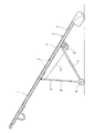
図1と図5に示すように、この発明に係るベルトコンベヤ21は、フレーム22の一方の端部側を接地させるコンベヤ本体23の下部途中の位置を両側一対の支持脚24で支持し、この支持脚24が、フレーム22の定位置に枢止された枢止側脚材25とフレーム22の長さ方向に可動となる可動側脚材26を接地側の下端で互いに結合して形成され、この両側支持脚24の開脚角度を、前記フレーム22に固定したウインチ27によるワイヤー28の巻取りまたは繰り出しで変えることにより、支持したコンベヤ本体23の傾斜角度を変化させることができるようになっている。
As shown in FIGS. 1 and 5, the
上記コンベヤ本体23は、後端側に設けたテールヘッド29のテール車輪30を接地させる長いフレーム22に多数のローラ31を並べて取付け、このローラ31群の外側にエンドレスのベルト32を巻回するとともに、テールヘッド29内に設けたモータ(図示省略)でベルト32を駆動するようになっている。
The
上記支持脚24は金属パイプ製であり、枢止側脚材25は、その上端をコンベヤ本体23の長さ方向の中間よりも後端側寄りの位置で、フレーム22を形成する溝形材33に固定した腕板34にピン35の結合によって取付け、可動側脚材26は、図2のように、上端に設けた腕板34の側面に枢止した鍔付きローラ35で、枢止側脚材25の枢止位置よりも前方で溝形材33の下面を支持し、上端が溝形材33の長さ方向に移動可能になっていると共に、枢止側脚材25と可動側脚材26はV字状となって開脚するよう、その下端を軸36で互いに枢止結合され、この結合軸36に接地用の車輪37が取付けられている。
The
両側の支持脚24の枢止側脚材25と可動側脚材26は、共に等しい長さを有し、枢止側脚材25同士が横桟38で、また、可動側脚材26同士が横桟39でそれぞれ結合され、図示のようなハンドル操作による手動式もしくは電動式のウインチ27から引き出したワイヤー28の先端は、可動側脚材26同士を結合する最上部横桟39に連結されている。
The
このウインチ27は、コンベヤ本体23のフレーム22における溝形材33間に固定した取付け座の下面に固定され、支持脚24の枢止側脚材25の上端枢止部の近傍位置に配置されている。
The
図2乃至図4のように、上記コンベヤ本体23のフレーム22を形成する両側溝形材33の内部に、この溝形材33の長さ方向に移動可能となり、溝形材33に対して任意の傾斜角度で、支持脚24の開脚方向に移動が生じないよう溝形材33の上下面に食い込むように作用するストッパー40が組み込まれ、前記可動側脚材26の上端に、この可動側脚材26の支持脚24の開脚方向への移動力で、前記ストッパー40を溝形材33の上下面に食い込むように押圧する当接片42が設けられている。
As shown in FIGS. 2 to 4, it is possible to move in the longitudinal direction of the
上記ストッパー40は、フレーム22の溝形材33における上下間隔に余裕を持って納まる幅と、溝形材33の上下面の間隔よりも長い長さを有する断面L字形となり、その両端を、溝形材33に対して上端が開脚方向の前方に位置する傾斜状態で溝形材33の上下面に当接して食い込む方向に作用する傾斜面40aとした平行四辺形に形成され、このストッパー40に、溝形材33の側面に対する固定用の押付けねじ43が取付けられている。
The
上記コンベヤ本体23のフレーム22を形成する溝形材33は、図2のように、一方の側面が上下に鍔壁33aを残して開放する角形の断面形状を有し、開放側面を外側にして両側に平行配置で結合することによりフレーム22を形成し、この溝形材33の内部に組み込んだストッパー40は、傾斜状態で上下の鍔壁33aによって外部に離脱しないようになっていると共に、傾斜状態にしたストッパー40に対して溝形材33の開放する側面から固定用の押付けねじ43をねじ込み、その先端を溝形材33の他方の側面に当接させると、ストッパー40は上下鍔壁33aの内面に押し当てられることで、溝形材33に対して固定化される。
As shown in FIG. 2, the
上記ストッパー40は、上記可動側脚材26の上端と連結部材41で溝形材33の長さ方向に一体動するように連結されている。この連結部材41としては図示のバネや強度のある線状物、可撓性の紐状物等を用い、図示の場合、可動側脚材26の上端に設けた腕板34の外面に突設したピン44と、ストッパー40の外面で中央よりも下寄りの位置に突設したピン45をバネで連結し、ストッパー40が可動側脚材26の上端と溝形材33の長さ方向に一体動するようにしている。
The
上記連結部材41は、ストッパー40の押付けねじ43と当接片42を連結し、上記したピン44と45を省くようにすることもできる。
The connecting
また、可動側脚材26の上端に設けた腕板34の内面で上部の位置に当接片42が突設してあり、この当接片42でストッパー40の下端部寄りの位置を開脚方向に押圧することで、傾斜状態にしたストッパー40の上下端部を溝形材33の上下面に食い込ませるようにし、ストッパー40を開脚側に移動しないように固定することで、支持脚24がコンベヤ本体23の荷重を支持するようにしている。
Further, a
この発明のベルトコンベヤ21は、上記のような構成であり、V字状に開脚させた支持脚24の車輪37とテールヘッド29のテール車輪30を接地させることにより、コンベヤ本体23を任意の傾斜角度で支持し、コンベヤ本体23の上部排出端を荷揚げ位置に臨ませた状態でベルト32を駆動し、テールヘッド側から供給した搬送物を荷揚げ位置に搬送するものである。
The
上記ベルトコンベヤ21において、図2(a)と(b)のように、ストッパー40は溝形材33の長さ方向に対して上端が搬送方向の前方に位置する傾斜状態で、押付けねじ43をねじ込んで溝形材33に固定され、開脚する支持脚24の可動側脚材26の上端に設けた当接片42が前記ストッパー40に当接し、このストッパー40の下部を開脚方向に押圧することで、図4(a)の矢印のように、押圧力がストッパー40の上下端部が溝形材33の上下面に食い込むように作用し、これによって、ストッパー40は可動側脚材26の上端を開脚側に移動しないように固定することになり、支持脚24のV字状開脚角度を固定化し、支持脚24は自身で荷重を支持することで、可動側脚材26の上端部に連結したワイヤー28を介してウインチ27に大きな負荷をかけないようにする。
In the
上記ベルトコンベヤ21において、コンベヤ本体23の傾斜角度を荷揚げ位置の高さ条件に合わせて変更するには、図5(b)のように、支持脚24の可動側脚材26を閉脚方向に移動させて上部排出端を高くする場合と、図5(a)のように、支持脚24の可動側脚材26を開脚方向に移動させて上部排出端を低くする場合がある。
In the
前者の上部排出端を高くする場合は、ストッパー40の押付けねじ43を緩めた状態で、ウインチ27を操作してワイヤー28を巻き取るようにすると、可動側脚材26の上端が引かれて枢止側脚材25に接近し、支持脚24は開脚角度が狭くなることでコンベヤ本体23を押し上げることになる。
In the case of increasing the former upper discharge end, if the
このとき、可動側脚材26の上端に連結部材41を介して連結したストッパー40は、溝形材33の長さ方向に沿わせ、その下端側が支持脚24の閉脚方向に引かれることで、溝形材33の上下面に食い込まないようになり、従って、可動側脚材26の上端とストッパー40は、閉脚方向へ支障なく移動し、コンベヤ本体23の上部排出端が所定高さになると、ウインチ27によるワイヤー28の巻き取りを止める。
At this time, the
上記ストッパー40は、移動後の位置で押付けねじ43をねじ込んで溝形材33に固定化し、可動側脚材26の上端に設けた当接片42をストッパー40の下部に当接させると、可動側脚材26の開脚方向の力が当接片42を介してストッパー40に加わり、当接片42の押圧力がこのストッパー40の上下端部を溝形材33の上下面に食い込ませるように作用し、可動側脚材26の上端が溝形材33に対して開脚方向に固定化するので、調整後の支持脚24の開脚角度を保持することになる。
The
また、後者の上部排出端を低くする場合は、先ず、図4(b)のように、ストッパー40の押付けねじ43を緩めた状態で、ストッパー40を溝形材33の長さ方向に沿うよう倒し、次に、ウインチ27を操作してワイヤー28を繰り出すようにすると、V字状に開脚する支持脚24に加わる荷重の開脚作用で、可動側脚材26の上端は開脚方向に移動し、支持脚24の開脚角度が広がることでコンベヤ本体23の上部排出端が下降して所定高さになると、ウインチ27によるワイヤー28の繰り出しを止める。
In order to lower the upper discharge end of the latter, first, as shown in FIG. 4 (b), with the
この状態で、ストッパー40を、溝形材33の長さ方向に対して傾斜させ、その下端部寄りの位置を当接片42に当接させて押付けねじ43をねじ込み、図4(a)の状態に戻せば、可動側脚材26の開脚方向の力が当接片42を介してストッパー40に加わり、このストッパー40は上下端部が溝形材33の上下面に食い込むように作用し、可動側脚材26の上端が開脚方向に対して固定化するので、調整後の支持脚24の開脚角度を保持することになる。
In this state, the
このように、コンベヤ本体23の開脚角度の調整後は、可動側脚材26の上端がストッパー40を介して溝形材33に開脚方向へ移動しないよう固定化されるので、支持脚24自身でコンベヤ本体23と搬送物の重量や搬送物の荷下し時の衝撃を支持することができ、ワイヤー28を介して支持脚24の開脚や閉脚を操作するウインチ27に大きな負荷がかからないので、使用するウインチ27の小型、小能力化を実現することができる。
Thus, after adjusting the leg opening angle of the
21 ベルトコンベヤ
22 フレーム
23 コンベヤ本体
24 支持脚
25 枢止側脚材
26 可動側脚材
27 ウインチ
28 ワイヤー
29 テールヘッド
30 テール車輪
31 多数のローラ
32 ベルト
33 溝形材
34 腕板
35 ピン
36 軸
37 車輪
38 横桟
39 横桟
40 ストッパー
41 連結部材
42 当接片
43 押付けねじ
44 ピン
45 ピン
21
Claims (3)
前記コンベヤ本体のフレームを形成する両側溝形材の内部に、この溝形材の長さ方向に移動可能となり、溝形材に対して任意の傾斜角度で、支持脚の開脚方向に移動が生じないよう溝形材の上下面に食い込むように作用するストッパーを組み込み、前記可動側脚材の上端に、この可動側脚材の支持脚開脚方向への移動力で、前記ストッパーを溝形材の上下面に食い込むように押圧する当接片を設けたことを特徴とするベルトコンベヤ。 The lower half of the conveyor body, where one end of the frame is grounded, is supported by a pair of supporting legs on both sides. Conveyor body that is formed by joining movable legs together at the lower end on the grounding side, and changing the open leg angle of the support legs on both sides by winding or unwinding the wire with a winch fixed to the frame In the belt conveyor that can change the inclination angle of
It is possible to move in the length direction of the groove shape material inside the both side groove shape material forming the frame of the conveyor body, and it can move in the opening direction of the support leg at an arbitrary inclination angle with respect to the groove shape material. A stopper that works to bite into the upper and lower surfaces of the grooved material is incorporated so that it does not occur. A belt conveyor comprising a contact piece that presses against the upper and lower surfaces of a material.
Priority Applications (1)
| Application Number | Priority Date | Filing Date | Title |
|---|---|---|---|
| JP2008228244A JP5316933B2 (en) | 2008-09-05 | 2008-09-05 | Belt conveyor |
Applications Claiming Priority (1)
| Application Number | Priority Date | Filing Date | Title |
|---|---|---|---|
| JP2008228244A JP5316933B2 (en) | 2008-09-05 | 2008-09-05 | Belt conveyor |
Publications (2)
| Publication Number | Publication Date |
|---|---|
| JP2010058938A true JP2010058938A (en) | 2010-03-18 |
| JP5316933B2 JP5316933B2 (en) | 2013-10-16 |
Family
ID=42186217
Family Applications (1)
| Application Number | Title | Priority Date | Filing Date |
|---|---|---|---|
| JP2008228244A Active JP5316933B2 (en) | 2008-09-05 | 2008-09-05 | Belt conveyor |
Country Status (1)
| Country | Link |
|---|---|
| JP (1) | JP5316933B2 (en) |
Cited By (2)
| Publication number | Priority date | Publication date | Assignee | Title |
|---|---|---|---|---|
| KR101101423B1 (en) * | 2011-07-20 | 2012-01-02 | 현대콘베어주식회사 | Conveyor apparatus |
| CN108249107A (en) * | 2018-03-22 | 2018-07-06 | 上海晟哲机械科技有限公司 | A kind of automation climbing conveyer |
Citations (3)
| Publication number | Priority date | Publication date | Assignee | Title |
|---|---|---|---|---|
| JPS4856785U (en) * | 1971-10-30 | 1973-07-20 | ||
| JPS5426283U (en) * | 1977-07-26 | 1979-02-21 | ||
| JPS55136708U (en) * | 1979-03-22 | 1980-09-29 |
-
2008
- 2008-09-05 JP JP2008228244A patent/JP5316933B2/en active Active
Patent Citations (3)
| Publication number | Priority date | Publication date | Assignee | Title |
|---|---|---|---|---|
| JPS4856785U (en) * | 1971-10-30 | 1973-07-20 | ||
| JPS5426283U (en) * | 1977-07-26 | 1979-02-21 | ||
| JPS55136708U (en) * | 1979-03-22 | 1980-09-29 |
Cited By (2)
| Publication number | Priority date | Publication date | Assignee | Title |
|---|---|---|---|---|
| KR101101423B1 (en) * | 2011-07-20 | 2012-01-02 | 현대콘베어주식회사 | Conveyor apparatus |
| CN108249107A (en) * | 2018-03-22 | 2018-07-06 | 上海晟哲机械科技有限公司 | A kind of automation climbing conveyer |
Also Published As
| Publication number | Publication date |
|---|---|
| JP5316933B2 (en) | 2013-10-16 |
Similar Documents
| Publication | Publication Date | Title |
|---|---|---|
| US7128201B2 (en) | Conveyor conversion kit for replacing rollers within conveyor system and method | |
| JP5859989B2 (en) | Conveyor | |
| CN109715532A (en) | Charging and discharge component for conveyer | |
| CA2759605C (en) | Conveyor for the transport of bulk materials | |
| US9221651B2 (en) | Swinging sheave bracket with force control | |
| US20190024426A1 (en) | Opening and closing mechanism for opening and closing bodies | |
| JPH09104516A (en) | Conveyor belt assembly | |
| JP2010058938A (en) | Conveyor belt | |
| US20070267273A1 (en) | Foldable conveyor with automatic tensioning device | |
| JPH0747406B2 (en) | Conveyor belt synchronous tension device | |
| KR200401152Y1 (en) | Elevated-up/down type carrier according to the weight | |
| CN218231067U (en) | Logistics turnover conveying device | |
| CN111003571A (en) | Self-supporting formula pad pasting mechanism | |
| CN106956897B (en) | Multisection cantilever type telescopic machine | |
| JP2010150840A (en) | Rolling screen | |
| EP1093949A2 (en) | Canvas cover for trucks | |
| CN212023836U (en) | Belt feeder overspeed device tensioner | |
| KR20090056734A (en) | Discharge guide for press | |
| JP4589145B2 (en) | Combine waste transport device | |
| JP5250274B2 (en) | Moving shelf and its safety mechanism | |
| CN214568451U (en) | Novel belt conveyor middle tensioning device | |
| KR20000014672U (en) | Tension weight stop device of belt conveyor | |
| US890021A (en) | Portable grain-elevator. | |
| JPH1067416A (en) | Skirt device for belt conveyor | |
| CN219669225U (en) | Chain tensioning device |
Legal Events
| Date | Code | Title | Description |
|---|---|---|---|
| A621 | Written request for application examination |
Free format text: JAPANESE INTERMEDIATE CODE: A621 Effective date: 20110518 |
|
| A977 | Report on retrieval |
Free format text: JAPANESE INTERMEDIATE CODE: A971007 Effective date: 20130314 |
|
| A131 | Notification of reasons for refusal |
Free format text: JAPANESE INTERMEDIATE CODE: A131 Effective date: 20130402 |
|
| A521 | Request for written amendment filed |
Free format text: JAPANESE INTERMEDIATE CODE: A523 Effective date: 20130521 |
|
| TRDD | Decision of grant or rejection written | ||
| A01 | Written decision to grant a patent or to grant a registration (utility model) |
Free format text: JAPANESE INTERMEDIATE CODE: A01 Effective date: 20130611 |
|
| A61 | First payment of annual fees (during grant procedure) |
Free format text: JAPANESE INTERMEDIATE CODE: A61 Effective date: 20130627 |
|
| R150 | Certificate of patent or registration of utility model |
Ref document number: 5316933 Country of ref document: JP Free format text: JAPANESE INTERMEDIATE CODE: R150 Free format text: JAPANESE INTERMEDIATE CODE: R150 |
|
| R250 | Receipt of annual fees |
Free format text: JAPANESE INTERMEDIATE CODE: R250 |
|
| R250 | Receipt of annual fees |
Free format text: JAPANESE INTERMEDIATE CODE: R250 |
|
| R250 | Receipt of annual fees |
Free format text: JAPANESE INTERMEDIATE CODE: R250 |
|
| R250 | Receipt of annual fees |
Free format text: JAPANESE INTERMEDIATE CODE: R250 |
|
| R250 | Receipt of annual fees |
Free format text: JAPANESE INTERMEDIATE CODE: R250 |
|
| R250 | Receipt of annual fees |
Free format text: JAPANESE INTERMEDIATE CODE: R250 |
|
| R250 | Receipt of annual fees |
Free format text: JAPANESE INTERMEDIATE CODE: R250 |
|
| R250 | Receipt of annual fees |
Free format text: JAPANESE INTERMEDIATE CODE: R250 |