JP2010054523A - Imaging lens - Google Patents
Imaging lens Download PDFInfo
- Publication number
- JP2010054523A JP2010054523A JP2007124819A JP2007124819A JP2010054523A JP 2010054523 A JP2010054523 A JP 2010054523A JP 2007124819 A JP2007124819 A JP 2007124819A JP 2007124819 A JP2007124819 A JP 2007124819A JP 2010054523 A JP2010054523 A JP 2010054523A
- Authority
- JP
- Japan
- Prior art keywords
- lens
- sub
- image side
- object side
- imaging
- Prior art date
- Legal status (The legal status is an assumption and is not a legal conclusion. Google has not performed a legal analysis and makes no representation as to the accuracy of the status listed.)
- Granted
Links
Images


Classifications
-
- G—PHYSICS
- G02—OPTICS
- G02B—OPTICAL ELEMENTS, SYSTEMS OR APPARATUS
- G02B13/00—Optical objectives specially designed for the purposes specified below
- G02B13/001—Miniaturised objectives for electronic devices, e.g. portable telephones, webcams, PDAs, small digital cameras
- G02B13/0055—Miniaturised objectives for electronic devices, e.g. portable telephones, webcams, PDAs, small digital cameras employing a special optical element
- G02B13/006—Miniaturised objectives for electronic devices, e.g. portable telephones, webcams, PDAs, small digital cameras employing a special optical element at least one element being a compound optical element, e.g. cemented elements
-
- G—PHYSICS
- G02—OPTICS
- G02B—OPTICAL ELEMENTS, SYSTEMS OR APPARATUS
- G02B1/00—Optical elements characterised by the material of which they are made; Optical coatings for optical elements
-
- G—PHYSICS
- G02—OPTICS
- G02B—OPTICAL ELEMENTS, SYSTEMS OR APPARATUS
- G02B1/00—Optical elements characterised by the material of which they are made; Optical coatings for optical elements
- G02B1/04—Optical elements characterised by the material of which they are made; Optical coatings for optical elements made of organic materials, e.g. plastics
- G02B1/041—Lenses
-
- G—PHYSICS
- G02—OPTICS
- G02B—OPTICAL ELEMENTS, SYSTEMS OR APPARATUS
- G02B13/00—Optical objectives specially designed for the purposes specified below
- G02B13/001—Miniaturised objectives for electronic devices, e.g. portable telephones, webcams, PDAs, small digital cameras
- G02B13/0015—Miniaturised objectives for electronic devices, e.g. portable telephones, webcams, PDAs, small digital cameras characterised by the lens design
- G02B13/002—Miniaturised objectives for electronic devices, e.g. portable telephones, webcams, PDAs, small digital cameras characterised by the lens design having at least one aspherical surface
- G02B13/0035—Miniaturised objectives for electronic devices, e.g. portable telephones, webcams, PDAs, small digital cameras characterised by the lens design having at least one aspherical surface having three lenses
-
- G—PHYSICS
- G02—OPTICS
- G02B—OPTICAL ELEMENTS, SYSTEMS OR APPARATUS
- G02B7/00—Mountings, adjusting means, or light-tight connections, for optical elements
- G02B7/008—Mountings, adjusting means, or light-tight connections, for optical elements with means for compensating for changes in temperature or for controlling the temperature; thermal stabilisation
-
- G—PHYSICS
- G02—OPTICS
- G02B—OPTICAL ELEMENTS, SYSTEMS OR APPARATUS
- G02B9/00—Optical objectives characterised both by the number of the components and their arrangements according to their sign, i.e. + or -
- G02B9/12—Optical objectives characterised both by the number of the components and their arrangements according to their sign, i.e. + or - having three components only
- G02B9/14—Optical objectives characterised both by the number of the components and their arrangements according to their sign, i.e. + or - having three components only arranged + - +
- G02B9/24—Optical objectives characterised both by the number of the components and their arrangements according to their sign, i.e. + or - having three components only arranged + - + two of the components having compound lenses
- G02B9/28—Optical objectives characterised both by the number of the components and their arrangements according to their sign, i.e. + or - having three components only arranged + - + two of the components having compound lenses the middle and rear components having compound lenses
Abstract
Description
この発明は、撮像レンズ、特に携帯電話器等に搭載して好適な撮像レンズに関する。 The present invention relates to an imaging lens, and particularly to an imaging lens suitable for being mounted on a mobile phone or the like.
デジタルカメラを内蔵する携帯電話器には、撮像レンズがプリント配線基板に実装されている。プリント配線基板に撮像レンズを実装する手法として、リフローはんだ付け(Reflow soldering)処理が採用されている。以後、リフローはんだ付け処理を、単に「リフロー処理」ということもある。リフロー処理とは、プリント配線基板上で電子部品を接続する個所にあらかじめハンダボールを配置し、そこに電子部品を配置してから加熱して、ハンダボールを溶融させた後冷却することによって、電子部品をハンダ付けする手法のことを言う。 An imaging lens is mounted on a printed wiring board in a mobile phone incorporating a digital camera. As a method for mounting an imaging lens on a printed wiring board, a reflow soldering process is employed. Hereinafter, the reflow soldering process may be simply referred to as “reflow process”. The reflow process is to place solder balls in advance on the printed circuit board where electronic components are connected, place the electronic components there, heat them, melt the solder balls, and then cool them down. This is a method of soldering parts.
大量生産工程において、一般に、プリント配線基板に電子素子あるいは撮像レンズ等の部品類を実装する手法として、リフロー処理を実施するリフロー工程が採用される。リフロー工程によれば、部品類のプリント配線基板への実装コストが安くすみ、かつ製造品質を一定に保つことができる。 In a mass production process, a reflow process for performing a reflow process is generally employed as a technique for mounting electronic elements or components such as an imaging lens on a printed wiring board. According to the reflow process, the mounting cost of components on the printed wiring board can be reduced, and the manufacturing quality can be kept constant.
撮像レンズを具える携帯電話器の製造工程におけるリフロー工程においては、電子部品が、プリント配線基板の所定位置に配置されることはもちろん、撮像レンズそのもの、あるいは撮像レンズを取り付けるためのソケット等がプリント配線基板に配置される。 In the reflow process in the manufacturing process of a mobile phone equipped with an imaging lens, electronic components are placed at predetermined positions on the printed circuit board, and the imaging lens itself or a socket for mounting the imaging lens is printed. Arranged on the wiring board.
携帯電話器に取り付けられる撮像レンズは、製造コストの低減及びレンズ性能の確保のために、そのほとんどがプラスチックを素材として作製されている。このため、リフロー工程において、撮像レンズが高温環境におかれることによって熱変形し、その光学的性能を維持できなくなることを防止するため、撮像レンズを装填するための耐熱性ソケット部品を利用する工夫がなされている。 Most imaging lenses attached to a mobile phone are made of plastic as a material in order to reduce manufacturing costs and secure lens performance. For this reason, in the reflow process, in order to prevent the imaging lens from being thermally deformed by being placed in a high temperature environment and maintaining its optical performance, a device using a heat-resistant socket part for mounting the imaging lens is used. Has been made.
すなわち、リフロー工程においては、撮像レンズを装填するための耐熱性ソケット部品を携帯電話器のプリント配線基板に取り付け、リフロー工程終了後に、撮像レンズをこのソケットに取り付けることによって、撮像レンズがリフロー工程で高温にさらされることを防ぐ方策が採られている(例えば、特許文献1〜3参照)。しかしながら、撮像レンズを装填するために耐熱性ソケット部品を利用することは、製造工程を複雑にし、この耐熱性ソケットのコスト等を含めて、製造コストが高くなるという問題がある。
In other words, in the reflow process, a heat-resistant socket part for mounting the imaging lens is attached to the printed wiring board of the mobile phone, and after the reflow process is completed, the imaging lens is attached to the socket. Measures have been taken to prevent exposure to high temperatures (see, for example,
また、最近は、携帯電話器が、一時的に高温環境となる乗用車の車内等に放置されることも考慮して、携帯電話器そのものが、150℃程度の高温環境に置かれた場合であっても、この携帯電話器に装填されている撮像レンズには、その光学的性能が劣化しないことが要請されている。従来の、プラスチック素材で形成された撮像レンズでは、この要請に完全には応えられない。 Recently, the mobile phone itself has been placed in a high-temperature environment of about 150 ° C, taking into consideration that the mobile phone is left in a passenger car or the like that is temporarily in a high-temperature environment. However, it is required that the optical performance of the imaging lens mounted in the mobile phone is not deteriorated. Conventional imaging lenses made of plastic material cannot fully meet this requirement.
高温環境でも光学的性能が維持される撮像レンズを実現するために、撮像レンズを高軟化温度のモールドガラス素材を利用して形成することが考えられる(例えば、特許文献4参照)。高軟化温度のモールドガラス素材が軟化する温度は数百度以上であるので、高温の環境によって撮像レンズの光学的性能が劣化するという問題は回避できるが、現時点では、モールドガラス素材を利用して構成される撮像レンズは、その製造コストが非常に高く、あまり普及していない。 In order to realize an imaging lens whose optical performance is maintained even in a high temperature environment, it is conceivable to form the imaging lens using a mold glass material having a high softening temperature (see, for example, Patent Document 4). Since the softening temperature of the mold glass material with a high softening temperature is several hundred degrees or more, it is possible to avoid the problem that the optical performance of the imaging lens deteriorates due to the high temperature environment, but at present, it is configured using the mold glass material. The imaging lens to be manufactured has a very high manufacturing cost and is not so popular.
携帯電話器等に装填される撮像レンズは、上述の熱的特性に加えて光学的な特性についても、次のような条件を満たす必要がある。すなわち、光学長(optical length)が短い必要がある。光学長とは、撮像レンズの物体側の入射面から結像面(撮像面ということもある。)までの長さである。言い換えると、レンズの設計において、撮像レンズの合成焦点距離に対する光学長の比を小さくする工夫が必要である。携帯電話器を例にとると、少なくともこの光学長は、携帯電話器本体の厚みより短くなければならない。 An imaging lens loaded in a cellular phone or the like needs to satisfy the following conditions regarding optical characteristics in addition to the above-described thermal characteristics. That is, the optical length needs to be short. The optical length is the length from the object-side incident surface of the imaging lens to the imaging surface (sometimes referred to as an imaging surface). In other words, in designing the lens, it is necessary to devise a method for reducing the ratio of the optical length to the combined focal length of the imaging lens. Taking a cellular phone as an example, at least this optical length must be shorter than the thickness of the cellular phone body.
一方、撮像レンズの像側の出射面から撮像面までの距離として定義されるバックフォーカスは、可能な限り長いのが好都合である。すなわち、レンズの設計において、焦点距離に対するバックフォーカスの比はできるだけ大きくする工夫が必要である。これは、撮像レンズと撮像面との間にフィルタやカバーガラス等の部品を挿入する必要があるためである。 On the other hand, the back focus, which is defined as the distance from the exit surface on the image side of the imaging lens to the imaging surface, is advantageously as long as possible. In other words, in designing the lens, it is necessary to devise a ratio of the back focus to the focal length as large as possible. This is because it is necessary to insert components such as a filter and a cover glass between the imaging lens and the imaging surface.
上述した以外にも、撮像レンズとして、諸収差が、像の歪みが視覚を通じて意識されず、かつCCDイメージセンサ(charge coupled device image sensor)等の受光面にマトリックス状に並んでいる光を検知する最小単位の素子(「画素」とも呼ばれる。)の集積密度から要請される十分な程度に小さく補正されていることが当然に要請される。すなわち、撮像レンズは、諸収差が良好に補正されている必要がある。以下、このように諸収差が良好に補正された画像を「良好な画像」ということもある。
そこで、この発明の目的は、携帯電話器等に搭載して好適な撮像レンズであって、リフロー工程においても、また、携帯電話器等に装填されて一時的に設計仕様における最高の温度環境に置かれた場合であっても、光学的性能が劣化しないという耐熱性が保証された撮像レンズを提供することにある。 Accordingly, an object of the present invention is an imaging lens suitable for being mounted on a mobile phone or the like, and is mounted on the mobile phone or the like temporarily in the reflow process or temporarily in the highest temperature environment in the design specification. An object of the present invention is to provide an imaging lens in which heat resistance is ensured such that optical performance does not deteriorate even when placed.
また、携帯電話器等に搭載可能な程度に光学長が短く、バックフォーカスは撮像レンズと撮像面との間にフィルタやカバーガラス等の部品を挿入可能な程度に長く、かつ良好な画像が得られる撮像レンズを提供することにある。 In addition, the optical length is short enough to be mounted on a mobile phone, etc., and the back focus is long enough to allow parts such as a filter and cover glass to be inserted between the imaging lens and the imaging surface, and a good image can be obtained. An imaging lens is provided.
上述の目的を達成するため、この発明の第1形態の撮像レンズは、以下のとおり構成される。すなわち、この発明の第1形態の撮像レンズは、第1レンズと、第2レンズと、第3レンズとを具えている。第1レンズ、第2レンズ、及び第3レンズのうち一つのレンズが、硬化性樹脂材料又は高軟化温度の光学レンズの形成用材料で形成される単レンズであることが特徴である。残りの二つのレンズは、それぞれ第1サブレンズ、第2サブレンズ、及び第3サブレンズの3枚のサブレンズをこの順に接着した状態にある接合型複合レンズである。これら二つの接合型複合レンズのそれぞれは、第1サブレンズ及び第3サブレンズが、硬化性樹脂材料で形成され、第2サブレンズが、高軟化温度の光学レンズの形成用材料で形成される。 In order to achieve the above object, the imaging lens of the first embodiment of the present invention is configured as follows. That is, the imaging lens according to the first aspect of the present invention includes a first lens, a second lens, and a third lens. One of the first lens, the second lens, and the third lens is a single lens formed of a curable resin material or a material for forming an optical lens having a high softening temperature. The remaining two lenses are cemented compound lenses in which the three sub lenses of the first sub lens, the second sub lens, and the third sub lens are bonded in this order. In each of these two junction type compound lenses, the first sub lens and the third sub lens are formed of a curable resin material, and the second sub lens is formed of a material for forming an optical lens having a high softening temperature. .
この発明の第2形態の撮像レンズは、以下のとおり構成される。すなわち、この発明の第2形態の撮像レンズは、第1レンズと、第2レンズと、第3レンズとを具えている。第1レンズ、第2レンズ、及び第3レンズのうち二つのレンズが、硬化性樹脂材料又は高軟化温度の光学レンズの形成用材料で形成される単レンズであることが特徴である。残りの一つのレンズは、第1サブレンズ、第2サブレンズ、及び第3サブレンズの3枚のサブレンズをこの順に接着した状態にある接合型複合レンズである。この接合型複合レンズは、第1サブレンズ及び第3サブレンズが、硬化性樹脂材料で形成され、第2サブレンズが、高軟化温度の光学レンズの形成用材料で形成される。 The imaging lens of the second embodiment of the present invention is configured as follows. That is, the imaging lens according to the second aspect of the present invention includes a first lens, a second lens, and a third lens. Two of the first lens, the second lens, and the third lens are single lenses formed of a curable resin material or a material for forming an optical lens having a high softening temperature. The remaining one lens is a cemented compound lens in which the three sub lenses of the first sub lens, the second sub lens, and the third sub lens are bonded in this order. In this junction type compound lens, the first sub lens and the third sub lens are formed of a curable resin material, and the second sub lens is formed of a material for forming an optical lens having a high softening temperature.
ここで、硬化性樹脂(Curable Resin)材料とは、熱硬化性樹脂(Thermosetting resin)材料及び紫外線硬化樹脂(UV-Curable Resin)材料のいずれをも指す。また、高軟化温度の光学レンズの形成用材料とは、高軟化温度のモールドガラス素材、あるいは、後述するBK7等の光学ガラス等を指す。 Here, the curable resin material refers to both a thermosetting resin material and an ultraviolet-curable resin material. The material for forming an optical lens having a high softening temperature refers to a mold glass material having a high softening temperature, or an optical glass such as BK7 described later.
光学ガラスで形成される第2サブレンズと、硬化性樹脂材料で形成される第1サブレンズ又は第3サブレンズとの接着は次のように実現される。光学ガラスで形成される第2サブレンズに、液体状の硬化性樹脂を接触させて、この硬化性樹脂を固体化、すなわち硬化させることによって、第1サブレンズ又は第3サブレンズが第2サブレンズに接着される。この接着を、以後、直接接着ということもある。また、第2サブレンズと、第1サブレンズ又は第3サブレンズとのとの間に接着剤を介在させて第2サブレンズと、第1サブレンズ又は第3サブレンズとの接着を実現させても良い。この接着を、以後、間接接着ということもある。 Adhesion between the second sub-lens formed of the optical glass and the first sub-lens or the third sub-lens formed of the curable resin material is realized as follows. By bringing a liquid curable resin into contact with the second sub-lens formed of optical glass and solidifying the curable resin, that is, curing the first sub-lens or the third sub-lens to the second sub-lens. Bonded to the lens. Hereinafter, this adhesion may be referred to as direct adhesion. In addition, an adhesive is interposed between the second sub lens and the first sub lens or the third sub lens to realize adhesion between the second sub lens and the first sub lens or the third sub lens. May be. Hereinafter, this adhesion may be referred to as indirect adhesion.
間接接着を実現する場合、光学ガラスの屈折率と、硬化性樹脂材料の屈折率に関して、接着剤の屈折率を適宜選択する等、接着剤の光学的特性を積極的に利用する意図を持って接着剤を選択すれば、第2サブレンズと、第1サブレンズ又は第3サブレンズとの界面における反射を低減する等の効果を得ることも可能である。また、接着剤を介在させるか否かにかかわらず、第2サブレンズの、第1サブレンズ又は第3サブレンズに対向する面に、コーティング処理を施した上で、両者を接着すれば、第1サブレンズ(又は第3サブレンズ)との界面における反射を低減する等の効果を得ることも可能である。 In the case of realizing indirect bonding, with the intention to actively use the optical properties of the adhesive, such as appropriately selecting the refractive index of the adhesive with respect to the refractive index of the optical glass and the refractive index of the curable resin material. If an adhesive is selected, it is possible to obtain an effect of reducing reflection at the interface between the second sub lens and the first sub lens or the third sub lens. Regardless of whether or not an adhesive is interposed, the surface of the second sub-lens facing the first sub-lens or the third sub-lens is coated and then bonded to It is also possible to obtain an effect of reducing reflection at the interface with the first sub lens (or the third sub lens).
すなわち、ここでいうサブレンズ同士の接着とは、上述したように、接着剤を介在させることなくサブレンズ同士を接着する直接接着を含むことはもちろん、サブレンズ間に接着剤を介在させて実現される間接接着も含むものとする。 That is, the term “adhesion between sub-lenses” here includes, as described above, the direct adhesion of adhering the sub-lenses without interposing an adhesive, as well as the inter-lens interposing an adhesive. Indirect bonding is also included.
この発明の撮像レンズは、より具体的には、第1〜第6の撮像レンズとして構成される。 More specifically, the imaging lens of the present invention is configured as first to sixth imaging lenses.
第1の撮像レンズは、第1レンズと、開口絞りと、第2レンズと、第3レンズとを具え、物体側から像側に向って、第1レンズ、開口絞り、第2レンズ、第3レンズの順に配列されて構成される。 The first imaging lens includes a first lens, an aperture stop, a second lens, and a third lens. From the object side to the image side, the first lens, the aperture stop, the second lens, and the third lens Arranged in the order of lenses.
第1レンズは、近軸上で物体側に凸面を向けたメニスカス形状の単レンズである。第2レンズは、物体側から像側に向って、第1サブレンズ、第2サブレンズ及び第3サブレンズの順に配列され、第1サブレンズと第2サブレンズとが接着され、かつ第2サブレンズと第3サブレンズとが接着された状態の接合型複合レンズである。第3レンズは、物体側から像側に向って、第4サブレンズ、第5サブレンズ及び第6サブレンズの順に配列され、第4サブレンズと第5サブレンズとが接着され、かつ第5サブレンズと第6サブレンズとが接着された状態の接合型複合レンズである。 The first lens is a meniscus single lens having a convex surface facing the object side on the paraxial axis. The second lens is arranged in the order of the first sub lens, the second sub lens, and the third sub lens from the object side to the image side, the first sub lens and the second sub lens are bonded, and the second sub lens This is a cemented compound lens in which the sub lens and the third sub lens are bonded. The third lens is arranged in the order of the fourth sub lens, the fifth sub lens, and the sixth sub lens from the object side to the image side, the fourth sub lens and the fifth sub lens are bonded, and the fifth sub lens This is a junction type compound lens in which the sub lens and the sixth sub lens are bonded.
第1レンズは、硬化性樹脂材料又は高軟化温度の光学レンズの形成用材料で形成され、第1サブレンズ、第3サブレンズ、第4サブレンズ、及び第6サブレンズは硬化性樹脂材料で形成され、第2サブレンズ、及び第5サブレンズは、高軟化温度の光学レンズの形成用材料で形成される。 The first lens is made of a curable resin material or a material for forming an optical lens having a high softening temperature, and the first sub lens, the third sub lens, the fourth sub lens, and the sixth sub lens are made of a curable resin material. The second sub lens and the fifth sub lens are formed of a material for forming an optical lens having a high softening temperature.
そして、第1の撮像レンズは、以下の条件(1-1)〜(1-8)を満たす。 The first imaging lens satisfies the following conditions (1-1) to (1-8).
0≦|N5-N4|≦0.1 (1-1)
0≦|N5-N6|≦0.1 (1-2)
0≦|ν5-ν4|≦30.0 (1-3)
0≦|ν5-ν6|≦30.0 (1-4)
0≦|N9-N8|≦0.1 (1-5)
0≦|N9-N10|≦0.1 (1-6)
0≦|ν9-ν8|≦30.0 (1-7)
0≦|ν9-ν10|≦30.0 (1-8)
ただし、
N4:前記第1サブレンズの屈折率
N5:前記第2サブレンズの屈折率
N6:前記第3サブレンズの屈折率
ν4:前記第1サブレンズのアッベ数
ν5:前記第2サブレンズのアッベ数
ν6:前記第3サブレンズのアッベ数
N8:前記第4サブレンズの屈折率
N9:前記第5サブレンズの屈折率
N10:前記第6サブレンズの屈折率
ν8:前記第4サブレンズのアッベ数
ν9:前記第5サブレンズのアッベ数
ν10:前記第6サブレンズのアッベ数
である。
0 ≦ | N 5 -N 4 | ≦ 0.1 (1-1)
0 ≦ | N 5 -N 6 | ≦ 0.1 (1-2)
0 ≦ | ν 5 -ν 4 | ≦ 30.0 (1-3)
0 ≦ | ν 5 -ν 6 | ≦ 30.0 (1-4)
0 ≦ | N 9 -N 8 | ≦ 0.1 (1-5)
0 ≦ | N 9 -N 10 | ≦ 0.1 (1-6)
0 ≦ | ν 9 -ν 8 | ≦ 30.0 (1-7)
0 ≦ | ν 9 -ν 10 | ≦ 30.0 (1-8)
However,
N 4 : refractive index of the first sub-lens
N 5 : refractive index of the second sub-lens
N 6 : Refractive index of the third sub lens ν 4 : Abbe number of the first sub lens ν 5 : Abbe number of the second sub lens ν 6 : Abbe number of the third sub lens
N 8 : refractive index of the fourth sub-lens
N 9 : refractive index of the fifth sub-lens
N 10 : refractive index of the sixth sub lens ν 8 : Abbe number of the fourth sub lens ν 9 : Abbe number of the fifth sub lens ν 10 : Abbe number of the sixth sub lens
更に、第1の撮像レンズは、次のように構成するのが好適である。すなわち、第1の撮像レンズの構成要素である、第2レンズ及び第3レンズをそれぞれ構成する第1〜第3サブレンズ、及び第4〜第6サブレンズを以下のとおりとするのが好適である。 Further, the first imaging lens is preferably configured as follows. That is, it is preferable that the first to third sub lenses and the fourth to sixth sub lenses constituting the second lens and the third lens, which are components of the first imaging lens, are as follows. is there.
第2レンズを構成するサブレンズのうち、第2サブレンズを、平行平面ガラス板とし、第1サブレンズを、近軸上で当該第1サブレンズの物体側面が物体側に凹面を向けた平凹レンズ(planoconcave lens)とし、第3サブレンズを、近軸上で当該第3サブレンズの像側面が像側に凸面を向けた平凸レンズ(planoconvex lens)とする。平行平面ガラス板は、オプティカルパラレルガラス板(Optical-parallel glass plate)と呼ばれることもある。平行平面ガラス板は、レンズとは一般には呼ばれないが、ここでは説明の便宜上、レンズ面の曲率半径が無限大である特別な場合として平行平面ガラス板を含めてレンズと称することもある。 Of the sub lenses constituting the second lens, the second sub lens is a plane parallel glass plate, and the first sub lens is a flat surface in which the object side surface of the first sub lens is a concave surface facing the object side on a paraxial line. A concave lens (planoconcave lens) is used, and the third sub lens is a planoconvex lens in which the image side surface of the third sub lens is a convex surface facing the image side on the paraxial side. The parallel flat glass plate is sometimes called an optical-parallel glass plate. The plane-parallel glass plate is not generally called a lens, but for convenience of explanation, the plane-parallel glass plate is sometimes referred to as a lens including the plane-parallel glass plate as a special case where the radius of curvature of the lens surface is infinite.
また、第3レンズを構成するサブレンズのうち、第5サブレンズを、平行平面ガラス板とし、第4サブレンズを、近軸上で当該第4サブレンズの物体側面が物体側に凸面を向けた平凸レンズとし、第6サブレンズを、近軸上で当該第6サブレンズの像側面が像側に凹面を向けた平凹レンズとする。 In addition, among the sub-lenses constituting the third lens, the fifth sub-lens is a parallel flat glass plate, and the fourth sub-lens is arranged on the paraxial with the object side surface of the fourth sub-lens facing the convex side toward the object side. The sixth sub-lens is a plano-concave lens in which the image side surface of the sixth sub-lens is concave on the image side on the paraxial axis.
また、第1の撮像レンズは、次のように構成しても好適である。すなわち、第1の撮像レンズの構成要素である、第2及び第3レンズを構成する第1〜第6サブレンズを以下のとおりとしても好適である。 In addition, the first imaging lens may be configured as follows. That is, it is also preferable that the first to sixth sub lenses constituting the second and third lenses, which are constituent elements of the first imaging lens, are as follows.
第2レンズを構成するサブレンズのうち、第2サブレンズを、像側に凸面を向けたメニスカスレンズ(meniscus lens)とし、第1サブレンズを、近軸上で当該第1サブレンズの物体側面が物体側に凹面を向けたレンズとし、第3サブレンズを、近軸上で当該第3サブレンズの像側面が像側に凸面を向けたレンズとする。 Among the sub lenses constituting the second lens, the second sub lens is a meniscus lens having a convex surface facing the image side, and the first sub lens is a paraxial object side surface of the first sub lens. Is a lens with a concave surface facing the object side, and the third sub-lens is a lens with the image side surface of the third sub-lens facing the convex side toward the image side on the paraxial axis.
また、第3レンズを構成するサブレンズのうち、第5サブレンズを、両側の面が凸面である両凸レンズ(biconvex lens)とし、第4サブレンズを、近軸上で当該第4サブレンズの物体側面が物体側に凸面を向けたレンズとし、第6サブレンズを、近軸上で当該第6サブレンズの像側面が像側に凹面を向けたレンズとする。 In addition, among the sub lenses constituting the third lens, the fifth sub lens is a biconvex lens having convex surfaces on both sides, and the fourth sub lens is a paraxial part of the fourth sub lens. Let the object side surface be a lens with a convex surface facing the object side, and the sixth sub lens be a lens with the image side surface of the sixth sub lens on the paraxial surface facing a concave surface on the image side.
第2の撮像レンズは、開口絞り(第1絞り)と、第1レンズと、第2絞りと、第2レンズと、第3レンズとを具え、物体側から像側に向って、開口絞り、第1レンズ、第2絞り、第2レンズ、第3レンズの順に配列されて構成される。 The second imaging lens comprises an aperture stop (first aperture), a first lens, a second aperture, a second lens, and a third lens, from the object side toward the image side, the aperture stop, The first lens, the second diaphragm, the second lens, and the third lens are arranged in this order.
第1レンズは、物体側から像側に向って、第1サブレンズ、第2サブレンズ及び第3サブレンズの順に配列され、第1サブレンズと第2サブレンズとが接着され、かつ第2サブレンズと第3サブレンズとが接着された状態の接合型複合レンズである。第2レンズは、近軸上で像側に凸面を向けたメニスカス形状の単レンズである。第3レンズは、物体側から像側に向って、第4サブレンズ、第5サブレンズ及び第6サブレンズの順に配列され、第4サブレンズと第5サブレンズとが接着され、かつ第5サブレンズと第6サブレンズとが接着された状態の接合型複合レンズである。 The first lens is arranged in the order of the first sub lens, the second sub lens, and the third sub lens from the object side to the image side, the first sub lens and the second sub lens are bonded, and the second sub lens This is a cemented compound lens in which the sub lens and the third sub lens are bonded. The second lens is a meniscus single lens with a convex surface facing the image side on the paraxial axis. The third lens is arranged in the order of the fourth sub lens, the fifth sub lens, and the sixth sub lens from the object side to the image side, the fourth sub lens and the fifth sub lens are bonded, and the fifth sub lens This is a junction type compound lens in which the sub lens and the sixth sub lens are bonded.
第1サブレンズ、第3サブレンズ、第4サブレンズ、及び第6サブレンズが硬化性樹脂材料で形成され、第2レンズが硬化性樹脂材料又は高軟化温度の光学レンズの形成用材料で形成され、第2サブレンズ、及び第5サブレンズが、高軟化温度の光学レンズの形成用材料で形成される。 The first sub lens, the third sub lens, the fourth sub lens, and the sixth sub lens are formed of a curable resin material, and the second lens is formed of a curable resin material or a material for forming a high softening temperature optical lens. Then, the second sub lens and the fifth sub lens are formed of a material for forming an optical lens having a high softening temperature.
そして、第2の撮像レンズは、以下の条件(2-1)〜(2-8)を満たす。 The second imaging lens satisfies the following conditions (2-1) to (2-8).
0≦|N3-N2|≦0.1 (2-1)
0≦|N3-N4|≦0.1 (2-2)
0≦|ν3-ν2|≦30.0 (2-3)
0≦|ν3-ν4|≦30.0 (2-4)
0≦|N10-N9|≦0.1 (2-5)
0≦|N10-N11|≦0.1 (2-6)
0≦|ν10-ν9|≦30.0 (2-7)
0≦|ν10-ν11|≦30.0 (2-8)
ただし、
N2:前記第1サブレンズの屈折率
N3:前記第2サブレンズの屈折率
N4:前記第3サブレンズの屈折率
ν2:前記第1サブレンズのアッベ数
ν3:前記第2サブレンズのアッベ数
ν4:前記第3サブレンズのアッベ数
N9:前記第4サブレンズの屈折率
N10:前記第5サブレンズの屈折率
N11:前記第6サブレンズの屈折率
ν9:前記第4サブレンズのアッベ数
ν10:前記第5サブレンズのアッベ数
ν11:前記第6サブレンズのアッベ数
である。
0 ≦ | N 3 -N 2 | ≦ 0.1 (2-1)
0 ≦ | N 3 -N 4 | ≦ 0.1 (2-2)
0 ≦ | ν 3 -ν 2 | ≦ 30.0 (2-3)
0 ≦ | ν 3 -ν 4 | ≦ 30.0 (2-4)
0 ≦ | N 10 -N 9 | ≦ 0.1 (2-5)
0 ≦ | N 10 -N 11 | ≦ 0.1 (2-6)
0 ≦ | ν 10 -ν 9 | ≦ 30.0 (2-7)
0 ≦ | ν 10 -ν 11 | ≦ 30.0 (2-8)
However,
N 2 : refractive index of the first sub-lens
N 3 : refractive index of the second sub-lens
N 4 : Refractive index of the third sub lens ν 2 : Abbe number of the first sub lens ν 3 : Abbe number of the second sub lens ν 4 : Abbe number of the third sub lens
N 9 : Refractive index of the fourth sub lens
N 10 : refractive index of the fifth sub-lens
N 11 : refractive index of the sixth sub lens ν 9 : Abbe number of the fourth sub lens ν 10 : Abbe number of the fifth sub lens ν 11 : Abbe number of the sixth sub lens
更に、第2の撮像レンズは、次のように構成するのが好適である。すなわち、第2の撮像レンズの構成要素である、第1及び第3レンズをそれぞれ構成する第1〜第3サブレンズ、及び第4〜第6サブレンズを以下のとおりとするのが好適である。 Further, the second imaging lens is preferably configured as follows. That is, it is preferable that the first to third sub lenses and the fourth to sixth sub lenses constituting the first and third lenses, which are components of the second imaging lens, are as follows. .
第1レンズを構成するサブレンズのうち、第2サブレンズを、平行平面ガラス板とし、第1サブレンズを、近軸上で当該第1サブレンズの物体側面が物体側に凸面を向けた平凸レンズとし、第3サブレンズを、近軸上で当該第3サブレンズの像側面が像側に凸面を向けた平凸レンズとする。 Of the sub lenses constituting the first lens, the second sub lens is a plane parallel glass plate, and the first sub lens is a flat surface in which the object side surface of the first sub lens is convex on the object side on the paraxial line. A convex lens is used, and the third sub-lens is a plano-convex lens in which the image side surface of the third sub-lens is a convex surface facing the image side on the paraxial axis.
また、第3レンズを構成するサブレンズのうち、第5サブレンズを、平行平面ガラス板とし、第4サブレンズを、近軸上で当該第4サブレンズの物体側面が物体側に凸面を向けた平凸レンズとし、第6サブレンズを、近軸上で当該第6サブレンズの像側面が像側に凹面を向けた平凹レンズとする。 In addition, among the sub-lenses constituting the third lens, the fifth sub-lens is a parallel flat glass plate, and the fourth sub-lens is arranged on the paraxial with the object side surface of the fourth sub-lens facing the convex side toward the object side. The sixth sub-lens is a plano-concave lens in which the image side surface of the sixth sub-lens is concave on the image side on the paraxial axis.
また、第2の撮像レンズは、次のように構成しても好適である。すなわち、第2の撮像レンズの構成要素である、第1及び第3レンズを構成する第1〜第6サブレンズを以下のとおりとしても好適である。 Further, the second imaging lens may be preferably configured as follows. That is, it is also preferable that the first to sixth sub lenses constituting the first and third lenses, which are components of the second imaging lens, are as follows.
第1レンズを構成するサブレンズのうち、第2サブレンズを、両側の面が凸面である両凸レンズとし、第1サブレンズを、近軸上で当該第1サブレンズの物体側面が物体側に凸面を向けたレンズとし、第3サブレンズを、近軸上で当該第3サブレンズの像側面が像側に凸面を向けたレンズとする。 Of the sub lenses constituting the first lens, the second sub lens is a biconvex lens having convex surfaces on both sides, and the first sub lens is on the paraxial side with the object side surface of the first sub lens facing the object side. A lens with a convex surface is used, and the third sub-lens is a lens with the image side surface of the third sub-lens facing the image side on the paraxial axis.
また、第3レンズを構成するサブレンズのうち、第5サブレンズを、像側に凸面を向けたメニスカスレンズとし、第4サブレンズを、近軸上で当該第4サブレンズの物体側面が物体側に凸面を向けたレンズとし、第6サブレンズが、近軸上で当該第6サブレンズの像側面が像側に凹面を向けたレンズとする。 Further, among the sub lenses constituting the third lens, the fifth sub lens is a meniscus lens having a convex surface facing the image side, and the fourth sub lens is an object side surface of the fourth sub lens on the paraxial axis. The sixth sub-lens is a lens with the convex side facing the image side and the image side surface of the sixth sub-lens is concave on the image side.
第3の撮像レンズは、開口絞り(第1絞り)と、第1レンズと、第2絞りと、第2レンズと、第3レンズとを具え、物体側から像側に向って、開口絞り、第1レンズ、第2絞りと、第2レンズ、第3レンズの順に配列されて構成される。 The third imaging lens comprises an aperture stop (first aperture), a first lens, a second aperture, a second lens, and a third lens, from the object side toward the image side, the aperture stop, The first lens, the second diaphragm, the second lens, and the third lens are arranged in this order.
第1レンズは、物体側から像側に向って、第1サブレンズ、第2サブレンズ及び第3サブレンズの順に配列され、第1サブレンズと第2サブレンズとが接着され、かつ第2サブレンズと第3サブレンズとが接着された状態の接合型複合レンズである。第2レンズは、物体側から像側に向って、第4サブレンズ、第5サブレンズ及び第6サブレンズの順に配列され、第4サブレンズと第5サブレンズとが接着され、かつ第5サブレンズと第6サブレンズとが接着された状態の接合型複合レンズである。第3レンズは、像側に凹面を向けたメニスカス形状の単レンズである。 The first lens is arranged in the order of the first sub lens, the second sub lens, and the third sub lens from the object side to the image side, the first sub lens and the second sub lens are bonded, and the second sub lens This is a cemented compound lens in which the sub lens and the third sub lens are bonded. The second lens is arranged in the order of the fourth sub lens, the fifth sub lens, and the sixth sub lens from the object side to the image side, the fourth sub lens and the fifth sub lens are bonded, and the fifth sub lens This is a junction type compound lens in which the sub lens and the sixth sub lens are bonded. The third lens is a meniscus single lens with a concave surface facing the image side.
第1サブレンズ、第3サブレンズ、第4サブレンズ、及び第6サブレンズは硬化性樹脂材料で形成され、第2サブレンズ及び第5サブレンズは、高軟化温度の光学レンズの形成用材料で形成され、及び第3レンズは、硬化性樹脂材料又は高軟化温度の光学レンズの形成用材料で形成される。 The first sub lens, the third sub lens, the fourth sub lens, and the sixth sub lens are formed of a curable resin material, and the second sub lens and the fifth sub lens are materials for forming an optical lens having a high softening temperature. The third lens is formed of a curable resin material or a material for forming an optical lens having a high softening temperature.
そして、第3の撮像レンズは、以下の条件(3-1)〜(3-8)を満たすことを特徴とする撮像レンズ。 The third imaging lens satisfies the following conditions (3-1) to (3-8).
0≦|N3-N2|≦0.1 (3-1)
0≦|N3-N4|≦0.1 (3-2)
0≦|ν3-ν2|≦30.0 (3-3)
0≦|ν3-ν4|≦30.0 (3-4)
0≦|N8-N7|≦0.1 (3-5)
0≦|N8-N9|≦0.1 (3-6)
0≦|ν8-ν7|≦30.0 (3-7)
0≦|ν8-ν9|≦30.0 (3-8)
ただし、
N2:第1サブレンズの屈折率
N3:第2サブレンズの屈折率
N4:第3サブレンズの屈折率
ν2:第1サブレンズのアッベ数
ν3:第2サブレンズのアッベ数
ν4:第3サブレンズのアッベ数
N7:第4サブレンズの屈折率
N8:第5サブレンズの屈折率
N9:第6サブレンズの屈折率
ν7:第4サブレンズのアッベ数
ν8:第5サブレンズのアッベ数
ν9:第6サブレンズのアッベ数
である。
0 ≦ | N 3 -N 2 | ≦ 0.1 (3-1)
0 ≦ | N 3 -N 4 | ≦ 0.1 (3-2)
0 ≦ | ν 3 -ν 2 | ≦ 30.0 (3-3)
0 ≦ | ν 3 -ν 4 | ≦ 30.0 (3-4)
0 ≦ | N 8 -N 7 | ≦ 0.1 (3-5)
0 ≦ | N 8 -N 9 | ≦ 0.1 (3-6)
0 ≦ | ν 8 -ν 7 | ≦ 30.0 (3-7)
0 ≦ | ν 8 -ν 9 | ≦ 30.0 (3-8)
However,
N 2 : Refractive index of the first sub lens
N 3 : Refractive index of the second sub lens
N 4 : Refractive index of the third sub lens ν 2 : Abbe number of the first sub lens ν 3 : Abbe number of the second sub lens ν 4 : Abbe number of the third sub lens
N 7 : Refractive index of the 4th sub lens
N 8 : Refractive index of the fifth sub lens
N 9 : Refractive index of the sixth sub lens ν 7 : Abbe number of the fourth sub lens ν 8 : Abbe number of the fifth sub lens ν 9 : Abbe number of the sixth sub lens
更に、第3の撮像レンズは、次のように構成するのが好適である。すなわち、第3の撮像レンズの構成要素である、第1及び第2レンズをそれぞれ構成する第1〜第3サブレンズ、及び第4〜第6サブレンズを以下のとおりとするのが好適である。 Furthermore, the third imaging lens is preferably configured as follows. That is, it is preferable that the first to third sub lenses and the fourth to sixth sub lenses constituting the first and second lenses, which are components of the third imaging lens, are as follows. .
第1レンズを構成するサブレンズのうち、第2サブレンズを、平行平面ガラス板とし、第1サブレンズを、近軸上で当該第1サブレンズの物体側面が物体側に凸面を向けた平凸レンズとし、第3サブレンズが、近軸上で当該第3サブレンズの像側面が像側に凸面を向けた平凸レンズとする。 Of the sub lenses constituting the first lens, the second sub lens is a plane parallel glass plate, and the first sub lens is a flat surface in which the object side surface of the first sub lens is convex on the object side on the paraxial line. A convex lens is used, and the third sub lens is a plano-convex lens in which the image side surface of the third sub lens is a convex surface facing the image side on the paraxial axis.
また、第2レンズを構成するサブレンズのうち、第5サブレンズを、平行平面ガラス板とし、第4サブレンズを、近軸上で当該第4サブレンズの物体側面が物体側に凹面を向けた平凹レンズとし、第6サブレンズを、近軸上で当該第6サブレンズの像側面が像側に凸面を向けた平凸レンズとする。 In addition, among the sub-lenses constituting the second lens, the fifth sub-lens is a parallel flat glass plate, and the fourth sub-lens is arranged on the paraxial with the object side surface of the fourth sub-lens facing the concave side toward the object side. The sixth sub-lens is a plano-convex lens in which the image side surface of the sixth sub-lens is a convex surface facing the image side on the paraxial axis.
また、第3の撮像レンズは、次のように構成しても好適である。すなわち、第3の撮像レンズの構成要素である、第1及び第2レンズを構成する第1〜第6サブレンズを以下のとおりとしても好適である。 Further, the third imaging lens may be preferably configured as follows. That is, it is also preferable that the first to sixth sub lenses constituting the first and second lenses, which are components of the third imaging lens, are as follows.
第2サブレンズを、両側の面が凸面である両凸レンズとし、第1サブレンズを、近軸上で当該第1レンズの物体側面が物体側に凸面を向けたレンズとし、第3サブレンズを、近軸上で当該第3サブレンズの像側面が像側に凸面を向けたレンズとする。第5サブレンズを、像側に凸面を向けたメニスカスレンズとし、第4サブレンズを、近軸上で当該第4サブレンズの物体側面が物体側に凹面を向けたレンズとし、第6サブレンズを、近軸上で当該第6サブレンズの像側面が像側に凸面を向けたレンズとする。 The second sub lens is a biconvex lens with convex surfaces on both sides, the first sub lens is a lens with the object side of the first lens facing the object side on the paraxial side, and the third sub lens is In addition, it is assumed that the image side surface of the third sub lens on the paraxial is a convex surface facing the image side. The fifth sub-lens is a meniscus lens with a convex surface facing the image side, the fourth sub-lens is a lens with the object side surface of the fourth sub-lens facing the concave side to the object side on the paraxial, and the sixth sub-lens Is a lens in which the image side surface of the sixth sub-lens is convex on the paraxial side on the paraxial side.
第4の撮像レンズは、第1レンズと、開口絞りと、第2レンズと、第3レンズとを具え、物体側から像側に向って、第1レンズ、開口絞り、第2レンズ、第3レンズの順に配列されて構成される。第1レンズは、近軸上で物体側に凸面を向けたメニスカス形状の単レンズであり、第2レンズは、近軸上で像側に凸面を向けたメニスカス形状の単レンズである。第3レンズは、物体側から像側に向って、第1サブレンズ、第2サブレンズ及び第3サブレンズの順に配列され、第1サブレンズと第2サブレンズとが接着され、かつ第2サブレンズと第3サブレンズとが接着された状態の接合型複合レンズである。 The fourth imaging lens includes a first lens, an aperture stop, a second lens, and a third lens. From the object side to the image side, the first lens, the aperture stop, the second lens, and the third lens Arranged in the order of lenses. The first lens is a meniscus single lens having a convex surface facing the object side on the paraxial axis, and the second lens is a meniscus single lens having a convex surface facing the image side on the paraxial axis. The third lens is arranged in order of the first sub lens, the second sub lens, and the third sub lens from the object side to the image side, the first sub lens and the second sub lens are bonded, and the second sub lens This is a cemented compound lens in which the sub lens and the third sub lens are bonded.
第1レンズ、第2レンズ、第1サブレンズ、及び第3サブレンズが硬化性樹脂材料で形成され、第2サブレンズが、高軟化温度の光学レンズの形成用材料で形成される。 The first lens, the second lens, the first sub lens, and the third sub lens are formed of a curable resin material, and the second sub lens is formed of a material for forming an optical lens having a high softening temperature.
そして、第4の撮像レンズは、以下の条件(4-1)〜(4-4)を満たす。 The fourth imaging lens satisfies the following conditions (4-1) to (4-4).
0≦|N7-N6|≦0.1 (4-1)
0≦|N7-N8|≦0.1 (4-2)
0≦|ν7-ν6|≦30.0 (4-3)
0≦|ν7-ν8|≦30.0 (4-4)
ただし、
N6:前記第1サブレンズの屈折率
N7:前記第2サブレンズの屈折率
N8:前記第3サブレンズの屈折率
ν6:前記第1サブレンズのアッベ数
ν7:前記第2サブレンズのアッベ数
ν8:前記第3サブレンズのアッベ数
である。
0 ≦ | N 7 -N 6 | ≦ 0.1 (4-1)
0 ≦ | N 7 -N 8 | ≦ 0.1 (4-2)
0 ≦ | ν 7 -ν 6 | ≦ 30.0 (4-3)
0 ≦ | ν 7 -ν 8 | ≦ 30.0 (4-4)
However,
N 6 : refractive index of the first sub-lens
N 7 : Refractive index of the second sub lens
N 8 : refractive index of the third sub lens ν 6 : Abbe number of the first sub lens ν 7 : Abbe number of the second sub lens ν 8 : Abbe number of the third sub lens
更に、第4の撮像レンズは、次のように構成するのが好適である。すなわち、第4の撮像レンズの構成要素である、第3レンズを構成する第1〜第3サブレンズを以下のとおりとするのが好適である。 Further, the fourth imaging lens is preferably configured as follows. That is, it is preferable that the first to third sub-lenses constituting the third lens, which are components of the fourth imaging lens, be as follows.
第3レンズを構成する第2サブレンズを、平行平面ガラス板とし、第1サブレンズを、近軸上で当該第1サブレンズの物体側面が物体側に凸面を向けた平凸レンズとし、第3サブレンズを、近軸上で当該第3サブレンズの像側面が像側に凹面を向けた平凹レンズとする。 The second sub-lens constituting the third lens is a plane parallel glass plate, and the first sub-lens is a plano-convex lens in which the object side surface of the first sub-lens is convex on the object side on the paraxial line, The sub-lens is a plano-concave lens in which the image side surface of the third sub-lens is concave on the image side on the paraxial.
第5の撮像レンズは、開口絞り(第1絞り)と、第1レンズと、第2絞りと、第2レンズと、第3レンズとを具え、物体側から像側に向って、開口絞り、第1レンズ、第2絞りと、第2レンズ、第3レンズの順に配列されて構成される。第1レンズは、両側の面が凸面である両凸レンズである。第2レンズは、物体側から像側に向って、第1サブレンズ、第2サブレンズ及び第3サブレンズの順に配列され、第1サブレンズと第2サブレンズとが接着され、かつ第2サブレンズと第3サブレンズとが接着された状態の接合型複合レンズである。第3レンズは、近軸上で像側に凹面を向けたメニスカス形状の単レンズである。 The fifth imaging lens includes an aperture stop (first aperture), a first lens, a second aperture, a second lens, and a third lens, from the object side toward the image side, the aperture stop, The first lens, the second diaphragm, the second lens, and the third lens are arranged in this order. The first lens is a biconvex lens having convex surfaces on both sides. The second lens is arranged in the order of the first sub lens, the second sub lens, and the third sub lens from the object side to the image side, the first sub lens and the second sub lens are bonded, and the second sub lens This is a cemented compound lens in which the sub lens and the third sub lens are bonded. The third lens is a meniscus single lens having a concave surface on the paraxial side on the paraxial side.
第1レンズ、第1サブレンズ、及び第3サブレンズが硬化性樹脂材料で形成され、第2サブレンズ、第3レンズが、高軟化温度の光学レンズの形成用材料で形成される。 The first lens, the first sub lens, and the third sub lens are formed of a curable resin material, and the second sub lens and the third lens are formed of a material for forming an optical lens having a high softening temperature.
そして、第5の撮像レンズは、以下の条件(5-1)〜(5-4)を満たす。 The fifth imaging lens satisfies the following conditions (5-1) to (5-4).
0≦|N6-N5|≦0.1 (5-1)
0≦|N6-N7|≦0.1 (5-2)
0≦|ν6-ν5|≦30.0 (5-3)
0≦|ν6-ν7|≦30.0 (5-4)
ただし、
N5:前記第1サブレンズの屈折率
N6:前記第2サブレンズの屈折率
N7:前記第3サブレンズの屈折率
ν5:前記第1サブレンズのアッベ数
ν6:前記第2サブレンズのアッベ数
ν7:前記第3サブレンズのアッベ数
である。
0 ≦ | N 6 -N 5 | ≦ 0.1 (5-1)
0 ≦ | N 6 -N 7 | ≦ 0.1 (5-2)
0 ≦ | ν 6 -ν 5 | ≦ 30.0 (5-3)
0 ≦ | ν 6 -ν 7 | ≦ 30.0 (5-4)
However,
N 5 : refractive index of the first sub-lens
N 6 : Refractive index of the second sub lens
N 7 : Refractive index of the third sub lens ν 5 : Abbe number of the first sub lens ν 6 : Abbe number of the second sub lens ν 7 : Abbe number of the third sub lens
更に、第5の撮像レンズは、次のように構成するのが好適である。すなわち、第5の撮像レンズの構成要素である第2サブレンズを、平行平面ガラス板とし、第1サブレンズを、近軸上で当該第1サブレンズの物体側面が物体側に凹面を向けた平凹レンズとし、第3サブレンズを、近軸上で当該第3サブレンズの像側面が像側に凸面を向けた平凸レンズとする。 Furthermore, the fifth imaging lens is preferably configured as follows. That is, the second sub-lens that is a component of the fifth imaging lens is a parallel flat glass plate, and the first sub-lens is a paraxial surface with the object side surface of the first sub-lens facing the concave surface on the object side. A plano-concave lens is used, and the third sub-lens is a plano-convex lens in which the image side surface of the third sub-lens is a convex surface facing the image side on the paraxial axis.
第6の撮像レンズは、開口絞り(第1絞り)と、第1レンズと、第2絞りと、第2レンズと、第3レンズとを具え、物体側から像側に向って、開口絞り、第1レンズ、第2絞りと、第2レンズ、第3レンズの順に配列されて構成される。 The sixth imaging lens includes an aperture stop (first aperture), a first lens, a second aperture, a second lens, and a third lens, and from the object side toward the image side, the aperture stop, The first lens, the second diaphragm, the second lens, and the third lens are arranged in this order.
第1レンズが、物体側から像側に向って、第1サブレンズ、第2サブレンズ及び第3サブレンズの順に配列され、第1サブレンズと第2サブレンズとが接着され、かつ第2サブレンズと第3サブレンズとが接着された状態の接合型複合レンズである。第2レンズは、近軸上で像側に凸面を向けたメニスカス形状の単レンズであり、第3レンズは、近軸上で像側に凹面を向けたメニスカス形状の単レンズである。 The first lens is arranged in the order of the first sub lens, the second sub lens, and the third sub lens from the object side to the image side, the first sub lens and the second sub lens are bonded, and the second This is a cemented compound lens in which the sub lens and the third sub lens are bonded. The second lens is a meniscus single lens having a convex surface facing the image side on the paraxial axis, and the third lens is a meniscus single lens having a concave surface facing the image side on the paraxial axis.
第1サブレンズ、第3サブレンズ、第2レンズが硬化性樹脂材料で形成され、第2サブレンズ、第3レンズが、高軟化温度の光学レンズの形成用材料で形成される。 The first sub lens, the third sub lens, and the second lens are formed of a curable resin material, and the second sub lens and the third lens are formed of a material for forming an optical lens having a high softening temperature.
そして、第6の撮像レンズは、以下の条件(6-1)〜(6-4)を満たす。 The sixth imaging lens satisfies the following conditions (6-1) to (6-4).
0≦|N3-N2|≦0.1 (6-1)
0≦|N3-N4|≦0.1 (6-2)
0≦|ν3-ν2|≦30.0 (6-3)
0≦|ν3-ν4|≦30.0 (6-4)
ただし、
N2:前記第1サブレンズの屈折率
N3:前記第2サブレンズの屈折率
N4:前記第3サブレンズの屈折率
ν2:前記第1サブレンズのアッベ数
ν3:前記第2サブレンズのアッベ数
ν4:前記第3サブレンズのアッベ数
である。
0 ≦ | N 3 -N 2 | ≦ 0.1 (6-1)
0 ≦ | N 3 -N 4 | ≦ 0.1 (6-2)
0 ≦ | ν 3 -ν 2 | ≦ 30.0 (6-3)
0 ≦ | ν 3 -ν 4 | ≦ 30.0 (6-4)
However,
N 2 : refractive index of the first sub-lens
N 3 : refractive index of the second sub-lens
N 4 : refractive index of the third sub lens ν 2 : Abbe number of the first sub lens ν 3 : Abbe number of the second sub lens ν 4 : Abbe number of the third sub lens
更に、第6の撮像レンズは、次のように構成するのが好適である。すなわち、第6の撮像レンズの構成要素である第2サブレンズを、平行平面ガラス板とし、第1サブレンズを、近軸上で当該第1サブレンズの物体側面が物体側に凸面を向けた平凸レンズとし、第3サブレンズを、近軸上で当該第3サブレンズの像側面が像側に凸面を向けた平凸レンズとする。 Furthermore, the sixth imaging lens is preferably configured as follows. That is, the second sub-lens, which is a component of the sixth imaging lens, is a plane parallel glass plate, and the first sub-lens is a paraxial surface with the object side surface of the first sub-lens facing the convex side on the object side. A plano-convex lens is used, and the third sub-lens is a plano-convex lens in which the image side surface of the third sub-lens is a convex surface facing the image side on the paraxial axis.
この発明の、第1〜第6の撮像レンズを形成するに当たり、第1レンズの物体側面、第1レンズの像側面、第2レンズの物体側面、第2レンズの像側面、第3レンズの物体側面、及び第3レンズの像側面を非球面とするのが好適である。 In forming the first to sixth imaging lenses of the present invention, the object side surface of the first lens, the image side surface of the first lens, the object side surface of the second lens, the image side surface of the second lens, and the object of the third lens The side surface and the image side surface of the third lens are preferably aspherical surfaces.
また、この発明の、第1〜第6の撮像レンズを形成するに当たり、硬化性樹脂材料は、透明硬化性シリコーン樹脂(Transparent Curable Silicone Resin)とするのが好適である。透明との限定は、可視光に対して、実用上の影響が無い程度に光吸収量が小さい(透明である)ことを意味する。 In forming the first to sixth imaging lenses of the present invention, it is preferable that the curable resin material is a transparent curable silicone resin. The limitation of being transparent means that the amount of light absorption is small (transparent) to the extent that there is no practical effect on visible light.
この発明の撮像レンズは、第1形態の撮像レンズ及び第2形態の撮像レンズの2つの形態がある。第1形態の撮像レンズは、一つの単レンズと二つの接合型複合レンズを組み合わせて構成される。第2形態の撮像レンズは、二つの単レンズと一つの接合型複合レンズを組み合わせて構成される。 The imaging lens of the present invention has two forms: an imaging lens of the first form and an imaging lens of the second form. The imaging lens of the first form is configured by combining one single lens and two junction type compound lenses. The imaging lens of the second form is configured by combining two single lenses and one junction type compound lens.
ここで、この発明の撮像レンズに利用される接合型複合レンズの一つを取り上げて、その構成及び機能について説明する。 Here, one of the junction type compound lenses used in the imaging lens of the present invention will be taken up and its configuration and function will be described.
この発明の第1又は第2形態の撮像レンズを構成する接合型複合レンズは、硬化性樹脂材料で形成された第1及び第3サブレンズが、高軟化温度のガラス材料で形成された第2サブレンズを両側から挟む形で接着されて形成されている。 In the junction type compound lens constituting the imaging lens of the first or second aspect of the present invention, the first and third sub-lenses made of a curable resin material are second made of a glass material having a high softening temperature. It is formed by adhering the sub lens between both sides.
高軟化温度のガラス材料とは、リフロー処理の温度及び接合型複合レンズの設計仕様における最高環境温度のいずれの温度より、軟化温度が高いガラス材料であることを意味する。なお、以後の説明において、ガラス材料に対する、熱的性質について論ずる場合にはこれを高軟化温度のガラス材料といい、光学的性質を論ずる場合には、これを光学ガラス材料ということもある。 The glass material having a high softening temperature means a glass material having a softening temperature higher than any of the reflow treatment temperature and the maximum environmental temperature in the design specifications of the junction type compound lens. In the following description, when discussing thermal properties of a glass material, this is referred to as a high softening temperature glass material, and when discussing optical properties, it may be referred to as an optical glass material.
硬化性樹脂材料は、一旦硬化処理が施されると、高温になっても軟化することはない。硬化性樹脂材料がもつこの性質が、軟化温度と呼ばれる(ガラス転移温度とも呼ばれる。)一定の温度以上にさらされると軟化して可塑化する、プラスチック材料等の可塑性樹脂材料がもつ性質と異なる点である。すなわち、硬化性樹脂材料は、一旦硬化処理が施されて固体化されれば、その幾何学的形状は変化しない。 Once the curable resin material is subjected to a curing treatment, it does not soften even at a high temperature. This property of curable resin materials is called softening temperature (also called glass transition temperature). It differs from the properties of plastic resin materials such as plastic materials that soften and plasticize when exposed to a certain temperature or higher. It is. That is, once the curable resin material is cured and solidified, its geometric shape does not change.
従って、第1サブレンズ及び第3サブレンズは、高温環境に置かれた場合であっても、レンズの幾何学的形状は変化せずその光学的性能が劣化しない。この発明の第1及び第2形態の撮像レンズを構成する単レンズも、硬化性樹脂材料又は高軟化温度のガラス材料で形成されているので、高温環境下でもその光学的性能は劣化しない。ここで、高温環境とは、リフロー処理の温度および接合型複合レンズの設計仕様における最高温度のいずれの温度より高い温度環境をいう。 Therefore, even when the first sub-lens and the third sub-lens are placed in a high temperature environment, the lens geometric shape does not change and the optical performance thereof does not deteriorate. Since the single lens constituting the imaging lens of the first and second embodiments of the present invention is also formed of a curable resin material or a glass material with a high softening temperature, its optical performance does not deteriorate even in a high temperature environment. Here, the high temperature environment refers to a temperature environment higher than any of the reflow processing temperature and the maximum temperature in the design specifications of the junction type compound lens.
このため、この発明の撮像レンズで利用される接合型複合レンズ及び単レンズは、リフロー工程及び撮像レンズの使用時に想定される最高の温度である高温環境においても、その光学的性能が保証される。 Therefore, the optical performance of the cemented compound lens and the single lens used in the imaging lens of the present invention is guaranteed even in a high temperature environment, which is the highest temperature assumed when using the imaging lens. .
この発明の第1形態の撮像レンズによれば、第1レンズと、第2レンズと、第3レンズとを具え、第1レンズ、第2レンズ、及び第3レンズのうち一つのレンズが、硬化性樹脂材料又は高軟化温度の光学レンズの形成用材料で形成される単レンズであることが特徴である。また、この発明の第2形態の撮像レンズによれば、第1レンズと、第2レンズと、第3レンズとを具え、第1レンズ、第2レンズ、及び第3レンズのうち二つのレンズが、硬化性樹脂材料又は高軟化温度の光学レンズの形成用材料で形成される単レンズであることが特徴である。 According to the imaging lens of the first aspect of the present invention, the first lens, the second lens, and the third lens are provided, and one of the first lens, the second lens, and the third lens is cured. It is a single lens formed of a functional resin material or a material for forming an optical lens having a high softening temperature. Further, according to the imaging lens of the second aspect of the present invention, the first lens, the second lens, and the third lens are provided, and two of the first lens, the second lens, and the third lens are provided. It is a single lens formed of a curable resin material or a material for forming an optical lens having a high softening temperature.
単レンズは接合型複合レンズに比べてレンズの厚みを薄くすることが可能であるので、この発明の撮像レンズを構成する第1〜第3レンズの三つの構成レンズのうち何れか一つ又は二つの構成レンズを単レンズとすることによって、構成レンズである第1〜第3レンズの何れかを厚みの薄いレンズとすることができる。これによって、撮像レンズの光学長を短く設計しやすくなる。また、曲率の大きい、すなわち曲率半径の短いメニスカスレンズは、接合型複合レンズとして形成することが難しい場合があるが、単レンズであれば、容易に形成可能である。このことによって、撮像レンズの設計パラメータの一つである構成レンズの曲率半径の選択幅が広がり、それだけ設計自由度が大きくなり、より高性能な撮像レンズを設計しやすくなるという利点がある。 Since the single lens can be made thinner than the cemented compound lens, one or two of the three constituent lenses of the first to third lenses constituting the imaging lens of the present invention can be used. By using one component lens as a single lens, any one of the first to third lenses as the component lenses can be a thin lens. This makes it easy to design the optical length of the imaging lens short. A meniscus lens having a large curvature, that is, a short curvature radius may be difficult to form as a cemented compound lens, but can be easily formed if it is a single lens. Accordingly, there is an advantage that the selection range of the radius of curvature of the constituent lens, which is one of the design parameters of the imaging lens, is widened, the degree of design freedom is increased, and it is easy to design a higher performance imaging lens.
この発明の第1及び第2形態の撮像レンズにおいて、接合型複合レンズを構成する第1〜第3サブレンズのうち、第1サブレンズと第3サブレンズとに挟まれこれら2枚のサブレンズの間に形成される第2サブレンズは、平行平面ガラス板、メニスカスレンズあるいは両凸レンズとすることが可能であるが、これらに限定されることはなく、凹レンズ等も利用可能である。第2サブレンズの形状は、それぞれの両側に形成される、樹脂レンズである、第1サブレンズと第3サブレンズの形成上の便宜、あるいはこの発明の撮像レンズの設計上の便宜によって決定される。 In the imaging lenses according to the first and second embodiments of the present invention, of the first to third sub lenses constituting the junction type compound lens, the two sub lenses are sandwiched between the first sub lens and the third sub lens. The second sub-lens formed between the two can be a plane-parallel glass plate, a meniscus lens, or a biconvex lens, but is not limited thereto, and a concave lens can also be used. The shape of the second sub-lens is determined by the convenience in forming the first sub-lens and the third sub-lens, which are resin lenses formed on both sides, or the convenience in designing the imaging lens of the present invention. The
すなわち、第2サブレンズを、メニスカスレンズ、凸レンズ、あるいは凹レンズ等、曲面で構成されるレンズで実現すれば、第2サブレンズの両側に接合して形成される樹脂レンズとの接合面が、平行平面ガラス板で実現する場合に比べて広くなり、それだけ接着力が強くなる。また、収差等のレンズの性能を向上させるための設計パラメータである第2サブレンズ面の曲率半径の選択幅が広がるので、この発明の撮像レンズとして設計がしやすくなる。 That is, if the second sub lens is realized by a lens composed of a curved surface, such as a meniscus lens, a convex lens, or a concave lens, the joint surface with the resin lens formed by joining both sides of the second sub lens is parallel. Compared to the case of using a flat glass plate, it becomes wider and the adhesive strength becomes stronger. In addition, since the selection range of the radius of curvature of the second sub-lens surface, which is a design parameter for improving the lens performance such as aberration, is widened, the imaging lens of the present invention can be easily designed.
一方、第2サブレンズの曲率半径を小さくする(曲率を大きくする)ことによって、接合型複合レンズを形成する際に、接合界面に気泡が侵入することを防ぎにくくなる。また、第2サブレンズを、平行平面ガラス板ではなくメニスカスレンズ等とすることは、平行平面ガラス板とする場合に比べてその製造コストは高くなる。 On the other hand, by reducing the radius of curvature of the second sub lens (increasing the curvature), it becomes difficult to prevent bubbles from entering the junction interface when forming the junction type compound lens. In addition, when the second sub lens is a meniscus lens or the like instead of a parallel plane glass plate, its manufacturing cost is higher than when it is a parallel plane glass plate.
次に、この発明の撮像レンズの光学的特性について説明する。 Next, optical characteristics of the imaging lens of the present invention will be described.
この発明の撮像レンズの光学的な構成上の指導原理は、屈折率等の光学的特性ができる限り近いレンズ素材によって形成される3枚のサブレンズの集合体として形成される接合型複合レンズによって、収差補正及び結像という2つの役割を実現することにある。すなわち、この発明の撮像レンズが具える一つの接合型複合レンズにあっては、それを構成する3枚のサブレンズのそれぞれの屈折率及びアッベ数は互いに大きく異ならないことが望ましい。 The guiding principle on the optical configuration of the imaging lens of the present invention is based on a cemented compound lens formed as an assembly of three sub-lenses formed by a lens material having optical characteristics such as refractive index as close as possible. It is to realize two roles of aberration correction and image formation. That is, in one junction type compound lens provided in the imaging lens of the present invention, it is desirable that the refractive indexes and the Abbe numbers of the three sub-lenses constituting the same do not differ greatly from each other.
言い換えると、第1〜第3サブレンズの構成材料のそれぞれの屈折率及びアッベ数は互いに等しく、第4〜第6サブレンズの構成材料のそれぞれの屈折率及びアッベ数も互いに等しいことが理想的である。しかしながら、現実には、屈折率及びアッベ数が完全に等しい、光学ガラス材料と硬化性樹脂材料との組み合わせを見出すことは極めて困難である。 In other words, the refractive index and Abbe number of the constituent materials of the first to third sub lenses are ideally equal to each other, and the refractive index and Abbe number of the constituent materials of the fourth to sixth sub lenses are ideally equal to each other. It is. However, in reality, it is extremely difficult to find a combination of an optical glass material and a curable resin material in which the refractive index and the Abbe number are completely equal.
そこで、この発明の発明者は、撮像レンズを構成する2つの接合型複合レンズのそれぞれにおいて、構成材料である光学ガラス材料と硬化性樹脂材料との、両者の屈折率及びアッベ数の差がどの程度以下であれば、良好な画像が得られる撮像レンズを構成できるかを、数々のシミュレーション及び試作を通じて確かめた。 Therefore, the inventor of the present invention determines the difference in refractive index and Abbe number between the optical glass material and the curable resin material, which are constituent materials, in each of the two junction type compound lenses constituting the imaging lens. It was confirmed through a number of simulations and trial manufactures whether an imaging lens capable of obtaining a good image could be constructed if it was less than about.
その結果、第1形態の撮像レンズである、第1の撮像レンズにあっては上述の条件(1-1)〜(1-8)を満たすことによって、第2の撮像レンズにあっては上述の条件(2-1)〜(2-8)を満たすことによって、第3の撮像レンズにあっては上述の条件(3-1)〜(3-8)を満たすことによって、良好な画像が得られる撮像レンズを構成できることが確かめられた。 As a result, the first imaging lens, which is the imaging lens of the first form, satisfies the above-mentioned conditions (1-1) to (1-8) in the first imaging lens, so that the second imaging lens By satisfying the above conditions (2-1) to (2-8), the third image pickup lens satisfies the above-mentioned conditions (3-1) to (3-8), so that a good image is obtained. It was confirmed that the resulting imaging lens could be constructed.
また、第2形態の撮像レンズである、第4の撮像レンズにあっては、上述の条件(4-1)〜(4-4)を満たすことによって、第5の撮像レンズにあっては、上述の条件(5-1)〜(5-4)を満たすことによって、第6の撮像レンズにあっては、上述の条件(6-1)〜(6-4)を満たすことによって、良好な画像が得られる撮像レンズを構成できることが確かめられた。 Further, in the fourth imaging lens, which is the imaging lens of the second form, by satisfying the above conditions (4-1) to (4-4), in the fifth imaging lens, By satisfying the above conditions (5-1) to (5-4), in the sixth imaging lens, satisfying the above conditions (6-1) to (6-4) It was confirmed that an imaging lens capable of obtaining an image could be constructed.
すなわち、第1形態の撮像レンズにおいては、第1サブレンズの屈折率と第2サブレンズの屈折率との差、第2サブレンズの屈折率と第3サブレンズの屈折率との差、第4サブレンズの屈折率と第5サブレンズの屈折率との差、第5サブレンズの屈折率と第6サブレンズの屈折率との差が、それぞれ0.1以内であれば歪曲収差、非点収差、及び色・球面収差が、良好な画像が形成される程度に十分に小さい値になる。第2形態の撮像レンズにおいては、第1サブレンズの屈折率と第2サブレンズの屈折率との差、第2サブレンズの屈折率と第3サブレンズの屈折率との差が、それぞれ0.1以内であれば歪曲収差、非点収差、及び色・球面収差が、良好な画像が形成される程度に十分に小さい値になる。 That is, in the imaging lens of the first form, the difference between the refractive index of the first sub lens and the refractive index of the second sub lens, the difference between the refractive index of the second sub lens and the refractive index of the third sub lens, Distortion and astigmatism if the difference between the refractive index of the 4th sub lens and the refractive index of the 5th sub lens, and the difference between the refractive index of the 5th sub lens and the refractive index of the 6th sub lens are within 0.1, respectively. , And chromatic / spherical aberration are small enough to form a good image. In the imaging lens of the second form, the difference between the refractive index of the first sub lens and the refractive index of the second sub lens, and the difference between the refractive index of the second sub lens and the refractive index of the third sub lens are 0.1 respectively. If it is within the range, the distortion aberration, astigmatism, and chromatic / spherical aberration are small enough to form a good image.
また、第1形態の撮像レンズにおいては、第1サブレンズのアッベ数と第2サブレンズのアッベ数との差、第2サブレンズのアッベ数と第3サブレンズのアッベ数との差、第4サブレンズのアッベ数と第5サブレンズのアッベ数との差、第5サブレンズのアッベ数と第6サブレンズのアッベ数との差がそれぞれ30.0以内であれば、色収差の大きさを、良好な画像が形成される程度に十分に小さい値とすることができ、しかも十分なコントラストを有する画像が形成できる。第2形態の撮像レンズにおいては、第1サブレンズのアッベ数と第2サブレンズのアッベ数との差、第2サブレンズのアッベ数と第3サブレンズのアッベ数との差がそれぞれ30.0以内であれば、色収差の大きさを、良好な画像が形成される程度に十分に小さい値とすることができ、しかも十分なコントラストを有する画像が形成できる。 In the imaging lens of the first embodiment, the difference between the Abbe number of the first sub lens and the Abbe number of the second sub lens, the difference between the Abbe number of the second sub lens and the Abbe number of the third sub lens, If the difference between the Abbe number of the 4th sub lens and the Abbe number of the 5th sub lens, and the difference between the Abbe number of the 5th sub lens and the Abbe number of the 6th sub lens are within 30.0 respectively, the magnitude of chromatic aberration is The value can be made sufficiently small to form a good image, and an image having sufficient contrast can be formed. In the imaging lens of the second embodiment, the difference between the Abbe number of the first sub lens and the Abbe number of the second sub lens, and the difference between the Abbe number of the second sub lens and the Abbe number of the third sub lens are within 30.0, respectively. If so, the magnitude of chromatic aberration can be set to a value small enough to form a good image, and an image having sufficient contrast can be formed.
この発明の第1及び第4の撮像レンズは、入射瞳を確定する開口絞りが第1レンズと第2レンズとの間に配置されている。このことによって、この開口絞りは、入射瞳を確定するとともに、第1レンズで発生したフレアーを除去する機能を有する。 In the first and fourth imaging lenses of the present invention, an aperture stop that determines the entrance pupil is disposed between the first lens and the second lens. Thus, the aperture stop has a function of determining an entrance pupil and removing flare generated in the first lens.
また、この発明の第2、第3、第5及び第6の撮像レンズは、入射瞳を確定する開口絞り(第1絞り)が第1レンズの前面、すなわち第1レンズの物体側に配置されている。このことによって、入射瞳を物体側に近づけることができ、主光線を画像面に垂直に近い角度で入射させられ、シェーディング(shading)の発生を防止することが可能となる。このため、第2、第3、第5及び第6の撮像レンズは、入射瞳径を大きく設定することが可能であり、Fナンバーの小さい、すなわち明るいレンズを実現することが可能である。 In the second, third, fifth and sixth imaging lenses of the present invention, the aperture stop (first stop) for determining the entrance pupil is disposed on the front surface of the first lens, that is, on the object side of the first lens. ing. As a result, the entrance pupil can be brought closer to the object side, the principal ray can be made incident at an angle close to the image plane, and shading can be prevented. For this reason, the second, third, fifth, and sixth imaging lenses can set the entrance pupil diameter large, and can realize a small F-number, that is, a bright lens.
一方、第1及び第4の撮像レンズは、製造工程において、Fナンバーを容易に変更できるという特長を有している。すなわち、撮像レンズのFナンバーを変更するためには、開口絞りの大きさを変更すればよいが、第1及び第4の撮像レンズは、開口絞りを第1レンズと第2レンズとの間に配置する構成であるので、Fナンバーの変更には、開口絞りを交換するだけで良い。 On the other hand, the first and fourth imaging lenses have a feature that the F-number can be easily changed in the manufacturing process. That is, in order to change the F number of the imaging lens, the size of the aperture stop may be changed, but the first and fourth imaging lenses have an aperture stop between the first lens and the second lens. Since the arrangement is such that the aperture number is changed, it is only necessary to change the aperture stop.
しかし、第2、第3、第5及び第6の撮像レンズのように、第1レンズの前面に開口絞りを配置するためには、撮像レンズを構成する第1〜第3レンズを固定するためのバレルを作製する段階に遡って、バレルの先端が開口絞りとしての役割を果たすように、その開口の大きさを設定しなければならない。すなわち、Fナンバーを変更するたびに、撮像レンズのバレルの設計をし直して、撮像レンズのバレルの製造のための鋳型をそのたびに作り変える必要がある。 However, in order to place the aperture stop on the front surface of the first lens as in the second, third, fifth, and sixth imaging lenses, the first to third lenses constituting the imaging lens are fixed. The size of the opening must be set so that the tip of the barrel serves as an aperture stop. That is, each time the F number is changed, it is necessary to redesign the barrel of the imaging lens and remake a mold for manufacturing the barrel of the imaging lens.
以上説明したように、第1及び第4の撮像レンズと、第2、第3、第5及び第6の撮像レンズとは、それぞれ異なる特長を有している。いずれの撮像レンズを採用するかは、撮像レンズを利用する対象(携帯電話器、あるいはデジタルカメラ等)の都合によって適宜選択すべき事項である。 As described above, the first and fourth imaging lenses and the second, third, fifth, and sixth imaging lenses have different features. Which imaging lens is to be adopted is a matter to be appropriately selected according to the convenience of the object (such as a mobile phone or a digital camera) that uses the imaging lens.
なお、ここでは、この発明の第1及び第4の撮像レンズを、開口絞りのみが第1レンズと第2レンズとの間に配置されているタイプの撮像レンズとし、この発明の第2、第3、第5及び第6の撮像レンズを、入射瞳を確定する開口絞り(第1絞り)が第1レンズの物体側に配置され、第2絞りが第1レンズと第2レンズとの間に配置されているタイプの撮像レンズとして提示した。
Here, the first and fourth imaging lenses of the present invention are imaging lenses of a type in which only the aperture stop is disposed between the first lens and the second lens, and the second and second of the
しかしながら、これとは逆に、この発明の第2、第3、第5及び第6の撮像レンズを、開口絞りのみが第1レンズと第2レンズとの間に配置されているタイプの撮像レンズとし、この発明の第1及び第4の撮像レンズを、入射瞳を確定する開口絞り(第1絞り)が第1レンズの物体側に配置され、第2絞りが第1レンズと第2レンズとの間に配置されているタイプの撮像レンズとすることも可能である。 However, on the contrary, the second, third, fifth and sixth imaging lenses of the present invention are the type of imaging lens in which only the aperture stop is disposed between the first lens and the second lens. In the first and fourth imaging lenses of the present invention, the aperture stop (first stop) for determining the entrance pupil is disposed on the object side of the first lens, and the second stop is the first lens and the second lens. It is also possible to use an imaging lens of a type disposed between the two.
いずれにしても、開口絞りを第1レンズと第2レンズとの間に配置するか、第1レンズの物体側に配置するかは、撮像レンズの設計において適宜選択すべき事項である。 In any case, whether to arrange the aperture stop between the first lens and the second lens or on the object side of the first lens is a matter to be appropriately selected in the design of the imaging lens.
以下、図を参照して、この発明の実施の形態例につき説明する。なお、各図は、この発明に係る一構成例を図示するものであり、この発明が理解できる程度に各構成要素の断面形状や配置関係等を概略的に示しているに過ぎず、この発明を図示例に限定するものではない。また、以下の説明において、特定の材料および条件等を用いることがあるが、これら材料および条件は好適例の一つに過ぎず、したがって、この発明は、何らこれらに限定されるものではない。 Embodiments of the present invention will be described below with reference to the drawings. Each figure shows an example of the configuration according to the present invention, and only schematically shows the cross-sectional shape and arrangement relationship of each component to the extent that the present invention can be understood. Is not limited to the illustrated example. In the following description, specific materials and conditions may be used. However, these materials and conditions are only one preferred example, and therefore the present invention is not limited to these.
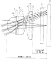
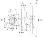
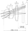
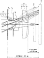
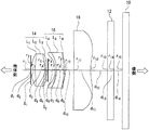
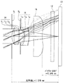
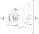
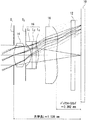
図1、図6、図11、図16、図21、図26、図31、図36、及び図41は、それぞれ実施例1〜実施例9の撮像レンズの構成図である。また、図2、図7、図12、図17、図22、図27、図32、図37、及び図42は、それぞれ実施例1〜実施例9の撮像レンズの光路図である。第1形態の撮像レンズにあっては、物体側から一つ目の接合型複合レンズを構成するサブレンズを第1サブレンズL1、第2サブレンズL2、第3サブレンズL3とし、二つ目の接合型複合レンズを構成するサブレンズを第4サブレンズL4、第5サブレンズL5、第6サブレンズL6としてある。第2形態の撮像レンズにあっては、接合型複合レンズを構成するサブレンズを第1サブレンズL1、第2サブレンズL2、第3サブレンズL3としてある。 1, 6, 11, 16, 21, 21, 26, 31, 36, and 41 are configuration diagrams of the imaging lenses of Examples 1 to 9, respectively. FIGS. 2, 7, 12, 17, 22, 22, 27, 32, 37, and 42 are optical path diagrams of the imaging lenses of Examples 1 to 9, respectively. In the imaging lens of the first form, the sub lenses constituting the first cemented compound lens from the object side are the first sub lens L 1 , the second sub lens L 2 , and the third sub lens L 3 , The sub lenses constituting the second junction type compound lens are a fourth sub lens L 4 , a fifth sub lens L 5 , and a sixth sub lens L 6 . In the imaging lens of the second form, the sub lenses constituting the junction type compound lens are the first sub lens L 1 , the second sub lens L 2 , and the third sub lens L 3 .
実施例1、4、及び7の撮像レンズにおいては、それぞれ、第1レンズ14と第2レンズ16との間に配置される絞りSは開口絞りとしての役割を果たし、入射瞳の位置を確定している。
In the imaging lenses of Examples 1, 4, and 7, the diaphragm S disposed between the
一方、実施例2、3、5、6、8、9の撮像レンズにおいては、第1レンズ14の前面に配置される第1絞りS1は開口絞りとしての役割を果たし、入射瞳の位置を確定する。また、第1レンズ14と第2レンズ16との間に配置される第2絞りS2は、画像のコントラストが減少する現象であるフレアー(flare)あるいは、画像の滲み現象であるスミア(smear)を防ぐ役割を果たす。
On the other hand, in the imaging lenses of Examples 2, 3, 5, 6, 8, and 9, the first diaphragm S 1 disposed in front of the
すなわち、実施例2、3、5、6、8、9の撮像レンズにおいては、第1絞りS1は、入射瞳の位置を確定し、Fナンバーを規定し、歪曲収差や非点収差等の緒収差特性を決定するするという撮像レンズの基本的特性を決定する役割を果たす絞りであるので、この発明では必須構成要素である。これに対して、第2絞りS2は、画像のコントラストの向上という付加的な特性を向上させるための構成要素であるので、設置することが望ましいが、設置しなくともこの発明の撮像レンズは成立する。 That is, in the imaging lenses of Examples 2, 3, 5, 6, 8, and 9, the first aperture stop S 1 determines the position of the entrance pupil, defines the F number, distortion aberration, astigmatism, etc. Since the stop serves to determine the basic characteristics of the imaging lens for determining the aberration characteristics, it is an essential component in the present invention. On the other hand, the second aperture stop S 2 is a component for improving the additional characteristic of improving the contrast of the image, so it is desirable to install it, but the imaging lens of the present invention can be installed without installing it. To establish.
誤解の生じない範囲でriを光軸上曲率半径の値を意味する変数として用いるほか、レンズやカバーガラス面あるいは撮像面を識別する記号(例えば、図1において、r1を、第1レンズ14の物体側の面の意味に用いる等)として用いることもある。図1、図6、図11、図16、図21、図26、図31、図36、及び図41に示すri及びdi、Nj、νj等のパラメータは、以下に示す表1〜表9に具体的数値として与えてある。ここで、i及びjは、それぞれ1以上の正の整数であって、物体側から像側に向かって1から順に、絞り、各レンズの面番号あるいはレンズの厚みもしくはレンズ面間隔等に対応させて付したものである。すなわち、
ri は i番目の面の光軸上曲率半径、
di は i番目の面からi+1番目の面までの距離、
Nj は 絞りも含めて数えて第j番目に当たるレンズ(あるいはサブレンズ)の屈折率、及び
νjは 絞りも含めて数えて第j番目に当たるレンズ(あるいはサブレンズ)の素材のアッベ数、
をそれぞれ示す。
In addition to using r i as a variable that represents the value of the radius of curvature on the optical axis within a range that does not cause misunderstanding, a symbol that identifies the lens, the cover glass surface, or the imaging surface (for example, r 1 in FIG. It may also be used as the meaning of 14 object-side surfaces. Parameters such as r i and d i , N j , and ν j shown in FIGS. 1, 6, 11, 16, 16, 21, 26, 31, 36, and 41 are shown in Table 1 below. ~ Table 9 gives specific numerical values. Here, i and j are positive integers of 1 or more respectively, and in order from 1 toward the image side from the object side, they correspond to the aperture, the surface number of each lens, the lens thickness, the lens surface interval, etc. It is attached. That is,
r i is the radius of curvature on the optical axis of the i-th surface,
d i is the distance from the i-th surface to the i + 1-th surface,
N j is the refractive index of the j-th lens (or sub-lens), including the stop, and ν j is the Abbe number of the material of the j-th lens (or sub-lens), including the stop,
Respectively.
図1、図6、図11、図16、図21、図26、図31、図36、及び図41において定義されている面ri及び面間隔diの記号は、図2、図7、図12、図17、図22、図27、図32、図37、及び図42においては、図面が煩雑になるのを防ぐため、省略してある。 1, 6, 11, 16, 21, 26, 31, 36, and 41, the symbols for the surface r i and the surface interval d i are as shown in FIGS. 12, FIG. 17, FIG. 22, FIG. 27, FIG. 32, FIG. 37, and FIG. 42 are omitted in order to prevent the drawings from becoming complicated.
図1、図6、図11、図16、図21、図26、図31、図36、及び図41においては、絞りの開口部を線分で示してある。これは、レンズ面から絞り面までの距離を定義するためには、絞り面と光軸との交点が明確に示されなければならないためである。また、実施例1〜実施例9の撮像レンズのそれぞれの断面図である、図2、図7、図12、図17、図22、図27、図32、図37、及び図42においては、上記の図1、図6、図11、図16、図21、図26、図31、図36、及び図41とは逆に、絞りの開口部を開けて、開口部の端を始点とした半直線で光を遮断する絞りの本体を示してある。これは、主光線等の光線を記入するために、絞りの実態を反映させて、絞りの開口部を開けて示す必要があるためである。 In FIGS. 1, 6, 11, 16, 21, 21, 26, 31, 36, and 41, the aperture of the diaphragm is shown by a line segment. This is because, in order to define the distance from the lens surface to the stop surface, the intersection between the stop surface and the optical axis must be clearly shown. In addition, each of the imaging lenses of Examples 1 to 9 is a cross-sectional view, in FIGS. 2, 7, 12, 12, 17, 22, 27, 32, 37, and 42, In contrast to FIGS. 1, 6, 11, 16, 21, 21, 26, 31, 36, and 41 described above, the aperture of the aperture is opened and the end of the aperture is the starting point. The main body of the diaphragm that blocks light in a half line is shown. This is because, in order to enter a light ray such as a principal ray, it is necessary to open and show the aperture of the aperture reflecting the actual state of the aperture.
光学長Lは、実施例1、4及び7の撮像レンズにおいては、第1レンズL1の物体側面r1から撮像面までの距離であり、実施例2、3、5、6、8、及び9の撮像レンズにおいては、第1絞りS1から撮像面までの距離である。バックフォーカスbfは、第3レンズ18の像側の面から撮像面までの距離である。ここでは、カバーガラスを取り除いて計測される第3レンズ18の像側の面から撮像面までの長さを、バックフォーカスbfとして表すものとする。ここで、第3レンズ18が接合型複合レンズである場合は、第3レンズ18の像側の面とは、第6サブレンズL6の像側の面(実施例7では、第3サブレンズL3の像側の面)を意味する。
Optical length L, in the imaging lens of Example 1, 4 and 7, the distance from the object side surface r 1 of the first lens L 1 to the imaging surface, Examples 2,3,5,6,8 and, in 9 of the imaging lens, a distance from the diaphragm S 1 to the imaging surface. The back focus bf is a distance from the image side surface of the
表1〜表9は、それぞれ実施例1〜実施例9の撮像レンズを構成する第1〜第3レンズ、あるいは第1〜第6サブレンズ(実施例7〜9の撮像レンズにあっては第1〜第3サブレンズ)の厚みや、これらのレンズを構成する曲面の曲率半径、これらのレンズの配置間隔及びこれらのレンズと絞りとの配置関係等に関するデータを示す。非球面データは、表1〜表9のそれぞれの欄に面番号とともに示した。また、光軸上曲率半径の値riは、物体側に凸である場合を正の値、像側に凸である場合を負の値として示してある。 Tables 1 to 9 show the first to third lenses or the first to sixth sub-lenses constituting the imaging lenses of Examples 1 to 9, respectively (the imaging lenses of Examples 7 to 9 are the first ones). Data on the thickness of the first to third sublenses), the radius of curvature of the curved surfaces constituting these lenses, the arrangement interval of these lenses, the arrangement relationship between these lenses and the stop, and the like are shown. The aspheric data is shown together with the surface number in each column of Tables 1-9. Further, the value r i of the radius of curvature on the optical axis is shown as a positive value when convex on the object side and as a negative value when convex on the image side.
第2サブレンズあるいは第5サブレンズが平行平面ガラス板である場合の両面、絞りS、第1絞りS1、第2絞りS2、及びカバーガラス(あるいはフィルター等)の両面は、平面であるので曲率半径は、∞と表示している。また、撮像面については、平面であるから、固体撮像素子10の撮像面を表す曲率半径について∞とすべきところを省略してある。
When the second sub lens or the fifth sub lens is a plane parallel glass plate, both surfaces of the diaphragm S, the first diaphragm S 1 , the second diaphragm S 2 , and the cover glass (or filter, etc.) are planar. Therefore, the radius of curvature is displayed as ∞. Further, since the imaging surface is a flat surface, the place where the curvature radius representing the imaging surface of the solid-
この発明で使用される非球面は、次の式で与えられる。 The aspherical surface used in the present invention is given by the following equation.
Z = ch2/[1 + [1−(1+k)c2h2]+1/2]+A0h4+B0h6+C0h8+D0h10
ただし、
Z : 面頂点に対する接平面からの深さ
c : 面の光軸上の曲率
h : 光軸からの高さ
k : 円錐定数
A0: 4次の非球面係数
B0: 6次の非球面係数
C0: 8次の非球面係数
D0: 10次の非球面係数
である。
Z = ch 2 / [1 + [1− (1 + k) c 2 h 2 ] +1/2 ] + A 0 h 4 + B 0 h 6 + C 0 h 8 + D 0 h 10
However,
Z: Depth from tangent plane to face vertex
c: curvature on the optical axis of the surface
h: Height from the optical axis
k: Conical constant
A 0 : Fourth-order aspheric coefficient
B 0 : 6th-order aspheric coefficient
C 0 : 8th-order aspheric coefficient
D 0 : 10th-order aspheric coefficient.
この明細書中の表1〜表9において、円錐定数(k)及び非球面係数(A0、B0、C0及びD0)を示す数値は指数表示であり、例えば「e−1」は、「10の−1乗」を意味する。 In Tables 1 to 9 in this specification, the numerical values indicating the conic constant (k) and the aspherical coefficients (A 0 , B 0 , C 0 and D 0 ) are expressed in exponents, for example, “e−1” is , "10 to the power of -1".
以下、図1〜図45を参照して実施例1〜実施例9の撮像レンズを説明する。 Hereinafter, the imaging lenses of Examples 1 to 9 will be described with reference to FIGS.
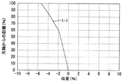
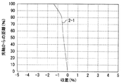
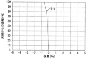
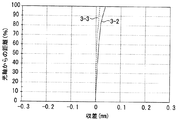
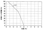
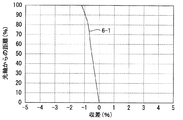
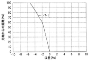
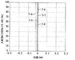
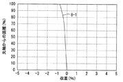
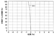
図3、図8、図13、図18、図23、図28、図33、図38及び図43に示す歪曲収差曲線は、光軸からの距離(縦軸に像面内での光軸からの最大距離を100として百分率表示してある。)に対して、収差(横軸に正接条件の不満足量を百分率表示してある。)を示した。 The distortion curve shown in FIGS. 3, 8, 13, 18, 23, 28, 33, 38 and 43 is the distance from the optical axis (the vertical axis is the optical axis in the image plane). Aberrations (the amount of dissatisfaction of the tangent condition is displayed as a percentage on the horizontal axis) are shown.
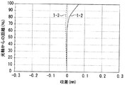
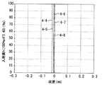
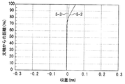
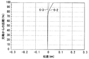
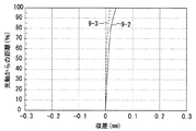
図4、図9、図14、図19、図24、図29、図34、図39及び図44に示す非点収差曲線は、歪曲収差曲線と同様に、縦軸に示す光軸からの距離(%)に対して、収差量(mm単位)を横軸にとって示し、メリジオナル面とサジタル面とにおける収差量を、それぞれ表示した。 The astigmatism curves shown in FIGS. 4, 9, 14, 19, 24, 29, 34, 39, and 44 are the distance from the optical axis shown on the vertical axis, similar to the distortion curves. With respect to (%), the amount of aberration (in mm) is shown on the horizontal axis, and the amounts of aberration on the meridional surface and the sagittal surface are respectively displayed.
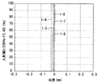
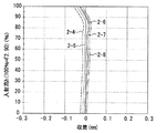
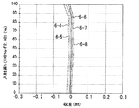
図5、図10、図15、図20、図25、図30、図35、図40及び図45に示す色・球面収差曲線においては、縦軸の入射高hに対して、収差量(mm単位)を横軸にとって示した。縦軸の入射高hは、Fナンバーに換算して示してある。例えば、開放Fナンバーが3.40のレンズに対しては、縦軸の入射高h=100%が、F=3.40に対応する。開放Fナンバーとは、開口絞りの直径を、設計上の最大の大きさとした場合のFナンバーを意味する。 In the chromatic / spherical aberration curves shown in FIG. 5, FIG. 10, FIG. 15, FIG. 20, FIG. 25, FIG. 30, FIG. Units are shown on the horizontal axis. The incident height h on the vertical axis is shown in terms of F number. For example, for a lens with an open F number of 3.40, an incident height h = 100% on the vertical axis corresponds to F = 3.40. The open F number means the F number when the diameter of the aperture stop is the maximum design.
また、色・球面収差曲線においては、C線(波長656.3nmの光)、d線(波長587.6 nmの光)、e線(波長546.1 nmの光)、F線(波長486.1 nmの光)及びg線(波長435.8 nmの光)に対する収差値を示した。 In the chromatic / spherical aberration curve, C line (light with a wavelength of 656.3 nm), d line (light with a wavelength of 587.6 nm), e line (light with a wavelength of 546.1 nm), F line (light with a wavelength of 486.1 nm) and The aberration values for g-line (light with a wavelength of 435.8 nm) are shown.
実施例1〜実施例9において、第1サブレンズ、第3サブレンズ、第4サブレンズ、及び第6サブレンズの素材(実施例7〜実施例9においては、第1サブレンズ及び第3サブレンズの素材)に、硬化性樹脂材料である透明硬化性シリコーン樹脂を用いた。また、第2サブレンズ及び第5サブレンズの素材(実施例7〜実施例9においては、第2サブレンズの素材)に、ガラス材料である光学ガラス(BK7等)を用いた。ここで、BK7とは、ショットガラス(SCHOTT GLAS)社が硼珪酸ガラス(borosilicate glass)のグループに付けた名称である。光学ガラスBK7は、現在、複数のガラスメーカーによって製造されている。市販されている光学ガラスBK7の屈折率及びアッベ数は、製造会社あるいは製造ロットによって多少の相違がある。 In Example 1 to Example 9, the material of the first sub lens, the third sub lens, the fourth sub lens, and the sixth sub lens (in Example 7 to Example 9, the first sub lens and the third sub lens A transparent curable silicone resin, which is a curable resin material, was used as the lens material. Moreover, optical glass (BK7 etc.) which is a glass material was used for the material of the second sub lens and the fifth sub lens (in Example 7 to Example 9, the material of the second sub lens). Here, BK7 is a name given by Schott Glass Co. to a group of borosilicate glass. The optical glass BK7 is currently manufactured by a plurality of glass manufacturers. The refractive index and Abbe number of the commercially available optical glass BK7 vary somewhat depending on the manufacturer or the production lot.
透明硬化性シリコーン樹脂とは、可視光に対して透明であって、かつ一時的に150℃程度の高温環境となっても、レンズの幾何学的形状は変化せず、その光学的性能が劣化しないシリコーン樹脂を意味する。ここでいう透明硬化性シリコーン樹脂は、例えば、シリコーン樹脂の供給会社から、「透明高硬度シリコーン樹脂」との名称で市販されているシリコーン樹脂の中から適宜選択することができる。 Transparent curable silicone resin is transparent to visible light, and even if it temporarily becomes a high temperature environment of about 150 ° C, the geometrical shape of the lens does not change and its optical performance deteriorates. Does not mean silicone resin. The transparent curable silicone resin here can be appropriately selected from, for example, silicone resins commercially available under the name of “transparent high hardness silicone resin” from a silicone resin supplier.
第3レンズ18と固体撮像素子(solid-state image sensor)10との間には、カバーガラス12が挿入されている。カバーガラス12の素材は、屈折率(d線(587.6 nmの光)に対する値)が1.51633、アッベ数が64.0である光学ガラスBK7である。後述する表1〜表6において、カバーガラス12の屈折率及びアッベ数は、それぞれ、N=1.51633、ν=64.0と示してある。
A
以下に、実施例1〜実施例9に関する構成レンズの曲率半径ri(mm単位)、レンズ面間隔di(mm単位)、レンズ素材の屈折率、レンズ素材のアッベ数、円錐定数k及び非球面係数(A0、B0、C0及びD0)を表1〜表9に一覧にして掲げる。なお、表1〜表9における構成レンズの光軸上曲率半径の値及びレンズ面間隔は、実施例1〜実施例9のそれぞれの撮像レンズの合成焦点距離fの値を1.00 mmに正規化した時の値として示してある。 Hereinafter, the curvature radii r i (unit: mm) of the constituent lenses related to Example 1 to Example 9, lens surface distance d i (unit: mm), refractive index of lens material, Abbe number of lens material, conic constant k and non- The spherical coefficients (A 0 , B 0 , C 0 and D 0 ) are listed in Tables 1 to 9. In addition, the value of the curvature radius on the optical axis and the lens surface interval of the constituent lenses in Tables 1 to 9 were normalized to 1.00 mm for the combined focal length f of each imaging lens of Examples 1 to 9. It is shown as the hour value.
第1レンズ14、第2レンズ16、及び第3レンズ18の両側面は、いずれも非球面レンズとした。第1レンズ14、第2レンズ16、及び第3レンズ18が接合型複合レンズである場合は、接合型複合レンズを構成する第1サブレンズの物体側面及び第3サブレンズの像側面が非球面であり、また、第4サブレンズの物体側面及び第6サブレンズの像側面が非球面である。
Both side surfaces of the
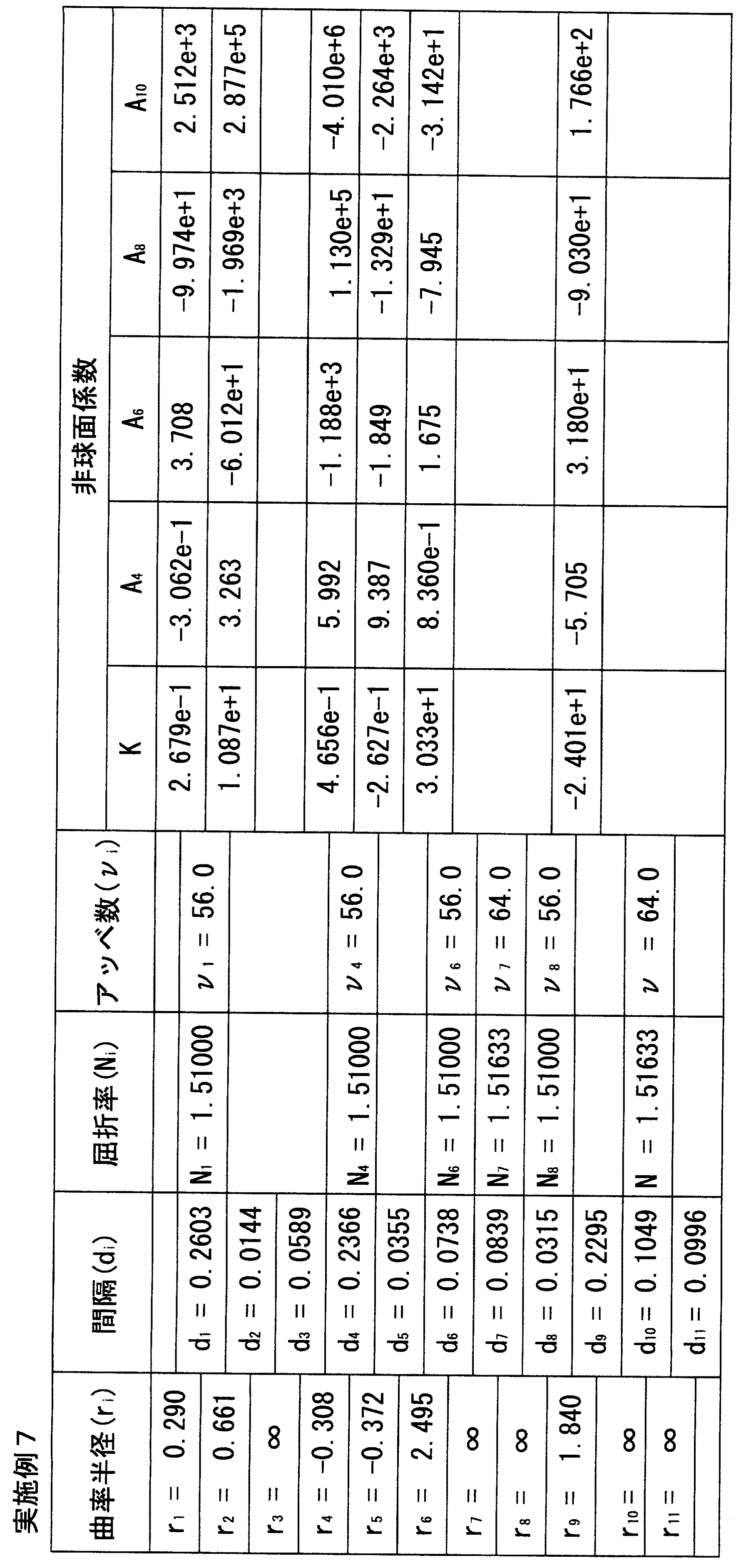
実施例1〜9において使用された第1〜第6サブレンズ(実施例7〜9にあっては、第1〜第3サブレンズ)及び、第1〜3レンズとして使用された単レンズの構成材料である、硬化性樹脂材料である熱硬化性シリコーン樹脂あるいは、高軟化温度の光学レンズの形成用材料である光学ガラスの屈折率及びアッベ数は、製造会社ごとに異なる他、同一の商品名であっても屈折率及びアッベ数は多少の相違がある。以下に示す実施例1〜9において、実施例ごとに、使用した熱硬化性のシリコーン樹脂材料及び光学ガラス材料を示すと共に、これらの屈折率(d線(587.6 nmの光)に対する値)、及びアッベ数を示す。 Configurations of first to sixth sub lenses used in Examples 1 to 9 (first to third sub lenses in Examples 7 to 9) and single lenses used as first to third lenses The refractive index and Abbe number of the thermosetting silicone resin, which is the material, or the optical glass, which is the material for forming the high-softening temperature optical lens, differ from manufacturer to manufacturer. Even so, the refractive index and the Abbe number are slightly different. In Examples 1 to 9 shown below, the thermosetting silicone resin material and optical glass material used are shown for each example, and their refractive indices (values for d-line (light at 587.6 nm)), and Indicates the Abbe number.
<実施例1>
実施例1の撮像レンズは、この発明の第1形態の撮像レンズであって、第1の撮像レンズの実施例であり、図1及び図2に示すように、第1レンズ14と、開口絞りSと、第2レンズ16及び第3レンズ18とを具え、物体側から像側に向って、第1レンズ14、開口絞りS、第2レンズ16、第3レンズ18の順に配列されて構成されている。
<Example 1>
The imaging lens of Example 1 is the imaging lens according to the first aspect of the present invention, and is an example of the first imaging lens. As shown in FIGS. 1 and 2, the
第1レンズ14には、単レンズが用いられている。第2レンズ16は、物体側から像側に向って、第1サブレンズL1、第2サブレンズL2及び第3サブレンズL3の順に配列され、第1サブレンズL1と第2サブレンズL2とが接着され、かつ第2サブレンズL2と第3サブレンズL3とが接着された状態の接合型複合レンズである。第3レンズ18は、物体側から像側に向って、第4サブレンズL4、第5サブレンズL5及び第6サブレンズL6の順に配列され、第4サブレンズL4と第5サブレンズL5とが接着され、かつ第5サブレンズL5と第6サブレンズL6とが接着された状態の接合型複合レンズである。
A single lens is used for the
実施例1の撮像レンズは、第1レンズ14が、富士高分子工業株式会社(Fuji Polymer Industries Co., Ltd.)製の透明硬化性シリコーン樹脂SMX-7852で形成されている。硬化性樹脂材料であるこの透明硬化性シリコーン樹脂SMX-7852は、熱硬化性のシリコーン樹脂材料であり、金型(Die)を用いて射出成形することで形成できる。また、第1、第3、第4、及び第6サブレンズも、透明硬化性シリコーン樹脂SMX-7852(富士高分子工業株式会社製)で形成され、第2サブレンズL2、及び第5サブレンズL5が、HOYA株式会社(HOYA Corporation)製の光学ガラスBK7を用いて形成されている。
(A)第1サブレンズL1の屈折率N4は、N4=1.51000である。
(B)第2サブレンズL2の屈折率N5は、N5=1.51633である。
(C)第3サブレンズL3の屈折率N6は、N6=1.51000である。
(D)第1サブレンズL1のアッベ数ν4は、ν4=56.0である。
(E)第2サブレンズL2のアッベ数ν5は、ν5=64.0である。
(F)第3サブレンズL3のアッベ数ν6は、ν6=56.0である。
(G)第4サブレンズL4の屈折率N8は、N8=1.51000である。
(H)第5サブレンズL5の屈折率N9は、N9=1.51633である。
(I)第6サブレンズL6の屈折率N10は、N10=1.51000である。
(J)第4サブレンズL4のアッベ数ν8は、ν8=56.0である。
(K)第5サブレンズL5のアッベ数ν9は、ν9=64.0である。
(L)第6サブレンズL6のアッベ数ν10は、ν10=56.0である。
In the imaging lens of Example 1, the
(A) The refractive index N 4 of the first sub-lens L 1 is N 4 = 1.51000.
(B) The refractive index N 5 of the second sub-lens L 2 is N 5 = 1.51633.
(C) The refractive index N 6 of the third sub-lens L 3 is N 6 = 1.51000.
(D) The Abbe number ν 4 of the first sub lens L 1 is ν 4 = 56.0.
(E) The Abbe number ν 5 of the second sub lens L 2 is ν 5 = 64.0.
(F) The Abbe number ν 6 of the third sub lens L 3 is ν 6 = 56.0.
(G) The refractive index N 8 of the fourth sub lens L 4 is N 8 = 1.51000.
(H) The refractive index N 9 of the fifth sub-lens L 5 is N 9 = 1.51633.
(I) The refractive index N 10 of the sixth sub-lens L 6 is N 10 = 1.51000.
(J) The Abbe number ν 8 of the fourth sub lens L 4 is ν 8 = 56.0.
(K) The Abbe number ν 9 of the fifth sub-lens L 5 is ν 9 = 64.0.
(L) The Abbe number ν 10 of the sixth sub lens L 6 is ν 10 = 56.0.
従って、|N5-N4|=|N5-N6|=|N9-N8|=|N9-N10|=0.00633であるので、下記の条件(1-1)、(1-2)、(1-5)、及び(1-6)を満たしている。また、|ν5-ν4|=|ν5-ν6|=|ν9-ν8|=|ν9-ν10|=8.0であるので、下記の条件(1-3)、(1-4)、(1-7)、及び(1-8)を満たしている。 Therefore, | N 5 -N 4 | = | N 5 -N 6 | = | N 9 -N 8 | = | N 9 -N 10 | = 0.00633. Therefore, the following conditions (1-1), (1 -2), (1-5), and (1-6) are satisfied. Since | ν 5 −ν 4 | = | ν 5 −ν 6 | = | ν 9 -ν 8 | = | ν 9 -ν 10 | = 8.0, the following conditions (1-3), (1 -4), (1-7), and (1-8) are satisfied.
条件(1-1)、(1-2)、(1-5)、及び(1-6)とは、それぞれ、以下に示す式(1-1)、(1-2)、(1-5)、及び(1-6)で与えられる条件を意味する。また、条件(1-3)、(1-4)、(1-7)、及び(1-8)とは、それぞれ、以下に示す式(1-3)、(1-4)、(1-7)、及び(1-8)で与えられる条件を意味する。 Conditions (1-1), (1-2), (1-5), and (1-6) are respectively the following formulas (1-1), (1-2), (1-5) ) And the conditions given in (1-6). Conditions (1-3), (1-4), (1-7), and (1-8) are the following expressions (1-3), (1-4), (1 -7) and the conditions given in (1-8).
0≦|N5-N4|≦0.1 (1-1)
0≦|N5-N6|≦0.1 (1-2)
0≦|ν5-ν4|≦30.0 (1-3)
0≦|ν5-ν6|≦30.0 (1-4)
0≦|N9-N8|≦0.1 (1-5)
0≦|N9-N10|≦0.1 (1-6)
0≦|ν9-ν8|≦30.0 (1-7)
0≦|ν9-ν10|≦30.0 (1-8)
ただし、
N4:前記第1サブレンズの屈折率
N5:前記第2サブレンズの屈折率
N6:前記第3サブレンズの屈折率
ν4:前記第1サブレンズのアッベ数
ν5:前記第2サブレンズのアッベ数
ν6:前記第3サブレンズのアッベ数
N8:前記第4サブレンズの屈折率
N9:前記第5サブレンズの屈折率
N10:前記第6サブレンズの屈折率
ν8:前記第4サブレンズのアッベ数
ν9:前記第5サブレンズのアッベ数
ν10:前記第6サブレンズのアッベ数
である。
0 ≦ | N 5 -N 4 | ≦ 0.1 (1-1)
0 ≦ | N 5 -N 6 | ≦ 0.1 (1-2)
0 ≦ | ν 5 -ν 4 | ≦ 30.0 (1-3)
0 ≦ | ν 5 -ν 6 | ≦ 30.0 (1-4)
0 ≦ | N 9 -N 8 | ≦ 0.1 (1-5)
0 ≦ | N 9 -N 10 | ≦ 0.1 (1-6)
0 ≦ | ν 9 -ν 8 | ≦ 30.0 (1-7)
0 ≦ | ν 9 -ν 10 | ≦ 30.0 (1-8)
However,
N 4 : refractive index of the first sub-lens
N 5 : refractive index of the second sub-lens
N 6 : Refractive index of the third sub lens ν 4 : Abbe number of the first sub lens ν 5 : Abbe number of the second sub lens ν 6 : Abbe number of the third sub lens
N 8 : refractive index of the fourth sub-lens
N 9 : refractive index of the fifth sub-lens
N 10 : refractive index of the sixth sub lens ν 8 : Abbe number of the fourth sub lens ν 9 : Abbe number of the fifth sub lens ν 10 : Abbe number of the sixth sub lens
条件(1-1)〜(1-8)とは、それぞれ式(1-1)〜(1-8)で与えられる条件を意味することは、以後の説明(実施例4の説明)においても同様である。 The conditions (1-1) to (1-8) mean the conditions given by the expressions (1-1) to (1-8), respectively, in the following description (description of Example 4). It is the same.
図2に実施例1の撮像レンズの光路図を示す。図2に示すとおり、開口絞りSは、第1レンズ14と第2レンズ16との間に設けられている。開口絞りSの絞り面は平面であるので、表1にr3=∞と示してある。また開放FナンバーFnoは、3.40である。
FIG. 2 shows an optical path diagram of the imaging lens of the first embodiment. As shown in FIG. 2, the aperture stop S is provided between the
表1に示すとおり、r5=∞及びr6=∞であることから、第2レンズ16を構成する第2サブレンズL2は、平行平面ガラス板であり、r9=∞及びr10=∞であることから、第3レンズ18を構成する第5サブレンズL5は、平行平面ガラス板である。
As shown in Table 1, since r 5 = ∞ and r 6 = ∞, the second sub lens L 2 constituting the
また、r1が正の値であってr2が正の値であるから、第1レンズ14は、近軸上で、物体側に凸面を向けたメニスカスレンズである。
Since r 1 is a positive value and r 2 is a positive value, the
また、r4が負の値であるから、第2レンズ16を構成するサブレンズのうち、第1サブレンズL1は、近軸上で当該第1サブレンズL1の物体側面が物体側に凹面を向けた平凹レンズであり、及びr7も負の値であるから、第3サブレンズL3は、近軸上で当該第3サブレンズL3の像側面が像側に凸面を向けた平凸レンズである。
Further, since r 4 is a negative value, among the sub-lenses constituting the
また、r8が正の値であるから、第3レンズ18を構成するサブレンズのうち、第4サブレンズL4は、近軸上で当該第4サブレンズL4の物体側面が物体側に凸面を向けた平凸レンズであり、r11も正の値であるから、第6サブレンズL6も、近軸上で当該第6サブレンズL6の像側面が像側に凹面を向けた平凹レンズである。
Further, since r 8 is a positive value, among the sub-lenses constituting the
図2に示すとおり、焦点距離f=1.00 mmに対する光学長Lは1.229 mmであり、バックフォーカスbfは0.400 mmである。 As shown in FIG. 2, the optical length L with respect to the focal length f = 1.00 mm is 1.229 mm, and the back focus bf is 0.400 mm.
図3に示す歪曲収差曲線1-1、図4に示す非点収差曲線(メリジオナル面に対する収差曲線1-2及びサジタル面に対する収差曲線1-3)、図5に示す色・球面収差曲線(g線に対する収差曲線1-4、F線に対する収差曲線1-5、e線に対する収差曲線1-6、d線に対する収差曲線1-7、及びC線に対する収差曲線1-8、)について、それぞれグラフによって示してある。 Distortion curve 1-1 shown in FIG. 3, astigmatism curve shown in FIG. 4 (aberration curve 1-2 for meridional surface and aberration curve 1-3 for sagittal surface), chromatic / spherical aberration curve (g Aberration curve 1-4 for line, aberration curve 1-5 for F line, aberration curve 1-6 for e line, aberration curve 1-7 for d line, and aberration curve 1-8 for C line) It is indicated by
図3及び図4の収差曲線の縦軸は、像高を光軸からの距離の何%であるかで示している。図3及び図4中で、100%は0.586 mmに対応している。また、図5の収差曲線の縦軸は、入射高h(Fナンバー)を示しており、最大が3.40に対応する。図3の横軸は収差(%)を示し、図4、図5の横軸は、収差の大きさ(mm)を示している。 The vertical axis of the aberration curves in FIGS. 3 and 4 shows the image height as a percentage of the distance from the optical axis. 3 and 4, 100% corresponds to 0.586 mm. In addition, the vertical axis of the aberration curve in FIG. 5 indicates the incident height h (F number), and the maximum corresponds to 3.40. The horizontal axis in FIG. 3 indicates aberration (%), and the horizontal axes in FIGS. 4 and 5 indicate the magnitude of aberration (mm).
歪曲収差は、像高100%(像高 0.586 mm)の位置において収差量の絶対値が5.38%と最大になっており、像高0.586 mm以下の範囲で収差量の絶対値が5.38%以内に収まっている。 For distortion, the absolute value of the aberration is maximum at 5.38% at an image height of 100% (image height 0.586 mm), and the absolute value of the aberration is within 5.38% within an image height of 0.586 mm or less. It is settled.
非点収差は、像高100%(像高0.586 mm)の位置においてメリジオナル面における収差量の絶対値が0.0643 mmと最大になっており、また、像高0.586 mm以下の範囲で収差量の絶対値が0.0643 mm以内に収まっている。 Astigmatism has a maximum absolute value of 0.0643 mm on the meridional surface at an image height of 100% (image height of 0.586 mm), and the absolute value of aberration in the range of image height of 0.586 mm or less. The value is within 0.0643 mm.
色・球面収差は、入射高hの100% においてg線に対する収差曲線1-4の絶対値が0.0231 mmと最大になっており、収差量の絶対値が0.0231 mm以内に収まっている。 For the chromatic / spherical aberration, the absolute value of the aberration curve 1-4 on the g-line is 0.0231 mm, which is the maximum, at 100% entrance height h, and the absolute value of the aberration is within 0.0231 mm.
従って、実施例1の撮像レンズによれば、携帯電話器等に搭載可能な程度に光学長が短く、撮像レンズと撮像面との間にフィルタやカバーガラス等の部品を挿入することが可能な程度にバックフォーカスが長く、かつ良好な画像が得られる。 Therefore, according to the imaging lens of Example 1, the optical length is short enough to be mounted on a mobile phone or the like, and it is possible to insert components such as a filter and a cover glass between the imaging lens and the imaging surface. As long as the back focus is long, a good image can be obtained.
<実施例2>
実施例2の撮像レンズは、この発明の第1形態の撮像レンズであって、この発明の第2の撮像レンズの実施例であり、図6及び図7に示すように、開口絞り(第1絞り)S1と、第1レンズ14と、第2絞りS2と、第2レンズ16と、第3レンズ18とを具え、物体側から像側に向って、開口絞りS1、第1レンズ14、第2絞りS2、第2レンズ16、第3レンズ18の順に配列されて構成されている。
<Example 2>
The imaging lens of Example 2 is the imaging lens according to the first aspect of the present invention, and is an example of the second imaging lens of the present invention.As shown in FIG. 6 and FIG. (Aperture) S 1 ,
第2レンズ16には、単レンズが用いられている。第1レンズ14は、物体側から像側に向って、第1サブレンズL1、第2サブレンズL2及び第3サブレンズL3の順に配列され、第1サブレンズL1と第2サブレンズL2とが接着され、かつ第2サブレンズL2と第3サブレンズL3とが接着された状態の接合型複合レンズである。第3レンズ18は、物体側から像側に向って、第4サブレンズL4、第5サブレンズL5及び第6サブレンズL6の順に配列され、第4サブレンズL4と第5サブレンズL5とが接着され、かつ第5サブレンズL5と第6サブレンズL6とが接着された状態の接合型複合レンズである。
A single lens is used for the
実施例2の撮像レンズは、第2レンズ16が、光学ガラスBK7で形成されている。第1、第3、第4、及び第6サブレンズは、硬化性樹脂材料である透明硬化性シリコーン樹脂SMX-7852(富士高分子工業株式会社製)で形成され、第2及び第5サブレンズは、HOYA株式会社製の光学ガラスBK7を用いて形成されている。
(A)第1サブレンズL1の屈折率N2は、N2=1.51000である。
(B)第2サブレンズL2の屈折率N3は、N3=1.51633である。
(C)第3サブレンズL3の屈折率N4は、N4=1.51000である。
(D)第1サブレンズL1のアッベ数ν2は、ν2=56.0である。
(E)第2サブレンズL2のアッベ数ν3は、ν3=64.0である。
(F)第3サブレンズL3のアッベ数ν4は、ν4=56.0である。
(G)第4サブレンズL4の屈折率N9は、N9=1.51000である。
(H)第5サブレンズL5の屈折率N10は、N10=1.51633である。
(I)第6サブレンズL6の屈折率N11は、N11=1.51000である。
(J)第4サブレンズL4のアッベ数ν9は、ν9=56.0である。
(K)第5サブレンズL5のアッベ数ν10は、ν10=64.0である。
(L)第6サブレンズL6のアッベ数ν11は、ν11=56.0である。
In the imaging lens of Example 2, the
(A) The refractive index N 2 of the first sub-lens L 1 is N 2 = 1.51000.
(B) The refractive index N 3 of the second sub lens L 2 is N 3 = 1.51633.
(C) The refractive index N 4 of the third sub-lens L 3 is N 4 = 1.51000.
(D) The Abbe number ν 2 of the first sub lens L 1 is ν 2 = 56.0.
(E) The Abbe number ν 3 of the second sub-lens L 2 is ν 3 = 64.0.
(F) The Abbe number ν4 the third sub-lens L 3 is ν 4 = 56.0.
(G) The refractive index N 9 of the fourth sub lens L 4 is N 9 = 1.51000.
(H) The refractive index N 10 of the fifth sub lens L 5 is N 10 = 1.51633.
(I) The refractive index N 11 of the sixth sub-lens L 6 is N 11 = 1.51000.
(J) The Abbe number ν 9 of the fourth sub lens L 4 is ν 9 = 56.0.
(K) The Abbe number ν 10 of the fifth sub lens L 5 is ν 10 = 64.0.
(L) The Abbe number ν 11 of the sixth sub lens L 6 is ν 11 = 56.0.
従って、|N3-N2|=|N3-N4|=|N10-N9|=|N10-N11|=0.00633であるので、下記の条件(2-1)、(2-2)、(2-5)、及び(2-6)を満たしている。また、|ν3-ν2|=|ν3-ν4|=|ν10-ν9|=|ν10-ν11|=8.0であるので、下記の条件(2-3)、(2-4)、(2-7)、及び(2-8)を満たしている。 Therefore, | N 3 -N 2 | = | N 3 -N 4 | = | N 10 -N 9 | = | N 10 -N 11 | = 0.00633. Therefore, the following conditions (2-1) and (2 -2), (2-5), and (2-6) are satisfied. Since | ν 3 −ν 2 | = | ν 3 −ν 4 | = | ν 10 -ν 9 | = | ν 10 -ν 11 | = 8.0, the following conditions (2-3), (2 -4), (2-7), and (2-8) are satisfied.
条件(2-1)、(2-2)、(2-5)、及び(2-6)とは、それぞれ、以下に示す式(2-1)、(2-2)、(2-5)、及び(2-6)で与えられる条件を意味する。また、条件(2-3)、(2-4)、(2-7)、及び(2-8)とは、それぞれ、以下に示す式(2-3)、(2-4)、(2-7)、及び(2-8)で与えられる条件を意味する。 Conditions (2-1), (2-2), (2-5), and (2-6) are the following expressions (2-1), (2-2), (2-5) ) And the conditions given in (2-6). The conditions (2-3), (2-4), (2-7), and (2-8) are the expressions (2-3), (2-4), (2 -7) and the conditions given in (2-8).
0≦|N3-N2|≦0.1 (2-1)
0≦|N3-N4|≦0.1 (2-2)
0≦|ν3-ν2|≦30.0 (2-3)
0≦|ν3-ν4|≦30.0 (2-4)
0≦|N10-N9|≦0.1 (2-5)
0≦|N10-N11|≦0.1 (2-6)
0≦|ν10-ν9|≦30.0 (2-7)
0≦|ν10-ν11|≦30.0 (2-8)
ただし、
N2:前記第1サブレンズの屈折率
N3:前記第2サブレンズの屈折率
N4:前記第3サブレンズの屈折率
ν2:前記第1サブレンズのアッベ数
ν3:前記第2サブレンズのアッベ数
ν4:前記第3サブレンズのアッベ数
N9:前記第4サブレンズの屈折率
N10:前記第5サブレンズの屈折率
N11:前記第6サブレンズの屈折率
ν9:前記第4サブレンズのアッベ数
ν10:前記第5サブレンズのアッベ数
ν11:前記第6サブレンズのアッベ数
である。
0 ≦ | N 3 -N 2 | ≦ 0.1 (2-1)
0 ≦ | N 3 -N 4 | ≦ 0.1 (2-2)
0 ≦ | ν 3 -ν 2 | ≦ 30.0 (2-3)
0 ≦ | ν 3 -ν 4 | ≦ 30.0 (2-4)
0 ≦ | N 10 -N 9 | ≦ 0.1 (2-5)
0 ≦ | N 10 -N 11 | ≦ 0.1 (2-6)
0 ≦ | ν 10 -ν 9 | ≦ 30.0 (2-7)
0 ≦ | ν 10 -ν 11 | ≦ 30.0 (2-8)
However,
N 2 : refractive index of the first sub-lens
N 3 : refractive index of the second sub-lens
N 4 : Refractive index of the third sub lens ν 2 : Abbe number of the first sub lens ν 3 : Abbe number of the second sub lens ν 4 : Abbe number of the third sub lens
N 9 : Refractive index of the fourth sub lens
N 10 : refractive index of the fifth sub-lens
N 11 : refractive index of the sixth sub lens ν 9 : Abbe number of the fourth sub lens ν 10 : Abbe number of the fifth sub lens ν 11 : Abbe number of the sixth sub lens
条件(2-1)〜(2-8)とは、それぞれ式(2-1)〜(2-8)で与えられる条件を意味することは、以後の説明(実施例5の説明)においても同様である。 The conditions (2-1) to (2-8) mean the conditions given by the expressions (2-1) to (2-8), respectively, in the following description (description of Example 5). It is the same.
図6に実施例2の撮像レンズの断面図を示す。図6に示すとおり、開口絞りの役割を果たす第1絞りS1は、第1レンズ14を構成する第1サブレンズL1の第1面(物体側の面)と光軸との交点の位置に設けられている。フレアーあるいは、スミアを防ぐ役割を果たす第2絞りS2は、第1レンズ14と第2レンズ16との間に設けられている。
FIG. 6 shows a cross-sectional view of the imaging lens of the second embodiment. As shown in FIG. 6, the first stop S 1 serving as an aperture stop is the position of the intersection of the first surface (object side surface) of the first sub-lens L 1 constituting the
第1絞りS1の絞り面は、平面r1で構成されているので、表2にr1=∞と示してある。第2絞りS2は、平面r6で構成されているので、表2にr6=∞と示してある。また開放FナンバーFnoは、2.90である。 Since the diaphragm surface of the first diaphragm S 1 is composed of the plane r 1 , r 1 = ∞ is shown in Table 2. Since the second aperture stop S 2 is composed of the plane r 6 , r 6 = ∞ is shown in Table 2. The open F number Fno is 2.90.
表2に示すとおり、r3=∞及びr4=∞であることから、第1レンズ14を構成する第2サブレンズL2は、平行平面ガラス板であり、r10=∞及びr11=∞であることから、第3レンズ18を構成する第5サブレンズL5は、平行平面ガラス板である。
As shown in Table 2, since r 3 = ∞ and r 4 = ∞, the second sub-lens L 2 constituting the
また、r7が負の値であってr8も負の値であるから、第2レンズ16は、近軸上で、像側に凸面を向けたメニスカスレンズである。
Since r 7 is a negative value and r 8 is also a negative value, the
また、r2が正の値であるから、第1レンズ14を構成する第1サブレンズL1は、近軸上で当該第1サブレンズL1の物体側面が物体側に凸面を向けた平凸レンズであり、r5が負の値であるから、第3サブレンズL3は、近軸上で当該第3サブレンズL3の像側面が像側に凸面を向けた平凸レンズである。
Further, r 2 is from a positive value, the first sub-lens L 1 constituting the
また、r9が正の値であるから、第3レンズ18を構成する第4サブレンズL4は、近軸上で当該第4サブレンズL4の物体側面が物体側に凸面を向けた平凸レンズであり、r12も正の値であるから、第6サブレンズL6は、近軸上で当該第6サブレンズL6の像側面が像側に凹面を向けた平凹レンズである。
Further, r 9 is from a positive value, the fourth sub-lens L 4 constituting the
図7に示すとおり、焦点距離f=1.00 mmに対する光学長Lは1.080 mmであり、バックフォーカスbfは0.354 mmである。 As shown in FIG. 7, the optical length L with respect to the focal length f = 1.00 mm is 1.080 mm, and the back focus bf is 0.354 mm.
図8に示す歪曲収差曲線2-1、図9に示す非点収差曲線(メリジオナル面に対する収差曲線2-2及びサジタル面に対する収差曲線2-3)、図10に示す色・球面収差曲線(g線に対する収差曲線2-4、F線に対する収差曲線2-5、e線に対する収差曲線2-6、d線に対する収差曲線2-7、及びC線に対する収差曲線2-8、)について、それぞれグラフによって示してある。 Distortion curve 2-1 shown in FIG. 8, astigmatism curve shown in FIG. 9 (aberration curve 2-2 for meridional surface and aberration curve 2-3 for sagittal surface), chromatic / spherical aberration curve (g Aberration curve 2-4 for line, aberration curve 2-5 for F line, aberration curve 2-6 for e line, aberration curve 2-7 for d line, and aberration curve 2-8 for C line) It is indicated by
図8及び図9の収差曲線の縦軸は、像高を光軸からの距離の何%であるかで示している。図8及び図9中で、100%は0.630 mmに対応している。また、図10の収差曲線の縦軸は、入射高h(Fナンバー)を示しており、最大が2.90に対応する。図8の横軸は収差(%)を示し、図9、図10の横軸は、収差の大きさ(mm)を示している。 The vertical axis of the aberration curves in FIGS. 8 and 9 indicates the image height as a percentage of the distance from the optical axis. 8 and 9, 100% corresponds to 0.630 mm. The vertical axis of the aberration curve in FIG. 10 indicates the incident height h (F number), and the maximum corresponds to 2.90. The horizontal axis of FIG. 8 indicates aberration (%), and the horizontal axes of FIGS. 9 and 10 indicate the magnitude of aberration (mm).
歪曲収差は、像高100%(像高 0.630 mm)の位置において収差量の絶対値が1.40%と最大になっており、像高0.630 mm以下の範囲で収差量の絶対値が1.40%以内に収まっている。 Distortion aberration has a maximum absolute value of 1.40% at an image height of 100% (image height of 0.630 mm), and the absolute value of aberration is within 1.40% within an image height of 0.630 mm or less. It is settled.
非点収差は、像高100%(像高0.630 mm)の位置においてメリジオナル面における収差量の絶対値が0.0369 mmと最大になっており、また、像高0.630 mm以下の範囲で収差量の絶対値が0.0369 mm以内に収まっている。 Astigmatism has a maximum absolute value of 0.0369 mm on the meridional surface at a position where the image height is 100% (image height 0.630 mm), and the absolute value of the aberration amount is within the range of 0.630 mm or less. The value is within 0.0369 mm.
色・球面収差は、入射高hの100%においてg線に対する収差曲線2-4の絶対値が0.0575 mmと最大になっており、収差量の絶対値が0.0575 mm以内に収まっている。 For chromatic / spherical aberration, the absolute value of the aberration curve 2-4 on the g-line is 0.0575 mm, which is the maximum, at 100% entrance height h, and the absolute value of the aberration is within 0.0575 mm.
従って、実施例2の撮像レンズによれば、携帯電話器等に搭載可能な程度に光学長が短く、撮像レンズと撮像面との間にフィルタやカバーガラス等の部品を挿入することが可能な程度にバックフォーカスが長く、かつ良好な画像が得られる。 Therefore, according to the imaging lens of Example 2, the optical length is short enough to be mounted on a mobile phone or the like, and it is possible to insert components such as a filter and a cover glass between the imaging lens and the imaging surface. As long as the back focus is long, a good image can be obtained.
<実施例3>
実施例3の撮像レンズは、この発明の第1形態の撮像レンズであって、この発明の第3の撮像レンズの実施例であり、図11及び図12に示すように、開口絞り(第1絞り)S1と、第1レンズ14と、第2絞りS2と、第2レンズ16と、第3レンズ18とを具え、物体側から像側に向って、第1絞りS1、第1レンズ14、第2絞りS2、第2レンズ16、第3レンズ18の順に配列されて構成されている。
<Example 3>
The imaging lens of Example 3 is the imaging lens according to the first aspect of the present invention, and is an example of the third imaging lens of the present invention.As shown in FIG. 11 and FIG. stop) and S 1, the
第3レンズ18には、単レンズが用いられている。第1レンズ14は、物体側から像側に向って、第1サブレンズL1、第2サブレンズL2及び第3サブレンズL3の順に配列され、第1サブレンズL1と第2サブレンズL2とが接着され、かつ第2サブレンズL2と第3サブレンズL3とが接着された状態の接合型複合レンズである。第2レンズ16は、物体側から像側に向って、第4サブレンズL4、第5サブレンズL5及び第6サブレンズL6の順に配列され、第4サブレンズL4と第5サブレンズL5とが接着され、かつ第5サブレンズL5と第6サブレンズL6とが接着された状態の接合型複合レンズである。
A single lens is used for the
実施例3の撮像レンズは、第3レンズ18と第2サブレンズL2とは、光学ガラスBK7で形成されている。第1サブレンズL1と第3サブレンズL3とが、硬化性樹脂材料SR-7010(東レ・ダウコーニング社(Dow Corning Toray Co., Ltd.)製)で形成されている。第4サブレンズL4と第6サブレンズL6とが硬化性樹脂材料(富士高分子工業株式会社(Fuji Polymer Industries Co., Ltd.)製SMX-7877)で形成されている。第5サブレンズL5が光学ガラスE-F5(HOYA株式会社(HOYA Corporation)製)で形成されている。
(A)第1サブレンズL1の屈折率N2は、N2=1.53000である。
(B)第2サブレンズL2の屈折率N3は、N3=1.51633である。
(C)第3サブレンズL3の屈折率N4は、N4=1.53000である。
(D)第1サブレンズL1のアッベ数ν2は、ν2=35.0である。
(E)第2サブレンズL2のアッベ数ν3は、ν3=64.0である。
(F)第3サブレンズL3のアッベ数ν4は、ν4=35.0である。
(G)第4サブレンズL4の屈折率N7は、N7=1.60000である。
(H)第5サブレンズL5の屈折率N8は、N8=1.60342である。
(I)第6サブレンズL6の屈折率N9は、N9=1.60000である。
(J)第4サブレンズL4のアッベ数ν7は、ν7=30.0である。
(K)第5サブレンズL5のアッベ数ν8は、ν8=38.0である。
(L)第6サブレンズL6のアッベ数ν9は、ν9=30.0である。
The imaging lens of
(A) The refractive index N 2 of the first sub-lens L 1 is N 2 = 1.53000.
(B) The refractive index N 3 of the second sub lens L 2 is N 3 = 1.51633.
(C) The refractive index N 4 of the third sub-lens L 3 is N 4 = 1.53000.
(D) The Abbe number ν 2 of the first sub lens L 1 is ν 2 = 35.0.
(E) The Abbe number ν 3 of the second sub-lens L 2 is ν 3 = 64.0.
(F) The Abbe number ν 4 of the third sub-lens L 3 is ν 4 = 35.0.
(G) The refractive index N 7 of the fourth sub lens L 4 is N 7 = 1.60000.
(H) refractive index N 8 of the fifth sub-lens L 5 is N 8 = 1.60342.
(I) The refractive index N 9 of the sixth sub-lens L 6 is N 9 = 1.6000.
(J) The Abbe number ν 7 of the fourth sub lens L 4 is ν 7 = 30.0.
(K) The Abbe number ν 8 of the fifth sub lens L 5 is ν 8 = 38.0.
(L) The Abbe number ν 9 of the sixth sub-lens L 6 is ν 9 = 30.0.
従って、|N3-N2|=|N3-N4|=0.01367、|N8-N7|=|N8-N9|=0.00342であるので、下記の条件(3-1)、(3-2)、(3-5)、及び(3-6)を満たしている。また、|ν3-ν2|=|ν3-ν4|=29.0、|ν8-ν7|=|ν8-ν9|=8.0であるので、下記の条件(3-3)、(3-4)、(3-7)、及び(3-8)を満たしている。 Therefore, | N 3 -N 2 | = | N 3 -N 4 | = 0.01367, | N 8 -N 7 | = | N 8 -N 9 | = 0.00342, so the following condition (3-1), (3-2), (3-5), and (3-6) are satisfied. Since | ν 3 −ν 2 | = | ν 3 −ν 4 | = 29.0, | ν 8 −ν 7 | = | ν 8 −ν 9 | = 8.0, the following condition (3-3), (3-4), (3-7), and (3-8) are satisfied.
条件(3-1)、(3-2)、(3-5)、及び(3-6)とは、それぞれ、以下に示す式(3-1)、(3-2)、(3-5)、及び(3-6)で与えられる条件を意味する。また、条件(3-3)、(3-4)、(3-7)、及び(3-8)とは、それぞれ、以下に示す式(3-3)、(3-4)、(3-7)、及び(3-8)で与えられる条件を意味する。 Conditions (3-1), (3-2), (3-5), and (3-6) are the following expressions (3-1), (3-2), (3-5) ) And the conditions given in (3-6). Conditions (3-3), (3-4), (3-7), and (3-8) are the following expressions (3-3), (3-4), (3 -7) and the conditions given in (3-8).
0≦|N3-N2|≦0.1 (3-1)
0≦|N3-N4|≦0.1 (3-2)
0≦|ν3-ν2|≦30.0 (3-3)
0≦|ν3-ν4|≦30.0 (3-4)
0≦|N8-N7|≦0.1 (3-5)
0≦|N8-N9|≦0.1 (3-6)
0≦|ν8-ν7|≦30.0 (3-7)
0≦|ν8-ν9|≦30.0 (3-8)
ただし、
N2:第1サブレンズの屈折率
N3:第2サブレンズの屈折率
N4:第3サブレンズの屈折率
ν2:第1サブレンズのアッベ数
ν3:第2サブレンズのアッベ数
ν4:第3サブレンズのアッベ数
N7:第4サブレンズの屈折率
N8:第5サブレンズの屈折率
N9:第6サブレンズの屈折率
ν7:第4サブレンズのアッベ数
ν8:第5サブレンズのアッベ数
ν9:第6サブレンズのアッベ数
である。
0 ≦ | N 3 -N 2 | ≦ 0.1 (3-1)
0 ≦ | N 3 -N 4 | ≦ 0.1 (3-2)
0 ≦ | ν 3 -ν 2 | ≦ 30.0 (3-3)
0 ≦ | ν 3 -ν 4 | ≦ 30.0 (3-4)
0 ≦ | N 8 -N 7 | ≦ 0.1 (3-5)
0 ≦ | N 8 -N 9 | ≦ 0.1 (3-6)
0 ≦ | ν 8 -ν 7 | ≦ 30.0 (3-7)
0 ≦ | ν 8 -ν 9 | ≦ 30.0 (3-8)
However,
N 2 : Refractive index of the first sub lens
N 3 : Refractive index of the second sub lens
N 4 : Refractive index of the third sub lens ν 2 : Abbe number of the first sub lens ν 3 : Abbe number of the second sub lens ν 4 : Abbe number of the third sub lens
N 7 : Refractive index of the 4th sub lens
N 8 : Refractive index of the fifth sub lens
N 9 : Refractive index of the sixth sub lens ν 7 : Abbe number of the fourth sub lens ν 8 : Abbe number of the fifth sub lens ν 9 : Abbe number of the sixth sub lens
条件(3-1)〜(3-8)とは、それぞれ式(3-1)〜(3-8)で与えられる条件を意味することは、以後の説明(実施例6の説明)においても同様である。 The conditions (3-1) to (3-8) mean the conditions given by the expressions (3-1) to (3-8), respectively, in the following description (description of Example 6). It is the same.
図11に実施例3の撮像レンズの断面図を示す。図11に示すとおり、開口絞りの役割を果たす第1絞りS1は、第1レンズ14を構成する第1サブレンズL1の第1面(物体側の面)と光軸との交点の位置に設けられている。フレアーあるいは、スミアを防ぐ役割を果たす第2絞りS2は、第1レンズ14と第2レンズ16との間に設けられている。
FIG. 11 shows a cross-sectional view of the imaging lens of the third embodiment. As shown in FIG. 11, the first stop S 1 serving as an aperture stop is the position of the intersection of the first surface (object side surface) of the first sub-lens L 1 constituting the
第1絞りS1の絞り面は、平面r1で構成されているので、表3にr1=∞と示してある。第2絞りS2は、平面r6で構成されているので、表3にr6=∞と示してある。また開放FナンバーFnoは、2.96である。 Since the diaphragm surface of the first diaphragm S 1 is composed of the plane r 1 , r 1 = ∞ is shown in Table 3. Since the second aperture stop S 2 is composed of the plane r 6 , r 6 = ∞ is shown in Table 3. The open F number Fno is 2.96.
表3に示すとおり、r3=∞及びr4=∞であることから、第1レンズ14を構成する第2サブレンズL2は、平行平面ガラス板であり、r8=∞及びr9=∞であることから、第2レンズ16を構成する第5サブレンズL5は、平行平面ガラス板である。
As shown in Table 3, since r 3 = ∞ and r 4 = ∞, the second sub-lens L 2 constituting the
また、r11が正の値であってr12も正の値であるから、第3レンズ18は、近軸上で、物体側に凸面を向けたメニスカスレンズである。
Since r 11 is a positive value and r 12 is also a positive value, the
また、r2が正の値であるから、第1レンズ14を構成する第1サブレンズL1は、近軸上で当該第1サブレンズL1の物体側面が物体側に凸面を向けた平凸レンズであり、r5が負の値であるから、第3サブレンズL3は、近軸上で当該第3サブレンズL3の像側面が像側に凸面を向けた平凸レンズである。
Further, r 2 is from a positive value, the first sub-lens L 1 constituting the
また、r7が負の値であるから、第2レンズ16を構成する第4サブレンズL4は、近軸上で当該第4サブレンズL4の物体側面が物体側に凹面を向けた平凹レンズであり、r10も負の値であるから、第6サブレンズL6は、近軸上で当該第6サブレンズL6の像側面が像側に凸面を向けた平凸レンズである。
Since r 7 is a negative value, the fourth sub-lens L 4 constituting the
図12に示すとおり、焦点距離f=1.00 mmに対する光学長Lは1.137 mmであり、バックフォーカスbfは0.392 mmである。 As shown in FIG. 12, the optical length L with respect to the focal length f = 1.00 mm is 1.137 mm, and the back focus bf is 0.392 mm.
図13に示す歪曲収差曲線3-1、図14に示す非点収差曲線(メリジオナル面に対する収差曲線3-2及びサジタル面に対する収差曲線3-3)、図15に示す色・球面収差曲線(g線に対する収差曲線3-4、F線に対する収差曲線3-5、e線に対する収差曲線3-6、d線に対する収差曲線3-7、及びC線に対する収差曲線3-8、)について、それぞれグラフによって示してある。 The distortion curve 3-1 shown in FIG. 13, the astigmatism curve shown in FIG. 14 (the aberration curve 3-2 for the meridional surface and the aberration curve 3-3 for the sagittal surface), and the chromatic / spherical aberration curve (g Aberration curve 3-4 for line, aberration curve 3-5 for F line, aberration curve 3-6 for e line, aberration curve 3-7 for d line, and aberration curve 3-8 for C line) It is indicated by
図13及び図14の収差曲線の縦軸は、像高を光軸からの距離の何%であるかで示している。図13及び図14中で、100%は0.631 mmに対応している。また、図15の収差曲線の縦軸は、入射高h(Fナンバー)を示しており、最大が2.96に対応する。図13の横軸は収差(%)を示し、図14、図15の横軸は、収差の大きさ(mm)を示している。 The vertical axis of the aberration curves in FIGS. 13 and 14 indicates the image height as a percentage of the distance from the optical axis. In FIGS. 13 and 14, 100% corresponds to 0.631 mm. Further, the vertical axis of the aberration curve in FIG. 15 indicates the incident height h (F number), and the maximum corresponds to 2.96. The horizontal axis in FIG. 13 indicates the aberration (%), and the horizontal axes in FIGS. 14 and 15 indicate the aberration magnitude (mm).
歪曲収差は、像高100%(像高 0.631 mm)の位置において収差量の絶対値が0.64%と最大になっており、像高0.631 mm以下の範囲で収差量の絶対値が0.64%以内に収まっている。 Distortion aberration has a maximum absolute value of 0.64% at an image height of 100% (image height of 0.631 mm), and the absolute value of aberration is within 0.64% within an image height of 0.631 mm or less. It is settled.
非点収差は、像高100%(像高0.631 mm)の位置においてメリジオナル面における収差量の絶対値が0.0368 mmと最大になっており、また、像高0.631 mm以下の範囲で収差量の絶対値が0.0368 mm以内に収まっている。 Astigmatism has a maximum absolute value of 0.0368 mm on the meridional surface at an image height of 100% (image height of 0.631 mm), and the absolute value of aberration in the range of image height of 0.631 mm or less. The value is within 0.0368 mm.
色・球面収差は、入射高hの100%においてg線に対する収差曲線3-4の絶対値が0.0440 mmと最大になっており、収差量の絶対値が0.0440 mm以内に収まっている。 For chromatic / spherical aberration, the absolute value of the aberration curve 3-4 on the g-line is 0.0440 mm, which is the maximum, at 100% entrance height h, and the absolute value of the aberration is within 0.0440 mm.
従って、実施例3の撮像レンズによれば、携帯電話器等に搭載可能な程度に光学長が短く、撮像レンズと撮像面との間にフィルタやカバーガラス等の部品を挿入することが可能な程度にバックフォーカスが長く、かつ良好な画像が得られる。 Therefore, according to the imaging lens of Example 3, the optical length is short enough to be mounted on a mobile phone or the like, and it is possible to insert components such as a filter and a cover glass between the imaging lens and the imaging surface. As long as the back focus is long, a good image can be obtained.
<実施例4>
実施例4の撮像レンズは、この発明の第1形態の撮像レンズであって、この発明の第1の撮像レンズの実施例であり、図16及び図17に示すように、第1レンズ14と、開口絞りSと、第2レンズ16と、第3レンズ18とを具え、物体側から像側に向って、第1レンズ14、開口絞りS、第2レンズ16、第3レンズ18の順に配列されて構成されている。
<Example 4>
The imaging lens of Example 4 is an imaging lens according to the first aspect of the present invention, and is an example of the first imaging lens of the present invention. As shown in FIGS. 16 and 17, the
第1レンズ14には、単レンズが用いられている。第2レンズ16は、物体側から像側に向って、第1サブレンズL1、第2サブレンズL2及び第3サブレンズL3の順に配列され、第1サブレンズL1と第2サブレンズL2とが接着され、かつ第2サブレンズL2と第3サブレンズL3とが接着された状態の接合型複合レンズである。第3レンズ18は、物体側から像側に向って、第4サブレンズL4、第5サブレンズL5及び第6サブレンズL6の順に配列され、第4サブレンズL4と第5サブレンズL5とが接着され、かつ第5サブレンズL5と第6サブレンズL6とが接着された状態の接合型複合レンズである。
A single lens is used for the
実施例4の撮像レンズは、第1レンズ14、第2サブレンズL2、及び第5サブレンズL5が、HOYA株式会社製の光学ガラスBK7を用いて形成されている。また、第1、第3、第4、及び第6サブレンズが、透明硬化性シリコーン樹脂SMX-7852(富士高分子工業株式会社製)で形成されている。
(A)第1サブレンズL1の屈折率N4は、N4=1.51000である。
(B)第2サブレンズL2の屈折率N5は、N5=1.51630である。
(C)第3サブレンズL3の屈折率N6は、N6=1.51000である。
(D)第1サブレンズL1のアッベ数ν4は、ν4=56.0である。
(E)第2サブレンズL2のアッベ数ν5は、ν5=64.0である。
(F)第3サブレンズL3のアッベ数ν6は、ν6=56.0である。
(G)第4サブレンズL4の屈折率N8は、N8=1.51000である。
(H)第5サブレンズL5の屈折率N9は、N9=1.51630である。
(I)第6サブレンズL6の屈折率N10は、N10=1.51000である。
(J)第4サブレンズL4のアッベ数ν8は、ν8=56.0である。
(K)第5サブレンズL5のアッベ数ν9は、ν9=64.0である。
(L)第6サブレンズL6のアッベ数ν10は、ν10=56.0である。
In the imaging lens of Example 4, the
(A) The refractive index N 4 of the first sub-lens L 1 is N 4 = 1.51000.
(B) The refractive index N 5 of the second sub-lens L 2 is N 5 = 1.51630.
(C) a refractive index N6 of the third sub-lens L 3 is a N 6 = 1.51000.
(D) The Abbe number ν 4 of the first sub lens L 1 is ν 4 = 56.0.
(E) The Abbe number ν 5 of the second sub lens L 2 is ν 5 = 64.0.
(F) The Abbe number ν 6 of the third sub lens L 3 is ν 6 = 56.0.
(G) The refractive index N 8 of the fourth sub lens L 4 is N 8 = 1.51000.
(H) refractive index N 9 of the fifth sub-lens L 5 is N 9 = 1.51630.
(I) The refractive index N 10 of the sixth sub-lens L 6 is N 10 = 1.51000.
(J) The Abbe number ν 8 of the fourth sub lens L 4 is ν 8 = 56.0.
(K) The Abbe number ν 9 of the fifth sub-lens L 5 is ν 9 = 64.0.
(L) The Abbe number ν 10 of the sixth sub lens L 6 is ν 10 = 56.0.
従って、|N5-N4|=|N5-N6|=|N9-N8|=|N9-N10|=0.00630であるので、上述の条件(1-1)、(1-2)、(1-5)、及び(1-6)を満たしている。また、|ν5-ν4|=|ν5-ν6|=|ν9-ν8|=|ν9-ν10|=8.0であるので、上述の条件(1-3)、(1-4)、(1-7)、及び(1-8)を満たしている。 Therefore, since | N 5 -N 4 | = | N 5 -N 6 | = | N 9 -N 8 | = | N 9 -N 10 | = 0.00630, the above-described conditions (1-1), (1 -2), (1-5), and (1-6) are satisfied. Since | ν 5 −ν 4 | = | ν 5 −ν 6 | = | ν 9 -ν 8 | = | ν 9 -ν 10 | = 8.0, the above conditions (1-3), (1 -4), (1-7), and (1-8) are satisfied.
図16に実施例4の撮像レンズの断面図を示す。図16に示すとおり、開口絞りSは、第1レンズ14と第2レンズ16との間に設けられている。開口絞りSの絞り面は平面であるので、表4にr3=∞と示してある。また開放FナンバーFnoは、3.40である。
FIG. 16 shows a cross-sectional view of the imaging lens of the fourth embodiment. As shown in FIG. 16, the aperture stop S is provided between the
表4に示すとおり、r5及びr6が負の値であることから、第2レンズ16を構成する第2サブレンズL2は、像側に凸面を向けたメニスカスレンズであり、r9が正の値であり、r10が負の値であることから、第3レンズ18を構成する第5サブレンズL5は、両側の面が凸面である両凸レンズである。
As shown in Table 4, since r 5 and r 6 are negative values, the second sub-lens L 2 constituting the
また、r1が正の値であってr2も正の値であるから、第1レンズ14は、近軸上で、物体側に凸面を向けたメニスカスレンズである。
Since r 1 is a positive value and r 2 is also a positive value, the
また、r4が負の値であるから、第1サブレンズL1は、近軸上で当該第1サブレンズL1の物体側面が物体側に凹面を向けたレンズであり、及びr7も負の値であるから、第3サブレンズL3は、近軸上で当該第3サブレンズL3の像側面が像側に凸面を向けたレンズである。 Further, since r 4 is a negative value, the first sub-lens L 1 is a lens in which the object side surface of the first sub-lens L 1 is a concave surface facing the object side on the paraxial, and r 7 is also Since it is a negative value, the third sub-lens L 3 is a lens in which the image side surface of the third sub-lens L 3 has a convex surface facing the image side on the paraxial axis.
また、r8が正の値であるから、第3レンズ18を構成する第4サブレンズL4は、近軸上で当該第4サブレンズL4の物体側面が物体側に凸面を向けたレンズであり、r11も正の値であるから、第6サブレンズL6も、近軸上で当該第6サブレンズL6の像側面が像側に凹面を向けたレンズである。
Further, since r 8 is a positive value, the fourth sub-lens L 4 constituting the
図17に示すとおり、焦点距離f=1.00 mmに対する光学長Lは1.235 mmであり、バックフォーカスbfは0.391 mmである。 As shown in FIG. 17, the optical length L with respect to the focal length f = 1.00 mm is 1.235 mm, and the back focus bf is 0.391 mm.
図18に示す歪曲収差曲線4-1、図19に示す非点収差曲線(メリジオナル面に対する収差曲線4-2及びサジタル面に対する収差曲線4-3)、図20に示す色・球面収差曲線(g線に対する収差曲線4-4、F線に対する収差曲線4-5、e線に対する収差曲線4-6、d線に対する収差曲線4-7、及びC線に対する収差曲線4-8、)について、それぞれグラフによって示してある。 Distortion curve 4-1 shown in FIG. 18, astigmatism curve shown in FIG. 19 (aberration curve 4-2 for meridional surface and aberration curve 4-3 for sagittal surface), chromatic / spherical aberration curve (g Aberration curve 4-4 for line, aberration curve 4-5 for F line, aberration curve 4-6 for e line, aberration curve 4-7 for d line, and aberration curve 4-8 for C line) It is indicated by
図18及び図19の収差曲線の縦軸は、像高を光軸からの距離の何%であるかで示している。図18及び図19中で、100%は0.572 mmに対応している。また、図20の収差曲線の縦軸は、入射高h(Fナンバー)を示しており、最大が3.40に対応する。図18の横軸は収差(%)を示し、図19、図20の横軸は、収差の大きさ(mm)を示している。 The vertical axis of the aberration curves in FIGS. 18 and 19 indicates the image height as a percentage of the distance from the optical axis. 18 and 19, 100% corresponds to 0.572 mm. In addition, the vertical axis of the aberration curve in FIG. 20 indicates the incident height h (F number), and the maximum corresponds to 3.40. The horizontal axis in FIG. 18 indicates aberration (%), and the horizontal axes in FIGS. 19 and 20 indicate aberration magnitude (mm).
歪曲収差は、像高100%(像高 0.572 mm)の位置において収差量の絶対値が4.55%と最大になっており、像高0.572 mm以下の範囲で収差量の絶対値が4.55%以内に収まっている。 Distortion aberration has a maximum absolute value of 4.55% at an image height of 100% (image height of 0.572 mm), and the absolute value of aberration is within 4.55% within an image height of 0.572 mm or less. It is settled.
非点収差は、像高70%(像高0.400 mm)の位置においてサジタル面における収差量の絶対値が0.0096 mmと最大になっており、また、像高0.572 mm以下の範囲で収差量の絶対値が0.0096 mm以内に収まっている。 Astigmatism has a maximum absolute value of 0.0096 mm on the sagittal surface at an image height of 70% (image height of 0.400 mm), and the absolute value of aberration is within the range of 0.572 mm or less. The value is within 0.0096 mm.
色・球面収差は、入射高hの100% においてg線に対する収差曲線4-4の絶対値が0.0213 mmと最大になっており、収差量の絶対値が0.0213 mm以内に収まっている。 For chromatic / spherical aberration, the absolute value of the aberration curve 4-4 on the g-line is 0.0213 mm, which is the maximum, at 100% entrance height h, and the absolute value of the aberration is within 0.0213 mm.
従って、実施例4の撮像レンズによれば、携帯電話器等に搭載可能な程度に光学長が短く、撮像レンズと撮像面との間にフィルタやカバーガラス等の部品を挿入することが可能な程度にバックフォーカスが長く、かつ良好な画像が得られる。 Therefore, according to the imaging lens of Example 4, the optical length is short enough to be mounted on a mobile phone or the like, and it is possible to insert components such as a filter and a cover glass between the imaging lens and the imaging surface. As long as the back focus is long, a good image can be obtained.
<実施例5>
実施例5の撮像レンズは、この発明の第1形態の撮像レンズであって、この発明の第2の撮像レンズの実施例であり、図21及び図22に示すように、開口絞り(第1絞り)S1と、第1レンズ14と、第2絞りS2と、第2レンズ16と、第3レンズ18とを具え、物体側から像側に向って、第1絞りS1、第1レンズ14、第2絞りS2、第2レンズ16、第3レンズ18の順に配列されて構成されている。
<Example 5>
The imaging lens of Example 5 is an imaging lens according to the first aspect of the present invention, and is an example of the second imaging lens of the present invention.As shown in FIGS. stop) and S 1, the
第2レンズ16には、単レンズが用いられている。第1レンズ14は、物体側から像側に向って、第1サブレンズL1、第2サブレンズL2及び第3サブレンズL3の順に配列され、第1サブレンズL1と第2サブレンズL2とが接着され、かつ第2サブレンズL2と第3サブレンズL3とが接着された状態の接合型複合レンズである。第3レンズ18は、物体側から像側に向って、第4サブレンズL4、第5サブレンズL5及び第6サブレンズL6の順に配列され、第4サブレンズL4と第5サブレンズL5とが接着され、かつ第5サブレンズL5と第6サブレンズL6とが接着された状態の接合型複合レンズである。
A single lens is used for the
実施例5の撮像レンズは、第2レンズ16と、第1、第3、第4、及び第6サブレンズは、透明硬化性シリコーン樹脂SMX-7852(富士高分子工業株式会社製)で形成され、第2及び第5サブレンズは、HOYA株式会社製の光学ガラスBK7を用いて形成されている。
(A)第1サブレンズL1の屈折率N2は、N2=1.51000である。
(B)第2サブレンズL2の屈折率N3は、N3=1.51633である。
(C)第3サブレンズL3の屈折率N4は、N4=1.51000である。
(D)第1サブレンズL1のアッベ数ν2は、ν2=56.0である。
(E)第2サブレンズL2のアッベ数ν3は、ν3=64.0である。
(F)第3サブレンズL3のアッベ数ν4は、ν4=56.0である。
(G)第4サブレンズL4の屈折率N9は、N9=1.51000である。
(H)第5サブレンズL5の屈折率N10は、N10=1.51633である。
(I)第6サブレンズL6の屈折率N11は、N11=1.51000である。
(J)第4サブレンズL4のアッベ数ν9は、ν9=56.0である。
(K)第5サブレンズL5のアッベ数ν10は、ν10=64.0である。
(L)第6サブレンズL6のアッベ数ν11は、ν11=56.0である。
In the imaging lens of Example 5, the
(A) The refractive index N 2 of the first sub-lens L 1 is N 2 = 1.51000.
(B) The refractive index N 3 of the second sub lens L 2 is N 3 = 1.51633.
(C) The refractive index N 4 of the third sub-lens L 3 is N 4 = 1.51000.
(D) The Abbe number ν 2 of the first sub lens L 1 is ν 2 = 56.0.
(E) The Abbe number ν 3 of the second sub-lens L 2 is ν 3 = 64.0.
(F) The Abbe number ν 4 of the third sub lens L 3 is ν 4 = 56.0.
(G) The refractive index N 9 of the fourth sub lens L 4 is N 9 = 1.51000.
(H) The refractive index N 10 of the fifth sub lens L 5 is N 10 = 1.51633.
(I) The refractive index N 11 of the sixth sub-lens L 6 is N 11 = 1.51000.
(J) The Abbe number ν 9 of the fourth sub lens L 4 is ν 9 = 56.0.
(K) The Abbe number ν 10 of the fifth sub lens L 5 is ν 10 = 64.0.
(L) The Abbe number ν 11 of the sixth sub lens L 6 is ν 11 = 56.0.
従って、|N3-N2|=|N3-N4|=|N10-N9|=|N10-N11|=0.00633であるので、上述の条件(2-1)、(2-2)、(2-5)、及び(2-6)を満たしている。また、|ν3-ν2|=|ν3-ν4|=|ν10-ν9|=|ν10-ν11|=8.0であるので、上述の条件(2-3)、(2-4)、(2-7)、及び(2-8)を満たしている。 Therefore, | N 3 -N 2 | = | N 3 -N 4 | = | N 10 -N 9 | = | N 10 -N 11 | = 0.00633. Therefore, the above conditions (2-1) and (2 -2), (2-5), and (2-6) are satisfied. Since | ν 3 −ν 2 | = | ν 3 −ν 4 | = | ν 10 -ν 9 | = | ν 10 -ν 11 | = 8.0, the above conditions (2-3), (2 -4), (2-7), and (2-8) are satisfied.
図21に実施例5の撮像レンズの断面図を示す。図21に示すとおり、開口絞りの役割を果たす第1絞りS1は、第1レンズ14を構成する第1サブレンズL1の第1面(物体側の面)と光軸との交点の位置に設けられている。フレアーあるいは、スミアを防ぐ役割を果たす第2絞りS2は、第1レンズ14と第2レンズ16との間に設けられている。
FIG. 21 shows a cross-sectional view of the imaging lens of the fifth embodiment. As shown in FIG. 21, the first stop S 1 serving as an aperture stop is the position of the intersection of the first surface (object-side surface) of the first sub lens L 1 constituting the
第1絞りS1の絞り面は、平面r1で構成されているので、表2にr1=∞と示してある。第2絞りS2は、平面r6で構成されているので、表2にr6=∞と示してある。また開放FナンバーFnoは、2.80である。 Since the diaphragm surface of the first diaphragm S 1 is composed of the plane r 1 , r 1 = ∞ is shown in Table 2. Since the second aperture stop S 2 is composed of the plane r 6 , r 6 = ∞ is shown in Table 2. The open F number Fno is 2.80.
表5に示すとおり、r7及びr8が負の値であるから、第2レンズ16は、近軸上で像側に凸面を向けたメニスカスレンズである。また、r3が正の値であり、r4が負の値であることから、第1レンズ14を構成する第2サブレンズL2は、両側の面が凸面である両凸レンズであり、r10が負の値であり、r11も負の値であることから、第3レンズ18を構成する第5サブレンズL5は、像側に凸面を向けたメニスカスレンズである。
As shown in Table 5, since r 7 and r 8 are negative values, the
また、r2が正の値であるから、第1レンズ14を構成する第1サブレンズL1は、近軸上で当該第1サブレンズL1の物体側面が物体側に凸面を向けたレンズであり、r5が負の値であるから、第3サブレンズL3は、近軸上で当該第3サブレンズL3の像側面が像側に凸面を向けたレンズである。
Since r 2 is a positive value, the first sub-lens L 1 constituting the
また、r9が正の値であるから、第3レンズ18を構成する第4サブレンズL4は、近軸上で当該第4サブレンズL4の物体側面が物体側に凸面を向けたレンズであり、r12も正の値であるから、第6サブレンズL6は、近軸上で当該第6サブレンズL6の像側面が像側に凹面を向けたレンズである。
Since r 9 is a positive value, the fourth sub lens L 4 constituting the
図22に示すとおり、焦点距離f=1.00 mmに対する光学長Lは1.079 mmであり、バックフォーカスbfは0.350 mmである。 As shown in FIG. 22, the optical length L with respect to the focal length f = 1.00 mm is 1.079 mm, and the back focus bf is 0.350 mm.
図23に示す歪曲収差曲線5-1、図24に示す非点収差曲線(メリジオナル面に対する収差曲線5-2及びサジタル面に対する収差曲線5-3)、図25に示す色・球面収差曲線(g線に対する収差曲線5-4、F線に対する収差曲線5-5、e線に対する収差曲線5-6、d線に対する収差曲線5-7、及びC線に対する収差曲線5-8、)について、それぞれグラフによって示してある。 Distortion curve 5-1 shown in FIG. 23, astigmatism curve shown in FIG. 24 (aberration curve 5-2 for meridional surface and aberration curve 5-3 for sagittal surface), chromatic / spherical aberration curve (g Aberration curve 5-4 for line, aberration curve 5-5 for F line, aberration curve 5-6 for e line, aberration curve 5-7 for d line, and aberration curve 5-8 for C line) It is indicated by
図23及び図24の収差曲線の縦軸は、像高を光軸からの距離の何%であるかで示している。図23及び図24中で、100%は0.620 mmに対応している。また、図25の収差曲線の縦軸は、入射高h(Fナンバー)を示しており、最大が2.80に対応する。図23の横軸は収差(%)を示し、図24、図25の横軸は、収差の大きさ(mm)を示している。 The vertical axis of the aberration curves in FIGS. 23 and 24 indicates the image height as a percentage of the distance from the optical axis. In FIGS. 23 and 24, 100% corresponds to 0.620 mm. In addition, the vertical axis of the aberration curve in FIG. 25 indicates the incident height h (F number), and the maximum corresponds to 2.80. The horizontal axis of FIG. 23 indicates aberration (%), and the horizontal axes of FIGS. 24 and 25 indicate the magnitude of aberration (mm).
歪曲収差は、像高100%(像高 0.620 mm)の位置において収差量の絶対値が1.18%と最大になっており、像高0.620 mm以下の範囲で収差量の絶対値が1.18%以内に収まっている。 Distortion aberration has a maximum absolute value of 1.18% at an image height of 100% (image height of 0.620 mm), and the absolute value of aberration is within 1.18% within an image height of 0.620 mm or less. It is settled.
非点収差は、像高100%(像高0.620 mm)の位置においてメリジオナル面における収差量の絶対値が0.0492 mmと最大になっており、また、像高0.630 mm以下の範囲で収差量の絶対値が0.0492 mm以内に収まっている。 Astigmatism has a maximum absolute value of 0.0492 mm on the meridional surface at an image height of 100% (image height of 0.620 mm). The value is within 0.0492 mm.
色・球面収差は、入射高hの100%においてg線に対する収差曲線5-4の絶対値が0.0320 mmと最大になっており、収差量の絶対値が0.0320 mm以内に収まっている。 For chromatic / spherical aberration, the absolute value of the aberration curve 5-4 on the g-line is 0.0320 mm, which is the maximum, at 100% entrance height h, and the absolute value of the aberration is within 0.0320 mm.
従って、実施例5の撮像レンズによれば、携帯電話器等に搭載可能な程度に光学長が短く、撮像レンズと撮像面との間にフィルタやカバーガラス等の部品を挿入することが可能な程度にバックフォーカスが長く、かつ良好な画像が得られる。 Therefore, according to the imaging lens of Example 5, the optical length is short enough to be mounted on a mobile phone or the like, and it is possible to insert components such as a filter and a cover glass between the imaging lens and the imaging surface. As long as the back focus is long, a good image can be obtained.
<実施例6>
実施例6の撮像レンズは、この発明の第1形態の撮像レンズであって、この発明の第3の撮像レンズの実施例であり、図26及び図27に示すように、開口絞り(第1絞り)S1と、第1レンズ14と、第2絞りS2と、第2レンズ16と、第3レンズ18とを具え、物体側から像側に向って、第1絞りS1、第1レンズ14、第2絞りS2、第2レンズ16、第3レンズ18の順に配列されて構成されている。
<Example 6>
The imaging lens of Example 6 is an imaging lens according to the first aspect of the present invention, and is an example of the third imaging lens of the present invention.As shown in FIGS. stop) and S 1, the
第3レンズ18には、単レンズが用いられている。第1レンズ14は、物体側から像側に向って、第1サブレンズL1、第2サブレンズL2及び第3サブレンズL3の順に配列され、第1サブレンズL1と第2サブレンズL2とが接着され、かつ第2サブレンズL2と第3サブレンズL3とが接着された状態の接合型複合レンズである。第2レンズ16は、物体側から像側に向って、第4サブレンズL4、第5サブレンズL5及び第6サブレンズL6の順に配列され、第4サブレンズL4と第5サブレンズL5とが接着され、かつ第5サブレンズL5と第6サブレンズL6とが接着された状態の接合型複合レンズである。
A single lens is used for the
実施例6の撮像レンズは、第2サブレンズL2と第5サブレンズL5とは、光学ガラスBK7で形成されている。第1サブレンズL1と第3サブレンズL3、第4サブレンズL4と第6サブレンズL6、及び第3レンズ18は、富士高分子工業株式会社製の透明硬化性シリコーン樹脂SMX-7852で形成されている。
(A)第1サブレンズL1の屈折率N2は、N2=1.51000である。
(B)第2サブレンズL2の屈折率N3は、N3=1.51633である。
(C)第3サブレンズL3の屈折率N4は、N4=1.51000である。
(D)第1サブレンズL1のアッベ数ν2は、ν2=56.0である。
(E)第2サブレンズL2のアッベ数ν3は、ν3=64.0である。
(F)第3サブレンズL3のアッベ数ν4は、ν4=56.0である。
(G)第4サブレンズL4の屈折率N7は、N7=1.51000である。
(H)第5サブレンズL5の屈折率N8は、N8=1.51633である。
(I)第6サブレンズL6の屈折率N9は、N9=1.51000である。
(J)第4サブレンズL4のアッベ数ν7は、ν7=56.0である。
(K)第5サブレンズL5のアッベ数ν8は、ν8=64.0である。
(L)第6サブレンズL6のアッベ数ν9は、ν9=56.0である。
The imaging lens of
(A) The refractive index N 2 of the first sub-lens L 1 is N 2 = 1.51000.
(B) The refractive index N 3 of the second sub lens L 2 is N 3 = 1.51633.
(C) The refractive index N 4 of the third sub-lens L 3 is N 4 = 1.51000.
(D) The Abbe number ν 2 of the first sub lens L 1 is ν 2 = 56.0.
(E) The Abbe number ν 3 of the second sub-lens L 2 is ν 3 = 64.0.
(F) The Abbe number ν 4 of the third sub lens L 3 is ν 4 = 56.0.
(G) The refractive index N 7 of the fourth sub lens L 4 is N 7 = 1.51000.
(H) The refractive index N 8 of the fifth sub-lens L 5 is N 8 = 1.51633.
(I) The refractive index N 9 of the sixth sub-lens L 6 is N 9 = 1.51000.
(J) The Abbe number ν 7 of the fourth sub lens L 4 is ν 7 = 56.0.
(K) The Abbe number ν 8 of the fifth sub-lens L 5 is ν 8 = 64.0.
(L) The Abbe number ν 9 of the sixth sub lens L 6 is ν 9 = 56.0.
従って、|N3-N2|=|N3-N4|=|N8-N7|=|N8-N9|=0.00633であるので、上述の条件(3-1)、(3-2)、(3-5)、及び(3-6)を満たしている。また、|ν3-ν2|=|ν3-ν4|=|ν8-ν7|=|ν8-ν9|=8.0であるので、上述の条件(3-3)、(3-4)、(3-7)、及び(3-8)を満たしている。 Therefore, | N 3 -N 2 | = | N 3 -N 4 | = | N 8 -N 7 | = | N 8 -N 9 | = 0.00633. Therefore, the above conditions (3-1), (3 -2), (3-5), and (3-6) are satisfied. Since | ν 3 −ν 2 | = | ν 3 −ν 4 | = | ν 8 −ν7 | = | ν 8 −ν 9 | = 8.0, the above conditions (3-3), (3- 4), (3-7), and (3-8) are satisfied.
図26に実施例6の撮像レンズの断面図を示す。図26に示すとおり、開口絞りの役割を果たす第1絞りS1は、第1レンズ14を構成する第1サブレンズL1の第1面(物体側の面)と光軸との交点の位置に設けられている。フレアーあるいは、スミアを防ぐ役割を果たす第2絞りS2は、第1レンズ14と第2レンズ16との間に設けられている。
FIG. 26 shows a cross-sectional view of the imaging lens of the sixth embodiment. As shown in FIG. 26, the first stop S 1 serving as an aperture stop is the position of the intersection of the first surface (object side surface) of the first sub-lens L 1 constituting the
第1絞りS1の絞り面は、平面r1で構成されているので、表6にr1=∞と示してある。第2絞りS2は、平面r6で構成されているので、表6にr6=∞と示してある。また開放FナンバーFnoは、2.80である。 Diaphragm surface of the first diaphragm S 1 is composed of a plane r1, r 1 = ∞ is indicated in Table 6. Since the second aperture stop S 2 is composed of the plane r 6 , r 6 = ∞ is shown in Table 6. The open F number Fno is 2.80.
表6に示すとおり、r3が正の値でありr4が負の値であるであることから、第1レンズ14を構成する第2サブレンズL2は、両側の面が凸面である両凸レンズである。また、r8が負の値でありr9も負の値であることから、第3レンズ18を構成する第5サブレンズL5は、像側に凸面を向けたメニスカスレンズである。
As shown in Table 6, since r 3 is a positive value and r 4 is a negative value, the second sub-lens L 2 constituting the
r11が正の値であってr12も正の値であるから、第3レンズ18は、近軸上で、物体側に凸面を向けたメニスカスレンズである。
Since r 11 is a positive value and r 12 is also a positive value, the
r2が正の値であるから、第1レンズ14を構成する第1サブレンズL1は、近軸上で当該第1サブレンズL1の物体側面が物体側に凸面を向けたレンズである。r5が負の値であるから、第3サブレンズL3は、近軸上で当該第3サブレンズL3の像側面が像側に凸面を向けたレンズである。
Since r 2 is a positive value, the first sub-lens L 1 constituting the
r7が負の値であるから、第2レンズ16を構成する第4サブレンズL4は、近軸上で当該第4サブレンズL4の物体側面が物体側に凹面を向けたレンズである。r10も負の値であるから、第6サブレンズL6は、近軸上で当該第6サブレンズL6の像側面が像側に凸面を向けたレンズである。
Since r 7 is a negative value, the fourth sub lens L 4 constituting the
図27に示すとおり、焦点距離f=1.00 mmに対する光学長Lは1.078 mmであり、バックフォーカスbfは0.349 mmである。 As shown in FIG. 27, the optical length L with respect to the focal length f = 1.00 mm is 1.078 mm, and the back focus bf is 0.349 mm.
図28に示す歪曲収差曲線6-1、図29に示す非点収差曲線(メリジオナル面に対する収差曲線6-2及びサジタル面に対する収差曲線6-3)、図30に示す色・球面収差曲線(g線に対する収差曲線6-4、F線に対する収差曲線6-5、e線に対する収差曲線6-6、d線に対する収差曲線6-7、及びC線に対する収差曲線6-8、)について、それぞれグラフによって示してある。 Distortion curve 6-1 shown in FIG. 28, astigmatism curve shown in FIG. 29 (aberration curve 6-2 for meridional surface and aberration curve 6-3 for sagittal surface), chromatic / spherical aberration curve (g Aberration curve 6-4 for line, aberration curve 6-5 for F line, aberration curve 6-6 for e line, aberration curve 6-7 for d line, and aberration curve 6-8 for C line) It is indicated by
図28及び図29の収差曲線の縦軸は、像高を光軸からの距離の何%であるかで示している。図28及び図29中で、100%は0.620 mmに対応している。また、図30の収差曲線の縦軸は、入射高h(Fナンバー)を示しており、最大が2.80に対応する。図28の横軸は収差(%)を示し、図29、図30の横軸は、収差の大きさ(mm)を示している。 The vertical axis of the aberration curves in FIGS. 28 and 29 shows the image height as a percentage of the distance from the optical axis. In FIGS. 28 and 29, 100% corresponds to 0.620 mm. In addition, the vertical axis of the aberration curve in FIG. 30 indicates the incident height h (F number), and the maximum corresponds to 2.80. The horizontal axis in FIG. 28 indicates aberration (%), and the horizontal axes in FIGS. 29 and 30 indicate aberration magnitude (mm).
歪曲収差は、像高100%(像高 0.620 mm)の位置において収差量の絶対値が1.21%と最大になっており、像高0.631 mm以下の範囲で収差量の絶対値が1.21%以内に収まっている。 Distortion aberration has a maximum absolute value of 1.21% at an image height of 100% (image height of 0.620 mm), and the absolute value of aberration is within 1.21% within an image height of 0.631 mm or less. It is settled.
非点収差は、像高100%(像高0.620 mm)の位置においてメリジオナル面における収差量の絶対値が0.0455 mmと最大になっており、また、像高0.620 mm以下の範囲で収差量の絶対値が0.0455 mm以内に収まっている。 Astigmatism has a maximum absolute value of 0.0455 mm on the meridional surface at a position where the image height is 100% (image height 0.620 mm), and the absolute value of aberration in the range where the image height is 0.620 mm or less. The value is within 0.0455 mm.
色・球面収差は、入射高hの100%においてg線に対する収差曲線6-4の絶対値が0.0411 mmと最大になっており、収差量の絶対値が0.0411 mm以内に収まっている。 For chromatic / spherical aberration, the absolute value of the aberration curve 6-4 on the g-line is 0.0411 mm, which is the maximum, at 100% entrance height h, and the absolute value of the aberration is within 0.0411 mm.
従って、実施例6の撮像レンズによれば、携帯電話器等に搭載可能な程度に光学長が短く、撮像レンズと撮像面との間にフィルタやカバーガラス等の部品を挿入することが可能な程度にバックフォーカスが長く、かつ良好な画像が得られる。 Therefore, according to the imaging lens of Example 6, the optical length is short enough to be mounted on a mobile phone or the like, and it is possible to insert components such as a filter and a cover glass between the imaging lens and the imaging surface. As long as the back focus is long, a good image can be obtained.
実施例1〜実施例6の撮像レンズの説明から明らかなように、第1の撮像レンズでは、各構成レンズを上述した式(1-1)〜(1-8)で示す条件を満たすように、第2の撮像レンズでは、各構成レンズを上述した式(2-1)〜(2-8)で示す条件を満たすように、第3の撮像レンズでは、各構成レンズを上述した式(3-1)〜(3-8)で示す条件を、それぞれ満たすように設計することで、この発明が解決しようとする課題が解決する。すなわち、諸収差が良好に補正され、十分なバックフォーカスが得られかつ光学長が短く保たれた撮像レンズが得られる。 As is clear from the description of the imaging lenses of Examples 1 to 6, in the first imaging lens, each component lens is set so as to satisfy the conditions expressed by the above-described formulas (1-1) to (1-8). In the second imaging lens, in order to satisfy the conditions indicated by the above-described formulas (2-1) to (2-8) in the second imaging lens, in the third imaging lens, the above-described formula (3 -1) to (3-8) are designed so as to satisfy the respective conditions, the problem to be solved by the present invention is solved. That is, an imaging lens in which various aberrations are favorably corrected, sufficient back focus is obtained, and the optical length is kept short can be obtained.
以上説明したことから、この発明の撮像レンズは、携帯電話器、パーソナルコンピュータあるいはデジタルカメラに内蔵するカメラ用レンズとしての利用はもとより、携帯情報端末(PDA:personal digital assistant)に内蔵するカメラ用レンズ、画像認識機能を具えた玩具に内蔵するカメラ用レンズ、監視、検査あるいは防犯機器等に内蔵するカメラ用レンズとして適用しても好適である。 As described above, the imaging lens of the present invention is not only used as a camera lens incorporated in a mobile phone, personal computer, or digital camera, but also as a camera lens incorporated in a personal digital assistant (PDA). It is also suitable to be applied as a camera lens built into a toy having an image recognition function, or a camera lens built into a surveillance, inspection or security device.
<実施例7>
実施例7の撮像レンズは、この発明の第2形態の撮像レンズであって、第4の撮像レンズの実施例であり、図31及び図32に示すように、第1レンズ14と、開口絞りSと、第2レンズ16と、第3レンズ18とを具え、物体側から像側に向って、第1レンズ14、開口絞りS、第2レンズ16、第3レンズ18の順に配列されて構成されている。
<Example 7>
The imaging lens of Example 7 is the imaging lens according to the second aspect of the present invention, and is an example of the fourth imaging lens. As shown in FIGS. 31 and 32, the
第1レンズ14及び第2レンズ16には、単レンズが用いられている。第3レンズ18は、物体側から像側に向って、第1サブレンズL1、第2サブレンズL2、及び第3サブレンズL3の順に配列され、第1サブレンズL1と第2サブレンズL2とが接着され、かつ第2サブレンズL2と第3サブレンズL3とが接着された状態の接合型複合レンズである。
Single lenses are used for the
実施例7の撮像レンズは、第1レンズ14及び第2レンズ16が、富士高分子工業株式会社(Fuji Polymer Industries Co., Ltd.)製の透明硬化性シリコーン樹脂SMX-7852で形成されている。硬化性樹脂材料であるこの透明硬化性シリコーン樹脂SMX-7852は、熱硬化性のシリコーン樹脂材料であり、金型(Die)を用いて射出成形することで形成できる。また、第1およ第3サブレンズも、透明硬化性シリコーン樹脂SMX-7852(富士高分子工業株式会社製)で形成され、第2サブレンズL2が、HOYA株式会社(HOYA Corporation)製の光学ガラスBK7を用いて形成されている。
(A)第1サブレンズL1の屈折率N6は、N6=1.51000である。
(B)第2サブレンズL2の屈折率N7は、N7=1.51633である。
(C)第3サブレンズL3の屈折率N8は、N8=1.51000である。
(D)第1サブレンズL1のアッベ数ν6は、ν6=56.0である。
(E)第2サブレンズL2のアッベ数ν7は、ν7=64.0である。
(F)第3サブレンズL3のアッベ数ν8は、ν8=56.0である。
In the imaging lens of Example 7, the
(A) The refractive index N 6 of the first sub-lens L 1 is N 6 = 1.51000.
(B) The refractive index N 7 of the second sub-lens L 2 is N 7 = 1.51633.
(C) The refractive index N 8 of the third sub-lens L 3 is N 8 = 1.51000.
(D) The Abbe number ν 6 of the first sub lens L 1 is ν 6 = 56.0.
(E) The Abbe number ν 7 of the second sub lens L 2 is ν 7 = 64.0.
(F) The Abbe number ν 8 of the third sub lens L 3 is ν 8 = 56.0.
従って、|N7-N6|=|N7-N8|=0.00633であるので、下記の条件(4-1)及び(4-2)、を満たしている。また、|ν7-ν6|=|ν7-ν8|=8.0であるので、下記の条件(4-3)及び(4-4)を満たしている。 Therefore, | N 7 −N 6 | = | N 7 −N 8 | = 0.00633, which satisfies the following conditions (4-1) and (4-2). Since | ν 7 −ν 6 | = | ν 7 −ν 8 | = 8.0, the following conditions (4-3) and (4-4) are satisfied.
条件(4-1)、(4-2)、(4-3)、及び(4-4)とは、それぞれ、以下に示す式(4-1)、(4-2)、(4-3)、及び(4-4)で与えられる条件を意味する。 Conditions (4-1), (4-2), (4-3), and (4-4) are the following expressions (4-1), (4-2), (4-3) ) And the conditions given in (4-4).
0≦|N7-N6|≦0.1 (4-1)
0≦|N7-N8|≦0.1 (4-2)
0≦|ν7-ν6|≦30.0 (4-3)
0≦|ν7-ν8|≦30.0 (4-4)
ただし、
N6:前記第1サブレンズの屈折率
N7:前記第2サブレンズの屈折率
N8:前記第3サブレンズの屈折率
ν6:前記第1サブレンズのアッベ数
ν7:前記第2サブレンズのアッベ数
ν8:前記第3サブレンズのアッベ数
である。
0 ≦ | N 7 -N 6 | ≦ 0.1 (4-1)
0 ≦ | N 7 -N 8 | ≦ 0.1 (4-2)
0 ≦ | ν 7 -ν 6 | ≦ 30.0 (4-3)
0 ≦ | ν 7 -ν 8 | ≦ 30.0 (4-4)
However,
N 6 : refractive index of the first sub-lens
N 7 : Refractive index of the second sub lens
N 8 : refractive index of the third sub lens ν 6 : Abbe number of the first sub lens ν 7 : Abbe number of the second sub lens ν 8 : Abbe number of the third sub lens
図32に実施例7の撮像レンズの光路図を示す。図32に示すとおり、開口絞りSは、第1レンズ14と第2レンズ16との間に設けられている。開口絞りSの絞り面は平面であるので、表7にr3=∞と示してある。また開放FナンバーFnoは、3.40である。
FIG. 32 shows an optical path diagram of the imaging lens of the seventh embodiment. As shown in FIG. 32, the aperture stop S is provided between the
表7に示すとおり、r7=∞及びr8=∞であることから、第3レンズを構成する第2サブレンズL2は、平行平面ガラス板である。 As shown in Table 7, since r 7 = ∞ and r 8 = ∞, the second sub lens L 2 constituting the third lens is a parallel flat glass plate.
また、r1が正の値であってr2も正の値であるから、第1レンズ14は、近軸上で、物体側に凸面を向けたメニスカスレンズである。
Since r 1 is a positive value and r 2 is also a positive value, the
また、r4が負の値であってr5も負の値であるから第2レンズ16は、近軸上で、像側に凸面を向けたメニスカスレンズである。
Since r 4 is a negative value and r 5 is also a negative value, the
また、r6が正の値であるから第1サブレンズL1は、近軸上で当該第1サブレンズL1の物体側面が物体側に凸面を向けた平凸レンズであり、及びr9も正の値であるから、第3サブレンズL3は、近軸上で当該第3サブレンズL3の像側面が像側に凹面を向けた平凹レンズである。 Also, since r 6 is a positive value, the first sub-lens L 1 is a plano-convex lens in which the object side surface of the first sub-lens L 1 is a convex surface facing the object side on the paraxial, and r 9 is also Since the value is a positive value, the third sub lens L 3 is a plano-concave lens in which the image side surface of the third sub lens L 3 is concave on the image side on the paraxial axis.
図32に示すとおり、焦点距離f=1.00 mmに対する光学長Lは1.229 mmであり、バックフォーカスbfは0.399 mmである。 As shown in FIG. 32, the optical length L with respect to the focal length f = 1.00 mm is 1.229 mm, and the back focus bf is 0.399 mm.
図33に示す歪曲収差曲線7-1、図34に示す非点収差曲線(メリジオナル面に対する収差曲線7-2及びサジタル面に対する収差曲線7-3)、図35に示す色・球面収差曲線(g線に対する収差曲線7-4、F線に対する収差曲線7-5、e線に対する収差曲線7-6、d線に対する収差曲線7-7、及びC線に対する収差曲線7-8、)について、それぞれグラフによって示してある。 33, the astigmatism curve shown in FIG. 33 (the aberration curve 7-2 for the meridional surface and the aberration curve 7-3 for the sagittal surface), and the chromatic / spherical aberration curve (g Aberration curve 7-4 for line, aberration curve 7-5 for F line, aberration curve 7-6 for e line, aberration curve 7-7 for d line, and aberration curve 7-8 for C line) It is indicated by
図33及び図34の収差曲線の縦軸は、像高を光軸からの距離の何%であるかで示している。図33及び図34中で、100%は0.586 mmに対応している。また、図35の収差曲線の縦軸は、入射高h(Fナンバー)を示しており、最大が3.40に対応する。図33の横軸は収差(%)を示し、図34、図35の横軸は、収差の大きさ(mm)を示している。 The vertical axis of the aberration curves in FIGS. 33 and 34 indicates the image height as a percentage of the distance from the optical axis. In FIGS. 33 and 34, 100% corresponds to 0.586 mm. In addition, the vertical axis of the aberration curve in FIG. 35 indicates the incident height h (F number), and the maximum corresponds to 3.40. The horizontal axis in FIG. 33 indicates aberration (%), and the horizontal axes in FIGS. 34 and 35 indicate aberration magnitude (mm).
歪曲収差は、像高100%(像高 0.586 mm)の位置において収差量の絶対値が5.32%と最大になっており、像高0.586 mm以下の範囲で収差量の絶対値が5.32%以内に収まっている。 Distortion aberration has a maximum absolute value of 5.32% at an image height of 100% (image height of 0.586 mm), and the absolute value of aberration is within 5.32% within an image height of 0.586 mm or less. It is settled.
非点収差は、像高100%(像高0.586 mm)の位置においてメリジオナル面における収差量の絶対値が0.0694 mmと最大になっており、また、像高0.586 mm以下の範囲で収差量の絶対値が0.0694 mm以内に収まっている。 Astigmatism has a maximum absolute value of 0.0694 mm on the meridional surface at an image height of 100% (image height of 0.586 mm), and the absolute value of aberration in the range of image height of 0.586 mm or less. The value is within 0.0694 mm.
色・球面収差は、入射高hの100% においてg線に対する収差曲線7-4の絶対値が0.0233 mmと最大になっており、収差量の絶対値が0.0233 mm以内に収まっている。 For chromatic / spherical aberration, the absolute value of the aberration curve 7-4 on the g-line is 0.0233 mm, which is the maximum, at 100% entrance height h, and the absolute value of the aberration is within 0.0233 mm.
従って、実施例7の撮像レンズによれば、携帯電話器等に搭載可能な程度に光学長が短く、撮像レンズと撮像面との間にフィルタやカバーガラス等の部品を挿入することが可能な程度にバックフォーカスが長く、かつ良好な画像が得られる。 Therefore, according to the imaging lens of Example 7, the optical length is short enough to be mounted on a mobile phone or the like, and it is possible to insert components such as a filter and a cover glass between the imaging lens and the imaging surface. As long as the back focus is long, a good image can be obtained.
<実施例8>
実施例8の撮像レンズは、この発明の第2形態の撮像レンズであって、この発明の第5の撮像レンズの実施例であり、図36及び図37に示すように、開口絞り(第1絞り)S1と、第1レンズ14と、第2絞りS2と、第2レンズ16と、第3レンズ18とを具え、物体側から像側に向って、この順に配列されて構成されている。
<Example 8>
The imaging lens of Example 8 is the imaging lens according to the second aspect of the present invention, and is an example of the fifth imaging lens of the present invention.As shown in FIGS. 36 and 37, the aperture stop (first aperture) (Aperture) S 1 ,
第1レンズ14及び第3レンズ18には、単レンズが用いられている。第2レンズ16は、物体側から像側に向って、第1サブレンズL1、第2サブレンズL2、及び第3サブレンズL3の順に配列され、第1サブレンズL1と第2サブレンズL2とが接着され、かつ第2サブレンズL2と第3サブレンズL3とが接着された状態の接合型複合レンズである。
Single lenses are used for the
実施例8の撮像レンズは、第1レンズ14が、硬化性樹脂材料SR-7010(東レ・ダウコーニング社製)で形成されており、第3レンズ18が、光学ガラスBK7で形成されている。また、第1及び第3サブレンズは、硬化性樹脂材料SMX-7877(富士高分子工業株式会社製)で形成され、第2サブレンズは、HOYA株式会社製の光学ガラスBK7を用いて形成されている。
(A)第1サブレンズL1の屈折率N5は、N5=1.60000である。
(B)第2サブレンズL2の屈折率N6は、N6=1.60342である。
(C)第3サブレンズL3の屈折率N7は、N7=1.60000である。
(D)第1サブレンズL1のアッベ数ν5は、ν5=30.0である。
(E)第2サブレンズL2のアッベ数ν6は、ν6=38.0である。
(F)第3サブレンズL3のアッベ数ν7は、ν7=30.0である。
In the imaging lens of Example 8, the
(A) The refractive index N 5 of the first sub-lens L 1 is N 5 = 1.60000.
(B) The refractive index N 6 of the second sub lens L 2 is N 6 = 1.60342.
(C) The refractive index N 7 of the third sub-lens L 3 is N 7 = 1.60000.
(D) The Abbe number ν 5 of the first sub-lens L 1 is ν 5 = 30.0.
(E) The Abbe number ν 6 of the second sub lens L 2 is ν 6 = 38.0.
(F) The Abbe number ν 7 of the third sub lens L 3 is ν 7 = 30.0.
従って、|N6-N5|=|N6-N7|=0.00342であるので、下記の条件(5-1)及び(5-2)を満たしている。また、|ν6-ν5|=|ν6-ν7|=8.0であるので、下記の条件(5-3)及び(5-4)を満たしている。 Therefore, | N 6 −N 5 | = | N 6 −N 7 | = 0.00342, which satisfies the following conditions (5-1) and (5-2). Since | ν 6 −ν 5 | = | ν 6 −ν 7 | = 8.0, the following conditions (5-3) and (5-4) are satisfied.
条件(5-1)、(5-2)、(5-3)、及び(5-4)とは、それぞれ、以下に示す式(5-1)、(5-2)、(5-3)、及び(5-4)で与えられる条件を意味する。 Conditions (5-1), (5-2), (5-3), and (5-4) are the following expressions (5-1), (5-2), (5-3) ) And the conditions given in (5-4).
0≦|N6-N5|≦0.1 (5-1)
0≦|N6-N7|≦0.1 (5-2)
0≦|ν6-ν5|≦30.0 (5-3)
0≦|ν6-ν7|≦30.0 (5-4)
ただし、
N5:前記第1サブレンズの屈折率
N6:前記第2サブレンズの屈折率
N7:前記第3サブレンズの屈折率
ν5:前記第1サブレンズのアッベ数
ν6:前記第2サブレンズのアッベ数
ν7:前記第3サブレンズのアッベ数
である。
0 ≦ | N 6 -N 5 | ≦ 0.1 (5-1)
0 ≦ | N 6 -N 7 | ≦ 0.1 (5-2)
0 ≦ | ν 6 -ν 5 | ≦ 30.0 (5-3)
0 ≦ | ν 6 -ν 7 | ≦ 30.0 (5-4)
However,
N 5 : refractive index of the first sub-lens
N 6 : Refractive index of the second sub lens
N 7 : Refractive index of the third sub lens ν 5 : Abbe number of the first sub lens ν 6 : Abbe number of the second sub lens ν 7 : Abbe number of the third sub lens
図36に実施例8の撮像レンズの断面図を示す。図36に示すとおり、開口絞りの役割を果たす第1絞りS1は、第1レンズ14を構成する第1サブレンズL1の第1面(物体側の面)と光軸との交点の位置に設けられている。フレアーあるいは、スミアを防ぐ役割を果たす第2絞りS2は、第1レンズ14と第2レンズ16との間に設けられている。
FIG. 36 shows a sectional view of the imaging lens of the eighth embodiment. As shown in FIG. 36, the first stop S 1 serving as an aperture stop is the position of the intersection of the first surface (object-side surface) of the first sub-lens L 1 constituting the
第1絞りS1の絞り面は、平面r1で構成されているので、表8にr1=∞と示してある。第2絞りS2は、平面r4で構成されているので、表8にr4=∞と示してある。また開放FナンバーFnoは、2.96である。 Since the diaphragm surface of the first diaphragm S 1 is composed of the plane r 1 , r 1 = ∞ is shown in Table 8. Since the second aperture stop S 2 is composed of the plane r4, Table 8 shows r 4 = ∞. The open F number Fno is 2.96.
表8に示すとおり、r6=∞及びr7=∞であることから、第2レンズ16を構成する第2サブレンズL2は、平行平面ガラス板である。
As shown in Table 8, since r 6 = ∞ and r 7 = ∞, the second sub lens L 2 constituting the
また、r2が正の値であってr3が負の値であるから、第1レンズ14は、近軸上で、両側の面が凸面である両凸レンズである。
In addition, since r 2 is a positive value and r 3 is a negative value, the
また、r5が負の値であるから、第2レンズ16を構成する第1サブレンズL1は、近軸上で当該第1サブレンズL1の物体側面が物体側に凹面を向けた平凹レンズであり、r8が負の値であるから、第3サブレンズL3は、近軸上で当該第3サブレンズL3の像側面が像側に凸面を向けた平凸レンズである。
Further, since r 5 is a negative value, the first sub-lens L 1 constituting the
図37に示すとおり、焦点距離f=1.00 mmに対する光学長Lは1.138 mmであり、バックフォーカスbfは0.392 mmである。 As shown in FIG. 37, the optical length L with respect to the focal length f = 1.00 mm is 1.138 mm, and the back focus bf is 0.392 mm.
図38に示す歪曲収差曲線8-1、図39に示す非点収差曲線(メリジオナル面に対する収差曲線8-2及びサジタル面に対する収差曲線8-3)、図40に示す色・球面収差曲線(g線に対する収差曲線8-4、F線に対する収差曲線8-5、e線に対する収差曲線8-6、d線に対する収差曲線8-7、及びC線に対する収差曲線8-8、)について、それぞれグラフによって示してある。 The distortion aberration curve 8-1 shown in FIG. 38, the astigmatism curve shown in FIG. 39 (the aberration curve 8-2 for the meridional surface and the aberration curve 8-3 for the sagittal surface), the chromatic / spherical aberration curve (g Aberration curve 8-4 for line, aberration curve 8-5 for F line, aberration curve 8-6 for e line, aberration curve 8-7 for d line, and aberration curve 8-8 for C line) It is indicated by
図38及び図39の収差曲線の縦軸は、像高を光軸からの距離の何%であるかで示している。図38及び図39中で、100%は0.631 mmに対応している。また、図40の収差曲線の縦軸は、入射高h(Fナンバー)を示しており、最大が2.96に対応する。図38の横軸は収差(%)を示し、図39、図40の横軸は、収差の大きさ(mm)を示している。 The vertical axis of the aberration curves in FIGS. 38 and 39 indicates the image height as a percentage of the distance from the optical axis. In FIGS. 38 and 39, 100% corresponds to 0.631 mm. In addition, the vertical axis of the aberration curve in FIG. 40 indicates the incident height h (F number), and the maximum corresponds to 2.96. The horizontal axis in FIG. 38 indicates aberration (%), and the horizontal axes in FIGS. 39 and 40 indicate aberration magnitude (mm).
歪曲収差は、像高100%(像高 0.631 mm)の位置において収差量の絶対値が0.74%と最大になっており、像高0.631 mm以下の範囲で収差量の絶対値が0.74%以内に収まっている。 Distortion aberration has a maximum absolute value of 0.74% at an image height of 100% (image height of 0.631 mm), and the absolute value of aberration is within 0.74% within an image height of 0.631 mm or less. It is settled.
非点収差は、像高100%(像高0.631 mm)の位置においてメリジオナル面における収差量の絶対値が0.0362 mmと最大になっており、また、像高0.631 mm以下の範囲で収差量の絶対値が0.0362 mm以内に収まっている。 Astigmatism has a maximum absolute value of 0.0362 mm on the meridional surface at an image height of 100% (image height of 0.631 mm), and the absolute value of aberration is limited to an image height of 0.631 mm or less. The value is within 0.0362 mm.
色・球面収差は、入射高hの100%においてg線に対する収差曲線8-4の絶対値が0.0470 mmと最大になっており、収差量の絶対値が0.0470 mm以内に収まっている。 For chromatic / spherical aberration, the absolute value of the aberration curve 8-4 on the g-line is 0.0470 mm, which is the maximum, at 100% entrance height h, and the absolute value of the aberration is within 0.0470 mm.
従って、実施例8の撮像レンズによれば、携帯電話器等に搭載可能な程度に光学長が短く、撮像レンズと撮像面との間にフィルタやカバーガラス等の部品を挿入することが可能な程度にバックフォーカスが長く、かつ良好な画像が得られる。 Therefore, according to the imaging lens of Example 8, the optical length is short enough to be mounted on a mobile phone or the like, and it is possible to insert components such as a filter and a cover glass between the imaging lens and the imaging surface. As long as the back focus is long, a good image can be obtained.
<実施例9>
実施例9の撮像レンズは、この発明の第2形態の撮像レンズであって、この発明の第6の撮像レンズの実施例であり、図41及び図42に示すように、開口絞り(第1絞り)S1と、第1レンズ14と、第2絞りS2と、第2レンズ16と、第3レンズ18とを具え、物体側から像側に向って、この順に配列されて構成されている。
<Example 9>
The imaging lens of Example 9 is the imaging lens of the second aspect of the present invention, and is an example of the sixth imaging lens of the present invention.As shown in FIGS. 41 and 42, the aperture stop (first aperture) (Aperture) S 1 ,
第2レンズ16及び第3レンズ18には、単レンズが用いられている。第1レンズ14は、物体側から像側に向って、第1サブレンズL1、第2サブレンズL2、及び第3サブレンズL3の順に配列され、第1サブレンズL1と第2サブレンズL2とが接着され、かつ第2サブレンズL2と第3サブレンズL3とが接着された状態の接合型複合レンズである。
Single lenses are used for the
実施例9の撮像レンズは、第1サブレンズL1と第3サブレンズL3は、硬化性樹脂材料SR-7010(東レ・ダウコーニング社製)で形成されている。第2サブレンズL2と第3レンズ18とは、光学ガラスBK7で形成されている。第2レンズ16は硬化性樹脂材料SMX-7877(富士高分子工業株式会社製)で形成されている。
(A)第1サブレンズL1の屈折率N2は、N2=1.53000である。
(B)第2サブレンズL2の屈折率N3は、N3=1.51633である。
(C)第3サブレンズL3の屈折率N4は、N4=1.53000である。
(D)第1サブレンズL1のアッベ数ν2は、ν2=35.0である。
(E)第2サブレンズL2のアッベ数ν3は、ν3=64.0である。
(F)第3サブレンズL3のアッベ数ν4は、ν4=35.0である。
In the imaging lens of Example 9, the first sub lens L 1 and the third sub lens L 3 are made of a curable resin material SR-7010 (manufactured by Toray Dow Corning). The second sub-lens L 2 and the
(A) The refractive index N 2 of the first sub-lens L 1 is N 2 = 1.53000.
(B) The refractive index N 3 of the second sub lens L 2 is N 3 = 1.51633.
(C) The refractive index N 4 of the third sub-lens L 3 is N 4 = 1.53000.
(D) The Abbe number ν 2 of the first sub lens L 1 is ν 2 = 35.0.
(E) The Abbe number ν 3 of the second sub-lens L 2 is ν 3 = 64.0.
(F) The Abbe number ν 4 of the third sub-lens L 3 is ν 4 = 35.0.
従って、|N3-N2|=|N3-N4|=0.01367であるので、下記の条件(6-1)及び(6-2)を満たしている。また、|ν3-ν2|=|ν3-ν4|=29.0であるので、下記の条件(6-3)及び(6-4)を満たしている。 Therefore, | N 3 −N 2 | = | N 3 −N 4 | = 0.01367, which satisfies the following conditions (6-1) and (6-2). Since | ν 3 −ν 2 | = | ν 3 −ν 4 | = 29.0, the following conditions (6-3) and (6-4) are satisfied.
条件(6-1)、(6-2)、(6-3)、及び(6-4)とは、それぞれ、以下に示す式(6-1)、(6-2)、(6-3)、及び(6-4)で与えられる条件を意味する。 Conditions (6-1), (6-2), (6-3), and (6-4) are the following formulas (6-1), (6-2), (6-3) ) And the conditions given in (6-4).
0≦|N3-N2|≦0.1 (6-1)
0≦|N3-N4|≦0.1 (6-2)
0≦|ν3-ν2|≦30.0 (6-3)
0≦|ν3-ν4|≦30.0 (6-4)
ただし、
N2:前記第1サブレンズの屈折率
N3:前記第2サブレンズの屈折率
N4:前記第3サブレンズの屈折率
ν2:前記第1サブレンズのアッベ数
ν3:前記第2サブレンズのアッベ数
ν4:前記第3サブレンズのアッベ数
である。
0 ≦ | N 3 -N 2 | ≦ 0.1 (6-1)
0 ≦ | N 3 -N 4 | ≦ 0.1 (6-2)
0 ≦ | ν 3 -ν 2 | ≦ 30.0 (6-3)
0 ≦ | ν 3 -ν 4 | ≦ 30.0 (6-4)
However,
N 2 : refractive index of the first sub-lens
N 3 : refractive index of the second sub-lens
N 4 : refractive index of the third sub lens ν 2 : Abbe number of the first sub lens ν 3 : Abbe number of the second sub lens ν 4 : Abbe number of the third sub lens
図41に実施例9の撮像レンズの断面図を示す。図41に示すとおり、開口絞りの役割を果たす第1絞りS1は、第1レンズ14を構成する第1サブレンズL1の第1面(物体側の面)と光軸との交点の位置に設けられている。フレアーあるいは、スミアを防ぐ役割を果たす第2絞りS2は、第1レンズ14と第2レンズ16との間に設けられている。
FIG. 41 shows a sectional view of the imaging lens of the ninth embodiment. As shown in FIG. 41, the first stop S 1 serving as an aperture stop is the position of the intersection of the first surface (object-side surface) of the first sub-lens L 1 constituting the
第1絞りS1の絞り面は、平面r1で構成されているので、表9にr1=∞と示してある。第2絞りS2は、平面r6で構成されているので、表9にr6=∞と示してある。また開放FナンバーFnoは、2.96である。 Since the diaphragm surface of the first diaphragm S 1 is composed of the plane r 1 , r 1 = ∞ is shown in Table 9. Since the second aperture stop S 2 is composed of the plane r 6 , r 6 = ∞ is shown in Table 9. The open F number Fno is 2.96.
表9に示すとおり、r3=∞及びr4=∞であることから、第1レンズ14を構成する第2サブレンズL2は、平行平面ガラス板である。
As shown in Table 9, since r 3 = ∞ and r 4 = ∞, the second sub lens L 2 constituting the
また、r7が負の値であってr8も負の値であるから、第2レンズ16は、近軸上で像側に凸面を向けたメニスカスレンズである。また、r9が正の値であってr10も正の値であるから、第3レンズ18は、近軸上で、像側に凹面を向けたメニスカスレンズである。
Further, since r 7 is a negative value and r 8 is also a negative value, the
また、r2が正の値であるから、第1レンズ14を構成する第1サブレンズL1は、近軸上で当該第1サブレンズL1の物体側面が物体側に凸面を向けた平凸レンズであり、r5が負の値であるから、第3サブレンズL3は、近軸上で当該第3サブレンズL3の像側面が像側に凸面を向けた平凸レンズである。
Further, r 2 is from a positive value, the first sub-lens L 1 constituting the
図42に示すとおり、焦点距離f=1.00 mmに対する光学長Lは1.137 mmであり、バックフォーカスbfは0.392 mmである。 As shown in FIG. 42, the optical length L with respect to the focal length f = 1.00 mm is 1.137 mm, and the back focus bf is 0.392 mm.
図43に示す歪曲収差曲線9-1、図44に示す非点収差曲線(メリジオナル面に対する収差曲線9-2及びサジタル面に対する収差曲線9-3)、図45に示す色・球面収差曲線(g線に対する収差曲線9-4、F線に対する収差曲線9-5、e線に対する収差曲線9-6、d線に対する収差曲線9-7、及びC線に対する収差曲線9-8、)について、それぞれグラフによって示してある。 43, the astigmatism curve shown in FIG. 44 (the aberration curve 9-2 for the meridional surface and the aberration curve 9-3 for the sagittal surface), and the chromatic / spherical aberration curve (g Aberration curve 9-4 for line, aberration curve 9-5 for F line, aberration curve 9-6 for e line, aberration curve 9-7 for d line, and aberration curve 9-8 for C line) It is indicated by
図43及び図44の収差曲線の縦軸は、像高を光軸からの距離の何%であるかで示している。図43及び図44中で、100%は0.631 mmに対応している。また、図45の収差曲線の縦軸は、入射高h(Fナンバー)を示しており、最大が2.96に対応する。図43の横軸は収差(%)を示し、図44、図45の横軸は、収差の大きさ(mm)を示している。 The vertical axis of the aberration curves in FIGS. 43 and 44 shows the image height as a percentage of the distance from the optical axis. In FIGS. 43 and 44, 100% corresponds to 0.631 mm. In addition, the vertical axis of the aberration curve in FIG. 45 indicates the incident height h (F number), and the maximum corresponds to 2.96. The horizontal axis in FIG. 43 indicates aberration (%), and the horizontal axes in FIGS. 44 and 45 indicate aberration magnitude (mm).
歪曲収差は、像高100%(像高 0.631 mm)の位置において収差量の絶対値が0.60%と最大になっており、像高0.631 mm以下の範囲で収差量の絶対値が0.60%以内に収まっている。 Distortion aberration has a maximum absolute value of 0.60% at an image height of 100% (image height of 0.631 mm), and the absolute value of aberration is within 0.60% within an image height of 0.631 mm or less. It is settled.
非点収差は、像高100%(像高0.631 mm)の位置においてメリジオナル面における収差量の絶対値が0.0379 mmと最大になっており、また、像高0.631 mm以下の範囲で収差量の絶対値が0.0379 mm以内に収まっている。 Astigmatism has a maximum absolute value of 0.0379 mm on the meridional surface at an image height of 100% (image height of 0.631 mm), and the absolute value of aberration in the range of image height of 0.631 mm or less. The value is within 0.0379 mm.
色・球面収差は、入射高hの100%においてg線に対する収差曲線9-4の絶対値が0.0439 mmと最大になっており、収差量の絶対値が0.0439 mm以内に収まっている。 For chromatic / spherical aberration, the absolute value of the aberration curve 9-4 on the g-line is 0.0439 mm, which is the maximum, at 100% entrance height h, and the absolute value of the aberration is within 0.0439 mm.
従って、実施例9の撮像レンズによれば、携帯電話器等に搭載可能な程度に光学長が短く、撮像レンズと撮像面との間にフィルタやカバーガラス等の部品を挿入することが可能な程度にバックフォーカスが長く、かつ良好な画像が得られる。 Therefore, according to the imaging lens of Example 9, the optical length is short enough to be mounted on a mobile phone or the like, and it is possible to insert components such as a filter and a cover glass between the imaging lens and the imaging surface. As long as the back focus is long, a good image can be obtained.
<接合型複合レンズの製造方法>
接合型複合レンズは、サブレンズ同士を、直接接着あるいは間接接着することによって製造される。この間接接着は、既に述べたように、サブレンズ間に接着剤を介在させて実現される。この場合は、第1〜第3サブレンズを先ず形成し、接着剤を第2サブレンズの第1サブレンズ又は第3サブレンズに対向する面、あるいは、第1サブレンズ又は第3サブレンズの第2サブレンズに対抗する面に塗布して、両者を密着させれば良い。
<Method of manufacturing a junction type compound lens>
The junction type compound lens is manufactured by directly bonding or indirectly bonding the sub lenses. As described above, the indirect bonding is realized by interposing an adhesive between the sub lenses. In this case, the first to third sub lenses are formed first, and the adhesive is the surface of the second sub lens facing the first sub lens or the third sub lens, or the first sub lens or the third sub lens. It may be applied to the surface facing the second sub-lens and brought into close contact with each other.
これら、間接接着の方法は、第1〜第3サブレンズが形成されれば、従来周知の方法で実現可能であるので、ここでは、直接接着することによって、接合型複合レンズを製造する方法について説明する。 These indirect bonding methods can be realized by a conventionally known method if the first to third sub-lenses are formed. Here, a method for manufacturing a junction type compound lens by direct bonding is described here. explain.
ちなみに、第2サブレンズの、第1サブレンズ及び第3サブレンズに対向する面の少なくとも一方の面に、コーティング処理を施した上で、両者を接着することも可能である。この場合、コーティング処理を施した後に、間接接着することも、以下に述べる直接接着することも可能である。 Incidentally, at least one of the surfaces of the second sub lens facing the first sub lens and the third sub lens can be coated and then bonded together. In this case, after performing the coating treatment, indirect bonding or direct bonding described below can be performed.
図46(A)〜(G)を参照して、直接接着の方法による接合型複合レンズの製造工程について説明する。ここでは、第1サブレンズL1、第2サブレンズL2及び第3サブレンズL3から構成される接合型複合レンズを例にして説明するが、第4サブレンズL4、第5サブレンズL5及び第6サブレンズL6から構成される接合型複合レンズについても同様である。この場合には、以下の説明において、第1サブレンズL1、第2サブレンズL2及び第3サブレンズL3とあるところを、それぞれ第4サブレンズL4、第5サブレンズL5及び第6サブレンズL6と読み替ればよい。 With reference to FIGS. 46A to 46G, description will be given of a manufacturing process of a junction type compound lens by a direct bonding method. Here, a description will be given by taking as an example a cemented compound lens composed of the first sub lens L 1 , the second sub lens L 2, and the third sub lens L 3, but the fourth sub lens L 4 , the fifth sub lens, and the like. the same applies to the L 5 and the junction type compound lens comprised of the sixth sub-lens L 6. In this case, in the following description, the first sub lens L 1 , the second sub lens L 2 and the third sub lens L 3 are referred to as the fourth sub lens L 4 , the fifth sub lens L 5 and the third sub lens L 3 , respectively. it Kaware reading and the sixth sub-lens L 6.
図46(A)〜(G)は、接合型複合レンズの製造工程の説明に供する図である。図46(A)〜(F)は、以下に述べる第1サブレンズ及び第3サブレンズを形成するために利用する円筒状の金型(Die)の、円筒の中心線を含んで、この中心線に沿った方向に当該金型を切断した切り口の断面を示している。図46(B)、(C)、(E)及び(F)には、接合型複合レンズの構成材料であるシリコーン樹脂や光学ガラスを含めて示してある。また、図46(G)は、図46(A)〜(F)を参照して説明した接合型複合レンズの製造工程を経て形成された接合型複合レンズの光軸を含んで、この光軸に沿った方向に当該接合型複合レンズを切断した切り口の断面を示している。 46 (A) to 46 (G) are diagrams for explaining the manufacturing process of the junction type compound lens. 46 (A) to 46 (F) show the center line of the cylindrical die (Die) used to form the first sub lens and the third sub lens described below, including the center line of the cylinder. The cross section of the cut surface which cut | disconnected the said metal mold | die in the direction along a line is shown. 46 (B), (C), (E), and (F) show the silicone resin and optical glass that are the constituent materials of the junction type compound lens. 46 (G) includes the optical axis of the junction type compound lens formed through the manufacturing process of the junction type compound lens described with reference to FIGS. 46 (A) to (F). The cross section of the cut surface which cut | disconnected the said junction type compound lens in the direction along line is shown.
図46(A)は、第2サブレンズL2に対して第1サブレンズL1を接合させて形成するための、金型20の切り口の断面図である。金型20は、内面の側壁が円柱状である円筒であり、底面22が第1サブレンズL1の物体側面を成形するために、下向きに凸型の曲面形状となっている。すなわち、底面22の形状は、第1サブレンズL1の物体側面の曲面形状と等しい形状となっている。
FIG. 46 (A) is a cross-sectional view of the cut surface of the
図46(B)は、金型20に硬化する前の液体状の透明硬化性シリコーン樹脂24を注入した状態を示している。以下に説明する接合型複合レンズの製造工程においては、熱硬化性樹脂を利用する場合を例にして説明するが、紫外線硬化樹脂を利用することも可能である。
FIG. 46 (B) shows a state in which the liquid transparent
熱硬化性樹脂とは、一般に、成形時に高温にすることによって硬化する樹脂をいう。熱硬化性樹脂は、鎖状の細長いポリマーから枝状に出ている側鎖が,別のポリマーの側鎖と結合する架橋反応が高温によって進み,ポリマー同士が3次元的に結合し合って動かなくなることによって硬化する。架橋反応は不可逆反応なので,一度硬化した熱硬化性樹脂を再び加熱しても軟化しない。 A thermosetting resin generally refers to a resin that cures at a high temperature during molding. In thermosetting resin, the side chain that branches out from a chain-like long polymer is linked to the side chain of another polymer by a high temperature cross-linking reaction, and the polymers move in a three-dimensional manner. It hardens by disappearing. Since the cross-linking reaction is an irreversible reaction, it does not soften even if the thermosetting resin is cured once again.
また、この発明で用いる熱硬化性樹脂には、充填剤及び密着付与剤が混入されていることが望ましい。これは、第1サブレンズL1と第2サブレンズL2との接合強度、及び第2サブレンズL2と第3サブレンズL3との接合強度を、製造工程において、及び撮像レンズとしての使用中に、剥離することがない程度の強度として保たれるように形成するためである。 Moreover, it is desirable that a filler and an adhesion-imparting agent are mixed in the thermosetting resin used in the present invention. This is because the bonding strength between the first sub-lens L 1 and the second sub-lens L 2 and the bonding strength between the second sub-lens L 2 and the third sub-lens L 3 are measured in the manufacturing process and as an imaging lens. It is because it forms so that it may be kept as the intensity | strength which does not peel during use.
一方、紫外線硬化樹脂とは、一般に、モノマー、オリゴマー(ポリマーと、モノマーとの中間的な物質で樹脂の主成分である。)、光開始剤及び添加剤で構成される樹脂をいう。この混合物に紫外線を照射すると、光重合反応によって、光開始剤が液体であるモノマー(樹脂の希釈剤であって、硬化後樹脂の一部を構成する。)の状態から固体であるポリマーの状態に転換される。また、紫外線硬化樹脂においても、上述の熱硬化性樹脂と同様に、充填剤及び密着付与剤が混入されていることが望ましい。 On the other hand, the ultraviolet curable resin generally refers to a resin composed of a monomer, an oligomer (an intermediate substance between a polymer and a monomer and a main component of the resin), a photoinitiator, and an additive. When this mixture is irradiated with ultraviolet rays, a photopolymerization reaction causes the photoinitiator to be in a liquid state from a monomer (resin diluent, which forms part of the resin after curing). Converted to Further, in the ultraviolet curable resin, it is desirable that a filler and an adhesion-imparting agent are mixed, as in the above-described thermosetting resin.
図46(C)は、第2サブレンズL2となる光学ガラス26の一方の面と、硬化する前の液体状の透明硬化性シリコーン樹脂24の表面28とを密着させて配置した状態を示している。この状態で、金型20を、透明硬化性シリコーン樹脂24の硬化温度まで昇温させて、透明硬化性シリコーン樹脂24を硬化させる。透明硬化性シリコーン樹脂24が熱硬化した後金型20を冷却して、光学ガラス26に、硬化した透明硬化性シリコーン樹脂24が接合された状態の複合レンズを取り出す。この状態の複合レンズは、第1サブレンズL1と第2サブレンズL2とが接着されて接合された2枚1群レンズである。
Figure 46 (C) shows the one surface of the second sub-lens L 2 become the
この発明の発明者は、上述した実施例1〜実施例6に示した撮像レンズにおいて、第1サブレンズL1と第2サブレンズL2との接合強度を、製造工程において、及び撮像レンズとしての使用において、剥離が生じない程度の強度として保たれるように形成することが可能であることを確認している。 The inventor of the present invention uses the bonding strength between the first sub lens L 1 and the second sub lens L 2 in the imaging lens shown in the first to sixth embodiments described above in the manufacturing process and as the imaging lens. It has been confirmed that it can be formed so as to be kept at such a strength that peeling does not occur in the use of.
図46(D)は、上述の第1サブレンズL1と第2サブレンズL2とが接合された複合レンズに、更に第3サブレンズL3を接合させて形成するための金型30の切り口の断面図である。金型30は、上述の金型20と同様に、内面の側壁が円柱状である円筒であり、底面32が第3サブレンズL3の像面を成形するために、上向きに凸型の曲面形状となっている。すなわち、底面32の形状は、第3サブレンズL3の像側面の曲面形状と等しい形状となっている。
Figure 46 (D) is the first sub-lens L 1 and the second sub-lens L 2 and the bonding composite lens described above, further the
図46(E)は、金型30に硬化する前の液体状の透明硬化性シリコーン樹脂34を注入した状態を示している。透明硬化性シリコーン樹脂34は、上述の透明硬化性シリコーン樹脂24と同様の樹脂を用いても、また異なる樹脂を用いても良い。いずれにしても、この発明に係る接合型複合レンズの設計の都合により、好適なシリコーン樹脂を適宜選択して用いるのが良い。
FIG. 46 (E) shows a state in which the liquid transparent
図46(F)は、上述した第1サブレンズL1と第2サブレンズL2とが接合された複合レンズの第2サブレンズL2の第1サブレンズL1が形成された側と反対側の面と、硬化する前の液体状の透明硬化性シリコーン樹脂34の表面40とを密着させて配置した状態を示している。第1サブレンズL1と第2サブレンズL2とが接合された複合レンズとは、透明硬化性シリコーン樹脂24と光学ガラス26(第2サブレンズL2)とから構成される2枚1群の接合型複合レンズを意味する。
FIG. 46 (F) is opposite to the side where the first sub lens L 1 of the second sub lens L 2 of the compound lens in which the first sub lens L 1 and the second sub lens L 2 are cemented is formed. This shows a state where the side surface and the
図46(F)に示す状態で、金型30を透明硬化性シリコーン樹脂34の硬化温度まで昇温させて、透明硬化性シリコーン樹脂34を硬化させる。この時、透明硬化性シリコーン樹脂24は、既に熱硬化されているので、透明硬化性シリコーン樹脂34の硬化温度まで昇温されても、その形状は変化しない。
In the state shown in FIG. 46 (F), the
透明硬化性シリコーン樹脂34が硬化した後、金型30を冷却して、上述した第1サブレンズL1と第2サブレンズL2とが接合された上述の2枚1群の接合型複合レンズに、硬化した透明硬化性シリコーン樹脂34(第3サブレンズL3として形成される)が接合された状態の、接合型複合レンズ(この発明の3枚1群の接合型複合レンズ)を取り出す。
After the transparent
この発明の発明者は、上述した実施例1〜実施例6の撮像レンズにおいて、第2サブレンズL2と第3サブレンズL3との接合強度を、製造工程において、及び撮像レンズとしての使用において、剥離が生じない程度の強度として保たれるように形成することが可能であることを確認している。 The inventor of this invention, in the imaging lens of Example 1 to Example 6 described above, the bonding strength between the second sub-lens L 2 and the third sub-lens L 3, in the manufacturing process, and used as an imaging lens It is confirmed that the film can be formed so as to have a strength that does not cause peeling.
図46(G)は、上述の製造工程を経て完成された接合型複合レンズの、光軸に沿った方向に切断した切り口の断面図である。透明硬化性シリコーン樹脂24が第1サブレンズL1、光学ガラス26が第2サブレンズL2、透明硬化性シリコーン樹脂34が第3サブレンズL3となっている。図46(G)に示した接合型複合レンズは、第1サブレンズの物体側面36が物体側に凸面を向けており、第3サブレンズの像側面38が像側に凹面を向けた形状である。
FIG. 46 (G) is a cross-sectional view of the cut surface of the junction type compound lens completed through the above manufacturing process, cut in the direction along the optical axis. The transparent
図46(A)〜(G)を参照して説明した接合型複合レンズの製造工程は、第2サブレンズL2を平行平面ガラス板とし、第1サブレンズL1を、当該第1サブレンズL1の物体側面36が物体側に凸面を向けた平凸レンズとし、第3サブレンズL3を、当該第3サブレンズL3の像側面38が像側に凹面を向けた平凹レンズとした接合型複合レンズを製造する場合を想定した金型を利用した場合の製造工程である。しかしながら、これとは、レンズ面の凹凸の向きの異なる接合型複合レンズにおいても、同様の工程で製造できることは明らかである。第1サブレンズL1の物体側面36の形状は、金型20の底面22の形状で決定される。また、第3サブレンズL3の像側面38の形状は、金型30の底面32の形状で決定される。すなわち、金型20及び金型30のそれぞれの底面の形状を、第1サブレンズL1の物体側面36の形状及び第3サブレンズL3の像側面38の形状と合わせればよい。
The manufacturing process of FIG. 46 (A) ~ junction type compound lens described with reference to (G) is the second sub-lens L 2 is a plane parallel glass plate, the first sub-lens L 1, the first sub-lens A cemented lens in which the
図46(A)〜(G)を参照して説明した接合型複合レンズの製造工程においては、第1サブレンズ及び第3サブレンズを熱硬化性樹脂によって形成するので、金型20及び金型30の温度を上昇させ、及び加工させるための温度制御装置が必要である。この温度制御装置をどのように構成するかは、接合型複合レンズの製造装置の設計的事項に属することであるので、温度制御装置は、図46(A)〜(G)では省略されている。
In the manufacturing process of the junction type compound lens described with reference to FIGS. 46 (A) to 46 (G), since the first sub lens and the third sub lens are formed of thermosetting resin, the
また、第1サブレンズL1及び第3サブレンズL3を紫外線硬化樹脂によって形成する場合には、金型20及び金型30の上方から、紫外線硬化樹脂に対して紫外線を照射できるように、接合型複合レンズの製造装置を設計すればよい。
Further, when the first sub lens L 1 and the third sub lens L 3 are formed of an ultraviolet curable resin, the ultraviolet curable resin can be irradiated with ultraviolet rays from above the
10:固体撮像素子
12:カバーガラス
14:第1レンズ
16:第2レンズ
18:第3レンズ
20、30:金型
24、34:透明硬化性シリコーン樹脂
26:光学ガラス
36:第1サブレンズの物体側面
38:第3サブレンズの像側面
S:開口絞り
S1:第1絞り(開口絞り)
S2:第2絞り
L1:第1サブレンズ
L2:第2サブレンズ
L3:第3サブレンズ
L4:第4サブレンズ
L5:第5サブレンズ
L6:第6サブレンズ
10: Solid-state image sensor
12: Cover glass
14: 1st lens
16: Second lens
18: Third lens
20, 30: Mold
24, 34: Transparent curable silicone resin
26: Optical glass
36: Object side of the first sub lens
38: Image side of the third sub lens
S: Aperture stop
S 1 : First stop (aperture stop)
S 2 : Second aperture
L 1 : First sub lens
L 2 : Second sub lens
L 3 : Third sub lens
L 4: fourth sub-lens
L 5 : 5th sub lens
L 6: the sixth sub-lens
Claims (19)
該第1レンズ、該第2レンズ、及び該第3レンズのうち一つのレンズが、硬化性樹脂材料又は高軟化温度の光学レンズの形成用材料で形成される単レンズであって、
残りの二つのレンズが、それぞれ第1サブレンズ、第2サブレンズ、及び第3サブレンズの3枚のサブレンズをこの順に接着した状態にある接合型複合レンズであり、
該接合型複合レンズそれぞれは、
前記第1サブレンズ及び前記第3サブレンズが、硬化性樹脂材料で形成され、
前記第2サブレンズが、高軟化温度の光学レンズの形成用材料で形成される
ことを特徴とする撮像レンズ。 Comprising a first lens, a second lens, and a third lens;
One of the first lens, the second lens, and the third lens is a single lens formed of a curable resin material or a material for forming an optical lens having a high softening temperature,
The remaining two lenses are cemented compound lenses in which the three sub lenses of the first sub lens, the second sub lens, and the third sub lens are bonded in this order,
Each of the cemented compound lenses is
The first sub lens and the third sub lens are formed of a curable resin material,
The imaging lens, wherein the second sub-lens is formed of a material for forming an optical lens having a high softening temperature.
該第1レンズ、該第2レンズ、及び該第3レンズのうち二つのレンズが、硬化性樹脂材料又は高軟化温度の光学レンズの形成用材料で形成される単レンズであって、
残りの一つのレンズが、第1サブレンズ、第2サブレンズ、及び第3サブレンズの3枚のサブレンズをこの順に接着した状態にある接合型複合レンズであり、
該接合型複合レンズは、
前記第1サブレンズ及び前記第3サブレンズが、硬化性樹脂材料で形成され、
前記第2サブレンズが、高軟化温度の光学レンズの形成用材料で形成される
ことを特徴とする撮像レンズ。 Comprising a first lens, a second lens, and a third lens;
Two of the first lens, the second lens, and the third lens are single lenses formed of a curable resin material or a material for forming an optical lens having a high softening temperature,
The remaining one lens is a cemented compound lens in which the three sub lenses of the first sub lens, the second sub lens, and the third sub lens are bonded in this order.
The junction type compound lens is
The first sub lens and the third sub lens are formed of a curable resin material,
The imaging lens, wherein the second sub-lens is formed of a material for forming an optical lens having a high softening temperature.
物体側から像側に向って、前記第1レンズ、前記開口絞り、前記第2レンズ、前記第3レンズの順に配列されて構成され、
前記第1レンズは、近軸上で物体側に凸面を向けたメニスカス形状の単レンズであり、
前記第2レンズは、物体側から像側に向って、第1サブレンズ、第2サブレンズ及び第3サブレンズの順に配列され、前記第1サブレンズと前記第2サブレンズとが接着され、かつ前記第2サブレンズと前記第3サブレンズとが接着された状態の接合型複合レンズであり、
前記第3レンズは、物体側から像側に向って、第4サブレンズ、第5サブレンズ及び第6サブレンズの順に配列され、前記第4サブレンズと前記第5サブレンズとが接着され、かつ前記第5サブレンズと前記第6サブレンズとが接着された状態の接合型複合レンズであり、
前記第1レンズが硬化性樹脂材料又は高軟化温度の光学レンズの形成用材料で形成され、
前記第1サブレンズ、前記第3サブレンズ、前記第4サブレンズ、及び前記第6サブレンズが硬化性樹脂材料で形成され、
前記第2サブレンズ、及び前記第5サブレンズが、高軟化温度の光学レンズの形成用材料で形成され、
以下の条件(1-1)〜(1-8)を満たすことを特徴とする撮像レンズ。
0≦|N5-N4|≦0.1 (1-1)
0≦|N5-N6|≦0.1 (1-2)
0≦|ν5-ν4|≦30.0 (1-3)
0≦|ν5-ν6|≦30.0 (1-4)
0≦|N9-N8|≦0.1 (1-5)
0≦|N9-N10|≦0.1 (1-6)
0≦|ν9-ν8|≦30.0 (1-7)
0≦|ν9-ν10|≦30.0 (1-8)
ただし、
N4:前記第1サブレンズの屈折率
N5:前記第2サブレンズの屈折率
N6:前記第3サブレンズの屈折率
ν4:前記第1サブレンズのアッベ数
ν5:前記第2サブレンズのアッベ数
ν6:前記第3サブレンズのアッベ数
N8:前記第4サブレンズの屈折率
N9:前記第5サブレンズの屈折率
N10:前記第6サブレンズの屈折率
ν8:前記第4サブレンズのアッベ数
ν9:前記第5サブレンズのアッベ数
ν10:前記第6サブレンズのアッベ数
である。 Comprising a first lens, an aperture stop, a second lens, and a third lens;
From the object side to the image side, the first lens, the aperture stop, the second lens, and the third lens are arranged in this order,
The first lens is a meniscus single lens with a convex surface facing the object side on a paraxial line,
The second lens is arranged in the order of the first sub lens, the second sub lens, and the third sub lens from the object side to the image side, and the first sub lens and the second sub lens are bonded, And it is a junction type compound lens in a state where the second sub lens and the third sub lens are adhered,
The third lens is arranged in order of the fourth sub lens, the fifth sub lens, and the sixth sub lens from the object side to the image side, and the fourth sub lens and the fifth sub lens are bonded, And the junction type compound lens in a state where the fifth sub lens and the sixth sub lens are bonded,
The first lens is formed of a curable resin material or a material for forming an optical lens having a high softening temperature,
The first sub lens, the third sub lens, the fourth sub lens, and the sixth sub lens are formed of a curable resin material,
The second sub lens and the fifth sub lens are formed of a material for forming an optical lens having a high softening temperature,
An imaging lens that satisfies the following conditions (1-1) to (1-8):
0 ≦ | N 5 -N 4 | ≦ 0.1 (1-1)
0 ≦ | N 5 -N 6 | ≦ 0.1 (1-2)
0 ≦ | ν 5 -ν 4 | ≦ 30.0 (1-3)
0 ≦ | ν 5 -ν 6 | ≦ 30.0 (1-4)
0 ≦ | N 9 -N 8 | ≦ 0.1 (1-5)
0 ≦ | N 9 -N 10 | ≦ 0.1 (1-6)
0 ≦ | ν 9 -ν 8 | ≦ 30.0 (1-7)
0 ≦ | ν 9 -ν 10 | ≦ 30.0 (1-8)
However,
N 4 : refractive index of the first sub-lens
N 5 : refractive index of the second sub-lens
N 6 : Refractive index of the third sub lens ν 4 : Abbe number of the first sub lens ν 5 : Abbe number of the second sub lens ν 6 : Abbe number of the third sub lens
N 8 : refractive index of the fourth sub-lens
N 9 : refractive index of the fifth sub-lens
N 10 : refractive index of the sixth sub lens ν 8 : Abbe number of the fourth sub lens ν 9 : Abbe number of the fifth sub lens ν 10 : Abbe number of the sixth sub lens
前記第1サブレンズが、近軸上で当該第1サブレンズの物体側面が物体側に凹面を向けた平凹レンズであり、
前記第3サブレンズが、近軸上で当該第3サブレンズの像側面が像側に凸面を向けた平凸レンズであり、
前記第5サブレンズが、平行平面ガラス板であって、
前記第4サブレンズが、近軸上で当該第4サブレンズの物体側面が物体側に凸面を向けた平凸レンズであり、
前記第6サブレンズが、近軸上で当該第6サブレンズの像側面が像側に凹面を向けた平凹レンズである
ことを特徴とする請求項3に記載の撮像レンズ。 The second sub-lens is a plane parallel glass plate,
The first sub-lens is a plano-concave lens in which the object side surface of the first sub-lens is a concave surface facing the object side on the paraxial line,
The third sub-lens is a plano-convex lens in which the image side surface of the third sub-lens is on the paraxial side and the convex surface faces the image side;
The fifth sub-lens is a plane parallel glass plate,
The fourth sub-lens is a plano-convex lens in which the object side surface of the fourth sub-lens is convex on the object side on a paraxial line;
4. The imaging lens according to claim 3, wherein the sixth sub lens is a plano-concave lens in which the image side surface of the sixth sub lens is a concave surface facing the image side on a paraxial axis.
前記第1サブレンズが、近軸上で当該第1サブレンズの物体側面が物体側に凹面を向けたレンズであり、
前記第3サブレンズが、近軸上で当該第3サブレンズの像側面が像側に凸面を向けたレンズであり、
前記第5サブレンズが、両側の面が凸面である両凸レンズであって、
前記第4サブレンズが、近軸上で当該第4サブレンズの物体側面が物体側に凸面を向けたレンズであり、
前記第6サブレンズが、近軸上で当該第6サブレンズの像側面が像側に凹面を向けたレンズである
ことを特徴とする請求項3に記載の撮像レンズ。 The second sub lens is a meniscus lens having a convex surface facing the image side;
The first sub lens is a lens in which the object side surface of the first sub lens is a concave surface facing the object side on a paraxial line;
The third sub lens is a lens in which the image side surface of the third sub lens has a convex surface facing the image side on a paraxial line;
The fifth sub-lens is a biconvex lens whose surfaces on both sides are convex;
The fourth sub lens is a lens in which the object side surface of the fourth sub lens has a convex surface facing the object side on a paraxial line;
4. The imaging lens according to claim 3, wherein the sixth sub lens is a lens having a concave surface facing the image side of the image side surface of the sixth sub lens on the paraxial axis.
物体側から像側に向って、前記開口絞り、前記第1レンズ、前記第2絞り、前記第2レンズ、前記第3レンズの順に配列されて構成され、
前記第1レンズは、物体側から像側に向って、第1サブレンズ、第2サブレンズ及び第3サブレンズの順に配列され、前記第1サブレンズと前記第2サブレンズとが接着され、かつ前記第2サブレンズと前記第3サブレンズとが接着された状態の接合型複合レンズであり、
前記第2レンズは、近軸上で像側に凸面を向けたメニスカス形状の単レンズであり、
前記第3レンズは、物体側から像側に向って、第4サブレンズ、第5サブレンズ及び第6サブレンズの順に配列され、前記第4サブレンズと前記第5サブレンズとが接着され、かつ前記第5サブレンズと前記第6サブレンズとが接着された状態の接合型複合レンズであり、
前記第2レンズが、硬化性樹脂材料又は高軟化温度の光学レンズの形成用材料で形成され、
前記第1サブレンズ、前記第3サブレンズ、前記第4サブレンズ、及び前記第6サブレンズが硬化性樹脂材料で形成され、
前記第2サブレンズ及び前記第5サブレンズが、高軟化温度の光学レンズの形成用材料で形成され、
以下の条件(2-1)〜(2-8)を満たすことを特徴とする撮像レンズ。
0≦|N3-N2|≦0.1 (2-1)
0≦|N3-N4|≦0.1 (2-2)
0≦|ν3-ν2|≦30.0 (2-3)
0≦|ν3-ν4|≦30.0 (2-4)
0≦|N10-N9|≦0.1 (2-5)
0≦|N10-N11|≦0.1 (2-6)
0≦|ν10-ν9|≦30.0 (2-7)
0≦|ν10-ν11|≦30.0 (2-8)
ただし、
N2:前記第1サブレンズの屈折率
N3:前記第2サブレンズの屈折率
N4:前記第3サブレンズの屈折率
ν2:前記第1サブレンズのアッベ数
ν3:前記第2サブレンズのアッベ数
ν4:前記第3サブレンズのアッベ数
N9:前記第4サブレンズの屈折率
N10:前記第5サブレンズの屈折率
N11:前記第6サブレンズの屈折率
ν9:前記第4サブレンズのアッベ数
ν10:前記第5サブレンズのアッベ数
ν11:前記第6サブレンズのアッベ数
である。 An aperture stop (first aperture), a first lens, a second aperture, a second lens, and a third lens,
From the object side to the image side, the aperture stop, the first lens, the second stop, the second lens, and the third lens are arranged in this order,
The first lens is arranged in the order of the first sub lens, the second sub lens, and the third sub lens from the object side to the image side, and the first sub lens and the second sub lens are bonded, And it is a junction type compound lens in a state where the second sub lens and the third sub lens are adhered,
The second lens is a meniscus single lens with a convex surface facing the image side on the paraxial line,
The third lens is arranged in order of the fourth sub lens, the fifth sub lens, and the sixth sub lens from the object side to the image side, and the fourth sub lens and the fifth sub lens are bonded, And the junction type compound lens in a state where the fifth sub lens and the sixth sub lens are bonded,
The second lens is formed of a curable resin material or a material for forming an optical lens having a high softening temperature,
The first sub lens, the third sub lens, the fourth sub lens, and the sixth sub lens are formed of a curable resin material,
The second sub lens and the fifth sub lens are formed of a material for forming an optical lens having a high softening temperature,
An imaging lens that satisfies the following conditions (2-1) to (2-8):
0 ≦ | N 3 -N 2 | ≦ 0.1 (2-1)
0 ≦ | N 3 -N 4 | ≦ 0.1 (2-2)
0 ≦ | ν 3 -ν 2 | ≦ 30.0 (2-3)
0 ≦ | ν 3 -ν 4 | ≦ 30.0 (2-4)
0 ≦ | N 10 -N 9 | ≦ 0.1 (2-5)
0 ≦ | N 10 -N 11 | ≦ 0.1 (2-6)
0 ≦ | ν 10 -ν 9 | ≦ 30.0 (2-7)
0 ≦ | ν 10 -ν 11 | ≦ 30.0 (2-8)
However,
N 2 : refractive index of the first sub-lens
N 3 : refractive index of the second sub-lens
N 4 : Refractive index of the third sub lens ν 2 : Abbe number of the first sub lens ν 3 : Abbe number of the second sub lens ν 4 : Abbe number of the third sub lens
N 9 : Refractive index of the fourth sub lens
N 10 : refractive index of the fifth sub-lens
N 11 : refractive index of the sixth sub lens ν 9 : Abbe number of the fourth sub lens ν 10 : Abbe number of the fifth sub lens ν 11 : Abbe number of the sixth sub lens
前記第1サブレンズが、近軸上で当該第1サブレンズの物体側面が物体側に凸面を向けた平凸レンズであり、
前記第3サブレンズが、近軸上で当該第3サブレンズの像側面が像側に凸面を向けた平凸レンズであり、
前記第5サブレンズが、平行平面ガラス板であって、
前記第4サブレンズが、近軸上で当該第4サブレンズの物体側面が物体側に凸面を向けた平凸レンズであり、
前記第6サブレンズが、近軸上で当該第6サブレンズの像側面が像側に凹面を向けた平凹レンズである
ことを特徴とする請求項6に記載の撮像レンズ。 The second sub-lens is a parallel flat glass plate,
The first sub-lens is a plano-convex lens in which the object side surface of the first sub-lens is on a paraxial surface with the convex surface facing the object side;
The third sub-lens is a plano-convex lens in which the image side surface of the third sub-lens is on the paraxial side and the convex surface faces the image side;
The fifth sub-lens is a plane parallel glass plate,
The fourth sub-lens is a plano-convex lens in which the object side surface of the fourth sub-lens is convex on the object side on a paraxial line;
7. The imaging lens according to claim 6, wherein the sixth sub lens is a plano-concave lens in which the image side surface of the sixth sub lens faces a concave surface on the image side on a paraxial axis.
前記第1サブレンズが、近軸上で当該第1サブレンズの物体側面が物体側に凸面を向けたレンズであり、
前記第3サブレンズが、近軸上で当該第3サブレンズの像側面が像側に凸面を向けたレンズであり、
前記第5サブレンズが、像側に凸面を向けたメニスカスレンズであって、
前記第4サブレンズが、近軸上で当該第4サブレンズの物体側面が物体側に凸面を向けたレンズであり、
前記第6サブレンズが、近軸上で当該第6サブレンズの像側面が像側に凹面を向けたレンズである
ことを特徴とする請求項6に記載の撮像レンズ。 The second sub lens is a biconvex lens having convex surfaces on both sides;
The first sub lens is a lens in which the object side surface of the first sub lens has a convex surface facing the object side on a paraxial line;
The third sub lens is a lens in which the image side surface of the third sub lens has a convex surface facing the image side on a paraxial line;
The fifth sub lens is a meniscus lens having a convex surface facing the image side;
The fourth sub lens is a lens in which the object side surface of the fourth sub lens has a convex surface facing the object side on a paraxial line;
7. The imaging lens according to claim 6, wherein the sixth sub lens is a lens in which the image side surface of the sixth sub lens is a concave surface facing the image side on a paraxial line.
物体側から像側に向って、前記開口絞り、前記第1レンズ、前記第2絞り、前記第2レンズ、前記第3レンズの順に配列されて構成され、
前記第1レンズは、物体側から像側に向って、第1サブレンズ、第2サブレンズ及び第3サブレンズの順に配列され、前記第1サブレンズと前記第2サブレンズとが接着され、かつ前記第2サブレンズと前記第3サブレンズとが接着された状態の接合型複合レンズであり、
前記第2レンズは、物体側から像側に向って、第4サブレンズ、第5サブレンズ及び第6サブレンズの順に配列され、前記第4サブレンズと前記第5サブレンズとが接着され、かつ前記第5サブレンズと前記第6サブレンズとが接着された状態の接合型複合レンズであり、
前記第3レンズは、近軸上で像側に凹面を向けたメニスカス形状の単レンズであり、
前記第1サブレンズ、前記第3サブレンズ、前記第4サブレンズ、及び前記第6サブレンズが硬化性樹脂材料で形成され、
前記第2サブレンズ、前記第5サブレンズが、高軟化温度の光学レンズの形成用材料で形成され、
前記第3レンズが、硬化性樹脂材料又は高軟化温度の光学レンズの形成用材料で形成され、
以下の条件(3-1)〜(3-8)を満たすことを特徴とする撮像レンズ。
0≦|N3-N2|≦0.1 (3-1)
0≦|N3-N4|≦0.1 (3-2)
0≦|ν3-ν2|≦30.0 (3-3)
0≦|ν3-ν4|≦30.0 (3-4)
0≦|N8-N7|≦0.1 (3-5)
0≦|N8-N9|≦0.1 (3-6)
0≦|ν8-ν7|≦30.0 (3-7)
0≦|ν8-ν9|≦30.0 (3-8)
ただし、
N2:第1サブレンズの屈折率
N3:第2サブレンズの屈折率
N4:第3サブレンズの屈折率
ν2:第1サブレンズのアッベ数
ν3:第2サブレンズのアッベ数
ν4:第3サブレンズのアッベ数
N7:第4サブレンズの屈折率
N8:第5サブレンズの屈折率
N9:第6サブレンズの屈折率
ν7:第4サブレンズのアッベ数
ν8:第5サブレンズのアッベ数
ν9:第6サブレンズのアッベ数
である。 An aperture stop (first aperture), a first lens, a second aperture, a second lens, and a third lens,
From the object side to the image side, the aperture stop, the first lens, the second stop, the second lens, and the third lens are arranged in this order,
The first lens is arranged in the order of the first sub lens, the second sub lens, and the third sub lens from the object side to the image side, and the first sub lens and the second sub lens are bonded, And it is a junction type compound lens in a state where the second sub lens and the third sub lens are adhered,
The second lens is arranged in the order of the fourth sub lens, the fifth sub lens, and the sixth sub lens from the object side to the image side, and the fourth sub lens and the fifth sub lens are bonded, And the junction type compound lens in a state where the fifth sub lens and the sixth sub lens are bonded,
The third lens is a meniscus single lens with a concave surface facing the image side on a paraxial line,
The first sub lens, the third sub lens, the fourth sub lens, and the sixth sub lens are formed of a curable resin material,
The second sub lens and the fifth sub lens are formed of a material for forming an optical lens having a high softening temperature,
The third lens is formed of a curable resin material or a material for forming a high softening temperature optical lens,
An imaging lens that satisfies the following conditions (3-1) to (3-8):
0 ≦ | N 3 -N 2 | ≦ 0.1 (3-1)
0 ≦ | N 3 -N 4 | ≦ 0.1 (3-2)
0 ≦ | ν 3 -ν 2 | ≦ 30.0 (3-3)
0 ≦ | ν 3 -ν 4 | ≦ 30.0 (3-4)
0 ≦ | N 8 -N 7 | ≦ 0.1 (3-5)
0 ≦ | N 8 -N 9 | ≦ 0.1 (3-6)
0 ≦ | ν 8 -ν 7 | ≦ 30.0 (3-7)
0 ≦ | ν 8 -ν 9 | ≦ 30.0 (3-8)
However,
N 2 : Refractive index of the first sub lens
N 3 : Refractive index of the second sub lens
N 4 : Refractive index of the third sub lens ν 2 : Abbe number of the first sub lens ν 3 : Abbe number of the second sub lens ν 4 : Abbe number of the third sub lens
N 7 : Refractive index of the 4th sub lens
N 8 : Refractive index of the fifth sub lens
N 9 : Refractive index of the sixth sub lens ν 7 : Abbe number of the fourth sub lens ν 8 : Abbe number of the fifth sub lens ν 9 : Abbe number of the sixth sub lens
前記第1サブレンズが、近軸上で当該第1サブレンズの物体側面が物体側に凸面を向けた平凸レンズであり、
前記第3サブレンズが、近軸上で当該第3サブレンズの像側面が像側に凸面を向けた平凸レンズであり、
前記第5サブレンズが、平行平面ガラス板であって、
前記第4サブレンズが、近軸上で当該第4サブレンズの物体側面が物体側に凹面を向けた平凹レンズであり、
前記第6サブレンズが、近軸上で当該第6サブレンズの像側面が像側に凸面を向けた平凸レンズである
ことを特徴とする請求項9に記載の撮像レンズ。 The second sub-lens is a plane parallel glass plate,
The first sub-lens is a plano-convex lens in which the object side surface of the first sub-lens is on a paraxial surface with the convex surface facing the object side;
The third sub-lens is a plano-convex lens in which the image side surface of the third sub-lens is on the paraxial side and the convex surface faces the image side;
The fifth sub-lens is a plane parallel glass plate,
The fourth sub-lens is a plano-concave lens in which the object side surface of the fourth sub-lens is concave on the object side on a paraxial line;
10. The imaging lens according to claim 9, wherein the sixth sub lens is a plano-convex lens in which the image side surface of the sixth sub lens is a convex surface facing the image side on a paraxial axis.
前記第1サブレンズが、近軸上で当該第1サブレンズの物体側面が物体側に凸面を向けたレンズであり、
前記第3サブレンズが、近軸上で当該第3サブレンズの像側面が像側に凸面を向けたレンズであり、
前記第5サブレンズが、像側に凸面を向けたメニスカスレンズであって、
前記第4サブレンズが、近軸上で当該第4サブレンズの物体側面が物体側に凹面を向けたレンズであり、
前記第6サブレンズが、近軸上で当該第6サブレンズの像側面が像側に凸面を向けたレンズである
ことを特徴とする請求項9に記載の撮像レンズ。 The second sub-lens is a biconvex lens having convex surfaces on both sides;
The first sub lens is a lens in which the object side surface of the first sub lens has a convex surface facing the object side on a paraxial line;
The third sub lens is a lens in which the image side surface of the third sub lens has a convex surface facing the image side on a paraxial line;
The fifth sub lens is a meniscus lens having a convex surface facing the image side;
The fourth sub lens is a lens in which the object side surface of the fourth sub lens is a concave surface facing the object side on a paraxial line;
10. The imaging lens according to claim 9, wherein the sixth sub lens is a lens whose convex side faces the image side of the sixth sub lens on the paraxial side.
物体側から像側に向って、前記第1レンズ、前記開口絞り、前記第2レンズ、前記第3レンズの順に配列されて構成され、
前記第1レンズは、近軸上で物体側に凸面を向けたメニスカス形状の単レンズであり、
前記第2レンズは、近軸上で像側に凸面を向けたメニスカス形状の単レンズであり、
前記第3レンズは、物体側から像側に向って、第1サブレンズ、第2サブレンズ及び第3サブレンズの順に配列され、前記第1サブレンズと前記第2サブレンズとが接着され、かつ前記第2サブレンズと前記第3サブレンズとが接着された状態の接合型複合レンズであり、
前記第1レンズ、前記第2レンズ、前記第1サブレンズ、及び前記第3サブレンズが硬化性樹脂材料で形成され、
前記第2サブレンズが、高軟化温度の光学レンズの形成用材料で形成され、
以下の条件(4-1)〜(4-4)を満たすことを特徴とする撮像レンズ。
0≦|N7-N6|≦0.1 (4-1)
0≦|N7-N8|≦0.1 (4-2)
0≦|ν7-ν6|≦30.0 (4-3)
0≦|ν7-ν8|≦30.0 (4-4)
ただし、
N6:前記第1サブレンズの屈折率
N7:前記第2サブレンズの屈折率
N8:前記第3サブレンズの屈折率
ν6:前記第1サブレンズのアッベ数
ν7:前記第2サブレンズのアッベ数
ν8:前記第3サブレンズのアッベ数
である。 Comprising a first lens, an aperture stop, a second lens, and a third lens;
From the object side to the image side, the first lens, the aperture stop, the second lens, and the third lens are arranged in this order,
The first lens is a meniscus single lens with a convex surface facing the object side on a paraxial line,
The second lens is a meniscus single lens with a convex surface facing the image side on the paraxial line,
The third lens is arranged in the order of the first sub lens, the second sub lens, and the third sub lens from the object side to the image side, and the first sub lens and the second sub lens are bonded, And it is a junction type compound lens in a state where the second sub lens and the third sub lens are adhered,
The first lens, the second lens, the first sub lens, and the third sub lens are formed of a curable resin material,
The second sub-lens is formed of a material for forming an optical lens having a high softening temperature;
An imaging lens characterized by satisfying the following conditions (4-1) to (4-4):
0 ≦ | N 7 -N 6 | ≦ 0.1 (4-1)
0 ≦ | N 7 -N 8 | ≦ 0.1 (4-2)
0 ≦ | ν 7 -ν 6 | ≦ 30.0 (4-3)
0 ≦ | ν 7 -ν 8 | ≦ 30.0 (4-4)
However,
N 6 : refractive index of the first sub-lens
N 7 : Refractive index of the second sub lens
N 8 : refractive index of the third sub lens ν 6 : Abbe number of the first sub lens ν 7 : Abbe number of the second sub lens ν 8 : Abbe number of the third sub lens
前記第1サブレンズが、近軸上で当該第1サブレンズの物体側面が物体側に凸面を向けた平凸レンズであり、
前記第3サブレンズが、近軸上で当該第3サブレンズの像側面が像側に凹面を向けた平凹レンズである
ことを特徴とする請求項12に記載の撮像レンズ。 The second sub-lens is a plane parallel glass plate,
The first sub-lens is a plano-convex lens in which the object side surface of the first sub-lens is on a paraxial surface with the convex surface facing the object side;
13. The imaging lens according to claim 12, wherein the third sub lens is a plano-concave lens in which the image side surface of the third sub lens is a concave surface facing the image side on a paraxial line.
物体側から像側に向って、前記開口絞り、前記第1レンズ、前記第2絞り、前記第2レンズ、前記第3レンズの順に配列されて構成され、
前記第1レンズは、両側の面が凸面である両凸レンズであり、
前記第2レンズは、物体側から像側に向って、第1サブレンズ、第2サブレンズ及び第3サブレンズの順に配列され、前記第1サブレンズと前記第2サブレンズとが接着され、かつ前記第2サブレンズと前記第3サブレンズとが接着された状態の接合型複合レンズであり、
前記第3レンズは、近軸上で像側に凹面を向けたメニスカス形状の単レンズであり、
前記第1レンズ、前記第1サブレンズ、及び前記第3サブレンズが硬化性樹脂材料で形成され、
前記第2サブレンズ、前記第3レンズが、高軟化温度の光学レンズの形成用材料で形成され、
以下の条件(5-1)〜(5-4)を満たすことを特徴とする撮像レンズ。
0≦|N6-N5|≦0.1 (5-1)
0≦|N6-N7|≦0.1 (5-2)
0≦|ν6-ν5|≦30.0 (5-3)
0≦|ν6-ν7|≦30.0 (5-4)
ただし、
N5:前記第1サブレンズの屈折率
N6:前記第2サブレンズの屈折率
N7:前記第3サブレンズの屈折率
ν5:前記第1サブレンズのアッベ数
ν6:前記第2サブレンズのアッベ数
ν7:前記第3サブレンズのアッベ数
である。 An aperture stop (first aperture), a first lens, a second aperture, a second lens, and a third lens,
From the object side to the image side, the aperture stop, the first lens, the second stop, the second lens, and the third lens are arranged in this order,
The first lens is a biconvex lens whose surfaces on both sides are convex,
The second lens is arranged in the order of the first sub lens, the second sub lens, and the third sub lens from the object side to the image side, and the first sub lens and the second sub lens are bonded, And it is a junction type compound lens in a state where the second sub lens and the third sub lens are adhered,
The third lens is a meniscus single lens with a concave surface facing the image side on a paraxial line,
The first lens, the first sub lens, and the third sub lens are formed of a curable resin material,
The second sub-lens and the third lens are formed of a material for forming an optical lens having a high softening temperature,
An imaging lens characterized by satisfying the following conditions (5-1) to (5-4):
0 ≦ | N 6 -N 5 | ≦ 0.1 (5-1)
0 ≦ | N 6 -N 7 | ≦ 0.1 (5-2)
0 ≦ | ν 6 -ν 5 | ≦ 30.0 (5-3)
0 ≦ | ν 6 -ν 7 | ≦ 30.0 (5-4)
However,
N 5 : refractive index of the first sub-lens
N 6 : Refractive index of the second sub lens
N 7 : Refractive index of the third sub lens ν 5 : Abbe number of the first sub lens ν 6 : Abbe number of the second sub lens ν 7 : Abbe number of the third sub lens
前記第1サブレンズが、近軸上で当該第1サブレンズの物体側面が物体側に凹面を向けた平凹レンズであり、
前記第3サブレンズが、近軸上で当該第3サブレンズの像側面が像側に凸面を向けた平凸レンズである
ことを特徴とする請求項14に記載の撮像レンズ。 The second sub-lens is a plane parallel glass plate,
The first sub-lens is a plano-concave lens in which the object side surface of the first sub-lens is a concave surface facing the object side on the paraxial line,
15. The imaging lens according to claim 14, wherein the third sub lens is a plano-convex lens in which the image side surface of the third sub lens is a convex surface facing the image side on a paraxial axis.
物体側から像側に向って、前記開口絞り、前記第1レンズ、前記第2絞り、前記第2レンズ、前記第3レンズの順に配列されて構成され、
前記第1レンズが、物体側から像側に向って、第1サブレンズ、第2サブレンズ及び第3サブレンズの順に配列され、前記第1サブレンズと前記第2サブレンズとが接着され、かつ前記第2サブレンズと前記第3サブレンズとが接着された状態の接合型複合レンズであり、
前記第2レンズは、近軸上で像側に凸面を向けたメニスカス形状の単レンズであり、
前記第3レンズは、近軸上で像側に凹面を向けたメニスカス形状の単レンズであり、
前記第1サブレンズ、前記第3サブレンズ、前記第2レンズが硬化性樹脂材料で形成され、
前記第2サブレンズ、前記第3レンズが、高軟化温度の光学レンズの形成用材料で形成され、
以下の条件(6-1)〜(6-4)を満たすことを特徴とする撮像レンズ。
0≦|N3-N2|≦0.1 (6-1)
0≦|N3-N4|≦0.1 (6-2)
0≦|ν3-ν2|≦30.0 (6-3)
0≦|ν3-ν4|≦30.0 (6-4)
ただし、
N2:前記第1サブレンズの屈折率
N3:前記第2サブレンズの屈折率
N4:前記第3サブレンズの屈折率
ν2:前記第1サブレンズのアッベ数
ν3:前記第2サブレンズのアッベ数
ν4:前記第3サブレンズのアッベ数
である。 An aperture stop (first aperture), a first lens, a second aperture, a second lens, and a third lens,
From the object side to the image side, the aperture stop, the first lens, the second stop, the second lens, and the third lens are arranged in this order,
The first lens is arranged in the order of a first sub lens, a second sub lens, and a third sub lens from the object side to the image side, and the first sub lens and the second sub lens are bonded, And it is a junction type compound lens in a state where the second sub lens and the third sub lens are adhered,
The second lens is a meniscus single lens with a convex surface facing the image side on the paraxial line,
The third lens is a meniscus single lens with a concave surface facing the image side on a paraxial line,
The first sub lens, the third sub lens, and the second lens are formed of a curable resin material,
The second sub-lens and the third lens are formed of a material for forming an optical lens having a high softening temperature,
An imaging lens characterized by satisfying the following conditions (6-1) to (6-4):
0 ≦ | N 3 -N 2 | ≦ 0.1 (6-1)
0 ≦ | N 3 -N 4 | ≦ 0.1 (6-2)
0 ≦ | ν 3 -ν 2 | ≦ 30.0 (6-3)
0 ≦ | ν 3 -ν 4 | ≦ 30.0 (6-4)
However,
N 2 : refractive index of the first sub-lens
N 3 : refractive index of the second sub-lens
N 4 : refractive index of the third sub lens ν 2 : Abbe number of the first sub lens ν 3 : Abbe number of the second sub lens ν 4 : Abbe number of the third sub lens
前記第1サブレンズが、近軸上で当該第1サブレンズの物体側面が物体側に凸面を向けた平凸レンズであり、
前記第3サブレンズが、近軸上で当該第3サブレンズの像側面が像側に凸面を向けた平凸レンズである
ことを特徴とする請求項16に記載の撮像レンズ。 The second sub-lens is a plane parallel glass plate,
The first sub-lens is a plano-convex lens in which the object side surface of the first sub-lens is on a paraxial surface with the convex surface facing the object side;
17. The imaging lens according to claim 16, wherein the third sub lens is a plano-convex lens in which the image side surface of the third sub lens is a convex surface facing the image side on a paraxial axis.
Priority Applications (7)
| Application Number | Priority Date | Filing Date | Title |
|---|---|---|---|
| JP2007124819A JP4022246B1 (en) | 2007-05-09 | 2007-05-09 | Imaging lens |
| CN2007800125607A CN101421658B (en) | 2007-05-09 | 2007-12-18 | Imaging lens |
| PCT/JP2007/074293 WO2008139657A1 (en) | 2007-05-09 | 2007-12-18 | Imaging lens |
| EP07850781A EP2023177A4 (en) | 2007-05-09 | 2007-12-18 | Imaging lens |
| KR1020097002628A KR20090082882A (en) | 2007-05-09 | 2007-12-18 | Imaging lens |
| US12/225,967 US7880981B2 (en) | 2007-05-09 | 2007-12-18 | Imaging lens |
| TW097116040A TW200903022A (en) | 2007-05-09 | 2008-05-01 | Imaging lens |
Applications Claiming Priority (1)
| Application Number | Priority Date | Filing Date | Title |
|---|---|---|---|
| JP2007124819A JP4022246B1 (en) | 2007-05-09 | 2007-05-09 | Imaging lens |
Publications (2)
| Publication Number | Publication Date |
|---|---|
| JP4022246B1 JP4022246B1 (en) | 2007-12-12 |
| JP2010054523A true JP2010054523A (en) | 2010-03-11 |
Family
ID=38857856
Family Applications (1)
| Application Number | Title | Priority Date | Filing Date |
|---|---|---|---|
| JP2007124819A Active JP4022246B1 (en) | 2007-05-09 | 2007-05-09 | Imaging lens |
Country Status (7)
| Country | Link |
|---|---|
| US (1) | US7880981B2 (en) |
| EP (1) | EP2023177A4 (en) |
| JP (1) | JP4022246B1 (en) |
| KR (1) | KR20090082882A (en) |
| CN (1) | CN101421658B (en) |
| TW (1) | TW200903022A (en) |
| WO (1) | WO2008139657A1 (en) |
Cited By (1)
| Publication number | Priority date | Publication date | Assignee | Title |
|---|---|---|---|---|
| WO2013058111A1 (en) * | 2011-10-20 | 2013-04-25 | コニカミノルタアドバンストレイヤー株式会社 | Image-capturing lens |
Families Citing this family (46)
| Publication number | Priority date | Publication date | Assignee | Title |
|---|---|---|---|---|
| JP3926380B1 (en) * | 2006-12-07 | 2007-06-06 | マイルストーン株式会社 | Imaging lens |
| KR20090115711A (en) * | 2007-02-19 | 2009-11-05 | 코니카 미놀타 옵토 인코포레이티드 | Imaging lens, imaging device, and mobile terminal |
| WO2008102773A1 (en) * | 2007-02-19 | 2008-08-28 | Konica Minolta Opto, Inc. | Imaging lens, imaging device, portable terminal and method for manufacturing imaging lens |
| JP4022246B1 (en) * | 2007-05-09 | 2007-12-12 | マイルストーン株式会社 | Imaging lens |
| US8305698B2 (en) * | 2007-11-29 | 2012-11-06 | Konica Minolta Opto, Inc. | Imaging lens, imaging device, and portable terminal |
| WO2009110311A1 (en) * | 2008-03-07 | 2009-09-11 | コニカミノルタオプト株式会社 | Imaging lens, imaging device and method for manufacturing imaging lens |
| US8368786B2 (en) * | 2008-03-21 | 2013-02-05 | Konica Minolta Opto, Inc. | Image pickup lens including at least one lens block wherein a lens portion or lens portions are formed on a lens substrate, image pickup device, digital apparatus and manufacturing method of image pickup lens |
| WO2009125654A1 (en) * | 2008-04-08 | 2009-10-15 | コニカミノルタオプト株式会社 | Lens block manufacturing method, lens block, imaging lens, imaging device and portable terminal |
| US8111471B2 (en) * | 2008-10-24 | 2012-02-07 | Konica Minolta Opto, Inc. | Imaging lens, imaging device, and portable terminal |
| JP5601857B2 (en) * | 2009-04-07 | 2014-10-08 | 富士フイルム株式会社 | IMAGING LENS, IMAGING DEVICE, AND PORTABLE TERMINAL DEVICE |
| WO2010143458A1 (en) * | 2009-06-10 | 2010-12-16 | コニカミノルタオプト株式会社 | Image pickup lens and image pickup device |
| JPWO2010146899A1 (en) * | 2009-06-16 | 2012-12-06 | コニカミノルタアドバンストレイヤー株式会社 | Imaging lens, imaging device, and portable terminal |
| JP2011017764A (en) * | 2009-07-07 | 2011-01-27 | Konica Minolta Opto Inc | Imaging lens, imaging apparatus and portable terminal |
| JP5589509B2 (en) * | 2009-12-28 | 2014-09-17 | ソニー株式会社 | Optical unit and imaging device |
| JP5636713B2 (en) | 2010-03-24 | 2014-12-10 | ソニー株式会社 | Optical unit and imaging device |
| NL2005164C2 (en) * | 2010-07-28 | 2012-01-31 | Anteryon Internat B V | OPTICAL UNIT. |
| TWI416198B (en) | 2010-11-19 | 2013-11-21 | Largan Precision Co Ltd | Optical imaging system |
| JP5664172B2 (en) * | 2010-11-25 | 2015-02-04 | ソニー株式会社 | Optical unit and imaging device |
| TWI424216B (en) | 2011-06-28 | 2014-01-21 | Largan Precision Co | Optical imaging lens assembly |
| CN103048767B (en) * | 2011-10-14 | 2016-05-11 | 鸿富锦精密工业(深圳)有限公司 | Lens system |
| JP5861932B2 (en) * | 2012-02-28 | 2016-02-16 | 株式会社オプトロジック | Imaging lens |
| TWI570467B (en) | 2012-07-06 | 2017-02-11 | 大立光電股份有限公司 | Optical image capturing system |
| TWI449947B (en) | 2012-08-13 | 2014-08-21 | Largan Precision Co Ltd | Image lens assembly system |
| WO2014063106A1 (en) | 2012-10-18 | 2014-04-24 | The Arizona Board Of Regents On Behalf Of The University Of Arizona | Multi-resolution foveated endoscope/laparoscope |
| TWI467225B (en) | 2013-10-29 | 2015-01-01 | Largan Precision Co Ltd | Image capturing lens system, imaging device and mobile terminal |
| TWI472825B (en) | 2013-11-13 | 2015-02-11 | Largan Precision Co Ltd | Image capturing lens system, imaging device and mobile terminal |
| TWI518360B (en) | 2014-08-26 | 2016-01-21 | 大立光電股份有限公司 | Image capturing optical system, image capturing device and electronic device |
| TWI548893B (en) | 2014-11-12 | 2016-09-11 | 大立光電股份有限公司 | Photographing optical lens assembly, image capturing device and electronic device |
| WO2016118423A1 (en) * | 2015-01-22 | 2016-07-28 | Arizona Board Of Regents On Behalf Of The University Of Arizona | Low-cost compact disposable imaging probe |
| TWI588526B (en) * | 2016-01-22 | 2017-06-21 | 大立光電股份有限公司 | Optical imaging lens assembly, image capturing unit and electronic device |
| TWI640809B (en) | 2017-05-19 | 2018-11-11 | 大立光電股份有限公司 | Photographing lens system, image capturing unit and electronic device |
| TWI629503B (en) | 2017-06-14 | 2018-07-11 | 大立光電股份有限公司 | Image capturing lens system, image capturing unit and electronic device |
| TWI640811B (en) | 2017-06-16 | 2018-11-11 | 大立光電股份有限公司 | Photographing lens assembly, image capturing unit and electronic device |
| TWI634360B (en) | 2017-09-29 | 2018-09-01 | 大立光電股份有限公司 | Electronic device |
| TWI655474B (en) | 2017-12-22 | 2019-04-01 | 大立光電股份有限公司 | Image taking optical lens, image capturing device and electronic device |
| TWI652520B (en) | 2018-03-02 | 2019-03-01 | 大立光電股份有限公司 | Electronic device |
| CN108303756B (en) * | 2018-03-12 | 2020-01-10 | Oppo广东移动通信有限公司 | Laser projection module, depth camera and electronic device |
| US10962870B2 (en) | 2018-03-12 | 2021-03-30 | Guangdong Oppo Mobile Telecommunications Corp., Ltd. | Laser projection unit, depth camera and electronic device |
| CN108594449B (en) * | 2018-03-12 | 2020-01-10 | Oppo广东移动通信有限公司 | Laser projection module, depth camera and electronic device |
| CN108490631B (en) * | 2018-03-12 | 2020-08-21 | Oppo广东移动通信有限公司 | Structured light projector, image acquisition structure, and electronic device |
| CN108508618B (en) * | 2018-03-12 | 2020-01-10 | Oppo广东移动通信有限公司 | Laser projection module, depth camera and electronic device |
| CN108646425B (en) * | 2018-04-03 | 2019-08-23 | Oppo广东移动通信有限公司 | Laser projecting apparatus, image acquiring device and electronic equipment |
| TWI657282B (en) | 2018-09-05 | 2019-04-21 | 大立光電股份有限公司 | Imaging lens system, image capturing unit and electronic device |
| CN111142217A (en) * | 2018-11-05 | 2020-05-12 | 致伸科技股份有限公司 | Image acquisition device |
| CN110244438A (en) * | 2019-07-24 | 2019-09-17 | 浙江舜宇光学有限公司 | Optical imaging system |
| TWI827857B (en) * | 2020-07-03 | 2024-01-01 | 先進光電科技股份有限公司 | Optical image capturing system |
Citations (9)
| Publication number | Priority date | Publication date | Assignee | Title |
|---|---|---|---|---|
| JPS5826003U (en) * | 1981-08-14 | 1983-02-19 | 株式会社リコー | lens structure |
| JPS5946601A (en) * | 1982-09-09 | 1984-03-16 | Olympus Optical Co Ltd | Plastic lens inserted with glass lens |
| JPS61203401A (en) * | 1985-03-05 | 1986-09-09 | Mitsubishi Electric Corp | Integral hybrid lens and apparatus for producing said lens |
| JPH03155514A (en) * | 1989-02-09 | 1991-07-03 | Asahi Optical Co Ltd | Optical system for optical information recording and reproducing device |
| JPH08313804A (en) * | 1995-05-19 | 1996-11-29 | Olympus Optical Co Ltd | Wide angle lens |
| JP2002055274A (en) * | 2000-08-11 | 2002-02-20 | Fuji Photo Optical Co Ltd | Objective lens for optical recording medium and optical pickup device using the same |
| JP2006133270A (en) * | 2004-11-02 | 2006-05-25 | Matsushita Electric Ind Co Ltd | Photographic lens |
| JP2006323365A (en) * | 2005-05-18 | 2006-11-30 | Samsung Electro-Mechanics Co Ltd | Wafer-scale lens, and optical system equipped with the same |
| JP2006337731A (en) * | 2005-06-02 | 2006-12-14 | Olympus Corp | Two-group zoom lens and electronic imaging apparatus provuded with the same |
Family Cites Families (23)
| Publication number | Priority date | Publication date | Assignee | Title |
|---|---|---|---|---|
| US3524699A (en) * | 1967-05-13 | 1970-08-18 | Nippon Kogaku Kk | Symmetrical relay lens of equi-magnification |
| DE3127706A1 (en) | 1981-07-14 | 1983-02-10 | Krupp-Koppers Gmbh, 4300 Essen | Process for generating methanol synthesis gas |
| FR2642883B1 (en) | 1989-02-09 | 1995-06-02 | Asahi Optical Co Ltd | |
| EP0989417A4 (en) * | 1997-06-06 | 2001-10-17 | Nippon Zeon Co | Molding material for plastic lenses |
| JP2001242308A (en) | 2000-03-01 | 2001-09-07 | Canon Electronics Inc | Composite lens and method of manufacturing the same |
| JP2001300944A (en) | 2000-04-20 | 2001-10-30 | Sony Corp | Method for molding composite lens, and composite lens |
| JP2001305309A (en) | 2000-04-25 | 2001-10-31 | Sony Corp | Compound lens |
| JP4443758B2 (en) | 2000-11-20 | 2010-03-31 | ソニー株式会社 | Compound lens manufacturing apparatus and compound lens manufacturing method |
| JP4467768B2 (en) | 2000-11-20 | 2010-05-26 | ソニー株式会社 | Compound lens manufacturing apparatus and compound lens manufacturing method |
| JP2003005031A (en) | 2001-06-18 | 2003-01-08 | Milestone Kk | Lens for image pick-up |
| JP4051994B2 (en) | 2002-04-23 | 2008-02-27 | ソニー株式会社 | Compound lens molding method and compound lens |
| JP2004053834A (en) | 2002-07-18 | 2004-02-19 | Asahi Glass Co Ltd | Objective lens |
| JP3755149B2 (en) | 2002-07-29 | 2006-03-15 | ミツミ電機株式会社 | Mounting the camera module on the board |
| JP3915733B2 (en) | 2003-04-25 | 2007-05-16 | ミツミ電機株式会社 | Camera module mounting structure |
| JP4158978B2 (en) | 2003-08-06 | 2008-10-01 | Hoya株式会社 | Manufacturing method of glass mold lens |
| JP4598379B2 (en) | 2003-09-08 | 2010-12-15 | セイコープレシジョン株式会社 | Diaphragm structure and compound lens device including the same |
| JP2005258239A (en) | 2004-03-15 | 2005-09-22 | Seiko Epson Corp | Image forming apparatus |
| JP2005305938A (en) | 2004-04-23 | 2005-11-04 | Seiko Precision Inc | Method for manufacturing composite lens |
| JP4467388B2 (en) | 2004-09-07 | 2010-05-26 | 三洋電機株式会社 | COMPOUND LENS, COMPOSITE LENS MANUFACTURING METHOD, AND LENS MODULE |
| JP2006195053A (en) | 2005-01-12 | 2006-07-27 | Sony Corp | Compound lens, lens holding structure, lens unit, and imaging apparatus |
| JP4781001B2 (en) | 2005-04-26 | 2011-09-28 | 三洋電機株式会社 | Compound lens manufacturing method |
| JP3799615B2 (en) | 2005-10-17 | 2006-07-19 | ミツミ電機株式会社 | Mounting the camera module on the board |
| JP4022246B1 (en) * | 2007-05-09 | 2007-12-12 | マイルストーン株式会社 | Imaging lens |
-
2007
- 2007-05-09 JP JP2007124819A patent/JP4022246B1/en active Active
- 2007-12-18 WO PCT/JP2007/074293 patent/WO2008139657A1/en active Application Filing
- 2007-12-18 CN CN2007800125607A patent/CN101421658B/en active Active
- 2007-12-18 KR KR1020097002628A patent/KR20090082882A/en not_active Application Discontinuation
- 2007-12-18 US US12/225,967 patent/US7880981B2/en active Active
- 2007-12-18 EP EP07850781A patent/EP2023177A4/en not_active Withdrawn
-
2008
- 2008-05-01 TW TW097116040A patent/TW200903022A/en unknown
Patent Citations (9)
| Publication number | Priority date | Publication date | Assignee | Title |
|---|---|---|---|---|
| JPS5826003U (en) * | 1981-08-14 | 1983-02-19 | 株式会社リコー | lens structure |
| JPS5946601A (en) * | 1982-09-09 | 1984-03-16 | Olympus Optical Co Ltd | Plastic lens inserted with glass lens |
| JPS61203401A (en) * | 1985-03-05 | 1986-09-09 | Mitsubishi Electric Corp | Integral hybrid lens and apparatus for producing said lens |
| JPH03155514A (en) * | 1989-02-09 | 1991-07-03 | Asahi Optical Co Ltd | Optical system for optical information recording and reproducing device |
| JPH08313804A (en) * | 1995-05-19 | 1996-11-29 | Olympus Optical Co Ltd | Wide angle lens |
| JP2002055274A (en) * | 2000-08-11 | 2002-02-20 | Fuji Photo Optical Co Ltd | Objective lens for optical recording medium and optical pickup device using the same |
| JP2006133270A (en) * | 2004-11-02 | 2006-05-25 | Matsushita Electric Ind Co Ltd | Photographic lens |
| JP2006323365A (en) * | 2005-05-18 | 2006-11-30 | Samsung Electro-Mechanics Co Ltd | Wafer-scale lens, and optical system equipped with the same |
| JP2006337731A (en) * | 2005-06-02 | 2006-12-14 | Olympus Corp | Two-group zoom lens and electronic imaging apparatus provuded with the same |
Cited By (1)
| Publication number | Priority date | Publication date | Assignee | Title |
|---|---|---|---|---|
| WO2013058111A1 (en) * | 2011-10-20 | 2013-04-25 | コニカミノルタアドバンストレイヤー株式会社 | Image-capturing lens |
Also Published As
| Publication number | Publication date |
|---|---|
| US20100165485A1 (en) | 2010-07-01 |
| JP4022246B1 (en) | 2007-12-12 |
| CN101421658B (en) | 2010-08-04 |
| TW200903022A (en) | 2009-01-16 |
| US7880981B2 (en) | 2011-02-01 |
| CN101421658A (en) | 2009-04-29 |
| EP2023177A4 (en) | 2009-05-20 |
| EP2023177A1 (en) | 2009-02-11 |
| KR20090082882A (en) | 2009-07-31 |
| WO2008139657A1 (en) | 2008-11-20 |
Similar Documents
| Publication | Publication Date | Title |
|---|---|---|
| JP4022246B1 (en) | Imaging lens | |
| JP3946245B1 (en) | Imaging lens | |
| JP3926380B1 (en) | Imaging lens | |
| JP3929479B1 (en) | Imaging lens | |
| JP3976782B1 (en) | Imaging lens | |
| JP3976781B1 (en) | Imaging lens | |
| JP3976780B1 (en) | Imaging lens |
Legal Events
| Date | Code | Title | Description |
|---|---|---|---|
| TRDD | Decision of grant or rejection written | ||
| A01 | Written decision to grant a patent or to grant a registration (utility model) |
Free format text: JAPANESE INTERMEDIATE CODE: A01 Effective date: 20070925 |
|
| A61 | First payment of annual fees (during grant procedure) |
Free format text: JAPANESE INTERMEDIATE CODE: A61 Effective date: 20070928 |
|
| FPAY | Renewal fee payment (event date is renewal date of database) |
Free format text: PAYMENT UNTIL: 20101005 Year of fee payment: 3 |
|
| R150 | Certificate of patent or registration of utility model |
Ref document number: 4022246 Country of ref document: JP Free format text: JAPANESE INTERMEDIATE CODE: R150 Free format text: JAPANESE INTERMEDIATE CODE: R150 |
|
| FPAY | Renewal fee payment (event date is renewal date of database) |
Free format text: PAYMENT UNTIL: 20101005 Year of fee payment: 3 |
|
| S531 | Written request for registration of change of domicile |
Free format text: JAPANESE INTERMEDIATE CODE: R313531 |
|
| FPAY | Renewal fee payment (event date is renewal date of database) |
Free format text: PAYMENT UNTIL: 20101005 Year of fee payment: 3 |
|
| R350 | Written notification of registration of transfer |
Free format text: JAPANESE INTERMEDIATE CODE: R350 |
|
| FPAY | Renewal fee payment (event date is renewal date of database) |
Free format text: PAYMENT UNTIL: 20111005 Year of fee payment: 4 |
|
| R250 | Receipt of annual fees |
Free format text: JAPANESE INTERMEDIATE CODE: R250 |
|
| FPAY | Renewal fee payment (event date is renewal date of database) |
Free format text: PAYMENT UNTIL: 20111005 Year of fee payment: 4 |
|
| FPAY | Renewal fee payment (event date is renewal date of database) |
Free format text: PAYMENT UNTIL: 20121005 Year of fee payment: 5 |
|
| R250 | Receipt of annual fees |
Free format text: JAPANESE INTERMEDIATE CODE: R250 |
|
| FPAY | Renewal fee payment (event date is renewal date of database) |
Free format text: PAYMENT UNTIL: 20121005 Year of fee payment: 5 |
|
| FPAY | Renewal fee payment (event date is renewal date of database) |
Free format text: PAYMENT UNTIL: 20131005 Year of fee payment: 6 |
|
| R250 | Receipt of annual fees |
Free format text: JAPANESE INTERMEDIATE CODE: R250 |
|
| R250 | Receipt of annual fees |
Free format text: JAPANESE INTERMEDIATE CODE: R250 |
|
| R250 | Receipt of annual fees |
Free format text: JAPANESE INTERMEDIATE CODE: R250 |
|
| R250 | Receipt of annual fees |
Free format text: JAPANESE INTERMEDIATE CODE: R250 |
|
| S111 | Request for change of ownership or part of ownership |
Free format text: JAPANESE INTERMEDIATE CODE: R313113 |
|
| R350 | Written notification of registration of transfer |
Free format text: JAPANESE INTERMEDIATE CODE: R350 |
|
| R250 | Receipt of annual fees |
Free format text: JAPANESE INTERMEDIATE CODE: R250 |
|
| R250 | Receipt of annual fees |
Free format text: JAPANESE INTERMEDIATE CODE: R250 |
|
| R250 | Receipt of annual fees |
Free format text: JAPANESE INTERMEDIATE CODE: R250 |
|
| R250 | Receipt of annual fees |
Free format text: JAPANESE INTERMEDIATE CODE: R250 |
|
| R250 | Receipt of annual fees |
Free format text: JAPANESE INTERMEDIATE CODE: R250 |
|
| R250 | Receipt of annual fees |
Free format text: JAPANESE INTERMEDIATE CODE: R250 |
|
| R250 | Receipt of annual fees |
Free format text: JAPANESE INTERMEDIATE CODE: R250 |
|
| R250 | Receipt of annual fees |
Free format text: JAPANESE INTERMEDIATE CODE: R250 |