JP2010053868A - Blade and method of making blade - Google Patents
Blade and method of making blade Download PDFInfo
- Publication number
- JP2010053868A JP2010053868A JP2009195780A JP2009195780A JP2010053868A JP 2010053868 A JP2010053868 A JP 2010053868A JP 2009195780 A JP2009195780 A JP 2009195780A JP 2009195780 A JP2009195780 A JP 2009195780A JP 2010053868 A JP2010053868 A JP 2010053868A
- Authority
- JP
- Japan
- Prior art keywords
- blade
- core
- root section
- shear
- blade according
- Prior art date
- Legal status (The legal status is an assumption and is not a legal conclusion. Google has not performed a legal analysis and makes no representation as to the accuracy of the status listed.)
- Pending
Links
Images


Classifications
-
- F—MECHANICAL ENGINEERING; LIGHTING; HEATING; WEAPONS; BLASTING
- F01—MACHINES OR ENGINES IN GENERAL; ENGINE PLANTS IN GENERAL; STEAM ENGINES
- F01D—NON-POSITIVE DISPLACEMENT MACHINES OR ENGINES, e.g. STEAM TURBINES
- F01D21/00—Shutting-down of machines or engines, e.g. in emergency; Regulating, controlling, or safety means not otherwise provided for
- F01D21/04—Shutting-down of machines or engines, e.g. in emergency; Regulating, controlling, or safety means not otherwise provided for responsive to undesired position of rotor relative to stator or to breaking-off of a part of the rotor, e.g. indicating such position
- F01D21/045—Shutting-down of machines or engines, e.g. in emergency; Regulating, controlling, or safety means not otherwise provided for responsive to undesired position of rotor relative to stator or to breaking-off of a part of the rotor, e.g. indicating such position special arrangements in stators or in rotors dealing with breaking-off of part of rotor
-
- F—MECHANICAL ENGINEERING; LIGHTING; HEATING; WEAPONS; BLASTING
- F01—MACHINES OR ENGINES IN GENERAL; ENGINE PLANTS IN GENERAL; STEAM ENGINES
- F01D—NON-POSITIVE DISPLACEMENT MACHINES OR ENGINES, e.g. STEAM TURBINES
- F01D5/00—Blades; Blade-carrying members; Heating, heat-insulating, cooling or antivibration means on the blades or the members
- F01D5/12—Blades
- F01D5/14—Form or construction
- F01D5/147—Construction, i.e. structural features, e.g. of weight-saving hollow blades
-
- F—MECHANICAL ENGINEERING; LIGHTING; HEATING; WEAPONS; BLASTING
- F01—MACHINES OR ENGINES IN GENERAL; ENGINE PLANTS IN GENERAL; STEAM ENGINES
- F01D—NON-POSITIVE DISPLACEMENT MACHINES OR ENGINES, e.g. STEAM TURBINES
- F01D5/00—Blades; Blade-carrying members; Heating, heat-insulating, cooling or antivibration means on the blades or the members
- F01D5/12—Blades
- F01D5/28—Selecting particular materials; Particular measures relating thereto; Measures against erosion or corrosion
- F01D5/282—Selecting composite materials, e.g. blades with reinforcing filaments
-
- Y—GENERAL TAGGING OF NEW TECHNOLOGICAL DEVELOPMENTS; GENERAL TAGGING OF CROSS-SECTIONAL TECHNOLOGIES SPANNING OVER SEVERAL SECTIONS OF THE IPC; TECHNICAL SUBJECTS COVERED BY FORMER USPC CROSS-REFERENCE ART COLLECTIONS [XRACs] AND DIGESTS
- Y02—TECHNOLOGIES OR APPLICATIONS FOR MITIGATION OR ADAPTATION AGAINST CLIMATE CHANGE
- Y02T—CLIMATE CHANGE MITIGATION TECHNOLOGIES RELATED TO TRANSPORTATION
- Y02T50/00—Aeronautics or air transport
- Y02T50/60—Efficient propulsion technologies, e.g. for aircraft
-
- Y—GENERAL TAGGING OF NEW TECHNOLOGICAL DEVELOPMENTS; GENERAL TAGGING OF CROSS-SECTIONAL TECHNOLOGIES SPANNING OVER SEVERAL SECTIONS OF THE IPC; TECHNICAL SUBJECTS COVERED BY FORMER USPC CROSS-REFERENCE ART COLLECTIONS [XRACs] AND DIGESTS
- Y10—TECHNICAL SUBJECTS COVERED BY FORMER USPC
- Y10T—TECHNICAL SUBJECTS COVERED BY FORMER US CLASSIFICATION
- Y10T29/00—Metal working
- Y10T29/49—Method of mechanical manufacture
- Y10T29/49316—Impeller making
- Y10T29/49336—Blade making
- Y10T29/49337—Composite blade
Abstract
Description
本発明はブレードに関し、更に詳細にはガスタービンエンジン用に製作されたブレードに関する。 The present invention relates to blades, and more particularly to blades made for gas turbine engines.
図1を参照すると、ガスタービンエンジンの全体に参照番号10が付してある。ガスタービンエンジンは、軸線方向流れ方向で、エアインテーク11と、推力ファン12と、中圧コンプレッサ13と、高圧コンプレッサ14と、燃焼器15と、タービン装置とを含む。タービン装置は、高圧タービン16と、中圧タービン17と、低圧タービン18と、排気ノズル19とを含む。
Referring to FIG. 1, the entire gas turbine engine is designated by
ガスタービンエンジン10は従来の方法で作動し、インテーク11に進入した空気がファン12によって加速される。ファン12は二つの空気流を発生する。第1空気流は、中圧コンプレッサ13に流入し、第2空気流は推進スラストを提供する。中圧コンプレッサ13は、このコンプレッサに差し向けられた(すなわち、案内された)空気流を、高圧コンプレッサ14に送出する前に圧縮し、高圧コンプレッサ14では更なる圧縮が行われる。
The
高圧コンプレッサ14から排出された圧縮空気は、燃焼器15に差し向けられ、ここで燃料と混合され、混合気の燃料が行われる。結果的に生じた高温の燃焼生成物が膨張し、これによって、ノズル19を通して排出される前に、高圧タービン16と、中圧タービン17と、低圧タービン18とを駆動し、追加の推進スラストを提供する。高圧タービン16、中圧タービン17、及び低圧タービン18は、夫々、適当な相互連結シャフト26、28、30によって、高圧コンプレッサ14、中圧コンプレッサ13、及びファン12を駆動する。
The compressed air discharged from the high-
起り得るブレードの破壊の発生に対してこれを収容するため又は前記発生に対応するため、エンジンのケーシング部分は、ブレード及び他の破壊物の破片(デブリ)を閉じ込める又は抑制することができなければならないということは理解されよう。このような場合には、これらのケーシング部分は、代表的には、典型的に厚く構成され、このようなブレードの破片の収容に関して或る程度の保証を提供するように設計されている。一つの方法は、不可避の及び特にブレード根部の破壊が起った場合にブレードの破壊が制御下で行われるようにすることによって、ケーシングへのエネルギの伝達を減少することである。ブレードを中空構造にしたり複合構造にしたりすることによりブレードが軽量になるに従って、根部の質量がブレードの質量の大きな割合を占めるようになってきているということは理解されよう。 In order to accommodate or respond to the occurrence of a possible blade failure, the casing portion of the engine must be able to contain or suppress blades and other debris debris. It will be understood that this is not possible. In such cases, these casing portions are typically configured to be typically thick and are designed to provide some assurance regarding the containment of such blade fragments. One way is to reduce the transfer of energy to the casing by allowing the blade to break under control in the event of inevitable and especially blade root breakage. It will be appreciated that as the blades become lighter by making the blades hollow or composite, the root mass has become a larger percentage of the blade mass.
上記で示唆したように、局所的衝撃エネルギの伝達を減少するため、従って、ケーシングの要件を満たすため、ブレード破片の破壊を促進することが公知である。一つの方法は、破断線(壊れ線)の形態の強度を弱めた部分(弱め線)を導入することによりこのような破壊を促進することである。これらの強度を弱めた部分(弱め線)は、ドリル穿孔又は他の方法でブレードに機械加工によって形成される。このような方法の一つの欠点は、ブレード及び詳細には複合ブレードが、破断線形状の強度を弱めた部分(弱め線)に水分経路を形成し、これが凍結−解凍サイクルにより亀裂の発生を急速に進行してしまうということである。亀裂の早期発生は、ブレードの作動寿命を短くし、従って、保守並びに交換の費用が増大するということは理解されよう。ブレードの、破断線形状の弱強度部分(弱め線)に関する別の問題点は、ブレードが工具によって破損や損傷を受ける可能性があるということである。これは、理解されるように、この段階で非常に重要である。最後に、キャビティ及び他の破断線形状の弱強度部分(弱め線)を設けることは、応答性に関するモデル化が困難であり、ブレードの通常の作動状態における応力に関する潜在的な問題点が大きくなる。 As suggested above, it is known to promote the destruction of blade fragments in order to reduce the transmission of local impact energy and thus meet the requirements of the casing. One method is to promote such destruction by introducing a weakened line (weak line) in the form of a break line (broken line). These weakened parts (weak lines) are formed in the blade by drilling or other machining. One drawback of such a method is that the blades and in particular the composite blades form a moisture path in the weakened part of the break line shape (weak line), which causes rapid cracking due to freeze-thaw cycles. It is that it will progress to. It will be appreciated that the early occurrence of cracks shortens the operating life of the blade and thus increases the cost of maintenance and replacement. Another problem with the weakened portion (weak line) of the broken line shape of the blade is that the blade can be damaged or damaged by the tool. This is very important at this stage, as will be appreciated. Finally, the provision of cavities and other weakly broken line-shaped parts (weak lines) is difficult to model for responsiveness and increases potential problems with stress in the normal operating state of the blade. .
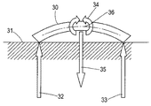
図2は、ケーシング31に衝突している根部破片30の概略断面図である。かくして、破片30の部分が点32、33のところでケーシング31と係合し、反作用が及ぼされるということに着目されたい。この際、大きな曲げモーメント34が発生する。破片30は、矢印35の方向への破片速度によるモーメントで変形する。このような場合には、破片30の部分36で公称応力が増大する。これは、荷重支持面積が減少すると同時に根部破片30のコンプライアンスが増大するためである。これによりエネルギを散逸する塑性及び亀裂が生じる。かくして、塑性で非弾性のヒンジが部分36を中心として形成され、これにより破片30を平らにでき、そのためケーシング31との接触面積を増大する。根部が湾曲している(直線状でなく)場合には、図2に示すように、点接触力が増大することは不可避である。このような場合には、破片30が大きければ大きい程、ケーシング31との衝突のエネルギが大きく、従って、裂け目(breach)ができる可能性がある。このような場合には、ケーシング31を比較的厚くし、従って、航空機のエンジンについての総重量要件を大幅に増加することが必要とされる。わかるように、重量は、航空機に関する重要な設計事項である。
FIG. 2 is a schematic sectional view of the
本発明によれば、特許請求の範囲に記載したガスタービンエンジン用ブレード、及びこのようなブレードの形成方法が提供される。 According to the present invention, a blade for a gas turbine engine and a method for forming such a blade are provided.
次に、本発明の実施例を、例として、添付図面を参照して説明する。 Embodiments of the present invention will now be described by way of example with reference to the accompanying drawings.
本発明によれば、ガスタービンエンジンで使用するためのブレードの根部区分は、一つ又はそれ以上の剪断層を含む構造を有し、そのように製造される。これらの剪断層は、一般的には、根部に楔を形成するコア内に形成される。一般的には、剪断層は、互いに関して壊れ易い部分を形成するため、隣接した材料間に配置される。代表的には、これらの剪断層は、剪断層間の分離部又はスリップ層と互いに関連した複数のセグメント又は一組のセグメントにより形成される。この分離部又はスリップ層は、一層の非接着性固体、液体又はシリコンペースト等のゲルを設けることにより形成できる。このような場合には、分離部又はスリップ層は、コアを形成する夫々の部分又は側部と側部とを向き合わせたセグメントに対して非接着性である。変形例は、張力が加わったときに砕け、粉砕され、剪断が加わる一層の低強度材料を提供することである。このような低強度材料の一例は、張力においては強力であるが剪断においては脆弱なシアノアクリレート系接着剤であってもよく、又は場合によってはアルミナ−ムライトセラミックマトリックスであってもよい。低強度接合部の別の例は、一方の表面が各セグメントに結合された閉鎖した袋形状体(バッグ)である。この袋形状体の縁部が低強度剪断接合部を形成する。コアを根部区分のキャビティ内に配置した後、全体を型成形し、通常の製造手順に従って製造を行うことができる。 In accordance with the present invention, a blade root section for use in a gas turbine engine has a structure including one or more shear layers and is so manufactured. These shear layers are typically formed in a core that forms a wedge at the root. Generally, shear layers are placed between adjacent materials to form fragile portions with respect to each other. Typically, these shear layers are formed by multiple segments or a set of segments associated with a separation or slip layer between the shear layers. This separation part or slip layer can be formed by providing a single layer of non-adhesive solid, liquid or gel such as silicon paste. In such a case, the separating part or slip layer is non-adhesive to the respective part forming the core or the segment facing the side part. A variation is to provide a much lower strength material that is crushed, crushed and sheared when tension is applied. An example of such a low strength material may be a cyanoacrylate adhesive that is strong in tension but fragile in shear, or in some cases an alumina-mullite ceramic matrix. Another example of a low strength joint is a closed bag (bag) with one surface bonded to each segment. The edge of this bag-shaped body forms a low strength shear joint. After placing the core in the cavity of the root section, the whole can be molded and manufactured according to normal manufacturing procedures.
通常の使用時に、壊れ易い部分を剪断面を通して組み合わせることにより、破砕に備えているため、ケーシングに加わる衝撃エネルギが小さくでき、従って、潜在的には比較的薄いケーシングを使用でき、特に航空機に設置する場合に重量を低減できるということは理解されよう。根部区分が、ブレードの通常の作動に対して受け入れられるものであるということが重要である、ということは理解されよう。このような場合には、一般的には、特定の平面で所定の張力荷重が加わったとき、根部区分は破砕又は滑りのみ起こることになる。かくして、閉じ込められたとき又は圧縮状態にあるとき、根部区分は頑丈であり且つコンパクトなままであり、ガスタービンエンジンのロータアッセンブリの根部区分によりブレードを保持できる。 By combining fragile parts through shearing surfaces during normal use, the impact energy applied to the casing can be reduced by preparing for crushing, so a potentially relatively thin casing can be used, especially in aircraft It will be understood that the weight can be reduced when doing so. It will be appreciated that it is important that the root section is acceptable for normal operation of the blade. In such a case, generally, when a predetermined tension load is applied in a specific plane, the root section will only break or slip. Thus, when confined or in compression, the root section remains robust and compact and the blades can be held by the root section of the gas turbine engine rotor assembly.
上述のように、一般的には、コアはキャビティ内に設けられる。コアは、上文中に説明したように、適当な形態の分離部又はスリップ層として形成された剪断層と協働したセグメントを含むことが好ましい。これらのセグメントの形態の部分は、等間隔に間隔が隔てられていてもよいし、間隔が等間隔でなくてもよく、剪断面に沿って、軸線方向に、半径方向又は周方向に、これらの軸線方向の組み合わせで、破砕するように構成されていてもよい。 As described above, generally, the core is provided in the cavity. The core preferably includes segments cooperating with a shear layer formed as a suitable form of separation or slip layer, as described above. The parts in the form of these segments may be equally spaced or may not be evenly spaced, along the shear plane, axially, radially or circumferentially. It may be configured so as to be crushed by a combination in the axial direction.
剪断層を提供するための一つの方法は、コアの部分間に隙間を形成することである。このような場合には、セグメントは、当接チーク(abutting cheeks)を含んでいてもよい。これらの当接チークは、夫々の部分又はセグメント間に空間を提供する。これらのチークは、平らであってもよいし、ドーム状をなしていてもよいし、斑点状をなしていてもよいし、ローブ状(突出状)をなしていてもよいし、簡単なスペーサによって設けられていてもよい。この場合、適当な充填材によって、部分又はセグメント間の区分を可撓性又は剛性にできる。更に、充填材は、剪断面を形成するため、部分又はセグメントの一方の面に取り付けられていてもよいし、又は両面に取り付けられていてもよい。充填材自体は、可撓性及び剪断応答に関する要件に応じて、層状をなしていてもよいし、間隔が隔てられていてもよいし、滑性であってもよいし、ガス状であってもよいし、充填されていてもよいし、充填されていなくてもよい。適当な充填材には、フォーム(発泡体)、固化しないべとべととした物質の形態の合成ペースト、フック−フリース型接合部(マジックテープ(登録商標)接合部)、又は複数の凹凸を有するれんが型接合部が含まれる。充填材は、必要に応じて、シート状であってもよいし、織製体であってもよいし、層状をなしていてもよいし、非対称であってもよい。 One way to provide a shear layer is to create a gap between the core portions. In such cases, the segments may include abutting cheeks. These abutting cheeks provide space between their respective parts or segments. These cheeks may be flat, dome-shaped, spotted, lobed (protruding), or simple spacers. May be provided. In this case, the section between the parts or segments can be made flexible or rigid by means of suitable fillers. Further, the filler may be attached to one side of the part or segment or may be attached to both sides to form a shear surface. The filler itself may be layered, spaced, slippery, or gaseous, depending on the requirements for flexibility and shear response. Alternatively, it may be filled or may not be filled. Suitable fillers include foam (foam), a synthetic paste in the form of a non-solid sticky material, a hook-fleece joint (Magic Tape (registered trademark) joint), or a brick mold with multiple irregularities. A junction is included. The filler may be in the form of a sheet, a woven material, a layer, or asymmetric as necessary.
本発明の特徴は、特に、ブレードの根部区分内にコアを形成するために楔を使用する。これらの楔コアは、非結合剪断層が取り付けられて、又は取り付けられないで提供できる。 A feature of the present invention uses a wedge to form a core in the blade root section, among others. These wedge cores can be provided with or without an unbonded shear layer.
図3に関し、コア41は、セグメント42乃至46によって形成されるということに着目されたい。これらのセグメントは、それらの間にある剪断面47乃至50で、実質的に整合しており、また、接合されている。剪断面及びブレード(図示せず)の構造部分に関し、これらのセグメント42乃至46間で様々な機構を使用できるということは理解されよう。一般的には、通常の作動状態で、ブレードを根部区分を通してロータディスク内に保持するのに十分な、圧壊抵抗を含む強度があるように、平面内の剪断面は比較的弱い。しかしながら、ブレードが外れた後のような他の条件下では、衝撃を閉じ込めるため、根部区分は曲がり、壊れて比較的小さな低エネルギのセグメントになる。これらのセグメント即ち壊れ易い部分は、実質的に、セグメント42乃至46を含み、これらのセグメントは、剪断面47乃至50のところで、セグメント42乃至46の間で、位置がずれる又は変化する(すなわち、転位)ことになる。一般的には、不連続の形態の剪断面47乃至50は、通常はブレードの下区分で、ブレード自体の内部に延びる。このような場合には、これらの転位はブレードの破壊を補助し、従って、ブレードが崩壊又は形を失った後、ブレードの重量のある区分が残らないようにする。ブレードのこれらの重量のある区分が残ると、包含ケーシングに大きなエネルギで衝突することになるからである。
Note that with respect to FIG. 3, the
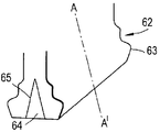
図4は、根部区分の部分51乃至54のブレード区分55、56への延長を示す。不連続部即ち剪断面57の部分が、ブレード部分55、56によって形成されている。
FIG. 4 shows the extension of the root section portions 51-54 to the
図5は、本発明による根部区分58の概略図である。図示されているように、根部区分58はキャビティ59を有し、このキャビティ59内にコア60が設けられている。本発明に従って、コア60は、剪断面を介して協働している複数の部分を有している。そのため、コア60のこれらの部分は、必要な場合、張力の作用下で優先的に破砕し又は滑るようになっている。しかしながら、図5に示すように、通常は、作動時に、根部区分58には、矢印Aが示す方向に圧縮が加わっている。この圧縮により、圧縮が加わっていない場合に生じる、コア60(即ち、根部区分58の部分)の破砕又は滑り、が阻止される。更に、製造中、根部区分58は、コアを予備圧縮するように形成でき、これにより、コア60内のセグメント間又は部分間の剪断面を中心とした脆性破壊の危険にも関わらずコアを所定位置に保持する。なお、コア60は、根部区分58の構造部分によって取り囲まれている。根部区分58は、上方にそれ自体がブレード61内に延びている。一般的には、本発明の特徴による夫々の壊れ易い表面によって形成されたセグメント又は部分の層は、根部区分58の他の部分が発生する圧壊力に耐えなければならない。
FIG. 5 is a schematic view of a
図6は、根部区分62の代表的な例を示す。この例では、根部区分62には、ロータディスクの保持部分内に配置できるように賦形部63が設けられている。上述の実施例と同様に、根部区分62の長さに沿って延びる楔形状のコア64が設けられている。このコア64は、上文中に説明したように、本発明に従って剪断面によって分離された複数の部分を含む。このような場合には、図6に示すように、コア64は根部区分62の部分を形成し、根部区分62及び関連したブレードをロータ内に保持できる。しかしながら、壊れることによって外れると、根部区分62に作用する圧縮作用又は圧壊作用が取り除かれる。一般的には、このような場合には、根部区分62は、張力が特定の平面に加えられることにより根部区分62の破砕及び崩壊が生じない限り、実質的に一体のままであり、これによりケーシングとの衝突が低衝突エネルギで行われる。
FIG. 6 shows a representative example of the
図6に示す構成の変形例では、主衝撃反作用荷重が加わる端部セグメントは、通常は圧縮応力が比較的小さい領域のブレード根部の中央の同定可能セグメントを持つ主ブレードレイアップの一体の部分であってもよい。 In the variation of the configuration shown in FIG. 6, the end segment to which the main impact reaction load is applied is usually an integral part of the main blade layup with an identifiable segment in the middle of the blade root in a region where the compressive stress is relatively low. There may be.
図7は、図6のA−A線に沿った根部区分62の変形例の断面図である。これは、図4に示す壊れ易い楔と対応する。この実施例では、コア64は、隙間又は充填材67を間に置いてキャビティ65から離間されている。本発明の幾つかの実施例では、隙間又は充填材67は、使用時に根部区分62の崩壊を助長する剪断面を提供するため、開放する。別の態様では、根部区分62が通常の作動の圧壊力及び他の圧縮力に耐えるため、隙間67は充填されていてもよい。隙間67は、壊れやすい材料で充填されていてもよく、又は上述のように、非接着性固体、液体又はゲル、又は強度が低い一層の材料又はフォーム、又は所定の平面に張力が加わった場合に破砕又は滑りを促進(急速に進行)するため、楔64と根部区分62との間に剪断面を形成するための他の手段で充填されていてもよい。
FIG. 7 is a cross-sectional view of a modification of the
図7の実施例において、隙間又は充填材67が提供する剪断面は、ブレード部分68内に上方に延びているということに着目されたい。これにより、エアロホイルブレードの破壊の開始場所を提供することによって、エアロホイルブレードの破壊を容易にする。
Note that in the embodiment of FIG. 7, the shear surface provided by the gap or
根部楔としてのコア64は、完全に破片になる必要はないが、そのようになるのが好ましいということは理解されよう。コア及び根部区分の複数の部分間に剪断面を形成することにより、張力が加わった場合に所望の平面での破砕及び滑りを急速に進行する。 It will be appreciated that the core 64 as the root wedge need not be completely debris, but it is preferable to do so. By forming shear planes between the core and root section portions, crushing and sliding in the desired plane proceeds rapidly when tension is applied.
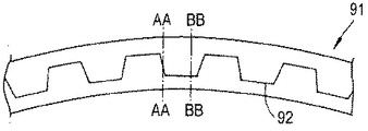
更に、根部区分を通って半径方向に延びる剪断面を提供できる。そのような半径方向に延びる剪断面を設けると、根部区分と、具体的にはこの根部区分内のコアとが、通常の使用中に分離することを防止できる。図8、図9、及び図10は、半径方向剪断面の例を例示するものである。図10は、更に、様々な位置AA−AA及びBB−BBでの、様々な剪断面位置又は半径方向の開裂(radial split)の例示を含む。これらの半径方向開裂は、図8及び図9に示す初期の半径方向剪断面に存在していてもよい。 In addition, a shear surface can be provided that extends radially through the root section. Providing such a radially extending shear surface can prevent the root section and, in particular, the core within the root section, from separating during normal use. 8, 9, and 10 illustrate examples of radial shear surfaces. FIG. 10 further includes illustrations of various shear surface locations or radial splits at various locations AA-AA and BB-BB. These radial tears may be present in the initial radial shear plane shown in FIGS.
図8には、開裂82によって半径方向剪断面が提供された根部区分コア81が示してある。開裂82は、コア81に沿って波形をなして半径方向に延びる。
FIG. 8 shows a
図9は、半径方向開裂92の形態の剪断面を含む根部区分コア91を示す。開裂92は、コア91に沿って延びる。開裂92の形態の剪断面は、ここに示すように、胸壁のような凹凸のある経路を有し、必要な場合に本発明の特徴によるコア91を組み込んだ根部区分内での破砕を急速に進行するため、特定の平面内の張力に対して所望の応答を提供する。
FIG. 9 shows a
図10は、剪断面102として作用する半径方向開裂を組み込んだ根部区分コア101を示す。剪断面102は、コア101に沿って鋸歯状経路に沿って延び、コア101の平面内での引張荷重に対して所望の応答を提供し、従って、根部区分はコア101を組み込んで用いている。
FIG. 10 shows a
図8、図9、及び図10に示す構成は、通常のガス荷重によって発生して、ブレードに作用する、軸線方向剪断に抵抗するように設計されている。軸線方向剪断は、ブレードの捩じれを取るように作用する。根部を圧壊する方向の力もまた、根部を通常の作動中に所定の場所に保持するように作用する。ブレードが外れた状態では、これらの剪断平面が自由に作動して、根部の破砕を補助する。 The configurations shown in FIGS. 8, 9, and 10 are designed to resist axial shear that is generated by normal gas loads and acts on the blade. Axial shearing acts to remove the twisting of the blade. Forces in the direction of crushing the root also act to hold the root in place during normal operation. When the blade is disengaged, these shear planes are free to operate to assist in crushing the root.
上述のように、コア81、91、101は、概ね楔形状である。このような場合には、図10に示すように、断面A−A、B−Bのところで、形成された開裂は、コア101を通って中央に延びていてもよく、又は断面BB−BBのところに示すように僅かに中央からずれていてもよい。開裂82、92、102の形態に剪断面の位置は、捩じり力に応答し、破壊が改良された態様でなされるように選択できる。この張力は、ガスタービンエンジン内の解放力によって発生し、又は図2に関して上文中に説明したように衝撃の結果として発生するということは理解されよう。
As described above, the
図8、図9、及び図10は、根部コアが通常の作動中には所定の位置にとどまるが、張力や衝撃による曲げでの破壊を補助する、根部コアに楔形態の単一の半径方向開裂を形成するのに利用可能な幾つかの選択肢の例示を提供する。 FIGS. 8, 9, and 10 show a single radial radial wedge in the root core that remains in place during normal operation, but assists in breakage in bending due to tension and impact. An illustration of several options available to form a cleavage is provided.
上述のように、一般的には、コアはブレードの根部区分のキャビティに配置される。一般的には、コアは、一層のブレード材料によって覆われている。ブレード材料の厚さは変化させてもよく、根部区分は、本質的に、コアを含み、従ってコア内に設けられた剪断面が、根部区分の破壊に関して更に直接的に作用する。コアは、代表的には、ブレードの特定の部分に接着されるが、使用時に、衝突が起った後又はブレードが外れた後、破壊を補助し且つ破壊を伝播するため、図示のように、他の位置に剪断面が設けられる。従って、上文中に説明した構成とは対照的に、水分の進入や亀裂を急速に進行する有害な凍結/解凍作用をもたらす小孔、穴、ドリルによって形成した弱め線をなくす。本発明では、剪断面が効果的に封入され(これらの剪断面が、空所によって形成されようとも、壊れ易い非接着性固体/液体又はゲル挿入体又は低強度材料層によって形成されようとも)、そのため水分の進入が阻止される。 As described above, the core is typically placed in a cavity in the root section of the blade. In general, the core is covered by a layer of blade material. The thickness of the blade material may vary and the root section essentially comprises a core, so that the shear surface provided within the core acts more directly on the root section breakage. The core is typically glued to a specific part of the blade, but in use, as shown, to assist and propagate the failure after a collision or after the blade is detached , Shearing surfaces are provided at other positions. Thus, in contrast to the configuration described above, it eliminates the weakening lines formed by small holes, holes, and drills that have a detrimental freeze / thaw action that rapidly penetrates moisture and cracks. In the present invention, shear surfaces are effectively encapsulated (whether these shear surfaces are formed by voids or by fragile non-adhesive solid / liquid or gel inserts or low strength material layers). Therefore, the ingress of moisture is blocked.
図11は、解放平面を横切るブレード111の断面図である。本発明によれば、層状分離部112の形態の剪断面が、根部区分(図示せず)から上方にブレード区分111内に延びている。わかるように、剪断面を形成する分離部は、ブレード区分111の使用時の制御下での破壊を補助する、封入された弱め線を形成する。この破壊を使用し、根部区分が多数の破片に分かれ、ブレード区分111の崩壊又は少なくとも滑りを助長し、そのため、結果的に得られた破片は個々の質量が小さく、従って、ケーシングに作用する衝突エネルギは局所的となる。これらの分離部112は、図4に示す根部延長部セグメント55、56に対する変形例である。
FIG. 11 is a cross-sectional view of the
ブレードの根部区分の夫々の部分間に剪断面を設けることにより、上文中に説明した構成と同様に、破砕が更に容易に行われ、エネルギを伝達するための局所的塑性歪が減少する。しかしながら、滑りによって塑性変形する材料の容積が増大するように設計を変更することにより、局所的塑性歪を変えずに、ケーシングへのエネルギ伝達を減少できる。剪断面の具体的な構成、位置、並びに形状は、作動上の要件に応じて変化する。これらの随意の要件は、使用された材料、作動の繰り返し、及び包含に関する必要な配慮に関する。 By providing shear planes between each portion of the root section of the blade, similar to the configuration described above, crushing is made easier and local plastic strain to transfer energy is reduced. However, energy transfer to the casing can be reduced without changing the local plastic strain by changing the design to increase the volume of the material that is plastically deformed by sliding. The specific configuration, position, and shape of the shear surface will vary depending on the operational requirements. These optional requirements relate to the materials used, repeated operation, and necessary considerations regarding inclusion.
本発明の特徴によるブレードの製造に関し、先ず最初に、本発明の特徴によるコアを収容するためのキャビティ又は他の手段を備えた根部区分を形成するということは理解されよう。上述のように、このコアは、代表的には、楔の形体をとり、又は異なる断面を持つ場合でも楔と呼ぶことができる。コアは、根部区分内に保持される。そのため、ブレードに関して続いて行われるプロセスが、上述のように、ガスタービンエンジンのロータディスク内で、根部区分形体について行われる。かくして、本発明には、完成したブレードに更に機械加工を施す必要がなく、ミスが起る機会が少なく、ミスが起こっても安価な構成要素の段階でとどまり、そのためスクラップとなったりそのための費用が遥かに小さいという特徴がある。本発明の特徴は、最初のブレード製造プロセス中に、従ってブレード製造プロセスの比較的早期の段階で、剪断面を間に形成する部分を組み込んだコアを設けることに関する。 With regard to the manufacture of a blade according to the features of the present invention, it will be understood that first of all, the root section is formed with a cavity or other means for receiving the core according to the features of the present invention. As mentioned above, this core typically takes the form of a wedge or can be referred to as a wedge even if it has a different cross-section. The core is held in the root section. Thus, subsequent processes for the blades are performed on the root segment feature in the gas turbine engine rotor disk as described above. Thus, the present invention eliminates the need for further machining of the finished blade, reduces the chances of mistakes, and stays at the low-cost component stage even if mistakes occur, thus resulting in scrap and costs Is much smaller. A feature of the present invention relates to providing a core that incorporates a portion that forms a shear surface during the initial blade manufacturing process, and thus at a relatively early stage in the blade manufacturing process.
根部区分、特に、コアやブレード区分内に延びる剪断面は、実質的ににシールされており、従って流体の進入及びこれと関連した固有の問題点がない。 The root section, in particular the shear surface extending into the core or blade section, is substantially sealed and thus free from fluid entry and the inherent problems associated therewith.
コアが設けられたブレードキャビティが本質的にシールされたままであるため、本発明の特徴に従って製造され且つ提供されたブレードに関して従来のタップ試験及び他のNDEスキャン法を使用できるということは理解されよう。 It will be appreciated that conventional tap testing and other NDE scanning methods can be used on blades manufactured and provided in accordance with features of the present invention, since the blade cavity provided with the core remains essentially sealed. .
使用時に通常の作動応力を吸収できるように、剪断層及びコアセグメントを注意深く位置決めすることによって、応力に関する懸念を解消できる。この際、衝突による特定の平面内の張力に対して根部セグメントが反作用を及ぼすが、破砕によりブレードが適切に崩壊し、又は滑りにより剪断面のところで(特に、根部区分で)エネルギが或る程度吸収される。 Careful positioning of the shear layer and core segment so that normal operating stresses can be absorbed during use can eliminate stress concerns. At this time, the root segment reacts to the tension in a specific plane due to the collision, but the blade collapses properly due to crushing, or the energy is somewhere at the shear plane (especially at the root section) due to slipping Absorbed.
本発明は、セグメントの形状、大きさ、及び位置、並びにコアの部分とブレードとの間の剪断面の位置に関して、コアを選択することにより、設計上の融通性を提供する。 The present invention provides design flexibility by selecting the core with respect to the shape, size and position of the segments and the location of the shear plane between the core portion and the blade.
ブレードは、通常の作動条件では、相対的圧縮により固定されたままであり、強固であるが、ブレードが外れる衝撃が加わった場合に破壊が生じ、剪断面のところでエネルギが吸収される。 Under normal operating conditions, the blade remains fixed by relative compression and is strong, but breakage occurs when the blade is subjected to an impact and energy is absorbed at the shear plane.
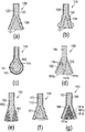
上述のように、本発明の特徴による根部区分の特定の形体は、作動上の条件で決まる。図12は、本発明の特徴による可能な根部区分形体の例を提供する。 As mentioned above, the particular shape of the root section according to the features of the present invention depends on operational conditions. FIG. 12 provides an example of possible root segment features according to features of the present invention.
図12aは、コア121がブレード120内に設けられ、金属カバー122及び基材123が複合構造をなした基本的な楔形体を示す。剪断面は、剪断面によって分離されたセグメント及び部分によって、コア121それ自体内に設けられていてもよいということは理解されよう。更に、剪断面は、コア121と基材123との間の界面124のところに形成できる。いずれにせよ、剪断面は、ブレード内に、特に根部区分内に封入されており、これによって、流体の進入が阻止される。
FIG. 12a shows a basic wedge shape in which the
図12bは、図12aに示すのと同様の形体を提供するが、わかるように、根部区分を配置するための表面形状を形成するため、金属製の外面132に縁部が設けられていることが異なっている。しかしながら、この実施例でも、基材133で形成されたブレード130内にコア131が設けられている。剪断面は、コア131内に、並びに、上文中に説明したように、コア131と基材133との間の界面134のところにも設けることができる。このような場合には、通常の使用時に、コア131は圧縮状態に保持され、従って、使用時にブレード130を保持するために加えられる圧壊力に抵抗する。しかしながら、ブレードが外れた状態では、これらの圧縮力が取り除かれ、衝突時又は特定の平面に張力が加わったとき、崩壊又は剪断滑りが生じ、その結果小さな破片が生じ、包含ケーシングとの衝突中のエネルギが小さいということは理解されよう。
FIG. 12b provides a configuration similar to that shown in FIG. 12a, but as can be seen, the metal
図12cは、液滴形体の根部区分を示す。かくしてブレード140は、金属製又は非金属製の耐蝕性カバー142によって覆われており、基材143は複合構造を有する。ブレード内、特に根部区分内にコア141が設けられている。図示のように、コア141は液滴形状であり、ブレード140内に封入されている。コア141と基材143との間の界面144に、並びにコア141それ自体の内部にも剪断面が設けられている。
FIG. 12c shows the root section of the droplet feature. Thus, the
図12dは、二つの楔が形成された別の変形例の形体を示す。かくして、ブレード区分155は、コア151a及び151bの夫々を各側部に備えている(すなわち、ブレード区分155は、コアを両側部に備えている)。根部区分を形成するため、根部カバー152(代表的には、金属製又はガラス製の構造である)が、コア151a及び151bの周囲に設けられている。このような場合には、界面154、156が、コア151a及び151bの部分間に剪断面を形成することができる。
FIG. 12d shows another variant feature in which two wedges are formed. Thus, the
図12eは別の変形例の根部区分形体を示す。コアエレメント161が、ブレード160の基材163内に挟み込まれている。ブレード160は、外部保護カバー162を有する。剪断面は、コア161と基材163との間に形成できる。コア161と基材163との間に形成された剪断面も、コア161自体の内部の任意の剪断面も、張力が加わったとき及び衝撃が加わったとき、破砕及び剪断滑りを急速に進行(促進)する。
FIG. 12e shows another variant root section feature. The
図12fは、ブレード170の根部区分の別の形体を示す。楔171の形態のコアが、ブレード170内に、詳細には、根部区分内に封入されている。かくして、コア170は、張力又は衝撃荷重の作用で破砕を急速に進行する剪断面を、部分間並びに基材173との界面に形成できる。図示のように、代表的には、ブレード170が複合構造を有するように、表面保護層172が設けられている。従って、コア171及び任意の剪断面は完全に封入されており、水分が進入する可能性がなくしてある。
FIG. 12 f shows another configuration of the root section of the
図12gは、ブレード180の根部区分についての別の形体を示す。複数の層状楔が、複数のコアエレメント181によって形成されている。コアエレメント181は複数の剪断面186を備えている。剪断面186は、コアエレメント181の間に設けられている。このような場合には、上記剪断面186と、コア181それ自体の内部に形成された剪断面と、基材183との界面184に形成された剪断面とは、張力又は衝撃荷重の作用でブレードを優先的に破砕する場所を提供し、剪断面の滑りによってエネルギを吸収する。なお、複合構造では、外保護層182が設けられことが好ましい。
FIG. 12 g shows another configuration for the root section of the
以上の実施例では、複数の剪断面を持つ複数の部分を有する根部区分を組み込んだブレードが提供される。前記複数の剪断面は、通常の使用において、即ち圧縮状態又は圧壊状態において、根部区分がブレードに対して適切に作動するように形成されている。しかしながら、特定の平面に張力が加わった場合又は自由衝撃荷重が加わった場合、剪断面がブレードの破砕を急速に進行し、従って、破片の大きさを小さくし、衝撃エネルギを小さくし、剪断面の滑りによって最初にエネルギを奪う。 In the above embodiments, a blade incorporating a root section having a plurality of portions with a plurality of shear surfaces is provided. The plurality of shear surfaces are configured so that the root section operates properly with respect to the blade in normal use, i.e. in a compressed or crushed state. However, when tension is applied to a specific plane or when a free impact load is applied, the shearing surface rapidly breaks the blade, thus reducing the size of the debris, reducing the impact energy, and reducing the shearing surface. First take away energy by sliding.
本発明の特徴の変形及び変更は、当業者に理解されるであろう。かくして、本発明の特徴によるブレードは、金属材料又は複合材料から形成されていてもよいということは理解されよう。図示のコアは、代表的には、複数の部分すなわち複数のセグメントを含み、複数の剪断面がこれらのセグメント間に適切に形成され、衝突や引張曲げ荷重の作用による優先的破砕線を形成する。このような剪断面を適当に設計し、位置及び大きさを定めることにより、引張荷重及び衝撃力に対してブレードが異なった応答をするように設計できる。本質的には、ブレード及び特に根部区分は、通常の使用時おける作動性を提供でき、しかも、必要な場合、剪断面の滑りによって優先的破砕並びにエネルギ損失を提供できる。 Variations and modifications of the features of the present invention will be understood by those skilled in the art. Thus, it will be appreciated that blades according to features of the present invention may be formed from metallic or composite materials. The illustrated core typically includes a plurality of portions or segments, and a plurality of shear surfaces are suitably formed between the segments to form a preferential fracture line due to the action of impacts and tensile bending loads. . By appropriately designing such shear surfaces and determining their location and size, the blade can be designed to respond differently to tensile loads and impact forces. In essence, the blades, and particularly the root section, can provide operability during normal use, and can provide preferential crushing as well as energy loss by slippage of the shear surface, if necessary.
41 コア
42−46 セグメント
47−50 剪断面
51−54 根部区分
55、56 ブレード区分
57 不連続部即ち剪断面部分
58 根部区分
59 キャビティ
60 コア
61 ブレード
62 根部区分
63 賦形部
64 コア
41 Core 42-46 Segment 47-50 Shear surface 51-54
Claims (15)
前記ブレードは根部区分を有し、
前記根部区分は少なくとも二つの壊れ易い部分を備え、
前記二つの壊れ易い部分は前記根部区分用のコアを形成し、
前記二つの壊れ易い部分は、これらの部分間の剪断面と組み合わさり、
これによって、前記コアは、前記根部区分の平面内に所定の張力荷重が加わった場合以外は安定した状態にとどまる、ブレード。 A blade for a gas turbine engine,
The blade has a root section;
The root section comprises at least two fragile parts;
The two fragile parts form a core for the root section;
The two fragile parts combined with a shear surface between these parts;
Thereby, the core remains in a stable state except when a predetermined tensile load is applied in the plane of the root section.
前記根部区分は、前記コアを所定の圧縮力が加わった状態に保持するように形成されている、ブレード。 The blade according to claim 1, wherein
The root section is formed to hold the core in a state where a predetermined compressive force is applied.
前記所定の圧縮力は、前記ブレードの予想作動状態に対応するように形成される、ブレード。 The blade according to claim 2, wherein
The blade is configured such that the predetermined compressive force corresponds to an expected operating state of the blade.
前記剪断面は、前記壊れ易い部分間の分離部又は滑り層によって構成される、ブレード。 The blade according to claim 1, wherein
The blade is constituted by a separation part or a sliding layer between the fragile parts.
前記分離部又は滑り層は、非接着性固体、液体、又はゲルによって形成される、ブレード。 The blade according to claim 4, wherein
The separation part or the sliding layer is a blade formed of a non-adhesive solid, liquid, or gel.
前記分離部又は滑り層は、それらの間の低強度材料によって構成され、
前記壊れ易い部分は、所定程度の張力の作用で砕け、又は粉砕され、又は剪断されるように設計されている、ブレード。 The blade according to claim 4, wherein
The separation part or the sliding layer is constituted by a low-strength material between them,
The blade, wherein the fragile part is designed to be crushed or crushed or sheared under the action of a predetermined degree of tension.
前記壊れ易い部分は、複数のセグメントによって形成されている、ブレード。 The blade according to claim 1, wherein
The fragile portion is a blade formed by a plurality of segments.
前記セグメントは、軸線方向及び/又は半径方向の所定程度の張力、及び/又は周方向滑りの作用で壊れる、ブレード。 The blade according to claim 7, wherein
The segment is broken by the action of a certain degree of axial and / or radial tension and / or circumferential slip.
これらのセグメント間の当接部分は、平らであり、又はドーム状であり、又は斑点状をなしており、又はローブ状をなしており、又はスペーサによって構成されている、ブレード。 The blade according to claim 1, wherein
The abutment between these segments is a blade that is flat, dome-shaped, spotted, lobed or constituted by spacers.
前記剪断面は、前記根部区分の所定の平面内にある、ブレード。 The blade according to claim 1, wherein
The blade is in a predetermined plane of the root section.
前記剪断面は、前記根部区分から前記ブレードのエアロホイル区分内に延びている、ブレード。 The blade according to claim 1, wherein
The blade, wherein the shear surface extends from the root section into an aerofoil section of the blade.
前記コアは、前記根部区分内で所定の予備張力荷重が加わった状態で、前記剪断面に沿った滑りによってエネルギを散逸するように形成されている、ブレード。 The blade according to claim 1, wherein
The core is configured to dissipate energy by sliding along the shear plane with a predetermined pretension load applied within the root section.
前記コアは、過度の張力荷重が前記根部区分の前記平面に加えられない限り、前記壊れ易い部分間を係合状態に保持することによって一体状態を保持する、ブレード。 The blade according to claim 1, wherein
The blade maintains an integral state by holding the fragile portion in an engaged state unless an excessive tensile load is applied to the plane of the root section.
コアを受け入れるための中空キャビティを持つ根部区分を形成する工程と、
剪断面を間に持つ少なくとも二つの壊れ易い部分でコアを形成する工程と、
前記コアを前記中空キャビティと関連させ、所定の張力荷重が前記根部区分の平面に加わった場合以外は一体状態を保持する工程とを含む、方法。 A method of forming a blade, comprising:
Forming a root section having a hollow cavity for receiving the core;
Forming a core with at least two fragile parts having a shear plane in between;
Associating the core with the hollow cavity and maintaining an integral state except when a predetermined tensile load is applied to the plane of the root section.
前記根部区分は、前記コアを所定の圧縮状態に保持するように形成されている、方法。 The method of claim 14, wherein
The method wherein the root section is configured to hold the core in a predetermined compressed state.
Applications Claiming Priority (1)
| Application Number | Priority Date | Filing Date | Title |
|---|---|---|---|
| GBGB0815482.5A GB0815482D0 (en) | 2008-08-27 | 2008-08-27 | A blade and method of making a blade |
Publications (1)
| Publication Number | Publication Date |
|---|---|
| JP2010053868A true JP2010053868A (en) | 2010-03-11 |
Family
ID=39846781
Family Applications (1)
| Application Number | Title | Priority Date | Filing Date |
|---|---|---|---|
| JP2009195780A Pending JP2010053868A (en) | 2008-08-27 | 2009-08-26 | Blade and method of making blade |
Country Status (4)
| Country | Link |
|---|---|
| US (1) | US8568082B2 (en) |
| EP (1) | EP2159373B1 (en) |
| JP (1) | JP2010053868A (en) |
| GB (1) | GB0815482D0 (en) |
Cited By (3)
| Publication number | Priority date | Publication date | Assignee | Title |
|---|---|---|---|---|
| JP2017133517A (en) * | 2011-09-14 | 2017-08-03 | ゼネラル・エレクトリック・カンパニイ | Blade and method for manufacturing blade |
| JP2018508685A (en) * | 2015-01-13 | 2018-03-29 | ゼネラル・エレクトリック・カンパニイ | Composite airfoil with fuse structure |
| US11867087B2 (en) | 2018-05-31 | 2024-01-09 | Rolls-Royce Plc | Composite fan blade root |
Families Citing this family (17)
| Publication number | Priority date | Publication date | Assignee | Title |
|---|---|---|---|---|
| GB0707426D0 (en) * | 2007-04-18 | 2007-05-23 | Rolls Royce Plc | Blade arrangement |
| GB0815475D0 (en) * | 2008-08-27 | 2008-10-01 | Rolls Royce Plc | A blade |
| GB0815482D0 (en) | 2008-08-27 | 2008-10-01 | Rolls Royce Plc | A blade and method of making a blade |
| GB0815483D0 (en) * | 2008-08-27 | 2008-10-01 | Rolls Royce Plc | Blade arrangement |
| FR2942513B1 (en) * | 2009-02-20 | 2011-05-27 | Airbus France | DAWN FOR TURBOMACHINE RECEIVER, COMPRISING A BLADE PART INCORPORATING A MECHANICAL FUSE |
| FR2963383B1 (en) * | 2010-07-27 | 2016-09-09 | Snecma | DUST OF TURBOMACHINE, ROTOR, LOW PRESSURE TURBINE AND TURBOMACHINE EQUIPPED WITH SUCH A DAWN |
| US8794925B2 (en) | 2010-08-24 | 2014-08-05 | United Technologies Corporation | Root region of a blade for a gas turbine engine |
| GB201106278D0 (en) * | 2011-04-14 | 2011-05-25 | Rolls Royce Plc | Annulus filler system |
| US9359906B2 (en) * | 2012-12-18 | 2016-06-07 | United Technologies Corporation | Rotor blade root spacer with a fracture feature |
| US9506356B2 (en) * | 2013-03-15 | 2016-11-29 | Rolls-Royce North American Technologies, Inc. | Composite retention feature |
| US10174624B1 (en) * | 2014-06-05 | 2019-01-08 | United Technologies Corporation | Composite blade root lay-up |
| EP3239469B1 (en) * | 2014-11-20 | 2019-01-09 | Rolls-Royce North American Technologies, Inc. | Composite blades for gas turbine engines |
| US9243512B1 (en) | 2015-01-14 | 2016-01-26 | General Electric Company | Rotary machine with a frangible composite blade |
| US9828862B2 (en) | 2015-01-14 | 2017-11-28 | General Electric Company | Frangible airfoil |
| US9878501B2 (en) | 2015-01-14 | 2018-01-30 | General Electric Company | Method of manufacturing a frangible blade |
| DE102015223404B4 (en) * | 2015-11-26 | 2019-01-31 | Airbus Defence and Space GmbH | Tensile test, method for producing a tensile test, apparatus for carrying out a tensile test and method for carrying out a tensile test |
| JP6778147B2 (en) * | 2017-05-31 | 2020-10-28 | 三菱重工業株式会社 | Method for manufacturing composite blades and composite blades |
Citations (3)
| Publication number | Priority date | Publication date | Assignee | Title |
|---|---|---|---|---|
| US3756745A (en) * | 1972-03-15 | 1973-09-04 | United Aircraft Corp | Composite blade root configuration |
| JPS4865507A (en) * | 1972-10-20 | 1973-09-10 | ||
| JPS59229002A (en) * | 1983-04-14 | 1984-12-22 | ゼネラル・エレクトリツク・カンパニイ | Rotary parts |
Family Cites Families (46)
| Publication number | Priority date | Publication date | Assignee | Title |
|---|---|---|---|---|
| US2362804A (en) | 1943-12-15 | 1944-11-14 | Jr Ralph Cox | Rotary wing for aircraft |
| GB723813A (en) | 1952-05-30 | 1955-02-09 | Power Jets Res & Dev Ltd | Improvements in or relating to bladed rotors for compressors, turbines and like fluid flow machines |
| US2859936A (en) | 1954-03-03 | 1958-11-11 | Cincinnati Testing & Res Lab | Compressor blade and method of forming same |
| US3057767A (en) | 1958-04-01 | 1962-10-09 | Poly Ind Inc | Method of making compressor blades |
| US3132841A (en) | 1958-05-12 | 1964-05-12 | Gen Motors Corp | Compressor blade and manufacture thereof |
| US3519368A (en) * | 1968-09-03 | 1970-07-07 | Gen Electric | Composite turbomachinery rotors |
| US3694104A (en) * | 1970-10-07 | 1972-09-26 | Garrett Corp | Turbomachinery blade |
| GB1332679A (en) | 1970-11-12 | 1973-10-03 | Gen Electric | Turbomachinery blade structure |
| US3679324A (en) | 1970-12-04 | 1972-07-25 | United Aircraft Corp | Filament reinforced gas turbine blade |
| US3744927A (en) | 1971-02-23 | 1973-07-10 | Us Navy | Yieldable blades for propellers |
| US3749518A (en) | 1972-03-15 | 1973-07-31 | United Aircraft Corp | Composite blade root configuration |
| CA1025164A (en) | 1973-09-14 | 1978-01-31 | Douglas D. Campbell | Fibrous cleansing pad enclosing a solid core of soap |
| US4040770A (en) * | 1975-12-22 | 1977-08-09 | General Electric Company | Transition reinforcement of composite blade dovetails |
| US4037990A (en) * | 1976-06-01 | 1977-07-26 | General Electric Company | Composite turbomachinery rotor |
| US4111600A (en) | 1976-12-09 | 1978-09-05 | United Technologies Corporation | Breakaway fan blade |
| US4343593A (en) | 1980-01-25 | 1982-08-10 | The United States Of America As Represented By The Secretary Of The Air Force | Composite blade for turbofan engine fan |
| GB2122691B (en) | 1982-06-17 | 1985-05-01 | Rolls Royce | Mounting of aerofoil blades |
| US4730984A (en) | 1986-09-08 | 1988-03-15 | Ortolano Ralph J | Bladed rotor structure having bifurcated blade roots |
| US5102302A (en) * | 1988-06-02 | 1992-04-07 | General Electric Company | Fan blade mount |
| US5018271A (en) | 1988-09-09 | 1991-05-28 | Airfoil Textron Inc. | Method of making a composite blade with divergent root |
| US5405102A (en) | 1990-08-03 | 1995-04-11 | Safe Flight Instrument Corporation | Foldaway aircraft air vane |
| US5160243A (en) * | 1991-01-15 | 1992-11-03 | General Electric Company | Turbine blade wear protection system with multilayer shim |
| US5176499A (en) | 1991-06-24 | 1993-01-05 | General Electric Company | Photoetched cooling slots for diffusion bonded airfoils |
| US5340280A (en) * | 1991-09-30 | 1994-08-23 | General Electric Company | Dovetail attachment for composite blade and method for making |
| US5314307A (en) * | 1992-12-18 | 1994-05-24 | Alliedsignal Inc. | Gas turbine test airfoil |
| US5443367A (en) | 1994-02-22 | 1995-08-22 | United Technologies Corporation | Hollow fan blade dovetail |
| US5490764A (en) | 1994-05-23 | 1996-02-13 | General Electric Company | Unshrouded blading for high bypass turbofan engines |
| US5584660A (en) | 1995-04-28 | 1996-12-17 | United Technologies Corporation | Increased impact resistance in hollow airfoils |
| DE19603388C1 (en) | 1996-01-31 | 1997-07-24 | Mtu Muenchen Gmbh | Device for fixing the blades on the impeller, in particular a turbine of a gas turbine engine, by riveting |
| DE19903664C2 (en) | 1999-01-29 | 2000-11-16 | Daimler Chrysler Ag | Rocket engine fueling device and heat exchanger for use in the device |
| US6431837B1 (en) | 1999-06-01 | 2002-08-13 | Alexander Velicki | Stitched composite fan blade |
| GB2360236B (en) | 2000-03-18 | 2003-05-14 | Rolls Royce Plc | A method of manufacturing an article by diffusion bonding and superplastic forming |
| GB0025012D0 (en) | 2000-10-12 | 2000-11-29 | Rolls Royce Plc | Cooling of gas turbine engine aerofoils |
| US6402469B1 (en) * | 2000-10-20 | 2002-06-11 | General Electric Company | Fan decoupling fuse |
| GB0203955D0 (en) | 2002-02-20 | 2002-04-03 | Rolls Royce Plc | A method of manufacturing an article by diffusion bonding and super[lastic forming |
| GB0216312D0 (en) * | 2002-07-12 | 2002-08-21 | Rolls Royce Plc | Frangible coupling |
| GB2391270B (en) | 2002-07-26 | 2006-03-08 | Rolls Royce Plc | Turbomachine blade |
| GB0307039D0 (en) | 2003-03-26 | 2003-04-30 | Rolls Royce Plc | A compressor blade |
| GB2401651B (en) * | 2003-05-14 | 2006-03-01 | Rolls Royce Plc | A gas turbine engine |
| GB2403987B (en) | 2003-07-11 | 2006-09-06 | Rolls Royce Plc | Blades |
| US20050158171A1 (en) | 2004-01-15 | 2005-07-21 | General Electric Company | Hybrid ceramic matrix composite turbine blades for improved processibility and performance |
| GB0522121D0 (en) * | 2005-10-29 | 2005-12-07 | Rolls Royce Plc | A blade |
| US8016561B2 (en) | 2006-07-11 | 2011-09-13 | General Electric Company | Gas turbine engine fan assembly and method for assembling to same |
| GB0614186D0 (en) * | 2006-07-18 | 2006-08-23 | Rolls Royce Plc | Blades |
| US7758311B2 (en) | 2006-10-12 | 2010-07-20 | General Electric Company | Part span shrouded fan blisk |
| GB0815482D0 (en) | 2008-08-27 | 2008-10-01 | Rolls Royce Plc | A blade and method of making a blade |
-
2008
- 2008-08-27 GB GBGB0815482.5A patent/GB0815482D0/en not_active Ceased
-
2009
- 2009-07-17 EP EP09251814.1A patent/EP2159373B1/en active Active
- 2009-08-26 JP JP2009195780A patent/JP2010053868A/en active Pending
- 2009-08-26 US US12/547,697 patent/US8568082B2/en active Active
Patent Citations (3)
| Publication number | Priority date | Publication date | Assignee | Title |
|---|---|---|---|---|
| US3756745A (en) * | 1972-03-15 | 1973-09-04 | United Aircraft Corp | Composite blade root configuration |
| JPS4865507A (en) * | 1972-10-20 | 1973-09-10 | ||
| JPS59229002A (en) * | 1983-04-14 | 1984-12-22 | ゼネラル・エレクトリツク・カンパニイ | Rotary parts |
Cited By (3)
| Publication number | Priority date | Publication date | Assignee | Title |
|---|---|---|---|---|
| JP2017133517A (en) * | 2011-09-14 | 2017-08-03 | ゼネラル・エレクトリック・カンパニイ | Blade and method for manufacturing blade |
| JP2018508685A (en) * | 2015-01-13 | 2018-03-29 | ゼネラル・エレクトリック・カンパニイ | Composite airfoil with fuse structure |
| US11867087B2 (en) | 2018-05-31 | 2024-01-09 | Rolls-Royce Plc | Composite fan blade root |
Also Published As
| Publication number | Publication date |
|---|---|
| EP2159373B1 (en) | 2017-12-27 |
| US8568082B2 (en) | 2013-10-29 |
| EP2159373A3 (en) | 2012-10-17 |
| EP2159373A2 (en) | 2010-03-03 |
| US20100054938A1 (en) | 2010-03-04 |
| GB0815482D0 (en) | 2008-10-01 |
Similar Documents
| Publication | Publication Date | Title |
|---|---|---|
| JP2010053868A (en) | Blade and method of making blade | |
| EP2159374B1 (en) | Rotor blade | |
| US8366378B2 (en) | Blade assembly | |
| US8029231B2 (en) | Fan track liner assembly | |
| JP5406528B2 (en) | Superplastically formed blade for turbine engine and manufacturing method thereof | |
| EP3034785B1 (en) | A gas turbine fan blade with varying fracture resistance | |
| US11035245B2 (en) | Fan track liner | |
| US11286782B2 (en) | Multi-material leading edge protector | |
| CN110966255B (en) | Metallic compliant tip fan blade | |
| EP2305953B1 (en) | Hollow turbine blade | |
| EP1881158B1 (en) | Blades | |
| US20120045344A1 (en) | Helicopter composite blade spar and method | |
| EP3034787A2 (en) | A gas turbine fan blade comprising a metallic leading edge having a weakened region | |
| EP1384854B1 (en) | Method and apparatus for manufacturing rotor shafts | |
| Read et al. | lI2~ United States Patent | |
| LI et al. | 65 Buckingham Gate London SW1E 6AT (GB) |
Legal Events
| Date | Code | Title | Description |
|---|---|---|---|
| A621 | Written request for application examination |
Free format text: JAPANESE INTERMEDIATE CODE: A621 Effective date: 20120821 |
|
| A131 | Notification of reasons for refusal |
Free format text: JAPANESE INTERMEDIATE CODE: A131 Effective date: 20130802 |
|
| A601 | Written request for extension of time |
Free format text: JAPANESE INTERMEDIATE CODE: A601 Effective date: 20131031 |
|
| A02 | Decision of refusal |
Free format text: JAPANESE INTERMEDIATE CODE: A02 Effective date: 20140402 |