JP2010041443A - Hollow layered structural body and waveguide structure employing hollow layered structural body, antenna, and on-vehicle radio radar - Google Patents

Hollow layered structural body and waveguide structure employing hollow layered structural body, antenna, and on-vehicle radio radar Download PDF

Info

Publication number
JP2010041443A
JP2010041443A JP2008202508A JP2008202508A JP2010041443A JP 2010041443 A JP2010041443 A JP 2010041443A JP 2008202508 A JP2008202508 A JP 2008202508A JP 2008202508 A JP2008202508 A JP 2008202508A JP 2010041443 A JP2010041443 A JP 2010041443A
Authority
JP
Japan
Prior art keywords
hollow
plate
hollow portion
laminated structure
structure according
Prior art date
Legal status (The legal status is an assumption and is not a legal conclusion. Google has not performed a legal analysis and makes no representation as to the accuracy of the status listed.)
Granted
Application number
JP2008202508A
Other languages
Japanese (ja)
Other versions
JP4672053B2 (en
Inventor
Shoji Sakai
将司 酒井
Current Assignee (The listed assignees may be inaccurate. Google has not performed a legal analysis and makes no representation or warranty as to the accuracy of the list.)
Mitsubishi Electric Corp
Original Assignee
Mitsubishi Electric Corp
Priority date (The priority date is an assumption and is not a legal conclusion. Google has not performed a legal analysis and makes no representation as to the accuracy of the date listed.)
Filing date
Publication date
Application filed by Mitsubishi Electric Corp filed Critical Mitsubishi Electric Corp
Priority to JP2008202508A priority Critical patent/JP4672053B2/en
Publication of JP2010041443A publication Critical patent/JP2010041443A/en
Application granted granted Critical
Publication of JP4672053B2 publication Critical patent/JP4672053B2/en
Expired - Fee Related legal-status Critical Current
Anticipated expiration legal-status Critical

Links

Images

Abstract

<P>PROBLEM TO BE SOLVED: To provide a hollow layered structural body in which an internal shape of each plate-like body, and positional deviation of the plate-like bodies in a vertical direction, a horizontal direction and a rotating direction can be easily confirmed even in a state where the plate-like bodies are layered. <P>SOLUTION: The hollow layered structural body 1000 is configured by layering the plurality of plate-like bodies each of which has circular first and second hollow parts 1000a1, 1000a2 for indicating shapes of circular hollow parts 1000a, 1000a. Further, when the plate-like bodies are layered, the first hollow part 1000a1 and the second hollow part 1000a2 formed on the each of plate-like bodies are formed into similar figure and configured concentrically so as to become smaller at a fixed ratio in accordance with the layering order from the top. <P>COPYRIGHT: (C)2010,JPO&INPIT

Description

この発明は、高周波信号を扱うアンテナや導波路などの分野で使用される中空積層構造体及び中空積層構造体を利用した車載用電波レーダに関するものである。   The present invention relates to a hollow laminated structure used in fields such as antennas and waveguides that handle high-frequency signals, and an in-vehicle radio wave radar using the hollow laminated structure.

近年、複数枚の板状体やブロックを積み上げることによりアンテナや導波管を構成するものが開発されている。そして複数の板状体にはそれぞれ位置合わせ用マーカが設けられ、そのマーカに基づいて板の表裏を確認しながら積層配置することにより導波管構造を形成するものであり、このように構成することにより、切削加工では困難である高精度な加工ができるため、損失をできるだけ減少させるようにするものである(特許文献1参照)。   In recent years, what constitutes an antenna or a waveguide by stacking a plurality of plates or blocks has been developed. Each of the plurality of plate-like bodies is provided with an alignment marker, and a waveguide structure is formed by laminating and arranging while checking the front and back of the plate based on the marker. Accordingly, since high-precision processing that is difficult with cutting can be performed, loss is reduced as much as possible (see Patent Document 1).

特開2003−87009号公報JP 2003-87009 A

従来の積層構造体を利用した導波管構造は、積層される複数の板状体に位置合わせ用のマーカが設けてあり、板状体の位置合わせはできる。しかし板状体を積層して構成し、各板状体の上下面が他の板状体よって覆い隠されるため、各板状体の内部形状がどのようなものであるかを判断できなくなるという問題点があった。又各板状体の上下方向、左右方向並びに回転方向の位置ずれが容易に判断できないという問題点もあった。特に、板状体を積層し、ねじ止めや接着した後で各板状体内部の加工精度並びに板状体の位置ずれを確認するときには、完成品を分解または破壊するしかないという問題点があった。   In a waveguide structure using a conventional laminated structure, alignment markers are provided on a plurality of laminated plate-like bodies, and the plate-like bodies can be aligned. However, it is configured by laminating plate-like bodies, and it is impossible to judge what the internal shape of each plate-like body is because the upper and lower surfaces of each plate-like body are covered with other plate-like bodies There was a problem. In addition, there is a problem in that it is not possible to easily determine the positional deviation of each plate-like body in the vertical direction, the horizontal direction, and the rotational direction. In particular, there is a problem that the finished product must be disassembled or destroyed when checking the processing accuracy inside the plate-like bodies and the displacement of the plate-like bodies after laminating, screwing and bonding the plate-like bodies. It was.

この発明は上記のような課題を解決するためになされたものであり、板状体を積層した状態においても各板状体内部の形状、及び各板状体の上下方向、左右方向並びに回転方向の位置ずれを容易に確認することができる中空積層構造体を提供することを目的とする。   The present invention has been made to solve the above-described problems. Even when the plate-like bodies are stacked, the shape inside each plate-like body, and the vertical direction, left-right direction, and rotation direction of each plate-like body are provided. It is an object of the present invention to provide a hollow laminated structure that can easily confirm the positional deviation.

この発明に係る中空積層構造体は、中空部を有する板状体を含む複数の板状体を積層することによって構成されるものであって、中空部を有する板状体に中空部の形状を表すためのマークを設け、マークを複数の板状体が積層されたときに他の板状体によってマークが覆い隠れない位置に形成することにより、マークが上方の積層方向一端から観察できるようにしたものである。   The hollow laminated structure according to the present invention is configured by laminating a plurality of plate-like bodies including a plate-like body having a hollow portion, and the shape of the hollow portion is formed on the plate-like body having a hollow portion. By providing a mark for display and forming the mark at a position where the mark is not covered by another plate when the multiple plates are stacked, the mark can be observed from one end in the upper stacking direction. It is a thing.

この発明に係る中空積層構造体によれば、中空部を有する板状体を含む複数の板状体を積層することによって構成されるものであって、中空部を有する板状体に中空部の形状を表すためのマークを設け、マークを複数の板状体が積層されたときに他の板状体によってマークが覆い隠れない位置に形成することにより、マークが上方の積層方向一端から観察できるようにしたので、板状体を積層した状態においても各板状体内部の形状を容易に確認することができる。   According to the hollow laminated structure according to the present invention, the hollow laminated structure is configured by laminating a plurality of plate-like bodies including a plate-like body having a hollow portion. By providing a mark to express the shape and forming the mark at a position where the mark is not covered by another plate when the multiple plates are stacked, the mark can be observed from one end in the upper stacking direction Since it did in this way, also in the state which laminated | stacked the plate-shaped object, the shape inside each plate-shaped object can be confirmed easily.

実施の形態1.
一般に導波路構造は、図1に示すように本体の外周壁に入口となる入力ポート、出口となる出力ポート等が形成される。これら入力ポート1、出力ポート2は、本体3内に穿設された導波路4a〜4cを介して連通される。本発明はこのような導波路構造を中空部を有する板状体を含む複数の板状体を積層することにより、中空積層構造体として構成したものである。
Embodiment 1 FIG.
In general, as shown in FIG. 1, in the waveguide structure, an input port serving as an inlet and an output port serving as an outlet are formed on the outer peripheral wall of the main body. The input port 1 and the output port 2 are communicated with each other through waveguides 4 a to 4 c drilled in the main body 3. In the present invention, such a waveguide structure is formed as a hollow laminated structure by laminating a plurality of plate-like bodies including a plate-like body having a hollow portion.

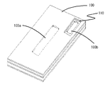
図2はこの発明の実施の形態1による中空積層構造体を示す斜視図であり、図において、中空積層構造体100は中空部を有する板状体を含む複数の板状体を積層することにより構成され、この中空部がつながることにより導波路が形成されることとなる。そして各板状体が積層されても他の板状体によって覆い隠されないように、中空部を有する板状体の外周側に突起が設けられるとともに、この突起には中抜き部が施されており、これによりマークを形成するようになっている。   FIG. 2 is a perspective view showing a hollow laminated structure according to Embodiment 1 of the present invention. In the figure, the hollow laminated structure 100 is formed by laminating a plurality of plate-like bodies including a plate-like body having a hollow portion. A waveguide is formed by connecting the hollow portions. And even if each plate-like body is laminated, a projection is provided on the outer peripheral side of the plate-like body having a hollow portion so that it is not covered with another plate-like body, and this projection has a hollow portion. Thus, a mark is formed.

図3は中空積層構造体100の一角部を示す拡大斜視図である。各板状体の積層順序は、積層方向の上から順番に第1板状体101、第2板状体102、第3板状体103、第4板状体104、第5板状体105とし、第3板状体103には中抜き部103bが形成された突起103cが設けられている。中抜き部103bの形は、第3板状体103に設けられた中空形状103aの各角部を構成する各円弧と同一半径を有する円弧によって形成される。   FIG. 3 is an enlarged perspective view showing one corner of the hollow laminated structure 100. The stacking order of each plate-like body is the first plate-like body 101, the second plate-like body 102, the third plate-like body 103, the fourth plate-like body 104, and the fifth plate-like body 105 in order from the top in the stacking direction. In addition, the third plate-like body 103 is provided with a protrusion 103c in which a hollow portion 103b is formed. The shape of the hollow portion 103 b is formed by an arc having the same radius as each arc constituting each corner of the hollow shape 103 a provided in the third plate-like body 103.

図4は第3板状体の中空部103aを示す平面図、図5は中抜き部103bを示す平面図であり、中空部103aにおける第1円弧103a1の半径と中抜き部103bにおける第1円弧103b1の半径が同一であり、第2円弧103a2の半径と第2円弧103b2の半径が同一であり、第3円弧103a3の半径と第3円弧103b3の半径が同一であり、第4円弧103a4の半径と第4円弧103b4の半径が同一である。以上のように構成することにより、各板状体が積層されても他の板状体によって覆い隠されない突起103cに設けられた中抜き部103bを確認することにより中空積層構造体の中空部103aの円弧を確認することができる。   4 is a plan view showing the hollow portion 103a of the third plate-like body, and FIG. 5 is a plan view showing the hollow portion 103b. The radius of the first arc 103a1 in the hollow portion 103a and the first arc in the hollow portion 103b. 103b1 has the same radius, the radius of the second arc 103a2 and the radius of the second arc 103b2 are the same, the radius of the third arc 103a3 and the radius of the third arc 103b3 are the same, and the radius of the fourth arc 103a4 And the radius of the fourth arc 103b4 is the same. By configuring as described above, the hollow portion 103a of the hollow laminated structure is confirmed by confirming the hollow portion 103b provided on the protrusion 103c that is not covered by another plate-like body even when the plate-like bodies are laminated. The arc can be confirmed.

上記説明においては、突起に設けられた中抜き部によりマークを形成するようにした例を示したが、図6に示すように板状体自体に中抜き部を設けてマークを形成してもよい。図6においては第3板状体103に中抜き部103bを形成した例を示しており、第1及び第2板状体に設けられた空洞部110を第3板状体103に設けられた中抜き部103bよりも大きく構成するとともに、空洞部110の内周が中抜き部103bの外周にかからないようにして、板状体の積層方向一端より中抜き部103bを観察することができるようにする必要がある。以上のように構成することにより、図2に示されたような突起が無いためハンドリングしやすくなる。   In the above description, an example in which the mark is formed by the hollow portion provided on the protrusion is shown. However, even if the mark is formed by providing the hollow portion on the plate-like body as shown in FIG. Good. FIG. 6 shows an example in which the hollow portion 103 b is formed in the third plate-like body 103, and the cavity portion 110 provided in the first and second plate-like bodies is provided in the third plate-like body 103. It is configured to be larger than the hollow portion 103b, and the hollow portion 110b can be observed from one end in the stacking direction of the plate-like body so that the inner periphery of the hollow portion 110 does not cover the outer periphery of the hollow portion 103b. There is a need to. By configuring as described above, handling is easy because there is no protrusion as shown in FIG.

上記においては、中空部を構成する円弧の径を対象にしたマークについて説明し、円弧と円弧の間の長さについては、中空部103aと中抜き部103b間において同一としなかったが、上記説明はマークの一例を示したものであり、長さも認識できるようにする場合は、例えば下記実施の形態5で説明するように、上記とは別の中抜き部を形成することとなる。上記のように本発明においては、中空部を有する板状体に中空部の形状を表すための中抜き部を設け、複数の板状体が積層されても他の板状体によって中抜き部が覆い隠れない位置に形成されることにより、中抜き部が積層方向一端から観察できるようにしたので、板状体を積層した状態においても、各板状体に設けられた中空部を容易に確認することができる。又生産工程段階においても、各板状体に設けられた中空部を容易に確認するだけで検査がし易くなるので、生産工程に費やす時間が短くなる。   In the above description, the mark for the diameter of the arc that forms the hollow portion will be described, and the length between the arc is not the same between the hollow portion 103a and the hollow portion 103b. Is an example of the mark, and when the length can be recognized, a hollow portion different from the above is formed as described in the fifth embodiment, for example. As described above, in the present invention, the plate-like body having a hollow portion is provided with a hollow portion for representing the shape of the hollow portion, and even if a plurality of plate-like bodies are stacked, the hollow portion is formed by another plate-like body. Since the hollow portion can be observed from one end in the stacking direction by being formed at a position where it does not cover and cover, the hollow portion provided in each plate-like body can be easily Can be confirmed. Even in the production process stage, it is easy to inspect by simply confirming the hollow portion provided in each plate-like body, so that the time spent in the production process is shortened.

実施の形態2.
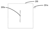
図7はこの発明の実施の形態2による中空積層構造体を構成する複数枚の板状体の中の一枚の板状体200を示す平面図である。板状体200にはスリット状の中空部200aを設けており、このスリット200aのスリット幅と同一の幅を有する突起201aを設け、この突起201aをマークとするものである。
Embodiment 2. FIG.
FIG. 7 is a plan view showing one plate-like body 200 among a plurality of plate-like bodies constituting the hollow laminated structure according to Embodiment 2 of the present invention. The plate-like body 200 is provided with a slit-like hollow portion 200a. A projection 201a having the same width as the slit width of the slit 200a is provided, and this projection 201a is used as a mark.

図8は突起201aを示す平面拡大図であり、板状体200に設けられたスリット状の中空部200aと同一の幅201a1を有する突起201aを板状体200の外周に設けたものである。以上のように構成することにより、各板状体が積層されても他の板状体によって覆い隠されない突起201aの幅201a1を測定することにより、板状体200に設けられたスリット状の中空形状200aのスリット幅を確認できる。   FIG. 8 is an enlarged plan view showing the protrusion 201 a, in which a protrusion 201 a having the same width 201 a 1 as the slit-shaped hollow portion 200 a provided on the plate-like body 200 is provided on the outer periphery of the plate-like body 200. By configuring as described above, the slit-like hollow provided in the plate-like body 200 is measured by measuring the width 201a1 of the protrusion 201a that is not covered by the other plate-like bodies even if each plate-like body is laminated. The slit width of the shape 200a can be confirmed.

実施の形態3.
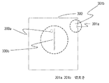
図9はこの発明の実施の形態3による中空積層構造体を構成する複数枚の板状体の中の一枚の中空部を有する板状体300を示す平面図である。板状体300には円形の中空部300aとスリット状の中空部300bが設けられており、更に板状体300の外周部には円弧状の切欠き301aとスリット状の切欠き301bを設け、これによりマークを構成したものである。図10は板状体300の外周部を示す拡大平面図であり、円形の中空部300aの半径と同一の半径301a1を有する円弧状の切欠き301aと、スリット状の中空部300bの幅と同一の幅301b1を有するスリット状の切欠き301bを設けている。そして板状体300が第3板状体のような場合には、第1及び第2板状体の切欠き301a、301bに対応する位置に、切欠き301a、301bよりも大きな切欠きを設けることにより、積層方向一端から切欠き301a、301bが観察できるようにするものである。
Embodiment 3 FIG.
FIG. 9 is a plan view showing a plate-like body 300 having one hollow portion among a plurality of plate-like bodies constituting a hollow laminated structure according to Embodiment 3 of the present invention. The plate-like body 300 is provided with a circular hollow portion 300a and a slit-like hollow portion 300b, and an arc-shaped notch 301a and a slit-like notch 301b are provided on the outer periphery of the plate-like body 300, This constitutes a mark. FIG. 10 is an enlarged plan view showing the outer peripheral portion of the plate-like body 300. The arc-shaped notch 301a having the same radius 301a1 as the radius of the circular hollow portion 300a and the width of the slit-shaped hollow portion 300b are the same. A slit-shaped notch 301b having a width 301b1 is provided. When the plate-like body 300 is a third plate-like body, notches larger than the notches 301a and 301b are provided at positions corresponding to the notches 301a and 301b of the first and second plate-like bodies. Thus, the notches 301a and 301b can be observed from one end in the stacking direction.

以上のように構成することにより、各板状体が積層されても他の板状体によって覆い隠されない円形の切欠き301aの径301a1及びスリット状の切欠き301bの幅301b1を測定することにより、板状体300に設けられた中空部300aの径と中空部300bの幅を確認できる。またマークとして切欠きを採用しており、突起が無いためハンドリングしやすい。   By configuring as described above, by measuring the diameter 301a1 of the circular notch 301a and the width 301b1 of the slit-like notch 301b which are not covered by other plate-like bodies even when the respective plate-like bodies are stacked. The diameter of the hollow part 300a provided in the plate-like body 300 and the width of the hollow part 300b can be confirmed. In addition, a notch is used as a mark, and it is easy to handle because there is no protrusion.

実施の形態4.
図11はこの発明の実施の形態4による中空積層構造体を構成する複数枚の板状体の中の一枚の板状体400を示す平面図である。板状体400にはL字型の中空部400aが設けられており、この中空部400aを構成するスリット幅、円弧、角度と同一寸法を有するL字型の中抜き部401aを設け、これによりマークを構成したものである。
Embodiment 4 FIG.
FIG. 11 is a plan view showing one plate-like body 400 among a plurality of plate-like bodies constituting a hollow laminated structure according to Embodiment 4 of the present invention. The plate-like body 400 is provided with an L-shaped hollow portion 400a, and an L-shaped hollow portion 401a having the same dimensions as the slit width, arc, and angle constituting the hollow portion 400a is provided. The mark is composed.

図12は中抜き部401aを示す平面拡大図であり、板状体400に設けられた中空部400aを構成するL字型のスリットのスリット幅と同一のスリット幅を中抜き部401aのスリット幅401a1とし、中空部400aを構成する内側円弧の径と同一の径を中抜き部401aの内側円弧径401a2とし、中空部400aを構成する外側円弧の径と同一の径を中抜き部401aの外側円弧径401a3とし、中空部400aを構成する終端円弧の径と同一の径を中抜き部401aの終端円弧径401a4とし、更に中空部400aのL字型を構成する角度と同一の角度を中抜き部401aのL字型を構成する角度401a5とする。そして板状体400が第3板状体のような場合には、例えば図6に示すように、第1及び第2板状体に中抜き形状401aよりも大きな空洞部を設け、複数の板状体が積層されても他の板状体により中抜き部401aが覆い隠されないようにすることができる。又図2に示すように突起を設け、この突起に中抜き部401aを設けるようにしても良い。   FIG. 12 is an enlarged plan view showing the hollow portion 401a. The slit width of the hollow portion 401a is equal to the slit width of the L-shaped slit constituting the hollow portion 400a provided in the plate-like body 400. FIG. 401a1, the same diameter as the diameter of the inner arc constituting the hollow portion 400a is set as the inner arc diameter 401a2 of the hollow portion 401a, and the same diameter as the outer arc diameter constituting the hollow portion 400a is set outside the hollow portion 401a. The arc diameter 401a3 is the same as the diameter of the terminal arc constituting the hollow portion 400a, the terminal arc diameter 401a4 of the hollow portion 401a, and the same angle as the angle forming the L-shape of the hollow portion 400a is hollowed out. The angle 401a5 that constitutes the L-shape of the portion 401a is used. When the plate-like body 400 is a third plate-like body, for example, as shown in FIG. 6, the first and second plate-like bodies are provided with a cavity portion larger than the hollow shape 401a, and a plurality of plates It is possible to prevent the hollow portion 401a from being covered with another plate-like body even if the like bodies are stacked. Further, as shown in FIG. 2, a protrusion may be provided, and a hollow portion 401a may be provided on the protrusion.

以上のように構成することにより、各板状体が積層されても他の板状体によって覆い隠されないスリット幅401a1,円弧径401a2、401a3、401a4、及び角度401a5を測定することにより、板状体400に設けられたL字型の中空部400aのスリット幅、内側円弧径、外側円弧径、終端円弧径及びL字型を構成する角度を確認できる。また、マークとして板状体自体に中抜き部を形成しており、突起が無いためハンドリングしやすい。   By configuring as described above, by measuring the slit width 401a1, the arc diameters 401a2, 401a3, 401a4, and the angle 401a5 that are not covered by other plate-like bodies even if the respective plate-like bodies are laminated, The slit width, the inner arc diameter, the outer arc diameter, the terminal arc diameter, and the angle forming the L shape of the L-shaped hollow portion 400a provided in the body 400 can be confirmed. Further, a hollow portion is formed as a mark in the plate-like body itself, and since there is no projection, it is easy to handle.

実施の形態5.
図13はこの発明の実施の形態5による中空積層構造体を構成する複数枚の板状体の中の一枚の板状体500を示す平面図である。本実施形態においては、板状体500に突起501bを設けるとともに、この突起501bに板状体500に設けられた中空部500aと同一の形状である中抜き部501aを設け、これをマークとしたものである。図14は中抜き部501aを示す平面拡大図であり、板状体500に設けられた中空部500aと同一の形状となっている。
Embodiment 5 FIG.
FIG. 13 is a plan view showing one plate-like body 500 among a plurality of plate-like bodies constituting a hollow laminated structure according to Embodiment 5 of the present invention. In the present embodiment, the plate-like body 500 is provided with a protrusion 501b, and the protrusion 501b is provided with a hollow portion 501a having the same shape as the hollow portion 500a provided in the plate-like body 500, which is used as a mark. Is. FIG. 14 is an enlarged plan view showing the hollow portion 501 a and has the same shape as the hollow portion 500 a provided in the plate-like body 500.

以上のように構成することにより、各板状体が積層されても他の板状体によって覆い隠されない中抜き部501aを測定することにより、中空積層構造体を構成する中空部500aの形状を確認できる。更には中抜き部501aは中空部500aと同一の形状であるため、性能をも推定することができる。   By configuring as described above, the shape of the hollow portion 500a constituting the hollow laminated structure can be obtained by measuring the hollow portion 501a that is not covered by another plate-like body even when the plate-like bodies are laminated. I can confirm. Furthermore, since the hollow portion 501a has the same shape as the hollow portion 500a, the performance can be estimated.

実施の形態6.
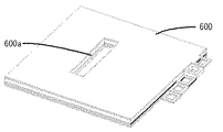
図15はこの発明の実施の形態6による中空積層構造体600を示す斜視図であり、本実施形態においては、中空積層構造体600を構成する各板状体の一側面に突起を設けるとともに、各突起には各板状体に設けられた中空部と同一の形状を有する中抜き部を設け、更に各突起を所定の間隔でずらして設けたものである。
Embodiment 6 FIG.
FIG. 15 is a perspective view showing a hollow laminated structure 600 according to Embodiment 6 of the present invention. In this embodiment, a protrusion is provided on one side surface of each plate-like body constituting the hollow laminated structure 600, and FIG. Each protrusion is provided with a hollow portion having the same shape as the hollow portion provided in each plate-like body, and each protrusion is provided with a predetermined interval.

図16は中空積層構造体600の一側面部を示す拡大斜視図であり、各板状体の同一側面部であって、第1板状体601に第1突起601a、第2板状体602に第2突起602a、第3板状体603に第3突起603a、第4板状体604に第4突起604a、第5板状体605に第5突起605aがそれぞれ設けられており、各突起には各板状体に設けられた中空部と同一の形状を有する中抜き部が設けられている。   FIG. 16 is an enlarged perspective view showing one side surface portion of the hollow laminated structure 600, which is the same side surface portion of each plate-like body, and includes a first projection 601 a and a second plate-like body 602. Are provided with a second projection 602a, a third projection 603a on the third plate 603, a fourth projection 604a on the fourth plate 604, and a fifth projection 605a on the fifth plate 605. Is provided with a hollow portion having the same shape as the hollow portion provided in each plate-like body.

また、第1突起601aの側面方向に沿う長さ601b、第2突起602aの長さ602b、第3突起603aの長さ603b、第4突起604aの長さ604b、第5突起605aの長さ605bはそれぞれ同一であり、例えば10mmにすることができる。   Further, the length 601b along the side surface direction of the first protrusion 601a, the length 602b of the second protrusion 602a, the length 603b of the third protrusion 603a, the length 604b of the fourth protrusion 604a, and the length 605b of the fifth protrusion 605a. Are the same, for example, 10 mm.

第2突起602aの位置は、第1突起601aの位置に対して、側面の長手方向(図16のA方向)において第1突起601aの長さ601b(10mm)分だけずれた位置にあり、第3突起603aの位置は第2突起602aを基準にして第1突起601aがある位置とは反対方向であって、第2突起602aの位置に対して、A方向において第2突起602aの長さ602b(10mm)分だけずれた位置にあり、第4突起604aの位置は第3突起603aを基準にして第2突起602aがある位置とは反対方向であって、第3突起603aの位置に対して、A方向において第3突起603aの長さ603b(10mm)分だけずれた位置にあり、第5突起605aの位置は第4突起604aを基準にして第3突起603aがある位置とは反対方向であって、第4突起604aの位置に対して、A方向において第4突起604aの長さ604b(10mm)分だけずれた位置にある。即ち各板状体を積層したときに各突起601a〜605aが積層方向一端の板状体から順番に階段状に並ぶように配列されている。   The position of the second protrusion 602a is shifted from the position of the first protrusion 601a by the length 601b (10 mm) of the first protrusion 601a in the longitudinal direction of the side surface (direction A in FIG. 16). The position of the third protrusion 603a is opposite to the position where the first protrusion 601a is located with respect to the second protrusion 602a, and the length 602b of the second protrusion 602a in the A direction with respect to the position of the second protrusion 602a. The position of the fourth protrusion 604a is opposite to the position of the second protrusion 602a with respect to the position of the third protrusion 603a, with respect to the position of the third protrusion 603a. The third protrusion 603a is displaced by a length 603b (10 mm) in the A direction, and the position of the fifth protrusion 605a is the position where the third protrusion 603a is located with reference to the fourth protrusion 604a. Is a direction opposite, with respect to the position of the fourth projection 604a, is in a position shifted by a length 604b (10 mm) fraction of the fourth projection 604a in the A direction. That is, when the plate-like bodies are stacked, the protrusions 601a to 605a are arranged in a stepped manner in order from the plate-like body at one end in the stacking direction.

以上のように構成することにより、各板状体が積層されても他の板状体によって覆い隠されない突起に設けられた中抜き部を測定することにより、中空積層構造体の中空部600aを確認することができるだけでなく、更に積層順序が間違っていれば各突起が階段状に並ばないので、積層順序の間違いも確認できる。   By configuring as described above, the hollow portion 600a of the hollow laminated structure can be obtained by measuring the hollow portion provided in the protrusion that is not covered by the other plate-like bodies even when the respective plate-like bodies are laminated. Not only can it be confirmed, but if the stacking order is wrong, the protrusions will not line up in a staircase pattern, so an error in the stacking order can be confirmed.

図17は別の形態による中空積層構造体610を示す斜視図であり、第2〜第5板状体において中抜き部を設けるとともに、これらの中抜き部が図16に示すものと同様に階段状になるように構成したものである。この場合には第1板状体には中空積層構造体の中空部と同一形状を有する中抜き部は構成されないが、第2〜第5板状体の中抜き部を覆い隠さないような空洞部を有している。図17に示すような構成であれば、図16に示すような突起を有さないので、ハンドリングがし易くなる。   FIG. 17 is a perspective view showing a hollow laminated structure 610 according to another embodiment. In the second to fifth plate-like bodies, hollow portions are provided, and these hollow portions are stepped similarly to those shown in FIG. It is comprised so that it may become a shape. In this case, the first plate-like body does not have a hollow portion having the same shape as the hollow portion of the hollow laminated structure, but does not cover the hollow portions of the second to fifth plate-like bodies. Has a part. With the configuration as shown in FIG. 17, since there is no protrusion as shown in FIG. 16, handling becomes easy.

実施の形態7.
図18はこの発明の実施の形態7による中空積層構造体700を示す斜視図であり、本実施形態においては、各板状体に設けられた中抜き部の大きさを各板状体毎に異なるように構成し、各板状体が積層されたときに上下に隣接する一方(上方)の中抜き部がもう一方(下方)の中抜き部よりも大きくなるようにして、中抜き部が階段状になるように構成したものである。図18の場合、中空積層構造体に設けられた中空部700aは長方形に構成されており、各板状体に設けられた中抜き部は、中空積層構造体の中空部700aを確認することができるように長方形に構成される。
Embodiment 7 FIG.
FIG. 18 is a perspective view showing a hollow laminated structure 700 according to Embodiment 7 of the present invention. In this embodiment, the size of the hollow portion provided in each plate-like body is set for each plate-like body. It is configured differently so that when each plate-like body is stacked, one (upper) hollow portion adjacent vertically is larger than the other (lower) hollow portion so that the hollow portion is It is configured to be stepped. In the case of FIG. 18, the hollow part 700a provided in the hollow laminated structure is configured in a rectangular shape, and the hollow part provided in each plate-like body confirms the hollow part 700a of the hollow laminated structure. Configured in a rectangle so that it can.

図19はマークとなる中抜き部を示す平面拡大図であり、第1板状体701に第1中抜き部701aを構成し、第1中抜き部701aの外周より内側に位置するように第2板状体702の第2中抜き部702aを構成し、第2中抜き部702aの外周より内側に位置するように第3板状体703の第3中抜き部703aを構成し、第3中抜き部703aの外周より内側に位置するように第4板状体704の第4中抜き部704aを構成し、第4中抜き部704aの外周より内側に位置するように第5板状体705の第5中抜き部705aを構成している。即ち各板状体を積層したときに中抜き部701a〜705aが階段状に並ぶように構成される。   FIG. 19 is an enlarged plan view showing a hollow portion serving as a mark. The first hollow plate portion 701 includes a first hollow portion 701a and is located on the inner side of the outer periphery of the first hollow portion 701a. A second hollow portion 702a of the two plate-like body 702 is formed, and a third hollow portion 703a of the third plate-like body 703 is formed so as to be located inside the outer periphery of the second hollow portion 702a. The fourth plate-like body 704 is configured so as to be located inside the outer periphery of the hollow portion 703a, and the fifth plate-like body is located inside the outer periphery of the fourth hollow portion 704a. A fifth hollow portion 705a of 705 is configured. That is, the hollow portions 701a to 705a are arranged in a step shape when the plate-like bodies are stacked.

上記のように中抜き部を板状体の積層方向一端から順番に小さくなるように構成して、各板状体が積層されても他の板状体によって覆い隠されない中抜き部を測定することにより、中空積層構造体の中空部700a全ての形状を確認できる。また、中抜き部によってマークを構成しており、突起が無いためハンドリングしやすい。   As described above, the hollow portion is configured to become smaller in order from one end in the stacking direction of the plate-like bodies, and the hollow portion that is not covered by the other plate-like bodies is measured even if the plate-like bodies are laminated. Thus, the shape of all the hollow portions 700a of the hollow laminated structure can be confirmed. Further, the mark is constituted by the hollow portion, and since there is no protrusion, it is easy to handle.

実施の形態8.
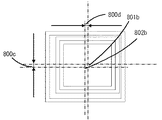
図20はこの発明の実施の形態8による中空積層構造体800を示す斜視図であり、本実施形態においては、実施の形態7の場合と同様、中抜き部が階段状になるよう構成され、各板状体が積層されたときに上からの積層順に従って順番に中抜き部が一定の割合で小さくなるような相似形に形成されるとともに、中抜き部の重心位置が各板状体間において一致するように構成したものである。
Embodiment 8 FIG.
FIG. 20 is a perspective view showing a hollow laminated structure 800 according to the eighth embodiment of the present invention. In this embodiment, the hollow portion is configured to be stepped like the seventh embodiment, When each plate-like body is laminated, it is formed in a similar shape so that the hollow portion becomes smaller at a certain rate in order according to the stacking order from the top, and the center of gravity position of the hollow portion is between each plate-like body In FIG.

図21、図22は中空積層構造体800における中抜き部を示す平面拡大図であり、図21は正しく積層されている状態を示すとともに、図22は積層位置がずれている状態を示している。上記実施の形態7の場合と同様、第1板状体801に第1中抜き部801aを構成し、第1中抜き部801aの外周より内側に第2板状体802の第2中抜き部802aを構成し、第2中抜き部802aの外周より内側に第3板状体803の第3中抜き部803aを構成し、第3中抜き部803aの外周より内側に第4板状体804の第4中抜き部804aを構成し、第4中抜き部804aの外周より内側に第5板状体805の第5中抜き部805aを構成している。即ち各板状体を積層したときに各板状体の中抜き部が階段状に並ぶように構成される。   21 and 22 are enlarged plan views showing hollow portions in the hollow laminated structure 800. FIG. 21 shows a state in which the layers are correctly laminated, and FIG. 22 shows a state in which the lamination positions are shifted. . Similar to the case of the seventh embodiment, the first plate-like body 801 is configured with the first hollow portion 801a, and the second hollow portion of the second plate-like body 802 is located on the inner side of the outer periphery of the first hollow portion 801a. 802a is configured, a third hollow portion 803a of the third plate-like body 803 is formed inside the outer periphery of the second hollow portion 802a, and a fourth plate-like body 804 is formed inside the outer periphery of the third hollow portion 803a. 4th hollow part 804a is comprised, and the 5th hollow part 805a of the 5th plate-shaped body 805 is comprised inside the outer periphery of the 4th hollow part 804a. That is, when the plate-like bodies are stacked, the hollow portions of the plate-like bodies are arranged in a staircase pattern.

図21において、中空積層構造体800の中抜き部重心位置800bは上方向から見たときに一致しており、中抜き部の大きさは板状体の積層順番に応じて一定の割合で小さくなるような相似形に形成されており、例えば積層順に中抜き部の縦横の幅を1mmずつ小さくなるように構成する。従って各板状体の位置ずれがなければ図21に示すように、中抜き部の重心位置800bが一致した階段状を形成するように構成される。   In FIG. 21, the center of gravity position 800 b of the hollow portion of the hollow laminated structure 800 coincides when viewed from above, and the size of the hollow portion is reduced at a certain rate according to the stacking order of the plate-like bodies. For example, the vertical and horizontal widths of the hollow portions are reduced by 1 mm in order of stacking. Therefore, if there is no position shift of each plate-like body, as shown in FIG. 21, a staircase shape in which the center of gravity position 800b of the hollow portion coincides is formed.

図22に示すように、積層位置がずれると中抜き部が図21に示すように階段状に並ばなくなる。図21においては、第2板状体802がずれている状態を示している。この場合第1中抜き部801aの重心位置801bと第2中抜き部802aの重心位置802bのずれ量である縦位置ずれ長さ800cと横位置ずれ長さ800dを測定することにより位置ずれ量が確認できる。   As shown in FIG. 22, when the stacking position is shifted, the hollow portions are not lined up stepwise as shown in FIG. FIG. 21 shows a state where the second plate-like body 802 is displaced. In this case, the amount of misalignment can be determined by measuring the longitudinal misalignment length 800c and the lateral misalignment length 800d, which are misalignments between the center of gravity position 801b of the first hollow portion 801a and the gravity center position 802b of the second hollow portion 802a. I can confirm.

上記のように積層方向一端から順番に中抜き部を一定の割合で小さくなるような相似形で構成することにより、各板状体が積層されても他の板状体によって覆い隠されない中抜き部を測定することにより、中空積層構造体の中空部800a全ての形状を確認できるだけでなく、重心位置を中心とした位置からの積層位置のずれも確認することができる。   As described above, the hollow portions that are not covered by other plate-like bodies even if they are laminated by configuring the hollow portions in order from one end in the stacking direction so as to become smaller at a constant rate. By measuring the portion, not only the shape of all the hollow portions 800a of the hollow laminated structure can be confirmed, but also the deviation of the laminated position from the position centered on the center of gravity can be confirmed.

実施の形態9.
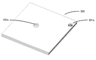
図23はこの発明の実施の形態9による中空積層構造体900を示す斜視図であり、本実施形態においては、中空積層構造体900の中空部900a及び中抜き部901aを円形に構成したものである。更に各板状体が積層されたときに各板状体に形成された中抜き部は上からの積層順に応じて一定の割合で小さくなるような相似形で形成されるとともに、同心円上に構成される。
Embodiment 9 FIG.
FIG. 23 is a perspective view showing a hollow laminated structure 900 according to Embodiment 9 of the present invention. In this embodiment, the hollow portion 900a and the hollow portion 901a of the hollow laminated structure 900 are formed in a circular shape. is there. Furthermore, when each plate-like body is laminated, the hollow portion formed in each plate-like body is formed in a similar shape so as to be reduced at a certain rate according to the order of lamination from above, and is configured on a concentric circle. Is done.

このように構成することにより、各板状体が積層されても他の板状体によって覆い隠されない中抜き部を測定することにより、中空積層構造体の中空部900a全ての形状を確認できるだけでなく、重心位置を中心とした位置からの積層位置ずれも確認することができる。また、中抜き部を組立時の基準穴としても利用できる。   By configuring in this way, it is only possible to confirm the shape of all the hollow portions 900a of the hollow laminated structure by measuring the hollow portions that are not covered by other plate-like bodies even if the respective plate-like bodies are laminated. In addition, it is also possible to confirm the stacking position deviation from the position centered on the center of gravity position. Further, the hollow portion can be used as a reference hole during assembly.

実施の形態10.
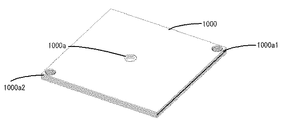
図24はこの発明の実施の形態10による中空積層構造体1000を示す斜視図であり、実施の形態9で示した中抜き部と同じものを各板状体に2個設けたものである。図において、中空積層構造体1000には中空部1000a、第1中抜き部1000a1、第2中抜き部1000a2が設けられている。
Embodiment 10 FIG.
FIG. 24 is a perspective view showing a hollow laminated structure 1000 according to the tenth embodiment of the present invention, in which two same hollow parts as those shown in the ninth embodiment are provided in each plate-like body. In the figure, the hollow laminated structure 1000 is provided with a hollow portion 1000a, a first hollow portion 1000a1, and a second hollow portion 1000a2.

図25は中空積層構造体1000を示す平面図であり、各板状体の積層位置が正しい状態を示している。この場合には、各板状体に設けられた中抜き部の重心位置が重なり、重心位置を中心とした階段状となるため、第1中抜き部1000a1と第2中抜き部1000a2の重心位置を線で結ぶと1本の直線となる。   FIG. 25 is a plan view showing the hollow laminated structure 1000 and shows a state where the lamination positions of the plate-like bodies are correct. In this case, the center of gravity positions of the hollow portions provided in the respective plate-like bodies are overlapped to form a step shape centered on the barycentric position. Therefore, the gravity center positions of the first hollow portion 1000a1 and the second hollow portion 1000a2. When the lines are connected by a line, a straight line is obtained.

図26は中空積層構造体1000を示す平面図、図27は一方の中抜き部を示す平面拡大図であり、積層位置がずれている状態を示している。積層位置が正しくないと2個所の第1中抜き部1000a1と第2中抜き部1000a2のうち少なくとも1個所の中抜き形状が同心円の階段状に並ばなくなり、第1重心線1001cと第2重心線1002cに分かれる。第1重心位置1001bと第2重心位置1002bの縦位置ずれ長さ1000bと横位置ずれ長さ1000cと位置ずれ角度1000dを測定することにより位置ずれ量を確認する事ができる。   FIG. 26 is a plan view showing the hollow laminated structure 1000, and FIG. 27 is an enlarged plan view showing one hollow portion, showing a state where the lamination positions are shifted. If the stacking position is not correct, at least one of the two first hollow portions 1000a1 and 1000a2 is not aligned in a concentric stepped shape, and the first centroid line 1001c and the second centroid line. It is divided into 1002c. The amount of displacement can be confirmed by measuring the longitudinal displacement length 1000b, the lateral displacement length 1000c, and the displacement angle 1000d of the first gravity center position 1001b and the second gravity center position 1002b.

この構成により、各板状体が積層されても他の板状体によって覆い隠されない中抜き形状を測定することにより、中空積層構造体の中空形状1000a全ての形状を確認できるだけでなく、2個所の中抜き形状の重心位置を測定することにより積層位置のずれも確認できる。また、第1中抜き部1000a1、第2中抜き部1000a2を組立時の基準穴としても利用できる。   With this configuration, by measuring the hollow shape that is not covered by other plate-like bodies even if each plate-like body is laminated, not only the shape of all the hollow shapes 1000a of the hollow laminated structure can be confirmed, but two places By measuring the position of the center of gravity of the hollow shape, it is possible to confirm the deviation of the stacking position. Further, the first hollow portion 1000a1 and the second hollow portion 1000a2 can also be used as reference holes during assembly.

尚図24〜図27においては、第1中抜き部1000a1及び第2中抜き部1000a2を対角線上に設けるようにしたが、2つの中抜き部は他の配置関係になるように配置してもよい。更に中抜き部を3つ以上の複数個設けるようにしてもよい。   In FIGS. 24 to 27, the first hollow portion 1000a1 and the second hollow portion 1000a2 are provided on a diagonal line, but the two hollow portions may be arranged to have other arrangement relationships. Good. Further, a plurality of three or more hollow portions may be provided.

実施の形態11.
上記実施の形態1〜10に記載の中空積層構造体を構成する板状体に設けられた中空部、中抜き部、切欠き、突起はプリント基板の配線形成などに用いられているエッチング工程により形成することができる。切削加工により中空部、中抜き部等を形成すると、削りかすが生じてしまうので、板状体を積層する時に削りかすが邪魔になり、精度良く板状体を積層することができなくなるが、エッチングで形成するとこのような削りかすは生じないので、精度良く積層することができる。又エッチングで形成すると、切削加工に比べて正確に所望の中空部、中抜き部等を形成することができる。
Embodiment 11 FIG.
The hollow part, the hollow part, the notch, and the protrusion provided on the plate-like body constituting the hollow laminated structure described in the first to tenth embodiments are formed by an etching process used for wiring formation of a printed circuit board. Can be formed. If hollow parts, hollow parts, etc. are formed by cutting, scraping will occur, so when scraping the plate, the scraping will be in the way and it will not be possible to stack the plate with high precision. When formed, such shavings do not occur, so that the layers can be accurately laminated. Further, when formed by etching, a desired hollow portion, hollow portion, etc. can be formed more accurately than cutting.

実施の形態12.
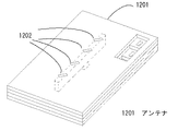
本実施形態においては、上記実施の形態1〜11で示した中空形状を有する板状体を含む複数の板状体を積層することによって構成される中空積層構造体をアンテナ1201として利用したものであり、図28はこの発明の実施の形態12による中空積層構造体を示す斜視図、図29は平面図、図30は図29におけるX−X線断面図である。
Embodiment 12 FIG.
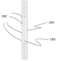
In this embodiment, a hollow laminated structure configured by laminating a plurality of plate-like bodies including the plate-like body having the hollow shape shown in the above-described first to eleventh embodiments is used as the antenna 1201. FIG. 28 is a perspective view showing a hollow laminated structure according to Embodiment 12 of the present invention, FIG. 29 is a plan view, and FIG. 30 is a sectional view taken along line XX in FIG.

図において、一番上に載置された板状体に設けられた中空部がアンテナ部1202であり、内部に導波路1203が形成されている。更に一番下に載置された板状体には入出力ポート1204が形成されている。入出力ポート1204から出力された信号は導波路1203を通過してアンテナ部1202から発信され、更にアンテナ部1202から入力された信号は導波路1203を通過して入出力ポート1204に入力される。   In the figure, the hollow portion provided in the plate-like body placed on the top is an antenna portion 1202, and a waveguide 1203 is formed inside. Further, an input / output port 1204 is formed on the plate-like body placed at the bottom. A signal output from the input / output port 1204 is transmitted from the antenna unit 1202 through the waveguide 1203, and a signal input from the antenna unit 1202 is input to the input / output port 1204 through the waveguide 1203.

実施の形態13.
本実施形態においては、上記実施の形態1〜11で示した中空積層構造体を使用して車載用電波レーダを構成したものである。図31はこの発明の実施の形態13による車載用電波レーダを示す斜視図、図32は断面側面図である。図において、車載用電波レーダ1301はフロントカバー1302とケース1303からなり、これらフロントカバー1302とケース1303の内部に実施の形態1〜11で示した中空積層構造体1304が内臓されている。
Embodiment 13 FIG.
In the present embodiment, an in-vehicle radio wave radar is configured using the hollow laminated structure shown in the first to eleventh embodiments. FIG. 31 is a perspective view showing an in-vehicle radio wave radar according to Embodiment 13 of the present invention, and FIG. 32 is a sectional side view. In the figure, an on-vehicle radio wave radar 1301 includes a front cover 1302 and a case 1303, and the hollow laminated structure 1304 shown in the first to eleventh embodiments is incorporated in the front cover 1302 and the case 1303.

そして一番上の板状体に設けられた中空部がアンテナ部1305を形成し、更には内部に導波路1306が形成され、一番下部には車載用電波レーダを制御するための制御基板1307が載置されている。制御基板1307から出力された電波は導波路1306を伝搬し、アンテナ部1305から放射される。また、外部からの電波をアンテナ部1305で受信し、導波路1306を通って制御基板1307に至り、制御基板1307において制御される。このようにして前方の車との車間距離などを測定することができるようになる。   A hollow portion provided in the uppermost plate-like body forms an antenna portion 1305, and further, a waveguide 1306 is formed therein, and a control board 1307 for controlling the on-vehicle radio wave radar is provided at the lowermost portion. Is placed. A radio wave output from the control board 1307 propagates through the waveguide 1306 and is radiated from the antenna unit 1305. In addition, an external radio wave is received by the antenna unit 1305, reaches the control board 1307 through the waveguide 1306, and is controlled by the control board 1307. In this way, it becomes possible to measure the inter-vehicle distance from the vehicle ahead.

一般的な導波路構造を示す断面図である。It is sectional drawing which shows a general waveguide structure. この発明の実施の形態1による中空積層構造体を示す斜視図である。It is a perspective view which shows the hollow laminated structure by Embodiment 1 of this invention. この発明の実施の形態1による中空積層構造体の一角部を示す拡大斜視図である。It is an expansion perspective view which shows the corner | angular part of the hollow laminated structure by Embodiment 1 of this invention. この発明の実施の形態1による中空積層構造体の中空形状を示す平面図である。It is a top view which shows the hollow shape of the hollow laminated structure by Embodiment 1 of this invention. この発明の実施の形態1による中空積層構造体の中抜き形状を示す平面図である。It is a top view which shows the hollow shape of the hollow laminated structure by Embodiment 1 of this invention. この発明の実施の形態1による中空積層構造体を示す斜視図である。It is a perspective view which shows the hollow laminated structure by Embodiment 1 of this invention. この発明の実施の形態2による板状体を示す平面図である。It is a top view which shows the plate-shaped object by Embodiment 2 of this invention. この発明の実施の形態2による突起を示す平面拡大図である。It is a plane enlarged view which shows the protrusion by Embodiment 2 of this invention. この発明の実施の形態3による板状体を示す平面図である。It is a top view which shows the plate-shaped object by Embodiment 3 of this invention. この発明の実施の形態3による板状体の外周部を示す平面拡大図である。It is a plane enlarged view which shows the outer peripheral part of the plate-shaped body by Embodiment 3 of this invention. この発明の実施の形態4による板状体を示す平面図である。It is a top view which shows the plate-shaped object by Embodiment 4 of this invention. この発明の実施の形態4による板状体の中抜き部を示す平面拡大図である。It is a plane enlarged view which shows the hollow part of the plate-shaped body by Embodiment 4 of this invention. この発明の実施の形態5による板状体を示す平面図である。It is a top view which shows the plate-shaped object by Embodiment 5 of this invention. この発明の実施の形態5による板状体の中抜き部を示す平面拡大図である。It is a plane enlarged view which shows the hollow part of the plate-shaped body by Embodiment 5 of this invention. この発明の実施の形態6による中空積層構造体を示す斜視図である。It is a perspective view which shows the hollow laminated structure by Embodiment 6 of this invention. この発明の実施の形態6による中空積層構造体の一側面部を示す拡大斜視図である。It is an expansion perspective view which shows the one side part of the hollow laminated structure by Embodiment 6 of this invention. この発明の実施の形態6による中空積層構造体を示す斜視図である。It is a perspective view which shows the hollow laminated structure by Embodiment 6 of this invention. この発明の実施の形態7による中空積層構造体を示す斜視図である。It is a perspective view which shows the hollow laminated structure by Embodiment 7 of this invention. この発明の実施の形態7による中空積層構造体の中抜き部を示す平面拡大図である。It is a plane enlarged view which shows the hollow part of the hollow laminated structure by Embodiment 7 of this invention. この発明の実施の形態8による中空積層構造体を示す斜視図である。It is a perspective view which shows the hollow laminated structure by Embodiment 8 of this invention. この発明の実施の形態8による中空積層構造体の中抜き部を示す平面拡大図である。It is a plane enlarged view which shows the hollow part of the hollow laminated structure by Embodiment 8 of this invention. この発明の実施の形態8による中空積層構造体の中抜き部を示す平面拡大図である。It is a plane enlarged view which shows the hollow part of the hollow laminated structure by Embodiment 8 of this invention. この発明の実施の形態9による中空積層構造体を示す斜視図である。It is a perspective view which shows the hollow laminated structure by Embodiment 9 of this invention. この発明の実施の形態10による中空積層構造体を示す斜視図である。It is a perspective view which shows the hollow laminated structure by Embodiment 10 of this invention. この発明の実施の形態10による中空積層構造体を示す平面図である。It is a top view which shows the hollow laminated structure by Embodiment 10 of this invention. この発明の実施の形態10による中空積層構造体を示す平面図である。It is a top view which shows the hollow laminated structure by Embodiment 10 of this invention. この発明の実施の形態10による中抜き形状を示す平面拡大図である。It is a plane enlarged view which shows the hollow shape by Embodiment 10 of this invention. この発明の実施の形態12による中空積層構造体を示す斜視図である。It is a perspective view which shows the hollow laminated structure by Embodiment 12 of this invention. この発明の実施の形態12による中空積層構造体を示す平面図である。It is a top view which shows the hollow laminated structure by Embodiment 12 of this invention. 図29におけるX−X線断面図である。It is the XX sectional view taken on the line in FIG. この発明の実施の形態13による車載用電波レーダを示す斜視図である。It is a perspective view which shows the vehicle-mounted radio wave radar by Embodiment 13 of this invention. この発明の実施の形態13による車載用電波レーダを示す断面側面図である。It is sectional side view which shows the vehicle-mounted radio wave radar by Embodiment 13 of this invention.

符号の説明Explanation of symbols

100,600,700,800,900,1000 中空積層構造体、
101,102,103,104,105,200,300,400,500,601,602,603,604,605,701,702,703,704,705,801,802,803,804,805 板状体、
103a,200a,300a,300b,400a,500a,600a、700a、800a、900a,1000a 中空部、
103b,401a,501a,701a,702a,703a,704a,705a,801a,802a,803a,804a,805a,900a1,1001a1,1002a2 中抜き部、
103c,201a,601a,602a,603a,604a,605a 突起、
301a,301b 切欠き、1201 アンテナ、1301 車載用電波レーダ。
100, 600, 700, 800, 900, 1000 Hollow laminated structure,
101,102,103,104,105,200,300,400,500,601,602,603,604,605,701,702,703,704,705,801,802,803,804,805 plate ,
103a, 200a, 300a, 300b, 400a, 500a, 600a, 700a, 800a, 900a, 1000a hollow part,
103b, 401a, 501a, 701a, 702a, 703a, 704a, 705a, 801a, 802a, 803a, 804a, 805a, 900a1, 1001a1, 1002a2
103c, 201a, 601a, 602a, 603a, 604a, 605a protrusion,
301a, 301b Notch, 1201 antenna, 1301 On-vehicle radio radar.

Claims (17)

中空部を有する板状体を含む複数の板状体を積層することによって構成される中空積層構造体において、上記中空部を有する上記板状体に上記中空部の形状を表すためのマークを設け、上記マークを上記複数の板状体が積層されたときに他の板状体によって上記マークが覆い隠れない位置に形成することにより、上記マークが上方の積層方向一端から観察できるようにしたことを特徴とする中空積層構造体。 In a hollow laminated structure configured by laminating a plurality of plate-like bodies including a plate-like body having a hollow portion, a mark for representing the shape of the hollow portion is provided on the plate-like body having the hollow portion. The mark can be observed from one end in the upper stacking direction by forming the mark at a position where the mark is not covered with another plate when the plurality of plates are stacked. A hollow laminated structure characterized by the above. 上記マークは中抜き部であることを特徴とする請求項1記載の中空積層構造体。 The hollow laminated structure according to claim 1, wherein the mark is a hollow portion. 上記中空部を有する板状体の外周に突起を設け、上記突起に上記中抜き部を設けたことを特徴とする請求項2記載の中空積層構造体。 The hollow laminated structure according to claim 2, wherein a projection is provided on an outer periphery of the plate-like body having the hollow portion, and the hollow portion is provided on the projection. 上記突起を上記積層方向一端の板状体から順番に階段状になるよう配列したことを特徴とする請求項3記載の中空積層構造体。 4. The hollow laminated structure according to claim 3, wherein the protrusions are arranged so as to be stepped in order from a plate-like body at one end in the laminating direction. 上記中空部を有する板状体自体に上記中抜き部を設け、上記中空部を有する板状体の上方に積層された板状体に上記中抜き部よりも大きな空洞部をその内周が上記中抜き部の外周と重ならないように設けることにより、上記中空部を有する板状体の上方に積層された上記板状体によって上記中空部を有する板状体自体に設けられた上記中抜き部が覆い隠されないようにしたことを特徴とする請求項2記載の中空積層構造体。 The plate-like body itself having the hollow portion is provided with the hollow portion, and a hollow portion larger than the hollow portion is formed in the plate-like body laminated above the plate-like body having the hollow portion. The hollow portion provided in the plate-like body itself having the hollow portion by the plate-like body laminated above the plate-like body having the hollow portion by being provided so as not to overlap the outer periphery of the hollow portion. The hollow laminated structure according to claim 2, wherein the cover is not covered. 上記中抜き部は板状体の上記積層方向一端から順番に小さくなるように構成することにより、上記中抜き部は階段状に形成されていることを特徴とする請求項5記載の中空積層構造体。 The hollow laminated structure according to claim 5, wherein the hollow portion is formed in a stepped shape by being configured so that the hollow portion is sequentially reduced from one end in the stacking direction of the plate-like body. body. 上記各板状体が積層されたときに上記積層方向一端から順番に上記中抜き部が一定の割合で小さくなるような相似形に形成されるとともに、上記中抜き部の重心位置が上記各板状体間において一致するように構成したことを特徴とする請求項6記載の中空積層構造体。 When the respective plate-like bodies are laminated, the hollow portions are formed in a similar shape in order from one end in the stacking direction, and the center of gravity of the hollow portions is the position of the respective plates. The hollow laminated structure according to claim 6, wherein the hollow bodies are configured so as to coincide with each other. 上記中空部の各角部を構成する各円弧の半径と、上記中抜き部における上記中空部の各角部に対応する角部を構成する各円弧の半径とを同一に形成したことを特徴とする請求項2から請求項7のいずれか1項に記載の中空積層構造体。 The radius of each arc composing each corner of the hollow portion and the radius of each arc composing the corner corresponding to each corner of the hollow portion in the hollow portion are the same. The hollow laminated structure according to any one of claims 2 to 7. 上記中空部の幅と、上記中抜き部の幅とを同一に形成したことを特徴とする請求項2から請求項7のいずれか1項に記載の中空積層構造体。 The hollow laminated structure according to any one of claims 2 to 7, wherein a width of the hollow portion and a width of the hollow portion are formed to be the same. 上記中空部の形状が円形である場合、上記中抜き部を円形に形成したことを特徴とする請求項7記載の中空積層構造体。 The hollow laminated structure according to claim 7, wherein when the shape of the hollow portion is circular, the hollow portion is formed in a circular shape. 上記中抜き部を一枚の上記板状体に対して複数個設けたことを特徴とする請求項10記載の中空積層構造体。 The hollow laminated structure according to claim 10, wherein a plurality of the hollow portions are provided for one plate-like body. 上記マークは上記中空部を有する板状体の外周に設けられた上記中空部と同一幅を有する突起であることを特徴とする請求項1記載の中空積層構造体。 The hollow laminated structure according to claim 1, wherein the mark is a protrusion having the same width as the hollow portion provided on the outer periphery of the plate-like body having the hollow portion. 上記マークは上記中空部を有する板状体の外周に設けられた上記中空部と同一幅又は同一径を有する切欠きであるとともに、上記中空部を有する板状体の上方に積層された板状体に上記切欠きよりも大きな切欠きを設けることにより、上記積層方向一端から上記中空部を有する板状体の外周に設けられた上記切欠きが観察できるようにしたことを特徴とする請求項1記載の中空積層構造体。 The mark is a notch having the same width or the same diameter as the hollow portion provided on the outer periphery of the plate-like body having the hollow portion, and is laminated on the plate-like body having the hollow portion. The notch provided on the outer periphery of the plate-like body having the hollow portion from one end in the stacking direction can be observed by providing a notch larger than the notch in the body. The hollow laminated structure according to 1. 上記板状体に設けられた上記中空部、上記中抜き部、上記突起又は上記切欠きはエッチングにより形成したことを特徴とする請求項1から請求項13のいずれか1項に記載の中空積層構造体。 The hollow laminate according to any one of claims 1 to 13, wherein the hollow portion, the hollow portion, the protrusion, or the notch provided in the plate-like body is formed by etching. Structure. 請求項1から請求項14のいずれか1項に記載の中空積層構造体における上記中空部がつながることにより導波路を形成したことを特徴とする導波路構造。 The waveguide structure formed by connecting the said hollow part in the hollow laminated structure of any one of Claims 1-14, The waveguide structure characterized by the above-mentioned. 請求項1から請求項14のいずれか1項に記載の中空積層構造体における上記中空部がつながることにより導波路を形成し、上記積層方向一端にアンテナ部を設けるとともに、上記積層方向他端に入出力ポートを設け、上記アンテナ部と上記入出力ポートとを上記導波路でつなぐことにより形成したことを特徴とするアンテナ。 A waveguide is formed by connecting the hollow portions in the hollow laminated structure according to any one of claims 1 to 14, and an antenna portion is provided at one end in the stacking direction, and at the other end in the stacking direction. An antenna characterized in that an input / output port is provided and the antenna portion and the input / output port are connected by the waveguide. 請求項1から請求項14のいずれか1項に記載の中空積層構造体における上記中空部がつながることにより導波路を形成し、上記積層方向一端にアンテナ部を設けるとともに、上記積層方向の他端に制御基板を設置し、上記アンテナ部と上記制御基板とを上記導波路でつなぐことにより形成したことを特徴とする車載用電波レーダ。 A waveguide is formed by connecting the hollow portions in the hollow laminated structure according to any one of claims 1 to 14, and an antenna portion is provided at one end in the stacking direction, and the other end in the stacking direction is provided. A vehicle-mounted radio wave radar, wherein a control board is installed on the antenna, and the antenna section and the control board are connected by the waveguide.
JP2008202508A 2008-08-06 2008-08-06 Hollow laminated structure, waveguide structure using hollow laminated structure, antenna, and in-vehicle radio radar Expired - Fee Related JP4672053B2 (en)

Priority Applications (1)

Application Number Priority Date Filing Date Title
JP2008202508A JP4672053B2 (en) 2008-08-06 2008-08-06 Hollow laminated structure, waveguide structure using hollow laminated structure, antenna, and in-vehicle radio radar

Applications Claiming Priority (1)

Application Number Priority Date Filing Date Title
JP2008202508A JP4672053B2 (en) 2008-08-06 2008-08-06 Hollow laminated structure, waveguide structure using hollow laminated structure, antenna, and in-vehicle radio radar

Publications (2)

Publication Number Publication Date
JP2010041443A true JP2010041443A (en) 2010-02-18
JP4672053B2 JP4672053B2 (en) 2011-04-20

Family

ID=42013503

Family Applications (1)

Application Number Title Priority Date Filing Date
JP2008202508A Expired - Fee Related JP4672053B2 (en) 2008-08-06 2008-08-06 Hollow laminated structure, waveguide structure using hollow laminated structure, antenna, and in-vehicle radio radar

Country Status (1)

Country Link
JP (1) JP4672053B2 (en)

Cited By (1)

* Cited by examiner, † Cited by third party
Publication number Priority date Publication date Assignee Title
JP2011240688A (en) * 2010-05-21 2011-12-01 Mitsubishi Electric Corp Laminated structure

Citations (6)

* Cited by examiner, † Cited by third party
Publication number Priority date Publication date Assignee Title
JPS6227144A (en) * 1985-07-29 1987-02-05 新光電気工業株式会社 Manufacture of multilayer ceramic package
JPS62162394A (en) * 1986-01-13 1987-07-18 株式会社日立製作所 Multilayer printed wiring board
JPH08330743A (en) * 1995-05-30 1996-12-13 Sony Corp Multilayered printed-wiring board
JP2002223054A (en) * 1999-03-31 2002-08-09 Ngk Spark Plug Co Ltd Method for manufacturing laminated board
JP2002299818A (en) * 2001-03-30 2002-10-11 Kyocera Corp Multilayer circuit board
JP2003087009A (en) * 2001-09-14 2003-03-20 Toshiba Corp Waveguide diplexer and waveguide

Patent Citations (6)

* Cited by examiner, † Cited by third party
Publication number Priority date Publication date Assignee Title
JPS6227144A (en) * 1985-07-29 1987-02-05 新光電気工業株式会社 Manufacture of multilayer ceramic package
JPS62162394A (en) * 1986-01-13 1987-07-18 株式会社日立製作所 Multilayer printed wiring board
JPH08330743A (en) * 1995-05-30 1996-12-13 Sony Corp Multilayered printed-wiring board
JP2002223054A (en) * 1999-03-31 2002-08-09 Ngk Spark Plug Co Ltd Method for manufacturing laminated board
JP2002299818A (en) * 2001-03-30 2002-10-11 Kyocera Corp Multilayer circuit board
JP2003087009A (en) * 2001-09-14 2003-03-20 Toshiba Corp Waveguide diplexer and waveguide

Cited By (1)

* Cited by examiner, † Cited by third party
Publication number Priority date Publication date Assignee Title
JP2011240688A (en) * 2010-05-21 2011-12-01 Mitsubishi Electric Corp Laminated structure

Also Published As

Publication number Publication date
JP4672053B2 (en) 2011-04-20

Similar Documents

Publication Publication Date Title
CN101646299B (en) Suspension board with circuit, producing method thereof, and positioning method of suspension board with circuit
EP1691589B1 (en) Wired circuit board and producing method thereof
CN101472405B (en) Multi-layer circuit board manufacturing method
US10283828B2 (en) Tuning triple-mode filter from exterior faces
JP2018026462A (en) Electronic component
JP4672053B2 (en) Hollow laminated structure, waveguide structure using hollow laminated structure, antenna, and in-vehicle radio radar
KR20030036901A (en) Stacked wafer alignment method
JP6414649B2 (en) Multilayer substrate and manufacturing method thereof
JP6402885B2 (en) Coil for current measurement, circuit board suitable for the same, and method for manufacturing the circuit board
US20060220217A1 (en) High precision connector member and manufacturing method thereof
CN103308870B (en) Magnetic detection device and manufacture method thereof
CN111505910B (en) Alignment method of overlay mark
US20090087624A1 (en) Laminated structure
US6700070B1 (en) Alignment mark for placement of guide hole
JP6425933B2 (en) Semiconductor device
CN218827111U (en) Flip chip
JP4929372B2 (en) Waveguide diplexer and waveguide
JP2008141030A (en) Laminate printed-wiring board
CN113660779B (en) Circuit board processing and positioning method
KR101095081B1 (en) Overlay vernier and measuring overlay using the same
KR101504543B1 (en) Mask for forming pattern with double structure and method of manufacturing this
CN115295534A (en) Flip chip and alignment method
US8177337B2 (en) Flow path unit, inspection apparatus, and inspection method
JP3740711B2 (en) Multilayer printed wiring board
CN112867232A (en) High-density integrated circuit board composite target and preparation method thereof

Legal Events

Date Code Title Description
A977 Report on retrieval

Free format text: JAPANESE INTERMEDIATE CODE: A971007

Effective date: 20101014

TRDD Decision of grant or rejection written
A01 Written decision to grant a patent or to grant a registration (utility model)

Free format text: JAPANESE INTERMEDIATE CODE: A01

Effective date: 20110105

A01 Written decision to grant a patent or to grant a registration (utility model)

Free format text: JAPANESE INTERMEDIATE CODE: A01

A61 First payment of annual fees (during grant procedure)

Free format text: JAPANESE INTERMEDIATE CODE: A61

Effective date: 20110118

R150 Certificate of patent (=grant) or registration of utility model

Free format text: JAPANESE INTERMEDIATE CODE: R150

FPAY Renewal fee payment (event date is renewal date of database)

Free format text: PAYMENT UNTIL: 20140128

Year of fee payment: 3

LAPS Cancellation because of no payment of annual fees