JP2010041359A - Multi-frequency antenna - Google Patents
Multi-frequency antenna Download PDFInfo
- Publication number
- JP2010041359A JP2010041359A JP2008201482A JP2008201482A JP2010041359A JP 2010041359 A JP2010041359 A JP 2010041359A JP 2008201482 A JP2008201482 A JP 2008201482A JP 2008201482 A JP2008201482 A JP 2008201482A JP 2010041359 A JP2010041359 A JP 2010041359A
- Authority
- JP
- Japan
- Prior art keywords
- arm
- radiating element
- frequency
- antenna
- plane
- Prior art date
- Legal status (The legal status is an assumption and is not a legal conclusion. Google has not performed a legal analysis and makes no representation as to the accuracy of the status listed.)
- Granted
Links
Images


Landscapes
- Variable-Direction Aerials And Aerial Arrays (AREA)
Abstract
【課題】本発明は、多周波化及び小型化を可能とするアンテナの提供を目的とする。
【解決手段】本発明に係る多周波アンテナは、地板10と、地板10の外縁に接続され、高周波電力が給電される給電点11と、給電点11に一端が接続され、地板10の外縁から離れる方向に伸びる共通給電アーム12と、3次元で折り曲げられてアーム状に形成され、共通給電アーム12の他端に接続された第1の放射素子1と、共通給電アーム12に対して第1の放射素子1が伸びる方向と対向する側に、3次元で折り曲げられてアーム状に形成され、通給電アーム12に一端が接続された第2の放射素子2と、を備え、3次元的に折り曲げたアーム間で発生する共振を利用することで多周波化を図り、アンテナの小型化を図ったことを特徴とする。
【選択図】図1An object of the present invention is to provide an antenna that can be multi-frequency and miniaturized.
A multi-frequency antenna according to the present invention is connected to a ground plane, an outer edge of the ground plane, a feeding point that is fed with high-frequency power, and one end connected to the feeding point. A common power supply arm 12 extending in a direction away from each other, a first radiating element 1 bent in three dimensions and formed into an arm shape, connected to the other end of the common power supply arm 12, and the first common power supply arm 12. And a second radiating element 2 which is bent in three dimensions and formed in an arm shape on one side opposite to the direction in which the radiating element 1 extends, and one end of which is connected to the power feeding arm 12. It is characterized in that the frequency is increased by utilizing the resonance generated between the bent arms and the antenna is miniaturized.
[Selection] Figure 1
Description
本発明は、ノートパソコン、PDA(携帯型情報機器)端末、携帯電話又はVICS(Vehicle Information and Communication System)などの情報端末機器に内蔵する多周波型アンテナに関する。特に、折り曲げ構造を利用した多周波対応のモノポール対アンテナ組立部品に関する。目的の周波数帯域は例えば、GSM(920MHz)/DCS(1795MHz)/PCS(1920MHz)/UMTS(2170MHz)/WiMAX(2582MHz)である。 The present invention relates to a multi-frequency antenna incorporated in an information terminal device such as a notebook personal computer, a PDA (portable information device) terminal, a mobile phone, or a VICS (Vehicle Information and Communication System). In particular, the present invention relates to a monopole-to-antenna assembly component for multi-frequency using a bent structure. The target frequency band is, for example, GSM (920 MHz) / DCS (1795 MHz) / PCS (1920 MHz) / UMTS (2170 MHz) / WiMAX (2582 MHz).
種々の方式の情報端末機器に内蔵するアンテナが提案されている。従来、平面逆Fアンテナ(例えば、非特許文献1、2及び3参照。)、ループアンテナ(例えば、非特許文献4参照。)、パッチアンテナ(例えば、非特許文献5及び6参照。)、モノポールアンテナとパッチアンテナの組み合わせアンテナ(例えば、非特許文献7参照。)及び短絡したモノポールアンテナ(例えば、特許文献1及び2並びに非特許文献8参照。)が採用されている。
情報端末機器に内蔵するアンテナが使用する周波数帯は、一般に複数の周波数帯とされている。例えば、日本におけるPDC(Personal Digital Cellular telecommunicaion systems)方式では、800MHz帯(810MHz以上956MHz以下)と、1.4GHz帯(1429MHz以上1501MHz以下)を使用している。また、米国におけるディジタルセルラーシステムでは、AMPS(Advanced Mobile Phone Service)として900MHz帯(824MHz以上894MHz以下)が、PCS(Personal Communication Services)方式として1.8GHz帯(1850MHz以上1990MHz以下)が少なくとも使用されている。欧州においては、GSM(Global System for Mobile communications)方式として900MHz帯(880MHz以上960MHz以下)が、DCS(Digital Cellular System)方式として1.8GHz帯(1770MHz以上1880MHz以下)が使用されている。その他、UMTS(Universal Mobile Telecommunications System)方式として2.0GHz帯(1920MHz以上2170MHz以下)が、Bluetooth(登録商標)方式として2.4GHz帯(2400MHz以上2500MHz以下)が使用されている。 The frequency band used by the antenna built in the information terminal device is generally a plurality of frequency bands. For example, in the PDC (Personal Digital Cellular communication systems) system in Japan, an 800 MHz band (810 MHz to 956 MHz) and a 1.4 GHz band (1429 MHz to 1501 MHz) are used. In the digital cellular system in the United States, at least 900 MHz band (824 MHz to 894 MHz) is used as AMPS (Advanced Mobile Phone Service) and 1.8 GHz band (1850 MHz to 1990 MHz) is used as PCS (Personal Communication Services). Yes. In Europe, the 900 MHz band (880 MHz to 960 MHz or less) is used as a GSM (Global System for Mobile communications) system, and the 1.8 GHz band (1770 MHz to 1880 MHz) is used as a DCS (Digital Cellular System) system. In addition, a 2.0 GHz band (from 1920 MHz to 2170 MHz) is used as a UMTS (Universal Mobile Telecommunications System) system, and a 2.4 GHz band (from 2400 MHz to 2500 MHz) is used as a Bluetooth (registered trademark) system.
その上、WiMAX(ワイマックス、Worldwide Interoperability for Microwave Access)は、無線通信技術の新しい規格の一つである。光通信及びメタル通信を含む高速通信回線の敷設やDSL等の利用が困難な地域で、いわゆるラストワンマイルの接続技術として期待されている。近年は、高速移動体通信用の規格も策定されている。WiMAXは当初、中長距離エリアをカバーする無線通信を目的としており、WiMAXアクセス網は「Wireless MAN」(Wireless Metropolitan Area Network)と定義される。WiMAXは異なる機器間での相互接続性確保のため、IEEE802.16作業部会業界団体のWiMAX Forumにより規格標準化が進められている。WiMAXには3つの使用周波数帯があり、それぞれ2.5GHz帯(2.3GHz以上2.4GHz以下及び2.5GHz以上2.7GHz以下)、3.5GHz帯(3.3GHz以上3.8GHz以下)、及び5.8GHz帯(5.25GHz以上5.85GHz以下)である。 Moreover, WiMAX (Worldwide Interoperability for Microwave Access) is one of the new standards of wireless communication technology. It is expected as a so-called last one mile connection technology in areas where it is difficult to lay high-speed communication lines including optical communication and metal communication or to use DSL. In recent years, standards for high-speed mobile communication have been developed. Initially, WiMAX is intended for wireless communication covering a medium and long distance area, and the WiMAX access network is defined as “Wireless MAN” (Wireless Metropolitan Area Network). WiMAX is being standardized by WiMAX Forum, an industry group of the IEEE 802.16 working group, in order to ensure interoperability between different devices. WiMAX has three frequency bands, 2.5 GHz band (2.3 GHz to 2.4 GHz and 2.5 GHz to 2.7 GHz) and 3.5 GHz band (3.3 GHz to 3.8 GHz), respectively. , And 5.8 GHz band (5.25 GHz to 5.85 GHz).
このように、加入者の増加に伴う利用周波数の不足によって、複数の周波数帯域を使用せざるを得ない状況にある。複数の周波数帯を受信又は送信する情報端末機器においては、アンテナの多周波化とともに小型化の要求がますます強くなってきている。しかし、従来のアンテナでは、情報端末機器の体積を奪い、情報端末機器の小型化にそぐわない。このため、上記の複数の周波数帯域に対応しきれていない問題があった。 As described above, due to the shortage of the use frequency accompanying the increase in subscribers, it is necessary to use a plurality of frequency bands. In information terminal devices that receive or transmit a plurality of frequency bands, the demand for miniaturization is increasing as the frequency of antennas increases. However, the conventional antenna takes away the volume of the information terminal device and does not meet the downsizing of the information terminal device. For this reason, there has been a problem that the above-mentioned plurality of frequency bands cannot be fully accommodated.
このような要求を満たすアンテナとして4分の1波長アンテナが有力である。しかし、平面逆Fアンテナ(PIFA、Planar Inverted−F Antenna)を使う場合、アンテナをサポートするための基板の重量やサイズ、地板に対する位置、また価格の上昇が普及へ向けての問題となっていた。また、GSM帯、DCS帯、PCS帯、UMTS帯及びWiMAX帯のすべての周波数帯をカバーできていないという問題があった。 A quarter-wave antenna is a promising antenna that satisfies such requirements. However, when a planar inverted-F antenna (PIFA, Planar Inverted-F Antenna) is used, the weight and size of the substrate for supporting the antenna, the position with respect to the ground plane, and the increase in price were problems for the spread. . In addition, there is a problem that all frequency bands of GSM band, DCS band, PCS band, UMTS band, and WiMAX band cannot be covered.
ループアンテナ、パッチアンテナ、及び、モノポールアンテナとパッチアンテナの組み合わせアンテナのいずれを利用しても、アンテナのサイズが大きく、情報端末機器に内蔵することが困難であり、GSM帯、DCS帯、PCS帯、UMTS帯及びWiMAX帯のすべての周波数帯をカバーできていないという問題があった。 Regardless of whether a loop antenna, a patch antenna, or a combination antenna of a monopole antenna and a patch antenna is used, the size of the antenna is large and it is difficult to incorporate it in an information terminal device. GSM band, DCS band, PCS There is a problem that all frequency bands of the band, the UMTS band, and the WiMAX band cannot be covered.
モノポールアンテナは薄型であるため、情報端末機器への内蔵に適した構造といえる。しかし、アンテナのサイズが大きく、情報端末機器に内蔵することが困難であり、GSM帯、DCS帯、PCS帯、UMTS帯及びWiMAX帯のすべての周波数帯をカバーできていない。 Since the monopole antenna is thin, it can be said to be a structure suitable for incorporation in an information terminal device. However, the size of the antenna is large and it is difficult to incorporate it in an information terminal device, and it cannot cover all the frequency bands of the GSM band, the DCS band, the PCS band, the UMTS band, and the WiMAX band.
そこで、本発明は、多周波化及び小型化を可能とするアンテナの提供を目的とする。 Therefore, an object of the present invention is to provide an antenna that can be multi-frequency and miniaturized.
上記課題を解決するために、本発明に係る多周波アンテナは、モノポール対アンテナの放射導体を3次元的に折り曲げることでアンテナの小型化を図り、かつ、3次元的に折り曲げたアーム状とすることでアーム間での相互作用を利用して多周波化を図り、アンテナの多周化を図ったことを特徴とする。 In order to solve the above-mentioned problems, the multi-frequency antenna according to the present invention has a three-dimensionally folded arm shape by bending the radiation conductor of a monopole pair antenna in a three-dimensional manner to reduce the size of the antenna. In this way, the multi-frequency is achieved by utilizing the interaction between the arms, and the multi-frequency of the antenna is achieved.
具体的には、本発明に係る多周波アンテナは、地板と、前記地板の外縁に接続され、高周波電力が給電される給電点と、前記給電点に一端が接続され、前記地板の前記外縁から離れる方向に伸びる共通給電アームと、3次元で折り曲げられてアーム状に形成され、前記共通給電アームの他端に接続された第1の放射素子と、を備えることを特徴とする。 Specifically, the multi-frequency antenna according to the present invention includes a ground plane, a feeding point connected to the outer edge of the ground plane, to which high-frequency power is fed, and one end connected to the feeding point, from the outer edge of the ground plane. And a first radiating element that is bent in three dimensions and formed into an arm shape and connected to the other end of the common feeding arm.
第1の放射素子が3次元で折り曲げられているので、アンテナの投影面積を小さくすることでアンテナを小型化することができる。また、第1の放射素子が3次元で折り曲げられてアーム状に形成されているので、3次元的に折り曲げたアーム間の相互作用を利用して多周波化することができる。したがって、本発明に係る多周波アンテナは、小型化が可能であり、多周波化も可能となる。 Since the first radiating element is bent in three dimensions, the antenna can be downsized by reducing the projected area of the antenna. In addition, since the first radiating element is bent in three dimensions and formed into an arm shape, the frequency can be increased using the interaction between the arms bent in three dimensions. Therefore, the multi-frequency antenna according to the present invention can be miniaturized and can be multi-frequency.
本発明に係る多周波アンテナでは、前記共通給電アームに対して前記第1の放射素子が伸びる方向と対向する側に、3次元で折り曲げられてアーム状に形成され、前記共通給電アームに一端が接続された第2の放射素子をさらに備えることが好ましい。
また、本発明に係る多周波アンテナでは、前記第2の放射素子の基本共振周波数は、前記第1の放射素子の2次高調波の周波数と略同一であることが好ましい。
第2の放射素子で高周波側の基本モードを発生させることで、第1の放射素子で発生させる低周波側の高次モードに、高周波側の基本モードを足すことができる。また、低周波側の2次高調波の周波数帯域を広げることができる。ここで、2次高調波は、基本モードの周波数の次のモードの共振周波数をいう。
In the multi-frequency antenna according to the present invention, the common power supply arm is formed in an arm shape by being bent three-dimensionally on the side facing the direction in which the first radiating element extends with respect to the common power supply arm. It is preferable to further comprise a connected second radiating element.
In the multi-frequency antenna according to the present invention, it is preferable that a fundamental resonance frequency of the second radiating element is substantially the same as a second harmonic frequency of the first radiating element.
By generating the fundamental mode on the high frequency side with the second radiating element, the fundamental mode on the high frequency side can be added to the higher-order mode on the low frequency side that is generated with the first radiating element. In addition, the frequency band of the second harmonic on the low frequency side can be expanded. Here, the second harmonic refers to the resonance frequency of the mode next to the frequency of the fundamental mode.
本発明に係る多周波アンテナでは、前記第1の放射素子は、前記一端から順に、折り曲げられて形成された直線状のアーム1a、アーム1b、アーム1c、アーム1d、アーム1e、アーム1fを備え、前記第2の放射素子は、前記一端から順に、折り曲げられて形成された直線状のアーム2a、アーム2b、アーム2c、アーム2d、アーム2e、アーム2fを備え、前記アーム1aと前記アーム2aは、前記共通給電アームに対して逆方向に設けられ、前記共通給電アーム、前記アーム1a、前記アーム2a、前記アーム2b、前記アーム2c及び前記アーム2dは、前記地板の配置される平面上に配置され、前記アーム1c、前記アーム1d、前記アーム1e、前記アーム1f、及び前記アーム2fは、前記地板の配置される平面と平行な平面上に配置され、前記アーム1bは前記地板の配置される平面に対して略直角であり、前記アーム1aと前記アーム1dは対向し、前記アーム1fの一部は前記アーム1dとで略平行であり、前記共通給電アームと前記アーム1c及び前記アーム1cと前記アーム1eは対向し、前記共通給電アームと前記アーム2b及び前記アーム2bと前記アーム2dは対向し、前記アーム2aと前記アーム2cは略平行であり、前記アーム2eは前記地板の配置される平面に対して略直角であり、前記アーム1bと前記アーム2eは略平行であり、前記アーム2fと前記アーム2dは対向していることが好ましい。
本発明により、高周波側の共振を調整することができる。
In the multi-frequency antenna according to the present invention, the first radiating element includes a
According to the present invention, resonance on the high frequency side can be adjusted.
本発明に係る多周波アンテナでは、前記アーム1cの長さが前記共通給電アームの長さよりも短いことが好ましい。
共通給電アームとアーム1cは、互いに対向しかつ電流の流れが逆方向である。このため、共通給電アーム長とアーム1c長が等しくないことで、互いにキャンセルしてしまうのを避け、低周波側の高次モードの調整を行うことができる。
In the multi-frequency antenna according to the present invention, the length of the
The common power supply arm and the
本発明に係る多周波アンテナでは、前記第1の放射素子の一端から前記給電点までの距離が、前記第2の放射素子の一端から前記給電点までの距離と異なることが好ましい。
第1の放射素子と第2の放射素子とで給電点までの距離が異なることで、給電点の近傍に誘電の成分を与えることができる。これにより、誘電の成分が給電点での容量成分を相殺し、放射抵抗の増加及びアンテナのインピーダンスのリアクタンス成分の増加を防ぐことができる。
In the multi-frequency antenna according to the present invention, it is preferable that a distance from one end of the first radiating element to the feeding point is different from a distance from one end of the second radiating element to the feeding point.
Since the distance to the feeding point is different between the first radiating element and the second radiating element, a dielectric component can be provided in the vicinity of the feeding point. As a result, the dielectric component cancels the capacitance component at the feeding point, and an increase in radiation resistance and an increase in reactance component of the antenna impedance can be prevented.
本発明によれば、多周波化及び小型化を可能とするアンテナを提供することができる。 ADVANTAGE OF THE INVENTION According to this invention, the antenna which enables multi-frequency reduction and size reduction can be provided.
添付の図面を参照して本発明の実施の形態を説明する。以下に説明する実施の形態は本発明の構成の例であり、本発明は、以下の実施の形態に制限されるものではない。
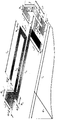
図1は、本実施形態に係る多周波アンテナの概略構成の一例であり、(a)は展開した状態を示し、(b)は立体化した状態を示す。図1(a)に示す折り曲げ線A及びBで折り曲げると、図1(b)に示す状態となる。第1の放射素子1と第2の放射素子2は、3次元で折り曲げられてアーム状に形成されている。本実施形態に係る多周波アンテナは、平板状の地板10と、給電点11と、共通給電アーム12と、第1の放射素子1と、第2の放射素子2を備える。
Embodiments of the present invention will be described with reference to the accompanying drawings. The embodiment described below is an example of the configuration of the present invention, and the present invention is not limited to the following embodiment.
FIG. 1 is an example of a schematic configuration of a multi-frequency antenna according to the present embodiment, where (a) shows a developed state and (b) shows a three-dimensional state. When bent along the folding lines A and B shown in FIG. 1A, the state shown in FIG. 1B is obtained. The
アンテナを展開した状態では、地板10、第1の放射素子1及び第2の放射素子2は同一平面上に配置されており、アンテナ全体が平面構造を有している。アンテナの構成材料は、コストが安いフレクシブルプリント基板(FPC)が好ましい。この場合、FPC上にアンテナが形成される。FPCにてアンテナを構成することで、アンテナが曲げ易く、簡単に情報端末機器に搭載することができる。なお、本実施形態に係る多周波アンテナは、FPCに限定するものではない。例えば、薄い樹脂のシート上に銅板を張った構成としてもよい。
In a state where the antenna is deployed, the
共通給電アーム12は、給電点11に一端が接続され、地板10の外縁から離れる方向に伸びる。共通給電アーム12は、高周波電力が給電点11から給電される。給電点11は、地板10の外縁に接続され、高周波電力が給電される。給電点11からの高周波電力が、共通給電アーム12を通して第1の放射素子1及び第2の放射素子2を励起する。共通給電アーム12は、第1の放射素子1及び第2の放射素子2の一端と接続され、第1の放射素子1及び第2の放射素子2に給電する。
The common
第1の放射素子1は、3次元で折り曲げられてアーム状に形成されている。また、第1の放射素子1は、共通給電アーム12の他端に接続され、共通給電アーム12からの給電をアームの一端から受ける。第2の放射素子2は、共通給電アーム12に対して第1の放射素子1が伸びる方向と対向する側に、3次元で折り曲げられてアーム状に形成されている。また、第2の放射素子2は、共通給電アーム12に一端が接続され、共通給電アーム12からの給電をアームの一端から受ける。第1の放射素子1及び第2の放射素子2が3次元に折り曲げられていることで、小型化と共に、高周波側の周波数帯との間隔を調整することができる。
The
第2の放射素子2の基本共振周波数は、第1の放射素子1の2次高調波の周波数と略同一であることが好ましい。第1の放射素子1の折り曲げ方で、第1の放射素子1の2次高調波の周波数を低周波側に移動させることができる。また、第1の放射素子1と第2の放射素子2を組み合わせることで、高周波側の周波数帯域を広げることができる。
The fundamental resonance frequency of the
共通給電アーム12に接続されている第1の放射素子1の一端から給電点11までの距離が、共通給電アーム12に接続されている第2の放射素子2の一端から給電点11までの距離と異なることが好ましい。一般的な折り曲げたアンテナの場合、放射抵抗の減衰及びアンテナのインピーダンスのリアクタンス成分の増加のため、整合をとることが困難である。そこで、放射抵抗の増加及びリアクタンス成分を調整するために、第1の放射素子1と第2の放射素子2とで段差をつける。段差をつけることで、給電点11のところに誘電の成分を与えて、誘電の成分が給電点11での容量成分を相殺する。
The distance from one end of the
また、共通給電アーム12の両端は、それぞれ、給電点11及び第1の放射素子1の一端と接続されていることが好ましい。例えば、共通給電アーム12の端部に第1の放射素子1が接続され、共通給電アーム12の給電点11から第1の放射素子1との接続点までの間に第2の放射素子2が接続される。また、共通給電アーム12に第2の放射素子2が接続され、第1の放射素子1は、第2の放射素子2に接続されていてもよい。
Moreover, it is preferable that both ends of the
第1の放射素子1は、共通給電アーム12に接続されているアームの一端から順に、折り曲げられて形成された直線状のアーム1a、アーム1b、アーム1c、アーム1d、アーム1e、アーム1fを備える。第2の放射素子2は、共通給電アーム12に接続されているアームの一端から順に、折り曲げられて形成された直線状のアーム2a、アーム2b、アーム2c、アーム2d、アーム2e、アーム2fを備える。ここで、アーム1aとアーム2aは、共通給電アーム12に対して逆方向に設けられていることが好ましい。これにより、第1の放射素子1と第2の放射素子2による相互結合を抑圧することができ、設計が容易になる。
The
共通給電アーム12、アーム1a、アーム2a、アーム2b、アーム2c及びアーム2dは、地板10の配置される平面上に配置されている。アーム1c、アーム1d、アーム1e、アーム1f、及びアーム2fは、地板10の配置される平面と平行な平面上に配置されている。アーム1bは地板10の配置される平面に対して略直角である。アーム1aとアーム1dは対向している。アーム1fの一部はアーム1dとで略平行である。共通給電アーム12とアーム1c及びアーム1cとアーム1eは対向している。このように、アーム同士が略平行に配置され、対向していることで、高周波側の帯域を低周波側に広げることができる。
The common
アーム1cの長さは、共通給電アーム12の長さよりも短いことが好ましい。共通給電アーム12とアーム1c両者は電流の流れが逆であるため、両者の長さが同じであればアンテナの利得が落ちる場合がある。そこで、両者の長さに差をもたせることで、アンテナの利得低下を防ぐことができる。
The length of the
共通給電アーム12とアーム2b、アーム2bとアーム2dは対向している。アーム2aとアーム2cは略平行である。アーム2eは地板10の配置される平面に対して略直角である。アーム1bとアーム2eは略平行である。アーム2fとアーム2dは対向している。このように、アーム同士が略平行に配置され、対向していることで、高周波側の帯域を低周波側に広げることができる。
The common
以上説明した2つの第1の放射素子1及び第2の放射素子2を利用することで、3共振を発生させることができる。第1の放射素子1を用いて、低周波側の基本モードと高次モードを制御し、第2の放射素子2を利用することで、高周波側の基本モードを調整することができる。また、第1の放射素子1と第2の放射素子2の折り曲げた部分の位置(または、相対的な長さ)で、それぞれの基本モードと高次モードの間隔を調整することができ、共振周波数の間隔を制御することが可能である。アーム状の2つの放射素子を利用することで、低周波側の高次モードと高周波側の基本モードを足すことが可能であり、高周波側の帯域を広げることができる。
By using the two
実施形態に係るアンテナの評価を行った。図2は、本実施例に係るアンテナの形状及び設計パラメータを示す鳥瞰図である。図3は、本実施例に係るアンテナの形状、設計パラメータ及びその符号である。第1の放射素子1と第2の放射素子2で形成されたアンテナエレメントのみは全体の大きさが38mm×15mm×4mmとなっている。なお、使用した地板10の大きさ(Lg×Wg)は、携帯電話の典型的な値のLg=70mm、Wg=40mmとした。符号ごとの数値を図4に示す。
The antenna according to the embodiment was evaluated. FIG. 2 is a bird's-eye view showing the shape and design parameters of the antenna according to the present embodiment. FIG. 3 shows the shape, design parameters, and symbols of the antenna according to the present embodiment. Only the antenna element formed by the
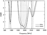
図5は、実施例に係るアンテナの電圧定在波比特性を示す。横軸は周波数(MHz)、縦軸はVSWR(Voltage Standing Wave Ratio)を示す。実線(meas)は実測値、破線(simu)はシミュレーション値である。第1の放射素子1と第2の放射素子2の共振によって、一点鎖線で表している目的としている周波数帯のGSM、DCS、PCS、UMTS、WiMAX帯に3共振が発生していることが分かる。また、VSWR<3.5を基準と仮定すると、900MHz帯(920MHz中心)と、3GのバンドのDCS、PCS、UMTS(1910MHz中心)と、WiMAX帯(2580MHz中心)の帯域幅が125.0MHz、785.0MHz、245.0MHzであった。
FIG. 5 shows the voltage standing wave ratio characteristics of the antenna according to the example. The horizontal axis represents frequency (MHz), and the vertical axis represents VSWR (Voltage Standing Wave Ratio). A solid line (meas) is an actual measurement value, and a broken line (simu) is a simulation value. It can be seen that due to the resonance of the
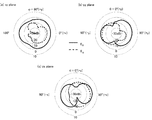
図6は、実施例に係るアンテナのGSM帯における放射指向性であり、(a)はxy平面、(b)はyz平面、(c)はzx平面を示す。xy平面での最大利得、最低利得及び平均利得は、それぞれ、中心周波数を920MHzとして、−0.2dBi、−6.6dBi、−2.1dBiであった。 6A and 6B show radiation directivities in the GSM band of the antenna according to the embodiment, where FIG. 6A shows the xy plane, FIG. 6B shows the yz plane, and FIG. 6C shows the zx plane. The maximum gain, the minimum gain, and the average gain in the xy plane were −0.2 dBi, −6.6 dBi, and −2.1 dBi, respectively, with a center frequency of 920 MHz.
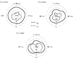
図7は、実施例に係るアンテナの2GHz帯における放射指向性であり、(a)はxy平面、(b)はyz平面、(c)はzx平面を示す。xy平面での最大利得、最低利得及び平均利得は、それぞれ、中心周波数を2020MHzとして、3.0dBi、0.0dBi、1.5dBiであった。 7A and 7B show radiation directivities in the 2 GHz band of the antenna according to the example. FIG. 7A shows the xy plane, FIG. 7B shows the yz plane, and FIG. 7C shows the zx plane. The maximum gain, the minimum gain, and the average gain in the xy plane were 3.0 dBi, 0.0 dBi, and 1.5 dBi, respectively, with a center frequency of 2020 MHz.
図8は、実施例に係るアンテナのWiMAX帯における放射指向性であり、(a)はxy平面、(b)はyz平面、(c)はzx平面を示す。xy平面での最大利得、最低利得及び平均利得は、それぞれ、中心周波数を2575MHzとして、−1.9dBi、−24.6dBi、−6.3dBiであった。 8A and 8B show radiation directivities in the WiMAX band of the antenna according to the example, where FIG. 8A shows the xy plane, FIG. 8B shows the yz plane, and FIG. 8C shows the zx plane. The maximum gain, the minimum gain, and the average gain in the xy plane were −1.9 dBi, −24.6 dBi, and −6.3 dBi with a center frequency of 2575 MHz, respectively.
そして、各周波数帯での放射指向性は、図6、図7、図8に示すように、モノポールの近い特性をもつことが分かる。 And it turns out that the radiation directivity in each frequency band has the characteristic close | similar to a monopole, as shown in FIG.6, FIG.7, FIG.8.
本発明は、ノートパソコン、PDA(携帯型情報機器)端末、携帯電話又はVICS(Vehicle Information and Communication System)などの情報端末機器に内蔵する多周波型アンテナに利用することができる。 INDUSTRIAL APPLICABILITY The present invention can be used for a multi-frequency antenna built in an information terminal device such as a notebook personal computer, a PDA (portable information device) terminal, a mobile phone, or a VICS (Vehicle Information and Communication System).
1 第1の放射素子
1a、1b、1c、1d、1e、1f アーム
2 第2の放射素子
2a、2b、2c、2d、2e、2f アーム
10 地板
11 給電点
12 共通給電アーム
DESCRIPTION OF
Claims (6)
前記地板の外縁に接続され、高周波電力が給電される給電点と、
前記給電点に一端が接続され、前記地板の前記外縁から離れる方向に伸びる共通給電アームと、
3次元で折り曲げられてアーム状に形成され、前記共通給電アームの他端に接続された第1の放射素子と、
を備えることを特徴とする多周波アンテナ。 With the main plate,
A feeding point connected to the outer edge of the ground plane and fed with high-frequency power,
One end connected to the feeding point, a common feeding arm extending in a direction away from the outer edge of the ground plane,
A first radiating element bent in three dimensions and formed into an arm shape and connected to the other end of the common feeding arm;
A multi-frequency antenna comprising:
前記第2の放射素子は、前記一端から順に、折り曲げられて形成された直線状のアーム2a、アーム2b、アーム2c、アーム2d、アーム2e、アーム2fを備え、
前記アーム1aと前記アーム2aは、前記共通給電アームに対して逆方向に設けられ、
前記共通給電アーム、前記アーム1a、前記アーム2a、前記アーム2b、前記アーム2c及び前記アーム2dは、前記地板の配置される平面上に配置され、
前記アーム1c、前記アーム1d、前記アーム1e、前記アーム1f、及び前記アーム2fは、前記地板の配置される平面と平行な平面上に配置され、
前記アーム1bは前記地板の配置される平面に対して略直角であり、
前記アーム1aと前記アーム1dは対向し、
前記アーム1fの一部は前記アーム1dとで略平行であり、
前記共通給電アームと前記アーム1c及び前記アーム1cと前記アーム1eは対向し、
前記共通給電アームと前記アーム2b及び前記アーム2bと前記アーム2dは対向し、
前記アーム2aと前記アーム2cは略平行であり、
前記アーム2eは前記地板の配置される平面に対して略直角であり、
前記アーム1bと前記アーム2eは略平行であり、
前記アーム2fと前記アーム2dは対向していることを特徴とする請求項2又は3に記載の多周波アンテナ。 The first radiating element includes a linear arm 1a, an arm 1b, an arm 1c, an arm 1d, an arm 1e, and an arm 1f formed by bending in order from the one end.
The second radiating element includes a linear arm 2a, an arm 2b, an arm 2c, an arm 2d, an arm 2e, and an arm 2f that are bent and formed in order from the one end.
The arm 1a and the arm 2a are provided in opposite directions with respect to the common power supply arm,
The common power supply arm, the arm 1a, the arm 2a, the arm 2b, the arm 2c, and the arm 2d are arranged on a plane on which the base plate is arranged,
The arm 1c, the arm 1d, the arm 1e, the arm 1f, and the arm 2f are arranged on a plane parallel to the plane on which the base plate is arranged,
The arm 1b is substantially perpendicular to the plane on which the ground plane is disposed,
The arm 1a and the arm 1d face each other,
A part of the arm 1f is substantially parallel to the arm 1d,
The common feeding arm and the arm 1c, and the arm 1c and the arm 1e face each other,
The common power supply arm and the arm 2b, and the arm 2b and the arm 2d face each other.
The arm 2a and the arm 2c are substantially parallel,
The arm 2e is substantially perpendicular to the plane on which the ground plane is disposed,
The arm 1b and the arm 2e are substantially parallel,
The multi-frequency antenna according to claim 2 or 3, wherein the arm 2f and the arm 2d are opposed to each other.
Priority Applications (1)
| Application Number | Priority Date | Filing Date | Title |
|---|---|---|---|
| JP2008201482A JP5063521B2 (en) | 2008-08-05 | 2008-08-05 | Multi-frequency antenna |
Applications Claiming Priority (1)
| Application Number | Priority Date | Filing Date | Title |
|---|---|---|---|
| JP2008201482A JP5063521B2 (en) | 2008-08-05 | 2008-08-05 | Multi-frequency antenna |
Publications (2)
| Publication Number | Publication Date |
|---|---|
| JP2010041359A true JP2010041359A (en) | 2010-02-18 |
| JP5063521B2 JP5063521B2 (en) | 2012-10-31 |
Family
ID=42013433
Family Applications (1)
| Application Number | Title | Priority Date | Filing Date |
|---|---|---|---|
| JP2008201482A Expired - Fee Related JP5063521B2 (en) | 2008-08-05 | 2008-08-05 | Multi-frequency antenna |
Country Status (1)
| Country | Link |
|---|---|
| JP (1) | JP5063521B2 (en) |
Cited By (6)
| Publication number | Priority date | Publication date | Assignee | Title |
|---|---|---|---|---|
| JP2012109875A (en) * | 2010-11-18 | 2012-06-07 | Fujitsu Ltd | Antenna device and wireless communication device |
| WO2012124247A1 (en) * | 2011-03-16 | 2012-09-20 | パナソニック株式会社 | Antenna device, and wireless communication device |
| WO2013051187A1 (en) * | 2011-10-06 | 2013-04-11 | パナソニック株式会社 | Antenna device and wireless communication device |
| WO2013051188A1 (en) * | 2011-10-06 | 2013-04-11 | パナソニック株式会社 | Antenna device and wireless communication device |
| WO2013061502A1 (en) * | 2011-10-27 | 2013-05-02 | パナソニック株式会社 | Antenna device and wireless communication device |
| JP5588519B2 (en) * | 2011-06-02 | 2014-09-10 | パナソニック株式会社 | Antenna device |
Citations (5)
| Publication number | Priority date | Publication date | Assignee | Title |
|---|---|---|---|---|
| JP2004104419A (en) * | 2002-09-09 | 2004-04-02 | Hitachi Cable Ltd | Antenna for portable radio |
| JP2005252526A (en) * | 2004-03-03 | 2005-09-15 | Tdk Corp | Antenna system, electronic equipment using the same, and radio communication card |
| WO2007046285A1 (en) * | 2005-10-17 | 2007-04-26 | Nec Corporation | Antenna unit and communication device |
| JP2007123982A (en) * | 2005-10-25 | 2007-05-17 | Sony Ericsson Mobilecommunications Japan Inc | Multiband compatible antenna system and communication terminal |
| JP2007214961A (en) * | 2006-02-10 | 2007-08-23 | Casio Hitachi Mobile Communications Co Ltd | Antenna system |
-
2008
- 2008-08-05 JP JP2008201482A patent/JP5063521B2/en not_active Expired - Fee Related
Patent Citations (5)
| Publication number | Priority date | Publication date | Assignee | Title |
|---|---|---|---|---|
| JP2004104419A (en) * | 2002-09-09 | 2004-04-02 | Hitachi Cable Ltd | Antenna for portable radio |
| JP2005252526A (en) * | 2004-03-03 | 2005-09-15 | Tdk Corp | Antenna system, electronic equipment using the same, and radio communication card |
| WO2007046285A1 (en) * | 2005-10-17 | 2007-04-26 | Nec Corporation | Antenna unit and communication device |
| JP2007123982A (en) * | 2005-10-25 | 2007-05-17 | Sony Ericsson Mobilecommunications Japan Inc | Multiband compatible antenna system and communication terminal |
| JP2007214961A (en) * | 2006-02-10 | 2007-08-23 | Casio Hitachi Mobile Communications Co Ltd | Antenna system |
Cited By (9)
| Publication number | Priority date | Publication date | Assignee | Title |
|---|---|---|---|---|
| JP2012109875A (en) * | 2010-11-18 | 2012-06-07 | Fujitsu Ltd | Antenna device and wireless communication device |
| WO2012124247A1 (en) * | 2011-03-16 | 2012-09-20 | パナソニック株式会社 | Antenna device, and wireless communication device |
| JP5588519B2 (en) * | 2011-06-02 | 2014-09-10 | パナソニック株式会社 | Antenna device |
| WO2013051187A1 (en) * | 2011-10-06 | 2013-04-11 | パナソニック株式会社 | Antenna device and wireless communication device |
| WO2013051188A1 (en) * | 2011-10-06 | 2013-04-11 | パナソニック株式会社 | Antenna device and wireless communication device |
| JPWO2013051188A1 (en) * | 2011-10-06 | 2015-03-30 | パナソニック インテレクチュアル プロパティ コーポレーション オブアメリカPanasonic Intellectual Property Corporation of America | ANTENNA DEVICE AND WIRELESS COMMUNICATION DEVICE |
| US9070980B2 (en) | 2011-10-06 | 2015-06-30 | Panasonic Intellectual Property Corporation Of America | Small antenna apparatus operable in multiple bands including low-band frequency and high-band frequency and increasing bandwidth including high-band frequency |
| WO2013061502A1 (en) * | 2011-10-27 | 2013-05-02 | パナソニック株式会社 | Antenna device and wireless communication device |
| US9019163B2 (en) | 2011-10-27 | 2015-04-28 | Panasonic Intellectual Property Corporation Of America | Small antenna apparatus operable in multiple bands including low-band frequency and high-band frequency with ultra wide bandwidth |
Also Published As
| Publication number | Publication date |
|---|---|
| JP5063521B2 (en) | 2012-10-31 |
Similar Documents
| Publication | Publication Date | Title |
|---|---|---|
| US8248312B2 (en) | Antenna and wireless communication apparatus | |
| US6917339B2 (en) | Multi-band broadband planar antennas | |
| EP1788663B1 (en) | Folded dipole antenna device and mobile radio terminal | |
| US7319432B2 (en) | Multiband planar built-in radio antenna with inverted-L main and parasitic radiators | |
| US8259014B2 (en) | Multi-loop antenna structure and hand-held electronic device using the same | |
| US7268730B2 (en) | Small broadband monopole antenna having perpendicular ground plane with electromagnetically coupled feed | |
| EP1750323A1 (en) | Multi-band antenna device for radio communication terminal and radio communication terminal comprising the multi-band antenna device | |
| US20090051614A1 (en) | Folded dipole antenna | |
| JP2007123982A (en) | Multiband compatible antenna system and communication terminal | |
| JP2005538623A (en) | Combined multiband antenna | |
| JP4649486B2 (en) | Mobile terminal antenna | |
| JP5063521B2 (en) | Multi-frequency antenna | |
| JP4446203B2 (en) | Antenna element and broadband antenna device | |
| Jing et al. | Compact planar monopole antenna for multi-band mobile phones | |
| CN102055061B (en) | Multi-frequency mobile communication device and its antenna | |
| JP2008113462A (en) | Coupled multiband antenna | |
| Kwak et al. | A folded planar inverted-F antenna for GSM/DCS/Bluetooth triple-band application | |
| JP4171008B2 (en) | Antenna device and portable radio | |
| Liao et al. | Miniaturized PIFA antenna for 2.4 GHz ISM band applications | |
| WO2004025781A1 (en) | Loop antenna | |
| JP5008602B2 (en) | antenna | |
| Rhyu et al. | Multi-band hybrid antenna for ultra-thin mobile phone applications | |
| KR20080095597A (en) | Broadband internal antenna | |
| CN100468861C (en) | Multiband Radio Antenna | |
| JP5005466B2 (en) | Multi-frequency antenna |
Legal Events
| Date | Code | Title | Description |
|---|---|---|---|
| A621 | Written request for application examination |
Free format text: JAPANESE INTERMEDIATE CODE: A621 Effective date: 20110610 |
|
| A977 | Report on retrieval |
Free format text: JAPANESE INTERMEDIATE CODE: A971007 Effective date: 20120330 |
|
| A131 | Notification of reasons for refusal |
Free format text: JAPANESE INTERMEDIATE CODE: A131 Effective date: 20120501 |
|
| A521 | Written amendment |
Free format text: JAPANESE INTERMEDIATE CODE: A523 Effective date: 20120629 |
|
| TRDD | Decision of grant or rejection written | ||
| A01 | Written decision to grant a patent or to grant a registration (utility model) |
Free format text: JAPANESE INTERMEDIATE CODE: A01 Effective date: 20120731 |
|
| A01 | Written decision to grant a patent or to grant a registration (utility model) |
Free format text: JAPANESE INTERMEDIATE CODE: A01 |
|
| A61 | First payment of annual fees (during grant procedure) |
Free format text: JAPANESE INTERMEDIATE CODE: A61 Effective date: 20120807 |
|
| R150 | Certificate of patent (=grant) or registration of utility model |
Free format text: JAPANESE INTERMEDIATE CODE: R150 |
|
| FPAY | Renewal fee payment (prs date is renewal date of database) |
Free format text: PAYMENT UNTIL: 20150817 Year of fee payment: 3 |
|
| LAPS | Cancellation because of no payment of annual fees |