JP2010039820A - Control data generation device - Google Patents
Control data generation device Download PDFInfo
- Publication number
- JP2010039820A JP2010039820A JP2008202922A JP2008202922A JP2010039820A JP 2010039820 A JP2010039820 A JP 2010039820A JP 2008202922 A JP2008202922 A JP 2008202922A JP 2008202922 A JP2008202922 A JP 2008202922A JP 2010039820 A JP2010039820 A JP 2010039820A
- Authority
- JP
- Japan
- Prior art keywords
- change
- control data
- scale
- scale characteristic
- predetermined
- Prior art date
- Legal status (The legal status is an assumption and is not a legal conclusion. Google has not performed a legal analysis and makes no representation as to the accuracy of the status listed.)
- Granted
Links
- 230000008859 change Effects 0.000 claims abstract description 194
- 238000001514 detection method Methods 0.000 claims description 83
- 238000006243 chemical reaction Methods 0.000 claims description 40
- 238000000034 method Methods 0.000 claims description 23
- 230000004044 response Effects 0.000 abstract description 3
- 230000006870 function Effects 0.000 description 26
- 230000007246 mechanism Effects 0.000 description 18
- 230000008569 process Effects 0.000 description 17
- 230000007704 transition Effects 0.000 description 6
- 238000010586 diagram Methods 0.000 description 5
- 238000012886 linear function Methods 0.000 description 4
- 230000005236 sound signal Effects 0.000 description 4
- 238000004590 computer program Methods 0.000 description 2
- 230000007423 decrease Effects 0.000 description 2
- 230000003247 decreasing effect Effects 0.000 description 1
- 230000000694 effects Effects 0.000 description 1
- 230000003287 optical effect Effects 0.000 description 1
- 230000009467 reduction Effects 0.000 description 1
- 238000013341 scale-up Methods 0.000 description 1
Images


Classifications
-
- G—PHYSICS
- G11—INFORMATION STORAGE
- G11B—INFORMATION STORAGE BASED ON RELATIVE MOVEMENT BETWEEN RECORD CARRIER AND TRANSDUCER
- G11B27/00—Editing; Indexing; Addressing; Timing or synchronising; Monitoring; Measuring tape travel
- G11B27/02—Editing, e.g. varying the order of information signals recorded on, or reproduced from, record carriers
- G11B27/031—Electronic editing of digitised analogue information signals, e.g. audio or video signals
-
- G—PHYSICS
- G06—COMPUTING; CALCULATING OR COUNTING
- G06F—ELECTRIC DIGITAL DATA PROCESSING
- G06F3/00—Input arrangements for transferring data to be processed into a form capable of being handled by the computer; Output arrangements for transferring data from processing unit to output unit, e.g. interface arrangements
- G06F3/01—Input arrangements or combined input and output arrangements for interaction between user and computer
- G06F3/03—Arrangements for converting the position or the displacement of a member into a coded form
- G06F3/033—Pointing devices displaced or positioned by the user, e.g. mice, trackballs, pens or joysticks; Accessories therefor
- G06F3/0362—Pointing devices displaced or positioned by the user, e.g. mice, trackballs, pens or joysticks; Accessories therefor with detection of 1D translations or rotations of an operating part of the device, e.g. scroll wheels, sliders, knobs, rollers or belts
-
- G—PHYSICS
- G11—INFORMATION STORAGE
- G11B—INFORMATION STORAGE BASED ON RELATIVE MOVEMENT BETWEEN RECORD CARRIER AND TRANSDUCER
- G11B27/00—Editing; Indexing; Addressing; Timing or synchronising; Monitoring; Measuring tape travel
- G11B27/02—Editing, e.g. varying the order of information signals recorded on, or reproduced from, record carriers
- G11B27/031—Electronic editing of digitised analogue information signals, e.g. audio or video signals
- G11B27/038—Cross-faders therefor
-
- G—PHYSICS
- G11—INFORMATION STORAGE
- G11B—INFORMATION STORAGE BASED ON RELATIVE MOVEMENT BETWEEN RECORD CARRIER AND TRANSDUCER
- G11B27/00—Editing; Indexing; Addressing; Timing or synchronising; Monitoring; Measuring tape travel
- G11B27/10—Indexing; Addressing; Timing or synchronising; Measuring tape travel
- G11B27/34—Indicating arrangements
-
- H—ELECTRICITY
- H04—ELECTRIC COMMUNICATION TECHNIQUE
- H04H—BROADCAST COMMUNICATION
- H04H60/00—Arrangements for broadcast applications with a direct linking to broadcast information or broadcast space-time; Broadcast-related systems
- H04H60/02—Arrangements for generating broadcast information; Arrangements for generating broadcast-related information with a direct linking to broadcast information or to broadcast space-time; Arrangements for simultaneous generation of broadcast information and broadcast-related information
- H04H60/04—Studio equipment; Interconnection of studios
Abstract
Description
この発明は、オーディオミキサ装置あるいはその他の制御機器において用いられる手動及び自動操作の双方が可能な操作子の操作位置を検出して該操作位置に対応した制御データを発生する制御データ発生装置に関し、特に、自動操作がなされた際に生じた位置決め誤差を、その直後になされる手動操作に際して、実効的に解消することで、違和感のない制御データ発生を行うことができるようにした制御データ発生装置に関する。 The present invention relates to a control data generation device that detects an operation position of an operator capable of both manual and automatic operation used in an audio mixer device or other control equipment and generates control data corresponding to the operation position. In particular, a control data generation device that can generate control data without a sense of incongruity by effectively eliminating positioning errors caused when automatic operation is performed immediately after manual operation. About.
オーディオミキサ装置においては、ミキシングしようとするオーディオ信号あるいは出力しようとするオーディオ信号のレベルや周波数特性などを調整・設定するために、操作者によって手動操作されるフェーダ(スライド型操作子)が設けられている。このフェーダには、電動フェーダとして構成され、手動及び自動操作の双方が可能なタイプのものがある(例えば特許文献1及び2)。
上記特許文献2においては、各フェーダに取り付けた位置センサの位置対出力特性に各センサ間でバラツキがあること(センサ個体誤差)、及びフェーダ構造体に対する位置センサの取り付け誤差(各フェーダ間でのバラツキ)があること等に鑑み、これらの誤差又はバラツキを解消・吸収すべく、フェーダの指標位置(操作位置)と該フェーダに取り付けた位置センサの位置検出データとの対応付けを標準化するために、各フェーダ毎に前記位置検出データのキャリブレーションを行うようにしたことが示されている。これによって、どのフェーダでも、同じ指標位置に対する位置検出データとして、同じ値の位置検出データが発生されるように標準化することができる。
In
また、上記特許文献2においては、フェーダを所望の目標位置に自動的に位置決めする場合、該目標位置に対応する指標位置に対応して位置センサから得られる実際の位置検出データと目標位置として与えられるデータとの間には、上記センサ個体誤差あるいは取り付け誤差(バラツキ)等に起因する誤差が生じることに鑑み、これを解消するために、目標位置データがそれに対応する指標位置に対応する実際の位置検出データの値を指示するように、目標位置データの変換を行うようにしたことが示されている。このように変換された目標位置データにフェーダを位置決めすることで、上記センサ個体誤差あるいは取り付け誤差を補償したフェーダ自動位置決めが行える。
In
ところで、一般に、モータ駆動に応じてフェーダを自動的に位置決めするための自動位置決め機構が持つ固有の位置決め精度と、位置センサが持つ固有の位置検出精度には違いがあり、特に最近では、位置センサとしてエンコーダを用いることにより位置検出精度が精密になってきているので、自動位置決め機構が持つ位置決め精度はそれよりも粗いものとなっている。このように、自動位置決め機構が持つ位置決め精度よりも位置センサの位置検出精度が精密である場合は、次のような問題が生じる。すなわち、自動位置決め機構がその位置決め精度の範囲内で目標位置にフェーダを正確に位置決めしたとしても、位置センサの持つ位置検出精度のレベルでは目標位置から幾分ずれた位置に位置決めされているものとして位置検出されることが起こる。そのような場合、自動位置決めされた直後のフェーダを手動で操作した際に、その手動操作に応じて位置センサから出力されるフェーダ操作位置検出データの初期値として、本来の初期値であるはずの目標位置から幾分ずれた値が出力されてしまうことになり、好ましくない。例えば、−10dBの目標位置に対して自動位置決め機構が0.02dBの誤差で−9.98dBの位置に位置決めしたとすると、位置センサはそのような誤差を含む位置を正確に検出し、−9.98dBの位置検出データを出力する、という場合がある。このような場合、操作者がフェーダを自動位置決めされた目標位置の−10dBから−11dBの方に動かそうとすると、実際のフェーダ出力値は、−9.98dBから始まって−10dBを通り、−11dBの方に変化することになる。すなわち、手動操作の初期値は目標位置である−10dBであるはずなのに、実際のフェーダ出力値はそれとは異なる−9.98dBから始まってしまうことになり、そのような位置検出データに基づいてオーディオ信号のレベル調整等の所定の制御を行った場合、幾分誤った制御がなされてしまうことになり、好ましくない。例えば、操作者に対して違和感を与えることになる。 By the way, in general, there is a difference between the inherent positioning accuracy of the automatic positioning mechanism for automatically positioning the fader according to the motor drive and the inherent position detection accuracy of the position sensor. As the position detection accuracy has become more precise by using an encoder, the positioning accuracy of the automatic positioning mechanism is coarser than that. Thus, when the position detection accuracy of the position sensor is more precise than the positioning accuracy of the automatic positioning mechanism, the following problem occurs. In other words, even if the automatic positioning mechanism accurately positions the fader at the target position within the range of the positioning accuracy, it is assumed that the position sensor is positioned at a position slightly deviated from the target position at the position detection accuracy level It happens that the position is detected. In such a case, when the fader immediately after the automatic positioning is manually operated, the initial value of the fader operation position detection data output from the position sensor according to the manual operation should be the original initial value. A value slightly deviated from the target position is output, which is not preferable. For example, if the automatic positioning mechanism is positioned at a position of −9.98 dB with an error of 0.02 dB with respect to a target position of −10 dB, the position sensor accurately detects a position including such an error, and −9 In some cases, position detection data of .98 dB is output. In such a case, when the operator tries to move the fader from −10 dB to −11 dB of the automatically positioned target position, the actual fader output value starts from −9.98 dB, passes through −10 dB, − It will change to 11 dB. That is, although the initial value of manual operation should be -10 dB which is the target position, the actual fader output value will start from -9.98 dB which is different from the target position. Audio based on such position detection data When predetermined control such as signal level adjustment is performed, a somewhat incorrect control is performed, which is not preferable. For example, the operator feels uncomfortable.
上述の従来技術においては、このような自動位置決め機構の持つ固有の位置決め精度に起因する誤差の問題を根本的には解決することができない。そのため、そのような不都合が生じないようにするには、自動位置決め機構が持つ位置決め精度よりも位置センサの位置検出精度が粗くなるように設定するしかなかった。しかし、そうすると、せっかく高分解能の位置センサを備えたにもかかわらず、操作子の操作位置検出を粗い分解能でしか行うことができないことになり、資源の有効活用ができないという問題が生じる。 In the above-described conventional technology, the problem of errors due to the inherent positioning accuracy of such an automatic positioning mechanism cannot be fundamentally solved. Therefore, in order to prevent such inconvenience, the position detection accuracy of the position sensor has to be set to be coarser than the positioning accuracy of the automatic positioning mechanism. However, in this case, although the high-resolution position sensor is provided, the operation position of the operation element can be detected only with a coarse resolution, and there is a problem that the resources cannot be effectively used.
本発明は上述の点に鑑みてなされたもので、自動操作がなされた際に生じた位置決め誤差を、その直後になされる手動操作に際して、実効的に解消することで、違和感のない制御データ発生を行うことができるようにし、もって高分解能の位置センサを有効に活用しうるようにした制御データ発生装置を提供しようとするものである。 The present invention has been made in view of the above-mentioned points. Control data generation without a sense of incongruity can be achieved by effectively eliminating positioning errors caused when automatic operation is performed immediately after manual operation. Therefore, an object of the present invention is to provide a control data generating apparatus that can effectively use a high-resolution position sensor.
本発明に係る制御データ発生装置は、所定移動範囲にわたって操作可能な操作子と、前記所定移動範囲における前記操作子の現操作位置に応じた位置データを出力する位置検出手段と、前記位置検出手段で検出した位置データを所定のスケール特性で制御データに変換する変換手段と、指令された目標位置に前記操作子を位置決めする自動位置決め手段であって、この自動位置決め手段による位置決め精度は前記位置検出手段による位置検出精度よりも粗く、そのため、前記位置検出手段による位置検出精度に対して所定の誤差範囲内で前記目標位置への位置決めが行われる前記自動位置決め手段と、前記自動位置決め手段による位置決め完了時において変更スケール特性を適用するスケール変更制御手段であって、該変更スケール特性においては、前記位置決め完了時において前記位置検出手段から出力される位置データに対応して前記所定のスケール特性上の前記目標位置に対応する制御データが出力されるように起点を設定すると共に、前記起点の位置から少なくとも前記目標位置に達するまでの区間を含む第1の変更区間を設定し、前記位置検出手段から出力される位置データに対応する前記制御データが、前記起点に対応する制御データから該第1の変更区間の終点の位置に対応する前記所定のスケール特性上の制御データまで第1の変更スケールに従って漸次変化するように変更し、前記操作子の位置が前記第1の変更区間の終点に達したならば前記変更スケール特性の適用を解除する前記スケール変更制御手段とを備える。
The control data generating apparatus according to the present invention includes an operation element operable over a predetermined movement range, a position detection unit that outputs position data corresponding to a current operation position of the operation element in the predetermined movement range, and the position detection unit Conversion means for converting the position data detected in
本発明においては、前記自動位置決め手段による位置決め完了時において変更スケール特性を適用するスケール変更制御手段が設けられており、このスケール変更手段において適用される変更スケール特性は、上記のような特性からなっている。従って、自動位置決め手段による位置決め結果が位置検出手段の位置検出精度からみると誤差を含んでいたとしても、スケール変更手段によって適用される変更スケール特性により、前記位置決め完了時において前記位置検出手段から出力される位置データに対応して前記所定のスケール特性上の前記目標位置に対応する制御データが出力されるように起点が設定されるので、位置決め完了時において位置検出手段から出力される位置データに対応する制御データが所定のスケール特性上の目標位置に対応する制御データになるように変更されることになり、見掛け上誤差が無いように処理される。従って、自動位置決めの後に、前記操作子の手動操作が行われたとき、その手動操作に応じて位置検出手段から出力される位置データに対応する制御データの初期値は、本来の初期値である目標位置に対応する値に必ず合致されることとなり、違和感を起こさせない、不都合のない制御データの発生を行うことができる。更に、前記変更スケール特性においては、前記起点の位置から少なくとも前記目標位置に達するまでの区間を含む第1の変更区間が設定され、前記位置検出手段から出力される位置データに対応する前記制御データが、前記起点に対応する制御データから該第1の変更区間の終点の位置に対応する前記所定のスケール特性上の制御データまで第1の変更スケールに従って漸次変化するように変更するようにしているので、第1の変更区間の終点が目標位置若しくは目標位置を越えた位置に設定されることとなり、目標位置からずれた位置に停止していた操作子が目標位置の方に動かされるとき、起点で目標位置に対応する値を持つ制御データの値が一時的にでも逆行する(例えば値が増加するように操作したつもりが一時的に減少するように変化する)ことがなく、違和感のない制御データの生成を行うことができる。また、変更スケール特性から所定のスケール特性への滑らかな移行が実現される。また、自動位置決め手段による位置決め精度が位置検出手段による位置検出精度よりも粗かったとしても、問題のない制御データ生成を行うことができるので、高分解能の位置検出手段を有効活用できるようになる。 In the present invention, scale change control means for applying the changed scale characteristic when the positioning by the automatic positioning means is completed is provided, and the changed scale characteristic applied in the scale changing means includes the characteristics as described above. ing. Therefore, even if the positioning result by the automatic positioning means includes an error when viewed from the position detection accuracy of the position detecting means, the output from the position detecting means at the time of completion of the positioning is performed due to the changed scale characteristic applied by the scale changing means. Since the starting point is set so that the control data corresponding to the target position on the predetermined scale characteristic is output corresponding to the position data to be output, the position data output from the position detection means when the positioning is completed The corresponding control data is changed to become control data corresponding to a target position on a predetermined scale characteristic, and processing is performed so that there is no apparent error. Therefore, when the operator is manually operated after the automatic positioning, the initial value of the control data corresponding to the position data output from the position detection means according to the manual operation is the original initial value. Since the value corresponding to the target position is always matched, it is possible to generate control data without causing any sense of incongruity. Further, in the change scale characteristic, a first change section including a section from the starting position to at least the target position is set, and the control data corresponding to the position data output from the position detecting means Is changed so as to gradually change from the control data corresponding to the starting point to the control data on the predetermined scale characteristic corresponding to the position of the end point of the first change section according to the first change scale. Therefore, the end point of the first change section is set to the target position or a position beyond the target position, and when the operating element stopped at the position shifted from the target position is moved toward the target position, the starting point The value of the control data having a value corresponding to the target position will go backward even temporarily (for example, the intention to operate to increase the value will temporarily decrease) Reduction to) that no, it is possible to generate the free control data incongruity. In addition, a smooth transition from the changed scale characteristic to the predetermined scale characteristic is realized. Further, even if the positioning accuracy by the automatic positioning means is coarser than the position detection precision by the position detecting means, it is possible to generate control data without any problem, so that the high-resolution position detecting means can be effectively utilized. .
一実施例によると、前記スケール変更制御手段は、更に、前記起点の位置から前記第1の変更区間とは反対側に第2の変更区間を設定し、前記位置検出手段から出力される位置データに対応する前記制御データが、前記起点に対応する制御データから該第2の変更区間の終点の位置に対応する前記所定のスケール特性上の制御データまで第2の変更スケールに従って漸次変化するように変更し、前記操作子の位置が前記第2の変更区間の終点に達したならば前記変更スケール特性の適用を解除するものである。これにより、自動位置決めの後に、目標位置からずれた位置に停止していた操作子が目標位置とは逆の方に動かされるときも、変更スケール特性から所定のスケール特性への滑らかな移行が実現される。なお、この場合は、操作子が目標位置とは逆の方に動かされるため、起点で目標位置に対応する値を持つ制御データの値が逆行することがないので、該第2の変更区間を設定しなかったとしても逆行の問題は生じない。しかし、変更スケール特性から所定のスケール特性への滑らかな移行を実現するためには、第2の変更区間を実質的に設定することは有効である。 According to one embodiment, the scale change control means further sets a second change section on the opposite side of the first change section from the position of the starting point, and position data output from the position detection means. So that the control data corresponding to the point changes gradually from the control data corresponding to the starting point to the control data on the predetermined scale characteristic corresponding to the position of the end point of the second change section according to the second change scale. When the position of the operation element reaches the end point of the second change section, the application of the change scale characteristic is canceled. As a result, a smooth transition from the changed scale characteristic to the specified scale characteristic is realized even when the control element that has stopped at a position deviated from the target position after automatic positioning is moved in the direction opposite to the target position. Is done. In this case, since the operation element is moved in the direction opposite to the target position, the value of the control data having a value corresponding to the target position at the starting point does not go backward. Even if it is not set, the problem of retrograde does not occur. However, in order to realize a smooth transition from the changed scale characteristic to the predetermined scale characteristic, it is effective to substantially set the second changed section.
以下、添付図面を参照して本発明の一実施例を詳細に説明する。
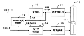
図1は、本発明に係る制御データ発生装置の一実施例である電動フェーダ10のブロック構成を示す。電動フェーダ10は、所定の直線的移動範囲にわたって操作可能なスライド式つまみ(すなわち操作子)11を有しており、該つまみ11は手動操作及び自動操作のいずれも可能な構成である。位置検出器(位置検出手段)12は、該所定の直線的移動範囲におけるつまみ(操作子)11の現操作位置を検出し、検出した現操作位置に応じた位置データをデジタル値で出力する。位置検出器12としては、公知のどのようなタイプの位置検出器を使用してもよい。例えば、可変抵抗器とアナログ/デジタル変換器の組み合わせからなるもの、磁気式リニアエンコーダ、光学式リニアエンコーダ、リニアレゾルバ、などを適宜用いてよい。駆動機構13は、つまみ11を自動的に動かすための電動モータと、該モータの駆動力をつまみ11に直線運動として伝達する機構とを含んでいる。なお、モータは回転モータ又はリニアモータのどちらでもよい。モータ制御部14は、指令された目標位置につまみ11を自動的に動かす(位置決めする)ために、駆動機構13のモータを制御するものであり、通常知られているように、位置検出器12の出力する位置データをフィードバック情報として入力し、つまみ11を目標位置に位置決めするようにフィードバック制御(若しくはサーボ制御)する。駆動機構13とモータ制御部14とで、目標位置につまみ(操作子)11を位置決めする自動位置決め手段を構成している。
Hereinafter, an embodiment of the present invention will be described in detail with reference to the accompanying drawings.
FIG. 1 shows a block configuration of an
本実施例における仕様にあっては、駆動機構13による位置決め精度は位置検出器12の位置検出精度よりも粗く、そのため、位置検出器12による位置検出精度に対して所定の誤差範囲内で目標位置への位置決めが行われる。例えば、位置検出器12による位置検出精度(検出分解能)が0.1mmであるのに対して、駆動機構13による位置決め精度は±0.5mmである。その場合、位置検出器12による位置検出精度に対する目標位置への位置決め精度の誤差範囲は、±5ポイントである(1ポイントは、位置検出器12の位置検出の最小単位を示す)。
In the specification of the present embodiment, the positioning accuracy by the
変換部(変換手段)15は、位置検出器12で検出した位置データを所定のスケール特性で制御データに変換する。この所定のスケール特性とは、本発明に係る制御データ発生装置(電動フェーダ10)の用途に応じた任意のスケール特性であってよい。例えば、検出した位置データをリニア特性で変換することで、つまみ11の操作位置に対してリニアな特性の制御データを発生するようにしてもよい。あるいは、検出した位置データを対数特性で変換することで、つまみ11の操作位置に対して対数特性の制御データ(デシベルデータ)を発生するようにしてもよい。
The converter (converter) 15 converts the position data detected by the
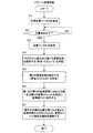
スケール変更制御部(スケール変更制御手段)16は、駆動機構13によるつまみ11の自動位置決め完了時において駆動機構13から「位置決め完了」信号が与えられると所定の変更スケール特性を適用し、変換部15から発生する制御データの値を該変更スケール特性に従って変更するよう制御する。スケール変更制御部16によって実現する変更スケール特性の基本コンセプトについて、図2に示す実例と、図3に示すフロー図に基づき、説明する。図3は、スケール変更制御部16が実行する制御の基本概念を示すフロー図であり、スケール変更制御部16の機能はこのようなコンピュータプログラムによって実現することができるし、これと同等の機能を実現するように設計された専用の制御回路によっても実現できる。
The scale change control unit (scale change control means) 16 applies a predetermined change scale characteristic when a “positioning complete” signal is given from the
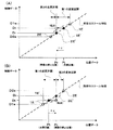
図2は、変換部15における所定のスケール特性の一例を示すと共に、変更スケール特性の一例を示すもので、位置検出器12の出力する位置データを横軸にとり、この位置データに対応して変換部15から発生される制御データをたて軸にとっている。最も単純な例として、変換部15における所定のスケール特性は、破線で示すようなリニア特性である例を示している。図において、Ptは目標位置データに対応する位置であり、Prはこの目標位置に対応してつまみ11が実際に位置決めされた位置(停止位置)を示し、PtとPrとの間に−ε又は+εの誤差がある例を示している。なお、図2(A)が−εの誤差がある例、図2(B)が+εの誤差がある例である。変更スケール特性は、起点の両側に設定された第1の変更区間と第2の変更区間とを含み、起点では、前記所定のスケール特性上の目標位置Ptに対応する制御データDtを位置データPrに対応して出力するように設定される。なお、目標位置Ptを含む区間を「第1の変更区間」と言い、その反対側の区間を「第2の変更区間」と言う。
FIG. 2 shows an example of the predetermined scale characteristic in the
図3に示すスケール変更制御は、電動フェーダ10が目標位置に自動的に位置決めされるモードとなったときスタートする。目標位置データPtを取得し(ステップS1)、目標位置への位置決めが完了したかどうかをチェックし(ステップS2)、完了したならば、位置決め完了時において位置検出器12から出力される位置データPrを取得する(ステップS3)。
The scale change control shown in FIG. 3 starts when the
ステップS4では、取得したPtとPrから起点及び第1の変更区間を設定する。起点は、位置決め完了時において位置検出器12から出力される位置データPrの位置であり、換言すれば、位置決め完了後に最初につまみ11が動かされたときの動き始めの位置である。上述のように、起点として、この位置データPrに対応して変換部15から前記所定のスケール特性上の目標位置Ptに対応する制御データDtが出力されるように設定する。これにより、実際の位置Prが目標位置Ptから多少ずれていても、目標位置Ptに対応する制御データを、つまみ11の動き初めのデータとして、発生させることができる。
In step S4, a starting point and a first change section are set from the acquired Pt and Pr. The starting point is the position of the position data Pr output from the
第1の変更区間は、前記起点の位置(Pr)から少なくとも前記目標位置(Pt)に達するまでの区間を含むように設定する。図2(A)の例では、起点から見て、目標位置Ptよりも遠い位置に第1の変更区間の終点1Eが設定されている。例えば、起点から終点1Eまでの距離は、駆動機構13における最大位置決め誤差(例えば前述の位置決め精度±0.5mm)に相当する値に固定的に定めてもよい。あるいは、目標位置に対する位置決め制御の都度、PtとPrを知得できるので、その都度、PrとPtの関係を考慮して可変的に起点から終点1Eまでの距離を設定するようにすることも可能である。
The first change interval is set so as to include an interval from the starting position (Pr) to at least the target position (Pt). In the example of FIG. 2A, the
この第1の変更区間においては、位置検出器12から出力される位置データに対応して変換部15から出力される制御データが、前記起点に対応する制御データ(Dt)から該第1の変更区間の終点1Eの位置に対応する前記所定のスケール特性上の制御データ(D1e)まで漸次変化するように、第1の変更スケールが決定(算出)され、該第1の変更スケールに従って変換を行うよう変換部15に対して指示する(ステップS6)。例えば、図2(A)において、起点から第1の変更区間の終点1Eまで延びた一点鎖線が第1の変更スケールの特性を示している。勿論、第1の変更スケールの特性は図示のような直線状の特性に限らず、滑らかな変化を実現するものであれば、どのような特性であってもよい。このように、第1の変更スケールを設定することで、第1の変更区間の終点1Eが目標位置Ptを越えた位置に設定されることとなり、目標位置からずれた位置Prに停止していたつまみ11が目標位置Ptの方に動かされるとき、起点で目標位置に対応する値Dtを持つ制御データの値が一時的にでも逆行する(例えば値が増加するように操作したつもりが一時的に減少するように変化する)ことがなく、違和感のない制御データの生成を行うことができる。また、変更スケール特性から所定のスケール特性への滑らかな移行が実現される。
In the first change section, the control data output from the
なお、起点で目標位置に対応する値Dtを持つ制御データの値が一時的にでも逆行しないようにするという目的は、第1の変更区間の終点を図2(A)の1E’のように、目標位置Ptの位置に設定することでも達成できる。ただし、この場合は、第1の変更スケールの特性は、実線で示すように、目標位置に対応する値Dtを維持するフラットなものとなる。 Note that the purpose of preventing the value of the control data having the value Dt corresponding to the target position at the starting point from going backwards even temporarily is to set the end point of the first change section as 1E ′ in FIG. This can also be achieved by setting the target position Pt. However, in this case, the characteristic of the first change scale is flat to maintain the value Dt corresponding to the target position, as shown by the solid line.
ステップS5では、上記のように設定された起点と前記第1の変更区間(目標位置Ptを含む区間)とに基づき、起点を挟んで該第1の変更区間とは反対側に第2の変更区間を設定する。起点の位置(Pr)から見て目標位置(Pt)が存在する側とは反対側の適宜の位置を第2の変更区間の位置を終点2Eとして設定し、起点から終点2Eまでが第2の変更区間となる。なお、つまみ11が起点から第2の変更区間の方に動かされるときは、起点で目標位置に対応する値を持つ制御データの値が逆行する(例えば値が減少するように操作したつもりが一時的に増加するように変化する)ことが起こらないので、該第2の変更区間の終点の位置は適宜に定めてもさしつかえない。例えば、起点と同じ位置2E’を終点として設定することも可能である。そのように第2の変更区間の終点を設定した場合は、実質的に第2の変更区間が存在しないことと等価である。すなわち、その場合は、つまみ11を起点から第2の変更区間の方に動かしたとき、すぐに、所定のスケール特性に切り替わることとなる。しかし、変更スケール特性から所定のスケール特性へと滑らかに制御データの特性を変化させるということを考慮すると、第2の変更区間の長さは、第1の変更区間と同様にある程度の長さがあるのがよい。例えば、第2の変更区間においても、起点から終点2Eまでの距離を、駆動機構13における最大位置決め誤差(例えば前述の位置決め精度±0.5mm)に相当する値に固定的に定めてもよい。
In step S5, based on the starting point set as described above and the first change section (the section including the target position Pt), the second change is made on the opposite side of the first change section with the start point in between. Set the interval. An appropriate position on the side opposite to the side where the target position (Pt) is present when viewed from the start position (Pr) is set as the
この第2の変更区間においても、位置検出器12から出力される位置データに対応して変換部15から出力される制御データが、前記起点に対応する制御データ(Dt)から該第2の変更区間の終点2Eの位置に対応する前記所定のスケール特性上の制御データ(D2e)まで漸次変化するように、第2の変更スケールが決定(算出)され、該第2の変更スケールに従って変換を行うよう変換部15に対して指示する(ステップS6)。例えば、図2(A)において、起点から第2の変更区間の終点2Eまで延びた一点鎖線が第2の変更スケールの特性を示している。勿論、第2の変更スケールの特性は図示のような直線状の特性に限らず、滑らかな変化を実現するものであれば、どのような特性であってもよい。このように、第2の変更スケールを設定することで、変更スケール特性から所定のスケール特性への滑らかな移行が実現される。なお、第2の変更区間の終点を図2(A)の2E’のように、起点と同じ位置に設定した場合は、第2の変更スケールの特性は、実線で示すように垂直になり、前述のように実質的に存在しないのと等価となる。
Also in the second change section, the control data output from the
なお、図2(B)に示すように目標位置Ptに対して位置決めされた実際の位置Prが+εの誤差を持つ場合も、図2(A)に関連して述べた上記説明をそのまま適用することができる。 Note that, as shown in FIG. 2B, even when the actual position Pr positioned with respect to the target position Pt has an error of + ε, the above description related to FIG. be able to.
図3において、ステップS7では、位置検出器12から与えられる位置データを監視しており、つまみ(操作子)11の現在位置が第1又は第2の変更区間から外れたならば、変更スケール特性の適用を解除するよう、変換部15に対して指示する。これ以後は、変更スケール制御部16による変更スケール制御を終了し、変換部15では所定のスケール特性に従う制御データの生成を行う。
In FIG. 3, in step S7, the position data given from the
このようにして、電動フェーダ10の自動操作及び手動操作に応じて、所定のスケール特性及び変更スケール特性に従って生成された制御データは、この電動フェーダ10の使用目的に応じて、適宜に利用される。
In this way, the control data generated according to the predetermined scale characteristic and the changed scale characteristic according to the automatic operation and manual operation of the
次に、図4以降の図を参照して、上記電動フェーダ10をオーディオ信号用あるいはビデオ信号用のデジタルミキサ装置において装備した実施例について説明する。
Next, an embodiment in which the
図4は、図1〜図3で述べたような原理的構成からなる電動フェーダ10を複数備えたデジタルミキサ装置の電気・電子的構成例を示す概略ブロック図である。このデジタルミキサ装置は、複数の上記電動フェーダ10でなる電動フェーダ部100と、中央処理装置(CPU)101、フラッシュメモリ102、RAM(ランダム・アクセス・メモリ)103、表示器104、その他の操作子部105、波形入出力インターフェース(I/O)106、デジタル信号処理装置(DSP)107、その他の入出力インターフェース(I/O)108、およびシステムバス109を備える。
FIG. 4 is a schematic block diagram showing an example of an electric / electronic configuration of a digital mixer apparatus including a plurality of
CPU101は、このミキサ装置全体の動作を制御する処理装置である。フラッシュメモリ102は、CPU101が実行する各種のプログラムやCPU101が使用する各種のデータなどを格納した不揮発性メモリである。RAM103は、CPU101が実行するプログラムのロード領域やワーク領域に使用する揮発性メモリである。表示器104は、このミキサ装置のコンソールパネル面に設けられた各種の情報を表示するためのディスプレイである。その他の操作子部105は、コンソールパネル面上に設けられたユーザが操作するための各種の操作子(スイッチや各種の調整用操作子等)からなっている。波形入出力インターフェース106は、マイクロホンやスピーカなどの外部機器との間で波形信号(オーディオ信号及び/又はビデオ信号)を授受するためのインターフェースである。例えば、この波形入出力インターフェース106を介して入力した波形信号(オーディオ信号又はビデオ信号)を、このミキサ装置でミキシング処理し、ミキシングした出力信号をこの波形入出力インターフェース106から外部のスピーカ等に出力する。DSP107は、CPU101の指示に基づいて各種のマイクロプログラムを実行することにより、波形入出力インターフェース106経由で入力した波形信号のミキシング処理、効果付与処理、および音量レベル制御処理などを行う。その他の入出力インターフェース108は、その他の機器を接続するためのインタフェースである。
The
電動フェーダ部100における各電動フェーダ10は、ミキサ装置のコンソールパネル面上の所定の各箇所に設けられており、その仕様・目的に応じた各種パラメータの値を設定するためのものである。すなわち、電動フェーダ10から発生される制御データとして、その仕様・目的に応じた種類のパラメータの値がつまみ11の操作位置に対応して発生されるように、前記変換部15における前記所定のスケール特性が設定される。なお、図4の実施例においては、例えば、各電動フェーダ10の変換部15及びスケール変更制御部16の部分の機能がCPU101におけるコンピュータプログラムの処理によって実現される。そして、位置検出器12と駆動機構13が各電動フェーダ10毎に個別に装備される。モータ制御部14の部分は、各電動フェーダ10毎に個別に装備してもよいし、あるいは共通のモータ制御回路ハードウェアを複数の電動フェーダ10で共用するようにしてもよい。
Each
図5は、CPU101により実行されるメインルーチンの一例を示すフロー図であり、本発明に関連する部分のみを示している。電源ONによってプログラムがスタートし、所定の装置初期化処理を行う(S11)。この初期化処理においては、「スケール変更制御」の動作フラグを「FALSE」(0)に、目標位置レジスタを「NULL」(0)に、検出位置レジスタを「NULL」(0)に、それぞれ初期設定する。「スケール変更制御」の動作フラグとは、前記スケール変更制御部16の制御により前記変更スケール特性を適用するモードとするか否かを示すフラグである。初期状態では、「FALSE」であり、変更スケール特性を適用しないことを示す。目標位置レジスタは、電動フェーダ10を自動操作するときの目標位置(図2におけるPtに相当)を設定するデータを記憶するものである。検出位置レジスタは、電動フェーダ10の自動位置決めが完了したときに目標位置に対応して実際に停止した位置(図2における停止位置Prに相当)を示すデータを記憶するものである。これらの動作フラグ及びレジスタは、各電動フェーダ10毎に設けられている。
FIG. 5 is a flowchart showing an example of a main routine executed by the
ステップS12では、リコール指示イベントがあったかどうかを判定する。リコール指示イベントとは、ミキサのシーンリコール機能として知られる、所望のシーンを呼び出すためのシーンリコールスイッチ(これはその他の操作子部105に含まれる)のオン操作イベントである。シーンリコール機能とは、複数の電動フェーダ10、スイッチ、その他操作子の所望の設定/調整状態を示す各種パラメータ値を1シーンのデータとして、フラッシュメモリ102等の読み書き可能な不揮発性メモリに、複数シーン分記憶しておき、そのうちいずれか1シーンをユーザの選択に応じて読み出し、読み出した各パラメータ値を対応する電動フェーダ10、スイッチ、その他操作子に設定する機能である。リコール指示イベントがあった場合は、リコールイベント処理(S13)のサブルーチンを実行する。このリコールイベント処理(S13)の一例は図6に示されている。
In step S12, it is determined whether there has been a recall instruction event. The recall instruction event is an on operation event of a scene recall switch (which is included in the other operation unit 105) for calling a desired scene, which is known as a mixer scene recall function. The scene recall function refers to a plurality of parameter values indicating desired setting / adjustment states of a plurality of
ステップS14では、いずれかの電動フェーダ10のマニュアル操作イベントがあったかどうかを判定する。いずれかの電動フェーダ10が手動操作されたときは、操作イベント処理(S15)のサブルーチンを実行する。この操作イベント処理(S15)の一例は図7に示されている。詳しくは、ステップS14で判定するマニュアル操作イベントとは、電動フェーダ10の位置検出器12から出力される位置データの変化イベントである。例えば、前述のように位置検出器12の位置検出精度が0.1mmであるとすると、電動フェーダ10のつまみ11が0.1mm動く毎に、マニュアル操作イベントが発生し、操作イベント処理(S15)が実行される。
In step S14, it is determined whether or not there is a manual operation event for any of the
ステップS16では、シャットダウンイベント(電源OFF指示)があったかどうかを判定する。シャットダウンイベントが発生していなければ、その他の処理(S17)を実行する。その他の処理(S17)としては、シーンメモリ指示等に従いコンソールパネルで設定した各種パラメータのセットをシーンデータとして保存(ストア)する処理や、表示器104の表示状態の更新処理、DSP107の制御等がある。シャットダウンイベント(電源OFF指示)があった場合は、ステップS18で所定の終了処理を行う。終了処理としては、出力信号の出力レベルを絞ったりする等、電源をOFFにする前に行っておくべき各種処理を行う。その後、プログラムを終了し、電源をOFFする。
In step S16, it is determined whether or not a shutdown event (power-off instruction) has occurred. If no shutdown event has occurred, other processing (S17) is executed. Other processing (S17) includes processing for saving (storing) a set of various parameters set on the console panel in accordance with a scene memory instruction or the like, processing for updating the display state of the
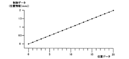
ここで、この実施例における所定のスケール特性の具体例を図8に示す。横軸が位置検出器12が出力する位置データを示し、たて軸が該位置データに対応して変換部15から発生される制御データを示す。この具体例では、所定のスケール特性として、位置検出器12が出力する位置データを、実位置にリニアに対応する値を持つ制御データに変換する例を示している。すなわち、この場合、制御データの値は、電動フェーダ10の操作位置にリニアに対応しており、実質的に位置情報と等価である。ただし、位置検出器12が出力する位置データは、そのセンサの位置検出精度によって所定の分解能に限定されるが、変換部15で出力する制御データ(位置情報)は、変換テーブル又は変換関数等の構成に応じて、センサ位置検出精度よりも細かな分解能のデータとして生成され得る。これによって、スケール変更特性において細かなデータ変換が可能である。
Here, a specific example of the predetermined scale characteristic in this embodiment is shown in FIG. The horizontal axis indicates the position data output from the
図8の例では、電動フェーダ10のつまみ11の位置に応じて、位置検出器12は0.1mmの分解能でデジタルの位置データを出力するものとしている。つまり、位置検出器12はつまみ11の0.1mm毎の変化に応じて1ポイントづつ増加するデジタルの位置データを出力する。図では、便宜上、横軸は20ポイントまでしか示されていないが、設計上適宜に定められるつまみ11の最大移動範囲に応じたポイント数からなる位置データが位置検出器12から出力される。そして、変換部15では、例えば、フェーダ10においてつまみ11が最下端にあるときの位置を0mm(基準位置=最小値)とし、つまみ11が最上端にあるときの位置をNmm(最大値)として、0.0mm(最小値)からN mm (最大値)までの位置情報をフェーダ位置検出情報(制御データ)として出力する。図では、便宜上、たて軸は2mmまでしか示されていないが、設計上適宜に定められるつまみ11の最大移動範囲に応じたNmm(最大値)までのフェーダ位置検出情報(制御データ)が変換部15から出力される。なお、変換部15が出力するフェーダ位置検出情報(制御データ)の値は、上記のような小数点第1位の.0mm単位(つまり、100μm単位)に限らず、小数点第2位の.00mm単位(つまり、10μm単位)あるいは小数点第3位の.000mm単位(つまり、1μm単位)など、設計上適宜に定めてよい。例えば、少なくともスケール変更特性においては細かな分解能でデータ変換を行うとよい。
In the example of FIG. 8, the
次に、図6に従ってリコールイベント処理(S13)の一例を説明する。
リコール指示があると、メモリからリコールすべきシーンの各パラメータ値(シーンデータ)を読み出し、これに基づき各電動フェーダ10の目標位置(Pt)を設定する(S21)。この場合、メモリに記憶されているシーンデータとして、位置検出器12が出力する位置データと同じスケールの目標位置データそのものを記憶している場合は、読み出したシーンデータに含まれる各電動フェーダ10のパラメータ値(つまり目標位置データ)そのものを目標位置データとして設定する。他方、メモリに記憶されているシーンデータとして、変換部15で所定のスケール特性に従って発生した制御データを記憶している場合は、読み出したシーンデータに含まれる各電動フェーダ10のパラメータ値(つまり制御データ)を、当該電動フェーダ10に対応する当該所定のスケール特性に従って位置データに逆変換したものを目標位置データとして設定する。設定された目標位置データは、前記目標位置レジスタに記憶される。なお、このステップS21は、図3のステップS1に対応している。
Next, an example of the recall event process (S13) will be described with reference to FIG.
When there is a recall instruction, each parameter value (scene data) of the scene to be recalled is read from the memory, and based on this, the target position (Pt) of each
ステップS22では、「スケール変更制御」の動作フラグを「TRUE」(1)にセットする。そして、各電動フェーダ10の目標位置を示すデータを対応するモータ制御部14にそれぞれ与え、それぞれのつまみ11を自動的に該目標位置まで移動させるよう、位置決め制御を行うべきことを指示する(S23)。この指示に応じて、モータ制御部14では、前述のとおり、指令された目標位置までつまみ11を自動的に動かし、位置決めが完了したら、位置決め完了信号をCPU101に返す。ステップS24では、位置決め完了信号を受けるまで待機する。位置決め完了すると、ステップS25で、そのとき位置検出器12から出力されている位置データ(実位置)を取得し、これを検出位置レジスタにストアする。この検出位置レジスタにストアされる実位置データは、目標位置(Pt)に対して実際に停止された位置(図2のPrに相当)を示しており、前述のように、−εまた+εの誤差を含み得る。一例として、−εまた+εの最大誤差範囲は、±0.5mm(位置検出器12が出力する位置データの単位で±5ポイント)であるとする。なお、ステップS24は図3のステップS2に対応し、ステップS25は図3のステップS3に対応している。
In step S22, the operation flag of “scale change control” is set to “TRUE” (1). Then, data indicating the target position of each
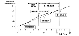
ステップS26では、図3のステップS4〜S5と同様に、目標位置レジスタにストアしている目標位置(Pt)と検出位置レジスタにストアしている検出位置(実際の停止位置Pr)に基づき、起点及び第1及び第2の変更区間を設定する。起点及び第1及び第2の変更区間の設定の仕方は、図2を参照して説明したのと同様であってよいが、ここで、より一層具体的な例につき図9を参照して説明する。 In step S26, as in steps S4 to S5 in FIG. 3, the starting point is based on the target position (Pt) stored in the target position register and the detection position (actual stop position Pr) stored in the detection position register. And the 1st and 2nd change area is set. The method of setting the starting point and the first and second change sections may be the same as described with reference to FIG. 2, but a more specific example will be described with reference to FIG. To do.
図9は、図8に示す所定のスケール特性に対する変更スケール特性の一例を示す図である。図9の例において、第1及び第2の変更区間の起点は、前述と同様に、目標位置Ptに対応するフェーダ位置検出情報(制御データ)が検出位置(実際の停止位置Pr)に対応して出力されるように設定する。図9の例において、第1の変更区間の終点1Eは、目標位置Ptを基準にして、所定の距離+Dの位置に設定する。ここで、Dは、位置決め誤差(−εまた+ε)の最大範囲E(例えば位置データの単位で5ポイント)に対して、D>Eであるように定める。あるいは、D=Eであってもよいが、変更スケール特性から所定のスケール特性に滑らかに移行させるには、D>Eが好ましい。また、第2の変更区間の終点2Eは、目標位置Ptを基準にして、所定の距離−Dの位置に設定する。すなわち、
1E:Pt+D
2E:Pt−D
である。これにより、目標位置Ptが必ず変更スケール特性の適用区間に含まれることになり、前述したような逆行が起こらず、また、第1及び第2の変更区間の長さを適切に確保することで、変更スケール特性から所定のスケール特性への移行を滑らかに行うことができる。
FIG. 9 is a diagram showing an example of the changed scale characteristic with respect to the predetermined scale characteristic shown in FIG. In the example of FIG. 9, the starting points of the first and second change sections are the same as described above, with the fader position detection information (control data) corresponding to the target position Pt corresponding to the detection position (actual stop position Pr). Set to be output. In the example of FIG. 9, the
1E: Pt + D
2E: Pt-D
It is. As a result, the target position Pt is always included in the application section of the change scale characteristic, the reverse as described above does not occur, and the lengths of the first and second change sections are appropriately secured. The transition from the changed scale characteristic to the predetermined scale characteristic can be performed smoothly.
ステップS27では、図3のステップS6と同様に、第1及び第2の変更区間に対応する第1及び第2の変更スケールを線形関数で設定し、設定した第1及び第2の変更スケールに従って位置データをフェーダ位置検出情報(制御データ)に変換するよう、変換部15に対して指示する。なお、この実施例の場合、変換部15の機能は図7の操作イベント処理(S15)によって実現される。例えば、下記式により、第1の変更区間に対応する第1の変更スケールの傾きA1と、第2の変更区間に対応する第2の変更スケールの傾きA2とが算出される。
A1=A×D/(1E−Pr)
A2=A×D/(Pr−2E)
ここで、Aは所定のスケール特性の関数F(x)の傾きである。
In step S27, as in step S6 of FIG. 3, first and second change scales corresponding to the first and second change sections are set by a linear function, and according to the set first and second change scales. The
A 1 = A × D / (1E-Pr)
A 2 = A × D / (Pr-2E)
Here, A is a slope of a function F (x) having a predetermined scale characteristic.
位置検出器12から出力される位置データをxで示し、初期値をBで示すと、線形関数からなる所定のスケール特性の関数F(x)は、
F(x)=Ax+B
と表わせる。
第1の変更区間に対応する第1の変更スケールを示す関数G1は、
G1(x)=A1x+(A−A1)1E+B
と表わせる。ただし、位置データxは第1の変更区間の範囲内の値。
第2の変更区間に対応する第2の変更スケールを示す関数G2は、
G2(x)=A2x+(A−A2)2E+B
と表わせる。ただし、位置データxは第2の変更区間の範囲内の値。
When the position data output from the
F (x) = Ax + B
It can be expressed as
The function G 1 indicating the first change scale corresponding to the first change section is
G 1 (x) = A 1 x + (A−A 1 ) 1E + B
It can be expressed as However, the position data x is a value within the range of the first change section.
The function G 2 indicating the second change scale corresponding to the second change section is
G 2 (x) = A 2 x + (A−A 2 ) 2E + B
It can be expressed as However, the position data x is a value within the range of the second change section.
図9の例の場合、D=6、B=0とし、
F(x)=(1/10)x+0
A1=(1/10)×6/(16−8)=3/40
A2=(1/10)×6/(8−4)=3/20
G1(x)=3/40x+(2/5)
G2(x)=3/20x−(1/5)
と表わせる。
In the case of the example of FIG. 9, D = 6, B = 0,
F (x) = (1/10) x + 0
A 1 = (1/10) × 6 / (16−8) = 3/40
A 2 = (1/10) × 6 / (8-4) = 3/20
G 1 (x) = 3 / 40x + (2/5)
G 2 (x) = 3 / 20x− (1/5)
It can be expressed as
なお、図6のステップS24〜S27の処理は、各フェーダ10毎にそれぞれ実行される。
Note that the processing in steps S24 to S27 in FIG. 6 is executed for each
次に、図7に従って操作イベント処理(S15)の一例を説明する。
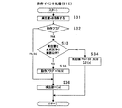
まず、シーンリコールの後、初めて当該電動フェーダ10が手動操作された場合について説明する。その場合、当該電動フェーダ10に関する「スケール変更制御」の動作フラグは「TRUE」であり(図6のS22)、変更スケール特性が適用されるモードであることを示している。ステップS31で、位置検出器12から出力される現在の位置データ(実位置x)を取得する。ステップS32で動作フラグを判定し、この場合は「TRUE」であるから、ステップS33に行く。ステップS33では、取得した実位置xが第1又は第2の変更区間の範囲外であるかを判定する。第1又は第2の変更区間の範囲内であれば、ステップS34に行き、第1又は第2の変更スケールを示す関数G1又はG2に従ってフェーダ位置検出情報(制御データ)を発生する。すなわち、実位置xが第1の変更区間内にあれば、該第1の変更区間に対応する第1の変更スケールを示す関数G1(x)に従ってフェーダ位置検出情報(制御データ)を発生し、実位置xが第2の変更区間内にあれば、該第2の変更区間に対応する第2の変更スケールを示す関数G2(x)に従ってフェーダ位置検出情報(制御データ)を発生する。以後、電動フェーダ10の操作イベントが発生する毎に、ステップS31,S32,S33,S34のルートの処理が行われ、第1又は第2の変更スケールを示す関数G1(x)又はG2(x)に従ってフェーダ位置検出情報(制御データ)を発生する。
Next, an example of the operation event process (S15) will be described with reference to FIG.
First, the case where the
やがて、電動フェーダ10の操作位置が第1又は第2の変更区間の範囲外に出ると、ステップS33はYESと判定し、ステップS35で動作フラグを「FALSE」にリセットする。こうして、変更スケール特性を適用するモードを解除する。次のステップS36では、所定のスケール特性を示す通常の関数F(x)に従って実位置xに応じたフェーダ位置検出情報(制御データ)を発生する。以後は、ステップS32で、動作フラグは「FALSE」と判定され、図7の処理は、S31,S32,S36のルートを通る。従って、以後は、電動フェーダ10の操作イベントが発生する毎に、所定のスケール特性を示す通常の関数F(x)に従って実位置xに応じたフェーダ位置検出情報(制御データ)を発生する。
Eventually, when the operation position of the
図9を例にして具体的に説明すると、目標位置Ptとして10ポイント(1mm)の位置が指定され、自動位置決めの結果、フェーダ10のつまみ11は、実際には8ポイント(0.8mm)の位置Prで停止している。目標位置からのずれは2ポイント(0.2mm)であり、所定の最大誤差±E=±0.5mm(±5ポイント)の範囲内である。その後、フェーダ10が増加方向に手動で動かされたとすると、第1の変更区間に対応する第1の変更スケールを示す関数G1(x)が適用され、起点における実位置xは位置Pr(8ポイント)であるが、それに対応するフェーダ位置検出情報(制御データ)として、所定のスケール特性上の目標位置Pt(10ポイント)に対応する1.0mmを示すフェーダ位置検出情報(制御データ)が発生される。以後、第1の変更区間においては、実位置xの8〜16ポイントの変化に対して、第1の変更スケールを示す関数G1(x)に従って、1.0mm〜1.6mmのフェーダ位置検出情報(制御データ)が発生される。そして、終点1E=16ポイントを過ぎて、第1の変更区間の外に出ると、所定のスケール特性を示す関数F(x)に従ってフェーダ位置検出情報(制御データ)が発生されるようになる。なお、この場合、1.00mm〜1.60mmあるいは1.000mm〜1.600mmのように、小数点の有効桁を増すことで細かな分解能でフェーダ位置検出情報(制御データ)を発生するようにすれば、図示のような滑らかな変化を得ることができる。一方、1.0mm〜1.6mmのように、有効桁が小数点第1位であると、必ずしも図示のような滑らかな変化とはならず、幾分階段状となるが、それでも差し支えない。
Specifically, taking FIG. 9 as an example, a position of 10 points (1 mm) is designated as the target position Pt, and as a result of automatic positioning, the
一方、起点(Pr)からフェーダ10が減少方向に手動で動かされたとすると、第2の変更区間に対応する第2の変更スケールを示す関数G2(x)が適用され、実位置xの8〜4ポイントの変化に対して、第2の変更スケールを示す関数G2(x)に従って、1.0mm〜0.4mmのフェーダ位置検出情報(制御データ)が発生される。そして、終点2E=4ポイントを過ぎて、第2の変更区間の外に出ると、所定のスケール特性を示す関数F(x)に従ってフェーダ位置検出情報(制御データ)が発生されるようになる。
On the other hand, if the
勿論、一旦、第1又は第2の変更区間の外に出ると、変更スケール特性の適用が解除されるので、以後は、第1又は第2の変更区間であった区間内に操作位置が戻されたとしても、所定のスケール特性を示す関数F(x)に従ってフェーダ位置検出情報(制御データ)が発生される。 Of course, once outside the first or second change section, the application of the change scale characteristic is canceled, and thereafter the operation position returns to the section that was the first or second change section. Even if it is done, fader position detection information (control data) is generated according to a function F (x) indicating a predetermined scale characteristic.
図10は、図8に示す所定のスケール特性に対する変更スケール特性の別の例を示す図である。図10の例は、第1及び第2の変更区間の終点1E,2Eの定め方が図9の例とは相違している。図10の例において、第1の変更区間の終点1Eは、目標位置に対する実際の停止位置Prを基準にして所定の距離+Dの位置に設定し、また、第2の変更区間の終点2Eは、目標位置に対する実際の停止位置Prを基準にして所定の距離−Dの位置に設定する。ここで、Dは、位置決め誤差(−εまた+ε)の最大範囲E(例えば位置データの単位で5ポイント)に対して、D=Eであるように定めている。D>Eであってもよく、変更スケール特性から所定のスケール特性に滑らかに移行させるには、むしろD>Eの方が好ましい。D=Eの場合は、位置決め誤差(−εまた+ε)が最大値Eのとき、第1又は第2の変更区間の一方の変更スケールの傾きがフラットになるが、D>Eの場合はそれを避けることができる。
FIG. 10 is a diagram showing another example of the changed scale characteristic with respect to the predetermined scale characteristic shown in FIG. The example of FIG. 10 is different from the example of FIG. 9 in how to determine the
ところで、フェーダ10の所定移動範囲の両端部においては、それぞれの端部の近傍に起点が位置する場合、前記第1及び第2の変更区間の一方(端部寄りの変更区間)の終点1E又は2Eを適切に設定することができず、該一方の変更区間に関しては適切な変更スケールの設定ができなくなる。このような端部問題を解決するためには、次のような2種の対策が考えられる。
By the way, at both ends of the predetermined movement range of the
一つの対策としては、図11に示すように、変換部15において設定する前記所定のスケール特性において、フェーダ10の最大移動範囲の両端部の所定範囲Dにおける位置データ(横軸)の変化に対して制御データ(たて軸)の最小値及び最大値を維持するマージン領域M1,M2をそれぞれ設定することである。この場合、フェーダ10はマージン領域M1,M2に入って動かすことができるが、有効な制御データを得ることができる有効操作範囲は、マージン領域M1,M2の内側である。このマージン領域M1,M2の所定範囲(幅)Dは、少なくとも位置決め誤差(−εまた+ε)の最大範囲Eに等しくする(D=E)。つまり、目標位置(Pt)が最小値又は最大値のとき、最大の位置決め誤差(マージン領域M1側では−ε、マージン領域M2側では+ε)で位置決めされた停止位置(Pr)がマージン領域M1,M2に含まれるようにする。
As one countermeasure, as shown in FIG. 11, in the predetermined scale characteristic set in the
そして、スケール変更制御部16では、前記第1の変更区間の前記起点が前記マージン領域M1,M2に入る場合は、前記第1の変更区間についてのみ前記第1の変更スケールに従う前記制御データの発生を行うようにする。このようにすれば、起点(Pr)がマージン領域M1,M2に入る場合、目標位置(Pt)とは反対側の第2の変更区間に対応する所定のスケール特性は全てマージン領域M1,M2に入ることとなり、一定の最小値又は最大値を維持すればよい(若しくは有効なデータを発生する必要がない)こととなる。従って、その終点2Eを適切に設定することができなかったとしても、適切な変更スケールの設定が行える(一定の最小値又は最大値を維持すればよいため)、若しくは、その部分では有効なデータを発生する必要がないものとなる。
Then, the scale
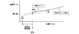
別の対策としては、図12に示すように、フェーダ10の移動範囲の両端部(図12では一端部ESの側のみ拡大して示している)において、該各端部(ES)を越える仮想的な位置検出領域をそれぞれ設定し、該各端部(ES)における前記第2の変更区間を前記仮想的な位置検出領域にわたって設定するようにする。仮想的な位置検出領域とは、フェーダ10の移動範囲外であるため、その領域に対応する位置データ(x)は実際には発生されないが、位置データ(x)が発生されると仮定して所定のスケール特性に従うフェーダ位置検出情報(制御データ)を仮想的に生成できるようにした領域である。この仮想的な位置検出領域を設定することにより、第2の変換区間の終点2Eが設定できるようになり、第2の変換スケールを示す関数G2(x)を設定・演算することができる。
As another countermeasure, as shown in FIG. 12, at both ends of the movement range of the fader 10 (in FIG. 12, only the one end ES side is enlarged), the virtual exceeding each end (ES) is shown. A specific position detection area is set, and the second change section at each end (ES) is set over the virtual position detection area. Since the virtual position detection area is outside the movement range of the
なお、図8に示すように変換部15における所定のスケール特性がリニア関数である場合において、最終的な制御データ(パラメータ)として、フェーダ10の移動量に対してデシベル特性等の非リニアな関数特性を示すデータ(パラメータ)を得たいならば、変換部15から出力されるフェーダ位置検出情報(制御データ)を所望の非リニアな変換特性の変換手段で更に変換するようにすればよい。勿論、それに限らず、変換部15における所定のスケール特性そのものを、所望の非リニアな変換特性としてもよく、その場合は、変換部15から発生されるフェーダ位置検出情報(制御データ)が直接的にデシベル(減衰量)データ等の所定のスケール特性のデータで表現される。
As shown in FIG. 8, when the predetermined scale characteristic in the
本発明を適用しうる操作子は、上記実施例のようなフェーダ(スライド式又はリニア式に移動する操作子)に限らず、回転式の操作子あるいはその他の形式の操作子であってもよく、要は手動操作と自動操作のどちらもが可能なように構成されたものであればよい。 The operation element to which the present invention can be applied is not limited to a fader (an operation element that moves in a slide type or linear type) as in the above embodiment, but may be a rotary operation element or other types of operation elements. In short, it may be anything that is configured so that both manual operation and automatic operation are possible.
位置検出器12から出力される位置データの分解能とこれに応じて変換部15から出力されるフェーダ位置検出情報(制御データ)の値との対応関係は、上記のように所定のスケール特性がリニア特性又は非リニア特性のどちらであるにせよ、連続的に対応付けられるようになっていてもよいし、あるいは、不連続的またステップ状に対応付けられるようになっていてもよい。
The correspondence between the resolution of the position data output from the
本発明に係る制御データ発生装置(電動フェーダ10)は、上記のようなミキサ装置に限らず、電子楽器、アミューズメント機器、電子玩具、その他の各種制御機器などにおいても適用することができる。 The control data generation device (electric fader 10) according to the present invention is not limited to the mixer device as described above, but can be applied to an electronic musical instrument, an amusement device, an electronic toy, and other various control devices.
10 電動フェーダ
11 スライド式つまみ(操作子)
12 位置検出器
13 駆動機
14 モータ制御部
15 変換部
16 スケール変更制御部
100 電動フェーダ部
101 CPU
10
12
Claims (7)
前記所定移動範囲における前記操作子の現操作位置に応じた位置データを出力する位置検出手段と、
前記位置検出手段で検出した位置データを所定のスケール特性で制御データに変換する変換手段と、
指令された目標位置に前記操作子を位置決めする自動位置決め手段であって、この自動位置決め手段による位置決め精度は前記位置検出手段による位置検出精度よりも粗く、そのため、前記位置検出手段による位置検出精度に対して所定の誤差範囲内で前記目標位置への位置決めが行われる前記自動位置決め手段と、
前記自動位置決め手段による位置決め完了時において変更スケール特性を適用するスケール変更制御手段であって、
該変更スケール特性においては、前記位置決め完了時において前記位置検出手段から出力される位置データに対応して前記所定のスケール特性上の前記目標位置に対応する制御データが出力されるように起点を設定すると共に、前記起点の位置から少なくとも前記目標位置に達するまでの区間を含む第1の変更区間を設定し、前記位置検出手段から出力される位置データに対応する前記制御データが、前記起点に対応する制御データから該第1の変更区間の終点の位置に対応する前記所定のスケール特性上の制御データまで第1の変更スケールに従って漸次変化するように変更し、
前記操作子の位置が前記第1の変更区間の終点に達したならば前記変更スケール特性の適用を解除する前記スケール変更制御手段と
備える制御データ発生装置。 An operator operable over a predetermined movement range;
Position detecting means for outputting position data corresponding to the current operation position of the operating element in the predetermined movement range;
Conversion means for converting the position data detected by the position detection means into control data with a predetermined scale characteristic;
Automatic positioning means for positioning the operating element at a commanded target position, and the positioning accuracy by the automatic positioning means is coarser than the position detection accuracy by the position detection means, and therefore the position detection accuracy by the position detection means The automatic positioning means for positioning to the target position within a predetermined error range,
Scale change control means for applying a change scale characteristic at the completion of positioning by the automatic positioning means,
In the changed scale characteristic, the starting point is set so that the control data corresponding to the target position on the predetermined scale characteristic is output corresponding to the position data output from the position detecting means when the positioning is completed. In addition, a first change section including a section from the position of the starting point to at least the target position is set, and the control data corresponding to the position data output from the position detecting unit corresponds to the starting point. From the control data to the control data on the predetermined scale characteristic corresponding to the position of the end point of the first change section to change gradually according to the first change scale,
A control data generating device provided with the scale change control means for canceling the application of the changed scale characteristic when the position of the operator reaches the end point of the first change section.
前記第1の変更区間の前記起点が前記マージン領域に入る場合は、前記第1の変更区間についてのみ前記第1の変更スケールに従う前記制御データの発生を行うようにしたことを特徴とする請求項1乃至3のいずれかに記載の制御データ発生装置。 The conversion means sets a margin area for maintaining a minimum value or a maximum value of control data with respect to a change in position data of a predetermined range at both ends of the predetermined movement range in the predetermined scale characteristic
The control data according to the first change scale is generated only for the first change section when the starting point of the first change section enters the margin area. The control data generator according to any one of 1 to 3.
前記位置検出手段で検出した位置データを所定のスケール特性で制御データに変換する第1手順と、
前記自動位置決め手段による位置決め完了時において変更スケール特性を適用する第2手順であって、
該変更スケール特性においては、前記位置決め完了時において前記位置検出手段から出力される位置データに対応して前記所定のスケール特性上の前記目標位置に対応する制御データが出力されるように起点を設定すると共に、前記起点の位置から少なくとも前記目標位置に達するまでの区間を含む第1の変更区間を設定し、前記位置検出手段から出力される位置データに対応する前記制御データが、前記起点に対応する制御データから該第1の変更区間の終点の位置に対応する前記所定のスケール特性上の制御データまで第1の変更スケールに従って漸次変化するように変更し、
前記操作子の位置が前記第1の変更区間の終点に達したならば前記変更スケール特性の適用を解除する前記第2手順と
実行させるためのプログラム。 An operation element operable over a predetermined movement range, position detecting means for outputting position data corresponding to the current operation position of the operation element in the predetermined movement range, and automatic positioning for positioning the operation element at a commanded target position The positioning accuracy by the automatic positioning unit is coarser than the position detection accuracy by the position detection unit. Therefore, the positioning to the target position is within a predetermined error range with respect to the position detection accuracy by the position detection unit. In the operating device provided with the automatic positioning means, a program for generating control data, the computer,
A first procedure for converting position data detected by the position detection means into control data with a predetermined scale characteristic;
A second procedure for applying the modified scale characteristic at the completion of positioning by the automatic positioning means,
In the changed scale characteristic, the starting point is set so that the control data corresponding to the target position on the predetermined scale characteristic is output corresponding to the position data output from the position detecting means when the positioning is completed. In addition, a first change section including a section from the position of the starting point to at least the target position is set, and the control data corresponding to the position data output from the position detecting unit corresponds to the starting point. From the control data to the control data on the predetermined scale characteristic corresponding to the position of the end point of the first change section to change gradually according to the first change scale,
A program for executing the second procedure for canceling the application of the change scale characteristic when the position of the operation element reaches the end point of the first change section.
Priority Applications (4)
| Application Number | Priority Date | Filing Date | Title |
|---|---|---|---|
| JP2008202922A JP5083108B2 (en) | 2008-08-06 | 2008-08-06 | Control data generator |
| AT09167338T ATE527659T1 (en) | 2008-08-06 | 2009-08-06 | CONTROL DATA GENERATION APPARATUS AND METHOD |
| EP09167338A EP2151825B1 (en) | 2008-08-06 | 2009-08-06 | Control data generation device and method |
| US12/536,716 US8923533B2 (en) | 2008-08-06 | 2009-08-06 | Control data generation device and method |
Applications Claiming Priority (1)
| Application Number | Priority Date | Filing Date | Title |
|---|---|---|---|
| JP2008202922A JP5083108B2 (en) | 2008-08-06 | 2008-08-06 | Control data generator |
Publications (2)
| Publication Number | Publication Date |
|---|---|
| JP2010039820A true JP2010039820A (en) | 2010-02-18 |
| JP5083108B2 JP5083108B2 (en) | 2012-11-28 |
Family
ID=41170112
Family Applications (1)
| Application Number | Title | Priority Date | Filing Date |
|---|---|---|---|
| JP2008202922A Expired - Fee Related JP5083108B2 (en) | 2008-08-06 | 2008-08-06 | Control data generator |
Country Status (4)
| Country | Link |
|---|---|
| US (1) | US8923533B2 (en) |
| EP (1) | EP2151825B1 (en) |
| JP (1) | JP5083108B2 (en) |
| AT (1) | ATE527659T1 (en) |
Cited By (2)
| Publication number | Priority date | Publication date | Assignee | Title |
|---|---|---|---|---|
| JP2015036917A (en) * | 2013-08-14 | 2015-02-23 | キヤノン株式会社 | Method and device for alignment |
| CN106681368A (en) * | 2015-08-07 | 2017-05-17 | 雅马哈株式会社 | Electric Fader Drive Unit, Fader Device, and Audio Mixer |
Families Citing this family (7)
| Publication number | Priority date | Publication date | Assignee | Title |
|---|---|---|---|---|
| EP2369766A3 (en) * | 2010-03-26 | 2015-07-08 | Yamaha Corporation | Mixer |
| WO2011125357A1 (en) * | 2010-04-02 | 2011-10-13 | 株式会社安川電機 | Encoder, drive device, absolute position calculation method, and encoder manufacturing method |
| JP5605186B2 (en) * | 2010-11-23 | 2014-10-15 | アイシン・エィ・ダブリュ株式会社 | Control device, control method of control device, and computer program |
| US9196236B1 (en) * | 2014-09-02 | 2015-11-24 | Native Instruments Gmbh | Electronic music instrument, system and method for operating an electronic music instrument |
| JP6623608B2 (en) * | 2015-08-07 | 2019-12-25 | ヤマハ株式会社 | Electric fader driving device and electric fader driving program |
| WO2017156271A1 (en) * | 2016-03-11 | 2017-09-14 | Sound Devices, LLC | Magnetic linear fader |
| US10055034B2 (en) | 2016-06-27 | 2018-08-21 | Google Llc | Haptic feedback system |
Citations (3)
| Publication number | Priority date | Publication date | Assignee | Title |
|---|---|---|---|---|
| JP2684808B2 (en) * | 1990-03-09 | 1997-12-03 | ヤマハ株式会社 | Motor control of motor-driven knob |
| JP2004102569A (en) * | 2002-09-09 | 2004-04-02 | Yamaha Corp | Electric fader drive unit |
| JP2004178395A (en) * | 2002-11-28 | 2004-06-24 | Yamaha Corp | Operating element location detection device and operating element location control device |
Family Cites Families (12)
| Publication number | Priority date | Publication date | Assignee | Title |
|---|---|---|---|---|
| JP2630651B2 (en) * | 1989-07-26 | 1997-07-16 | ヤマハ株式会社 | Fader device |
| JPH07101827B2 (en) * | 1989-10-13 | 1995-11-01 | ヤマハ株式会社 | Mixing console |
| US5243513A (en) * | 1991-04-23 | 1993-09-07 | Peters John M | Automation control with improved operator/system interface |
| GB2269056B (en) * | 1992-07-20 | 1996-06-05 | Sony Corp | Linear control arrangements |
| US5805146A (en) * | 1993-11-05 | 1998-09-08 | Intertactile Technologies Corporation | Integrated display screen and slidable control for electrical circuits |
| DE4438793C2 (en) * | 1994-10-18 | 1997-02-13 | Stage Tec Gmbh | Method for recognizing a manual intervention in devices for setting electrical signals in control systems and device for implementing the method |
| JP3522446B2 (en) * | 1996-05-15 | 2004-04-26 | 松下電器産業株式会社 | Fader control device |
| JP3772802B2 (en) * | 2002-07-02 | 2006-05-10 | ヤマハ株式会社 | Volume setting operator drive device |
| US7319765B2 (en) * | 2002-09-06 | 2008-01-15 | Yamaha Corporation | Parameter setting device |
| JP4192757B2 (en) * | 2003-10-30 | 2008-12-10 | ヤマハ株式会社 | Digital mixer and control method thereof |
| JP4943670B2 (en) * | 2005-06-09 | 2012-05-30 | ヤマハ株式会社 | Mixer device and channel parameter setting change program in mixer |
| JP5028931B2 (en) * | 2006-09-28 | 2012-09-19 | ヤマハ株式会社 | Parameter setting device |
-
2008
- 2008-08-06 JP JP2008202922A patent/JP5083108B2/en not_active Expired - Fee Related
-
2009
- 2009-08-06 US US12/536,716 patent/US8923533B2/en not_active Expired - Fee Related
- 2009-08-06 EP EP09167338A patent/EP2151825B1/en not_active Not-in-force
- 2009-08-06 AT AT09167338T patent/ATE527659T1/en not_active IP Right Cessation
Patent Citations (3)
| Publication number | Priority date | Publication date | Assignee | Title |
|---|---|---|---|---|
| JP2684808B2 (en) * | 1990-03-09 | 1997-12-03 | ヤマハ株式会社 | Motor control of motor-driven knob |
| JP2004102569A (en) * | 2002-09-09 | 2004-04-02 | Yamaha Corp | Electric fader drive unit |
| JP2004178395A (en) * | 2002-11-28 | 2004-06-24 | Yamaha Corp | Operating element location detection device and operating element location control device |
Cited By (2)
| Publication number | Priority date | Publication date | Assignee | Title |
|---|---|---|---|---|
| JP2015036917A (en) * | 2013-08-14 | 2015-02-23 | キヤノン株式会社 | Method and device for alignment |
| CN106681368A (en) * | 2015-08-07 | 2017-05-17 | 雅马哈株式会社 | Electric Fader Drive Unit, Fader Device, and Audio Mixer |
Also Published As
| Publication number | Publication date |
|---|---|
| ATE527659T1 (en) | 2011-10-15 |
| JP5083108B2 (en) | 2012-11-28 |
| US20100034400A1 (en) | 2010-02-11 |
| US8923533B2 (en) | 2014-12-30 |
| EP2151825B1 (en) | 2011-10-05 |
| EP2151825A1 (en) | 2010-02-10 |
Similar Documents
| Publication | Publication Date | Title |
|---|---|---|
| JP5083108B2 (en) | Control data generator | |
| JP3773049B2 (en) | A musical tone attenuation rate control device that generates decibel linear attenuation rate data according to the position of the knob. | |
| JP5750671B1 (en) | Imaging device | |
| US9261667B2 (en) | Driving device, projector, and driving method | |
| JP4918789B2 (en) | Parameter setting device and program | |
| JPH07244534A (en) | Adjustment of transformer, which parameterizes digital voltage regulator and especially has on-load tap changer | |
| JPH0778007A (en) | Analog signal processor for programmable controller | |
| EP2852056B1 (en) | Quantity adjusting apparatus | |
| JP5077816B2 (en) | Acoustic equipment with touch panel | |
| JP4101085B2 (en) | Parameter setting device | |
| US7732701B2 (en) | Electronic musical instrument | |
| KR20200076975A (en) | Apparatus for setting drive mode and method threrof | |
| JP2017175456A (en) | Signal processing apparatus | |
| JP3409865B2 (en) | Tempo setting device | |
| JP7187219B2 (en) | Operating device, optical device, and imaging device | |
| JP4893666B2 (en) | Parameter setting device and program | |
| JPH05241662A (en) | Servo motor controller | |
| JPH0746066A (en) | Digital volume | |
| JP2002112566A (en) | Motor controller | |
| JPH07253781A (en) | Electronic musical instrument | |
| JP2006220849A (en) | Analog meter type tuning instrument and pointer correction method therefor | |
| JP5532524B2 (en) | Acoustic device with touch panel, channel selection device, and program | |
| JP2005192136A (en) | Mixing apparatus | |
| JP4694238B2 (en) | Servo motor control device | |
| JP5095671B2 (en) | Input device |
Legal Events
| Date | Code | Title | Description |
|---|---|---|---|
| A621 | Written request for application examination |
Free format text: JAPANESE INTERMEDIATE CODE: A621 Effective date: 20110620 |
|
| A977 | Report on retrieval |
Free format text: JAPANESE INTERMEDIATE CODE: A971007 Effective date: 20120725 |
|
| TRDD | Decision of grant or rejection written | ||
| A01 | Written decision to grant a patent or to grant a registration (utility model) |
Free format text: JAPANESE INTERMEDIATE CODE: A01 Effective date: 20120807 |
|
| A01 | Written decision to grant a patent or to grant a registration (utility model) |
Free format text: JAPANESE INTERMEDIATE CODE: A01 |
|
| A61 | First payment of annual fees (during grant procedure) |
Free format text: JAPANESE INTERMEDIATE CODE: A61 Effective date: 20120820 |
|
| R150 | Certificate of patent or registration of utility model |
Free format text: JAPANESE INTERMEDIATE CODE: R150 |
|
| FPAY | Renewal fee payment (event date is renewal date of database) |
Free format text: PAYMENT UNTIL: 20150914 Year of fee payment: 3 |
|
| LAPS | Cancellation because of no payment of annual fees |