JP2010032944A - Projection display device - Google Patents
Projection display device Download PDFInfo
- Publication number
- JP2010032944A JP2010032944A JP2008197320A JP2008197320A JP2010032944A JP 2010032944 A JP2010032944 A JP 2010032944A JP 2008197320 A JP2008197320 A JP 2008197320A JP 2008197320 A JP2008197320 A JP 2008197320A JP 2010032944 A JP2010032944 A JP 2010032944A
- Authority
- JP
- Japan
- Prior art keywords
- light
- display device
- light sources
- projection display
- cooling
- Prior art date
- Legal status (The legal status is an assumption and is not a legal conclusion. Google has not performed a legal analysis and makes no representation as to the accuracy of the status listed.)
- Pending
Links
Images


Classifications
-
- G—PHYSICS
- G03—PHOTOGRAPHY; CINEMATOGRAPHY; ANALOGOUS TECHNIQUES USING WAVES OTHER THAN OPTICAL WAVES; ELECTROGRAPHY; HOLOGRAPHY
- G03B—APPARATUS OR ARRANGEMENTS FOR TAKING PHOTOGRAPHS OR FOR PROJECTING OR VIEWING THEM; APPARATUS OR ARRANGEMENTS EMPLOYING ANALOGOUS TECHNIQUES USING WAVES OTHER THAN OPTICAL WAVES; ACCESSORIES THEREFOR
- G03B21/00—Projectors or projection-type viewers; Accessories therefor
- G03B21/14—Details
- G03B21/16—Cooling; Preventing overheating
Abstract
Description
本発明は、発光体としての光源を冷却する冷却手段を備えたプロジェクター等の投写型表示装置に関し、特に複数の光源を使用した投写型表示装置において、光源を適切に冷却できる投写型表示装置の技術に係るものである。 The present invention relates to a projection display device such as a projector provided with a cooling means for cooling a light source as a light emitter, and more particularly to a projection display device that can appropriately cool a light source in a projection display device using a plurality of light sources. It relates to technology.
従来、大画面の映像を得るための装置として、DMD(Digital Micromirror Device)や液晶等の画像表示デバイスを使って光源ランプからの光を映像信号で変調して光学像を形成して照射し、投写レンズによりスクリーン上に拡大投写するプロジェクター等の投写型表示装置が知られている。 Conventionally, as an apparatus for obtaining a large screen image, an image display device such as a DMD (Digital Micromirror Device) or a liquid crystal is used to modulate light from a light source lamp with a video signal to form an optical image and irradiate it. 2. Description of the Related Art Projection display devices such as projectors that perform enlarged projection on a screen using a projection lens are known.
光源ランプ内には、水銀、希ガス、ハロゲン化金属等が封入されており、光源ランプの電極に所定の電圧を印加すると、放電アークが発生し、内部に封入されているガスが対流する。放電アークは封入ガスの対流により山なりのアーチ状になり、光源ランプの上部に近づき、光源ランプ上部の温度が上昇する。光源ランプの温度が過度に上昇すると、白化、寿命の低下等が発生し、逆に光源ランプの温度が低すぎる場合には、黒化や光源の輝度の低下等が発生する原因となる。したがって、光源の温度管理の良否が、投写型表示装置の品質および信頼性に重要な影響を与えることとなる。 Mercury, rare gas, metal halide, and the like are enclosed in the light source lamp, and when a predetermined voltage is applied to the electrode of the light source lamp, a discharge arc is generated, and the gas enclosed inside convects. The discharge arc becomes a mountain-like arch shape by the convection of the filled gas, approaches the upper part of the light source lamp, and the temperature of the upper part of the light source lamp rises. If the temperature of the light source lamp rises excessively, whitening, a decrease in life, and the like occur, and conversely, if the temperature of the light source lamp is too low, blackening and a decrease in luminance of the light source occur. Therefore, the quality control of the light source has an important influence on the quality and reliability of the projection display device.
特に、高輝度な投写画像を実現する目的で複数の光源を使用した装置(例えば、特許文献1、2参照)では、一つの光源に不具合が発生して不点灯となった場合でも、他の光源の点灯が維持されれば、投写画像が途切れないという利点がある反面、光源の点灯に係わる条件が複雑になるという新たな課題が発生する。特に、複数の光源の相互の影響を含めた光源の温度管理についての検討が重要であるが、従来、光源の温度管理については、単一の光源に関する冷却ファンの制御方法ついての開示例に止まっている(例えば、特許文献3参照)。
しかしながら、複数の光源を使用し、それぞれの光源からの出力光を合成して表示デバイスに照射し、映像を投写する場合には、合成されて有効光として使用される出力光の有効成分のほかに、散逸または不要な照射を行う無効成分があることに注意しなければならない。例えば、複数の光源からの出力光を合成する装置において、出力光の一部は有効光とならず対向する光源を照射し、照射された光源の温度を上昇させる。これが光源の白化、寿命の低下等の問題を発生させる原因となる。 However, when using multiple light sources, combining the output light from each light source and irradiating the display device to project an image, in addition to the effective components of the output light that are combined and used as effective light Note that there are ineffective components that dissipate or cause unwanted irradiation. For example, in an apparatus that synthesizes output light from a plurality of light sources, a part of the output light does not become effective light, but irradiates an opposing light source to raise the temperature of the irradiated light source. This causes problems such as whitening of the light source and a decrease in life.
本発明は、このような課題を解決するものであり、複数の光源を使用した投写型表示装置において、光源の温度管理に関し高精度で確実な制御を可能にすることにより、光源の白化、寿命の低下、黒化、輝度低下などを抑制し、高品質で信頼性の高い投写型表示装置を実現することを目的とする。 The present invention solves such a problem, and in a projection display device using a plurality of light sources, by enabling highly accurate and reliable control regarding the temperature management of the light sources, the whitening and lifetime of the light sources can be achieved. An object of the present invention is to realize a high-quality and highly reliable projection display device that suppresses a decrease in brightness, blackening, brightness reduction, and the like.
上述の目的を達成するために、本発明の投写型表示装置は、複数の光源と、表示デバイスと、複数の光源の出力光を合成する光合成手段と、光合成手段の出力光を表示デバイスに伝搬する集光手段と、表示デバイスの出力光により映像を投写する投写手段とを備えた投写型表示装置であって、複数の光源にそれぞれ配設されたファンを備えた冷却手段と、冷却手段を制御する制御手段とを備え、制御手段は、複数の光源の点灯状況に関する情報に基づき、冷却手段のファンの回転数を制御することを特徴とする。 In order to achieve the above object, a projection display apparatus according to the present invention includes a plurality of light sources, a display device, a light combining unit that combines output lights from the plurality of light sources, and a light output from the light combining unit to the display device. A projection-type display apparatus comprising: a light collecting means for performing projection; and a projection means for projecting an image by output light of a display device, wherein the cooling means includes a fan disposed in each of a plurality of light sources, and the cooling means. Control means for controlling, and the control means controls the number of rotations of the fan of the cooling means based on information relating to lighting conditions of a plurality of light sources.
このような構成により、複数の光源の点灯状況に関する情報に基づき、複数の光源にそれぞれ配設された冷却手段のファンの回転数を制御することが可能となる。したがって、複数の光源それぞれの点灯状況に関する情報に基づいて冷却手段の冷却効果を制御し、それぞれの光源の発熱に対して適切な冷却を行うことができる。これにより、光源の白化、寿命の低下等を防止すると共に、黒化や輝度低下を防止することが可能となり、信頼性の高い投射型表示装置を実現することができる。 With such a configuration, it is possible to control the rotational speeds of the fans of the cooling means respectively disposed on the plurality of light sources based on information on the lighting status of the plurality of light sources. Therefore, it is possible to control the cooling effect of the cooling means based on the information regarding the lighting status of each of the plurality of light sources, and to perform appropriate cooling with respect to the heat generation of each light source. As a result, it is possible to prevent whitening of the light source, a decrease in lifetime, and the like, as well as prevention of blackening and luminance reduction, and a highly reliable projection display device can be realized.
また、本発明の投写型表示装置では、複数の光源は少なくとも一組の対向する光源を含み、制御手段は、対向する光源の点灯状況に関する情報に基づき、対向する光源に配設された冷却手段の駆動電圧を制御し、冷却手段のファンの回転数を制御する。 In the projection display device of the present invention, the plurality of light sources include at least one pair of opposing light sources, and the control means is a cooling means disposed on the opposing light sources based on information on the lighting status of the opposing light sources. And the number of rotations of the fan of the cooling means is controlled.
このような構成により、対向する光源の点灯状況に関する情報に基づき、それぞれの光源に配設された冷却手段の駆動電圧を制御し、冷却手段のファンの回転数を制御することが可能となる。したがって、対向する光源の点灯状況に関する情報に基づいて冷却手段の冷却効果を制御し、例えば、対向する光源が共に点灯する場合には冷却手段の冷却効果を高めるなど、対向する光源の発熱に対して適切な冷却を行うことができる。これにより、光源の劣化や寿命低下などを発生しにくい信頼性の高い投射型表示装置を実現することができる。 With such a configuration, it is possible to control the driving voltage of the cooling means disposed in each light source based on the information regarding the lighting status of the opposing light sources, and to control the rotation speed of the fans of the cooling means. Therefore, the cooling effect of the cooling means is controlled based on the information on the lighting status of the opposing light sources. For example, when both opposing light sources are lit, the cooling effect of the cooling means is enhanced. Therefore, proper cooling can be performed. Thereby, it is possible to realize a highly reliable projection type display device that is unlikely to cause deterioration of the light source or a reduction in lifetime.
また、本発明の投写型表示装置では、冷却手段のファンの回転数を検知する回転検知手段を更に備え、回転検知手段から出力される情報に基づき、冷却手段のファンの回転数を所定の回転数に制御する。このような構成により、回転検知手段により冷却手段のファンの回転数を検知して、冷却手段のファンの回転数を所定の回転数に制御することが可能となり、冷却手段の回転数の制御を正確かつ確実に行うことができる。 The projection display apparatus of the present invention further includes a rotation detection unit that detects the rotation number of the fan of the cooling unit, and sets the rotation number of the fan of the cooling unit to a predetermined rotation based on information output from the rotation detection unit. Control to number. With this configuration, it is possible to detect the rotational speed of the fan of the cooling means by the rotation detecting means and control the rotational speed of the fan of the cooling means to a predetermined rotational speed, and control the rotational speed of the cooling means. It can be done accurately and reliably.
また、本発明の投写型表示装置では、気温検出手段、気圧検出手段および設置姿勢検出手段を更に備え、気温検出手段、気圧検出手段および設置姿勢検出手段から出力された情報、ならびに複数の光源の点灯状況に関する情報に基づき、冷却手段のファンの回転数を制御する。このような構成により、光源の点灯状況に関する情報に加え、気温検出手段、気圧検出手段および設置姿勢検出手段から出力された情報に基づいて冷却手段のファンの回転数を制御することが可能となる。したがって、投写型表示装置の設置に関し、設置場所の温度や、高度、垂直・水平の設置姿勢を冷却手段の制御要件とすることができる。これにより、冷却手段の制御品質および冷却効率を高め、光源に対して更に確実かつ適切な冷却を行うことができる。 The projection display apparatus of the present invention further includes an air temperature detecting means, an atmospheric pressure detecting means, and an installation posture detecting means, and information output from the air temperature detecting means, the atmospheric pressure detection means, and the installation posture detecting means, and a plurality of light sources. Based on the information on the lighting status, the number of rotations of the fan of the cooling means is controlled. With such a configuration, it becomes possible to control the rotation speed of the fan of the cooling means based on the information output from the temperature detecting means, the atmospheric pressure detecting means, and the installation posture detecting means in addition to the information related to the lighting state of the light source. . Therefore, regarding the installation of the projection display device, the temperature of the installation location, the altitude, and the vertical and horizontal installation postures can be the control requirements of the cooling means. Thereby, the control quality and cooling efficiency of the cooling means can be improved, and the light source can be further reliably and appropriately cooled.
また、本発明の投写型表示装置では、複数の光源のそれぞれに配設された冷却手段は、導風ダクトおよび導風ダクト内に設けられた風量制御弁を更に備え、複数の光源の点灯状況に関する情報に基づき、制御部は、冷却手段のファンの回転数及び風量制御弁を制御する。 In the projection display device of the present invention, the cooling means disposed in each of the plurality of light sources further includes an air guide duct and an air volume control valve provided in the air guide duct, and lighting states of the plurality of light sources Based on the information regarding, the control unit controls the number of rotations of the fan of the cooling means and the air volume control valve.
このような構成により、冷却手段のファンの回転数および冷却手段の導風ダクト内に設けられた風量制御弁を制御することが可能となり、冷却手段の制御を効率良く、確実に行うことができる。 With such a configuration, it is possible to control the rotation speed of the fan of the cooling means and the air volume control valve provided in the air duct of the cooling means, and the cooling means can be controlled efficiently and reliably. .
本発明の構成によれば、複数の光源を使用した投写型表示装置において、光源の温度管理に関し高精度で確実な制御が可能となり、光源の白化、寿命の低下、黒化、輝度低下などを抑制し、高品質で信頼性の高い投写型表示装置を実現することができる。 According to the configuration of the present invention, in a projection display apparatus using a plurality of light sources, high-accuracy and reliable control can be performed with respect to the temperature management of the light sources, and light source whitening, life reduction, blackening, luminance reduction, etc. Therefore, it is possible to realize a projection display device with high quality and high reliability.
以下、本発明の実施の形態について、図1から図9を用いて説明する。 Hereinafter, embodiments of the present invention will be described with reference to FIGS.
(実施の形態)
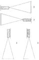
まず、図1および図2により、本発明の実施の形態における投写型表示装置における光学システムの概要について簡単に説明する。図1は、本発明の実施の形態における投写型表示装置(以下、本装置1と略記する)の光学システム2の概略の構成を示す斜視図、図2は、本装置1における4灯合成光学システムの基本構成をそれぞれ示す。
(Embodiment)
First, an outline of an optical system in a projection display apparatus according to an embodiment of the present invention will be briefly described with reference to FIGS. FIG. 1 is a perspective view showing a schematic configuration of an
本装置1における光学システム2は、4個の光源ランプ21a、21b、21c、21dからの出力光を合成する光合成手段としての光合成部3、DMD(Digital Micromirror Device)などの画像表示素子を備えた表示デバイス部5、光合成部3からの出力光を表示デバイス部5に伝搬する集光手段としての集光部4、および表示デバイス部5からの出力光により映像を投写する投写手段としての投写部6を備えている。
The
光学システム2は4個の光源を備え、それぞれの光源は断面形状が楕円面である凹面鏡の内部に配設されている。光源には超高圧水銀灯を使用し、凹面鏡には、ガラス製機材の内面に赤外光を透過させ可視光を反射させる誘電体光学多層膜が形成されている。
The
以下、光学システム2の主要な構成および機能について述べる。
Hereinafter, main configurations and functions of the
光源ランプ21a、21b、21c、21dからの出力光は、凹面鏡22a、22b、22c、22dによってそれぞれ集光され、光源像が合成プリズム23a、23bのミラー面に結像されて、集光レンズ24a、24bに反射される。
The output lights from the
合成プリズム23a、23bを出射した光は、一旦、発散した後、集光レンズ24a、24b、25a、25bを経由することにより、再び収束光となって、合成プリズム26のミラー面で再び発散光として反射され、集光部4に至る。
The light emitted from the combining
合成プリズム23a、23b、26は断面が二等辺三角形の三角柱状であり、光が入射する面には、低屈折率材料と高屈折率材料とを交互に積層した誘電体多層膜ミラーが形成されている。また、光源ランプ21a、21b、21c、21dからの出力光が微小な面積に集光されるため、ミラー面を形成する多層膜に用いる材料には、耐熱性、対紫外線に優れた材料を使用する。
集光部4は、集光レンズ(図示せず)およびミラー(図示せず)などを備え、光合成部3からの出力光の進行径路を整えて表示デバイス部5に伝搬する。
The condensing unit 4 includes a condensing lens (not shown), a mirror (not shown), and the like, and adjusts the traveling path of the output light from the
表示デバイス部5は、全反射プリズム(図示せず)および画像表示素子としての反射型ライトバルブ(図示せず)を備え、投写画像を形成する。反射型ライトバルブは、画素ごとにミラー素子がマトリックス状に配列され、映像信号に応じて光の進行方向を変調し、反射角の変化として光学画像を形成することができる。 The display device unit 5 includes a total reflection prism (not shown) and a reflective light valve (not shown) as an image display element, and forms a projected image. In the reflection type light valve, mirror elements are arranged in a matrix for each pixel, and the traveling direction of light is modulated according to a video signal, and an optical image can be formed as a change in reflection angle.
表示デバイス部5で形成された光学画像は投写部6に出力され、投写部6の投射レンズにより、スクリーン(図示せず)に投写される。
The optical image formed by the display device unit 5 is output to the
なお、本実施の形態においては、ライトバルブとして、光の進行方向を変調する反射型のライトバルブを使用しているが、光の偏光方向や散乱状態を変調するタイプのライトバルブや、透過型ライトバルブのタイプを用いた場合でも同様の効果を発揮することができる。 In this embodiment, a reflection type light valve that modulates the traveling direction of light is used as the light valve. However, a light valve that modulates the polarization direction and scattering state of light, and a transmission type light valve are used. Even when the light valve type is used, the same effect can be exhibited.
つぎに、本装置1の概略の構成について、図3〜図6により説明する。
Next, a schematic configuration of the
図3は、本装置1に搭載された光学システム2を構成する主要な機構部品に関する配置図であり、(a)は正面図、(b)は平面図、(c)は側面図である。また、図4は、本装置1の設置姿勢に関する説明図、図5は、図3の一部拡大断面図、図6は、本装置1の光合成部3に関する要部斜視図をそれぞれ示す。
3A and 3B are layout diagrams regarding main mechanical components constituting the
本装置1は、筺体10の内部に光学システム2を構成する主要な機構部品である光合成部3および投写部6が、図3に示すように配置されている。また、本装置1は、通常、図4(a)に示すように、水平の姿勢で使用するが、図4(b)、図4(c)および図4(d)に示すように、天井に取り付けた姿勢、垂直の姿勢で真上または真下に向けて設置し、表示画像の投写を行うことができる。
In the
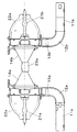
図5は、本装置1に搭載される光合成部3において、対向する二つの光源ランプ21aおよび21bの相互関係、および光源ランプ21a、21bに配設された冷却手段の構成例を示す。
FIG. 5 shows a mutual relationship between two
凹面鏡22a、22bの内部にそれぞれ配設された光源ランプ21a、21bは光軸を共有し、光軸41a、41b(図2)が一致するように構成されている。また、光源ランプ21aには、内部に風量制御弁13aを備えた導風ダクト12aを介して、渦巻き型の送風機(以下、冷却ファンと略記する)11aが接続されている。同様に光源ランプ21bには風量制御弁13bを備えた導風ダクト12bを介して、冷却ファン11bが接続されている。もう一対の対向する光源ランプ21c、21dの相互の関係および冷却手段の構成も、図5に示す光源ランプ21a、21bと同様に構成されている。図6に、二組の対向する光源ランプ21a、21b、21c、21dを使用した場合の光合成部3の構成事例を示す。
The
これにより、光源ランプ21a、21bからの出力光は凹面鏡22a、22bによって反射した後、光軸が揃った状態で導光管内を進行し、第1の合成プリズム23aで再度反射して集光レンズ24a、25aを経由して第2の合成プリズム26に至り、もう一対の対向する光源ランプ21c、21dから到達する出力光と合成することができる。
As a result, the output light from the
また、光源ランプ21a、21b、21c、21dは、点灯時の発熱に対して、冷却ファン11a、11b、11c、11dによりそれぞれ送風を行い、冷却することができる。さらに、風量制御弁13a、13b、13c、13dを動作させることにより、冷却ファンから供給される風量を調節することができる。
Further, the
つぎに、本発明の特徴である、本装置1における光源ランプ21a、21b、21c、21dの温度管理の方法について、図7〜図9により説明する。
Next, a temperature management method for the
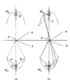
光源ランプが点灯した場合の出力光の光学特性を図7に示す。図7(a)に示すように、光源Aからの出力光は凹面鏡MAおよびプリズムPにおいて反射して、発散光a、bとなり、光径路上を有効光として進行する。一方、図7(b)に示すように、発散光a、bのほかに、プリズムPから外れる光束c、dがあり、この光束は対向する光源Bの凹面鏡MBにより反射して光源Bに至る。したがって、光源A、Bが同時に点灯すると、相互に出力光の一部の照射を受けることとなり、光源を一つだけ点灯する場合に較べて、光源の温度上昇が大きくなる。以上の通り、複数の光源を使用し、それぞれの光源からの出力光を合成して表示デバイスに照射し、映像を投写する場合には、合成されて有効光として使用される出力光の有効成分のほかに、散逸または不要な照射を行う無効成分があることに注意が必要である。例えば、複数の光源からの出力光を合成する装置において、対向する光源を照射し、照射された光源の温度を過度に上昇させる。これが光源の白化、寿命の低下等の問題を発生させる原因となる。 FIG. 7 shows optical characteristics of output light when the light source lamp is turned on. As shown in FIG. 7 (a), the output light from the light source A is reflected at the concave mirror M A and the prism P, and proceeds divergent light a, b, and the upper light path as an effective light. On the other hand, as shown in FIG. 7B, in addition to the diverging lights a and b, there are light beams c and d that deviate from the prism P. The light beams are reflected by the concave mirror MB of the light source B facing to reach the light source B. . Accordingly, when the light sources A and B are turned on simultaneously, a part of the output light is irradiated to each other, and the temperature rise of the light source is larger than when only one light source is turned on. As described above, when using multiple light sources, combining the output light from each light source and irradiating the display device to project an image, the effective components of the output light that are combined and used as effective light Note that in addition to these, there are ineffective components that dissipate or cause unwanted irradiation. For example, in an apparatus that synthesizes output light from a plurality of light sources, the opposing light sources are irradiated, and the temperature of the irradiated light sources is excessively increased. This causes problems such as whitening of the light source and a decrease in life.
これに対して、本装置1では、光源ランプ21a、21b、21c、21dの温度管理の方法として、以下の措置を講じている。
On the other hand, in the
既に述べたように、光源ランプ21a、21b、21c、21dには、それぞれ冷却ファン11a、11b、11c、11dが配設されており、冷却ファンの回転数を制御することができる。これにより、4個の光源における過度の温度上昇を防止することができる。
As described above, the
以下、光源ランプに点灯状況の判定プロセスについて、図8により説明する。 Hereinafter, the determination process of the lighting state of the light source lamp will be described with reference to FIG.
冷却ファンの回転数制御のプロセスがスタートすると、本装置1の設置場所の高度について、二つの区分により判定を行う。本装置1は気圧センサー(図示せず)を備えており、気圧と冷却ファンの冷却効率との関係に関する情報に基づき、「高地」であるか否かによって、冷却ファンの回転数制御の指示を区分する(ステップ1:図8ではS1と略記する。以下、同様とする)。
When the process of controlling the number of rotations of the cooling fan starts, the altitude of the installation location of the
その後、本装置1の設置の姿勢に関する判定を行う。冷却ファンは設置方向により効率に差異が発生するため、本装置1では、設置の姿勢が水平および垂直のいずれであるかにより、冷却ファンの回転数制御の指示を区分する(ステップ2a、2b)。
Then, the determination regarding the installation posture of this
つぎに、光源ランプ21a、21b(あるいは光源ランプ21c、21d)など、対向する光源ランプが同時に点灯するか否かの判定を行う。対向する光源ランプが同時に点灯しない場合は相互の照射による温度上昇が発生しないが、光源ランプが同時に点灯すると相互照射の影響受けるため、光源の温度上昇が大きくなる。したがって、対向する光源ランプが同時に点灯するか否かにより、冷却ファンの回転数制御の指示を区分する(ステップ3a、3b、3c、3d)。
Next, it is determined whether or not the facing light source lamps such as the
以上のプロセスに従って光源ランプの点灯状況の判定を行う。図8に示すように、冷却ファンの回転数制御に関する実施条件を1,800rpm〜3,200rpmの範囲で8段階に区分して、維持制御すべき冷却ファンの回転数を決定する。 The lighting condition of the light source lamp is determined according to the above process. As shown in FIG. 8, the implementation conditions relating to the cooling fan rotation speed control are divided into eight stages in the range of 1,800 rpm to 3,200 rpm, and the rotation speed of the cooling fan to be maintained and controlled is determined.
また、温度センサーを備え、本装置1の設置された周辺の温度を判別し、冷却ファンの回転数制御の指示を区分してもよい。
In addition, a temperature sensor may be provided, the temperature around the installation of the
さらに、設置場所の高度、および設置姿勢は、センサーを設けることなく、設置時に本装置1の高度、設置姿勢情報を設定してもよい。
Further, the altitude and the installation posture of the
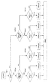
つぎに、光源ランプの点灯状況の判定を行い、判定に従って冷却ファンを駆動するための構成および機能について、図9により説明する。 Next, the configuration and function for determining the lighting condition of the light source lamp and driving the cooling fan according to the determination will be described with reference to FIG.
図9は、本装置1における光源ランプおよび冷却ファンの制御に係わる構成を示すブロック図である。
FIG. 9 is a block diagram illustrating a configuration relating to control of the light source lamp and the cooling fan in the
本装置1は、光源ランプおよび冷却ファンの制御を行うために、電源部901、制御部902および記憶部903を備えている。
The
電源部901には光源ランプ911、912、913、914、および冷却ファン921、922、923、924がそれぞれ独立して接続されており、光源ランプおよび冷却ファンのすべてを、制御部902から受信した指示情報に基づいて、それぞれ個別に駆動し制御することができる。
制御部902は電源部901と接続され、電源部901に対して光源ランプおよび冷却ファンに関する電源のON/OFF、駆動電圧、駆動電流、送風制御(流量制御)などの指示情報を送信し、光源ランプおよび冷却ファンのすべてに関する駆動制御の指示を行う。
The
なお、制御部902には、回転数センサー931、932、933、934、姿勢センサー904、気圧センサー905および温度センサー906がそれぞれ接続されている。
Note that the
回転数センサー931、932、933、934は、冷却ファン921,922,923にそれぞれ配設されており、冷却ファンの回転数を検出し、制御部902に検出情報を送信することができる。
The
姿勢センサー904は、本装置1の設置姿勢を検出する機能を備え、制御部902に検出情報を送信することができる。姿勢センサー904は、本装置1の筺体10(図3)の内部に配設され(図示せず)る。センサーの材料としては、感圧素子などを使用することができる。
The
気圧センサー905は、本装置1が設置された場所の気圧を検出し、制御部902に検出情報を送信することができる。気圧センサー905は、姿勢センサー904と同様に、感圧素子などを使用して、本装置1の筺体10の内部または外部に配設する。
The
温度センサー906は、本装置1が設置された場所の気温を検出し、制御部902に検出情報を送信することができる。温度センサー906は、本装置1の筺体10の吸気口近傍に配設する。
The
記憶部903には、上記の各種センサーから受信した情報に基づいて光源ランプおよび冷却ファンの制御条件を決定するための制御プログラムやデータベースなどが予め保存されている。
The
以上の通り、本発明による投写型表示装置によれば、複数の光源を使用した投写型表示装置において、光源の温度管理の不備に起因する光源の白化、寿命の低下、黒化、輝度低下などの課題を解決することができる。 As described above, according to the projection display device according to the present invention, in the projection display device using a plurality of light sources, whitening of the light source due to inadequate temperature management of the light source, reduction in life, blackening, luminance reduction, etc. The problem can be solved.
本発明の構成によれば、複数の光源を使用した投写型表示装置において、光源の温度管理に関し高精度で確実な制御が可能となり、光源の白化、寿命の低下、黒化、輝度低下などを抑制し、小型、超高輝度で信頼性の高い投写型表示装置を実現することができる。 According to the configuration of the present invention, in a projection display apparatus using a plurality of light sources, high-accuracy and reliable control can be performed with respect to the temperature management of the light sources, and light source whitening, life reduction, blackening, luminance reduction, etc. Therefore, it is possible to realize a projection display device that is small, ultra-high brightness, and highly reliable.
なお、本実施の形態においては、4個の光源を使用しているが、2個または4個以上の光源数であっても、同様の考え方に基づいて投写型表示装置を構成することができることは、言うまでもない。 In this embodiment, four light sources are used. However, even if the number of light sources is two or four or more, the projection display device can be configured based on the same concept. Needless to say.
本発明の構成によれば、複数の光源を使用した投射型表示装置において、光源の温度管理に関し、高精度で確実な制御が可能であり、光源の劣化や寿命の低下などが発生しにくく、超高輝度で高い信頼性が求められるプロジェクター等の投写型表示装置として有用である。 According to the configuration of the present invention, in the projection display device using a plurality of light sources, high-accuracy and reliable control is possible with respect to the temperature management of the light sources, and the deterioration of the light sources and the decrease in the lifetime are unlikely to occur. It is useful as a projection display device such as a projector that requires ultra-high brightness and high reliability.
1 投写型表示装置
2 4灯合成光学システム(光学システム)
3 光合成部
4 集光部
5 表示デバイス部
6 投写部
7a,7b,76c, 脚部
10 筺体
11a,11b,11c,11d,921,922,923,924 冷却ファン
12a,12b 導風ダクト
13a,13b 風量制御弁
14a,14b,14c,14d 導光管
21a,21b,21c,21d,911,912,913,914 光源ランプ
22a,22b,22c,22d 凹面鏡
23a,23b,26 合成プリズム
24a,24b,25a,25b,27 集光レンズ
28 投写レンズ
41a,41b,41c,41d,42 光軸
901 電源部
902 制御部
903 記憶部
904 姿勢センサー
905 気圧センサー
906 温度センサー
931,932,933,934 回転数センサー
DESCRIPTION OF
DESCRIPTION OF
Claims (5)
Priority Applications (3)
| Application Number | Priority Date | Filing Date | Title |
|---|---|---|---|
| JP2008197320A JP2010032944A (en) | 2008-07-31 | 2008-07-31 | Projection display device |
| US12/504,904 US8022348B2 (en) | 2008-07-31 | 2009-07-17 | Projection type display apparatus having a controlling unit for controlling a rotation rate of the fan of a cooling unit with reference to information regarding lighting state of light sources |
| CN2009101611143A CN101639614B (en) | 2008-07-31 | 2009-07-31 | Projection type display apparatus |
Applications Claiming Priority (1)
| Application Number | Priority Date | Filing Date | Title |
|---|---|---|---|
| JP2008197320A JP2010032944A (en) | 2008-07-31 | 2008-07-31 | Projection display device |
Publications (2)
| Publication Number | Publication Date |
|---|---|
| JP2010032944A true JP2010032944A (en) | 2010-02-12 |
| JP2010032944A5 JP2010032944A5 (en) | 2011-07-28 |
Family
ID=41607996
Family Applications (1)
| Application Number | Title | Priority Date | Filing Date |
|---|---|---|---|
| JP2008197320A Pending JP2010032944A (en) | 2008-07-31 | 2008-07-31 | Projection display device |
Country Status (3)
| Country | Link |
|---|---|
| US (1) | US8022348B2 (en) |
| JP (1) | JP2010032944A (en) |
| CN (1) | CN101639614B (en) |
Cited By (10)
| Publication number | Priority date | Publication date | Assignee | Title |
|---|---|---|---|---|
| WO2012017541A1 (en) * | 2010-08-05 | 2012-02-09 | Necディスプレイソリューションズ株式会社 | Image display apparatus and method of cooling light source |
| WO2012025986A1 (en) * | 2010-08-24 | 2012-03-01 | Necディスプレイソリューションズ株式会社 | Image display device and light source cooling method |
| JP2012155181A (en) * | 2011-01-27 | 2012-08-16 | Mitsubishi Electric Corp | Projection device and light source control method therefor |
| WO2012124053A1 (en) * | 2011-03-15 | 2012-09-20 | Necディスプレイソリューションズ株式会社 | Light source device and projection display device |
| JP2014002360A (en) * | 2012-05-22 | 2014-01-09 | Panasonic Corp | Projection-type display apparatus |
| US8960922B2 (en) | 2011-07-05 | 2015-02-24 | Seiko Epson Corporation | Projector and control method of the same |
| JP2015187682A (en) * | 2014-03-27 | 2015-10-29 | セイコーエプソン株式会社 | projector |
| JP2017072100A (en) * | 2015-10-08 | 2017-04-13 | コベルコ建機株式会社 | Fan control device for construction machine |
| US9706181B2 (en) | 2015-04-10 | 2017-07-11 | Panasonic Intellectual Propery Management Co., Ltd. | Projector with a plurality of light sources having dimming capabilities |
| US9891512B2 (en) | 2014-07-17 | 2018-02-13 | Canon Kabushiki Kaisha | Image projection apparatus and storage medium storing light source power control program |
Families Citing this family (9)
| Publication number | Priority date | Publication date | Assignee | Title |
|---|---|---|---|---|
| JP5536216B2 (en) * | 2010-08-16 | 2014-07-02 | Necディスプレイソリューションズ株式会社 | Image display device and light source cooling method |
| JP5606895B2 (en) * | 2010-12-16 | 2014-10-15 | 三洋電機株式会社 | Projection display |
| JP5611800B2 (en) * | 2010-12-16 | 2014-10-22 | 三洋電機株式会社 | Projection display |
| US9386665B2 (en) | 2013-03-14 | 2016-07-05 | Honeywell International Inc. | System for integrated lighting control, configuration, and metric tracking from multiple locations |
| JP2015215377A (en) * | 2014-05-07 | 2015-12-03 | ソニー株式会社 | Image display device and control method of air blowing fan |
| CN105319818B (en) | 2014-07-15 | 2017-11-21 | 中强光电股份有限公司 | Light source module |
| CN106224917A (en) * | 2016-07-21 | 2016-12-14 | 广州市升龙灯光设备有限公司 | The bulb temperature control method of a kind of stage lighting and device |
| CN110609432B (en) * | 2018-06-15 | 2021-06-15 | 深圳光峰科技股份有限公司 | Projection device and color wheel protection method thereof |
| CN112696376A (en) * | 2020-12-28 | 2021-04-23 | 四川长虹电器股份有限公司 | Method for controlling rotating speed of fan of projection equipment |
Citations (3)
| Publication number | Priority date | Publication date | Assignee | Title |
|---|---|---|---|---|
| JPH0990511A (en) * | 1995-09-26 | 1997-04-04 | Fujitsu Ltd | Projection type display device |
| JP2006091610A (en) * | 2004-09-27 | 2006-04-06 | Sanyo Electric Co Ltd | Projection type video display device |
| JP2007078734A (en) * | 2005-09-09 | 2007-03-29 | Sanyo Electric Co Ltd | Projector device |
Family Cites Families (7)
| Publication number | Priority date | Publication date | Assignee | Title |
|---|---|---|---|---|
| JP3581568B2 (en) | 1998-06-15 | 2004-10-27 | 松下電器産業株式会社 | Illumination device and projection display device using the same |
| US6464375B2 (en) * | 1998-03-12 | 2002-10-15 | Matsushita Electric Industrial Co., Ltd. | Lens element and illumination optical apparatus and projection display apparatus |
| JP2000171901A (en) | 1998-09-28 | 2000-06-23 | Matsushita Electric Ind Co Ltd | Lighting optical device and projection type display device |
| JP3645890B2 (en) * | 2002-06-07 | 2005-05-11 | Necビューテクノロジー株式会社 | Projector device |
| JP4378110B2 (en) * | 2003-06-02 | 2009-12-02 | キヤノン株式会社 | Projection display |
| KR101074984B1 (en) * | 2004-03-11 | 2011-10-18 | 톰슨 라이센싱 | Multiple lamp illumination system with polarization recovery and integration |
| JP4845364B2 (en) | 2004-10-06 | 2011-12-28 | キヤノン株式会社 | Projection display device and control method |
-
2008
- 2008-07-31 JP JP2008197320A patent/JP2010032944A/en active Pending
-
2009
- 2009-07-17 US US12/504,904 patent/US8022348B2/en active Active
- 2009-07-31 CN CN2009101611143A patent/CN101639614B/en active Active
Patent Citations (3)
| Publication number | Priority date | Publication date | Assignee | Title |
|---|---|---|---|---|
| JPH0990511A (en) * | 1995-09-26 | 1997-04-04 | Fujitsu Ltd | Projection type display device |
| JP2006091610A (en) * | 2004-09-27 | 2006-04-06 | Sanyo Electric Co Ltd | Projection type video display device |
| JP2007078734A (en) * | 2005-09-09 | 2007-03-29 | Sanyo Electric Co Ltd | Projector device |
Cited By (16)
| Publication number | Priority date | Publication date | Assignee | Title |
|---|---|---|---|---|
| JP5561804B2 (en) * | 2010-08-05 | 2014-07-30 | Necディスプレイソリューションズ株式会社 | Image display device and light source cooling method |
| US9250503B2 (en) | 2010-08-05 | 2016-02-02 | Nec Display Solutions, Ltd. | Image display device and light source cooling method |
| WO2012017541A1 (en) * | 2010-08-05 | 2012-02-09 | Necディスプレイソリューションズ株式会社 | Image display apparatus and method of cooling light source |
| CN103080835B (en) * | 2010-08-24 | 2015-05-27 | Nec显示器解决方案株式会社 | Image display device and light source cooling method |
| CN103080835A (en) * | 2010-08-24 | 2013-05-01 | Nec显示器解决方案株式会社 | Image display device and light source cooling method |
| US9104059B2 (en) | 2010-08-24 | 2015-08-11 | Nec Display Solutions, Ltd. | Image display device and light source cooling method |
| WO2012025986A1 (en) * | 2010-08-24 | 2012-03-01 | Necディスプレイソリューションズ株式会社 | Image display device and light source cooling method |
| JP2012155181A (en) * | 2011-01-27 | 2012-08-16 | Mitsubishi Electric Corp | Projection device and light source control method therefor |
| WO2012124053A1 (en) * | 2011-03-15 | 2012-09-20 | Necディスプレイソリューションズ株式会社 | Light source device and projection display device |
| US9285663B2 (en) | 2011-03-15 | 2016-03-15 | Nec Display Solutions, Ltd. | Projection display device having light source with plurality of port groups each having opening and closing plate |
| US8960922B2 (en) | 2011-07-05 | 2015-02-24 | Seiko Epson Corporation | Projector and control method of the same |
| JP2014002360A (en) * | 2012-05-22 | 2014-01-09 | Panasonic Corp | Projection-type display apparatus |
| JP2015187682A (en) * | 2014-03-27 | 2015-10-29 | セイコーエプソン株式会社 | projector |
| US9891512B2 (en) | 2014-07-17 | 2018-02-13 | Canon Kabushiki Kaisha | Image projection apparatus and storage medium storing light source power control program |
| US9706181B2 (en) | 2015-04-10 | 2017-07-11 | Panasonic Intellectual Propery Management Co., Ltd. | Projector with a plurality of light sources having dimming capabilities |
| JP2017072100A (en) * | 2015-10-08 | 2017-04-13 | コベルコ建機株式会社 | Fan control device for construction machine |
Also Published As
| Publication number | Publication date |
|---|---|
| US20100026965A1 (en) | 2010-02-04 |
| CN101639614B (en) | 2012-06-06 |
| US8022348B2 (en) | 2011-09-20 |
| CN101639614A (en) | 2010-02-03 |
Similar Documents
| Publication | Publication Date | Title |
|---|---|---|
| JP2010032944A (en) | Projection display device | |
| US7922335B2 (en) | Projector | |
| US7535711B2 (en) | Wind velocity measuring device and electronic apparatus | |
| JP4582139B2 (en) | projector | |
| US8142028B2 (en) | Projection type display device | |
| JP5488293B2 (en) | Light source device and projector | |
| JP2011180241A (en) | Projector device | |
| TWI354810B (en) | Optical system unit and projector | |
| JP2004354853A (en) | Cooling device, optical device and projector equipped with cooling device | |
| JP2006337678A (en) | Projection type display apparatus | |
| JP2009163075A (en) | Projection type video display apparatus | |
| CN102147558A (en) | Projection type display apparatus | |
| US9298073B2 (en) | Projector and method for controlling projector | |
| US20150029470A1 (en) | Image projection apparatus and method for controlling image projection apparatus | |
| JP4175327B2 (en) | Projector device | |
| JP2006047980A (en) | Method of reducing temperature difference between upper and lower portions of lamp bulb, optical unit, projection type display apparatus, and projection television apparatus | |
| JP2009198640A (en) | Projector | |
| JP2000047328A (en) | Image projection device | |
| JP2011209382A (en) | Light source device and projector | |
| JP2008052931A (en) | Light source device and projector | |
| JP2011203515A (en) | Light source device and projector | |
| JP2007206604A (en) | Projector | |
| JP5874763B2 (en) | Light source device and projector | |
| JP4811482B2 (en) | Light source device and projector | |
| JP2011118152A (en) | Projection type display apparatus |
Legal Events
| Date | Code | Title | Description |
|---|---|---|---|
| A521 | Written amendment |
Free format text: JAPANESE INTERMEDIATE CODE: A523 Effective date: 20110609 |
|
| A621 | Written request for application examination |
Free format text: JAPANESE INTERMEDIATE CODE: A621 Effective date: 20110609 |
|
| RD01 | Notification of change of attorney |
Free format text: JAPANESE INTERMEDIATE CODE: A7421 Effective date: 20110713 |
|
| A977 | Report on retrieval |
Free format text: JAPANESE INTERMEDIATE CODE: A971007 Effective date: 20120829 |
|
| A131 | Notification of reasons for refusal |
Free format text: JAPANESE INTERMEDIATE CODE: A131 Effective date: 20120904 |
|
| A521 | Written amendment |
Free format text: JAPANESE INTERMEDIATE CODE: A523 Effective date: 20121029 |
|
| RD01 | Notification of change of attorney |
Free format text: JAPANESE INTERMEDIATE CODE: A7421 Effective date: 20121213 |
|
| A02 | Decision of refusal |
Free format text: JAPANESE INTERMEDIATE CODE: A02 Effective date: 20130312 |