JP2010031940A - Pipe bracing device - Google Patents
Pipe bracing device Download PDFInfo
- Publication number
- JP2010031940A JP2010031940A JP2008193693A JP2008193693A JP2010031940A JP 2010031940 A JP2010031940 A JP 2010031940A JP 2008193693 A JP2008193693 A JP 2008193693A JP 2008193693 A JP2008193693 A JP 2008193693A JP 2010031940 A JP2010031940 A JP 2010031940A
- Authority
- JP
- Japan
- Prior art keywords
- pipe
- main pipe
- joined
- vibration device
- joining
- Prior art date
- Legal status (The legal status is an assumption and is not a legal conclusion. Google has not performed a legal analysis and makes no representation as to the accuracy of the status listed.)
- Granted
Links
Images


Abstract
Description
本発明は、建物に設置される配管の振止めに用いられる配管振止め装置に関する。 The present invention relates to a piping anti-vibration device used for anti-vibration of piping installed in a building.
従来、鉛直方向に延びる竪管の水平方向荷重を支持する装置として、竪管の周囲に配置される架台と、架台に設置されて竪管を囲む円形または多角形の枠部材と、この枠部材に接続された調整用のアームと、枠部材に取付けられて竪管との間に挿入される緩衝材と、を備える振動緩衝支持装置がある(特許文献1を参照)。 Conventionally, as a device for supporting the horizontal load of a vertical pipe extending in the vertical direction, a pedestal arranged around the vertical pipe, a circular or polygonal frame member installed on the pedestal and surrounding the vertical pipe, and the frame member There is a vibration buffering support device that includes an adjustment arm connected to the frame member, and a buffer member that is attached to the frame member and inserted between the armature tube (see Patent Document 1).
また、環状に形成された支持枠と、頭部に弾性体を取付けたボルトを備え、このボルトを支持枠に対しその中心方向に頭部が位置するように取付けた管取付金具がある(特許文献2を参照)。
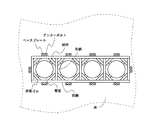
従来、配管内の流体の流動音や振動が建築構造体へ伝播することを防ぐ目的や、地震等に起因する建築構造体の大きな振動に際しても配管を安全に保持する目的で、竪管の水平方向における振れを制限するための装置が用いられている。このような目的で設置される配管振止め装置としては、例えば、竪管を取り囲むように井桁に組まれた鉄骨の形鋼と、井桁の内部に取付けられた斜材と、斜材に設けられて竪管の横振れを止める防振ゴムとを備えるものがある。図7は、このような従来の配管振止め装置の構成の概略を示す平面図である。このような配管振止め装置を用いた場合、竪管が振れた場合の力の伝達経路は、竪管、防振ゴム、斜材、形鋼、ベースプレート、アンカーボルト、床、の順となる。 Conventionally, horizontal pipes have been installed horizontally for the purpose of preventing the flow noise and vibration of the fluid in the pipe from propagating to the building structure, and for keeping the pipe safely in the event of large vibrations of the building structure caused by earthquakes, etc. A device is used to limit the deflection in the direction. For example, a pipe anti-vibration device installed for such a purpose is provided on a steel frame shaped steel frame that is assembled in a cross girder so as to surround a steel pipe, a diagonal member mounted inside the cross girder, and a diagonal member. Some of them have anti-vibration rubber that stops the horizontal vibration of the pipe. FIG. 7 is a plan view showing an outline of the configuration of such a conventional pipe anti-vibration device. When such a pipe bracing device is used, the force transmission path when the soot tube shakes is in the following order: soot tube, anti-vibration rubber, diagonal material, shape steel, base plate, anchor bolt, floor.
しかし、このような配管振止め装置は、形鋼および斜材によって竪管を囲う必要があったためにユニット化されておらず、また、現場組み立てにおいて溶接作業を行う必要がある。このため、竪管に対してこのような配管振止め装置を設置するにあたっては、建物の各階に溶接機器が必要であった。また、その他にも、エレベータ等を用いて長物の鋼材を搬入することの困難さや、組み立てに多大な時間を要するといった問題があった。 However, such a pipe bracing device is not unitized because it is necessary to enclose the steel pipe with the shape steel and the diagonal material, and it is necessary to perform a welding operation in the on-site assembly. For this reason, in order to install such a pipe anti-vibration device for a steel pipe, welding equipment is required on each floor of the building. In addition, there are problems that it is difficult to carry a long steel material using an elevator or the like, and that much time is required for assembly.
また、上記特許文献1および特許文献2に開示されるような、配管を取り囲む枠部材や支持枠を設置し、この枠に対して直接または間接に取付けられた緩衝材を用いて配管の振止めを行う装置がある。しかし、このような装置においても、竪管が振れた場合の力の伝達経路にある枠部材や支持枠の強度を確保するために装置自体が大きくなるという問題や、構造が複雑であり部品点数が多いという問題があった。
In addition, as disclosed in
本発明は、上記した問題に鑑み、構造がシンプルであり且つ十分な強度が得られる配管振止め装置を提供することを課題とする。 In view of the above-described problems, an object of the present invention is to provide a piping anti-vibration device having a simple structure and sufficient strength.
本発明は、上記した課題を解決するために、緩衝材を支持するアーム部と床に固定されるベース部とを摩擦接合によって接合させ、摩擦によって主管の振れを床に伝達させることで、構造がシンプルであり且つ十分な強度が得られる配管振止め装置を提供することを可能にした。 In order to solve the above-described problems, the present invention has a structure in which an arm portion supporting a cushioning material and a base portion fixed to a floor are joined by friction joining, and the vibration of the main pipe is transmitted to the floor by friction. This makes it possible to provide a piping anti-vibration device that is simple and can provide sufficient strength.
詳細には、本発明は、建物に設置される主管の振止めに用いられる配管振止め装置であって、該配管振止め装置が設置された状態で、前記主管の外周の一部に面するように配置される緩衝材と、前記緩衝材を支持し、摩擦接合のための接合面を有するアーム部と、前記主管の近傍の床に固定され、前記アーム部を接合するために前記接合面と摩擦接合される被接合面を有するベース部と、を備え、摩擦接合された前記接合面および被接合面は、前記主管の軸を通る面と略一致する、配管振止め装置である。 Specifically, the present invention is a pipe anti-vibration device used for anti-vibration of a main pipe installed in a building, and faces the part of the outer periphery of the main pipe with the pipe anti-vibration apparatus installed. A cushioning material arranged in such a manner, an arm portion supporting the cushioning material and having a joining surface for friction joining, and the joining surface fixed to the floor near the main pipe and joining the arm portion And a base portion having a surface to be joined that is friction-joined, and the joining surface and the surface to be joined that are friction-joined are substantially the same as a surface passing through the axis of the main pipe.
本発明において、主管とは、建物における配管のうち、各フロアや各部屋に配置される枝管に分岐する前の共用部分の配管であり、必ずしも縦方向に延びた配管のみを指すものではない。本発明に係る配管振止め装置は、このような主管に対して設けられ、配管内の流体の流動音や振動が建築構造体へ伝播することを防ぐ目的や、地震等に起因する大きな振れに際しても配管を安全に保持する目的で、主に主管の水平方向の振れを制限するための装置である。 In the present invention, the main pipe is a pipe of a common part before branching to a branch pipe arranged in each floor or room among pipes in a building, and does not necessarily indicate only a pipe extending in the vertical direction. . The pipe anti-vibration device according to the present invention is provided for such a main pipe, and is intended to prevent the flow noise and vibration of the fluid in the pipe from propagating to the building structure, or in the case of a large shake caused by an earthquake or the like. This is a device mainly for restricting the horizontal deflection of the main pipe for the purpose of holding the pipe safely.
緩衝材は、主管に接触することで主管の振れを直接緩衝するための部材であり、例えば、ゴムやスプリング等を用いることが出来る。緩衝材は、本発明に係る配管振止め装置が設置された状態で、主管の外周の一部に面するように配置される。ここで、緩衝材と主管外周との間の間隔は、主管の振れが所定の振れ幅以上となったときに緩衝材と主管外周とが接触する間隔としてもよいし、主管が振れていない状態で接触していてもよい。 The buffer material is a member for directly buffering the vibration of the main pipe by coming into contact with the main pipe. For example, rubber or a spring can be used. The cushioning material is disposed so as to face a part of the outer periphery of the main pipe in a state in which the pipe anti-vibration device according to the present invention is installed. Here, the interval between the buffer material and the outer periphery of the main pipe may be an interval at which the buffer material and the outer periphery of the main pipe come into contact with each other when the deflection of the main pipe becomes equal to or larger than a predetermined swing width, or the main pipe is not shaken. May be in contact.
そして、本発明に係る配管振止め装置は、このような緩衝材を支持するアーム部と、主管近傍の床に固定されたベース部とが、接合面と被接合面との摩擦接合によって接合される。この摩擦接合に係る接合面および被接合面は、主管の軸を通る面に略一致する。即ち、本発明では、従来主管の周囲に設置した枠によって緩衝材に伝達した力を受けていたところ、このような摩擦接合面で力を伝達することとしている。このため、本発明によれば、配管振止め装置としての信頼性を損なわずに装置全体の構成を従来に比べて格段に単純化し、部品点数を抑えた配管振止め装置を提供することが可能である。 In the pipe anti-vibration device according to the present invention, the arm portion that supports such a cushioning material and the base portion fixed to the floor near the main pipe are joined by friction joining between the joining surface and the surface to be joined. The The joining surface and the to-be-joined surface relating to the friction welding substantially coincide with a surface passing through the axis of the main pipe. In other words, according to the present invention, when the force transmitted to the buffer material is received by the frame installed around the main pipe, the force is transmitted by such a friction joint surface. For this reason, according to the present invention, it is possible to provide a piping anti-vibration device that greatly simplifies the configuration of the entire device and reduces the number of parts without impairing the reliability of the piping anti-vibration device. It is.
また、従来の同種装置では、構造が複雑であり部品点数が多いために、組み立てには多大な時間が必要となるといった問題や、配管を取り囲む枠部材や支持枠を用いるために、配管の設置に先立って設置される必要があるといった問題があった。しかし、本発明に係る配管振止め装置は、構成が単純化され、部品点数が抑えられているために、設置が容易であり、また、主管を取り囲む枠を必要としない構成であるために、主管の設置後にも、容易に追加設置することが出来る。 In addition, in the conventional similar devices, the structure is complicated and the number of parts is large, so that it takes a lot of time to assemble, and because the frame member and support frame surrounding the pipe are used, the installation of the pipe There was a problem that it was necessary to be installed prior to. However, the piping anti-vibration device according to the present invention is simplified in configuration and has a reduced number of parts, so that it is easy to install and does not require a frame surrounding the main pipe. Even after the main pipe is installed, it can be easily installed.
また、前記緩衝材と前記主管との距離は、前記接合面と前記被接合面との接合位置によって調整されてもよい。即ち、本発明に係る配管振止め装置は、アーム部とベース部とを摩擦接合によって接合することとしたために、接合位置の設定によって、緩衝材と主管との距離を調整することが出来る。 The distance between the cushioning material and the main pipe may be adjusted according to the joining position between the joining surface and the joined surface. That is, since the pipe anti-vibration device according to the present invention joins the arm portion and the base portion by friction joining, the distance between the buffer material and the main pipe can be adjusted by setting the joining position.
より具体的には、本発明に係る配管振止め装置において、前記接合面と前記被接合面とは、高力ボルトを用いて摩擦接合され、前記ベース部は、前記高力ボルトの締結位置を前記主管の径方向において調整可能なボルト孔を有してもよい。このようにすることで、高力ボルトの締結位置によって緩衝材と主管との距離を調整することが出来る。例えば、アーム部側またはベース部側のボルト孔のうち少なくとも何れかを横長のボルト孔とすることで、このボルト孔の横長の範囲内で任意に高力ボルトの締結位置を設定し、床に固定されたベース部にアーム部が接合される位置、ひいては緩衝材と主管外周との間隔を調整することが出来る。但し、高力ボルトの締結位置を選択可能とするための具体的な構成には、その他の具体的構成が採用されてもよい。例えば、アーム部またはベース部の少なくとも何れかに、選択可能な複数のボルト孔を設けることによっても、高力ボルトの締結位置
を選択可能とすることが出来る。
More specifically, in the pipe bracing device according to the present invention, the joining surface and the joined surface are friction-joined using a high-strength bolt, and the base portion has a fastening position of the high-strength bolt. You may have an adjustable bolt hole in the radial direction of the main pipe. By doing in this way, the distance of a buffer material and a main pipe can be adjusted with the fastening position of a high strength volt | bolt. For example, by setting at least one of the bolt holes on the arm part side or the base part side as a horizontally long bolt hole, the fastening position of the high strength bolt can be arbitrarily set within the horizontally long range of this bolt hole, and The position where the arm part is joined to the fixed base part, and the distance between the buffer material and the outer periphery of the main pipe can be adjusted. However, other specific configurations may be adopted as a specific configuration for enabling selection of the fastening position of the high strength bolt. For example, the fastening position of the high-strength bolt can be selected by providing a plurality of selectable bolt holes in at least one of the arm part and the base part.
また、前記ベース部は、互いに隣接して設置された複数の主管の振止めに用いられる複数の前記アーム部が接合されるための、複数の被接合面を有してもよい。即ち、ベース部は、隣り合う主管の振止めに用いられるアーム部によって共用されてもよい。このようにすることで、床におけるベース部の設置面積を抑え、建物におけるパイプスペースの面積を小さくすることが出来る。即ち、本発明によれば、パイプスペースの面積を抑え、ひいては建物のレンタブル比を向上させることが可能である。 The base portion may have a plurality of surfaces to be joined for joining a plurality of the arm portions used for swinging a plurality of main pipes installed adjacent to each other. In other words, the base portion may be shared by the arm portion used for shaking the adjacent main pipe. By doing in this way, the installation area of the base part in a floor can be suppressed, and the area of the pipe space in a building can be made small. That is, according to the present invention, it is possible to reduce the area of the pipe space and improve the rentable ratio of the building.
また、互いに隣接して設置された2本の主管の振止めに用いられる複数の前記アーム部が接合される前記ベース部は、該2本の主管近傍の床のうち、該2本の主管に挟まれた領域の中心よりも該領域の外側にずれた位置に固定されてもよい。本願に係る配管振止め装置は、従来の配管振止め装置と異なり枠部材が不要であるため、このようにして、ベース部を主管に挟まれた領域の中心以外の位置に固定することが可能である。そして、ベース部が主管に挟まれた領域の中心に固定されないことで、隣り合う主管同士の間隔を狭くすることが出来る。これによって、パイプスペースの面積を抑え、建物のレンタブル比を向上させることが可能である。 In addition, the base part to which the plurality of arm parts used for swinging two main pipes installed adjacent to each other is joined to the two main pipes in the floor near the two main pipes. You may fix to the position shifted | deviated to the outer side of this area | region rather than the center of the area | region pinched | interposed. Since the pipe anti-vibration device according to the present application does not require a frame member, unlike the conventional pipe anti-vibration device, the base portion can be fixed at a position other than the center of the region sandwiched between the main pipes in this way. It is. And since a base part is not fixed to the center of the area | region pinched | interposed into the main pipe, the space | interval of adjacent main pipes can be narrowed. As a result, the area of the pipe space can be reduced, and the rentable ratio of the building can be improved.
また、前記アーム部は、前記接合面が設けられた接合部と、該接合部の一端に接合され、複数の前記緩衝材が設けられる緩衝材設置部と、を有してもよい。一のアーム部に対して複数の緩衝材を設置することで、ベース部およびアーム部の設置に必要な面積および空間を少なく抑えたまま、主管の振れを抑制するために主管の外周に面して設置される緩衝材を多く設置することが出来る。そして、このようにして一のアーム部に対して複数の緩衝材を設置することで、振れの緩衝のために主管に面する緩衝材の面積を大きくすることが出来、流動音や振動を効果的に抑制し、主管をより安全に保持することが出来る。 In addition, the arm portion may include a joint portion provided with the joint surface and a shock absorber installation portion that is joined to one end of the joint portion and provided with a plurality of the shock absorbers. By installing multiple cushioning materials on one arm part, it faces the outer periphery of the main pipe in order to suppress the main pipe runout while keeping the area and space required for installation of the base part and arm part small. Many cushioning materials can be installed. And by installing a plurality of cushioning materials for one arm in this way, it is possible to increase the area of the cushioning material facing the main pipe for buffering vibrations, and it is effective for flowing sound and vibration The main pipe can be held more safely.
本発明によって、構造がシンプルであり且つ十分な強度が得られる配管振止め装置を提供することが可能となる。 According to the present invention, it is possible to provide a pipe rocking device having a simple structure and sufficient strength.
本発明に係る配管振止め装置の実施の形態について、図面に基づいて説明する。 DESCRIPTION OF EMBODIMENTS Embodiments of a pipe suspension device according to the present invention will be described with reference to the drawings.
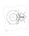
図1は、本実施形態に係る配管振止め装置1を示す平面図であり、図2は、本実施形態に係る配管振止め装置1を示す側面図である。ここで、図1および図2は、主管2に対して設置された状態の配管振止め装置1を示す。配管振止め装置1は、主管2を通すために床9に設けられた開口91の縁周辺に固定され、緩衝材30が主管2の外周に面して設けられることで、主管2の振れを緩衝し、また主管2の振れの力を床9(建築物構造体)へ伝達させる装置である。本実施形態では、300A以上の大口径配管に適した配管振止め装置1を提供する。配管振止め装置1は、緩衝材30、緩衝材30を支持するアーム部10、アーム部10が固定されるベース部20を備える。
FIG. 1 is a plan view showing a pipe
本実施形態において、ベース部20は、アンカーボルト40を用いて床9に固定されるベース基部21と、ベース基部21に立設される立設部22と、を有する。立設部22は板状の金属部材であり、その一方の面は、アーム部10との接合に用いられる被接合面24である(図3を参照)。また、立設部22の被接合面24の中心付近には、ボルト孔23が設けられる。このボルト孔23は、アーム部10に設けられたボルト孔13と位置合わせされ、高力ボルト50を用いて摩擦接合するためのボルト孔23である。また、ボルト孔23は、アーム部10の接合位置を任意に設定可能なように、主管2の径方向に延びた長孔である。このようにすることで、この長孔の横長の範囲内で、設置作業者は、ボル
トの締結位置を任意に選択することが出来る。
In the present embodiment, the
本実施形態において、アーム部10は、上記高力ボルト50を用いてベース部20の被接合面24に接合されるための接合面14を有する接合部11と、主管2側の端に溶接された緩衝材設置部12と、を有する。また、接合面14の中心付近には、ボルト孔13が設けられる。このボルト孔13は、ベース部20に設けられたボルト孔23と位置合わせされ、高力ボルト50を用いて摩擦接合するためのボルト孔13であり、ベース部20のボルト孔同様23、接合位置を任意に設定可能な長孔である。ボルト孔13が長孔であることで、アーム部10をベース部20に接合する際の接合位置、ひいては主管2の外周と緩衝材30との距離を任意に設定することが可能である。
In this embodiment, the
また、主管2の外周と緩衝材30との距離を設定可能であるために、本実施形態に係る配管振止め装置1によれば、建築現場における施工誤差による寸法歪の微調整が可能である。但し、主管2の外周と緩衝材30との距離を設定可能とするための手段にはその他の手段が採用されても良いし、長孔を用いて設定可能とする場合にも、長孔はアーム部10またはベース部20の何れか一方に設けられていればよい。
Moreover, since the distance between the outer periphery of the
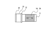
緩衝材設置部12は、片面(該片面の反対面は、接合部11が溶接される面である。詳細は後述する。)が主管2に向けられる板状の部材がその中心付近で内向き(主管2向き)に曲げられることによって(本実施形態では、角度にして約33.2度)形成される。この曲げによって、板状の部材の前記片面は、夫々が主管2の外周の接線と略平行となる2つの平面を形成する。接合部11の一端にこのような緩衝材設置部12が接続されていることで、一のアームにおいて主管2に対して設置できる緩衝材30を2つとすることが出来、主管2が振れた際に主管2の振れを緩衝および抑制する部材の主管2に接する面積を大きくすることが出来る。アーム部10は、緩衝材設置部12が、曲げ部分の背面において接合部11の端に溶接されることによって作成されている。また、緩衝材設置部12には、緩衝材30を、ネジを用いて固定するためのネジ孔が設けられている。本実施形態において、緩衝材30は、緩衝材設置部12に、ネジおよび接着等の固定手段を用いて固定される。
The cushioning
本実施形態において、緩衝材30は、丸型防振ゴム31と、丸型防振ゴム31と異なるばね定数を有するゴム32とが張り合わされた部材である。本実施形態では、丸型防振ゴム31の主管2に面する部分に、丸型防振ゴム31に比べてばね定数の低いゴム32を設けることで、地震等による大きな振れによっても主管2を安全に保ちつつ、主管2における流動音等を低減することを可能としている。より詳細には、本実施形態では、配管内の流体の流動音や振動に多い周波数を有する振動の低減に優れた所定のばね定数を有するゴム32によって、振れが小さい、配管内の流体等に起因する通常の振動を低減させ、その上で、振れが所定以上の大きさになった場合に、大きな荷重への耐性に優れたばね定数を有する丸型防振ゴム31によって、振れが大きい、地震等に起因する大きな荷重に対しても主管2を安全に保つこととしている。
In the present embodiment, the cushioning
また、本実施形態において、配管振止め装置1は、接合面14および被接合面24が、主管2の軸を通る面と略一致するように(換言すると、接合面14および被接合面24の面が延びる方向が主管2の軸心を通るように)設置される。即ち、本実施形態に係る配管振止め装置1は、アーム部とベース部とを摩擦接合する摩擦面が、主管2の軸を通る面と略一致する。配管振止め装置1がこのように設置されることで、アーム部10とベース部20との間において、主管の振れによる力を摩擦面の摩擦により伝達することが可能となり、主管2が振れた場合の力の伝達経路は、主管2、緩衝材30、アーム部10、ベース部20、アンカーボルト40、床9、の順となる。即ち、本実施形態に係る配管振止め装置1によれば、少ない部品点数で、十分な強度が得られる配管振止め装置を提供すること
が可能である。
Further, in the present embodiment, the
図4は、本実施形態に係る配管振止め装置1の内面(アーム部10とベース部20とを接合する合わせ面)の無塗装部分を示すための側面図であり、図5は、本実施形態に係る配管振止め装置1の外面の無塗装部分を示すための側面図である。図4および図5において、図中の斜線部は、無塗装部分、即ち塗装が行われない部分を示す。図4に示す通り、アーム部10の接合面14、およびベース部20の被接合面24は塗装されない。同様に、図5に示す通り、アーム部10の接合面14の裏面のうち、ボルト孔13の縁の高力ボルトの頭またはナットが接触する部分と、ベース部20の被接合面24の裏面のうち、ボルト孔23の縁の高力ボルトの頭またはナットが接触する部分とは、塗装されない。また、無塗装部分は粗面であることが好ましい。例えば、無塗装部分を発錆した粗面とすることで、摩擦による固定力を高めることが出来る。このようにして、摩擦接合のための摩擦力が生じる部分を無塗装とすることで、摩擦による固定力を、地震等の大きな揺れによっても安全性を確保できる所定以上の固定力としている。
FIG. 4 is a side view for showing an unpainted portion of the inner surface (a mating surface for joining the
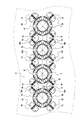
次に、本実施形態に係る配管振止め装置1を、主管2に対して設ける場合の設置方法について説明する。図6は、本実施形態において、並べて設置された主管2に配管振止め装置1が設置された様子を示す平面図である。図では並べて設置された4本の主管2に対して配管振止め装置1が設置された状態が示されている。ここで、本実施形態では、1本の主管2に対して8の緩衝材30が設置され、これらの8の緩衝材30を支持するために、4つのアーム部10が主管2を囲む構成となっている。
Next, the installation method in the case of providing the
ベース部20は、隣り合う主管2に挟まれた領域には固定されず、隣り合う2本の主管2に挟まれた領域の中心から、外側にずれた位置に固定される。ベース部20をこのような位置に固定することで、隣り合う主管2の外周同士が最も近づく部分の間(隣り合う主管2の軸同士を結ぶ面が通る位置)にベース部20が固定されることが無く、主管2同士の間隔を狭くすることが出来る。即ち、本実施形態によれば、主管2を従来に比べてより密集させて設置することが可能となり、建物におけるパイプスペースを減らし、建物のレンタブル比を向上させることが出来る。
The
また、図6に示された設置方法では、主管2の周囲に設けられるアーム部10は、隣り合う他の主管2の周囲に設けられたアーム部10と、接合に用いられるベース部20bを共用する。換言すると、隣り合う主管2の間に設けられたベース部20b(以下、「共用ベース部20b」と称する)は、夫々の主管2に対して設けられたアーム部10の両方を接合可能な構成を有する。本実施形態では、共用ベース部20bは、隣り合う主管2に対して設けられるアーム部10の双方を接合させるために、2つの立設部22を有する。この立設部22は、互いに略90度の角度で交差する方向を向くことで、共用ベース部20bを挟んで夫々反対側にある主管2のためのアーム部10が接合されることを可能としている。
In the installation method shown in FIG. 6, the
本実施形態では、1本の主管2に対して4つのアーム部10によって振れ止めを行うこととしているため、アーム部10は、主管2の周囲に、主管2の軸を中心として90度毎の間隔をおいて設置される。即ち、アーム部10の接合面14は、同一の主管2に対して設けられた隣のアーム部10の接合面14に対して90度の傾きを有する。更に、本実施形態では、隣り合う主管2に挟まれた領域の中心を除く位置にベース部20、20bを固定するために、ベース部20、20bの被接合面24(アーム部10の接合面14)は、隣り合う主管2の軸同士を結ぶ面に対して略45傾いて設置される。このため、隣り合う主管2に対して設けられたアーム部10が共用する共用ベース部20bに設けられる2つの被接合面24(立設部22)は、互いに90度の角度をもって設けられることとなる。但し、この構成は1本の主管2に対して4つのアーム部10によって振れ止めを行うこと
とした場合に、最もパイプスペースを節約できる構成であり、具体的な設置の態様には、実施の形態によって適宜最適な設置態様が選択されてよい。
In the present embodiment, the four
本実施形態によれば、少ない部品点数、および少ないコストで、十分な強度が得られる配管振止め装置を提供することが可能である。また、現場設置時に溶接作業が発生せず、形鋼等の長物の鋼材搬入を行う必要がない。加えて、本実施形態に係る配管振止め装置1は、従来の支持枠や枠部材を備えた同種装置と異なり、ベース部20が分割されて独立しているため、配管施工前に枠を取り付ける必要があった従来技術と異なり、配管施工後にも適時設置を行うことが出来る。また、配管施工前の枠の設置と、配管施工後の防振ゴム等の設置との2段階の施工が必要であった従来技術に比べて、施工段階が1回となるため、作業コストが低減されるという効果も得ることが出来る。
According to this embodiment, it is possible to provide a piping anti-vibration device that can obtain sufficient strength with a small number of parts and low cost. In addition, no welding work occurs at the time of installation on the site, and there is no need to carry in a long steel material such as a shape steel. In addition, the piping
1 配管振止め装置
10 アーム部
14 接合面
20 ベース部
24 被接合面
30 緩衝材
DESCRIPTION OF
Claims (6)
該配管振止め装置が設置された状態で、前記主管の外周の一部に面するように配置される緩衝材と、
前記緩衝材を支持し、摩擦接合のための接合面を有するアーム部と、
前記主管の近傍の床に固定され、前記アーム部を接合するために前記接合面と摩擦接合される被接合面を有するベース部と、を備え、
摩擦接合された前記接合面および被接合面は、前記主管の軸を通る面と略一致する、配管振止め装置。 A piping anti-vibration device used for anti-vibration of a main pipe installed in a building,
A cushioning material arranged to face a part of the outer periphery of the main pipe in a state where the pipe anti-vibration device is installed;
An arm portion that supports the cushioning material and has a joining surface for friction joining;
A base portion fixed to the floor in the vicinity of the main pipe and having a surface to be joined that is frictionally joined to the joint surface to join the arm portion;
The piping anti-vibration device, wherein the joint surface and the surface to be joined that are friction-joined substantially coincide with a surface that passes through the axis of the main pipe.
請求項1に記載の配管振止め装置。 The distance between the cushioning material and the main pipe is adjusted by the joining position of the joining surface and the joined surface,
The piping anti-vibration device according to claim 1.
前記ベース部は、前記高力ボルトの締結位置を前記主管の径方向において調整可能なボルト孔を有する、
請求項2に記載の配管振止め装置。 The bonded surface and the bonded surface are friction bonded using a high-strength bolt,
The base portion has a bolt hole capable of adjusting a fastening position of the high-strength bolt in a radial direction of the main pipe.
The piping anti-vibration device according to claim 2.
請求項1から3の何れか一項に記載の配管振止め装置。 The base portion has a plurality of surfaces to be joined for joining a plurality of the arm portions used for swinging a plurality of main pipes installed adjacent to each other.
The piping anti-vibration device according to any one of claims 1 to 3.
請求項4に記載の配管振止め装置。 The base part to which a plurality of the arm parts used for shaking the two main pipes installed adjacent to each other is sandwiched between the two main pipes in the floor near the two main pipes. Fixed at a position shifted to the outside of the center of the region,
The piping anti-vibration device according to claim 4.
請求項1から5の何れか一項に記載の配管振止め装置。 The arm portion includes a joint portion provided with the joint surface, and a cushioning material installation portion joined to one end of the joint portion and provided with a plurality of the cushioning materials.
The piping anti-vibration device according to any one of claims 1 to 5.
Priority Applications (1)
| Application Number | Priority Date | Filing Date | Title |
|---|---|---|---|
| JP2008193693A JP5508696B2 (en) | 2008-07-28 | 2008-07-28 | Piping brace |
Applications Claiming Priority (1)
| Application Number | Priority Date | Filing Date | Title |
|---|---|---|---|
| JP2008193693A JP5508696B2 (en) | 2008-07-28 | 2008-07-28 | Piping brace |
Publications (2)
| Publication Number | Publication Date |
|---|---|
| JP2010031940A true JP2010031940A (en) | 2010-02-12 |
| JP5508696B2 JP5508696B2 (en) | 2014-06-04 |
Family
ID=41736650
Family Applications (1)
| Application Number | Title | Priority Date | Filing Date |
|---|---|---|---|
| JP2008193693A Active JP5508696B2 (en) | 2008-07-28 | 2008-07-28 | Piping brace |
Country Status (1)
| Country | Link |
|---|---|
| JP (1) | JP5508696B2 (en) |
Cited By (1)
| Publication number | Priority date | Publication date | Assignee | Title |
|---|---|---|---|---|
| JP2015010690A (en) * | 2013-07-01 | 2015-01-19 | 株式会社神戸製鋼所 | Vibration reduction structure of pipeline and construction machine including the same |
Citations (19)
| Publication number | Priority date | Publication date | Assignee | Title |
|---|---|---|---|---|
| JPS4738285U (en) * | 1971-05-24 | 1972-12-27 | ||
| JPS534409U (en) * | 1976-06-30 | 1978-01-17 | ||
| JPS5559885U (en) * | 1978-10-18 | 1980-04-23 | ||
| JPS5748372U (en) * | 1980-09-01 | 1982-03-18 | ||
| JPS6250386U (en) * | 1985-08-31 | 1987-03-28 | ||
| JPH0231655Y2 (en) * | 1985-02-07 | 1990-08-27 | ||
| JPH0349487U (en) * | 1989-09-20 | 1991-05-14 | ||
| JPH0577065A (en) * | 1991-09-17 | 1993-03-30 | Daifuku Co Ltd | Method for joining steel material for building |
| JPH093656A (en) * | 1995-06-20 | 1997-01-07 | Tomoe Corp | Treating agent for friction joint surface of high tension bolt of galvanized structure |
| JPH1018423A (en) * | 1996-07-08 | 1998-01-20 | Nippon Steel Corp | High-strength bolt frictional joining structure using intermediate auxiliary material |
| JPH10141544A (en) * | 1996-09-12 | 1998-05-29 | Noriatsu Kojima | Pipe supporting tool |
| JP2000081168A (en) * | 1998-07-06 | 2000-03-21 | Shigero Sasamoto | Pipe fixture |
| JP2002130535A (en) * | 2000-10-17 | 2002-05-09 | Nichiei Intec Co Ltd | Piping support fitting and piping support structure using the same |
| JP2003148655A (en) * | 2001-11-14 | 2003-05-21 | Sekisui Chem Co Ltd | Vibration isolating supporting tool for piping member |
| JP2003207172A (en) * | 2002-01-18 | 2003-07-25 | Inaba Denki Sangyo Co Ltd | Fixing support device for vertical piping for air conditioning |
| JP2004027508A (en) * | 2002-06-21 | 2004-01-29 | Noriatsu Kojima | Metal support for drain pipe joint |
| JP2004156256A (en) * | 2002-11-05 | 2004-06-03 | Nichiei Intec Co Ltd | Drainage collecting pipe supporting fitting |
| JP2005240969A (en) * | 2004-02-27 | 2005-09-08 | Kubota Corp | Method of regenerating existing tube |
| JP2007255591A (en) * | 2006-03-23 | 2007-10-04 | Inaba Denki Sangyo Co Ltd | Fixedly supporting device of vertical piping for air conditioning |
-
2008
- 2008-07-28 JP JP2008193693A patent/JP5508696B2/en active Active
Patent Citations (19)
| Publication number | Priority date | Publication date | Assignee | Title |
|---|---|---|---|---|
| JPS4738285U (en) * | 1971-05-24 | 1972-12-27 | ||
| JPS534409U (en) * | 1976-06-30 | 1978-01-17 | ||
| JPS5559885U (en) * | 1978-10-18 | 1980-04-23 | ||
| JPS5748372U (en) * | 1980-09-01 | 1982-03-18 | ||
| JPH0231655Y2 (en) * | 1985-02-07 | 1990-08-27 | ||
| JPS6250386U (en) * | 1985-08-31 | 1987-03-28 | ||
| JPH0349487U (en) * | 1989-09-20 | 1991-05-14 | ||
| JPH0577065A (en) * | 1991-09-17 | 1993-03-30 | Daifuku Co Ltd | Method for joining steel material for building |
| JPH093656A (en) * | 1995-06-20 | 1997-01-07 | Tomoe Corp | Treating agent for friction joint surface of high tension bolt of galvanized structure |
| JPH1018423A (en) * | 1996-07-08 | 1998-01-20 | Nippon Steel Corp | High-strength bolt frictional joining structure using intermediate auxiliary material |
| JPH10141544A (en) * | 1996-09-12 | 1998-05-29 | Noriatsu Kojima | Pipe supporting tool |
| JP2000081168A (en) * | 1998-07-06 | 2000-03-21 | Shigero Sasamoto | Pipe fixture |
| JP2002130535A (en) * | 2000-10-17 | 2002-05-09 | Nichiei Intec Co Ltd | Piping support fitting and piping support structure using the same |
| JP2003148655A (en) * | 2001-11-14 | 2003-05-21 | Sekisui Chem Co Ltd | Vibration isolating supporting tool for piping member |
| JP2003207172A (en) * | 2002-01-18 | 2003-07-25 | Inaba Denki Sangyo Co Ltd | Fixing support device for vertical piping for air conditioning |
| JP2004027508A (en) * | 2002-06-21 | 2004-01-29 | Noriatsu Kojima | Metal support for drain pipe joint |
| JP2004156256A (en) * | 2002-11-05 | 2004-06-03 | Nichiei Intec Co Ltd | Drainage collecting pipe supporting fitting |
| JP2005240969A (en) * | 2004-02-27 | 2005-09-08 | Kubota Corp | Method of regenerating existing tube |
| JP2007255591A (en) * | 2006-03-23 | 2007-10-04 | Inaba Denki Sangyo Co Ltd | Fixedly supporting device of vertical piping for air conditioning |
Cited By (1)
| Publication number | Priority date | Publication date | Assignee | Title |
|---|---|---|---|---|
| JP2015010690A (en) * | 2013-07-01 | 2015-01-19 | 株式会社神戸製鋼所 | Vibration reduction structure of pipeline and construction machine including the same |
Also Published As
| Publication number | Publication date |
|---|---|
| JP5508696B2 (en) | 2014-06-04 |
Similar Documents
| Publication | Publication Date | Title |
|---|---|---|
| JP4972567B2 (en) | Seismic ceiling structure and installation method | |
| KR101654338B1 (en) | Column type vibration isolation apparatus | |
| KR102234316B1 (en) | Facility piping hanger with improved seismic performance | |
| JP2017226989A (en) | Junction structure, junction method and junction metal fitting | |
| JP6247870B2 (en) | Seismic reduction device | |
| JP2015116087A (en) | Seismic control structure of cable support material | |
| JP6216552B2 (en) | Vibration suppression suspension structure | |
| JP5508696B2 (en) | Piping brace | |
| JP2009068210A (en) | Vibration control structure of building | |
| KR101946985B1 (en) | Panel pipe support device for sound proof tunnel | |
| JP2008267524A (en) | Vibration absorbing base device | |
| CN210890395U (en) | Anti-seismic support is stabilized to high strength | |
| JP4824476B2 (en) | Seismic isolation devices and seismic isolation structures for buildings | |
| CN212957194U (en) | Connecting device | |
| JP2006022483A (en) | Earthquake resistant structure of suspended ceiling | |
| JP6925114B2 (en) | Connection structure | |
| JP2011169026A (en) | Floor structure | |
| JP5869309B2 (en) | Ceiling suspended seismic reduction device | |
| JP2005146780A (en) | Mounting metal piece | |
| JP2007077572A (en) | Seismic control structure of building | |
| KR101654337B1 (en) | Column type vibration isolation apparatus | |
| JP7224037B2 (en) | Ceiling frame suspension structure | |
| JP4361426B2 (en) | bracket | |
| CN220623198U (en) | Floor type air pipe shock-absorbing bracket | |
| CN219673505U (en) | Pipeline bearing support with damping device |
Legal Events
| Date | Code | Title | Description |
|---|---|---|---|
| A621 | Written request for application examination |
Free format text: JAPANESE INTERMEDIATE CODE: A621 Effective date: 20110616 |
|
| A977 | Report on retrieval |
Free format text: JAPANESE INTERMEDIATE CODE: A971007 Effective date: 20121214 |
|
| A131 | Notification of reasons for refusal |
Free format text: JAPANESE INTERMEDIATE CODE: A131 Effective date: 20130108 |
|
| A521 | Written amendment |
Free format text: JAPANESE INTERMEDIATE CODE: A523 Effective date: 20130308 |
|
| A131 | Notification of reasons for refusal |
Free format text: JAPANESE INTERMEDIATE CODE: A131 Effective date: 20130917 |
|
| A521 | Written amendment |
Free format text: JAPANESE INTERMEDIATE CODE: A523 Effective date: 20131017 |
|
| TRDD | Decision of grant or rejection written | ||
| A01 | Written decision to grant a patent or to grant a registration (utility model) |
Free format text: JAPANESE INTERMEDIATE CODE: A01 Effective date: 20140304 |
|
| A61 | First payment of annual fees (during grant procedure) |
Free format text: JAPANESE INTERMEDIATE CODE: A61 Effective date: 20140324 |
|
| R150 | Certificate of patent or registration of utility model |
Ref document number: 5508696 Country of ref document: JP Free format text: JAPANESE INTERMEDIATE CODE: R150 |