JP2010031647A - Internal excavation method through pile, and foundation pile structure - Google Patents
Internal excavation method through pile, and foundation pile structure Download PDFInfo
- Publication number
- JP2010031647A JP2010031647A JP2009261392A JP2009261392A JP2010031647A JP 2010031647 A JP2010031647 A JP 2010031647A JP 2009261392 A JP2009261392 A JP 2009261392A JP 2009261392 A JP2009261392 A JP 2009261392A JP 2010031647 A JP2010031647 A JP 2010031647A
- Authority
- JP
- Japan
- Prior art keywords
- pile
- ready
- tip
- ground
- excavation
- Prior art date
- Legal status (The legal status is an assumption and is not a legal conclusion. Google has not performed a legal analysis and makes no representation as to the accuracy of the status listed.)
- Granted
Links
- 238000009412 basement excavation Methods 0.000 title claims abstract description 154
- 238000000034 method Methods 0.000 title claims abstract description 67
- 239000002689 soil Substances 0.000 claims abstract description 112
- 239000004568 cement Substances 0.000 claims abstract description 65
- 238000013461 design Methods 0.000 claims abstract description 12
- 230000007246 mechanism Effects 0.000 claims abstract description 11
- 238000005553 drilling Methods 0.000 claims description 31
- 238000010008 shearing Methods 0.000 claims description 13
- 230000000644 propagated effect Effects 0.000 claims description 8
- 230000001902 propagating effect Effects 0.000 claims description 4
- 238000003825 pressing Methods 0.000 claims description 3
- 239000008267 milk Substances 0.000 abstract description 30
- 210000004080 milk Anatomy 0.000 abstract description 30
- 235000013336 milk Nutrition 0.000 abstract description 30
- 239000002184 metal Substances 0.000 description 25
- 229910000831 Steel Inorganic materials 0.000 description 21
- 239000010959 steel Substances 0.000 description 21
- 238000007596 consolidation process Methods 0.000 description 19
- 238000010276 construction Methods 0.000 description 18
- 230000001965 increasing effect Effects 0.000 description 15
- 230000015572 biosynthetic process Effects 0.000 description 14
- 238000005755 formation reaction Methods 0.000 description 14
- 238000007711 solidification Methods 0.000 description 13
- 230000008023 solidification Effects 0.000 description 13
- 230000002093 peripheral effect Effects 0.000 description 12
- 238000003756 stirring Methods 0.000 description 10
- 230000035515 penetration Effects 0.000 description 6
- 238000007599 discharging Methods 0.000 description 5
- 239000007788 liquid Substances 0.000 description 5
- 238000013019 agitation Methods 0.000 description 4
- 239000003795 chemical substances by application Substances 0.000 description 4
- 230000008569 process Effects 0.000 description 4
- 238000012360 testing method Methods 0.000 description 4
- 238000013459 approach Methods 0.000 description 2
- 230000000694 effects Effects 0.000 description 2
- 238000002347 injection Methods 0.000 description 2
- 239000007924 injection Substances 0.000 description 2
- 238000011068 loading method Methods 0.000 description 2
- 239000000463 material Substances 0.000 description 2
- 238000002156 mixing Methods 0.000 description 2
- 230000009467 reduction Effects 0.000 description 2
- 239000003381 stabilizer Substances 0.000 description 2
- 239000000853 adhesive Substances 0.000 description 1
- 230000001070 adhesive effect Effects 0.000 description 1
- 238000007664 blowing Methods 0.000 description 1
- 230000000052 comparative effect Effects 0.000 description 1
- 230000001276 controlling effect Effects 0.000 description 1
- 238000005520 cutting process Methods 0.000 description 1
- 230000003247 decreasing effect Effects 0.000 description 1
- 230000002708 enhancing effect Effects 0.000 description 1
- 230000007613 environmental effect Effects 0.000 description 1
- 238000002474 experimental method Methods 0.000 description 1
- 238000000605 extraction Methods 0.000 description 1
- 238000007429 general method Methods 0.000 description 1
- 238000000227 grinding Methods 0.000 description 1
- 230000006872 improvement Effects 0.000 description 1
- 238000007373 indentation Methods 0.000 description 1
- 238000012966 insertion method Methods 0.000 description 1
- 238000009434 installation Methods 0.000 description 1
- 238000011835 investigation Methods 0.000 description 1
- 238000004898 kneading Methods 0.000 description 1
- 238000012423 maintenance Methods 0.000 description 1
- 238000004519 manufacturing process Methods 0.000 description 1
- 230000001105 regulatory effect Effects 0.000 description 1
- 230000002787 reinforcement Effects 0.000 description 1
- 230000008439 repair process Effects 0.000 description 1
- 238000003466 welding Methods 0.000 description 1
Images


Classifications
-
- E—FIXED CONSTRUCTIONS
- E02—HYDRAULIC ENGINEERING; FOUNDATIONS; SOIL SHIFTING
- E02D—FOUNDATIONS; EXCAVATIONS; EMBANKMENTS; UNDERGROUND OR UNDERWATER STRUCTURES
- E02D5/00—Bulkheads, piles, or other structural elements specially adapted to foundation engineering
- E02D5/22—Piles
- E02D5/62—Compacting the soil at the footing or in or along a casing by forcing cement or like material through tubes
Abstract
Description
本発明は、杭穴を掘削しつつ既製杭を埋設する中掘工法、この工法に基づき施工された杭穴内に既製杭を埋設してなる基礎杭構造に関する。とりわけ、地盤途中に比較的軟弱な地盤の層を含み、その層では十分な支持力が得られない場合に特に有効である。 The present invention relates to an intermediate excavation method in which a ready-made pile is buried while excavating a pile hole, and a foundation pile structure in which the ready-made pile is buried in a pile hole constructed based on this method. In particular, it is particularly effective when a relatively soft ground layer is included in the middle of the ground, and sufficient supporting force cannot be obtained with that layer.
一般的な杭の中掘工法では、既製杭の中空部に、掘削ヘッドおよび排土スパイラルを形成した掘削ロッドを挿入して、既製杭の先に突出した掘削ロッドで、地層を掘削しながら、既製杭を沈設させていた。この場合、掘削ヘッドの掘削径は、埋設する既製杭の内径より若干小さい(マイナス40mm程度)寸法としていた(非特許文献1)。そして、この杭穴内にそのまま既製杭を押し込め、あるいは杭穴内壁と既製杭の隙間にセメントミルクを注入して既製杭を押し込めていた(例えば、特許文献1、5頁左上より2〜3行目)。
In the general method of excavating piles, the excavation head and the excavation rod that forms the earth removal spiral are inserted into the hollow part of the ready-made pile, and the excavation rod that protrudes beyond the ready-made pile is excavating the formation, Ready-made piles were sunk. In this case, the excavation diameter of the excavation head is set to be slightly smaller (about minus 40 mm) than the inner diameter of the ready-made pile to be embedded (Non-Patent Document 1). And, the ready-made pile was pushed into the pile hole as it was, or cement milk was poured into the gap between the inner wall of the pile hole and the ready-made pile, and the ready-made pile was pushed in (for example,
また、中掘工法で、根固め部を拡径して、先端支持力を増加させる場合、掘削ヘッドに揺動して拡大掘削できる掘削刃(特許文献1)や掘削ロッドの軸に直交する方向(水平方向)に突出する掘削刃を形成して、拡大根固め部の掘削をしていた。 Also, in the case of increasing the diameter of the root-sealed part and increasing the tip support force by the medium digging method, the direction perpendicular to the axis of the excavating blade (Patent Document 1) or the excavating rod that can be expanded and excavated by swinging the excavating head Excavation blades protruding in the (horizontal direction) were formed, and the enlarged root was excavated.
また、既製杭の埋設に先立ち、掘削ロッドで杭穴の全部を掘削した後に既製杭を埋設して基礎杭を埋設する工法(先掘工法)では、掘削ロッドの中間部に拡開刃を形成して、杭穴の軸部に拡径部を掘削する工法も提案されているが(特許文献2)、軟らかい地層等では採用できず、使用範囲が限られていた。 In addition, prior to laying the ready-made pile, in the method of digging all of the pile holes with the excavating rod and then burying the ready-made pile and burying the foundation pile (the pre-excavation method), an expanding blade is formed in the middle part of the excavating rod And although the construction method which excavates a diameter-expansion part to the axial part of a pile hole is proposed (patent document 2), it cannot employ | adopt with a soft geological formation etc., but the use range was limited.
また、中掘工法では、上記のように、既製杭の外径より小さな径の杭穴を掘削するので、先掘工法で使用するような、外側面に節などの凹凸を形成した既製杭を使用することができず、専ら円筒形状の既製杭を使用していた。 In addition, as described above, in the medium excavation method, a pile hole having a diameter smaller than the outer diameter of the ready-made pile is excavated. It was not possible to use it, and it was exclusively using pre-made cylindrical piles.
また、排土を減らすことを目的とした発明として、特許文献3〜5が開示されている。
(1) いわゆる先掘工法では、既製杭の埋設に先立ち、杭穴の全部を掘削した後に既製杭を埋設して、掘削ドラムで杭穴壁を均してセメントミルクを撹拌・充填できるが、中掘工法では、一般に、掘削土の大部分を掘削ロッドで排出しており、更に構造上から掘削ロッドに練付ドラムを取付け難いので、杭穴壁を均すこともできなった。従って、既製杭と杭穴との間の杭周部を支持力として十分に利用できなかった。 (1) In the so-called pre-drilling method, prior to the laying of ready-made piles, after excavating all the pile holes, the pre-made piles can be buried, and the pile hole walls can be leveled with a drilling drum to stir and fill cement milk. In the medium excavation method, in general, most of the excavated soil is discharged by the excavating rod, and it is difficult to attach the kneading drum to the excavating rod from the structure. Therefore, the pile peripheral part between a ready-made pile and a pile hole was not fully able to be utilized as a supporting force.
また、中掘用の掘削ロッドでは、既製杭(通常はコンクリート系)の中空部を通過させなければならないという構造上の制限があり、比較的拡径が容易な場合(特許文献2)でも、中空部通過状態(最小径)、杭穴軸部掘削状態(中間径)、杭穴拡底部掘削状態(最大径)の3位置を取らなければならず、複雑な構造で設計強度上限られていた。また、通常の掘削径の2段切替式では、拡底根固め部を形成する場合には、根固め部の掘削径は、杭穴の軸部径の1.2倍程度までであり、前記掘削ヘッドに掘削刃付きの揺動腕を設けた場合であっても、1.5倍が限度であった。特に外径1000φ等の大径の既製杭を使用した場合には、1.2倍程度に制限されていた。 In addition, in the excavation rod for medium digging, there is a structural limitation that the hollow portion of the ready-made pile (usually concrete system) has to pass, even when the diameter expansion is relatively easy (Patent Document 2), It had to take three positions: a hollow part passing state (minimum diameter), a pile hole shaft excavating state (intermediate diameter), and a pile hole widening part excavating state (maximum diameter), and the design strength was limited by a complicated structure. . Further, in the normal two-stage switching type of the excavation diameter, when forming the bottomed root consolidation part, the excavation diameter of the root consolidation part is up to about 1.2 times the shaft diameter of the pile hole. Even when a swing arm with an excavating blade was provided on the head, the limit was 1.5 times. In particular, when a large-diameter ready-made pile such as an outer diameter of 1000φ was used, it was limited to about 1.2 times.
また、中堀工法では、一般に掘削ヘッドの直上に既製杭の先端を位置させて、該既製杭を沈設しながら掘削するので、前記特許文献2のように掘削ロッドの中間部に拡径刃を形成して拡径部を掘削することができなかった。
Further, in the Nakabori method, generally, the tip of the ready-made pile is positioned immediately above the excavation head, and excavation is performed while the ready-made pile is submerged. Therefore, as in
従って、中掘工法では、掘削速度を速くするためには、掘削土の排出を多くせざるを得ず、結果として環境面からも好ましくなく、施工する土質も限られていた。即ち、掘削土の排出を良くするため各種の工夫が成されていた(日本国.特開平5−3353号公報の空気の吹き出し等)。 Therefore, in the medium excavation method, in order to increase the excavation speed, it is necessary to increase the discharge of excavated soil. As a result, it is not preferable from the environmental viewpoint, and the soil quality to be constructed is limited. That is, various ideas have been made to improve the discharge of excavated soil (Japan, Japanese Patent Laid-Open No. 5-3353, such as air blowing).
(2) また、一般に、砂質土、礫質土等の地盤に、拡底根固め部を形成する中掘工法では、
総支持力Ra=1/3(Rp+Rf) (kN/本)
で、算定される。
(2) Also, in general, in the middle digging method that forms an expanded bottom solidified part in the ground such as sandy soil, gravelly soil,
Total supporting force R a = 1/3 (R p + R f ) (kN / piece)
Is calculated.
ここで、Rp=α×Nave×Ap
α:支持力定数(通常250程度)
Nave:杭先端平均N値
Ap:既製杭の先端断面積
である。尚、ここで既製杭の先端断面積は、荷重によるせん断力の伝搬に寄与するソイルセメント層との付着面積に相当する。
Here, R p = α × N ave × A p
α: Bearing capacity constant (usually around 250)
N ave: Pile tip average N values A p: is the tip cross-sectional area of the ready-made pile. Here, the tip cross-sectional area of the ready-made pile corresponds to the adhesion area with the soil cement layer that contributes to the propagation of the shearing force due to the load.
また、Rfは、杭周面摩擦抵抗力で、杭周固定液の使用の有無により、
・杭周固定液使用時: Rf=C×Nave×L×φ
(C=2〜3)
・杭周固定液不使用時:Rf=C×L×φ
(C=15)
の値を使用する。
Also, R f is the pile surface frictional resistance, depending on whether or not the pile circumference fixing liquid is used,
・ When using pile circumference fixing liquid: R f = C × N ave × L × φ
(C = 2 to 3)
・ When not using pile circumference fixing liquid: R f = C × L × φ
(C = 15)
Use the value of.
また、ここで、
L:杭の周面摩擦力を考慮し得る地盤の長さ
φ:杭の周長
Nave:杭周固定液を使用する区間の平均N値
である。
Also here
L: Length of the ground which can consider the peripheral frictional force of the pile φ: Perimeter of the pile N ave : Average N value of the section using the pile circumference fixing liquid.
総じて、N値が低い場合(例えば10以下)は、既製杭として通常の円筒杭を使用した場合は、節杭など利用した基礎杭構造に比べRf(杭周面摩擦抵抗力)が小さくなっていた。 In general, when the N value is low (for example, 10 or less), when an ordinary cylindrical pile is used as an off-the-shelf pile, R f (pile circumferential surface frictional resistance) is smaller than that of a foundation pile structure such as a joint pile. It was.
従って、中掘工法において、支持力を増加する為には、Rp、Rfのいずれか又は両方を増加させることが必要であった。 Therefore, in the medium excavation method, it is necessary to increase either or both of R p and R f in order to increase the bearing capacity.
この発明では、Rfを大きくするために、杭穴の軸部外周部を改良して、既製杭の周面全体として地盤強度を向上させることを目的とする。これにより、既製杭の周面の全体的な摩擦抵抗力を確保・増加させると共に、応力伝搬面積を大きくして応力が広く緩和して伝搬できるようにする。即ち、上記Rfの式において、Nあるいは係数C等を大きくする。 In this invention, in order to enlarge Rf , it aims at improving the ground strength as the whole peripheral surface of a ready-made pile by improving the axial part outer peripheral part of a pile hole. As a result, the overall frictional resistance of the peripheral surface of the ready-made pile is secured and increased, and the stress propagation area is increased so that the stress can be widely relaxed and propagated. That is, in the above formula of R f , N or the coefficient C is increased.
(3) また、Rp(先端支持力)を増強するために、杭下端部(先端部)の杭外表面を広くしソイルセメントとの付着面積を増強すると共に、付着面よりの応力が充分に伝搬できる高固化強度の根固め部を形成することを目的とする。即ち、上記式において、α及びApを大きくする。 (3) Also, in order to increase R p (tip support force), the pile outer surface at the lower end of the pile (tip) is widened to increase the adhesion area with the soil cement, and there is sufficient stress from the adhesion surface. The purpose is to form a solidified portion with high solidification strength that can be propagated to the surface. That is, in the above formula, α and Ap are increased.
また、この発明は、中掘工法において、杭穴掘削時に、既製杭の中空部より地上に排出される排土を少なくすることを目的とする。 Another object of the present invention is to reduce the amount of soil discharged to the ground from the hollow portion of a ready-made pile during excavation of a pile hole in the medium excavation method.
(4) また、特許文献3の発明は、予め先端に地中にねじ込みできかつ補強となる金具を付けた鋼管を、ケーシングとして地中にねじ込み、その後鋼管内に、既製杭(コンクリート製)を挿入する工法で、排土の削減を実現する発明が開示されている。しかし、この工法では、既製杭を金具に載せただけであり、既製杭と金具の一体性が無く、更に地盤と既製杭との間の応力伝搬を確実にするソイルセメント層などの固化混合層の配慮が無く、高支持力の発揮は期待できない。また、この工法は、金具を必須としているので、中掘工法への応用は一切できない。
(4) In addition, the invention of
また、特許文献4の発明は、既製杭の外径と等しい径の杭穴を掘削し、その後らせん翼を有する既製杭を埋設する先掘工法である。杭穴の軸部の径を相対的に小さくすることにより、掘削土の排出量を軽減する点が開示されている。しかし、特許文献4の発明は、らせん翼をねじ込む際に、大きなねじれが既製杭に生じ、地盤が固い場合には特に既製杭に巨大なねじれが生じ、コンクリート製の既製杭では実施不可能である。また、地層に軟らかい層が含まれている場合には、杭穴径が小さいので、杭穴壁と既製杭の外側面との隙間にセメントミルク等と固化混合層の形成ができ難いので、周辺摩擦力の発揮が困難である。 Moreover, invention of patent document 4 is a pre-digging method which excavates the pile hole of the diameter equal to the outer diameter of a ready-made pile, and embeds the ready-made pile which has a spiral blade after that. The point which reduces the discharge | emission amount of excavated soil by making the diameter of the axial part of a pile hole relatively small is disclosed. However, in the invention of Patent Document 4, when twisting the spiral wing, a large twist occurs in the ready-made pile, and especially when the ground is hard, a huge twist occurs in the ready-made pile. is there. Also, if the stratum contains a soft layer, the pile hole diameter is small, so it is difficult to form a solidified mixed layer such as cement milk in the gap between the pile hole wall and the outer surface of the ready-made pile. It is difficult to exert frictional force.
また、特許文献5の発明は、中空の既製杭の下端部にらせん翼と掘削刃を有する推進ヘッドを嵌め合わせて、既製杭を通した回転ロッドで推進ヘッドを回転して、既製杭を無回転で貫入させる工法が開示されている。しかし、特許文献5の発明は、埋設される推進ヘッドと既製杭との一体性が不確実で、また拡大掘削ができないので、推進ヘッドを使った有効な支持地盤周辺での支持力強化が図れない。また、中間深さの地層に軟らかい層が含まれている場合には、その部分での固化混合層の形成ができず、周辺摩擦力の強化が図れない。更に、複雑な構造の推進ヘッドを支持地盤から回収できず、コストを要する。 In addition, the invention of Patent Document 5 is such that a propulsion head having a spiral blade and an excavating blade is fitted to the lower end of a hollow prefabricated pile, and the propulsion head is rotated with a rotating rod passing through the prefabricated pile, so that the prefabricated pile is not used. A method of making it penetrate by rotation is disclosed. However, in the invention of Patent Document 5, since the integrity of the buried propulsion head and the ready-made pile is uncertain and expansion excavation is not possible, it is possible to enhance the bearing capacity around the effective support ground using the propulsion head. Absent. In addition, when a soft layer is included in the formation at an intermediate depth, a solidified mixed layer cannot be formed at that portion, and the peripheral frictional force cannot be enhanced. Furthermore, the propulsion head having a complicated structure cannot be recovered from the supporting ground, and costs are required.
前記課題を解決するために、この発明では、杭穴軸部も含めて、従来に比べて掘削径の大きい(既製杭の杭径に対して)杭穴を掘削し、更に当該杭穴の掘削中に、少なくとも設計上望ましい深度範囲の適宜区間に固化混合層を形成しつつ杭穴を掘削する構成とした。 In order to solve the above-mentioned problems, in the present invention, a pile hole having a larger excavation diameter (with respect to a pile diameter of an already-made pile) is also excavated including the shaft portion of the pile hole, and further excavation of the pile hole is performed. The pile hole was excavated while forming a solidified mixed layer in an appropriate section at least in the desired depth range in design.
即ち、第1の発明は、既製杭の中空部の先端から掘削ロッドの掘削ヘッドを突出させ、地盤を掘削して杭穴を形成しつつ既製杭を下降して、所定杭穴内に前記既製杭を埋設する杭の中掘工法において、スパイラル等の排土機構を有しない掘削ロッドを使用して、地盤をほぐしながら杭穴を掘削し、ほぐした掘削土を、前記既製杭の外面で外側に押し固めながら、前記既製杭を沈設することを特徴とした杭の中掘工法である。 That is, in the first invention, the drilling head of the drilling rod protrudes from the tip of the hollow part of the ready-made pile, the ready-made pile is lowered while excavating the ground to form the pile hole, and the ready-made pile is placed in the predetermined pile hole. In the middle excavation method for piles, the excavation rods that do not have a soil removal mechanism such as a spiral are used to excavate the pile holes while loosening the ground, and the loose excavated soil is exposed to the outside on the outer surface of the ready-made piles. It is a pile digging method characterized in that the ready-made pile is sunk while being compacted.
また、第2の発明は、既製杭の中空部の先端から掘削ロッドの掘削ヘッドを突出させ、地盤を掘削して杭穴を形成しつつ既製杭を下降して、所定杭穴内に前記既製杭を埋設する杭の中掘工法において、地盤をほぐしながら杭穴を掘削し、ほぐした掘削土を、前記既製杭の外面で外側に押し固めながら、前記既製杭を沈設することを特徴とした杭の中掘工法である。 Moreover, 2nd invention makes a digging head of a digging rod protrude from the front-end | tip of the hollow part of a ready-made pile, descend | falls a ready-made pile while excavating the ground and forming a pile hole, The said ready-made pile is put in a predetermined pile hole. In the medium excavation method for piles, the piles are excavated while the ground is loosened, and the ready-made piles are submerged while the loosened excavated soil is pressed outward on the outer surface of the ready-made piles. This is the middle digging method.
また、第3の発明は、既製杭の中空部の先端から掘削ロッドの掘削ヘッドを突出させ、地盤を掘削して杭穴を形成しつつ既製杭を下降して、所定杭穴内に前記既製杭を埋設する杭の中掘工法において、スパイラル等の排土機構を有しない掘削ロッドを使用し、当該地盤中で、設計で定めた所定の深度範囲を、地盤をほぐしながら杭穴を掘削し、ほぐした掘削土を、前記既製杭の外面で外側に押し固めることを特徴とした杭の中掘工法である。 Moreover, 3rd invention makes a digging head of a digging rod protrude from the front-end | tip of the hollow part of a ready-made pile, descend | falls a ready-made pile while excavating the ground to form a pile hole, and the said ready-made pile is put in a predetermined pile hole. In the method of digging piles to bury the pile, use a drilling rod that does not have a soil removal mechanism such as a spiral, and in the ground, excavate a pile hole while loosening the ground within a predetermined depth range determined by design, The pile digging method is characterized in that loosened excavated soil is pressed outward by the outer surface of the ready-made pile.
また、前記各発明において、既製杭の先端に先端金具を連結して、該先端金具の先端から掘削ヘッドを突出して、地盤を掘削して杭穴を形成し、前記先端金具は、杭穴内に形成したソイルセメント層内に位置し、前記先端金具は筒状基部の外側面に1つ又は複数箇所に支持面を形成し、該支持面は、垂直面に対して傾斜した面であって、前記ソイルセメント層に向けて、上方又は下方のせん断力を伝搬させ先端支持力として利用することができる構成としたことを特徴とした杭の中掘工法とすることが望ましい。また、杭軸部の下端部外側面に凹凸部を形成した既製杭を使用して、該既製杭の先端から掘削ヘッドを突出して、地盤を掘削して杭穴を形成し、前記既製杭の凹凸部は、前記既製杭の下端部外側面に、上方又は下方に向けて、せん断力を伝搬させ先端支持力として利用することができる支持面を、1つ又は複数箇所に形成することを特徴とした杭の中掘工法とすることが望ましい。また、既製杭の先端に、筒状基部の外側面に横方向の突起を形成した先端金具を連結して、該先端金具の先端から掘削ヘッドを突出して、地盤を掘削して杭穴を形成することを特徴とする杭の中掘工法とすることが望ましい。また、固化混合層の外径と、杭穴の根固め部の外径とを略同一外径に形成することを特徴とした杭の中掘工法とすることが望ましい。 Further, in each of the above inventions, a tip metal fitting is connected to the tip of the ready-made pile, a drilling head is protruded from the tip of the tip fitting, a ground hole is excavated to form a pile hole, and the tip metal fitting is in the pile hole. Located in the formed soil cement layer, the tip fitting forms a support surface at one or more places on the outer surface of the cylindrical base, the support surface is a surface inclined with respect to the vertical surface, It is desirable that the pile digging method is characterized in that an upward or downward shear force can be propagated toward the soil cement layer and used as a tip support force. Moreover, using the ready-made pile which formed the uneven | corrugated | grooved part in the lower end part outer surface of a pile axial part, a drilling head protrudes from the front-end | tip of this ready-made pile, a ground is excavated, a pile hole is formed, The concavo-convex part is characterized by forming a support surface that can be used as a tip support force by propagating a shearing force upward or downward on the outer surface of the lower end of the ready-made pile at one or a plurality of locations. It is desirable to use the digging method for piles. In addition, a tip fitting with a lateral projection formed on the outer surface of the cylindrical base is connected to the tip of the ready-made pile, and the excavation head protrudes from the tip of the tip fitting to excavate the ground to form a pile hole. It is desirable to use the method of digging piles characterized by Moreover, it is desirable to use the pile digging method characterized in that the outer diameter of the solidified mixed layer and the outer diameter of the rooted portion of the pile hole are formed to have substantially the same outer diameter.
また、第4の発明は、杭穴内に既製杭を埋設して構成した基礎杭構造であって、前記杭穴は、少なくとも設計で予め定めた深度範囲の地盤強度を復元及び改良して構成し、前記既製杭は下端部に先端金具を取り付けてなり、該先端金具は、前記杭穴内に形成したソイルセメント層内に位置し、前記先端金具は筒状基部の外側面に1つ又は複数箇所に支持面を形成し、該支持面は、垂直面に対して傾斜した面であって、前記ソイルセメント層に向けて、上方又は下方のせん断力を伝搬させ先端支持力として利用することができる構成としたことを特徴とする基礎杭構造である。 Moreover, 4th invention is the foundation pile structure comprised by burying a ready-made pile in a pile hole, Comprising: The said pile hole is comprised by restoring and improving the ground strength of the depth range predetermined by design. The ready-made pile has a tip fitting attached to a lower end portion, the tip fitting is located in a soil cement layer formed in the pile hole, and the tip fitting is provided at one or more places on the outer surface of the cylindrical base. The support surface is a surface inclined with respect to a vertical surface, and can be used as a tip support force by propagating an upward or downward shear force toward the soil cement layer. It is a foundation pile structure characterized by having a configuration.
前記における比較的軟弱な地層とは、既製杭の埋設予定の地盤で、その1つの杭穴で、予め想定した地盤強度に対して、その想定した地盤強度より小さな強度しか有しない地盤強度の地盤を指す。例えば、想定する地盤強度を、砂質土において、N値で“20”とした場合、その平均N値より大幅に低い値、例えば“5”より小さな値を有するN値を有する、支持力としてほとんど考慮できない地盤を指す。この場合、予め想定する地盤強度は、1本の杭穴毎に設定される場合、あるいは敷地全体に対して設定される場合、等がある。 The relatively soft stratum in the above is the ground where the ready-made pile is to be buried, and the ground strength of the ground having only one strength lower than the assumed ground strength with respect to the ground strength assumed in advance in one of the pile holes. Point to. For example, when the assumed ground strength is “20” in sandy soil with an N value of “20”, the bearing strength has a value that is significantly lower than the average N value, for example, an N value that is smaller than “5”. It refers to the ground that can hardly be considered. In this case, the ground strength assumed in advance may be set for each pile hole or may be set for the entire site.
また、前記において、セメントミルク類とは、掘削土に混入して撹拌混合すれば、所定時間経過後に固化するセメントミルク及びセメントミルクと同等の水硬性の材料を指す。 In the above, cement milk refers to cement milk that solidifies after elapse of a predetermined time if mixed in excavated soil and mixed with stirring, and a hydraulic material equivalent to cement milk.
また、前記において、「設計で定めた所定の深度範囲」は、通常地盤は各種地盤強度の地層から形成されており、どの深度範囲を設定するかは、基礎杭構造の総体として、強度を高められる範囲を定める。即ち、軟弱な地層を「所定の深度
範囲」に定める場合、あるいは比較的地盤強度の強い中間層を「所定の深度範囲」と定める場合、軟弱の層を適宜を組み合わせて「所定の深度範囲」とする場合、あるいは、地盤強度によらず、ある深度範囲を「所定の深度範囲」に定める場合等がある。
In addition, in the above, the “predetermined depth range determined by design” is that the normal ground is formed from strata with various ground strengths, and the depth range to be set depends on the overall strength of the foundation pile structure. Determine the scope to be. That is, when a soft stratum is defined as a “predetermined depth range” or an intermediate layer having a relatively strong ground strength is defined as a “predetermined depth range”, the soft stratum is appropriately combined to form a “predetermined depth range”. In some cases, a certain depth range is defined as a “predetermined depth range” regardless of the ground strength.
また、前記において、「既製杭の外径の1.4倍以上で掘削」としたが、特に杭穴の軸部においては、上限は無く、大径とすればそれだけ既製杭の埋設は容易であり、かつ支持力の増加が期待できる。しかし、大径とすればそれだけ大きな掘削ロッドを必要とし、また掘削速度も遅くなり、施工効率が悪くなる。従って、上記及び基礎杭(既製杭)の設置間隔等を比較調整して、通常は、根固め部で高い先端支持力が得られる掘削径と同一寸法である1.4〜1.5倍程度が望ましい。 Moreover, in the above, “excavation with 1.4 times or more of the outer diameter of the ready-made pile” was made, but there is no upper limit especially in the shaft portion of the pile hole. Yes, and an increase in supportiveness can be expected. However, if the diameter is large, a larger excavation rod is required, and the excavation speed becomes slower, resulting in poor construction efficiency. Therefore, by comparing and adjusting the installation interval of the above and foundation piles (off-the-shelf piles), it is usually about 1.4 to 1.5 times the same diameter as the excavation diameter at which high tip support force can be obtained at the root consolidation part Is desirable.
また、前記における「せん断力の伝搬」とは「先端金具13を取り付けた既製杭」あるいは「下端部外側面に凹凸部を設けた既製杭」を杭穴内の固化したソイルセメント層内に埋設した場合に当該ソイルセメント層へ向けてせん断力を伝搬できることをいう。また「せん断力を伝搬させることができる支持面」は、「先端金具の筒状基部(鋼管本体)6の外側面」あるいは「既製杭の下端部外側面」に突起(例えば環状突起)10を形成した場合には、当該突起10の下面が下方に向けてせん断力を伝搬されることができる支持面Bを構成し、当該突起10の上面が上方に向けてせん断力を伝搬されることができる支持面Aを構成する(図4(a))。この場合、突起10の上下面は、垂直面に対して多少傾斜した面であることが望ましい。また、実験によれば、せん断力の伝搬する方向は、垂直面に対して斜めに作用しているので、当該伝搬する方向と直角に形成することが望ましいことが分かっている。
In addition, “propagation of shear force” in the above is “prepared pile with tip metal fitting 13” or “prefabricated pile with an uneven portion on the outer side of the lower end” embedded in a solidified soil cement layer in the pile hole. In some cases, shear force can be propagated toward the soil cement layer. Further, the “support surface capable of propagating the shearing force” includes a protrusion (for example, an annular protrusion) 10 on the “outer surface of the cylindrical base portion (steel pipe main body) 6 of the tip metal fitting” or “the lower end portion outer surface of the ready-made pile”. When formed, the lower surface of the
また、突起部を広く取るために、上下方向のせん断力の作用する支持面を筒状基部1の外側面に凹部として形成した場合には、凹部の側壁面が各支持面A、Bを構成する(図4(b))。更に、支持面は、突起や凹部に限らず、筒状基部6の外側面に段差を形成して同様の機能を有する支持面A又は支持面Bとすることもでき(図4(c)(d))、その形状は任意である。要は、筒状基部6(既製杭1に環状突起37を形成する場合には、下部軸部36。図2(a))の外側面にせん断力の伝搬に有効な何らかの手段(例えば段差部等)が形成され、先端支持力として利用できれば、凹凸の形状に関係なく支持面を構成できる。
In addition, when the support surface on which the vertical shearing force acts is formed as a recess on the outer surface of the
また、前記における筒状基部6(あるいは、下部軸部36。図2(a))は、応力の伝搬バランス上、円筒状とすることが望ましいが、角筒等その形状は任意である。
The cylindrical base portion 6 (or the
また、前記において、先端金具13の筒状基部6の外径D11は、既製杭1の外径D01より小径に形成すれば(D11≦D01)、既製杭1の外径D01に応じた杭穴を掘削すれば良いので望ましい。この場合には、筒状基部6の上端部に、既製杭1の外径D01に応じた大径部7を形成する(図2(b))。また、この場合、支持面を形成する環状突起10の外径D13を、既製杭1の外径D01(即ち、大径部7の外径)より小径とし(D13<D01)、あるいは、外径D13を既製杭1の外径D01より大径とすることもでできる(D01<D13)。また、当然、D13=D01、とすることもできる。また、外径D13をD01より大きくしない方が既製杭を挿入する際の抵抗が少ないので、高い地盤強度(あるいは土質の密度)等の地盤の施工では有効である。
Further, in the above, the outer diameter D 11 of the
また、筒状基部6の外径D11を、既製杭1の外径D01と同等とし(D01≒D11)、あるいは、筒状基部1の外径D11を、既製杭1の外径D01より大径とすることもできる(D01<D11)。これらの寸法は、地盤強度や土質の密度、基礎杭に求められる所要耐力等により使い分けることができる。
Further, the outer diameter D 11 of the
また、先端金具13を使用せずに、既製杭1に細径の下部軸部36を形成して該部に環状突起37、37を形成した場合には(図2(a))筒状基部6の外面が、下部軸部の外面に相当し、同様な構成となるように設定する。
Further, in the case where the
また、前記において、筒状基部6の内径D12を既製杭1の内径D02と同等以上とすることが望ましい。該部を掘削ヘッドを挿通することが容易となるからである。
Further, in the above, the inner diameter D 12 of the
(1) 所定の区間で固化混合層を形成し、更に、掘削土を排出せず既製杭の外周壁で、地盤を押圧するので、同径の既製杭を使用した従来の中掘工法に比して、約2倍の支持力を発揮することが可能である。 (1) Since a solidified mixed layer is formed in a predetermined section and the ground is pressed by the outer peripheral wall of the ready-made pile without discharging the excavated soil, it is compared with the conventional excavation method using a ready-made pile of the same diameter. Thus, it is possible to exert about twice the supporting force.
また、N値の大小に関わらず、適宜区間を大径で杭穴掘削をしてセメントミルク類を注入して固化混合層を形成する場合には、更に杭周摩擦力を復元及び補強できるので確実に支持力の増強が見込まれる。 In addition, regardless of the N value, when pile holes are excavated with a large diameter as appropriate and cement milk is injected to form a solidified mixed layer, the friction force around the pile can be further restored and reinforced. The support capacity will surely increase.
(2) 従来の中掘工法は、掘削土の排出が多いのが難点であったが、本発明では既製杭の外径より大径(例えば、既製杭の外径の約1.4倍以上の大径)の杭穴をほぐして形成することにより、特に掘削ロッドに排土機構を設けることなく既製杭を沈設することもできるので、排土量を、セメントミルク等の杭穴内へ注入した注入物量程度にまで低減できる。また、比較的軟弱で支持力の期待できない地層(良くない地層)を含む深度区間のみに、掘削土にセメントミルク類を注入して撹拌混合して固化混合層を形成することもできる。更に、大径の杭穴を既製杭の外径の約1.4倍以上の径で掘削する場合には、高支持力が得られる根固め部が形成されるので、より高耐力を有する基礎杭も同時に構築できる。 (2) The conventional medium digging method has a difficulty in that the amount of excavated soil is large, but in the present invention, the diameter is larger than the outer diameter of the ready-made pile (for example, about 1.4 times or more the outer diameter of the ready-made pile). By unwinding and forming a pile hole with a large diameter), it is also possible to sink a pre-made pile without providing a soil removal mechanism, especially on the excavating rod. It can be reduced to the amount of injected material. In addition, it is possible to form a solidified mixed layer by injecting cement milk into the excavated soil and stirring and mixing only in a depth section including a formation that is relatively weak and cannot be expected to have a bearing capacity (a poor formation). In addition, when excavating a large-diameter pile hole with a diameter of about 1.4 times or more of the outer diameter of the ready-made pile, a solidified part that provides high bearing capacity is formed. Pile can be built at the same time.
(3) 掘削した杭穴内に固化混合層を形成するので、固化混合層が既製杭の外周面と一体に付着できれば、外周に大径の環状突起を有する既製杭を構成できるので、隣接する基礎杭で固化混合層を略同一深さに形成し、かつ固化前に施工できれば、隣接する固化混合層を相互に連結することもでき、相互連結群としてより強力な基礎杭構造を実現できる。 (3) Since the solidified mixed layer is formed in the excavated pile hole, if the solidified mixed layer can adhere to the outer peripheral surface of the prefabricated pile, a prefabricated pile having a large-diameter annular projection on the outer periphery can be constructed, so the adjacent foundation If the solidified mixed layer is formed with substantially the same depth by the pile and can be constructed before solidification, the adjacent solidified mixed layers can be connected to each other, and a stronger foundation pile structure can be realized as an interconnected group.
(4) 固化混合層の外径と杭穴の根固め部の径とを略同一とすることにより、杭穴掘削工事が単純になり、制御プロセスが簡素化され、かつ掘削ヘッドの信頼性も向上する。また、固化混合層の外径を、基礎杭の外径の1.5倍以上にできる掘削ヘッドも容易に実現できる。 (4) By making the outer diameter of the solidified mixed layer approximately the same as the diameter of the pile hole consolidation part, the drilling work for the pile hole is simplified, the control process is simplified, and the reliability of the drilling head is also improved. improves. Moreover, the excavation head which can make the outer diameter of a solidification mixed layer 1.5 times or more of the outer diameter of a foundation pile is also easily realizable.
また、施工地盤が硬い、あるいは密度が高い場合に、掘削ロッドに多少の排土機構を設け施工速度を高めた構成とした場合でも、本施工方法を組み合わせれば、従来に比べて大幅に排土量を低減できる。 In addition, when the construction ground is hard or dense, even if the construction speed is increased by providing some excavation mechanism to the excavation rod, if this construction method is combined, the excavation rod will be drastically reduced. The amount of soil can be reduced.
(5) また、先端金具を使用することが望ましいが、下端部に凹凸部を形成したコンクリート製の既製杭を採用して同様の高支持力を得ることができる効果がある。この場合、凹凸部を先端金具と同様な構成として、同様の施工方法を採用できるので、従来の先掘工法によって下端部に凹凸部を形成したコンクリート製の既製杭を埋設した場合と同様な根固め部を形成することにより、高支持力を得ることができる。 (5) Moreover, although it is desirable to use a front-end | tip metal fitting, there exists an effect which can obtain the same high bearing force by employ | adopting the ready-made pile made from concrete which formed the uneven | corrugated | grooved part in the lower end part. In this case, since the same construction method can be adopted with the concave and convex portion having the same configuration as the tip metal fitting, the same root as in the case of embedding a concrete ready-made pile with a concave and convex portion formed at the lower end by a conventional pre-digging method is used. By forming the hardened portion, a high supporting force can be obtained.
この発明の基本的な実施形態について説明する。 A basic embodiment of the present invention will be described.
(1) 既製杭1を埋設する予定の地盤で、既製杭1の中空部2を挿通して突出した掘削ヘッド18で、杭穴28を掘削しつつ、地盤をほぐして形成した杭穴28内に、既製杭1を下降して沈設する(図3(a)〜(c))。掘削ヘッド18で掘削する杭穴28の掘削径は、沈設する既製杭1の外径以上、例えば、1.4〜1.5倍程度の大径で地面25から掘削する。ここで、掘削時及び既製杭の沈設時に掘削土の排出をしないため、掘削ロッドの中間部においては、従来のような排土用の機能(スパイラル等)は必ずしも設ける必要はない。
(1) The inside of a
尚、地盤強度が高い地盤や土質の密度が非常に高い地盤等を掘削する際で、施工速度を上げたい場合には、既製杭の貫入抵抗を減らすために、掘削ロッドに部
分的に通常のスパイラル(排土機能)を形成し、あるいは小径のスパイラル形成した構造とし、多少の排土をすることも有効である。
When excavating ground with high ground strength or soil with very high soil density, if you want to increase the construction speed, in order to reduce the penetration resistance of ready-made piles, the excavation rod is partially It is also effective to form a spiral (soil removal function) or a structure with a small-diameter spiral and to remove some soil.
この際、改良予定地盤に相当する地層26A、26Bを掘削する際には、掘削ヘッド18から掘削土内へ固化剤を注入しながら掘削・撹拌し所定固化強度の改良地盤を造成し、併行して順次、既製杭1を沈設する。
At this time, when excavating the
従来の中掘工法では、既製杭1の外周には厚さ1〜2cmの杭周固定液層を介して直ぐに地盤に至るが、この発明では、固化混合層においては、固化混合層が厚く形成され、固化混合層(外径)の外周全体が地盤に接する。
In the conventional digging method, the outer periphery of the ready-made
例えば、既製杭1の外径600mmの場合、固化混合層の外径は840〜900mm程度となり、応力が伝搬する十分な厚さを確保するために、固化混合層の厚さ(上下方向の長さ)は強度上から1m以上が望ましい。
For example, when the ready-made
ここで、この発明の大径掘削により適切に地盤がほぐされ緩められるため、特に掘削土の排出をしないでも、外側面に凹凸のあるコンクリート製の既製杭も沈設ができるので、ほとんど排土のない基礎杭の造成ができる。もちろん、コンクリート製の既製杭より肉厚が薄い鋼管製の既製杭の方が沈設は容易となるので、鋼管製の既製杭を使用することもできる。また、固化剤等の注入分の掘削土の排出はあるので、固化混合層はできる限り少ない方が望ましい。 Here, since the ground is appropriately loosened and loosened by the large-diameter excavation of the present invention, concrete pre-made piles with irregularities on the outer surface can be subsidized even without discharging the excavated soil, so that almost no soil is discharged. Can create foundation piles that are not present. Of course, the ready-made pile made of steel pipe having a thinner wall thickness than that of the ready-made pile made of concrete is easier to set, so that the ready-made pile made of steel pipe can be used. Further, since there is a discharge of excavated soil for the injection of the solidifying agent or the like, it is desirable that the solidified mixed layer be as few as possible.
(2) 固化剤として、例えば、高濃度のセメントミルクを使用し、掘削土内に注入し、掘削ヘッド18で撹拌混合して、固化混合層(ソイルセメント層)29A、29Bを形成する。この場合、固化混合層(ソイルセメント層)29A、29Bの内周面と既製杭1の外周面との付着強度が、固化混合層29A、29Bの外周面と原地盤面との付着強度より大きいことが、応力の伝搬性向上のために必要である。
(2) As a solidifying agent, for example, high-concentration cement milk is used, poured into excavated soil, and stirred and mixed by the excavating
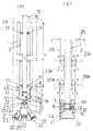
この既製杭1の外周に付着したドーナツ状の固化混合層29A、29Bが固化して、既製杭の環状突起として作用する。即ち、既製杭1に垂直荷重又は引抜力が固化混合層の上下面から上下の原地盤に対してせん断力の伝搬が図れ、鉛直支持力、引抜き力を増強する(図1(b)鎖線矢示図示)。
The doughnut-shaped solidified
(3) 固化混合層を形成しない層では、掘削土に固化剤を注入しないので、既製杭1の外周には、ほぐされ緩められた掘削土が、そのまま沈設される既製杭の外周により押圧された状態で蓄積される。即ち、固化混合層29Aと固化混合層29Bとの間の層(深度範囲)では、既製杭の外周側に放射状に押圧された掘削土層が形成される。
(3) In a layer that does not form a solidified mixed layer, no solidifying agent is injected into the excavated soil, so that the loosened and loosened excavated soil is pressed against the outer periphery of the
(4) 以上のように、所定の深さ位置で固化混合層29A、29Bを形成しながら、所定深さまで杭穴28を掘削したならば(図3(a)〜(c))、続いて根固め部を形成する。即ち、根固め部では掘削ヘッド18の下端部から高濃度のセメントミルクを注入しながら杭穴の下端部のみを撹拌混合して、必要により、掘削泥土を上方に押し上げ、根固め部内の掘削泥土をセメントミルクと置換等して、根固め層30を形成する(図3(d)(e))。根固め層30には、地盤強度以上の固化強度を有するセメントミルクを充填する。続いて、掘削ヘッド18を閉じて、既製杭1の中空部2を通って、地上25に引き上げる(図3(f))。
(4) As described above, if the
同時に、セメントミルクで満たされた(ソイルセメント状で存在する)杭穴28の根固め部内に、既製杭1の先端部を沈設して、既製杭1の下面が根固め部の底から所定の長さだけ空ける。以上のようにして、既製杭1の埋設が完了し、セメントミルクが固化発現後に、基礎杭構造33を形成する(図1(b))。
At the same time, the tip of the ready-made
この場合、根固め部の強化のためには、掘削ヘッド18の本体部あるいは上部に揚土及び撹拌を目的とするスパイラルを設けた掘削ロッドを使用することもできる(図示していない)。根固め部からできるだけ掘削土を排除し、あるいは、十分にセメントミルクと掘削土を撹拌混合して、良質の根固め層30を形成するためである。
In this case, in order to strengthen the root consolidation part, a drilling rod provided with a spiral for the purpose of earthing and stirring on the main body part or upper part of the
(5) 本発明の中掘り工法で使用する既製杭1は、根固め部において形成されたセメントミルクからなる根固め層30内で、根固め層30と一体となり、高い鉛直支持力及び引抜き力を発揮するために、付着面積の大きい突起(あるいは、節、らせん翼)付き既製杭1が望ましい。特に、既製杭1を沈設する際の押し入れ抵抗が少なく容易に押し入れでき、かつ付着表面積の大きくする為に、突起付き円筒形の鋼管本体6を基体とする先端金具13を、既製杭1の先端3に装着して構成することが望ましい。
(5) The ready-made
この中掘工法を採用する場合、使用する既製杭1の下端部に形成した、あるいは先端金具13に形成した大径の突起、例えば、比較的貫入抵抗の小さい構造で、かつ大径のらせん翼等を形成して、更に、高い支持力を有する基礎杭を構築することもできる。
In the case of adopting this digging method, a large-diameter protrusion formed on the lower end portion of the ready-made
また、この先端金具13は、突起で付着面積を大きく取る為に、円筒形の鋼管本体6を既製杭1の外径より大きくせず、押し込み抵抗を小さくする為に突起外径は上部に装着する既製杭1の外径と同等又は外径以下とし、突起の個数は、必要とされる根固め層30との必要な付着面積に合致させた枚数にすることが、所要支持力のバランスの点から適当である。更に、既製杭1を沈設する際に、先端金具13の突起面への土泥が付着することを防ぎ、根固め層30内での付着を高める必要から、突起部の外径を既製杭1の外径より若干大きくして付着面積を増加したり、突起の上下面にテーパー状の傾斜を付けることが望ましい。
In addition, the tip metal fitting 13 is not attached to the cylindrical
また、突起面への土泥の付着を防止する処理をすることにより、根固め層30が固化後の初期沈下を防止できる。
Moreover, the initial settlement after the
また、耐力を大きくするためには、先端金具13の突起の表面積は大きくすることが必要であるが、荷重時のせん断力伝搬の有効性および施工実務面では、その突起外径は逆に小さいことが必要である。従って、突起の基部に位置する鋼管本体6の外径は出来る限り小径とし、突起の外径は、既製杭を沈設する際に、貫入抵抗ができるだけ生じないように、上部に連結する既製杭1の外径と略同程度の寸法で余り大きくない寸法とすることが望ましい。即ち、支持力に関与する突起面から生じるせん断力の伝搬を考慮した時は、少なくとも突起部の外側面(下面又は上面)に所要寸法形状で、地盤強度よりの高固化強度のソイルセメント層が形成されていることが必須であるからである。
Further, in order to increase the proof stress, it is necessary to increase the surface area of the protrusion of the
また、先端金具13の各部表面と根固め部の根固め層(ソイルセメント層)30との付着強度の確保のために、先端金具13の突起部の表面積を広くするよう設計しているが、更に、施工時において、突起部表面に土泥が付着して両者の付着強度が低下することを防止することが必要である。特に、中掘工法では、先掘工法のようにソイルセメントが充填された杭穴内に既製杭1を沈設する場合と異なり、杭穴28を掘削してソイルセメントを形成している高さ位置(掘削ヘッド18の位置)の直上に既製杭1の先端3が位置しているので先端金具13と根固め層30との付着には配慮が必要である。従って、突起部の上下面は水平ではなく傾斜面であることが望ましいので節形状にしたり、あるいは沈設時に土泥が突起の上側面に巻き込まないように上部の杭外径より若干大きめ(外径大)の突起とするなど突起先端部の形状・寸法の工夫により支持力の確実かつ安定な発現が可能となる。
In addition, in order to ensure the adhesion strength between the surface of each part of the
(6) また、本発明の中掘工法で使用する掘削ロッド15は、開いた際に既製杭1の外径の1.4〜1.5倍の外径で杭穴掘削でき、かつ縮径して既製杭1の中空部2を通過できるように、その内径以下の外径として閉じることができる掘削ヘッド18を使用する。即ち、掘削ヘッド18は、縮径時と拡径時の比の大きい構造を必要とする。例えば、ロッド本体16に接続できるヘッド本体19の両側に、先端に掘削刃22を有する掘削腕21を揺動自在に取り付けて構成する(図1(a))。従って、この掘削ヘッド18を使用すれば、既製杭1の先端金具の突起(あるいは、既製杭の下端部外周に形成した突起)の外径が既製杭の軸部の外径より大径となった場合であっても、貫入時の抵抗を考慮した形状(例えば、らせん翼等)であれば、既製杭1を杭穴28内に容易に貫入埋設できる。
(6) Moreover, the
また、大きい拡径寸法が比較的容易に実現できる揺動式の掘削腕を利用した掘削ヘッドを使用した従来の中掘工法では、杭穴28の軸部での小径掘削(既製杭の外径+2cm程度)、杭穴28の拡底根固め部での大径掘削(既製杭の外径の約1.2倍程度)、掘削ヘッド18の引抜き時の縮径時(既製杭の内径以下)の3通りの制御ステップが必要であるが、本工法では、大径掘削・撹拌時と掘削ヘッド18の引抜きの2通りの制御ステップに減じているので、掘削ヘッド18の構造を簡素化でき、剛性強度の増強が可能となる。従って、大径掘削の制御が確実で安定化し信頼性が向上すると共に、補修や維持管理面でも安定化し経済的となる。
In addition, in the conventional medium digging method using the excavation head using a rocking excavation arm that can realize a large diameter expansion relatively easily, small-diameter excavation at the shaft portion of the pile hole 28 (the outer diameter of the ready-made pile). + 2cm), large-diameter excavation at the bottom-solidified portion of the pile hole 28 (about 1.2 times the outer diameter of the ready-made pile), when the diameter of the
尚、この工法で使用する掘削ヘッド18は、従来に比して、少なくとも既製杭1の外径の1.4〜1.5倍の掘削径を必要とするので、掘削手段の制御ステップを2つとすることにより、掘削腕21を有する構造で、剛性強度の高い構造の掘削ヘッド18を用いることにより実現できた。
The
また、掘削ロッド15のロッド本体16には、従来の中掘用ロッドのように排土を主目的としたスパイラルを省略することができる。杭穴28の芯及び既製杭1の中空部2の芯と掘削ロッド15の芯を合わせる為のスタビライザーの機能及び掘削ロッド15周辺の掘削土を撹拌する機能を有する部材を突設することが望ましい(図1(a))。
Further, the rod
(7) 本工法では、土質によっては、掘削径の大小を調節して(既製杭1の外径に対して、掘削ヘッド18の掘削径の比率を増減することで調節する)、既製杭1を速く沈設することができ、既製杭1の沈設速度を制御できるが、地盤の掘削及び粉砕性をより向上させるためには、大径掘削に適した掘削ヘッドが必要である。
(7) In this method, depending on the soil, the size of the excavation diameter is adjusted (adjusted by increasing / decreasing the ratio of the excavation diameter of the
例えば、筒状のヘッド本体19に外筒41を昇降可能に取り付け、ヘッド本体19の上端部に上部腕42の上端、外筒41の下端部に下部腕43の下端を夫々ピンで連結し、上部腕42の下端と下部腕43の上端とをピンで連結して、掘削ヘッド18を構成することもできる(図5)。この場合、上部腕42、下部腕43から掘削腕21を構成し、外筒41の下端に掘削刃20、20、上部腕43の下面側に掘削刃22、22が形成してある。
For example, the
この掘削ヘッドでは、外筒41とヘッド本体19とを相対的に上下動させ、掘削腕21の上部腕42と下部腕43とが重なるように(水平に近付くように)掘削径を拡大でき、駆動範囲が長く取れるので、通常の掘削ヘッドに比べて、縮径時(掘削腕21の上部腕42と下部腕43とが縦方向に配置された状態)即ち既製杭の外径に比べた比率が大きい掘削が可能であり、掘削刃も多段に形成できるので、粉砕性能も制御できる。従って、この掘削ヘッド18では、既製杭との杭径比で2倍以上の大径掘削・撹拌も可能となり、更に大きな支持力を発揮することが可能となる。
In this excavation head, the
また、掘削ヘッド18に、上下方向に複数のストッパーを設けることもでき(図示していない)、この場合には、異なる掘削径に容易に対応できる。よって、この掘削ヘッド18を使用することにより、掘削機(掘削ロッド15のロッド本体16)に一つの掘削ヘッド18を装着したまま、掘削位置を代えて異なる径の杭穴を形成する場合に、ストッパーの調節だけで、連続掘削が可能となる。また、1つの杭穴で、深さ方向で径が異なる軸部を有する杭穴を形成する場合にも、ストッパーの調節だけで、容易に掘削径の変更ができ、異なる径の固化混合層を有する基礎杭の構築も容易となる。
Further, the
(8) 以上のように、この発明では、既製杭1の外径の1.4〜1.5倍程度に掘削して、所定の地盤では固化混合層を形成できるので、この高濃度のソイルセメントからなる固化混合層が、既製杭1の外周に形成される環状突起としても作用する。例えば、外径800mmの既製杭の場合、外径1120〜1200mm程度の固化混合層が形成され、即ち、既製杭の外周に、突起高さ(水平方向の突出距離)160〜200mmの環状突起を形成できる。
(8) As described above, according to the present invention, this high-concentration soil can be excavated to about 1.4 to 1.5 times the outer diameter of the ready-made
この場合、既製杭1と固化混合層29A、29Bとは一体に作用するので、既製杭の外表面積を増加させて地盤との付着を増すと共に、既製杭1に鉛直荷重又は引抜力が作用した場合、固化混合層29A、29Bの上下面が応力伝搬面として作用し、当該上下面から軟弱地盤の上下に位置する地盤へ、せん断力が有効に伝搬して支持力を増強できる(図1(b))。
In this case, since the ready-made
このように、地盤を緩めたことにより既製杭の杭周部の摩擦力は低下するが、
低下した既製杭の杭周部の摩擦力を、固化混合層等を適宜形成することにより、復元、補強することができ、更に、固化混合層29A、29Bと既製杭1の外面との付着を充分に高めるように施工すれば、従来の既製杭1の軸部で発揮される支持力の約2倍程度の支持力を得られる。
In this way, by loosening the ground, the frictional force of the pile periphery of the ready-made pile is reduced,
The reduced friction force of the pile periphery of the ready-made pile can be restored and reinforced by appropriately forming a solidified mixed layer or the like, and further the adhesion between the solidified
また、既製杭の表面積が実質的に広くなり、既製杭の応力伝搬面積が広くなるので、周辺の弱い原地盤への伝搬荷重応力度(面積当たりの応力)を減少・緩和させ、基礎杭の耐荷重を増加させる。 In addition, since the surface area of the ready-made piles is substantially increased and the stress propagation area of the ready-made piles is increased, the degree of propagation load stress (stress per area) to the surrounding weak raw ground is reduced and relaxed. Increase load capacity.
また、指定した地層の高さ位置で、その面積を広く掘削・撹拌し、固化混合層29A、29Bを形成した直後で固まる前に、順次、既製杭1を押し込むことにより、既製杭1の押し込み抵抗(貫入抵抗)が少なくなり、既製杭を容易に沈設できる。
In addition, the
また、従来の中掘工法のように、掘削ロッドにスパイラル形状のような掘削土排出機構が不要となり、総排土量を低減できる。即ち、掘削径を従来より大幅に大径(例えば、既製杭の杭径に対して1.4倍以上)で地盤をほぐし緩めながら掘削し、既製杭を沈設すると、既製杭の外側面(外周面)で、ほぐした掘削土を略放射状に周辺の地盤に押し圧をかけながら既製杭を沈設し、基礎杭を構築するので、従来のように、掘削ロッドに排土機構を設けなくても既製杭の沈設ができる。 Moreover, unlike the conventional medium digging method, the excavation rod does not require a drilling soil discharge mechanism like a spiral shape, and the total amount of soil discharged can be reduced. That is, when the excavation diameter is significantly larger than before (for example, 1.4 times or more of the pile diameter of ready-made piles) and the ground is loosened and loosened, and the ready-made piles are laid down, ), The ready-made piles are laid down and the foundation piles are constructed while pressing the loosened excavated soil almost radially on the surrounding ground, so there is no need to provide a soil removal mechanism on the excavating rod as in the past. Ready-made piles can be laid.
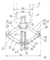
(9) 先掘工法により拡底根固め部35を有する杭穴を掘削し、地盤強度より高い固化強度のソイルセメントを充填した拡底根固め部35内に、下部軸部36を細径にし、下部軸部36を含む下端部に環状突起37、37を形成した既製杭1を埋設して、基礎杭構造38を形成した場合、その環状突起37、37の表面からせん断力が充分に伝搬できるように築造すれば(図6)、従来の円筒状の既製杭で発揮する支持力に比較して、約2倍の支持力が得られることが確認されている。本発明の基礎杭構造33では、先端金具13を固着させた既製杭1又は環状突起37を形成した既製杭1を上記のような手順で埋設するので(図2(a)(b)、図3)、従来の先掘工法によるこの基礎杭構造38と同等の高い支持力を発現させることが可能である(図6)。
(9) A pile hole having an expanded
従って、本発明では、中掘工法で、掘削径を既製杭の外径より大径(例えば、既製杭の外径の1.4倍以上)にすることにより、全体とし排土量を軽減できると共に、高い支持力が実現できる。 Therefore, in the present invention, the amount of soil removal can be reduced as a whole by making the excavation diameter larger than the outer diameter of the ready-made pile (for example, 1.4 times or more the outer diameter of the ready-made pile) by the medium excavation method. At the same time, a high supporting force can be realized.
次ぎに、この発明の具体的な実施形態を実施例に基づいて説明する。 Next, specific embodiments of the present invention will be described based on examples.
[1]既製杭1
[1] Ready-made
既製杭1として、下記形状・大きさの円筒形コンクリート杭を採用する。尚、必要耐力が大きい場合には、鋼管被覆コンクリート杭(SC杭)等を選択することもできる(図1(a)、図2(b))。
杭外径 D01=800mm
杭肉厚 t01=110mm
杭内径 D02=580mm
杭長 L01=19m
As the ready-made
Pile outer diameter D 01 = 800mm
Pile thickness t 01 = 110mm
Pile inside diameter D 02 = 580mm
Pile length L 01 = 19m
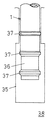
[2]先端金具13
[2]
外径D11、内径D12、全長L11の鋼管本体(厚さt11)6の上端部に、外径D13の大径部7を形成し、大径部7を既製杭1との連結部とする。大径部7は、上面8を水平平面状とし、下面9を徐々に小径とした部分円錐状の傾斜斜面を形成してある。連結部の外径、即ち、大径部7の外径D13は、接続するべき既製杭1の外径(D01下端部の外径)と略同一としてある。大径部7の幅(高さ)はL13で形成されている。
Outer diameter D 11, the inner diameter D 12, the upper end portion of the steel pipe pile body (
鋼管本体6の下端部外側面に、外径D13の円盤状(ドーナツ状)の環状突起10を突設する。環状突起10の上面11は、水平面状に形成し、下面12は部分円錐状の傾斜斜面を形成し、傾斜斜面の下端は鋼管本体6の下端に至っている。環状突起10の幅(高さ)はL13で形成されている(図2(b))。
A disc-shaped (doughnut-shaped)
以上のようにして、先端金具13を構成する(図2(b)、図1(a))。また大径部7と環状突起10との間隔はL12で形成され、突起部長さL14(=(D13−D11)÷2)とすると、支持面よりのせん断力の伝搬が障害なく作用するために、少なくとも
L12>L14×tanθ≒L14×tan30°=L14×√3
を満たすように形成されている。
As described above, the end fitting 13 is formed (FIGS. 2B and 1A). The distance between the
It is formed to satisfy.
尚、寸法は、下記のように形成する。
・鋼管本体1 外径D11=610mm
・鋼管本体1 内径D12=572mm
・鋼管本体1 長さL11=749mm
・大径部7の幅L13=119mm
・大径部7と環状突起10との間隔L12=430mm
The dimensions are formed as follows.
-
-
-
・ Width L 13 of the
-Distance L 12 = 430 mm between the
また、前記実施例では、鋼管本体6の内径D12は上部に連結する既製杭1の内径D02と同一とし、鋼管本体6の厚さt11を15〜40mm程度としているので、環状突起10の鋼材の節形状の外径D13を上部の既製杭1の外径D01以上に設定でき、突起面積(ソイルセメントとの付着面積)が大きく取れる。従って、形成する環状突起10の数を1個増加するだけで、既製杭1を外径で1ランク上の既製杭1で発揮する支持力と同等の支持力を得られる。
In the above embodiment, the inner diameter D 12 of the
[3]掘削ロッド15
[3]
中空のロッド本体16の先端部に掘削ヘッド18を装着して、掘削ロッド15を構成する。掘削ヘッド18は、ロッド本体16に接続できるヘッド本体19の両側に、掘削腕21、21の上端部を揺動自在に取り付けて構成する(図1(a))。ヘッド本体19は、中間部から下端部に向けて先細となるような扁平部を形成し、扁平部の先端に掘削刃20、20を突設してある。
An
掘削腕21は、上端部が回転軸24でヘッド本体19に取付られ、中間部は下方に向けて、ヘッド本体19の扁平部に沿うように、ヘッド本体19に近付くように屈曲し、掘削刃22、22を形成した下端部は下方に向けて、掘削刃22、22と共に外側に向けて開くように屈曲してある。このような形状とすることにより、掘削腕21、21は、回転抵抗が小さくなり、揺動し易くかつ掘削ヘッド18全体がコンパクトとなり、既製杭の中空部を挿通することが容易となるので、大径掘削が容易となる。
The
ヘッド本体19には、杭穴28の掘削径に対応して掘削腕21、21が揺動する範囲を制限するストッパー23、23が取り付けてある。
The head main body 19 is provided with
また、ロッド本体16には、排土用のスパイラルを省略して、所定高さ(例えば5m)毎に、水平板17、17を直径対称に取り付けてある。水平板17、17は、掘削ロッド15の軸と、杭穴28の軸又は既製杭1の軸とを合わせる(センタリング)する為のスタビライザーの機能、掘削土の撹拌の機能等を合わせ持つ。
Further, the rod
この掘削ヘッド18では、作動態様は、杭穴28の掘削時(杭穴軸部掘削時、固化混合層を形成する掘削・撹拌時、根固め部掘削・撹拌時)及び既製杭1の中空部2を通過する時の2通りのステップ方式に簡素化してある。掘削腕21を揺動させて、既製杭1の外径の1.5倍(1200mm)程度の外径で、掘削ロッド15に排土機構が無くても、確実かつ安定な掘削・撹拌を実現した。
In this
[4]中掘工法の説明 [4] Explanation of digging method
(1) 既製杭1を埋設予定の地盤(主要部分は砂質土)は、地上25から、6.5m〜7.5mの厚さ1m分、13.5m〜14.5mの厚さ1m分、に設計上指定された2箇所の(例えば比較的弱いN値5程度)地層26A、26Bが存在している(図1(b)、図3)。
(1) The ground (the main part is sandy soil) where the ready-made
(2) 先端金具13の大径部7の上面8を、既製杭1の先端3(下端板の下面)に当て、大径部7と下端板とをボルトや溶接等で一体に固定して、先端金具13付きの既製杭1を構成する(図2(b)、図1(a))。
(2) The
(3) 所定の掘削位置で、掘削ロッド15を、先端金具12付きの既製杭1の中空部2、先端金具13の中空部6aを挿通して、先端金具13の先端14から掘削ヘッド18を突出させる。
この状態で、既製杭1及び掘削ロッド15を鉛直に支持して、掘削ロッド15を回転させれば、掘削腕21がストッパー23で規制されるまで揺動し、その揺動角度を保ったまま、掘削腕の掘削刃22、22、ヘッド本体19の掘削刃20、20で、杭穴28を掘削できる。先端金具13の先端14から突出した掘削ヘッド18で、既製杭1の外径より大径の杭穴28の軸部を掘削する。掘削しながら掘削ロッド15を下降すると共に引き続き、既製杭1を下降させる(図3(a))。
(3) At a predetermined excavation position, the
In this state, if the ready-made
(4) 地上から6.0m程度掘削した所で、掘削土中に、ヘッド本体18からセメントミルク(固化強度20N/mm2程度)を注入し、掘削土と撹拌混合しながら約2mの間、掘削土とセメントミルクとを撹拌混合しながら掘削し、押し固めて、既製杭1の周囲にソイルセメント層29Aを形成する。ソイルセメント層(固化混合層)の形成は、設計上で指定された位置で行い、その地層26Aを含む上下高さを形成の対象とする。セメントミルクを注入するする際に、掘削ヘッド18を上下に昇降させれば、良く撹拌され、均質なソイルセメント層ができる。尚、ソイルセメント層(固化混合層)29Aは、固化強度0.5N/mm2程度とする。
(4) When excavated about 6.0 m from the ground, cement milk (solidification strength of about 20 N / mm 2 ) is injected into the excavated soil from the
また固化混合層を形成する高さ位置は、事前の標準貫入試験によるN値により概略把握できるので、そのN値が該当する高さ位置で固化混合層を形成することが望ましい。即ち、掘削中の掘削ロッド15を回転・昇降させるオーガーのモータの電流値を測定して、所定高さ範囲(例えば50cm)毎に積算して積算電流値を算出しておけば、標準貫入試験のN値と同一の深度で地盤強度の比較ができ、当該積算電流値を示すその高さ位置が該当する改良すべき地盤になるので、前記N値と併用することにより、正確な深度区間で固化混合層を形成できる。
Moreover, since the height position which forms a solidified mixed layer can be roughly grasped | ascertained by N value by a prior standard penetration test, it is desirable to form a solidified mixed layer in the height position where the N value corresponds. That is, if the current value of the motor of the auger that rotates and moves the excavating
(5) 形成したソイルセメント層29Aにも同様に、既製杭1を下降して、引き続き、掘削ロッド15を下降して、掘削ヘッド18で杭穴28を掘削しつつ既製杭1を下降する。
(5) Similarly, the ready-made
(6) 設計で指定した地層26Bに対応して、地上から13.0m〜15.0mの高さでも、同様に、ヘッド本体19からセメントミルクを吐出して、掘削土と撹拌混合して、ソイルセメント層(固化混合層)29Bを形成する(図3(b))。以降同様に、セメントミルクを使用せずに、杭穴28を掘削する(図3(c))。
このように、地盤改良等をしながら既製杭1を順次沈設するので、ソイルセメントの流出も阻止でき、固化混合層29A、29Bが確実に形成できる。
(6) Corresponding to the
Thus, since the ready-made
(7) 支持地盤(N値30)である所定深さ(約21m)まで、杭穴掘削したならば、杭穴底31から高さ2m程度の間で、セメントミルク(固化強度20N/mm2程度)を注入しながら掘削ヘッド18を回転し昇降して、掘削土とセメントミルクとを撹拌混合しながら根固め層30を形成する(図3(d)(e))。必要により、根固め部の底よりセメントミルクを吐出して掘削土を押し上げ、掘削土をセメントミルクに置換することもできる。
(7) If a pile hole is excavated to a predetermined depth (about 21 m), which is the supporting ground (N value 30), cement milk (solidification strength 20 N / mm 2 ) between the pile hole bottom 31 and about 2 m in height. The
(8) 周辺の地盤強度より高い固化強度20N/mm2程度の根固め層30を形成したならば、掘削ロッド15を逆転して掘削腕21、21を閉じて、掘削ロッド15の回転を一旦止めて掘削腕21、21をヘッド本体19に沿って垂れた状態にする(この状態で、掘削ヘッド18の最大外径は既製杭1の内径D02以下になっている)。続いて、掘削腕21、21が振れないように、掘削ロッド15をゆっくり回転して、根固め層30を撹拌しながら、掘削ヘッド18を掘削ロッド15と共に、先端金具13の中空部6a及び既製杭1の中空部2を挿通して(図3(f))、地上に引き上げる。
(8) If the
また、掘削ヘッド18のヘッド本体19で、掘削ロッド15が逆回転した際に掘削腕21、21が揺動する側に、ストッパーを取り付けておくこともでき(図示していない)、この場合には、逆回転させながら掘削ヘッド18を引き上げれば、既製杭1の中空部2の内壁を傷つけず、確実に掘削ヘッドを回収できる。
In addition, a stopper can be attached (not shown) to the side of the head main body 19 of the
(9) 続いて、あるいは掘削ロッド15の引き上げと並行して、既製杭1を下降して(図3(f))、先端金具13を根固め層30内に位置させ、先端金具13の先端(下端)14と杭穴底31とが既製杭1の軸部外径D01程度の距離L20(ここでは、約1mとした。図2(b))を空けた位置で、先端金具13付きの既製杭1を杭穴28内に保持する。
(9) Subsequently, or in parallel with the lifting of the excavating
ソイルセメント層29A、29B、根固め層30が固化発現後に、ソイルセメント層29A、29B及び根固め層30と既製杭1とが定着して一体に形成された基礎杭構造33を構築する(図1(b)、図2(b))。
After the
[5]試験結果 [5] Test results
本基礎杭構造33の築造に際し、セメントミルク注入量に相当する量の僅かな排土量で、掘削土をほとんど排出しないので、周辺地盤強度も締め固められており、載荷試験においても高い支持力の9300kN(最大荷重)が得られている。また、沈下特性のばらつきの改善が期待できる。
When constructing this foundation pile
また、従来の中掘工法であって、本工法の先端金具13を使用せず、本工法の根固め層内の先端金具13の外径600mmと同一径により、上端から下端まで形成したコンクリート製の既製杭を使用した従来の中掘工法と比較する。外径600mmの既製杭を使用し、根固め層内に既製杭の先端部を同様に定着させた場合、同一地盤で、最大荷重が約3100kNであった。 Moreover, it is a conventional medium digging method, which does not use the tip metal fitting 13 of this method, and is made of concrete formed from the upper end to the lower end with the same diameter as the outer diameter 600 mm of the tip metal fitting 13 in the rooting layer of this method. Compared with the conventional excavation method using existing piles. When a ready-made pile having an outer diameter of 600 mm was used and the tip of the ready-made pile was fixed in the rooting layer in the same manner, the maximum load was about 3100 kN on the same ground.
[6]他の実施例 [6] Other embodiments
(1) 前記実施例において、既製杭1を下降させるタイミングは、従来の中掘工法と同様に任意である。ただし、形成したソイルセメント層29A、29Bでは、当該層形成後に速やかに既製杭1を設置させることが望ましい。
(1) In the said Example, the timing which descends the ready-made
(2) また、前記実施例において、地層26A、26Bの2区間を改良し高濃度のソイルセメント層29A、29Bに置き換えた固化混合層を形成したが、N値の大小に関わらず他の区間にも高濃度のソイルセメント層を適宜形成し、軸部の支持力を増強させることが可能である(図示していない)。また、前記実施例では、特にN値の小さい区間のみ固化混合層を形成して、少ない処理で支持力増強効果の高い総合的な固化混合層を造成したが、施工地盤によっては、杭穴28の全深さに亘って固化強度0.5N/mm2以下で固化混合層を形成し、更に良くない地盤において高固化強度の例えば1.0N/mm2程度のソイルセメント層(固化混合層)を形成することも可能である。
(2) In the above embodiment, the two sections of the
ただし、新たに杭穴内に注入したセメントミルク等の分だけ、掘削土が杭穴より排出されるので、掘削土等の排出物を少なくするためには、セメントミルク等の注入を極力減らすことが望ましい。 However, since the excavated soil is discharged from the pile hole by the amount of cement milk newly injected into the pile hole, in order to reduce the discharge of excavated soil etc., the injection of cement milk etc. should be reduced as much as possible. desirable.
(3) また、前記実施例において、下端に先端金具13を固定した既製杭1を埋設したが、先端金具13を用いない他の既製杭1を使用することもできる。
(3) Moreover, in the said Example, although the ready-made
既製杭1として、下端部に上部軸部34より細くした下部軸部36を形成し、上部軸部34と下部軸部36の段差部分(境界部分)、段差部分の上方、段差部分の下方(下部軸部の下部)に環状突起37、37を夫々形成する。必要耐力が大きい場合には、連結杭として、下杭を上記既製杭として、上杭を鋼管被覆コンクリート杭(SC杭)等を選択することもできる(図2(a))。尚、上記における上部軸部34とは、軸部の下端部に形成した下部軸部36を除いた部分であって、中間部を含む軸部である。
As the ready-made
・杭外径(軸部) D01=700mm
・杭肉厚 t01=100mm
・杭内径 D02=500mm
・下部軸部の外径 D11=600mm
・環状突起37の外径D13=750mm
・杭穴の掘削径D21=1100mm
・杭の先端部が位置する地盤のN値=30
・ Pile outer diameter (shaft) D 01 = 700mm
· KuinikuAtsu t 01 = 100mm
・ Pile inner diameter D02 = 500mm
And lower shaft portion of the outer diameter D 11 = 600 mm
・ Outer diameter D 13 of
・ Drilling diameter of pile hole D 21 = 1100mm
-N value of the ground where the tip of the pile is located = 30
この場合、環状突起37、37の間隔L12及び下部軸部36からの環状突起37の長さL14は、前記実施例の大径部7と環状突起10との間隔L12と同様に設定する。また、環状突起37は、傾斜上面37a、傾斜下面37bを有し、傾斜下面37bは鋼管本体6の大径部の下面9や環状突起10の下面12と同様の機能を有するように設定する。傾斜上面37aも同様に形成されている。
In this case, the length L 14 of the
また、前記において、環状突起37の長さL14は、上部軸部34の外面より突設しない範囲で、環状突起37の傾斜上下面37a、37bをできるだけ広く確保できる構成とすることもでき、上記のようなL12との関係で設定する。
Further, in the above, the length L 14 of the
この先端金具13を使用せずに、環状突起37を形成した既製杭1を使用して、前記実施例と同様の施工により形成した基礎杭構造33の場合(図2(a))、同様の載荷試験を行った結果、最大荷重で7492kNの高い支持力が得られている。これを、根固め部内の環状突起37、環状突起10の径の相違を考慮した単位断面積あたりの支持力で比較すると、前記先端金具13を使用した基礎杭構造33の場合(図2(b))は618kN/m2、環状突起37付きの既製杭1の場合(図2(a))は565kN/m2で、同程度の支持力が期待できる。
In the case of the
また、この既製杭1は、前記実施例の先端金具13を固定した既製杭1と同様の工程で杭穴28内に埋設して、基礎杭構造33を構成する(図2(a))。尚、この場合、環状突起37の先端外周が最も外径が大きくなるので、土泥が付着し易いので、適当な方法で環状突起37、37を被覆すれば(図示していない)、根固め層30内で安定したより大きな支持力が発揮できる。
Moreover, this ready-made
この既製杭1で、環状突起37に代えて、環状突起を切断した環状でない突起、あるいは分散的に配置した突起から凸部を形成することもできる(図示していない)。また、この既製杭1で、傾斜上面37a、傾斜下面37bと同様な機能を有すれば、環状突起(凸部)37に代えて、環状凹部を形成することもできる(図示していない)。
In this ready-made
(4) また、前記実施例において、ロッド本体16に排土用のスパイラルを形成していない掘削ロッド15を使用することが排土を減らす点からは望ましいが、部分的に排土用のスパイラルをロッド本体16に形成し、あるいは、通常より外径が小さなスパイラルをロッド本体16の一部又は全部に形成した掘削ロッドを使用することもできる(図示していない)。これは、地盤強度が高い部分で掘削速度を速めることを優先する場合や、根固め部内からできるだけ掘削土を排除することを優先する場合等に有効である。
(4) In the above embodiment, it is desirable to use the
従って、前記発明の杭径より大径の杭穴掘削時に、掘削ロッドに多少の排土機構を設けて、排土量を制御することにより、施工速度と排土量(排土処理量)とを適宜組み合わせることができ、従来より経済的な基礎杭が施工できることが分かる。 Therefore, when excavating a hole with a diameter larger than the diameter of the pile according to the present invention, by providing some excavation mechanism to the excavation rod and controlling the amount of soil removed, the construction speed and the amount of soil removed (the amount of soil removed) It can be seen that the foundation pile can be constructed more economically than before.
1 既製杭
2 既製杭の中空部
3 既製杭の先端
6 鋼管本体
7 大径部
8 大径部の上面
9 大径部の下面
10 環状突起
11 環状突起の上面
12 環状突起の下面
13 先端金具
15 掘削ロッド
16 ロッド本体
17 水平板
18 掘削ヘッド
19 ヘッド本体
20 掘削刃
21 掘削腕
22 掘削刃
23 ストッパー
24 回転軸
25 地面
26A、26B 地層
28 杭穴
29A、29A 固化混合層
30 根固め層
31 杭穴底
33 基礎杭構造
34 上部軸部
36 下部軸部
37 環状突起
38 基礎杭構造(従来)
41 外筒
42 上部腕
43 下部腕
DESCRIPTION OF
41 outer cylinder 42 upper arm 43 lower arm
Claims (8)
Priority Applications (1)
| Application Number | Priority Date | Filing Date | Title |
|---|---|---|---|
| JP2009261392A JP5265500B2 (en) | 2002-09-30 | 2009-11-16 | Pile digging method, foundation pile structure |
Applications Claiming Priority (3)
| Application Number | Priority Date | Filing Date | Title |
|---|---|---|---|
| JP2002287127 | 2002-09-30 | ||
| JP2002287127 | 2002-09-30 | ||
| JP2009261392A JP5265500B2 (en) | 2002-09-30 | 2009-11-16 | Pile digging method, foundation pile structure |
Related Parent Applications (1)
| Application Number | Title | Priority Date | Filing Date |
|---|---|---|---|
| JP2004544915A Division JP4625896B2 (en) | 2002-09-30 | 2003-09-30 | Pile digging method |
Publications (2)
| Publication Number | Publication Date |
|---|---|
| JP2010031647A true JP2010031647A (en) | 2010-02-12 |
| JP5265500B2 JP5265500B2 (en) | 2013-08-14 |
Family
ID=32104947
Family Applications (4)
| Application Number | Title | Priority Date | Filing Date |
|---|---|---|---|
| JP2004544915A Expired - Lifetime JP4625896B2 (en) | 2002-09-30 | 2003-09-30 | Pile digging method |
| JP2009261392A Expired - Lifetime JP5265500B2 (en) | 2002-09-30 | 2009-11-16 | Pile digging method, foundation pile structure |
| JP2010120838A Expired - Lifetime JP5114529B2 (en) | 2002-09-30 | 2010-05-26 | Pile digging method |
| JP2012173109A Expired - Lifetime JP5520347B2 (en) | 2002-09-30 | 2012-08-03 | Pile digging method |
Family Applications Before (1)
| Application Number | Title | Priority Date | Filing Date |
|---|---|---|---|
| JP2004544915A Expired - Lifetime JP4625896B2 (en) | 2002-09-30 | 2003-09-30 | Pile digging method |
Family Applications After (2)
| Application Number | Title | Priority Date | Filing Date |
|---|---|---|---|
| JP2010120838A Expired - Lifetime JP5114529B2 (en) | 2002-09-30 | 2010-05-26 | Pile digging method |
| JP2012173109A Expired - Lifetime JP5520347B2 (en) | 2002-09-30 | 2012-08-03 | Pile digging method |
Country Status (5)
| Country | Link |
|---|---|
| JP (4) | JP4625896B2 (en) |
| KR (1) | KR101071122B1 (en) |
| CN (1) | CN100510276C (en) |
| AU (1) | AU2003266716A1 (en) |
| WO (1) | WO2004035942A1 (en) |
Cited By (1)
| Publication number | Priority date | Publication date | Assignee | Title |
|---|---|---|---|---|
| JP2014031622A (en) * | 2012-08-01 | 2014-02-20 | Mitani Sekisan Co Ltd | Method of burying precast pile |
Families Citing this family (22)
| Publication number | Priority date | Publication date | Assignee | Title |
|---|---|---|---|---|
| JP4625896B2 (en) * | 2002-09-30 | 2011-02-02 | 三谷セキサン株式会社 | Pile digging method |
| JP5674189B2 (en) * | 2010-04-30 | 2015-02-25 | 三谷セキサン株式会社 | Pile hole drilling head |
| CN101974905B (en) * | 2010-10-22 | 2013-04-24 | 上海中技桩业股份有限公司 | Pile-embedding method for hollow pile and auger drill for implementing same |
| CN102383429B (en) * | 2011-01-18 | 2016-08-10 | 上海城地建设股份有限公司 | Digging pile-sinking device in the middle of a kind of heavy caliber pile tube |
| CN102373708B (en) * | 2011-02-23 | 2016-03-02 | 上海城地建设股份有限公司 | Anchor method prestressed centrifugally pile tube and square sunk pile device and pile-sinking method thereof are drawn in middle pick |
| CN102383428B (en) * | 2011-02-23 | 2015-12-09 | 上海城地建设股份有限公司 | Middle pick reverse drawing method prestressed centrifugally pile tube pile-sinking device and pile-sinking method thereof |
| KR101224440B1 (en) | 2011-05-12 | 2013-01-21 | 시지엔지니어링(주) | Construction method of screw file |
| KR101416865B1 (en) * | 2011-05-12 | 2014-07-09 | 시지엔지니어링(주) | Construction method of screw file |
| CN102776884B (en) * | 2011-05-13 | 2016-01-20 | 上海城地建设股份有限公司 | In stir and rotate prestressed centrifugally pile tube pile-sinking device and pile-sinking method thereof |
| CN102776885A (en) * | 2011-05-13 | 2012-11-14 | 上海城地建设发展有限公司 | Middle-stirring inverse-pulling method based pre-stressed centrifugal tubular pile sinking device, and pile sinking method |
| CN102953382A (en) * | 2011-08-18 | 2013-03-06 | 上海城地建设发展有限公司 | Pile sinking device and pile sinking method for steel pipe pile by central stirring and reverse drawing |
| CN103628480A (en) * | 2012-08-27 | 2014-03-12 | 上海中技桩业股份有限公司 | Construction method and device for guide displacement pressure precast pile |
| CN105064351A (en) * | 2015-08-14 | 2015-11-18 | 云南大学 | Pile planting method |
| KR101834950B1 (en) * | 2017-05-15 | 2018-03-07 | (주)나다건설 | Micropile foundation structure and construction method of micropile foundation |
| KR101834948B1 (en) * | 2017-05-15 | 2018-04-19 | (주)나다건설 | Steel pipe micro-pile foundation system and construction method of micropile foundation using the same |
| JP6740276B2 (en) * | 2018-04-11 | 2020-08-12 | 株式会社トーヨーアサノ | Foundation pile and method of constructing foundation using the foundation pile |
| CN110835906B (en) * | 2019-11-27 | 2021-05-25 | 中国电建集团成都勘测设计研究院有限公司 | Method for determining bottom elevation of anti-impact rotary excavating pile of flood discharge outlet river bank |
| CN110886292B (en) * | 2019-11-29 | 2021-10-26 | 祝波 | Full-casing composite expanded-disk pile construction method and equipment |
| KR102347012B1 (en) | 2020-09-11 | 2022-01-04 | 주식회사 이지지오텍 | Under reaming auger apparatus and under reamed pile construction method using the same |
| KR20220035632A (en) | 2020-09-14 | 2022-03-22 | 주식회사 이지지오텍 | Under reaming auger apparatus and under reamed pile construction method using the same |
| CN113882376A (en) * | 2021-09-17 | 2022-01-04 | 湖南铁甲智能技术有限公司 | Pile sinking construction method and construction structure of prestressed pipe pile |
| KR102613542B1 (en) | 2021-10-22 | 2023-12-13 | 주식회사 이지지오텍 | Under reaming auger apparatus and under reamed pile construction method using the same |
Citations (6)
| Publication number | Priority date | Publication date | Assignee | Title |
|---|---|---|---|---|
| JPS63171438U (en) * | 1988-04-14 | 1988-11-08 | ||
| JPH0427011A (en) * | 1990-05-22 | 1992-01-30 | Asahi Chem Ind Co Ltd | Installation of tip-expanded pile by inner excavation |
| JP2002038469A (en) * | 2000-07-27 | 2002-02-06 | Nkk Corp | Execution method of precast pile |
| JP2002061178A (en) * | 2000-08-23 | 2002-02-28 | Mitani Sekisan Co Ltd | Method of burying existing pile with protrusion in pile installation by inner excavation and foundation pile structure |
| JP2002129557A (en) * | 2000-10-23 | 2002-05-09 | Tokyo Tokushu Kiso Kogyo:Kk | Pile burying method |
| WO2004035942A1 (en) * | 2002-09-30 | 2004-04-29 | Mitani Sekisan Co., Ltd. | Internal excavation method through pile, and foundation pile structure |
Family Cites Families (12)
| Publication number | Priority date | Publication date | Assignee | Title |
|---|---|---|---|---|
| JPS58185826A (en) * | 1982-04-23 | 1983-10-29 | Tenotsukusu:Kk | Construction of foundation pile |
| GB2132668B (en) * | 1982-12-22 | 1987-01-14 | Shekisan Kogyo Co Ltd | Concrete pile installing method |
| JPS6397711A (en) * | 1986-10-14 | 1988-04-28 | Nkk Corp | Soil cement composite pile |
| JPH02108724A (en) * | 1988-10-14 | 1990-04-20 | Takechi Koumushiyo:Kk | Enlarged-dia. hole drilling method and enlarged-dia. knot piling method |
| JPH0325121A (en) * | 1989-06-22 | 1991-02-01 | Nippon Concrete Ind Co Ltd | Sinking of pile in inner drilling pile method |
| JP2832481B2 (en) * | 1990-03-14 | 1998-12-09 | 三谷セキサン 株式会社 | Drilling rig for hole for concrete pile installation |
| JPH0626036A (en) * | 1992-07-03 | 1994-02-01 | Mitani Sekisan Co Ltd | Concrete pile installation method by inner excavation |
| JP3025121B2 (en) * | 1992-12-24 | 2000-03-27 | キヤノン株式会社 | Information processing method and apparatus |
| JP2000144727A (en) * | 1998-11-09 | 2000-05-26 | Geotop Corp | Construction method of footing pile |
| JP4671143B2 (en) * | 1999-04-13 | 2011-04-13 | 三谷セキサン株式会社 | Pile hole drilling head and pile hole drilling method |
| JP5024692B2 (en) * | 1999-12-27 | 2012-09-12 | 三谷セキサン株式会社 | Construction method of foundation pile, ready-made pile, pile hole drilling rod |
| JP4471510B2 (en) * | 2001-02-01 | 2010-06-02 | 住友金属工業株式会社 | Steel pipe soil cement pile, its construction method and construction equipment |
-
2003
- 2003-09-30 JP JP2004544915A patent/JP4625896B2/en not_active Expired - Lifetime
- 2003-09-30 AU AU2003266716A patent/AU2003266716A1/en not_active Abandoned
- 2003-09-30 CN CNB038231085A patent/CN100510276C/en not_active Expired - Lifetime
- 2003-09-30 WO PCT/JP2003/012522 patent/WO2004035942A1/en active Application Filing
- 2003-09-30 KR KR1020057004993A patent/KR101071122B1/en active IP Right Grant
-
2009
- 2009-11-16 JP JP2009261392A patent/JP5265500B2/en not_active Expired - Lifetime
-
2010
- 2010-05-26 JP JP2010120838A patent/JP5114529B2/en not_active Expired - Lifetime
-
2012
- 2012-08-03 JP JP2012173109A patent/JP5520347B2/en not_active Expired - Lifetime
Patent Citations (6)
| Publication number | Priority date | Publication date | Assignee | Title |
|---|---|---|---|---|
| JPS63171438U (en) * | 1988-04-14 | 1988-11-08 | ||
| JPH0427011A (en) * | 1990-05-22 | 1992-01-30 | Asahi Chem Ind Co Ltd | Installation of tip-expanded pile by inner excavation |
| JP2002038469A (en) * | 2000-07-27 | 2002-02-06 | Nkk Corp | Execution method of precast pile |
| JP2002061178A (en) * | 2000-08-23 | 2002-02-28 | Mitani Sekisan Co Ltd | Method of burying existing pile with protrusion in pile installation by inner excavation and foundation pile structure |
| JP2002129557A (en) * | 2000-10-23 | 2002-05-09 | Tokyo Tokushu Kiso Kogyo:Kk | Pile burying method |
| WO2004035942A1 (en) * | 2002-09-30 | 2004-04-29 | Mitani Sekisan Co., Ltd. | Internal excavation method through pile, and foundation pile structure |
Cited By (1)
| Publication number | Priority date | Publication date | Assignee | Title |
|---|---|---|---|---|
| JP2014031622A (en) * | 2012-08-01 | 2014-02-20 | Mitani Sekisan Co Ltd | Method of burying precast pile |
Also Published As
| Publication number | Publication date |
|---|---|
| JP5114529B2 (en) | 2013-01-09 |
| CN1685113A (en) | 2005-10-19 |
| JP2012207532A (en) | 2012-10-25 |
| JP5265500B2 (en) | 2013-08-14 |
| JP4625896B2 (en) | 2011-02-02 |
| AU2003266716A1 (en) | 2004-05-04 |
| JPWO2004035942A1 (en) | 2006-02-16 |
| WO2004035942A1 (en) | 2004-04-29 |
| JP2010209678A (en) | 2010-09-24 |
| KR101071122B1 (en) | 2011-10-07 |
| CN100510276C (en) | 2009-07-08 |
| KR20050059183A (en) | 2005-06-17 |
| JP5520347B2 (en) | 2014-06-11 |
Similar Documents
| Publication | Publication Date | Title |
|---|---|---|
| JP5520347B2 (en) | Pile digging method | |
| JP5045971B2 (en) | Ready-made piles and tip fittings | |
| JP2008057184A (en) | Method of constructing underground wall by using h-shaped pc pile | |
| JP4984308B2 (en) | Ready-made pile | |
| JP2004270440A (en) | Construction method for foundation pile, and prefabricated pile | |
| JP2003119775A (en) | Construction of foundation pile | |
| JP4724879B2 (en) | Foundation pile structure | |
| JP4485006B2 (en) | Construction method for underground structures | |
| JP4872561B2 (en) | Construction method of ready-made piles | |
| JP4724878B2 (en) | Foundation pile structure | |
| JP5024692B2 (en) | Construction method of foundation pile, ready-made pile, pile hole drilling rod | |
| JP4189550B2 (en) | Construction method of ready-made pile with spiral blade, casing for propulsion | |
| JP2004308411A (en) | Existing concrete pile foundation having large diameter and method for burying existing pile | |
| JP3514183B2 (en) | Embedded pile and its construction method | |
| JP2001271347A (en) | Drop method for ready-made pile | |
| JP4054903B2 (en) | Method of burying ready-made piles, foundation pile structure and ready-made piles | |
| JP2005240395A (en) | Rotary embedding method for pile | |
| JP4156313B2 (en) | Rotating method for ready-made piles | |
| JP2003147768A (en) | Ready-made pile burying method for reducing removal earth | |
| JPH11293669A (en) | Fixing construction method for pile | |
| JP2004027610A (en) | Burying method for prefabricated pile | |
| JP2004124540A (en) | Construction method for foundation pile | |
| JP2002054135A (en) | Composite structure | |
| JP2003096771A (en) | Precast soil-cement pile having composite blades | |
| JP2005098108A5 (en) |
Legal Events
| Date | Code | Title | Description |
|---|---|---|---|
| A621 | Written request for application examination |
Free format text: JAPANESE INTERMEDIATE CODE: A621 Effective date: 20091210 |
|
| A977 | Report on retrieval |
Free format text: JAPANESE INTERMEDIATE CODE: A971007 Effective date: 20120117 |
|
| A131 | Notification of reasons for refusal |
Free format text: JAPANESE INTERMEDIATE CODE: A131 Effective date: 20120221 |
|
| A521 | Request for written amendment filed |
Free format text: JAPANESE INTERMEDIATE CODE: A523 Effective date: 20120423 |
|
| A131 | Notification of reasons for refusal |
Free format text: JAPANESE INTERMEDIATE CODE: A131 Effective date: 20130205 |
|
| A521 | Request for written amendment filed |
Free format text: JAPANESE INTERMEDIATE CODE: A523 Effective date: 20130219 |
|
| TRDD | Decision of grant or rejection written | ||
| A01 | Written decision to grant a patent or to grant a registration (utility model) |
Free format text: JAPANESE INTERMEDIATE CODE: A01 Effective date: 20130312 |
|
| A61 | First payment of annual fees (during grant procedure) |
Free format text: JAPANESE INTERMEDIATE CODE: A61 Effective date: 20130501 |
|
| R150 | Certificate of patent or registration of utility model |
Ref document number: 5265500 Country of ref document: JP Free format text: JAPANESE INTERMEDIATE CODE: R150 Free format text: JAPANESE INTERMEDIATE CODE: R150 |
|
| R250 | Receipt of annual fees |
Free format text: JAPANESE INTERMEDIATE CODE: R250 |
|
| R250 | Receipt of annual fees |
Free format text: JAPANESE INTERMEDIATE CODE: R250 |
|
| R250 | Receipt of annual fees |
Free format text: JAPANESE INTERMEDIATE CODE: R250 |
|
| R250 | Receipt of annual fees |
Free format text: JAPANESE INTERMEDIATE CODE: R250 |
|
| R250 | Receipt of annual fees |
Free format text: JAPANESE INTERMEDIATE CODE: R250 |
|
| R250 | Receipt of annual fees |
Free format text: JAPANESE INTERMEDIATE CODE: R250 |
|
| R250 | Receipt of annual fees |
Free format text: JAPANESE INTERMEDIATE CODE: R250 |
|
| R250 | Receipt of annual fees |
Free format text: JAPANESE INTERMEDIATE CODE: R250 |
|
| EXPY | Cancellation because of completion of term |