JP2010029917A - Laser beam machining apparatus and laser beam machining method - Google Patents
Laser beam machining apparatus and laser beam machining method Download PDFInfo
- Publication number
- JP2010029917A JP2010029917A JP2008195640A JP2008195640A JP2010029917A JP 2010029917 A JP2010029917 A JP 2010029917A JP 2008195640 A JP2008195640 A JP 2008195640A JP 2008195640 A JP2008195640 A JP 2008195640A JP 2010029917 A JP2010029917 A JP 2010029917A
- Authority
- JP
- Japan
- Prior art keywords
- processing
- laser
- mark
- light
- workpiece
- Prior art date
- Legal status (The legal status is an assumption and is not a legal conclusion. Google has not performed a legal analysis and makes no representation as to the accuracy of the status listed.)
- Granted
Links
Images


Abstract
Description
本発明は、加工対象物にレーザ光を照射して、加工対象物の表面に微細なピット、連続した溝、または、反応跡を形成するレーザ加工装置およびレーザ加工方法に関する。 The present invention relates to a laser processing apparatus and a laser processing method for irradiating a processing target with laser light to form fine pits, continuous grooves, or reaction traces on the surface of the processing target.
従来から、加工対象物にレーザ光を照射して、加工対象物の表面に微細なピット、連続した溝、または、反応跡を形成するレーザ加工装置が知られている。また、レーザ光照射により加工された加工状態を監視する機能を備えたレーザ加工装置も知られている。例えば、特許文献1に示されたレーザ加工装置においては、レーザ加工のために加工対象物に照射したレーザ光の反射光の強度を検出し、その反射光強度と閾値との比較に基づいて、加工対象物の加工状態を検査している。
しかしながら、レーザ加工装置は、例えば、ピットを形成する場合においては、レーザ光の強度をパルス状に変化させて加工対象物に照射するため、反射光強度がハンチングする。また、レーザ加工を最適に行うために、レーザ光の強度を変化させることもある。このため、加工用レーザ光の反射光強度と閾値との比較に基づいて加工状態を検査しようとしても、閾値の設定が難しく、精度良い検査を行うことができない。 However, in the case of forming a pit, for example, the laser processing apparatus changes the intensity of the laser beam in a pulse shape and irradiates the object to be processed, so that the reflected light intensity hunts. Further, the intensity of the laser beam may be changed in order to optimally perform laser processing. For this reason, even if it is going to test | inspect a process state based on the comparison with the reflected light intensity | strength of the laser beam for process, and a threshold value, setting of a threshold value is difficult and an accurate test | inspection cannot be performed.
また、反射光強度に基づいて検出される加工状態の異常は、その原因が、加工対象物に付着している異物、あるいは、加工対象物に形成されている傷など加工対象物に起因するものが殆どである。そこで、レーザ加工の前に加工対象物の表面の異常(異物付着、傷等)を検査しておけば、レーザ加工時に上記検査を行う必要がなくなるが、今度は、製造工程の時間が増大してしまい生産効率が低下してしまう。また、新たに検査装置が必要となる。この結果、製造コストが増大してしまう。 In addition, abnormalities in the processing state detected based on the reflected light intensity are caused by a processing object such as a foreign object adhering to the processing object or a scratch formed on the processing object. Is most. Therefore, if the surface abnormality (foreign matter adhesion, scratch, etc.) of the workpiece is inspected before laser processing, it is not necessary to perform the above inspection at the time of laser processing, but this time the manufacturing process time increases. As a result, production efficiency decreases. In addition, a new inspection device is required. As a result, the manufacturing cost increases.
また、加工対象物の表面の異常は、異物付着や傷等によるものであるため、加工対象物の一部の加工エリアにのみ発生しているケースが多い。しかしながら、特許文献1のレーザ加工装置では、単に、加工状態を検査するだけで、その異常が発生している箇所を特定できないため、異常が検出された場合には、加工対象物をそのまま廃棄処分する必要が生じる。このため、レーザ加工後に加工対象物を複数に分割して製品を作製する場合には、正常にレーザ加工され製品とすることができる部分まで廃棄されてしまうことになる。このため、生産効率が悪い。
In addition, since the abnormality of the surface of the processing object is caused by foreign matter adhesion or scratches, it often occurs only in a part of the processing area of the processing object. However, in the laser processing apparatus of
本発明は、上記問題に対処するためになされたもので、生産効率を低下させることなく加工対象物を精度良く検査することを目的とする。 The present invention has been made in order to cope with the above-described problem, and an object thereof is to inspect a processing object with high accuracy without reducing production efficiency.
上記目的を達成するために、本発明の特徴は、加工対象物をセットするためのセット部と、前記セット部を回転させる回転手段と、第1レーザ光源と第2レーザ光源とを有し、両光源から出射されたレーザ光を前記加工対象物に向けて照射する加工ヘッドと、前記第1レーザ光源に駆動信号を出力して前記加工対象物の表面をレーザ加工可能な強度の加工用レーザ光を前記第1レーザ光源から出射させる第1レーザ駆動回路と、前記第2レーザ光源に駆動信号を出力して前記加工対象物の表面がレーザ加工されない強度の検査用レーザ光を前記第2レーザ光源から出射させる第2レーザ駆動回路と、前記第1レーザ光源から出射された加工用レーザ光の照射位置が、前記加工対象物の表面上を、前記セット部の回転により形成される照射移動軌跡に対して直交する方向に移動するように、前記セット部と前記加工ヘッドとの相対位置を変更する送り手段と、前記回転手段と前記送り手段との作動を制御しつつ、前記第1レーザ駆動回路を作動させて前記加工対象物の表面に加工用レーザ光を照射することにより、前記加工対象物の表面をレーザ加工する加工制御手段と、前記加工制御手段により前記加工対象物の表面をレーザ加工しているときに、前記第2レーザ駆動回路を作動させて前記加工対象物の表面に検査用レーザ光を照射する検査用レーザ光照射制御手段と、前記加工対象物の表面に照射した前記検査用レーザ光の反射光または透過光の強度を検出する光検出手段と、前記光検出手段により検出した反射光または透過光の強度に基づいて、前記加工対象物における異常を検出する異常検出手段とを備えたことにある。 In order to achieve the above object, a feature of the present invention includes a set part for setting a workpiece, a rotating means for rotating the set part, a first laser light source, and a second laser light source, A machining head that irradiates laser beams emitted from both light sources toward the workpiece, and a machining laser having a strength capable of laser machining the surface of the workpiece by outputting a drive signal to the first laser light source. A first laser driving circuit that emits light from the first laser light source; and a driving signal that is output to the second laser light source so that the surface of the object to be processed is not laser processed. A second laser drive circuit that emits light from a light source, and an irradiation position in which the irradiation position of the processing laser light emitted from the first laser light source is formed on the surface of the workpiece by the rotation of the set unit. The first laser is controlled while controlling the operation of the feed means for changing the relative position between the set portion and the processing head, the rotating means and the feed means so as to move in a direction perpendicular to the trace. By operating a drive circuit to irradiate the surface of the object to be processed with laser light for processing, processing control means for laser processing the surface of the object to be processed, and the surface of the object to be processed by the processing control means When laser processing is performed, the second laser driving circuit is operated to irradiate the surface of the workpiece with inspection laser light irradiation control means for irradiating the surface of the workpiece with inspection laser light. Based on the intensity of the reflected light or transmitted light detected by the light detecting means and the intensity of the reflected light or transmitted light of the inspection laser light, an abnormality in the workpiece is detected. In further comprising an abnormality detecting means for output.
本発明においては、第1レーザ光源と第2レーザ光源とを有する加工ヘッドを備えており、この加工ヘッドから、セット部にセット(固定)された加工対象物の表面にレーザ光を照射する。レーザ光の照射位置は、回転手段と送り手段との作動により移動する。回転手段は、セット部を回転させることにより、照射位置をセット部の回転軸周りに移動させる。送り手段は、セット部と加工ヘッドとの相対位置を変更してセット部の回転により形成される照射移動軌跡に対して直交する方向に照射位置を移動させる。この場合、セット部を固定しておいて加工ヘッドを移動させてもよいし、加工ヘッドを固定しておいてセット部を移動させてもよいし、両者を移動させるようにしてもよい。セット部としては、例えば、平板状の加工対象物を載置固定する円盤状テーブル、または、フィルム状の加工対象物を円筒外周面に捲いて固定し円筒軸周りに回転するドラム状固定治具などを用いることができる。送り手段の送り方向(セット部と加工ヘッドとの相対移動方向)は、円盤状テーブルの場合は、テーブル径方向となり、ドラム状固定治具の場合は、ドラム回転軸方向となる。 In this invention, the processing head which has a 1st laser light source and a 2nd laser light source is provided, and a laser beam is irradiated from this processing head to the surface of the process target set (fixed) to the set part. The irradiation position of the laser beam is moved by the operation of the rotating means and the feeding means. The rotation means moves the irradiation position around the rotation axis of the set unit by rotating the set unit. The feeding means changes the relative position between the setting unit and the machining head and moves the irradiation position in a direction orthogonal to the irradiation movement locus formed by the rotation of the setting unit. In this case, the processing head may be moved while the set portion is fixed, the set portion may be moved while the processing head is fixed, or both may be moved. As the set unit, for example, a disk-shaped table for mounting and fixing a plate-like workpiece or a drum-like fixture that rotates around a cylindrical axis by fixing a film-like workpiece on a cylindrical outer peripheral surface Etc. can be used. The feed direction of the feed means (the relative movement direction between the set portion and the machining head) is the table radial direction in the case of a disk-shaped table, and the drum rotation axis direction in the case of a drum-shaped fixture.
第1レーザ光源は、第1レーザ駆動回路から出力された駆動信号により作動して加工用レーザ光を出射して、加工対象物の表面をレーザ加工する。例えば、加工対象物の表面に微細なピット(断続的に形成される溝)、連続した溝、または、それらを形成するための反応跡(現像液等により変化する部分)を形成する。一方、第2レーザ光源は、第2レーザ駆動回路から出力された駆動信号により作動して検査用レーザ光を出射する。この検査用レーザ光は、加工対象物の表面に照射されても加工対象物が変化しない、つまり、レーザ加工されないように加工用レーザ光に比べて弱い強度に設定されている。 The first laser light source operates in accordance with the drive signal output from the first laser drive circuit, emits a processing laser beam, and laser-processes the surface of the processing object. For example, fine pits (intermittently formed grooves), continuous grooves, or reaction traces for forming them (parts that vary depending on the developer) are formed on the surface of the workpiece. On the other hand, the second laser light source operates in response to the drive signal output from the second laser drive circuit and emits inspection laser light. The inspection laser light is set to have a weaker intensity than the processing laser light so that the processing object does not change even when irradiated on the surface of the processing object, that is, laser processing is not performed.
加工制御手段は、回転手段と送り手段との作動を制御して照射位置を移動させつつ、第1レーザ駆動回路を作動させる。これにより、加工対象物の表面がレーザ加工される。このレーザ加工中においては、検査用レーザ光照射制御手段が第2レーザ駆動回路を作動させる。これにより、加工対象物の表面に検査用レーザ光が照射される。光検出手段は、加工対象物に照射された検査用レーザ光の反射光または透過光の強度を検出する。尚、検査用レーザ光の透過光を検出する場合には、セット部として光の透過率の大きな回転テーブルを用い、加工対象物と回転テーブルとを透過した透過光を回転テーブルの裏面側で受光して、その強度を検出すればよい。 The processing control means operates the first laser driving circuit while controlling the operation of the rotation means and the feeding means to move the irradiation position. Thereby, the surface of the workpiece is laser processed. During this laser processing, the inspection laser light irradiation control means operates the second laser drive circuit. Thereby, the surface of the workpiece is irradiated with the inspection laser beam. The light detection means detects the intensity of the reflected light or transmitted light of the inspection laser light irradiated on the workpiece. When detecting the transmitted light of the inspection laser light, a rotating table having a high light transmittance is used as the set portion, and the transmitted light transmitted through the workpiece and the rotating table is received on the back side of the rotating table. Then, what is necessary is just to detect the intensity | strength.
異常検出手段は、光検出手段により検出した反射光または透過光の強度に基づいて、加工対象物における異常を検出する。加工対象物の表面に異物が付着していたり傷が形成されていたりすると適正にレーザ加工できない。従って、こうした異物付着部や傷形成部を異常部とすることができる。加工対象物に異常部が存在すると、検査用レーザの反射光または透過光の強度が変化する。そこで、例えば、異常を判定するための閾値となる基準強度を予め設定しておき、検査用レーザの反射光または透過光の強度と、この基準強度とを比較することにより加工対象物の異常部を検出することができる。また、検査用レーザ光の反射光または透過光を受光する受光領域を複数に分割した光検出手段を設けて、各受光領域で検出した反射光または透過光の強度を使った演算式により得られる演算結果と、異常を判定するための基準値とを比較して、加工対象物の異常を検出するようにしてもよい。 The abnormality detection means detects an abnormality in the workpiece based on the intensity of the reflected light or transmitted light detected by the light detection means. If foreign matter adheres to the surface of the workpiece or scratches are formed, laser processing cannot be performed properly. Therefore, such a foreign substance adhesion part and a flaw formation part can be made into an abnormal part. If an abnormal part exists in the object to be processed, the intensity of reflected light or transmitted light of the inspection laser changes. Therefore, for example, a reference intensity serving as a threshold value for determining abnormality is set in advance, and the intensity of reflected or transmitted light of the inspection laser is compared with the reference intensity to determine an abnormal portion of the workpiece. Can be detected. In addition, a light detection means that divides a light receiving area for receiving reflected or transmitted light of the inspection laser light into a plurality of parts is provided, and obtained by an arithmetic expression using the intensity of reflected light or transmitted light detected in each light receiving area. The calculation result and a reference value for determining abnormality may be compared to detect abnormality of the workpiece.
検査用レーザ光は、加工対象物のレーザ加工に寄与しないため、その強度を異常検査に適した一定値に設定することができる。また、異常判定用の基準強度についても、検査用レーザ光の強度に応じた適正値に設定することができる。 Since the inspection laser light does not contribute to laser processing of the workpiece, the intensity can be set to a constant value suitable for abnormality inspection. Also, the reference intensity for abnormality determination can be set to an appropriate value according to the intensity of the inspection laser beam.
この結果、本発明によれば、加工対象物の精度の良い検査を行うことができる。しかも、加工用レーザ光の照射によるレーザ加工と同時に検査用レーザ光を照射してその反射光あるいは透過光の強度から異常を検出するため、製造工程におけるタクトタイムの増加を招くことがなく、生産効率を維持することができる。また、検査装置を別途設ける必要がないため、設備コスト、設置スペースも不要となり、製造コストを抑えることができる。 As a result, according to the present invention, it is possible to perform a highly accurate inspection of a workpiece. In addition, since the inspection laser light is irradiated simultaneously with the laser processing by the processing laser light irradiation and the abnormality is detected from the intensity of the reflected light or transmitted light, the production time is not increased and the production time is not increased. Efficiency can be maintained. Moreover, since it is not necessary to provide an inspection apparatus separately, an installation cost and installation space become unnecessary, and a manufacturing cost can be suppressed.
また、本発明の他の特徴は、前記加工ヘッドは、前記第2レーザ光源から出射される検査用レーザ光を、前記加工用レーザ光により前記加工対象物がレーザ加工されていない部分に照射することにある。この場合、前記加工ヘッドは、前記加工対象物の表面に照射した前記検査用レーザ光のスポット位置を、前記加工用レーザ光により前記加工対象物がレーザ加工される位置の加工方向前方直近位置に設定するとよい。 Another feature of the present invention is that the processing head irradiates a portion of the processing target that is not laser processed with the processing laser light, with the inspection laser light emitted from the second laser light source. There is. In this case, the processing head moves the spot position of the inspection laser light irradiated on the surface of the processing target to a position closest to the front in the processing direction of the position where the processing target is laser processed by the processing laser light. It is good to set.
本発明においては、第2レーザ光源から出射される検査用レーザ光が、加工用レーザ光により加工対象物がまだレーザ加工されていない部分に照射される。この場合、例えば、検査用レーザ光のスポット位置を、加工用レーザ光により加工対象物がレーザ加工される位置(加工用レーザ光のスポット位置)の加工方向前方直近位置に設定するとよい。従って、異常検出手段は、加工対象物の無垢の状態を検査することになる。レーザ加工状態の異常は、殆どが加工対象物の異常(異物付着や傷)に起因するものである。このため、レーザ加工状態を直接検査しなくても、加工対象物に形成された異常部を検出することで代用することができる。この場合、加工対象物に照射された検査用レーザ光の反射光あるいは透過光がレーザ加工跡の影響を受けないため、異常部を簡単にしかも精度良く検出することができる。 In the present invention, the inspection laser light emitted from the second laser light source is applied to the portion of the workpiece that has not yet been laser processed by the processing laser light. In this case, for example, the spot position of the inspection laser light may be set to the position closest to the front in the processing direction of the position where the processing target is laser processed by the processing laser light (spot position of the processing laser light). Therefore, the abnormality detection means inspects the innocent state of the workpiece. Abnormalities in the laser processing state are mostly caused by abnormalities (foreign matter adhesion or scratches) on the object to be processed. For this reason, even if it does not test | inspect a laser processing state directly, it can substitute by detecting the abnormal part formed in the process target object. In this case, since the reflected light or transmitted light of the inspection laser light irradiated on the object to be processed is not affected by the laser processing trace, the abnormal part can be detected easily and accurately.
尚、検査用レーザ光のスポット位置を、加工用レーザ光により加工対象物がレーザ加工される位置(加工用レーザ光のスポット位置)の加工方向前方直近位置に設定した場合には、例えば、加工用レーザ光と検査用レーザ光とを光軸をずらして共通の対物レンズから照射することができ、光学系部材を兼用することができる。 In addition, when the spot position of the inspection laser beam is set to the position closest to the front in the processing direction of the position where the workpiece is laser processed by the processing laser beam (spot position of the processing laser beam), for example, the processing The laser beam for inspection and the laser beam for inspection can be irradiated from a common objective lens while shifting the optical axis, and the optical system member can also be used.
また、本発明の他の特徴は、前記回転手段により回転する前記セット部の回転角度を検出する回転角度検出手段と、前記送り手段による変更される前記セット部と前記加工ヘッドとの相対位置を送り位置として検出する送り位置検出手段と、前記光検出手段により検出した前記反射光または透過光の強度の履歴を記憶する光履歴記憶手段と、前記異常検出手段により前記加工対象物における異常が検出されたときの、前記回転角度検出手段により検出される回転角度と、前記送り位置検出手段により検出される送り位置と、前記光履歴記憶手段により記憶した反射光または透過光の強度の履歴とを異常検出情報として取得する異常検出情報取得手段と、前記異常検出情報取得手段により取得した異常検出情報に基づいて、前記加工対象物の異常箇所を表す異常箇所情報を作成する異常箇所情報作成手段とを備えたことにある。 According to another aspect of the present invention, a rotation angle detection unit that detects a rotation angle of the set unit that is rotated by the rotation unit, and a relative position between the set unit that is changed by the feeding unit and the processing head are determined. An abnormality in the workpiece is detected by the feeding position detecting means for detecting the feeding position, a light history storing means for storing a history of the intensity of the reflected light or transmitted light detected by the light detecting means, and the abnormality detecting means. The rotation angle detected by the rotation angle detection means, the feed position detected by the feed position detection means, and the history of the intensity of the reflected light or transmitted light stored by the light history storage means. Based on the abnormality detection information acquired by the abnormality detection information acquisition means acquired as abnormality detection information and the abnormality detection information acquisition means, In that an abnormal point information creation means for creating anomaly information representing a location.
本発明においては、回転角度検出手段がセット部の回転角度を検出し、送り位置検出手段がセット部と加工ヘッドとの相対位置を送り位置として検出し、光履歴記憶手段が光検出手段により検出した反射光または透過光の強度の履歴を記憶する。そして、異常検出情報取得手段は、この3つの手段(回転角度検出手段、送り位置検出手段、光履歴記憶手段)を使って、異常検出手段により加工対象物における異常が検出されたときのセット部の回転角度と、送り位置と、反射光または透過光の強度の履歴とを異常検出情報として取得する。この異常検出情報は、異常が検出されたときの加工対象物に対する検査用レーザ光の照射位置と、異常が検出されるときまでの反射光または透過光の強度の履歴とを表す。従って、加工対象物における異常箇所(異常の発生している領域)を特定できるものとなる。 In the present invention, the rotation angle detection means detects the rotation angle of the set portion, the feed position detection means detects the relative position between the set portion and the machining head as the feed position, and the light history storage means detects by the light detection means. A history of the intensity of the reflected or transmitted light is stored. Then, the abnormality detection information acquisition means uses these three means (rotation angle detection means, feed position detection means, light history storage means), and a set unit when an abnormality in the workpiece is detected by the abnormality detection means The rotation angle, the feed position, and the history of the intensity of the reflected light or transmitted light are acquired as abnormality detection information. This abnormality detection information represents the irradiation position of the inspection laser beam on the object to be processed when the abnormality is detected, and the history of the intensity of the reflected light or transmitted light until the abnormality is detected. Accordingly, it is possible to identify an abnormal part (an area where an abnormality has occurred) in the workpiece.
そこで、異常箇所情報作成手段は、この異常検出情報に基づいて加工対象物の異常箇所を表す異常箇所情報を作成する。従って、本発明によれば、加工対象物における異常箇所を把握することができるため、レーザ加工終了後の工程において加工対象物を複数に分割して製品を作製する場合には、異常箇所を除いた部分を製品とすることができる。つまり、異常が検出されたからといって、そのまま加工対象物を廃棄処分してしまう必要はなく、正常部分を有効に利用することができる。この結果、生産効率が一層向上する。 Therefore, the abnormal part information creating means creates abnormal part information representing the abnormal part of the workpiece based on the abnormality detection information. Therefore, according to the present invention, since an abnormal part in the object to be processed can be grasped, when the product is manufactured by dividing the object to be processed into a plurality of parts in the process after the laser processing is finished, the abnormal part is excluded. The part can be a product. That is, it is not necessary to dispose of the processing object as it is because an abnormality is detected, and the normal part can be used effectively. As a result, production efficiency is further improved.
また、本発明の他の特徴は、前記異常検出手段は、前記検出した反射光または透過光の強度が、予め設定した異常を判定するための閾値となる基準強度を境界として正常値側から異常値側の範囲に入り、その後、予め設定した異常判定用基準時間以上経過した後に、正常値側の範囲に戻った時に異常検出信号を出力するものであり、前記異常検出情報取得手段は、前記異常検出信号が出力されたときの前記回転角度検出手段により検出される回転角度と前記送り位置検出手段により検出される送り位置とを異常検出点情報として取得するとともに、前記異常検出信号が出力される直前の前記光履歴記憶手段に記憶されている反射光または透過光の強度の履歴を取得するものであり、前記異常箇所情報作成手段は、前記光履歴記憶手段に記憶されている反射光または透過光の強度が前記異常値側の範囲に入っている連続時間に基づいて前記加工対象物の回転方向における異常範囲長を計算し、その異常範囲長と前記異常検出点情報とから前記異常箇所情報を作成することにある。 Another feature of the present invention is that the abnormality detecting means detects that the intensity of the detected reflected light or transmitted light is abnormal from the normal value side with a reference intensity as a threshold for determining a preset abnormality. After entering the value-side range, and after elapse of the preset abnormality determination reference time, the abnormality detection signal is output when returning to the normal value-side range. The rotation angle detected by the rotation angle detection means when the abnormality detection signal is output and the feed position detected by the feed position detection means are acquired as abnormality detection point information, and the abnormality detection signal is output. The intensity history of reflected light or transmitted light stored in the light history storage means immediately before the acquisition is acquired, and the abnormal location information creation means is stored in the light history storage means. The abnormal range length in the rotation direction of the workpiece is calculated based on the continuous time in which the intensity of reflected light or transmitted light is within the range on the abnormal value side, and the abnormal range length and the abnormal detection point information are calculated. The abnormal part information is created from the above.
本発明においては、検出した反射光または透過光の強度が、予め設定した異常を判定するための閾値となる基準強度を境界として正常値側から異常値側の範囲に入り、その後、予め設定した異常判定用基準時間以上経過した後に、正常値側の範囲に戻った時に異常検出手段が異常検出信号を出力する。異常判定用基準時間以上の時間経過を要件としているのは、検出した光強度が一時的なノイズにより変動して正常値側から外れ誤判定してしまうことを防止するためである。異常検出信号が出力された時点において検査用レーザ光が加工対象物を照射していた位置は、異常部の終了位置とみなすことができる。従って、異常検出信号が出力されたときの回転角度と送り位置とは、異常部の終了点を特定できる異常検出点情報となる。 In the present invention, the intensity of the detected reflected or transmitted light enters the range from the normal value side to the abnormal value side with a reference intensity serving as a threshold for determining a preset abnormality, and then set in advance. The abnormality detection means outputs an abnormality detection signal when it returns to the normal value range after elapse of the abnormality determination reference time. The requirement that time elapses more than the abnormality determination reference time is to prevent the detected light intensity from fluctuating due to temporary noise and deviating from the normal value side to make an erroneous determination. The position where the inspection laser beam is irradiating the object to be processed at the time when the abnormality detection signal is output can be regarded as the end position of the abnormal portion. Therefore, the rotation angle and the feed position when the abnormality detection signal is output become abnormality detection point information that can specify the end point of the abnormal part.
異常検出情報取得手段は、異常検出信号が出力されたとき、この異常検出点情報と、異常検出信号が出力される直前の光履歴記憶手段に記憶されている反射光または透過光の強度の履歴を取得する。光履歴記憶手段に記憶されている反射光または透過光の強度が異常値側に入っている連続時間(例えば、一定のサンプリング周期で光強度データを記憶する場合にはデータの数)がわかれば、加工対象物の回転方向における異常部の長さを計算することができる。例えば、連続時間に検査用レーザ光の照射位置の線速度を乗じればよい。そこで、異常箇所情報作成手段は、光履歴記憶手段に記憶されている反射光または透過光の強度が異常値側の範囲に入っている連続時間に基づいて加工対象物の回転方向における異常範囲長を計算し、その異常範囲長と異常検出点情報とから異常箇所情報を作成する。従って、本発明によれば、加工対象物における異常箇所情報の作成が容易であり、また、精度の高い異常箇所情報を得ることができる。 When the abnormality detection signal is output, the abnormality detection information acquisition unit records the abnormality detection point information and the history of the intensity of reflected light or transmitted light stored in the light history storage unit immediately before the abnormality detection signal is output. To get. If the continuous time during which the intensity of the reflected or transmitted light stored in the light history storage means is on the abnormal value side (for example, the number of data when storing light intensity data at a constant sampling period) is known The length of the abnormal part in the rotation direction of the workpiece can be calculated. For example, the continuous time may be multiplied by the linear velocity of the irradiation position of the inspection laser beam. Therefore, the abnormal part information creating unit is configured to detect the abnormal range length in the rotation direction of the workpiece based on the continuous time in which the intensity of the reflected light or transmitted light stored in the light history storage unit is within the range on the abnormal value side. , And abnormal part information is created from the abnormal range length and abnormality detection point information. Therefore, according to the present invention, it is easy to create abnormal part information on the workpiece, and it is possible to obtain abnormal part information with high accuracy.
また、本発明の他の特徴は、前記送り位置検出手段により検出される送り位置および前記回転角度検出手段により検出される回転角度に基づいて、前記加工用レーザ光の照射位置が前記加工対象物の外周部であって設定回転角度となるマーク形成目標位置となるように、前記送り手段と前記回転手段とを駆動制御するマーク位置移動制御手段と、前記第1レーザ駆動回路を作動させて、前記加工対象物のマーク形成目標位置に前記加工用レーザ光を照射し、前記加工対象物のマーク形成目標位置にマークを形成するマーク形成手段とを備えたことにある。 Another feature of the present invention is that the irradiation position of the processing laser light is determined based on the feed position detected by the feed position detection means and the rotation angle detected by the rotation angle detection means. The mark position movement control means for driving and controlling the feeding means and the rotation means, and the first laser drive circuit so as to be a mark formation target position having a set rotation angle at the outer peripheral portion of There is provided mark forming means for irradiating the mark forming target position of the processing object with the processing laser beam and forming a mark at the mark forming target position of the processing object.
本発明においては、加工対象物の表面にマークを形成することにより、マークを基準として異常箇所を把握できるようにしている。このマークは、マーク形成手段がマーク目標形成位置に加工用レーザ光を照射することにより形成される。マーク形成目標位置は、加工用レーザ光の照射位置が、加工対象物の外周部となる位置で、かつ、セット部の回転角度が設定回転角度となる位置である。マークの形成に際して、マーク位置移動制御手段は、送り位置検出手段により検出される送り位置と回転角度検出手段により検出される回転角度とに基づいて、送り手段と回転手段とを駆動制御して加工用レーザ光の照射位置をマーク形成目標位置に合わせる。その後、マーク形成手段が加工用レーザ光を照射して加工対象物にマークを形成する。 In the present invention, by forming a mark on the surface of the object to be processed, an abnormal location can be grasped based on the mark. This mark is formed when the mark forming means irradiates a processing laser beam to the mark target forming position. The mark formation target position is a position where the irradiation position of the processing laser beam is the outer peripheral portion of the processing object, and the rotation angle of the set portion is the set rotation angle. When forming the mark, the mark position movement control means drives and controls the feed means and the rotation means based on the feed position detected by the feed position detection means and the rotation angle detected by the rotation angle detection means. The laser beam irradiation position is adjusted to the mark formation target position. Thereafter, the mark forming means irradiates a processing laser beam to form a mark on the object to be processed.
従って、レーザ加工を使って異常箇所情報とマーク形成位置とを関連させることができる。このため、作業者は、このマークを基準として、どの位置にどの程度の大きさの異常部が存在するのかを知ることができる。また、レーザ加工時においてマークを形成することができるため、前もってマークが形成された加工対象物を用意する必要がなく、また、その加工対象物をセット部にセットするときにマークをセット部の所定位置に合わせる必要もなく、生産効率が向上する。 Therefore, the abnormal part information and the mark formation position can be related using laser processing. For this reason, the operator can know how much an abnormal portion exists at which position with reference to this mark. In addition, since a mark can be formed during laser processing, there is no need to prepare a workpiece on which a mark has been formed in advance, and when the workpiece is set on the set portion, the mark is placed on the set portion. There is no need to adjust to a predetermined position, and the production efficiency is improved.
本発明の他の特徴は、前記セット部は、同一形状の複数の加工対象物を前記セット部の回転軸を中心とした同一円周上に配置して固定する固定治具を備え、前記複数の加工対象物の前記セット部に対する固定位置を検出する固定位置検出手段と、前記固定位置検出手段により検出されたそれぞれの加工対象物の固定位置に基づき、前記異常箇所情報作成手段により作成された異常箇所情報をそれぞれの加工対象物における座標に基づいた異常箇所情報に変換する異常箇所情報変換手段とを備えたことにある。 Another feature of the present invention is that the set unit includes a fixing jig that fixes and arranges a plurality of workpieces having the same shape on the same circumference around the rotation axis of the set unit. Based on the fixed position detection means for detecting the fixed position of the processing object with respect to the set portion and the fixed position of each processing object detected by the fixed position detection means, It is provided with an abnormal part information converting means for converting abnormal part information into abnormal part information based on coordinates in each processing object.
本発明においては、固定治具を使って複数の加工対象物をセット部に同一円周上に配置してレーザ加工を行うため生産効率が高い。この場合、異常箇所情報作成手段により作成された異常箇所情報は、セット部におけるレーザ光照射位置を座標として表したものであるため、複数の加工対象物をセット部に配置して一度にレーザ加工を行うシステムにおいては、異常箇所情報を各加工対象物の座標に変換する必要がある。そこで、固定位置検出手段は、複数の加工対象物のセット部に対する固定位置を検出する。そして、異常箇所情報変換手段は、検出した加工対象物の固定位置に基づいて、異常箇所情報をそれぞれの加工対象物における座標に基づいた異常箇所情報に変換する。この結果、異常箇所情報をそれぞれの加工対象物に適正に使うことができる。 In the present invention, since a plurality of objects to be processed are arranged on the same circumference in the set portion using a fixing jig and laser processing is performed, the production efficiency is high. In this case, since the abnormal part information created by the abnormal part information creating means represents the laser beam irradiation position in the set unit as coordinates, a plurality of processing objects are arranged in the set unit and laser processing is performed at once. In the system which performs, it is necessary to convert abnormal part information into the coordinates of each processing object. Therefore, the fixed position detecting means detects fixed positions with respect to the set portions of the plurality of workpieces. Then, the abnormal part information converting means converts the abnormal part information into abnormal part information based on the coordinates of each processing object based on the detected fixed position of the processing object. As a result, the abnormal part information can be appropriately used for each processing object.
本発明の他の特徴は、前記各加工対象物の外周部であって各加工対象物の中心と前記セット部の回転中心とを結ぶ直線上の位置をマーク形成目標位置として演算するマーク目標位置演算手段と、前記加工用レーザ光の照射位置が1つの加工対象物のマーク形成目標位置となるように、前記送り手段と前記回転手段とを駆動制御するマーク位置移動制御手段と、前記第1レーザ駆動回路を作動させて、前記1つの加工対象物のマーク形成目標位置に前記加工用レーザ光を照射し、前記加工対象物のマーク形成目標位置にマークを形成するマーク形成手段と、前記マーク位置移動制御手段による前記加工用レーザ光の前記マーク形成目標位置への移動と、前記マーク形成手段による前記加工対象物のマーク形成目標位置への前記加工用レーザ光の照射とを、前記各加工対象物のそれぞれに対して行うように、前記マーク位置移動制御手段と前記マーク形成手段とに指示する繰り返し手段とを備えたことにある。 Another feature of the present invention is a mark target position for calculating a position on a straight line connecting the center of each processing object and the center of rotation of the set portion as a mark formation target position on the outer periphery of each processing object. A calculation means; mark position movement control means for drivingly controlling the feeding means and the rotation means so that the irradiation position of the processing laser beam is a mark formation target position of one processing object; Mark forming means for operating a laser driving circuit to irradiate the mark forming target position of the one object to be processed with the laser beam for processing to form a mark at the mark forming target position of the object to be processed, and the mark The movement of the processing laser light to the mark formation target position by the position movement control means, and the processing laser light to the mark formation target position of the workpiece by the mark formation means. Out of the so performed as to each of the workpiece is to have a repeating unit that instruct the said mark forming means and the mark position movement control means.
本発明においては、セット部に同一円周上に配置された複数の加工対象物のそれぞれに対して、そのマーク形成目標位置に加工用レーザ光を照射してマークを形成する。マークを形成するに際して、マーク目標位置演算手段は、各加工対象物の外周部であって各加工対象物の中心とセット部の回転中心とを結ぶ直線上の位置をマーク形成目標位置として演算する。そして、マーク位置移動制御手段が、送り手段と回転手段とを駆動制御して加工用レーザ光の照射位置を1つの加工対象物のマーク形成目標位置に合わせ、マーク形成手段が、第1レーザ駆動回路を作動させてマーク形成目標位置に加工用レーザ光を照射し、加工対象物にマークを形成する。そして、繰り返し手段が、マーク位置移動制御手段によるマーク形成目標位置への移動と、マーク形成手段による加工用レーザ光の照射とを、各加工対象物のそれぞれに対して行うように両手段に指示する。これにより、各加工対象物に対して、マークを適正位置に形成することができる。尚、各加工対象物の外周部であって各加工対象物の中心とセット部の回転中心とを結ぶ直線上の位置は、セット部の回転中心から近い箇所と遠い箇所との2箇所存在するが、いずれか一方をマーク形成目標位置とすればよい。 In the present invention, a mark is formed by irradiating each mark forming target position with a processing laser beam to each of a plurality of objects to be processed arranged on the same circumference in the set portion. When forming the mark, the mark target position calculation means calculates the position on the straight line connecting the center of each processing object and the rotation center of the set portion as the mark formation target position. . Then, the mark position movement control means drives and controls the feeding means and the rotation means so that the irradiation position of the processing laser light is matched with the mark formation target position of one processing object, and the mark formation means drives the first laser. The circuit is operated to irradiate a processing laser beam to the mark formation target position, thereby forming a mark on the object to be processed. Then, the repeating means instructs both means to perform movement to the mark formation target position by the mark position movement control means and irradiation of the processing laser beam by the mark forming means to each of the workpieces. To do. Thereby, a mark can be formed in an appropriate position with respect to each processing object. Incidentally, there are two positions on the outer periphery of each processing object and on the straight line connecting the center of each processing object and the rotation center of the set part, a place near and far from the rotation center of the set part. However, either one may be set as the mark formation target position.
また、本発明の他の特徴は、前記マーク形成手段は、前記異常検出手段により異常が検出された加工対象物に対してのみ前記マークを形成することにある。これによれば、異常が検出されなかった加工対象物にはマークを形成しないため、生産効率が一層向上する。また、作業者は、マークの有無により、加工対象物の異常部の有無を知ることができる。 Another feature of the present invention resides in that the mark forming unit forms the mark only on a workpiece whose abnormality is detected by the abnormality detecting unit. According to this, since a mark is not formed on the processing object in which no abnormality is detected, the production efficiency is further improved. Also, the operator can know the presence or absence of an abnormal part of the workpiece by the presence or absence of the mark.
また、本発明の他の特徴は、前記マーク形成手段は、前記送り手段により前記加工用レーザ光の照射位置を移動させながら前記第1レーザ駆動回路を作動させて前記加工用レーザ光を照射することにより、前記加工対象物の外周部に前記送り手段の送り方向に延びた直線状のマークを形成することにある。これによれば、マークの形成が容易であり、しかも、マークが直線状に形成されるため、マークの識別も容易となる。 Another feature of the present invention is that the mark forming means irradiates the processing laser light by operating the first laser driving circuit while moving the irradiation position of the processing laser light by the feeding means. Thus, a linear mark extending in the feeding direction of the feeding means is formed on the outer peripheral portion of the workpiece. According to this, the mark can be easily formed, and the mark can be easily identified because the mark is formed in a straight line.
更に、本発明の実施にあたっては、レーザ加工装置の発明に限定されることなく、レーザ加工方法の発明としても実施し得るものである。 Furthermore, in carrying out the present invention, the invention is not limited to the invention of the laser processing apparatus, but can also be implemented as an invention of a laser processing method.
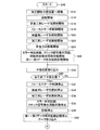
以下、本発明の一実施形態について図面を用いて説明する。図1は、第1実施形態に係るレーザ加工装置1の概略システム構成図である。このレーザ加工装置1は、加工対象物OBを固定支持する支持部材としてのテーブル21と、加工対象物OBに向けてレーザ光を照射して加工対象物OBをレーザ加工する加工ヘッド30とを備えている。加工対象物OBは、レーザ加工され、最終的には、例えば反射防止膜や偏光板等の機能性材料として使用される。テーブル21は、円盤状に形成されていて、スピンドルモータ22およびフィードモータ23によって駆動される。加工ヘッド30は、装置本体に固定されたヘッド支持フレーム(図示略)により固定されている。
Hereinafter, an embodiment of the present invention will be described with reference to the drawings. FIG. 1 is a schematic system configuration diagram of a
スピンドルモータ22は、その回転により、回転軸22bを介してテーブル21を回転駆動する。スピンドルモータ22内には、同モータ22すなわちテーブル21の回転を検出して、その回転を表す回転検出信号を出力するエンコーダ22aが組み込まれている。この回転検出信号は、テーブル21の回転位置が一つの基準回転位置に来るごとに発生されるインデックス信号と、所定の微少な回転角度ずつハイレベルとローレベルを繰り返すパルス列信号であって互いにπ/2だけ位相のずれたA相信号およびB相信号とからなる。
The
回転検出信号のうちインデックス信号は、回転角度検出回路51に供給され、パルス列信号は、スピンドルモータ制御回路53と回転角度検出回路51とに供給される。スピンドルモータ制御回路53は、コントローラ90からの回転速度指示により作動開始し、エンコーダ22aから出力されるパルス列信号(A相信号およびB相信号)の単位時間あたりのパルス数によりスピンドルモータ22の回転速度を計算し、計算した回転速度がコントローラ90によって指示された回転速度に等しくなるようにスピンドルモータ22の回転を制御する。
Of the rotation detection signals, the index signal is supplied to the rotation
回転角度検出回路51は、コントローラ90からの指示により作動を開始し、エンコーダ22aから出力されるパルス列信号のパルス数をカウントし、そのカウント値からテーブル21の回転角度を計算し、回転角度を表すデジタル信号を第2データ保存回路62とコントローラ90とに出力する。また、回転角度検出回路51は、エンコーダ22aからインデックス信号を入力したときにパルス数のカウント値をゼロクリアする。つまり、インデックス信号が入力した時点のテーブル21の回転角度を0°とする。
The rotation
フィードモータ23は、スクリューロッド24を回転させて、テーブル21を半径方向に駆動する。スクリューロッド24は、その一端にてフィードモータ23の回転軸に一体回転するように連結され、その他端に支持部材25に固着されたナット(図示しない)に螺合している。支持部材25は、スピンドルモータ22を固定支持するとともに、テーブル21の半径方向への移動のみが許容されている。従って、フィードモータ23が回転すると、スピンドルモータ22、テーブル21および支持部材25は、スクリューロッド24およびナットからなる送りネジ機構20によりテーブル21の径方向に変位する。テーブル21の移動方向は、テーブル21の回転中心の移動軌跡を表す直線が、加工ヘッド30の照射位置を通るように設定されている。
The
フィードモータ23内にも、フィードモータ23の回転を検出して、前記エンコーダ22aと同様な回転検出信号(インデックス信号及びA相信号およびB相信号からなるパルス列信号)を出力するエンコーダ23aが組み込まれている。エンコーダ23aから出力されるパルス列信号は、フィードモータ制御回路54と半径位置検出回路52とに出力される。半径位置検出回路52は、エンコーダ23aからのパルス列信号のパルス数をフィードモータ23の回転方向に応じてカウントアップ又はカウントダウンし、そのカウント値からレーザ光が照射されるテーブル21の半径方向への送り位置(以下、半径位置と呼ぶ)を検出し、半径位置を表すデジタル信号を第3データ保存回路63とコントローラ90とに出力する。尚、半径位置検出回路52におけるカウント値の初期設定は、電源投入時にコントローラ90の指示によって行われる。
Also incorporated in the
すなわち、コントローラ90は、電源投入時に、フィードモータ制御回路54に支持部材の初期位置への移動及び半径位置検出回路52に初期設定を指示する。この指示により、フィードモータ制御回路54は、フィードモータ23を回転させて支持部材を初期位置に移動させる。この初期位置は、フィードモータ23によって駆動される支持部材25の駆動限界位置である。半径位置検出回路52は、この支持部材25の移動中、エンコーダ23aからのA相信号およびB相信号からなるパルス列信号を入力し続けている。そして、支持部材25が初期位置まで達してフィードモータ23の回転が停止すると、半径位置検出回路52はエンコーダ23aからのパルス列信号の入力停止を検出して、カウント値を「0」にリセットする。このとき、半径位置検出回路52は、フィードモータ制御回路54に出力停止のための信号を出力し、これにより、フィードモータ制御回路54をフィードモータ23への駆動信号の出力を停止する。その後に、フィードモータ23が駆動された際には、半径位置検出回路52は、パルス列信号のパルス数をフィードモータ23の回転方向に応じてカウントアップまたはカウントダウンし、そのカウント値に基づいてテーブル21の半径方向への送り位置である半径位置を算出し、半径位置を表す信号をフィードモータ制御回路54、コントローラ90、第3データ保存回路63に出力し続ける。
In other words, the
フィードモータ制御回路54は、コントローラ90の指示により、フィードモータ23を駆動制御して、レーザ光の照射位置をテーブル21の指定半径位置へ移動させたり、テーブル21を半径方向に指定速度で移動させる。具体的には、フィードモータ制御回路54は、コントローラ90によって指定される半径位置へのレーザ光の照射位置の移動が指定されたときには、半径位置検出回路52によって検出される半径位置を用いてフィードモータ23の回転を制御し、検出される半径位置がコントローラ90から指定された半径位置に等しくなるまでフィードモータ23を回転させる。またフィードモータ制御回路54は、コントローラ90によって指定される移動速度でレーザ光の照射位置をテーブル21の半径方向に移動させることが指示されたときには、エンコーダ23aからの回転検出信号からテーブル21の半径方向の移動速度を計算して、計算された移動速度がコントローラ90によって指定された移動速度と等しくなるようにフィードモータ23の回転を制御する。
The feed
次に、加工ヘッド30について説明する。加工ヘッド30は、第1レーザ光源31と第2レーザ光源41とを備え、各光源31,41から出射されたレーザ光を加工対象物OBに向けて照射するとともに、その反射光を別々に受光する構成となっている。第1レーザ光源31から出射されるレーザ光は、主に加工対象物OBをレーザ加工するために使用され、第2レーザ光源41から出射されるレーザ光は、加工対象物OBをレーザ加工できない弱い強度に調整され加工対象物OBの異常を検出するために使用される。以下、第1レーザ光源31から出射されるレーザ光を加工用レーザ光と呼び、第2レーザ光源41から出射されるレーザ光を検査用レーザ光と呼ぶ。尚、第1レーザ光源31は、フォーカスサーボを開始するときには、後述する第1レーザ駆動回路71からの駆動信号の調整により、加工対象物OBをレーザ加工できない弱い強度(以後、非加工強度と呼ぶ)のレーザ光をも出射できるようになっている。第1レーザ光源31から非加工強度のレーザ光を出射する場合についてのみ、そのレーザ光を非加工用レーザ光と呼ぶ。
Next, the
加工ヘッド30は、第1レーザ光源31、第1コリメートレンズ32、第1偏光ビームスプリッタ33、ダイクロイックミラー34、1/4波長板35、対物レンズ36、第1集光レンズ37、シリンドリカルレンズ38、第1フォトディテクタ39、フォーカスアクチュエータ40、第2レーザ光源41、第2コリメートレンズ42、第2偏光ビームスプリッタ43、第2集光レンズ44、第2フォトディテクタ45などを備えている。第1レーザ光源31から出射した加工用レーザ光は、第1コリメートレンズ32、第1偏光ビームスプリッタ33、ダイクロイックミラー34、1/4波長板35、対物レンズ36を通過して加工対象物OBの表面で集光する。また、加工対象物OBの表面に集光した加工用レーザ光は加工対象物OBの表面で反射する。加工対象物OBの表面で反射した反射光は、対物レンズ36、1/4波長板35、ダイクロイックミラー34をそのまま通過し、第1偏光ビームスプリッタ33に入射し、第1偏光ビームスプリッタ33によって反射されて第1集光レンズ37に入射する。第1集光レンズ37は、第1偏光ビームスプリッタ33による反射光をシリンドリカルレンズ38を介して第1フォトディテクタ39に集光する。
The
第2レーザ光源41は、第1レーザ光源31とは異なる波長のレーザ光を出射する。第2レーザ光源41から出射した検査用レーザ光は、第2コリメートレンズ42および第2偏光ビームスプリッタ43を介してダイクロイックミラー34に入射する。ダイクロイックミラー34は、第1レーザ光源31から出射された加工用レーザ光およびその反射光に対してはそのまま通過させるが、第2レーザ光源41から出射された検査用レーザ光に対しては反射させる。ダイクロイックミラー34で反射した検査用レーザ光は、1/4波長板35、対物レンズ36を通過して加工対象物OBの表面に集光される。つまり、検査用レーザ光は、加工用レーザ光と合成されて1/4波長板35、対物レンズ36を通過して加工対象物OBの表面に集光される。
The second
この場合、ダイクロイックミラー34を反射した検査用レーザの光軸は、第1レーザ光源31から出射されダイクロイックミラー34を通過した加工用レーザの光軸に対して加工対象物OBの回転方向とは逆方向に僅かに傾けられている。従って、第2レーザ光源41から出射される検査用レーザ光は、第1レーザ光源31から出射される加工用レーザ光により加工対象物OBに照射されるスポット位置よりも加工対象物OBの回転方向とは逆方向に僅かに離れた位置に集光される。本実施形態においては、例えば、2つのレーザ光の集光位置の離隔が50μm程度に設定される。
In this case, the optical axis of the inspection laser reflected from the
検査用レーザ光の加工対象物OBからの反射光は、対物レンズ36、1/4波長板35を通過し、ダイクロイックミラー34で反射する。従って、検査用レーザ光の反射光は、ダイクロイックミラー34で加工用レーザ光の反射光と分離される。ダイクロイックミラー34で反射した反射光は、第2偏光ビームスプリッタ43によって反射されて第2集光レンズ44に入射する。第2集光レンズ44は、第2偏光ビームスプリッタに43よる反射光を第2フォトディテクタ45に集光する。第2フォトディテクタ45は、第2偏光ビームスプリッタ43によって反射された検査用レーザ光の強度に応じた信号を出力する。
Reflected light from the workpiece OB of the inspection laser light passes through the
第1レーザ光源31は、コントローラ90によって作動制御される第1レーザ駆動回路71によって駆動される。また、第2レーザ光源41は、コントローラ90によって作動制御される第2レーザ駆動回路72によって駆動される。第1レーザ駆動回路71は、発光信号供給回路73により第1レーザ光源31への駆動信号の出力形態が制御される。
The first
発光信号供給回路73は、コントローラ90から加工模様を表すデータを入力して、レーザ加工中に、そのデータに対応したパルス列信号、あるいは、連続信号を第1レーザ駆動回路71に供給する。発光信号供給回路73は、加工対象物OBの表面に複数の微細ピットを列状に形成する場合には、そのピットの長さ、ピットの形成間隔に応じた時間幅のハイレベル信号とローレベル信号からなるパルス列信号を出力し、加工対象物OBの表面に連続した溝を形成する場合には、連続したハイレベル信号を出力する。
The light emission
第1レーザ駆動回路71は、コントローラ90からの指令に基づいて、第1レーザ光源31に対して指定された強度のレーザ光を出射するための電流および電圧を供給する。第1レーザ駆動回路71は、コントローラ90から非加工強度のレーザ照射開始の指令を入力した場合には、それに応答して低レベル(すなわち非加工レベル)の直流信号からなる駆動信号を第1レーザ光源31に出力する。この非加工レベルは、第1レーザ光源31から出射されるレーザ光の加工対象物OBの表面への照射によって加工対象物OBの表面が変化しない(レーザ加工されない)程度に低く、かつ、後述するフォーカスサーボ制御を可能とするレベルに設定されている。
The first
また、第1レーザ駆動回路71は、コントローラ90から加工強度のレーザ照射開始の指令を入力した場合には、それに応答して高レベル(すなわち加工レベル)のパルス列信号あるいは直流信号からなる駆動信号を第1レーザ光源31に出力する。高レベルの駆動信号の波形は、発光信号供給回路73から入力した信号に応じて設定され、例えば、発光信号供給回路73から入力した信号がパルス列信号であれば、そのパルス信号波形に応じた波形で駆動信号を出力する。この加工レベルは、第1レーザ光源31から出射されるレーザ光の加工対象物OBの表面への照射によって加工対象物OBの表面がレーザ加工され、かつ、後述するフォーカスサーボ制御を可能とするレベルに設定されている。
When the first
加工用レーザ光の加工対象物OBの表面からの反射光は、対物レンズ36、1/4波長板35、ダイクロイックミラー34、第1偏光ビームスプリッタ33、第1集光レンズ37、シリンドリカルレンズ38を介して、第1フォトディテクタ39に導かれ受光される。第1フォトディテクタ39は、分割線で区切られた4つの同一正方形状の受光素子からなる4分割受光素子にて構成され、時計回りに配置された受光領域A,B,C,Dに入射した光の強度に比例した大きさの検出信号を受光信号(a,b,c,d)として出力する。第1フォトディテクタ39は、4つの受光素子が配置された中央に反射光が集光するように固定されている。
The reflected light from the surface of the processing object OB of the processing laser light passes through the
第1フォトディテクタ39から出力される受光信号(a,b,c,d)は、第1信号増幅回路74に入力される。第1信号増幅回路74は、受光信号(a,b,c,d)をそれぞれ増幅してフォーカスエラー信号生成回路75に出力する。フォーカスエラー信号生成回路75は、増幅された受光信号(a’,b’,c’,d’)を使って演算によりフォーカスエラー信号を生成する。本実施形態においては、非点収差法によるフォーカスサーボ制御を用いているため、(a’+c’)−(b’+d’)の演算を行い、この演算結果をフォーカスエラー信号としてフォーカスサーボ回路76に出力する。フォーカスエラー信号(a’+c’)−(b’+d’)は、レーザ光の焦点位置の加工対象物OBの表面からのずれ量を表している。
The received light signals (a, b, c, d) output from the
フォーカスサーボ回路76は、コントローラ90により作動制御され、フォーカスエラー信号に基づいて、フォーカスサーボ信号を生成してドライブ回路77に出力する。ドライブ回路77は、このフォーカスサーボ信号に応じてフォーカスアクチュエータ40を駆動制御して、対物レンズ36をレーザ光の光軸方向に変位させる。この場合、フォーカスエラー信号(a’+c’)−(b’+d’)の値が常に一定値(例えば、ゼロ)となるようにドライブ回路77を駆動することにより、加工対象物OBの表面にレーザ光を集光させ続けることができる。
The
第2レーザ駆動回路72は、コントローラ90からの指令に基づいて、第2レーザ光源41に対して、検査レベルの直流信号からなる駆動信号を第2レーザ光源41に出力する。この検査レベルは、第2レーザ光源41から出射されるレーザ光(検査用レーザ光)の加工対象物OBの表面への照射によって加工対象物OBの表面が変化しない(レーザ加工されない)程度に弱く設定されている。
The second
検査用レーザ光の加工対象物OBの表面からの反射光は、対物レンズ36、1/4波長板35、ダイクロイックミラー34、第2偏光ビームスプリッタ43、第2集光レンズ44を介して、第2フォトディテクタ45に導かれ受光される。第2フォトディテクタ45は、入射した光の強度に比例した大きさの検出信号を受光信号として出力する。つまり、受光した光の強度が大きいほど大きな波高値となる受光信号を出力する。第2フォトディテクタ45から出力される受光信号は、第2信号増幅回路81に入力される。第2信号増幅回路81は、入力した受光信号を適切な信号レベルにまで増幅してA/D変換器82およびエラー判定回路83に出力する。
Reflected light from the surface of the processing object OB of the inspection laser light passes through the
A/D変換器82は、第2信号増幅回路81から出力された受光信号を入力し、クロック信号発生回路84から出力されるクロック信号に基づく所定のサンプリング周期で受光信号の波高値(光の強度に相当する信号の値)をデジタルデータに変換し第1データ保存回路61に出力する。従って、第1データ保存回路61には、検査用レーザ光の反射光の強度を表すデジタルデータが所定のサンプリング周期で入力される。クロック信号発生回路84は、コントローラ90から指示を受けて作動開始し、所定周期のパルス列信号をA/D変換器82に出力する。
The A /
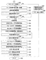
エラー判定回路83は、コントローラ90から指示を受けると作動開始する。エラー判定回路83は、2値化回路と時間計測回路とを備えており、第2信号増幅回路81から入力した受光信号を2値化回路にてハイレベル信号とローレベル信号とからなる2値化信号に変換する。つまり、図2に示すように、受光信号の波高値が予め設定した基準値以上であればハイレベル信号を、基準値未満であればローレベル信号に変換する。そして、時間計測回路を用いて2値化信号のローレベル信号の長さ(連続時間)を計測し、計測した長さが、予め設定した設定長さ(異常判定用基準時間)を超える場合には、ローレベル信号の終了時点(ハイレベル信号に切り替わる時)にエラー検出を表す信号(以下、エラー検出信号と呼ぶ)を出力する。つまり、受光信号の波高値が予め設定した基準値を下回る方向にクロスした場合、その下回った時点から、次に、受光信号の波高値が基準値を上回る方向にクロスするまでの時間を計測し、その計測時間が異常判定用基準時間を超える場合には、エラー検出信号を出力する。この異常判定用基準時間の経過をエラー判定の要件に加えている理由は、瞬時的な信号ノイズの影響を除去するためである。エラー検出信号は、第1データ保存回路61、第2データ保存回路62、第3データ保存回路63に出力される。
The
本実施形態のレーザ加工装置1においては、後述するように、加工対象物OBをセットしたテーブル21を回転させながら半径方向に送り移動させている状態で、加工ヘッド30の第1レーザ光源31から加工用レーザ光を照射することにより加工対象物OBの表面をレーザ加工する。レーザ光は、発光信号供給回路73からの信号にしたがって照射される。このため、連続照射であれば加工対象物OBの表面に連続した微細溝が螺旋状に形成され、断続照射であれば、加工対象物OBの表面に複数の微細ピットが螺旋状に配置されて形成される。従って、加工ヘッド30から照射される加工用レーザ光の強度は、一定の場合もあれば、パルス状の波形になる場合もある。また、レーザ加工を最適に行うために、加工用レーザ光の強度は、コントローラ90から第1レーザ駆動回路71への指令により適宜調整される。
In the
加工対象物OBの表面に異物が付着していたり傷が形成されていたりすると、その部分(以下、異物付着部や傷の形成部を異常部と呼ぶ)については適正にレーザ加工できない。レーザ加工不良の原因は、ほとんどの場合、こうした加工対象物OBに起因する。加工対象物OBの表面に異物が付着していたり傷が形成されていたりすると、レーザ光の反射光強度が下がる。従って、レーザ光の反射光強度に基づいて加工対象物OBの異常を検出することができる。 If foreign matter adheres to the surface of the processing object OB or a scratch is formed, the portion (hereinafter, the foreign matter adhesion portion or the scratch formation portion is referred to as an abnormal portion) cannot be appropriately laser processed. In most cases, the cause of the laser processing failure is due to such a processing object OB. If foreign matter adheres to the surface of the processing object OB or a flaw is formed, the reflected light intensity of the laser light decreases. Therefore, it is possible to detect an abnormality of the processing object OB based on the reflected light intensity of the laser light.
この場合、加工用レーザ光の反射光強度の低下に基づいて異常を検出しようとすると、高い検出精度を得ることができない。なぜなら、加工対象物OBにピットを形成する場合には、パルス状のレーザ光を加工対象物OBに照射するため、その反射光強度も強弱がハンチングし、異常判定するための基準値(閾値)を適切に設定することが難しいからである。また、加工対象物OBの種類やレーザ加工の種類によってもレーザ光の強度が適宜調整されるため、この点においても異常判定するための基準値の設定は難しい。 In this case, high detection accuracy cannot be obtained if an abnormality is detected based on a decrease in the reflected light intensity of the processing laser light. This is because, when pits are formed on the workpiece OB, a pulsed laser beam is irradiated onto the workpiece OB, and therefore the intensity of the reflected light is hunted and the reference value (threshold value) for determining abnormality. It is because it is difficult to set up appropriately. Further, since the intensity of the laser beam is appropriately adjusted depending on the type of the processing object OB and the type of laser processing, it is difficult to set a reference value for determining an abnormality also in this respect.
そこで本実施形態においては、レーザ加工されない一定強度の検査用レーザ光を出射する第2レーザ光源を加工ヘッド30に設け、その検査用レーザ光の反射光の強度に基づいて異常を検出する構成を採用している。この場合には、検査用レーザ光の強度が一定であるため、反射光強度を比較する異常判定用の基準値の設定が容易となる。
Therefore, in the present embodiment, a configuration is provided in which a second laser light source that emits laser light for inspection with a constant intensity that is not laser processed is provided in the
加工対象物OBの表面に異常部が存在すると、反射光強度を表す受光信号の波高値が基準値を下回る(図2の時刻t1)。そして、検査用レーザ光の照射位置が異常部を通過し終えると、受光信号の波高値が復帰して基準値を上回る(図2の時刻t2)。エラー判定回路83においては、受光信号の波高値が基準値を下回っている期間(時刻t1から時刻t2までの期間)だけ2値化回路からローレベル信号を出力し、時間計測回路によりローレベル信号の長さ(連続時間)を計測する。そして、ローレベル信号の長さが設定長さ(異常判定用基準時間)を越える場合には、受光信号の波高値が基準値にまで復帰した時点でエラー検出信号を出力する。
When an abnormal part exists on the surface of the processing object OB, the peak value of the received light signal indicating the reflected light intensity falls below the reference value (time t1 in FIG. 2). Then, when the irradiation position of the inspection laser beam finishes passing through the abnormal part, the peak value of the received light signal returns and exceeds the reference value (time t2 in FIG. 2). In the
尚、稀ではあるが、異常部の種類によっては、反射光強度のレベルが上昇する場合がある。そこで、上記基準値(以下、第1基準値と呼ぶ)と、それよりも高いレベルとなる第2基準値との2つの基準値を用いて、受光信号の波高値を比べるようにしてもよい。例えば、エラー判定回路83に、上記2つの基準値の間を正常範囲として、受光信号の波高値がこの正常範囲に入っているときにハイレベル信号を出力し、正常範囲から外れているときにローレベル信号を出力する2値化回路を設ける。そして、2値化回路がローレベル信号を出力し、そのローレベル信号が設定長さ(異常判定用基準時間)を越えた場合に、2値化回路がハイレベル信号に切り替わった時点でエラー検出信号を出力する。
Although rare, the level of reflected light intensity may increase depending on the type of abnormal part. Therefore, the peak values of the received light signals may be compared using the two reference values, the reference value (hereinafter referred to as the first reference value) and the second reference value that is higher than the reference value. . For example, the
第1データ保存回路61は、コントローラ90から指示を受けると作動開始する。第1データ保存回路61は、内部にメモリを備え、A/D変換器82から出力される反射光の強度(波高値に相当する)を表すデジタルデータをメモリに逐次記憶していき、記憶したデジタルデータのデータ数が設定数N(例えば、10万個)に達すると、再び、その先頭の記憶領域(最も古いデータの記憶されている記憶領域)から順番に最新のデジタルデータを記憶していく(上書き)。第1データ保存回路61は、N個のデジタルデータを記憶する記憶領域を1つの記憶ブロックとして、複数の記憶ブロックを備えている。そして、エラー判定回路83からエラー検出信号が出力されていないあいだは、第1記憶ブロックのみを使って、最新のN個分の反射光の強度を表すデジタルデータを記憶し、エラー判定回路83からエラー検出信号が入力すると、その記憶ブロックのなかの最も新しいデジタルデータが記憶されている記憶領域、つまり、最後に記憶したデジタルデータの記憶領域の次の記憶領域(あるいは所定数あとの記憶領域)に識別フラグデータを記憶し、それ以降、第1記憶ブロックにはデータ記憶を行わないようにする。
The first
第1データ保存回路61は、第1記憶ブロックに識別フラグデータを記憶すると、以降、第2記憶ブロックを使って、A/D変換器82から出力されるデジタルデータを、その先頭の記憶領域から逐次記憶していく。そして、エラー判定回路83からエラー検出信号が入力するたびに、識別フラグデータを、最後に記憶したデジタルデータの記憶領域の次の記憶領域に記憶し、データ記憶するための記憶ブロックを新たな記憶ブロックに変更する。
When the first
このようにして、第1データ保存回路61は、エラー検出信号を入力するたびに、エラー検出信号入力直前の最大で(N−1)個のデジタルデータを記憶する。従って、各記憶ブロックに記憶されたデジタルデータから、反射光の強度の履歴(エラー検出信号を入力するまでの所定期間の履歴)がわかるようになっており、この反射光の強度の履歴から受光信号の波高値が基準値を下回った時点(図2の時刻t1)も検出することができる。第1データ保存回路61は、コントローラ90からデータ出力指令が入力すると、各記憶ブロックに記憶したデジタルデータをコントローラ90へ出力する。以下、第1データ保存回路61に記憶されたデジタルデータを波高値データと呼ぶ。
In this way, each time the error detection signal is input, the first
第2データ保存回路62は、コントローラ90から指示を受けると作動開始する。第2データ保存回路62は、内部にメモリを備え、回転角度検出回路51から入力される回転角度に相当するデジタルデータを、エラー判定回路83からエラー検出信号が入力するたびに記憶する。そして、コントローラ90からデータ出力指令が入力すると、メモリに記憶したデジタルデータをコントローラ90へ出力する。以下、第2データ保存回路62に記憶されたデジタルデータを回転角度データと呼ぶ。
The second
第3データ保存回路63は、コントローラ90から指示を受けると作動開始する。第3データ保存回路63は、内部にメモリを備え、半径位置検出回路52から入力される半径位置(テーブル21の半径方向への送り位置)に相当するデジタルデータを、エラー判定回路83からエラー検出信号が入力するたびに記憶する。そして、コントローラ90からデータ出力指令が入力すると、メモリに記憶したデジタルデータをコントローラ90へ出力する。以下、第3データ保存回路63に記憶されたデジタルデータを半径位置データと呼ぶ。
The third
このように、第1,第2,第3データ保存回路61,62,63を設けたことにより、加工対象物OBに存在する異常部の位置を特定することができる。つまり、加工対象物OBの異常部の回転方向位置(テーブル21の回転方向における位置)を第2データ保存回路62に記憶した回転角度データから特定でき、半径方向の位置(加工対象物OBの中心から半径方向の距離)を第3データ保存回路63に記憶した半径位置データから特定できる。この位置は、エラー判定回路83からエラー検出信号が出力された時点におけるレーザ光の照射位置となるため、異常部の終了位置を特定するものである。以下、異常部の終了位置における加工対象物OBの回転中心(テーブル21の回転中心と等しい)からの距離をエラー位置半径rとよび、基準回転位置に対する加工対象物OBの回転角度(テーブル21の回転角度)をエラー位置角度θと呼ぶ。また、このエラー位置半径rとエラー位置角度θにより特定される異常部の終了位置(r、θ)をエラー検出点と呼ぶ。
As described above, by providing the first, second, and third
一方、第1データ保存回路61には、エラー判定回路83からエラー検出信号が出力される直前の波高値データの履歴が記憶されているため、この履歴を参照して、異常部の回転方向における長さ(円弧の長さ、以下、エラー長さLと呼ぶ)を特定することができる。つまり、記憶されている波高値データのうち、波高値が基準値よりも下回っている期間が、エラー長さLに対応したものとなる。エラー長さLは、波高値が基準値より下回っているデータの数をu、第1データ保存回路61に波高値データが記憶されるサンプリング間隔をt(秒)、加工対象物OBに対するレーザスポットの回転線速度をvとすると、L=u×t×vにて求めることができる。
On the other hand, since the first
コントローラ90は、第1,第2,第3データ保存回路61,62,63に記憶された波高値データ,回転角度データ,半径位置データを取り込み、上述したような演算処理を行うことにより、加工対象物OBの異常部の位置を求める。このコントローラ90は、CPU、ROM、RAMを備えたマイクロコンピュータと、ハードディスクや不揮発性メモリなどの記憶装置と、入出力インタフェース等から構成される電子制御装置である。コントローラ90には、作業者が各種パラメータや処理等を指示するための入力装置91と、作業者に対して検査結果や作動状況等を視覚的に知らせるための表示装置92とが接続されている。
The
次に、レーザ加工装置1の動作を説明する。作業者は、レーザ加工装置1の図示しない電源スイッチをオンして、図1に示す各種回路の作動を開始させる。電源投入時には、コントローラ90は、図示しないプログラムの実行により、半径位置検出回路52およびフィードモータ制御回路54に対して初期設定を指示する。この指示によりフィードモータ制御回路54は、フィードモータ23を回転させてテーブル21を駆動限界位置である初期位置に移動させる。テーブル21が初期位置まで達してフィードモータ23の回転が停止すると、半径位置検出回路52はエンコーダ23aからのパルス列信号の入力停止を検出して、カウント値を「0」にリセットし、フィードモータ制御回路54に出力停止のための信号を出力して初期設定が完了する。
Next, the operation of the
次に、コントローラ90は、図示しないプログラムの実行により、表示装置92を用いて、加工対象物OBの加工に必要な加工データの入力を作業者に促す。作業者は、入力装置91を用いて、加工対象物OBのシリアルナンバー、レーザ加工開始半径位置、レーザ加工終了半径位置、半径方向の加工ピッチ、加工対象物OBに対するレーザスポットの回転線速度、溝加工またはピット加工の指定、ピット加工の場合には回転方向のピット間隔などを入力する。コントローラ90は、入力された加工データを内部の記憶装置に記憶する。尚、加工データがコントローラ90内に記憶されている場合には、この処理を省略してもよい。
Next, the
このような初期処理の実行後、レーザ加工ルーチンが開始される。図3は、レーザ加工ルーチンを示すフローチャートである。このレーザ加工ルーチンは、コントローラ90のROM内に制御プログラムとして記憶されており、ステップS10にて開始される。コントローラ90は、まず、ステップS12において、フィードモータ制御回路54に前記入力されたレーザ加工開始半径位置に移動するように指示する。フィードモータ制御回路54は、半径位置検出回路52によって検出された半径位置を入力しながら、レーザ光の照射位置がレーザ加工開始半径位置に一致するまで、フィードモータ23の回転を制御してテーブル21を移動する。半径位置検出回路52によって検出された半径位置がレーザ加工開始半径位置に等しくなると、フィードモータ制御回路54はフィードモータ23の回転を停止する。これにより、レーザ光の照射位置がレーザ加工開始半径位置にまで移動する。
After execution of such initial processing, a laser processing routine is started. FIG. 3 is a flowchart showing a laser processing routine. This laser processing routine is stored as a control program in the ROM of the
続いて、コントローラ90は、ステップS14において、前記入力されたレーザ加工開始半径位置および回転線速度を用いて、スピンドルモータ22の回転速度を計算し、この計算した回転速度をスピンドルモータ制御回路53に出力するとともにスピンドルモータ22の回転開始を指示する。スピンドルモータ制御回路53は、エンコーダ22aからのA相信号およびB相信号を用いてスピンドルモータ22の回転速度を計算し、この計算した回転速度がコントローラ90から入力された回転速度に等しくなるようにスピンドルモータ22の回転制御を開始する。尚、コントローラ90は、回転開始指示を出力した後は、本ルーチンとは別の割り込みルーチンにより、スピンドルモータ22の回転速度の計算を繰り返し、その都度、計算した回転速度をスピンドルモータ制御回路53に出力する。
Subsequently, the
続いて、コントローラ90は、ステップS16において、第1レーザ駆動回路71に対して非加工用レーザ光照射の開始を指示する。これにより、第1レーザ駆動回路71は、第1レーザ光源31に対して、非加工レベルの駆動信号の出力を開始する。第1レーザ光源31は、この駆動信号により非加工用レーザ光を出射する。これにより加工対象物OBの表面に非加工用レーザ光の光スポットが形成され、この光スポットの反射光が第1フォトディテクタ39によって検出される。この場合、加工対象物OBは、非加工用レーザ光の照射によっては加工されない。
Subsequently, in step S16, the
続いて、コントローラ90は、ステップS18において、フォーカスサーボ回路76と図示していないフォーカスアクチュエータ40を駆動する回路とS字検出回路に作動開始を指示する。第1フォトディテクタ39によって検出された反射光に応じた受光信号は第1信号増幅回路74を介してフォーカスエラー信号生成回路75に供給されており、フォーカスエラー信号生成回路75は光スポットからの反射光に応じたフォーカスエラー信号をフォーカスサーボ回路76に出力している。フォーカスアクチュエータ40が駆動するとレーザ光の焦点位置が加工対象物OBの表面に一致する近傍でフォーカスエラー信号(a’+c’)−(b’+d’)がS字状に変化する。このS字状に変化する範囲の中間付近のタイミングで、フォーカスサーボ回路76は、フォーカスエラー信号(a’+c’)−(b’+d’)の値が一定値(例えば、ゼロ)になるように、ドライブ回路77に制御信号を出力してフォーカスアクチュエータ40の駆動制御を開始する。つまり、レーザ光の焦点位置が加工対象物OBの表面に一致するように、第1レーザ光源31から出射されるレーザ光の光軸方向に対物レンズ36を駆動する。
Subsequently, in step S18, the
続いて、コントローラ90は、ステップS20において、第2レーザ駆動回路72に対して検査用レーザ光の照射開始を指示する。これにより、第2レーザ駆動回路72は、第2レーザ光源41に対して、検査レベルの一定の駆動信号の出力を開始する。第2レーザ光源41は、この駆動信号により検査用レーザ光を出射する。これにより加工対象物OBの表面に検査用レーザ光の光スポットが、非加工用レーザ光の光スポットに近接して形成され、その反射光が第2フォトディテクタ45によって検出される。この場合、加工対象物OBは、検査用レーザ光の照射によっては加工されない。
Subsequently, the
続いて、コントローラ90は、ステップS22において、第1レーザ駆動回路71に対して加工用レーザ光の照射開始を指示し、発光信号供給回路73に信号の出力を指示する。これにより、第1レーザ駆動回路71は、第1レーザ光源31に出力していた駆動信号を、非加工レベルから加工レベルに切り替え、発光信号供給回路73から供給される信号の波形に応じた波形にする。こうして、第1レーザ光源31は、加工レベルに対応した加工用レーザ光を出射する。従って、加工対象物OBには加工用レーザ光が照射され、加工対象物OBのレーザ加工が開始される。
Subsequently, in step S <b> 22, the
第2レーザ光源41から出射される検査用レーザ光の光軸は、第1レーザ光源31から出射される加工用レーザ光の光軸に対して加工対象物OBの回転方向とは逆方向に僅かに傾けられている。このため、加工対象物OBの表面に形成される検査用レーザ光の光スポットと加工用レーザ光の光スポットとは重ならず、検査用レーザ光の光スポット位置が、加工用レーザ光の光スポットの加工方向の僅かに前方位置となる。従って、検査用レーザ光は、加工用レーザ光により加工対象物OBがレーザ加工される直前位置を照射することになる。換言すれば、加工対象物OBの表面において、検査用レーザ光の光スポット位置の移動軌跡を後からトレースするように加工用レーザ光の光スポット位置が移動する。
The optical axis of the inspection laser beam emitted from the second
続いて、コントローラ90は、ステップS24において、フィードモータ制御回路54に対して、半径方向への移動開始を指示する。この場合、コントローラ90は、前記入力された回転線速度および加工ピッチ、半径位置検出回路52から取り込んだ半径位置に基づいて移動速度を計算し、フィードモータ制御回路54に対して移動速度を指示する。フィードモータ制御回路54は、エンコーダ23aからのA相信号およびB相信号を用いてフィードモータ23の半径方向の移動速度を計算し、この計算した移動速度がコントローラ90から指示された移動速度に等しくなるようにフィードモータ23の回転を制御する。この結果、テーブル21は、指示された移動速度で半径方向に移動し始める。尚、コントローラ90は、半径方向への移動開始を指示した後は、本ルーチンとは別の割り込みルーチンにより、テーブル21の移動速度の計算を繰り返し、その都度、計算した移動速度をフィードモータ制御回路54に出力する。
Subsequently, in step S24, the
こうして、テーブル21の回転と半径方向への移動とにより、加工対象物OBと加工ヘッド30との相対位置が変化し、加工用レーザ光と検査用レーザ光の照射位置が加工対象物OBの表面を螺旋状に移動していく。従って、加工用レーザ光の照射軌跡に沿って加工対象物OBの表面にレーザ加工が施されると同時に、レーザ加工直前の加工対象物OBの表面に検査用レーザ光が照射される。
Thus, the relative position between the processing object OB and the
続いて、コントローラ90は、ステップS26において、エラー判定回路83、クロック信号発生回路84、回転角度検出回路51に対して作動開始の指示を行うとともに第1〜第3データ保存回路61,62,63に対して記憶開始の指示を行う。この指示により、加工対象物OBの異常検査が開始される。エラー判定回路83は、コントローラ90からの指示により作動開始し、第2フォトディテクタ45で受光された検査用レーザ光の受光信号を第2信号増幅回路81を介して入力し、受光信号の波高値と予め設定した異常判定用の基準値とを比較する。そして、波高値が基準値を下回っている連続時間が設定時間を超える場合には、加工対象物OBの表面に異常部が存在していると判定する。異常部が存在していると判定した場合には、波高値が基準値に到達したときにエラー検出信号を第1〜第3データ保存回路61,62,63に出力する。
Subsequently, in step S26, the
クロック信号発生回路84は、コントローラ90からの指示により作動開始し、A/D変換器82にクロック信号を出力する。これにより、A/D変換器82は、クロック信号に基づくサンプリング周期で、第2信号増幅回路81から出力される受光信号の波高値をデジタルデータの波高値データに変換して第1データ保存回路61に出力する。第1データ保存回路61も、コントローラ90からの指示により作動を開始して、A/D変換器82から出力される波高値データをメモリに逐次記憶していく。第1データ保存回路61は、上述したようにエラー検出信号を入力していないあいだは、第1記憶ブロックのみを使って最新N個分の波高値データを記憶し、エラー検出信号が入力するたびに、識別フラグデータを、最後に記憶した波高値データの記憶領域の次の記憶領域に記憶し、データ記憶するための記憶ブロックを新たな記憶ブロックに変更していく。
The clock
回転角度検出回路51は、コントローラ90からの指示により作動開始し、エンコーダ22aから出力されるパルス列信号のパルス数のカウント値からテーブル21の回転角度を計算し、回転角度を表すデジタルデータ(回転角度データ)を第2データ保存回路62とコントローラ90とに出力する。第2データ保存回路62も、コントローラ90からの指示により作動を開始して、回転角度検出回路51から出力される回転角度データを入力する。そして、エラー判定回路83からエラー検出信号が入力するたびに、そのときの回転角度データをメモリに記憶していく。
The rotation
第3データ保存回路63は、コントローラ90からの指示により作動を開始して、半径位置検出回路52から出力されるデジタルデータ(半径位置データ)を入力する。そして、エラー判定回路83からエラー検出信号が入力するたびに、そのときの半経位置データをメモリに記憶していく。
The third
続いて、コントローラ90は、ステップS28において、半径位置検出回路52から出力される半径位置データを取り込み、ステップS30において、加工終了半径位置に到達したか否かを判断する。加工終了半径位置は、作業者がレーザ加工開始にあたって入力設定した値である。ステップS28,S30の処理は、半径位置検出回路52により検出される半径位置が加工終了半径位置に一致するまで繰り返される。従って、この間は、加工用レーザ光照射による加工対象物OBのレーザ加工と、検査用レーザ光照射による加工対象物OBの異常検査が同時に継続されることとなる。
Subsequently, the
半径位置検出回路52により検出される半径位置が加工終了半径位置に達すると(S30:Yes)、コントローラ90は、ステップS32において、フォーカスサーボ回路76に作動停止を指示して、フォーカスサーボ回路76によるフォーカスサーボ制御を停止させる。次に、コントローラ90は、ステップS34において、第2レーザ駆動回路72に対して検査用レーザ光の照射停止を指示する。これにより、第2レーザ駆動回路72は、それまで第2レーザ光源41に出力していた検査レベルの駆動信号の出力を停止する。従って、加工対象物OBの表面に照射されていた検査用レーザ光の照射が停止される。
When the radius position detected by the radius
続いて、コントローラ90は、ステップS36において、第1レーザ駆動回路71に対して加工用レーザ光の照射停止を指示する。これにより、第1レーザ駆動回路71は、第1レーザ光源31に出力していた加工レベルの駆動信号の出力を停止する。従って、それまで加工対象物OBの表面に照射されていた加工用レーザ光の照射が停止される。
Subsequently, the
続いて、コントローラ90は、ステップS38において、エラー判定回路83、クロック信号発生回路84に対して作動停止を指示する。これにより、エラー判定回路83は、検査用レーザ光の反射強度に基づく異常判定処理を停止する。また、クロック信号発生回路84は、A/D変換器82に出力していたクロック信号を停止する。従って、A/D変換器82は、波高値データを第1データ保存回路61に出力しなくなる。続いて、コントローラ90は、ステップS39において、スピンドルモータ制御回路53に対して回転停止を指示する。これにより、スピンドルモータ制御回路53は、スピンドルモータ22の回転駆動を停止し、スピンドルモータ22の回転は停止する。
Subsequently, in step S38, the
続いて、コントローラ90は、ステップS40において、第1〜第3データ保存回路61,62,63に対してデータ記憶の停止を指示するとともに、第1〜第3データ保存回路61,62,63に記憶されている波高値データ、回転角度データ、半径位置データをコントローラ90内のメモリ(RAM)に取り込む。これに伴って、第1〜第3データ保存回路61,62,63に記憶されていた各データは消去される。続いて、コントローラ90は、ステップS42において、エラーデータが存在するか否かを判断する。上述した加工対象物OBの検査中にエラー判定回路83からエラー検出信号が出力された場合、第2データ保存回路62、第3データ保存回路63には回転角度データ、半径位置データがそれぞれ記憶される。従って、先のステップS40にて第2データ保存回路62、第3データ保存回路63からデータを取り込んだときに、回転角度データ、半径位置データが存在していた場合にはエラーデータが存在していると判定し、回転角度データ、半径位置データが存在していなかった場合にはエラーデータが存在していないと判定する。コントローラ90は、エラーデータが存在しないと判断した場合(S42:No)、ステップS44において、回転角度検出回路51に作動停止を指示する。これにより、回転角度検出回路51は、その作動を停止する。そして、ステップS46において、エラーが存在しなかったことを表示装置92に表示して本加工制御ルーチンを終了する。
Subsequently, in step S40, the
一方、エラーデータが存在している場合には(S42:Yes)、コントローラ90は、その処理をステップS48に進めて、フィードモータ制御回路54に対して、マーク目標半径位置にまで移動するように指示する。このマーク目標半径位置は、加工対象物OBの半径位置から所定距離aだけ引いた値に設定される。つまり、マーク目標半径位置は、加工対象物OBの外周ラインから加工対象物OBの中心側に向けて半径方向に所定距離aだけ内側となる位置である。この距離aは微少値に設定されているため、マーク目標半径位置は、加工対象物OBの外周部となる。フィードモータ制御回路54は、コントローラ90からマーク目標半径位置が指示されると、半径位置検出回路52によって検出された半径位置を入力しながらフィードモータ23の回転を制御して、加工用レーザ光の照射位置がマーク目標半径位置に一致するまでテーブル21を移動する。
On the other hand, if error data exists (S42: Yes), the
続いて、コントローラ90は、ステップS50において、スピンドルモータ制御回路53に対して予め設定した超低速回転での回転開始を指示する。スピンドルモータ制御回路53は、超低速回転の設定回転速度が指示されると、その設定回転速度にてスピンドルモータ22を回転駆動する。尚、超低速回転とは、回転停止指令がスピンドルモータ22に入力したときに、瞬時にスピンドルモータ22の回転を停止できる回転速度である。
Subsequently, in step S50, the
続いて、コントローラ90は、ステップS52において、回転角度検出回路51によって検出された回転角度を取り込む。そして、ステップS54において、その検出した回転角度(回転角度位置)が回転角度A以下になったか否かを判断する。この回転角度Aは、基準回転位置(回転角度ゼロ)に極めて近い値に設定されている。コントローラ90は、回転角度検出回路51によって検出した回転角度が回転角度A以下になるまでステップS52,S54の処理を繰り返す。コントローラ90は、回転角度Aが回転角度A以下になると、ステップS56において、スピンドルモータ制御回路53に対して回転停止を指示する。スピンドルモータ制御回路53は、この指示によりスピンドルモータ22を停止させる。スピンドルモータ22は、超低速で回転しているため瞬時に停止する。従って、テーブル21は、その回転位置が実質的に基準回転位置(回転角度ゼロの位置)にて停止することになる。尚、回転角度Aは、回転角度検知から停止までの僅かな遅れや分解能を考慮した角度であって、テーブルを実質的に基準回転位置で停止できればゼロに設定してもよい。
Subsequently, the
続いて、コントローラ90は、ステップS58において、第1レーザ駆動回路71に対して非加工用レーザ光照射の開始を指示し、ステップS60において、フォーカスサーボ回路76に作動開始を指示する。続いて、ステップS62において、第1レーザ駆動回路71に対して加工用レーザ光の照射開始を指示する。これにより、第1レーザ駆動回路71は、第1レーザ光源31に出力していた駆動信号を、非加工レベルから加工レベルに切り替える。このステップS58,S60,S62の処理は、ステップS16,S18,S22の処理と同じである。
Subsequently, the
続いて、コントローラ90は、ステップS64において、フィードモータ制御回路54に対して、移動速度Fにて半径方向(径方向外側)への移動開始を指示する。これにより、フィードモータ制御回路54は、エンコーダ23aからの回転検出信号からテーブル21の半径方向の移動速度を計算して、計算された移動速度がコントローラ90によって指定された移動速度Fと等しくなるようにフィードモータ23の回転制御を開始する。
Subsequently, in step S64, the
続いて、コントローラ90は、ステップS66において、半径位置検出回路52から半径位置データを取り込み、ステップS68において、検出された半径位置が加工対象物OBの半径rkと一致するか否かを判定する。半径位置が加工対象物OBの半径rkと一致するまで、ステップS66,S68の処理が繰り返される。この期間においては、テーブル21が半径方向(径方向外側)に移動するとともに、加工用レーザ光が加工対象物OBに照射されることになる。従って、加工対象物OBのマーク目標半径位置から半径方向に加工用レーザ光の光スポット位置が移動していく。つまり、マーク目標半径位置から半径方向に向かってレーザ加工が直線状に施されていく。
Subsequently, the
コントローラ90は、ステップS68において、半径位置が加工対象物OBの半径rkと一致したと判断すると、続いて、ステップS70において、フォーカスサーボ回路76にフォーカスサーボ制御の停止を指示する。続いて、ステップS72において、第1レーザ駆動回路71に対して加工用レーザ光の照射停止を指示する。これにより、第1レーザ駆動回路71は、第1レーザ光源31に出力していた駆動信号を停止する。こうして、加工対象物OBへのマーク付けが終了する。加工対象物OBのマークは、テーブル21の基準回転位置において、マーク目標半径位置から加工対象物OBの外周端まで直線状に形成される。
If the
続いて、コントローラ90は、ステップS74において、回転角度検出回路51に作動停止を指示する。これにより、回転角度検出回路51は、その作動を停止する。こうして加工対象物OBのレーザ加工処理、マークの形成処理、異常の検出処理が終了する。
Subsequently, the
続いて、コントローラ90は、加工対象物OBにおける異常部の領域を表す異常情報の作成・表示処理に入る。コントローラ90は、先のステップS40にて、波高値データ、回転角度データ、半径位置データをメモリ内に取り込んでいる。このうち、半径位置データと回転角度データは、エラー検出信号がエラー判定回路83から出力されるたびに、その時点における半径位置(エラー位置半径r)と回転角度(エラー位置角度θ)を記憶したデータであり、各異常部の終了位置を特定するエラー検出点(r,θ)情報となる。
Subsequently, the
一方、波高値データは、エラー検出信号が出力されたときの波高値(光強度)の履歴であって、エラー検出のたびに、その直近の最大で(N−1)個の波高値を表すデジタルデータを記憶ブロックに分けてグループ化したものである。従って、波高値データの各グループは、その記憶ブロック順に、回転角度データ、半径位置データと対応したものとなる。そして、各グループにおける波高値データのうち、波高値が基準値を下回っている連続時間が、異常部の回転方向のエラー長さLに対応したものとなる。 On the other hand, the peak value data is a history of peak values (light intensity) when an error detection signal is output, and represents the maximum (N-1) peak values at the nearest time each time an error is detected. This is a group of digital data divided into storage blocks. Therefore, each group of peak value data corresponds to rotation angle data and radius position data in the order of the storage blocks. In the peak value data in each group, the continuous time in which the peak value is below the reference value corresponds to the error length L in the rotation direction of the abnormal part.
コントローラ90は、ステップS76において、波高値データのグループごとに、波高値が基準値より下回っているデータの数(詳しくは、波高値データの一番新しいものから古い方に遡って波高値が連続して基準値を下回っているデータの数)をカウントし、次式により、回転方向のエラー長さLを計算する。
L=u×t×v
ここで、uは波高値が基準値より下回っているデータの数、tは第1データ保存回路61に波高値データが記憶されるサンプリング間隔(秒)、vは加工対象物OBに対するレーザスポットの回転線速度である。このエラー長さLの計算は、波高値データのグループの全てに対して行う。これにより、各エラー検出点(r,θ)に対応したエラー長さLが求められる。尚、上記式においては、正確にはuに代えて(u−1)とすべきであるが、波高値データの数uが大きな値となるので、uと(u−1)とを同一の値として扱っている。
In step S76, the
L = u × t × v
Here, u is the number of data whose peak values are below the reference value, t is the sampling interval (seconds) at which the peak value data is stored in the first
続いて、コントローラ90は、ステップS78において、エラー長さLを使って異常部の開始位置であるエラー開始点(r,θ’)を計算する。この場合、半径方向の加工ピッチが回転方向の移動距離に対して非常に短いため、エラー開始点におけるエラー位置半径をエラー検出点(異常部の終了位置)におけるエラー位置半径rと同一の値として扱っている。エラー開始点におけるエラー位置角度θ’は、ラジアン単位では次式により求めることができる。
θ’=θ−(L/r)
Subsequently, in step S78, the
θ ′ = θ− (L / r)
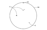
従って、エラー検出点とエラー開始点とを、(r,θ),(r,θ’)として求めることができる。この2つの点をX−Y座標にて表すと(r sinθ,r cosθ),(r sinθ’,r cosθ’)となる。この座標値の集合により、図4に示すように、加工対象物OBにおける異常部の位置と大きさ(以下、エラー箇所と呼ぶ)がわかる。コントローラ90は、エラー検出点(r,θ)とエラー開始点(r,θ’)とを加工対象物OBのシリアルナンバーと対応させて、エラー箇所情報(異常箇所情報)として記憶装置に記憶する。
Therefore, the error detection point and the error start point can be obtained as (r, θ), (r, θ ′). When these two points are expressed in XY coordinates, they are (r sin θ, r cos θ), (r sin θ ′, r cos θ ′). From the set of coordinate values, as shown in FIG. 4, the position and size of the abnormal part (hereinafter referred to as an error part) in the workpiece OB can be known. The
続いて、コントローラ90は、ステップS80において、エラー箇所情報を用いて表示装置92に加工対象物OBにおけるエラー箇所(異常部の領域)を表示する。この場合、図5に示すように、加工対象物OBの輪郭の中に、エラー箇所EとマークMとの両方を表示する。マークMの回転角度位置は0であるため、マーク先端のX−Y座標における座標位置は、(0,rk)として表すことができる(rkは加工対象物OBの半径値)。また、加工対象物OBの中心はX−Y座標における座標原点(0,0)である。従って、マークMを加工対象物OBに形成することにより、この2点から加工対象物OBの表面におけるX,Y座標軸が定まり、加工対象物OBをテーブル21から取り出した後においても、加工対象物OBのエラー箇所Eを特定することができる。
Subsequently, in step S80, the
コントローラ90は、表示装置92によりエラー箇所の表示を所定時間行うと、ステップS82にて本レーザ加工ルーチンを終了する。作業者は、レーザ加工ルーチンが終了するとテーブル21から加工対象物OBを取り外す。そして、次の加工対象物OBのレーザ加工を行う場合には、その加工対象物OBをテーブル21にセットし、必要に応じて加工条件を変更してからレーザ加工の開始を指示する。
When the
本実施形態のレーザ加工装置1においては、加工対象物OBのエラー箇所情報が、加工対象物OBのシリアルナンバーと対応してコントローラ90の記憶装置に記憶される。従って、作業者は、レーザ加工の終了後において、いつでも、入力装置91を使ってエラー箇所を表示装置92に表示させることができるようになっている。このため、上述したレーザ加工ルーチンに、ステップS46やステップS80の表示処理を組み込まないようにしてもよい。
In the
加工対象物OBの異常の有無は、マークの有無により判断することができる。加工対象物OBの外周部にマークが形成されていなければ、異常部が存在しないといえる。従って、レーザ加工終了後においては、加工対象物OBのマークの有無を確認するだけで、異常の有無を簡単に確認することができる。また、作業者は、マークが形成されている加工対象物OBについて、エラー箇所を表示装置92に表示させることにより、そのマークを基準とした異常部の位置を認識することができる。加工対象物OBは、最終的には、複数に分割して製品とされる場合が多い。従って、複数に分割するときに、異常部の存在する部分を除外することで、加工対象物OB全体を無駄にしてしまうことなく、正常部分を有効に利用することができる。 The presence / absence of abnormality of the workpiece OB can be determined by the presence / absence of a mark. If no mark is formed on the outer periphery of the workpiece OB, it can be said that there is no abnormal part. Therefore, after the laser processing is completed, it is possible to easily check the presence / absence of an abnormality simply by checking the presence / absence of the mark on the workpiece OB. In addition, the operator can recognize the position of the abnormal portion with reference to the mark by displaying the error location on the display device 92 for the workpiece OB on which the mark is formed. In many cases, the workpiece OB is finally divided into a plurality of products. Therefore, when dividing into a plurality of parts, by excluding the part where the abnormal part exists, the normal part can be used effectively without wasting the entire workpiece OB.
以上説明した本実施形態のレーザ加工装置1によれば、加工用レーザ光とは異なる検査用レーザ光を使って、この反射光の強度と基準値との比較により加工対象物OBの異常を検査するため、精度の良い検査を行うことができる。つまり、レーザ加工の種類(ピット形成や連続した溝の形成)や加工用レーザ光の強度に影響されることなく、独立した検査用レーザ光の反射光の強度に基づいて加工対象物OBを検査するため、異常判定用の基準値の設定を適切に行うことができ、誤判定を低減することができる。
According to the
また、この加工対象物OBの検査は、加工対象物OBの表面のレーザ加工状態を検査するものでもある。つまり、レーザ加工状態の異常は、その原因が、加工対象物OBに付着している異物、あるいは、加工対象物OBに形成されている傷など加工対象物OBそのものに起因するものが殆どであり、加工対象物OBの表面に異常がなければレーザ加工状態も正常となる。従って、本実施形態においては、検査用レーザ光の照射スポット位置を、加工用レーザ光の照射スポット位置の加工方向前方直近位置に設定して、加工対象物OBにおけるレーザ加工される直前位置を検査することで、レーザ加工状態の検査を代用できる。このため、加工用レーザ光による加工跡の影響を受けることなく、簡単にしかも精度良く検査を行うことができる。 Further, the inspection of the processing object OB is to inspect the laser processing state of the surface of the processing object OB. That is, most of the abnormalities in the laser processing state are caused by the processing object OB itself, such as foreign matter attached to the processing object OB, or scratches formed on the processing object OB. If there is no abnormality on the surface of the processing object OB, the laser processing state is also normal. Therefore, in the present embodiment, the irradiation spot position of the inspection laser beam is set to the position closest to the front in the processing direction of the irradiation spot position of the processing laser beam, and the position immediately before the laser processing on the processing object OB is inspected. By doing so, inspection of the laser processing state can be substituted. For this reason, it is possible to perform the inspection easily and accurately without being affected by the processing trace by the processing laser beam.
しかも、加工ヘッド30内に第2レーザ光源41、および、その光学系部材を設けているため、加工用レーザ光と検査用レーザ光とにおける光スポットの相対位置が一定となり、しかも、2つの光スポットが接近しているため、加工対象物OBのレーザ加工と検査との位置制御(回転角度、半径位置)を別々に行う必要もない。また、加工用レーザ光と検査用レーザ光とを共通の対物レンズ36から照射させることができ、光学系部材を兼用させることができる。
In addition, since the second
また、加工用レーザ光の照射によるレーザ加工と同時に検査用レーザ光を照射して異常を検出するため、タクトタイムの増加を招くことがなく生産効率を維持することができる。また、検査装置を別途設ける必要がないため、設備コスト、設置スペースも不要となり、製造コストを抑えることができる。 In addition, since the abnormality is detected by irradiating the inspection laser beam simultaneously with the laser processing by the irradiation of the processing laser beam, the production efficiency can be maintained without increasing the tact time. Moreover, since it is not necessary to provide an inspection apparatus separately, an installation cost and installation space become unnecessary, and a manufacturing cost can be suppressed.
また、異常部が検出された加工対象物OBにマークを形成し、このマークを基準としたエラー箇所情報を作成するため、作業者は、このマークを基準として、どの位置にどの程度の大きさの異常部が存在するのかを知ることができる。従って、加工対象物OBにおける異常箇所を把握することができるため、レーザ加工終了後の工程において加工対象物OBを複数に分割して製品を作製する場合には、異常箇所を除いた部分を製品とすることができる。また、レーザ加工時においてマークを形成することができるため、前もってマークが形成された加工対象物OBを用意する必要がなく、また、その加工対象物OBをセット部21にセットするときにマークをセット部21の所定位置に合わせる必要もない。これらの結果、生産効率が一層向上する。
In addition, since a mark is formed on the workpiece OB in which the abnormal part is detected and error location information is created based on the mark, the operator can determine the size and position of the mark on the basis of the mark. It is possible to know whether there is an abnormal part. Therefore, since the abnormal part in the processing object OB can be grasped, when the product is manufactured by dividing the processing object OB into a plurality of parts in the process after the end of the laser processing, the part excluding the abnormal part is the product. It can be. Further, since the mark can be formed at the time of laser processing, it is not necessary to prepare the workpiece OB on which the mark is formed in advance, and the mark is set when the workpiece OB is set on the
また、異常部が検出された加工対象物OBにだけマークを形成するため、マーク形成時間を短縮することができる。また、マークは、加工対象物OBの外周部において直線状に形成されるため、その形成が容易であるだけでなく、作業者にとって識別が容易となる。 Moreover, since the mark is formed only on the workpiece OB in which the abnormal part is detected, the mark formation time can be shortened. In addition, since the mark is formed in a straight line on the outer peripheral portion of the workpiece OB, not only the formation is easy, but also the identification is easy for the operator.
次に、第2実施形態のレーザ加工装置について説明する。上述した第1実施形態においては、テーブル21に1つの加工対象物OBをセットしてレーザ加工するレーザ加工装置について説明したが、第2実施形態のレーザ加工装置は、テーブル21に複数の加工対象物OBをセットして、複数の加工対象物OBに対して同時にレーザ加工と検査とを行う。図6は、第2実施形態としてのレーザ加工装置2の概略構成図、図7は、加工対象物OBのテーブル21へのセット方法を表す説明図、図8は、加工対象物OBがテーブル21にセットされた状態を表す概略斜視図である。
Next, the laser processing apparatus of 2nd Embodiment is demonstrated. In the first embodiment described above, the laser processing apparatus that performs laser processing by setting one processing object OB on the table 21 has been described. However, the laser processing apparatus of the second embodiment includes a plurality of processing objects on the table 21. An object OB is set, and laser processing and inspection are simultaneously performed on a plurality of workpieces OB. FIG. 6 is a schematic configuration diagram of the
加工対象物OBは、第1実施形態と同じ円盤状をなし、固定治具110を介してテーブル21にセットされる。固定治具110は、図7に示すように、加工対象物OBをテーブル21の回転軸まわりに周方向に複数枚(本実施形態では4枚)並べて固定するための円形の固定孔110hが穿設された薄い円盤であり、テーブル21の上面に載置される。各固定孔110hは、その中心(円中心)が固定治具110の中心から半径rcだけ離れた位置に、それぞれ周方向に等間隔(90度)に配置される。加工対象物OBは、全て同一形状であり、固定孔110hに厚さ方向に挿入することにより固定治具110に固定される。
The workpiece OB has the same disk shape as that of the first embodiment, and is set on the table 21 via the fixing
テーブル21の上面には複数の吸引孔21aが形成されており、図示しない吸引装置の作動により、吸引孔21aに負圧を発生させて固定治具110と加工対象物OBとをテーブル21の上面に吸引固定する。固定治具110は、テーブル21に対して固定治具110の中心がテーブル21の中心と一致するように、図示しないガイドにより位置決めされる。
A plurality of suction holes 21 a are formed on the upper surface of the table 21, and a negative pressure is generated in the suction holes 21 a by operating a suction device (not shown) so that the fixing
第2実施形態のレーザ加工装置2の回路構成について説明する。第2実施形態のレーザ加工装置2は、図6に示すように、第1実施形態のレーザ加工装置1に、エッジ検出回路85を備えたもので、他の構成については、第1実施形態のレーザ加工装置1と同じである。従って、第1実施形態と同じ構成要素については、図面に第1実施形態と同一符号を付して説明を省略する。
A circuit configuration of the
エッジ検出回路85は、第2信号増幅回路81から出力される受光信号を入力し、受光信号の波高値が予め設定したエッジ検出用設定値をクロスしたときに、エッジ検出信号をコントローラ90に出力する。つまり、エッジ検出回路85は、受光信号の波高値とエッジ検出用設定値とを比較し、受光信号の波高値がエッジ検出用設定値を下回っている状態から増大してエッジ検出用設定値を上回ったとき、および、受光信号の波高値がエッジ検出用設定値を上回っている状態から減少してエッジ検出用設定値を下回ったときに、それぞれエッジ検出信号として所定幅の1つのパルス信号をコントローラ90に出力する。
The
加工対象物OBの表面と固定治具110の表面との光の反射率は相違し、本実施形態においては、固定治具110の表面のほうが加工対象物OBの表面より光の反射率が高い。従って、第2レーザ光源41から検査用レーザ光を出射している状態でテーブル21を回転させると、第2信号増幅回路81の出力する受光信号の波高値が、加工対象物OBのエッジ箇所(外周縁)で変化する。従って、固定治具110の表面の反射光における波高値と、加工対象物OBの表面の反射光における波高値との中間値をエッジ検出用設定値として予め設定しておくことで、検査用レーザ光の光スポットが加工対象物OBのエッジを通過したときに、確実にエッジ検出信号を出力させることができる。
The light reflectance of the surface of the processing object OB and the surface of the fixing
尚、エラー判定回路83において、上述したように、波高値が上昇する異常部に対応するために、第1基準値と第1基準値よりも高い第2基準値との間を正常範囲として、受光信号の波高値がこの正常範囲から外れているときにローレベル信号を出力する2値化回路を設けた構成を採用する場合には、波高値が第2基準値を上回った場合であっても波高値がエッジ検出用設定値を上回った場合にはエラー検出信号の出力を禁止するとよい。これは、検査用レーザ光が固定治具110を照射しているときにエラー検出信号を出力しないようにするためである。
In addition, in the
この第2実施形態においては、作業者は、レーザ加工装置2でレーザ加工を行うにあたって、まず、テーブル21の上面に固定治具110を載置して吸着させる。このとき、固定治具110は、図示しないガイドにより、テーブル21の中心と固定治具110の中心とが一致するように位置決めされる。そして、作業者は、固定治具110の固定孔110hに加工対象物OBを一つずつ挿入してテーブル21に吸着させる。こうして、テーブル21の回転軸を中心とした同一円周上に加工対象物OBが配置固定される。
In the second embodiment, when performing laser processing with the
続いて、作業者は、入力装置91を操作して、コントローラ90に加工対象物OBのセット位置情報を取得させる。以下、コントローラ90が行うセット位置取得処理について説明する。図9は、セット位置取得ルーチンを表すフローチャートである。このセット位置取得ルーチンは、コントローラ90のROM内に制御プログラムとして記憶されており、ステップS100にて開始される。
Subsequently, the operator operates the
コントローラ90は、まず、ステップS102において、フィードモータ制御回路54に対して、予め設定されたセット位置検出用半径位置への移動を指示する。これにより、フィードモータ制御回路54は、半径位置検出回路52によって検出された半径位置を入力しながら、レーザ光の照射位置がセット位置検出用半径位置に一致するまで、フィードモータ23の回転を制御してテーブル21を移動する。こうして、テーブル21がセット位置検出用半径位置にまで移動すると、コントローラ90は、ステップS104において、スピンドルモータ制御回路53に対して低回転速度によるスピンドルモータ22の回転開始を指示する。スピンドルモータ制御回路53は、エンコーダ22aからのA相信号およびB相信号を用いてスピンドルモータ22の回転速度を計算し、この計算した回転速度がコントローラ90から入力された低回転速度に等しくなるようにスピンドルモータ22の回転制御を開始する。
First, in step S102, the
続いて、コントローラ90は、ステップS106において、第1レーザ駆動回路71に対して非加工用レーザ光照射の開始を指示し、次に、ステップS108において、フォーカスサーボ回路76に作動開始を指示する。従って、非加工用レーザ光が加工対象物OBの表面に照射されるとともに、その焦点位置が加工対象物OBの表面に一致するように、対物レンズ36の光軸方向の位置制御が開始される。次に、コントローラ90は、ステップS110において、第2レーザ駆動回路72に対して検査用レーザ光照射の開始を指示する。これにより、第2レーザ光源41が駆動され、加工対象物OBの表面に検査用レーザ光が照射される。
Subsequently, in step S106, the
続いて、コントローラ90は、ステップS112において、エッジ検出回路85と回転角度検出回路51とに作動開始を指示する。次に、コントローラ90は、ステップS113において回転角度が極小量A以下になる(回転角度が0になる)のを待ち、ステップS114において、変数nの値を「1」に設定し、ステップS116において、エッジ検出回路85からエッジ検出信号を入力したか否かを判断する。コントローラ90は、エッジ検出信号が入力されるまで、その判断を繰り返し、エッジ検出信号が入力されると(S116:Yes)、ステップS118において、回転角度検出回路51から出力される回転角度A(n)を表すデジタルデータを取得しRAM等のメモリに一時的に記憶する。
Subsequently, the
続いて、コントローラ90は、ステップS120において、変数nの値が「8」であるか否かを判断し、n=8でない場合には、ステップS122において、変数nの値を「1」だけインクリメントして、その処理をステップS116に戻す。従って、コントローラ90は、エッジ検出回路85から出力されるエッジ検出信号を入力するたびに、そのときのテーブル21の回転角度A(n)を表すデジタルデータを逐次記憶していく。こうして回転角度A(n)を表すデータを8つ記憶すると、変数nの値が8となり、ステップS120の判断が「Yes」となる。
Subsequently, in Step S120, the
テーブル21を回転させたときにレーザ光の光スポットが各加工対象物OBの表面を横切るようにテーブル21の半径位置を設定した場合には、テーブル21を1回転させると、光スポットが各加工対象物OBのエッジを通過するたびにエッジ検出回路85からエッジ検出信号が出力される。このエッジ検出信号は、光スポットが1枚の加工対象物OBを通過するときに2回出力される。従って、エッジ検出信号を8回検出することで、全ての加工対象物OBのエッジを検出したことになる。
When the radial position of the table 21 is set so that the light spot of the laser beam crosses the surface of each processing object OB when the table 21 is rotated, the light spot is changed to each processing by rotating the table 21 once. An edge detection signal is output from the
コントローラ90は、ステップS120において「Yes」と判断すると、その処理をステップS124に進め、フォーカスサーボ制御回路76に対してフォーカスサーボ制御の停止を指示する。続いて、ステップS126において、第2レーザ駆動回路72に対して検査用レーザ光の照射停止を指示し、ステップS128において、第1レーザ駆動回路71に対して非加工用レーザ光の照射停止を指示する。これにより、加工対象物OBへの検査用レーザ光の照射と非加工用レーザ光の照射とが停止される。続いて、コントローラ90は、ステップS130において、スピンドルモータ制御回路53に対して回転停止を指示する。続いて、ステップS132において、エッジ検出回路85と回転角度検出回路51に対して作動停止を指示する。
If the
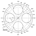
続いて、コントローラ90は、ステップS134において、上記8つの回転角度A(1)〜A(8)に基づいて、加工対象物OBのセット位置を計算する。加工対象物OBのセット位置は、図10に示すように、テーブル21に対する加工対象物OBの配置された回転角度により表される。加工対象物OBの配置された回転角度とは、テーブル21の中心(固定治具110の中心)である原点と各加工対象物OBの中心とを結ぶライン上を、レーザ光が照射しているときのテーブル21の回転角度C(1)〜C(4)である。この回転角度C(1)〜C(4)は次式のように算出される。
C(1)=(A(1)+A(2))/2
C(2)=(A(3)+A(4))/2
C(3)=(A(5)+A(6))/2
C(4)=(A(7)+A(8))/2
Subsequently, in step S134, the
C (1) = (A (1) + A (2)) / 2
C (2) = (A (3) + A (4)) / 2
C (3) = (A (5) + A (6)) / 2
C (4) = (A (7) + A (8)) / 2
この回転角度により、加工対象物OBのセット位置が求められるが、ここでは、更に、図10に示すように、エラーデータの存在を判定するための領域を定める回転角度B(1)〜B(8)を算出する。この回転角度B(1)〜B(8)は、テーブル21の中心から加工対象物OBに接する2本の接線上をレーザ光が照射しているときのテーブル21の回転角度である。回転角度B(1)〜B(8)は、次式のように算出される。
B(1)=C(1)−sin-1(rk/rc)
B(2)=C(1)+sin-1(rk/rc)
B(3)=C(2)−sin-1(rk/rc)
B(4)=C(2)+sin-1(rk/rc)
B(5)=C(3)−sin-1(rk/rc)
B(6)=C(3)+sin-1(rk/rc)
B(7)=C(4)−sin-1(rk/rc)
B(8)=C(4)+sin-1(rk/rc)
ここで、rcはテーブル21の中心(固定治具110の中心)から加工対象物OBの中心までの距離であり、rkは個々の加工対象物OBの半径である。
Based on this rotation angle, the set position of the workpiece OB is obtained. Here, however, as shown in FIG. 10, rotation angles B (1) to B (1) that define a region for determining the presence of error data. 8) is calculated. The rotation angles B (1) to B (8) are rotation angles of the table 21 when the laser light is radiated on two tangent lines in contact with the workpiece OB from the center of the table 21. The rotation angles B (1) to B (8) are calculated as follows.
B (1) = C (1) −sin −1 (rk / rc)
B (2) = C (1) + sin −1 (rk / rc)
B (3) = C (2) −sin −1 (rk / rc)
B (4) = C (2) + sin −1 (rk / rc)
B (5) = C (3) −sin −1 (rk / rc)
B (6) = C (3) + sin −1 (rk / rc)
B (7) = C (4) −sin −1 (rk / rc)
B (8) = C (4) + sin −1 (rk / rc)
Here, rc is the distance from the center of the table 21 (center of the fixing jig 110) to the center of the workpiece OB, and rk is the radius of each workpiece OB.
尚、上記の計算は、回転角度0のラインが加工対象物OB上にない場合であるので、上記計算を行う前に,A(2)−A(1)の値を算出して、この値が設定値より小さい場合には、回転角度0のラインが加工対象物OB上にあると判定する。この場合には、A(1)をA(8)とし、他のA(n)についても、nの値を1減算した値にしておいて、回転角度C(1)〜C(4)を計算すればよい。この回転角度C(1)〜C(4)は、各加工対象物OBごとのマーク形成目標位置の回転角度となる。
In addition, since the above calculation is a case where the line with the
コントローラ90は、このステップS134の加工対象物OBのセット位置の計算を行うと、ステップS136にてセット位置取得ルーチンを終了する。そして、レーザ加工ルーチンを開始する。第2実施形態のレーザ加工ルーチンは、その前半部分が第1実施形態のレーザ加工ルーチンと同一であるため、ここでは、第1実施形態と相違する後半部分について説明する。図11は、第2実施形態におけるレーザ加工ルーチンの後半部分を表すフローチャートであり、第1実施形態のレーザ加工ルーチンのステップS42〜ステップS82の処理に代えて行う処理を表す。
When the
コントローラ90は、上述したようにステップS10〜S40(図3A)において、加工対象物OBのレーザ加工、および、加工対象物OBの検査データである波高値データ、回転角度データ、半径位置データの取り込みを行うと、ステップS242において、エラーデータが存在するか否かを判断する。先のステップS40にて第2データ保存回路62、第3データ保存回路63からデータを取り込んだときに、回転角度データ、半径位置データが存在していた場合にはエラーデータが存在していると判定し、回転角度データ、半径位置データが存在していなかった場合にはエラーデータが存在していないと判定する。コントローラ90は、エラーデータが存在しないと判断した場合(S242:No)、ステップS244において、回転角度検出回路51に作動停止を指示する。これにより、回転角度検出回路51は、その作動を停止する。そして、ステップS246において、表示装置92にエラーが存在しなかったことを表示装置92に表示して本加工制御ルーチンを終了する。
As described above, the
一方、エラーデータが存在している場合には(S242:Yes)、コントローラ90は、その処理をステップS248に進めて、フィードモータ制御回路54に対して、マーク目標半径位置にまで移動するように指示する。このマーク目標半径位置は、円周上に配置された各加工対象物OBの外周と内接する円(図10に示す半径rdの円)の半径位置(最外周半径位置と呼ぶ)から所定距離aだけ内側となる位置に設定される。この距離aは微少値に設定されているため、マーク目標半径位置は、各加工対象物OBの最外周部となる。フィードモータ制御回路54は、コントローラ90からマーク目標半径位置が指示されると、半径位置検出回路52によって検出された半径位置を入力しながらフィードモータ23の回転を制御して、加工用レーザ光の照射位置がマーク目標半径位置に一致するまでテーブル21を移動する。
On the other hand, if error data exists (S242: Yes), the
続いて、コントローラ90は、ステップS250において、変数nの値を「1」に設定する。続いて、コントローラ90は、ステップS252において、スピンドルモータ制御回路53に対して予め設定した超低速回転での回転開始を指示する。スピンドルモータ制御回路53は、この指示に基づいて超低速回転にてスピンドルモータ22を回転駆動する。
Subsequently, in step S250, the
続いて、コントローラ90は、ステップS254において、回転角度B(2n−1)〜B(2n)の範囲においてエラーデータが存在しているか否かを判断する。加工対象物OBは、テーブル21上の回転角度B(2n−1)〜B(2n)の範囲に存在するため、その範囲において異常部が存在しているか否かを判断すればよい。以下、回転角度B(2n−1)〜B(2n)の範囲を検査対象角度範囲と呼ぶ。コントローラ90は、ステップS40にて取り込んだ回転角度データの中に回転角度B(2n−1)〜B(2n)の範囲内のものがあるか判定する。
Subsequently, in step S254, the
コントローラ90は、ステップS254において「No」、つまり、エラーデータが存在しないと判断した場合には、ステップS256において、変数nの値を「1」だけインクリメントする。そして、ステップS258において、変数nの値が「5」であるか否かを判断し、n=5でない場合には、その処理をステップS254に戻す。
If the
一方、ステップS254において、エラーデータが検査対象角度範囲に存在すると判断した場合には、ステップS260において、回転角度検出回路51によって検出した回転角度を取り込む。そして、ステップS262において、その検出した回転角度から回転角度C(n)を減算した値の絶対値が、予め設定した設定値A以下になったか否かを判断する。この設定値Aは、予め設定した値であって、非常に小さな値に設定されている。従って、このステップS262においては、回転角度検出回路51によって検出した回転角度が回転角度C(n)に実質的に一致したか否かを判断する。
On the other hand, if it is determined in step S254 that the error data exists in the inspection target angle range, the rotation angle detected by the rotation
コントローラ90は、テーブル21の回転角度と回転角度C(n)との差の絶対値が設定値A以下になるまでステップS260,S262の処理を繰り返す。そして、テーブル21の回転角度と回転角度C(n)との差の絶対値が設定値A以下になると、ステップS264において、スピンドルモータ制御回路53に対して回転停止を指示する。スピンドルモータ制御回路53は、この指示によりスピンドルモータ22を停止させる。スピンドルモータ22は、超低速で回転しているため瞬時に停止する。従って、テーブル21は、その回転角度が実質的に回転角度C(n)になったところで停止することになる。尚、設定値Aは、回転角度検知から停止までの僅かな遅れや分解能を考慮した値であって、テーブル21を実質的に回転角度C(n)で停止できればゼロに設定してもよい。
The
続いて、コントローラ90は、ステップS266において、第1レーザ駆動回路71に対して非加工用レーザ光照射の開始を指示し、ステップS268において、フォーカスサーボ回路76に作動開始を指示する。続いて、ステップS270において、第1レーザ駆動回路71に対して加工用レーザ光の照射開始を指示する。これにより、第1レーザ駆動回路71は、第1レーザ光源31に出力していた駆動信号を、非加工レベルから加工レベルに切り替える。このステップS266,S268,S270の処理は、ステップS58,S60,S62と同じである。
Subsequently, the
続いて、コントローラ90は、ステップS272において、フィードモータ制御回路54に対して、移動速度Fにて半径方向(径方向外側)への移動開始を指示する。これにより、フィードモータ制御回路54は、エンコーダ23aからの回転検出信号からテーブル21の半径方向の移動速度を計算して、計算された移動速度がコントローラ90によって指定された移動速度Fと等しくなるようにフィードモータ23の回転制御を開始する。
Subsequently, in step S272, the
続いて、コントローラ90は、ステップS274において、半径位置検出回路52から半径位置データを取り込み、ステップS276において、検出された半径位置が加工対象物OBの最外周半径rdと一致するか否かを判断する。半径位置が加工対象物OBの最外周半径rdと一致するまで、ステップS274,S276の処理が繰り返される。この期間においては、テーブル21が半径方向(径方向外側)に移動するとともに、加工用レーザ光がn番目の加工対象物OBに照射されることになる。従って、n番目の加工対象物OBのマーク目標半径位置から半径方向に加工用レーザ光の光スポット位置が移動していく。つまり、マーク目標半径位置から半径方向に向かってレーザ加工が直線状に施されていく。
Subsequently, the
コントローラ90は、ステップS276において、半径位置が加工対象物OBの最外周半径rdと一致したと判断すると、ステップS278において、フォーカスサーボ回路76にフォーカスサーボ制御の停止を指示する。続いて、ステップS280において、第1レーザ駆動回路71に対して加工用レーザ光の照射停止を指示する。これにより、第1レーザ駆動回路71は、第1レーザ光源31に出力していた駆動信号を停止する。こうして、n番目の加工対象物OBへのマーク付けが終了する。加工対象物OBのマークは、マーク目標半径位置から加工対象物OBの外周端まで直線状に形成される。
If the
こうして、n番目の加工対象物OBのマーク付けが完了すると、コントローラ90は、ステップS281において、フィードモータ制御回路54に対してマーク目標半径位置にまで移動するように指示した後、その処理をステップS256に戻す。従って、コントローラ90は、変数nの値を「1」だけインクリメントする。変数nの値が「5」に達しないうちは、ステップS254において、次の加工対象物OBの検査対象角度範囲にエラーデータが存在するか否かの判断が行われる。そして、検査対象角度範囲にエラーデータが存在すれば、上述したステップS260〜S281の処理により、n番目の加工対象物OBの外周部にレーザ加工によりマーク付けを行う。検査対象角度範囲にエラーデータが存在しなければ、変数nの値を「1」だけインクリメントして、次の加工対象物OBの検査対象角度範囲にエラーデータが存在するか否かを判断する。
When the marking of the n-th workpiece OB is completed in this way, the
コントローラ90は、こうした処理を繰り返し、ステップS258において、変数nの値が「5」に達したと判断すると、その処理をステップS282に進め、回転角度検出回路51に作動停止を指示する。これにより、回転角度検出回路51は、その作動を停止する。この時点においては、全ての加工対象物OBのうち異常部が存在していると判断したものについては、外周部にマークが形成されている。最終的には、このマークを基準に使って加工対象物OBごとにエラー箇所を定めるが、ステップS40において取り込んだデータのうち回転角度データ、半径位置データは、テーブル21の中心点を基準として得られたデータであるため、そのままでは各加工対象物OBのマークを基準としてエラー箇所を定めることができない。
When the
そこで、コントローラ90は、ステップS284において、ステップS76,S78と同様にエラー開始点(r,θ’)を計算した後、各加工対象物OBにおけるエラー箇所を、各加工対象物OBの中心点を原点とした座標値として算出する。例えば、図12に示すように、テーブル21上の4つの加工対象物OBごとに、その中心点を原点としたX1−Y1座標,X2−Y2座標,X3−Y3座標,X4−Y4座標を設定する。この場合、テーブル21の中心点と各加工対象物OBの中心点とを結んだ直線をY1軸,Y2軸,Y3軸,Y4軸とし、そのY1軸,Y2軸,Y3軸,Y4軸に直交し各加工対象物OBの中心点を通る直線をX1軸,X2軸,X3軸,X4軸とする。Y1軸,Y2軸,Y3軸,Y4軸は、マークを通る軸でもある。
Therefore, after calculating the error start point (r, θ ′) in step S284 in the same manner as in steps S76 and S78, the
先のステップS40において取り込んだ波高値データ、回転角度データ、半径位置データから、上述したようにエラー検出点(r,θ)とエラー開始点(r,θ’)とが求められる。従って、この2つの点を結ぶ円弧をテーブル21のX−Y座標の点の集合として表すことができる。そして、テーブル21のX−Y座標の点の集合として表したエラー箇所を示すデータを各加工対象物OBにおけるX1−Y1座標,X2−Y2座標,X3−Y3座標,X4−Y4座標における座標値に変換する。例えば、テーブル21のX−Y座標における点の位置を(x、y)とした場合、4つの加工対象物OBのX1−Y1座標,X2−Y2座標,X3−Y3座標,X4−Y4座標における点(x1,y1),点(x2,y2),点(x3,y3),点(x4,y4)は、次式にて計算することができる。

続いて、コントローラ90は、ステップS286において、上記計算して得られたエラー箇所の座標値(各加工対象物OBにおける座標値)をエラー箇所情報として、加工対象物OBのシリアルナンバーと対応させてハードディスク等の記憶装置に記憶する。続いて、コントローラ90は、ステップS288において、エラー箇所情報を用いて表示装置92に加工対象物OBにおけるエラー箇所(異常部の領域)を表示する。この場合、第1実施形態と同様に、加工対象物OBに形成したマークの位置も合わせて表示するが、4枚の加工対象物OBのエラー箇所を同時に表示しても良いし、図5に示すように、1枚ずつ表示するようにしてもよい。
Subsequently, in step S286, the
コントローラ90は、表示装置92によりエラー箇所の表示を所定時間行うと、ステップS290にて本レーザ加工ルーチンを終了する。各加工対象物OBのエラー箇所情報は、マークの形成位置をY軸とした座標値として記憶装置に記憶される。このため、加工対象物OBをテーブル21から取り出した後においても、加工対象物OBのエラー箇所を特定することができる。従って、上述したレーザ加工ルーチンに、ステップS246やステップS288の表示処理を組み込まないようにしてもよい。
When the
以上説明した第2実施形態のレーザ加工装置2によれば、第1実施形態の作用効果に加えて、複数の加工対象物OBに対して同時にレーザ加工および異常検査を行うことができるため、一層、生産効率を向上させることができるという効果を奏する。
According to the
以上、本発明の実施形態について説明したが、本発明の実施にあたっては、上記実施形態に限定されるものではなく、本発明の目的を逸脱しない限りにおいて種々の変形も可能である。 The embodiments of the present invention have been described above. However, the present invention is not limited to the above-described embodiments, and various modifications can be made without departing from the object of the present invention.
例えば、本実施形態においては、加工用レーザ光の照射により加工対象物OBの外周部にマークを形成したが、予め加工対象物OBにマーク、あるいは、それに代わる模様が形成されている場合や、加工対象物OBの形状が加工対象物OBのエラー箇所を特定できる形状となっている場合には、マークを形成する工程を省略することができる。この場合、第1実施形態においては、テーブル21に回転角度0(または設定された回転角度)となるときのレーザ光照射位置にラインを表示しておき、このラインにマーク等の目印を合わせるようにして加工対象物OBをテーブル21にセットすればよい。また、第2実施形態においては、テーブル21の中心点と加工対象物OBの中心点とを通るラインをテーブル21に表示しておき、このラインにマーク等の目印を合わせるようにして各加工対象物OBをテーブル21にセットすればよい。 For example, in the present embodiment, a mark is formed on the outer peripheral portion of the processing object OB by irradiation with the processing laser light. However, when a mark or a pattern in place of the mark is formed on the processing object OB in advance, When the shape of the workpiece OB is a shape that can identify an error location of the workpiece OB, the step of forming a mark can be omitted. In this case, in the first embodiment, a line is displayed on the table 21 at the laser beam irradiation position when the rotation angle is 0 (or a set rotation angle), and a mark such as a mark is aligned with this line. Then, the processing object OB may be set on the table 21. In the second embodiment, a line passing through the center point of the table 21 and the center point of the processing object OB is displayed on the table 21, and each processing object is set so that a mark such as a mark is aligned with this line. The object OB may be set on the table 21.
また、本実施形態においては、加工対象物OBの表面にマークを形成するにあたって、加工対象物OBを回転させずに半径方向に送りながらレーザ光を照射することで加工対象物OBの外周部に直線状のマークを形成したが、加工対象物OBのエラー箇所を定めることができるものであれば、どのような方法でマークを形成してもよい。例えば、加工対象物OBを移動させずにレーザ光を照射して点状のマークを形成してもよい。また、加工対象物OBを半径方向には送らずに微少角度だけ回転させながらレーザ光を照射して円弧状のマークを形成するようにしてもよい。また、マークの形成は、レーザ加工で行う必要もなく、例えば、インク等の塗料を塗布するようにしてもよい。 In the present embodiment, when forming a mark on the surface of the workpiece OB, the outer circumference of the workpiece OB is irradiated by irradiating the laser beam while feeding the workpiece OB in the radial direction without rotating. Although the linear mark is formed, the mark may be formed by any method as long as the error portion of the workpiece OB can be determined. For example, a point mark may be formed by irradiating a laser beam without moving the workpiece OB. Alternatively, the workpiece OB may be irradiated with laser light while being rotated by a minute angle without being sent in the radial direction to form an arc-shaped mark. Further, the mark need not be formed by laser processing. For example, a paint such as ink may be applied.
また、本実施形態においては、加工対象物OBの表面にマークを形成したが、必ずしも加工対象物OBの表面に形成する必要はない。例えば、加工対象物OBの外周端の一部をカットして、そのカットした部分をマークとして使用することもできる。 In the present embodiment, the mark is formed on the surface of the workpiece OB. However, it is not always necessary to form the mark on the surface of the workpiece OB. For example, a part of the outer peripheral end of the workpiece OB can be cut and the cut part can be used as a mark.
また、本実施形態においては、加工対象物OBをセットするセット部として円盤状のテーブル21を用いているが、図13に示すように、ドラム状の固定治具121をセット部として備えたレーザ加工装置3であってもよい。このレーザ加工装置3は、固定治具121を回転可能に備えた移動ステージ140と、移動ステージ140に固定され固定治具121を回転させるスピンドルモータ122と、移動ステージ140を固定治具121の軸線方向に移動可能に支持するステージガイド141と、ステージガイド141に設けられるねじ送り機構142と、ねじ送り機構142を介して移動ステージ140を移動させるフィードモータ123と、ステージガイド141から立設されたヘッド支持フレーム143に固定される加工ヘッド130とを備えている。スピンドルモータ122、フィードモータ123、加工ヘッド130は、上記第1実施形態のスピンドルモータ22、フィードモータ23、加工ヘッド30に相当するものである。
In this embodiment, the disk-shaped table 21 is used as a set part for setting the workpiece OB. However, as shown in FIG. 13, a laser provided with a drum-shaped
このレーザ加工装置3においては、固定治具121にシート状の加工対象物OB’をセットし、固定治具121を中心軸周りに回転させながら軸線方向に送ることで、加工ヘッド130から照射されたレーザ光(加工用レーザ光および検査用レーザ光)の照射位置を加工対象物OB’の表面全体にわたって移動させる構成を採用している。このレーザ加工装置3において加工対象物OB’の異常を検査する場合、エラー検出したときの送り量(移動ステージの原点からの移動量)をr、固定治具121の基準回転位置に対する回転角度をθ、エラー長さL、加工対象物OB’の周方向の長さ(=固定治具121の周長)をHとすると、加工対象物OB’を平面上に展開したときのエラー検出点の座標は、(r,H・θ/2π)として表され、エラー開始点の座標は、(r,H・θ’/2π)として表される。ここで、θ’は、θ’=θ−L/(H/2π)である。
In this
また、このレーザ加工装置3を使って加工対象物OB’にマークを形成する場合には、固定治具121が回転角度0(あるいは予め設定した角度)となるときに加工対象物OB’の移動方向端部に加工用レーザ光を照射してマークを形成してもよいが、固定治具121が回転角度0(あるいは予め設定した角度)となるときにレーザ光が照射されるラインを固定治具121の表面に表示しておき、このラインにシート状の加工対象物OB’の縁を合わせてセットするようにすれば、加工対象物OB’にマークを形成する工程を省略することができる。
Further, when a mark is formed on the workpiece OB ′ using the
また、本実施形態においては、加工対象物OBに照射したレーザ光の反射光の強度に基づいて異常を検出したが、加工対象物OBが光の透過率が大きい場合には、テーブル21も光の透過率の大きいものを用いることにより、加工対象物OBとテーブル21とを透過した透過光の強度に基づいて異常を検出することができる。この場合、加工ヘッドには、検査用レーザ光を照射する照射部と、透過光を受光する受光部とをテーブル21を挟んで向かい合うように設ける。これによっても、上述した実施形態と同様の効果を奏することができる。 In the present embodiment, an abnormality is detected based on the intensity of the reflected light of the laser light applied to the workpiece OB. However, when the workpiece OB has a high light transmittance, the table 21 is also light. By using the one having a large transmittance, it is possible to detect an abnormality based on the intensity of the transmitted light transmitted through the workpiece OB and the table 21. In this case, the processing head is provided with an irradiation unit for irradiating the inspection laser beam and a light receiving unit for receiving the transmitted light so as to face each other with the table 21 interposed therebetween. Also by this, the same effect as the above-described embodiment can be obtained.
また、本実施形態においては、加工ヘッド30とテーブル21との相対位置を変更するにあたって、テーブル21をその半径方向に移動させる構成を採用しているが、加工ヘッド30をテーブル21の半径方向に移動させる構成であってもよい。また、テーブル21と加工ヘッド30との両方を関連させて移動させるようにすることもできる。また、ドラム状の固定治具121を設けた図13に示すレーザ加工装置3の場合には、固定治具121を軸線方向に移動させずに、加工ヘッド130を固定治具121の軸線方向に移動させる構成であってもよい。これによっても、上述した実施形態と同様の効果を奏することができる。
In this embodiment, when changing the relative position between the machining
また、本実施形態においては、加工用レーザ光の照射により加工対象物OBの表面をレーザ加工するが、このレーザ加工は、加工対象物OBにピットや連続した溝を直接形成する加工だけでなく、後工程において現像液の作用によりピットや連続した溝が形成される反応跡を形成するものでもよい。 In the present embodiment, the surface of the workpiece OB is laser-processed by the irradiation of the processing laser beam. This laser processing is not limited to the processing of directly forming pits and continuous grooves on the workpiece OB. In the subsequent process, a reaction trace in which pits or continuous grooves are formed by the action of the developer may be used.
また、本実施形態においては、検査用レーザ光の反射光強度を第2フォトディテクタ45により検出したが、これに代えて、複数の受光領域に分割されたフォトディテクタを用いて各受光領域ごとに反射光強度を検出し、この検出した反射光強度を使った演算式により得られる演算結果に基づいて異常検出を行うようにしてもよい。例えば、検査用レーザ光の反射光を受光するフォトディテクタとして、本実施形態の第1フォトディテクタ39と同様な4分割受光素子にて構成されるフォトディテクタを使用する。そして、時計回りに配置された4つの受光領域(A,B,C,D)に入射した反射光の強度(a,b,c,d)を用いて、(a+d)−(b+c)を演算し、この演算結果である演算値と予め設定した基準値(あるいは基準範囲)とを比較することにより、異常箇所を検出することもできる。この場合、異常箇所においては、S字状に信号が変化する。従って、演算値が、上下に設けた基準値を1回ずつ基準範囲外から基準範囲内に向かってクロスしたときに検出信号を出力するようにするとよい。これによっても、上述した実施形態と同様の効果を奏する。
In the present embodiment, the reflected light intensity of the inspection laser beam is detected by the
また、この4分割フォトディテクタの前にシリンドリカルレンズを配置して、(a+c)−(b+d)を演算し、即ちフォーカスエラー信号を作成し、この演算結果である演算値と予め設定した基準値(あるいは基準範囲)とを比較することにより、異常箇所を検出することもできる。これによっても、上述した実施形態と同様の効果を奏する。 In addition, a cylindrical lens is arranged in front of this quadrant photodetector, and (a + c) − (b + d) is calculated, that is, a focus error signal is generated, and the calculated value and the preset reference value (or It is also possible to detect an abnormal point by comparing with the (reference range). This also has the same effect as the above-described embodiment.
また、微分回路を設け、検査用レーザ光の反射光の強度を時間で微分した値と、基準値(あるいは基準範囲)とを比較することにより異常箇所を検出することもできる。この場合も、異常箇所においては、反射光信号を微分した微分値がS字状に変化するため、微分値が、上下に設けた基準値を1回ずつ基準範囲外から基準範囲内に向かってクロスしたときに検出信号を出力するようにするとよい。これによっても、上述した実施形態と同様の効果を奏する。 Further, an abnormal portion can be detected by providing a differentiating circuit and comparing a value obtained by differentiating the intensity of the reflected light of the inspection laser light with a reference value (or a reference range). Also in this case, since the differential value obtained by differentiating the reflected light signal changes in an S shape at the abnormal location, the differential value is changed from the reference range to the reference range from outside the reference range one by one. It is preferable to output a detection signal when crossing. This also has the same effect as the above-described embodiment.
尚、本実施形態におけるテーブル21,固定治具121が本発明のセット部に相当し、本実施形態におけるスピンドルモータ22,122およびスピンドルモータ制御回路53が回転手段に相当し、本実施形態における加工ヘッド30,130が本発明の加工ヘッドに相当し、本実施形態の第1レーザ駆動回路71,第2レーザ駆動回路72が本発明の第1レーザ駆動回路,第2レーザ駆動回路に相当し、本実施形態のフィードモータ23,123およびフィードモータ制御回路54が本発明の送り手段に相当する。また、本実施形態のレーザ加工ルーチンのステップS12〜S36を実施するコントローラ90の機能部が本発明の加工制御手段に相当し、ステップS20,S34を実施するコントローラ90の機能部が本発明の検査用レーザ光照射制御手段に相当する。また、本実施形態の第2フォトディテクタ45が本発明の光検出手段に相当し、本実施形態のエラー判定回路83が本発明の異常検出手段に相当する。また、本実施形態の回転角度検出回路51およびエンコーダ22aが本発明の回転角度検出手段に相当し、本実施形態の半径位置検出回路52およびエンコーダ23aが本発明の送り位置検出手段に相当する。また、本実施形態の第1データ保存回路61が光履歴記憶手段に相当し、本実施形態のレーザ加工ルーチンのステップS40を実施するコントローラ90の機能部が本発明の異常検出情報取得手段に相当し、ステップS76〜S80あるいはステップS284〜S288を実施するコントローラ90の機能部が本発明の異常箇所情報作成手段に相当する。また、本実施形態のレーザ加工ルーチンのステップS48〜S56あるいはS248〜S254,S260〜264を実施するコントローラ90の機能部が本発明のマーク位置移動制御手段に相当し、ステップS58〜S72あるいはS266〜S280を実施するコントローラ90の機能部が本発明のマーク形成手段に相当する。また、本実施形態のセット位置取得ルーチンを実施するコントローラ90の機能部が本発明の固定位置検出手段に相当する。また、本実施形態のレーザ加工ルーチンのステップS284を実施するコントローラ90の機能部が本発明の異常箇所情報変換手段に相当する。また、本実施形態のセット位置取得ルーチンのステップS134を実施するコントローラ90の機能部が本発明のマーク目標位置演算手段に相当する。また、本実施形態のレーザ加工ルーチンのステップS254〜S258を実施するコントローラ90の機能部が本発明の繰り返し手段に相当する。
The table 21 and the fixing
また、本実施形態のレーザ加工ルーチンのステップS12〜S36が本発明の照射ステップに相当し、ステップS26が本発明の光検出ステップと異常検出ステップに相当する。また、本実施形態のレーザ加工ルーチンのステップS40が本発明の異常検出情報取得ステップに相当し、ステップS76〜S80あるいはステップS284〜S288が本発明の異常箇所情報作成ステップに相当する。また、本実施形態のレーザ加工ルーチンのステップS48〜S56あるいはS248〜S254,S260〜264が本発明のマーク位置移動ステップに相当し、ステップS58〜S72あるいはS266〜S280が本発明のマーク形成ステップに相当する。また、第2実施形態のレーザ加工装置においてレーザ加工前に作業者が加工対象物OBを固定治具121に固定する処理が本発明の固定ステップに相当する。また、本実施形態のセット位置取得ルーチンが本発明の固定位置検出ステップに相当する。また、本実施形態のレーザ加工ルーチンのステップS284が本発明の異常箇所情報変換ステップに相当する。
Further, steps S12 to S36 of the laser processing routine of the present embodiment correspond to the irradiation step of the present invention, and step S26 corresponds to the light detection step and the abnormality detection step of the present invention. Further, step S40 of the laser processing routine of the present embodiment corresponds to the abnormality detection information acquisition step of the present invention, and steps S76 to S80 or steps S284 to S288 correspond to the abnormal portion information creation step of the present invention. Further, steps S48 to S56 or S248 to S254 and S260 to 264 of the laser processing routine of this embodiment correspond to the mark position moving step of the present invention, and steps S58 to S72 or S266 to S280 are the mark forming step of the present invention. Equivalent to. In the laser processing apparatus of the second embodiment, the process in which the operator fixes the workpiece OB to the fixing
1,2,3…レーザ加工装置、21…テーブル、22,122…スピンドルモータ、22a…エンコーダ、23,123…フィードモータ、23a…エンコーダ、30,130…加工ヘッド、31…第1レーザ光源、39…第1フォトディテクタ、41…第2レーザ光源、45…第2フォトディテクタ、51…回転角度検出回路、52…半径位置検出回路、53…スピンドルモータ制御回路、54…フィードモータ制御回路、61…第1データ保存回路、62…第2データ保存回路、63…第3データ保存回路、71…第1レーザ駆動回路、72…第2レーザ駆動回路、73…発光信号供給回路、83…エラー判定回路、85…エッジ検出回路、90…コントローラ、91…入力装置、92…表示装置、110,121…固定治具、140…移動ステージ、141…ステージガイド、OB,OB’…加工対象物。
DESCRIPTION OF
Claims (16)
前記セット部を回転させる回転手段と、
第1レーザ光源と第2レーザ光源とを有し、両光源から出射されたレーザ光を前記加工対象物に向けて照射する加工ヘッドと、
前記第1レーザ光源に駆動信号を出力して前記加工対象物の表面をレーザ加工可能な強度の加工用レーザ光を前記第1レーザ光源から出射させる第1レーザ駆動回路と、
前記第2レーザ光源に駆動信号を出力して前記加工対象物の表面がレーザ加工されない強度の検査用レーザ光を前記第2レーザ光源から出射させる第2レーザ駆動回路と、
前記第1レーザ光源から出射された加工用レーザ光の照射位置が、前記加工対象物の表面上を、前記セット部の回転により形成される照射移動軌跡に対して直交する方向に移動するように、前記セット部と前記加工ヘッドとの相対位置を変更する送り手段と、
前記回転手段と前記送り手段との作動を制御しつつ、前記第1レーザ駆動回路を作動させて前記加工対象物の表面に加工用レーザ光を照射することにより、前記加工対象物の表面をレーザ加工する加工制御手段と、
前記加工制御手段により前記加工対象物の表面をレーザ加工しているときに、前記第2レーザ駆動回路を作動させて前記加工対象物の表面に検査用レーザ光を照射する検査用レーザ光照射制御手段と、
前記加工対象物の表面に照射した前記検査用レーザ光の反射光または透過光の強度を検出する光検出手段と、
前記光検出手段により検出した反射光または透過光の強度に基づいて、前記加工対象物における異常を検出する異常検出手段と
を備えたレーザ加工装置。 A set part for setting a workpiece;
Rotating means for rotating the set unit;
A processing head having a first laser light source and a second laser light source, and irradiating the processing object with laser light emitted from both light sources;
A first laser driving circuit for outputting a driving signal to the first laser light source to emit a processing laser beam having an intensity capable of laser processing the surface of the workpiece from the first laser light source;
A second laser driving circuit for outputting a driving signal to the second laser light source to emit an inspection laser beam having an intensity at which the surface of the workpiece is not laser processed, from the second laser light source;
An irradiation position of the processing laser light emitted from the first laser light source moves on the surface of the processing object in a direction orthogonal to an irradiation movement locus formed by rotation of the set unit. A feeding means for changing a relative position between the set unit and the processing head;
While controlling the operation of the rotating means and the feeding means, the first laser driving circuit is operated to irradiate the surface of the object to be processed with laser light for processing, thereby laser-treating the surface of the object to be processed. Processing control means for processing;
Inspection laser light irradiation control for operating the second laser drive circuit to irradiate the surface of the processing object with the inspection laser light when the surface of the processing object is laser processed by the processing control means. Means,
A light detecting means for detecting the intensity of reflected or transmitted light of the inspection laser light irradiated on the surface of the workpiece;
A laser processing apparatus comprising: an abnormality detection unit that detects an abnormality in the workpiece based on the intensity of reflected light or transmitted light detected by the light detection unit.
前記送り手段による変更される前記セット部と前記加工ヘッドとの相対位置を送り位置として検出する送り位置検出手段と、
前記光検出手段により検出した前記反射光または透過光の強度の履歴を記憶する光履歴記憶手段と、
前記異常検出手段により前記加工対象物における異常が検出されたときの、前記回転角度検出手段により検出される回転角度と、前記送り位置検出手段により検出される送り位置と、前記光履歴記憶手段により記憶した反射光または透過光の強度の履歴とを異常検出情報として取得する異常検出情報取得手段と、
前記異常検出情報取得手段により取得した異常検出情報に基づいて、前記加工対象物の異常箇所を表す異常箇所情報を作成する異常箇所情報作成手段と
を備えたことを特徴とする請求項1ないし請求項3の何れか一項記載のレーザ加工装置。 A rotation angle detection means for detecting a rotation angle of the set portion rotated by the rotation means;
A feed position detecting means for detecting a relative position between the set portion changed by the feed means and the machining head as a feed position;
A light history storage means for storing a history of the intensity of the reflected or transmitted light detected by the light detection means;
The rotation angle detected by the rotation angle detection means when the abnormality in the workpiece is detected by the abnormality detection means, the feed position detected by the feed position detection means, and the light history storage means Abnormality detection information acquisition means for acquiring, as abnormality detection information, the history of the intensity of the reflected light or transmitted light stored,
The abnormality location information creating means for creating the abnormal location information representing the abnormal location of the workpiece based on the abnormality detection information acquired by the abnormality detection information acquisition device. Item 4. The laser processing apparatus according to any one of Items 3 to 3.
前記検出した反射光または透過光の強度が、予め設定した異常を判定するための閾値となる基準強度を境界として正常値側から異常値側の範囲に入り、その後、予め設定した異常判定用基準時間以上経過した後に、正常値側の範囲に戻った時に異常検出信号を出力するものであり、
前記異常検出情報取得手段は、
前記異常検出信号が出力されたときの前記回転角度検出手段により検出される回転角度と前記送り位置検出手段により検出される送り位置とを異常検出点情報として取得するとともに、前記異常検出信号が出力される直前の前記光履歴記憶手段に記憶されている反射光または透過光の強度の履歴を取得するものであり、
前記異常箇所情報作成手段は、
前記光履歴記憶手段に記憶されている反射光または透過光の強度が前記異常値側の範囲に入っている連続時間に基づいて前記加工対象物の回転方向における異常範囲長を計算し、その異常範囲長と前記異常検出点情報とから前記異常箇所情報を作成すること
を特徴とする請求項4記載のレーザ加工装置。 The abnormality detection means includes
The intensity of the detected reflected light or transmitted light enters a range from the normal value side to the abnormal value side with a reference intensity serving as a threshold for determining a preset abnormality, and then a preset abnormality determination reference An error detection signal is output when it returns to the normal value range after a lapse of time.
The abnormality detection information acquisition means includes
The rotation angle detected by the rotation angle detection means when the abnormality detection signal is output and the feed position detected by the feed position detection means are acquired as abnormality detection point information, and the abnormality detection signal is output. A history of the intensity of the reflected light or transmitted light stored in the light history storage means immediately before being obtained,
The abnormal part information creating means includes
An abnormal range length in the rotation direction of the workpiece is calculated based on a continuous time in which the intensity of reflected light or transmitted light stored in the light history storage means is in the range on the abnormal value side, and the abnormality The laser processing apparatus according to claim 4, wherein the abnormal part information is created from a range length and the abnormality detection point information.
前記第1レーザ駆動回路を作動させて、前記加工対象物のマーク形成目標位置に前記加工用レーザ光を照射し、前記加工対象物のマーク形成目標位置にマークを形成するマーク形成手段と
を備えたことを特徴とする請求項4または5記載のレーザ加工装置。 Based on the feed position detected by the feed position detection means and the rotation angle detected by the rotation angle detection means, the irradiation position of the processing laser light is an outer peripheral portion of the processing object, and a set rotation angle Mark position movement control means for driving and controlling the feed means and the rotation means so as to be a mark formation target position
Mark forming means for activating the first laser drive circuit to irradiate the mark forming target position of the workpiece with the processing laser beam and forming a mark at the mark forming target position of the workpiece; The laser processing apparatus according to claim 4 or 5, wherein
前記複数の加工対象物の前記セット部に対する固定位置を検出する固定位置検出手段と、
前記固定位置検出手段により検出されたそれぞれの加工対象物の固定位置に基づき、前記異常箇所情報作成手段により作成された異常箇所情報をそれぞれの加工対象物における座標に基づいた異常箇所情報に変換する異常箇所情報変換手段と
を備えたことを特徴とする請求項4または5記載のレーザ加工装置。 The set part includes a fixing jig for fixing a plurality of workpieces having the same shape on the same circumference around the rotation axis of the set part,
Fixed position detection means for detecting fixed positions of the plurality of workpieces with respect to the set unit;
Based on the fixed position of each processing object detected by the fixed position detection means, the abnormal location information created by the abnormal location information creation means is converted into abnormal location information based on the coordinates of each processing object. The laser processing apparatus according to claim 4, further comprising: an abnormal part information conversion unit.
前記加工用レーザ光の照射位置が1つの加工対象物のマーク形成目標位置となるように、前記送り手段と前記回転手段とを駆動制御するマーク位置移動制御手段と、
前記第1レーザ駆動回路を作動させて、前記1つの加工対象物のマーク形成目標位置に前記加工用レーザ光を照射し、前記加工対象物のマーク形成目標位置にマークを形成するマーク形成手段と、
前記マーク位置移動制御手段による前記加工用レーザ光の前記マーク形成目標位置への移動と、前記マーク形成手段による前記加工対象物のマーク形成目標位置への前記加工用レーザ光の照射とを、前記各加工対象物のそれぞれに対して行うように、前記マーク位置移動制御手段と前記マーク形成手段とに指示する繰り返し手段と
を備えたことを特徴とする請求項7記載のレーザ加工装置。 Mark target position calculation means for calculating, as a mark formation target position, a position on a straight line connecting the center of each processing object and the center of rotation of the set part at the outer periphery of each processing object;
Mark position movement control means for drivingly controlling the feeding means and the rotating means so that the irradiation position of the processing laser light becomes a mark formation target position of one processing object;
Mark forming means for activating the first laser drive circuit to irradiate the mark forming target position of the one object to be processed with the processing laser beam and forming a mark at the mark forming target position of the object to be processed; ,
The movement of the processing laser light to the mark formation target position by the mark position movement control means, and the irradiation of the processing laser light to the mark formation target position of the processing object by the mark formation means, The laser processing apparatus according to claim 7, further comprising: a repetitive unit that instructs the mark position movement control unit and the mark forming unit to perform each of the processing objects.
前記セット部を回転させる回転手段と、
前記加工対象物にレーザ光を照射する加工ヘッドと、
前記レーザ光の照射位置が、前記加工対象物の表面上を、前記セット部の回転により形成される照射移動軌跡に対して直交する方向に移動するように、前記セット部と前記加工ヘッドとの相対位置を変更する送り手段とを備えたレーザ加工装置に適用され、
前記セット部に前記加工対象物をセットした状態で、前記回転手段と送り手段との作動を制御しながら、前記加工ヘッドから前記加工対象物の表面をレーザ加工可能な強度の加工用レーザ光と、前記加工対象物の表面がレーザ加工されない強度の検査用レーザ光とを同時に前記加工対象物に照射する照射ステップと、
前記加工対象物の表面に照射した前記検査用レーザ光の反射光または透過光の強度を検出する光検出ステップと、
前記検出した反射光または透過光の強度に基づいて、前記加工対象物における異常を検出する異常検出ステップと
を含むことを特徴とするレーザ加工方法。 A set part for setting a workpiece;
Rotating means for rotating the set unit;
A machining head for irradiating the workpiece with laser light;
The set portion and the processing head are arranged such that the irradiation position of the laser light moves on the surface of the processing object in a direction orthogonal to an irradiation movement locus formed by rotation of the setting portion. Applied to a laser processing apparatus having a feeding means for changing the relative position;
With the processing object set in the set part, while controlling the operation of the rotating means and the feeding means, the processing laser beam having a strength capable of laser processing the surface of the processing object from the processing head; Irradiating the processing object simultaneously with an inspection laser beam having a strength at which the surface of the processing object is not laser processed;
A light detection step of detecting the intensity of reflected or transmitted light of the inspection laser light irradiated on the surface of the workpiece;
An abnormality detection step of detecting an abnormality in the object to be processed based on the detected intensity of the reflected light or transmitted light.
前異常検出情報取得ステップにより取得した異常検出情報に基づいて、加工対象物の異常箇所を表す異常箇所情報を作成する異常箇所情報作成ステップと
を含むことを特徴とする請求項11記載のレーザ加工方法。 When an abnormality is detected in the object to be processed by the abnormality detection step, the rotation angle of the set unit, the feed position representing the relative position between the set unit and the processing head, and the reflection of the inspection laser light An abnormality detection information acquisition step for acquiring a history of the intensity of light or transmitted light as abnormality detection information;
The laser processing according to claim 11, further comprising: an abnormal location information creating step of creating abnormal location information representing an abnormal location of the workpiece based on the abnormality detection information acquired in the previous abnormality detection information acquisition step. Method.
前記検出した反射光または透過光の強度が、予め設定した異常を判定するための閾値となる基準強度を境界として正常値側から異常値側の範囲に入り、その後、予め設定した異常判定用基準時間以上経過した後に、正常値側の範囲に戻った時に異常検出信号を出力するものであり、
前記異常情報取得ステップは、
前記異常検出信号が出力されたときの前記回転角度と前記送り位置とを異常検出点情報として取得するとともに、前記異常検出信号が出力される直前の反射光または透過光の強度の履歴を取得するものであり、
前記異常箇所情報作成ステップは、
前記反射光または透過光の強度の履歴から、前記反射光または透過光の強度が前記異常値側の範囲に入っている連続時間に基づいて前記加工対象物の回転方向における異常範囲長を計算し、その異常範囲長と前記異常検出点情報とから前記異常箇所情報を作成すること
を特徴とする請求項12記載のレーザ加工方法。 The abnormality detection step includes:
The intensity of the detected reflected light or transmitted light enters a range from the normal value side to the abnormal value side with a reference intensity serving as a threshold for determining a preset abnormality, and then a preset abnormality determination reference An error detection signal is output when it returns to the normal value range after a lapse of time.
The abnormality information acquisition step includes:
The rotation angle and the feed position when the abnormality detection signal is output are acquired as abnormality detection point information, and a history of the intensity of reflected light or transmitted light immediately before the abnormality detection signal is output is acquired. Is,
The abnormal part information creating step includes
From the history of the intensity of the reflected light or transmitted light, the abnormal range length in the rotation direction of the workpiece is calculated based on the continuous time during which the intensity of the reflected light or transmitted light is within the range on the abnormal value side. The laser processing method according to claim 12, wherein the abnormal part information is created from the abnormal range length and the abnormality detection point information.
前記マーク位置移動ステップを行った後、前記第1レーザ駆動回路を作動させて、前記加工対象物のマーク形成目標位置に前記加工用レーザ光を照射し、前記加工対象物のマーク形成目標位置にマークを形成するマーク形成ステップと
を含むことを特徴とする請求項12または13記載のレーザ加工方法。 A mark position moving step of driving and controlling the feeding means and the rotating means to move the irradiation position of the processing laser beam to a mark formation target position which is an outer peripheral portion of the processing object and has a set rotation angle; ,
After performing the mark position moving step, the first laser driving circuit is operated to irradiate the mark forming target position of the processing object with the processing laser beam, so that the mark forming target position of the processing object is reached. The laser processing method according to claim 12, further comprising: a mark forming step of forming a mark.
前記複数の加工対象物の前記セット部における固定位置を検出する固定位置検出ステップと、
前記固定位置検出ステップにより検出されたそれぞれの加工対象物の固定位置に基づき、前記異常箇所情報作成ステップにより作成された異常箇所情報をそれぞれの加工対象物における座標に基づいた異常箇所情報に変換する異常箇所情報変換ステップと
を含むことを特徴とする請求項12または13記載のレーザ加工方法。 A fixing step of arranging and fixing a plurality of workpieces having the same shape on the same circumference around the rotation axis of the set part,
A fixed position detecting step for detecting a fixed position in the set portion of the plurality of workpieces;
Based on the fixed position of each processing object detected by the fixed position detection step, the abnormal part information created by the abnormal part information creation step is converted into abnormal part information based on the coordinates of each processing object. The laser processing method according to claim 12, further comprising: an abnormal part information conversion step.
前記送り手段と前記回転手段とを駆動制御して、前記加工用レーザ光の照射位置を1つの加工対象物のマーク形成目標位置に移動させるマーク位置移動ステップと、
前記マーク位置移動ステップを行った後、前記第1レーザ駆動回路を作動させて、前記1つの加工対象物のマーク形成目標位置に前記加工用レーザ光を照射し、前記加工対象物のマーク形成目標位置にマークを形成するマーク形成ステップと
を含み、
前記マーク位置移動ステップとマーク形成ステップとを前記各加工対象物のそれぞれに対して行うことを特徴とする請求項15記載のレーザ加工方法。 A mark target position calculating step for calculating a position on a straight line connecting the center of each processing object and the rotation center of the set part at the outer periphery of each processing object, as a mark formation target position;
A mark position moving step of driving and controlling the feeding means and the rotating means to move the irradiation position of the processing laser light to a mark formation target position of one processing object;
After performing the mark position moving step, the first laser driving circuit is operated to irradiate the mark forming target position of the one processing object with the processing laser beam, and the mark forming target of the processing object Forming a mark at a position, and
The laser processing method according to claim 15, wherein the mark position moving step and the mark forming step are performed on each of the processing objects.
Priority Applications (1)
| Application Number | Priority Date | Filing Date | Title |
|---|---|---|---|
| JP2008195640A JP5018676B2 (en) | 2008-07-30 | 2008-07-30 | Laser processing apparatus and laser processing method |
Applications Claiming Priority (1)
| Application Number | Priority Date | Filing Date | Title |
|---|---|---|---|
| JP2008195640A JP5018676B2 (en) | 2008-07-30 | 2008-07-30 | Laser processing apparatus and laser processing method |
Publications (2)
| Publication Number | Publication Date |
|---|---|
| JP2010029917A true JP2010029917A (en) | 2010-02-12 |
| JP5018676B2 JP5018676B2 (en) | 2012-09-05 |
Family
ID=41735046
Family Applications (1)
| Application Number | Title | Priority Date | Filing Date |
|---|---|---|---|
| JP2008195640A Expired - Fee Related JP5018676B2 (en) | 2008-07-30 | 2008-07-30 | Laser processing apparatus and laser processing method |
Country Status (1)
| Country | Link |
|---|---|
| JP (1) | JP5018676B2 (en) |
Cited By (5)
| Publication number | Priority date | Publication date | Assignee | Title |
|---|---|---|---|---|
| JP2012011431A (en) * | 2010-07-02 | 2012-01-19 | Sumitomo Heavy Ind Ltd | Laser beam machining device, and laser beam machining method |
| JP2016022511A (en) * | 2014-07-22 | 2016-02-08 | 株式会社アマダホールディングス | Laser cutting-off processing method and apparatus |
| JP2019525840A (en) * | 2016-06-30 | 2019-09-12 | ザウアー ゲーエムベーハーSAUER GmbH | Equipment for process monitoring in overlay welding processes |
| JP2022104431A (en) * | 2020-12-28 | 2022-07-08 | 本田技研工業株式会社 | Recognition device for vehicle, vehicle control system, recognition method for vehicle, and program |
| WO2022196056A1 (en) * | 2021-03-17 | 2022-09-22 | 住友重機械工業株式会社 | Inspection apparatus, inspection method, and laser machining apparatus |
Families Citing this family (1)
| Publication number | Priority date | Publication date | Assignee | Title |
|---|---|---|---|---|
| EP4026648B1 (en) * | 2017-03-13 | 2023-10-18 | Sumitomo Heavy Industries, Ltd. | Laser machining device, and process of laser machining |
Citations (10)
| Publication number | Priority date | Publication date | Assignee | Title |
|---|---|---|---|---|
| JPS62203205A (en) * | 1986-03-04 | 1987-09-07 | Toshiba Corp | Numerical controller for laser beam machine |
| JPH0571932A (en) * | 1991-09-11 | 1993-03-23 | Toyota Motor Corp | Quality-inspection device of welding bead |
| JPH09168880A (en) * | 1995-12-19 | 1997-06-30 | Mitsubishi Chem Corp | Laser texture device |
| JPH10202378A (en) * | 1997-01-21 | 1998-08-04 | Mitsubishi Heavy Ind Ltd | Laser beam welding method by optical fiber transmission and its welding equipment |
| JPH11245073A (en) * | 1998-03-04 | 1999-09-14 | Nikon Corp | Laser processing device |
| JPH11342483A (en) * | 1998-03-31 | 1999-12-14 | Hitachi Cable Ltd | Method and device for processing substrate |
| JP2000171412A (en) * | 1998-12-09 | 2000-06-23 | Mitsubishi Plastics Ind Ltd | Continuous inspection apparatus |
| JP2002001555A (en) * | 2000-06-22 | 2002-01-08 | Ishikawajima Harima Heavy Ind Co Ltd | Laser beam machine |
| JP2003019581A (en) * | 2001-07-02 | 2003-01-21 | Tanaka Engineering Works Ltd | Laser cutting machine and method for laser cutting |
| JP2006326644A (en) * | 2005-05-26 | 2006-12-07 | Sunx Ltd | Laser marking device, laser marking system, and method for controlling galvanometer mirror |
-
2008
- 2008-07-30 JP JP2008195640A patent/JP5018676B2/en not_active Expired - Fee Related
Patent Citations (10)
| Publication number | Priority date | Publication date | Assignee | Title |
|---|---|---|---|---|
| JPS62203205A (en) * | 1986-03-04 | 1987-09-07 | Toshiba Corp | Numerical controller for laser beam machine |
| JPH0571932A (en) * | 1991-09-11 | 1993-03-23 | Toyota Motor Corp | Quality-inspection device of welding bead |
| JPH09168880A (en) * | 1995-12-19 | 1997-06-30 | Mitsubishi Chem Corp | Laser texture device |
| JPH10202378A (en) * | 1997-01-21 | 1998-08-04 | Mitsubishi Heavy Ind Ltd | Laser beam welding method by optical fiber transmission and its welding equipment |
| JPH11245073A (en) * | 1998-03-04 | 1999-09-14 | Nikon Corp | Laser processing device |
| JPH11342483A (en) * | 1998-03-31 | 1999-12-14 | Hitachi Cable Ltd | Method and device for processing substrate |
| JP2000171412A (en) * | 1998-12-09 | 2000-06-23 | Mitsubishi Plastics Ind Ltd | Continuous inspection apparatus |
| JP2002001555A (en) * | 2000-06-22 | 2002-01-08 | Ishikawajima Harima Heavy Ind Co Ltd | Laser beam machine |
| JP2003019581A (en) * | 2001-07-02 | 2003-01-21 | Tanaka Engineering Works Ltd | Laser cutting machine and method for laser cutting |
| JP2006326644A (en) * | 2005-05-26 | 2006-12-07 | Sunx Ltd | Laser marking device, laser marking system, and method for controlling galvanometer mirror |
Cited By (6)
| Publication number | Priority date | Publication date | Assignee | Title |
|---|---|---|---|---|
| JP2012011431A (en) * | 2010-07-02 | 2012-01-19 | Sumitomo Heavy Ind Ltd | Laser beam machining device, and laser beam machining method |
| JP2016022511A (en) * | 2014-07-22 | 2016-02-08 | 株式会社アマダホールディングス | Laser cutting-off processing method and apparatus |
| JP2019525840A (en) * | 2016-06-30 | 2019-09-12 | ザウアー ゲーエムベーハーSAUER GmbH | Equipment for process monitoring in overlay welding processes |
| JP2022104431A (en) * | 2020-12-28 | 2022-07-08 | 本田技研工業株式会社 | Recognition device for vehicle, vehicle control system, recognition method for vehicle, and program |
| JP7187528B2 (en) | 2020-12-28 | 2022-12-12 | 本田技研工業株式会社 | Vehicle recognition device, vehicle control system, vehicle recognition method, and program |
| WO2022196056A1 (en) * | 2021-03-17 | 2022-09-22 | 住友重機械工業株式会社 | Inspection apparatus, inspection method, and laser machining apparatus |
Also Published As
| Publication number | Publication date |
|---|---|
| JP5018676B2 (en) | 2012-09-05 |
Similar Documents
| Publication | Publication Date | Title |
|---|---|---|
| JP5018676B2 (en) | Laser processing apparatus and laser processing method | |
| JP6425815B2 (en) | Tool shape measuring device | |
| JP5813143B2 (en) | Surface shape measuring device and machine tool provided with the same | |
| JP6710243B2 (en) | Tool shape measuring device | |
| JP2014016220A (en) | X-ray diffraction measurement instrument and x-ray diffraction measurement system | |
| JP4806093B1 (en) | Method and measuring system for measuring locus of movement of rotation axis of rotating body | |
| JP2006266994A (en) | Method and device for inspecting weld part | |
| JP5181919B2 (en) | Laser processing apparatus and laser processing method | |
| JP2015165210A (en) | Surface profile measurement device and machine tool including the same | |
| JP2008093723A (en) | Laser beam fine machining apparatus | |
| KR100696395B1 (en) | Method for controlling the LASER beam in a LASER processing apparatus | |
| JP2012055923A (en) | Laser beam machining apparatus and origin correction method for laser beam machining apparatus | |
| JP7282362B2 (en) | Automatic geometry measuring device and machine tool equipped with the same | |
| JP2008188622A (en) | Laser weld part forming method | |
| JP5136541B2 (en) | Laser processing equipment | |
| JP2011056561A (en) | Device and method for laser beam machining | |
| JP2010194564A (en) | Laser beam machining apparatus, and laser beam driving pulse signal outputting method in the same | |
| JP4221668B2 (en) | Method related to diameter measurement of grinding wheel in grinding machine, grinding machine for implementing the method, and laser beam position confirmation tool used in the grinding machine | |
| US11754390B2 (en) | Method, system, and apparatus for optical measurement | |
| JP5644368B2 (en) | Laser processing apparatus and laser irradiation position control method for laser processing apparatus | |
| JP5510667B2 (en) | Thickness measuring device for translucent tubular object | |
| JP2019018313A (en) | Tip information acquisition device and tip information acquisition method | |
| JP3252248B2 (en) | Non-contact diameter measuring device using speckle | |
| JP2018103193A (en) | Laser processing head and laser processing system provided with the same | |
| JP4835621B2 (en) | Lattice structure inspection apparatus and lattice structure inspection method |
Legal Events
| Date | Code | Title | Description |
|---|---|---|---|
| A621 | Written request for application examination |
Free format text: JAPANESE INTERMEDIATE CODE: A621 Effective date: 20100329 |
|
| A521 | Written amendment |
Free format text: JAPANESE INTERMEDIATE CODE: A523 Effective date: 20110323 |
|
| A977 | Report on retrieval |
Free format text: JAPANESE INTERMEDIATE CODE: A971007 Effective date: 20111111 |
|
| A131 | Notification of reasons for refusal |
Free format text: JAPANESE INTERMEDIATE CODE: A131 Effective date: 20111220 |
|
| A521 | Written amendment |
Free format text: JAPANESE INTERMEDIATE CODE: A523 Effective date: 20120131 |
|
| TRDD | Decision of grant or rejection written | ||
| A01 | Written decision to grant a patent or to grant a registration (utility model) |
Free format text: JAPANESE INTERMEDIATE CODE: A01 Effective date: 20120515 |
|
| A01 | Written decision to grant a patent or to grant a registration (utility model) |
Free format text: JAPANESE INTERMEDIATE CODE: A01 |
|
| A61 | First payment of annual fees (during grant procedure) |
Free format text: JAPANESE INTERMEDIATE CODE: A61 Effective date: 20120528 |
|
| R150 | Certificate of patent or registration of utility model |
Free format text: JAPANESE INTERMEDIATE CODE: R150 |
|
| FPAY | Renewal fee payment (event date is renewal date of database) |
Free format text: PAYMENT UNTIL: 20150622 Year of fee payment: 3 |
|
| R250 | Receipt of annual fees |
Free format text: JAPANESE INTERMEDIATE CODE: R250 |
|
| R250 | Receipt of annual fees |
Free format text: JAPANESE INTERMEDIATE CODE: R250 |
|
| R250 | Receipt of annual fees |
Free format text: JAPANESE INTERMEDIATE CODE: R250 |
|
| LAPS | Cancellation because of no payment of annual fees |