JP2010024638A - House - Google Patents
House Download PDFInfo
- Publication number
- JP2010024638A JP2010024638A JP2008184438A JP2008184438A JP2010024638A JP 2010024638 A JP2010024638 A JP 2010024638A JP 2008184438 A JP2008184438 A JP 2008184438A JP 2008184438 A JP2008184438 A JP 2008184438A JP 2010024638 A JP2010024638 A JP 2010024638A
- Authority
- JP
- Japan
- Prior art keywords
- heat insulating
- insulating material
- vacuum heat
- core
- materials
- Prior art date
- Legal status (The legal status is an assumption and is not a legal conclusion. Google has not performed a legal analysis and makes no representation as to the accuracy of the status listed.)
- Granted
Links
Images


Classifications
-
- Y—GENERAL TAGGING OF NEW TECHNOLOGICAL DEVELOPMENTS; GENERAL TAGGING OF CROSS-SECTIONAL TECHNOLOGIES SPANNING OVER SEVERAL SECTIONS OF THE IPC; TECHNICAL SUBJECTS COVERED BY FORMER USPC CROSS-REFERENCE ART COLLECTIONS [XRACs] AND DIGESTS
- Y02—TECHNOLOGIES OR APPLICATIONS FOR MITIGATION OR ADAPTATION AGAINST CLIMATE CHANGE
- Y02A—TECHNOLOGIES FOR ADAPTATION TO CLIMATE CHANGE
- Y02A30/00—Adapting or protecting infrastructure or their operation
- Y02A30/24—Structural elements or technologies for improving thermal insulation
- Y02A30/242—Slab shaped vacuum insulation
-
- Y—GENERAL TAGGING OF NEW TECHNOLOGICAL DEVELOPMENTS; GENERAL TAGGING OF CROSS-SECTIONAL TECHNOLOGIES SPANNING OVER SEVERAL SECTIONS OF THE IPC; TECHNICAL SUBJECTS COVERED BY FORMER USPC CROSS-REFERENCE ART COLLECTIONS [XRACs] AND DIGESTS
- Y02—TECHNOLOGIES OR APPLICATIONS FOR MITIGATION OR ADAPTATION AGAINST CLIMATE CHANGE
- Y02B—CLIMATE CHANGE MITIGATION TECHNOLOGIES RELATED TO BUILDINGS, e.g. HOUSING, HOUSE APPLIANCES OR RELATED END-USER APPLICATIONS
- Y02B80/00—Architectural or constructional elements improving the thermal performance of buildings
- Y02B80/10—Insulation, e.g. vacuum or aerogel insulation
Abstract
Description
本発明は、室内空間を形成する壁、天井、床のいずれかに真空断熱材を設けた住宅に関するものである。 The present invention relates to a house in which a vacuum heat insulating material is provided on any one of a wall, a ceiling, and a floor forming an indoor space.
近年、地球環境問題である温暖化の対策として住宅の断熱強化による省エネルギー化を推進する動きが活発となっている。 In recent years, there has been an active movement to promote energy saving by strengthening heat insulation of houses as a countermeasure against global warming, which is a global environmental problem.
住宅の断熱方法としては、壁や天井、床下の床根太間にグラスウールやロックウール等の繊維系断熱材や、ポリスチレンボードやウレタンボード等の発泡系断熱材を充填する方法や、住宅の躯体の外側に新たにウレタンボード等の発泡系断熱材を設置する方法が主流となっているが、さらなる省エネルギー化を進める為には優れた断熱性能を有する真空断熱材の適用が望ましい。 Insulation methods for homes include fiber insulation such as glass wool and rock wool between walls, ceilings, and floor joists under the floor, and foam insulation such as polystyrene board and urethane board, A method of newly installing a foam-type heat insulating material such as urethane board on the outside has become mainstream, but in order to promote further energy saving, it is desirable to apply a vacuum heat insulating material having excellent heat insulating performance.
しかしながら、従来の真空断熱材は熱溶着層を有するガスバリア性の外被材の端部を熱溶着することで袋状に加工し、袋内に芯材を挿入し、真空下で袋の開口部を熱溶着するものであり、これをパネルとして考えると、パネル全体が一つの部屋を構成されている。このため、釘や螺子などで真空断熱材を固定する際、誤って外被材に傷を付けると真空断熱材の真空状態を維持することができないため、真空断熱材の断熱性能を維持することができなくなるという課題を有していた。 However, the conventional vacuum heat insulating material is processed into a bag shape by thermally welding the end portion of the gas barrier covering material having a heat-welded layer, the core material is inserted into the bag, and the opening portion of the bag under vacuum If this is considered as a panel, the entire panel constitutes one room. For this reason, when fixing the vacuum insulation material with nails or screws, the vacuum insulation material cannot be maintained in a vacuum state if it is accidentally damaged, so the insulation performance of the vacuum insulation material must be maintained. Had the problem of being unable to.
この課題を解決するために、真空断熱材のシール部を2つの充填断熱材で挟持する断熱壁構造が報告されている(例えば、特許文献1参照)。 In order to solve this problem, a heat insulating wall structure in which a sealing portion of a vacuum heat insulating material is sandwiched between two filled heat insulating materials has been reported (for example, see Patent Document 1).
図13は、特許文献1に記載された従来の断熱壁の断面図である。図13において、外板となる第1の板1aと、第1の板1a上に配設される断熱材よりなる第1の板状断熱材2aと、第1の板状断熱材2a上にシール部3aを対向させて並設される複数の真空断熱部材3bと並設されている真空断熱部材3bの上に配設される断熱材よりなる第2の板状断熱材2bと、第2の板状断熱材2b上に配設される内板となる第2の板1bと、第1の板1aと第2の板1bとの間の第1の板状断熱材2a、真空断熱部材3b、第2の板状断熱材2bで囲まれる部分に配設される充填断熱材4a,4bとを備え、充填断熱材4a,4bは隣接する真空断熱部材3bと第1の充填断熱材4aに重合する第2の充填断熱材4bとを有し、隣接する真空断熱部材3bのシール部3aは、第1の充填断熱材4aと第2の充填断熱材4bとで挟持されている。
FIG. 13 is a cross-sectional view of a conventional heat insulating wall described in Patent Document 1. As shown in FIG. In FIG. 13, on the
このように、真空断熱材のシール部を介して真空断熱材を固定することによって釘やビス等を使用せずに固定することが可能となるため、釘等によって真空断熱材の外被材を傷つけることなく、断熱効果の高い断熱構造を提供できると考えられる。
しかしながら、上記特許文献1の構成を住宅の断熱方法に用いると、真空断熱材のシール部のうち、芯材の角部付近に位置するシール部は真空断熱材を減圧密封する際に変形するため、第1の充填断熱材と第2の充填断熱材で挟持すると第2の充填断熱材がシール部の形状に沿って変形が生じると第2の充填断熱材と接する内板同士の継ぎ目にて段差が生じ、室内側の壁に段差が生じる。 However, when the configuration of Patent Document 1 is used for a heat insulation method for a house, among the seal portions of the vacuum heat insulating material, the seal portions located near the corners of the core material are deformed when the vacuum heat insulating material is sealed under reduced pressure. When the second filled heat insulating material is deformed along the shape of the seal portion when sandwiched between the first filled heat insulating material and the second filled heat insulating material, the inner plates contacting the second filled heat insulating material A step is generated, and a step is generated on the wall on the indoor side.
また、真空断熱材のシール部の変形により第2の充填断熱材を外板に対して平行に設置することが困難となり、第2の充填断熱材と接する内板同士の継ぎ目で段差が生じ、室内の壁に段差が生じる。 In addition, it becomes difficult to install the second filled heat insulating material parallel to the outer plate due to the deformation of the seal portion of the vacuum heat insulating material, and a step occurs at the joint between the inner plates in contact with the second filled heat insulating material, There is a step in the indoor wall.
本発明では、上記従来の課題を解決するものであり、真空断熱材による壁の継ぎ目に発生する段差を抑制することができる住宅を提供することを目的とする。 This invention solves the said conventional subject, and it aims at providing the house which can suppress the level | step difference which generate | occur | produces in the joint of the wall by a vacuum heat insulating material.
上記目的を達成するために、本発明の住宅は、室内空間を形成する壁、天井、床と、前記壁と前記天井と前記床のいずれかの室内側の面の少なくとも一部に配置された複数の真空断熱材と、前記真空断熱材の室内側、反室内側のいずれか一方の面に配置された胴縁と、前記胴縁の室内側に固定され前記真空断熱材と前記胴縁とを室内側から覆い隠す突き刺し防止板とを有する住宅であって、前記真空断熱材は、内面に熱溶着層を有するガスバリア性の外被材で芯材を減圧密封してなり、前記芯材の厚み方向に見たときに前記外被材の間に前記芯材がある芯材部と、前記芯材の厚み方向に見たときに前記外被材の間に前記芯材がない芯材なし部とを有し、前記真空断熱材の角部付近に位置する前記芯材なし部が前記胴縁の形状に沿うように、前記胴縁の室内側、反室内側のいずれかの面が前記真空断熱材の前記芯材部と接触せずに前記芯材なし部の少なくとも一部と接することを特徴とするものである。 In order to achieve the above object, the house of the present invention is disposed on at least a part of a wall, a ceiling, and a floor forming an indoor space, and an indoor side surface of any one of the wall, the ceiling, and the floor. A plurality of vacuum heat insulating materials, a trunk edge disposed on either the indoor side or the non-interior side of the vacuum thermal insulating material, and the vacuum thermal insulating material and the trunk edge fixed to the indoor side of the trunk edge. The vacuum heat insulating material is formed by vacuum sealing the core material with a gas barrier outer cover material having a heat-welded layer on the inner surface. There is no core material that has the core material between the jacket materials when viewed in the thickness direction and no core material between the jacket materials when viewed in the thickness direction of the core material. So that the coreless portion located near the corner of the vacuum heat insulating material follows the shape of the trunk edge. Interior side of the furring strip, in which either side of the anti-chamber side is equal to or in contact with at least a portion of the core material without unit without contact with the core part of the vacuum heat insulating material.
胴縁を介して真空断熱材を、室内空間を形成する壁、天井、床のいずれかの室内側の面へ固定する際、真空断熱材の角部付近に位置する芯材なし部が胴縁の形状に沿うように配置することで、芯材部周辺に位置する芯材なし部の変形に沿って胴縁が変形することを防止することができ、また胴縁を壁、天井、床いずれかの室内側の面に対して平行に設置することができる。 When fixing the vacuum heat insulating material to the indoor side surface of the wall, ceiling, or floor that forms the indoor space via the trunk edge, the coreless part located near the corner of the vacuum heat insulating material is the trunk edge. By arranging so as to conform to the shape of the core, it is possible to prevent the trunk edge from being deformed along the deformation of the coreless part located around the core part, and the trunk edge can be any wall, ceiling, or floor It can be installed parallel to the indoor surface.
本発明の住宅は、真空断熱材に起因する突き刺し防止板等の壁同士における継ぎ目に発生する段差を抑制することができる。 The house of this invention can suppress the level | step difference which arises in the seam in walls, such as a stab prevention board resulting from a vacuum heat insulating material.
請求項1に記載の住宅の発明は、室内空間を形成する壁、天井、床と、前記壁と前記天井と前記床のいずれかの室内側の面の少なくとも一部に配置された複数の真空断熱材と、前記真空断熱材の室内側、反室内側のいずれか一方の面に配置された胴縁と、前記胴縁の室内側に固定され前記真空断熱材と前記胴縁とを室内側から覆い隠す突き刺し防止板とを有する住宅であって、前記真空断熱材は、内面に熱溶着層を有するガスバリア性の外被材で芯材を減圧密封してなり、前記芯材の厚み方向に見たときに前記外被材の間に前記芯材がある芯材部と、前記芯材の厚み方向に見たときに前記外被材の間に前記芯材がない芯材なし部とを有し、前記真空断熱材の角部付近に位置する前記芯材なし部が前記胴縁の形状に沿うように、前記胴縁の室内側、反室内側のいずれかの面が前記真空断熱材の前記芯材部と接触せずに前記芯材なし部の少なくとも一部と接することを特徴とする。 The invention according to claim 1 is a plurality of vacuums disposed on at least a part of a wall, a ceiling, and a floor that form an indoor space, and an indoor side surface of the wall, the ceiling, or the floor. A heat insulating material, a body edge disposed on one of the indoor side and the non-interior side of the vacuum heat insulating material, and the vacuum heat insulating material and the body edge fixed to the indoor side of the body edge on the indoor side The vacuum heat insulating material is formed by sealing the core material with a gas barrier outer cover material having a heat-welded layer on the inner surface thereof in a thickness direction of the core material. A core part having the core material between the jacket materials when viewed, and a coreless part having no core material between the jacket materials when viewed in the thickness direction of the core material. And the interior of the trunk edge so that the coreless part located near the corner of the vacuum heat insulating material follows the shape of the trunk edge. Characterized in that the contact with at least a portion of the core material without unit without contact with the core portion of either side of the anti-chamber side the vacuum heat insulating material.
胴縁を介して真空断熱材を、室内空間を形成する壁、天井、床のいずれかの室内側の面へ固定する際、真空断熱材の角部付近に位置する芯材なし部が胴縁の形状に沿うように配置することで、芯材部周辺に位置する芯材なし部の変形に沿って胴縁が変形することを防止することができ、また胴縁を壁、天井、床いずれかの室内側の面に対して平行に設置することができる。 When fixing the vacuum heat insulating material to the indoor side surface of the wall, ceiling, or floor that forms the indoor space via the trunk edge, the coreless part located near the corner of the vacuum heat insulating material is the trunk edge. By arranging so as to conform to the shape of the core, it is possible to prevent the trunk edge from being deformed along the deformation of the coreless part located around the core part, and the trunk edge can be any wall, ceiling, or floor It can be installed parallel to the indoor surface.
これにより、胴縁の室内側に固定された突き刺し防止板同士の継ぎ目に発生する段差を抑制することが可能となる。 Thereby, it becomes possible to suppress the level | step difference which generate | occur | produces in the seam of the stab prevention plates fixed to the room inner side of the trunk edge.
なお、ここで胴縁とは、真空断熱材の芯材なし部における室内側、反室外側のいずれかの面および、突き刺し防止板の反室内側の面もしくは内装材の室内側の面と接し、室内空間を形成する壁、天井、床のいずれかの室内側の面へ真空断熱材や突き刺し防止板等を固定する際のスペーサーとしての役割を果たす木材や発泡断熱材等を指す。 Here, the trunk edge is in contact with either the indoor side or the non-outdoor side surface of the vacuum heat insulating material without the core material, the anti-indoor side surface of the stab prevention plate, or the indoor side surface of the interior material. The term refers to wood, foam insulation, or the like that serves as a spacer when fixing a vacuum heat insulating material, a stab prevention plate or the like to any indoor side surface of the wall, ceiling, or floor forming the indoor space.
また、真空断熱材へ胴縁を固定する方法に関しては特に指定するものではないが、胴縁の反室内側の面へ接着剤を塗布し、真空断熱材の芯材なし部のうち、室内側の面へ固定する方法や、真空断熱材の芯材なし部のうち、対向する熱溶着層同士が熱溶着した熱溶着部と胴縁とをタッカーや釘や螺子等の固定部材を用いて固定する方法が利用できる。 In addition, although there is no particular designation regarding the method of fixing the barrel edge to the vacuum heat insulating material, an adhesive is applied to the surface of the inner side of the drum edge on the interior side of the vacuum insulation material without the core material. Fixing the heat-welded part where the opposite heat-welding layers are heat-welded to the body edge, using a fixing member such as a tucker, nail or screw A method to do is available.
また、芯材の角部とは、芯材を厚み方向に見た場合に芯材部の形状が多角形であれば各頂点のことを指す。また、芯材の角部に相当する場所が曲率を有する場合は、芯材に外接する多角形を芯材部の形状とみなし、その各頂点のことを指す。 Moreover, the corner | angular part of a core material points out each vertex, if the shape of a core material part is a polygon when the core material is seen in the thickness direction. Moreover, when the place corresponded to the corner | angular part of a core material has a curvature, the polygon circumscribed to a core material is considered as the shape of a core material part, and it points to each vertex.
なお、室内空間を形成する壁、天井、床のいずれかの室内側の面へ真空断熱材を固定する方法に関しては特に指定するものではないが、真空断熱材の芯材部のうち、反室内側の面へ接着剤を塗布し、壁、天井、床のいずれかの室内側の面へ固定する方法や、真空断熱材の芯材なし部のうち、対向する熱溶着層同士が熱溶着した熱溶着部にタッカーや釘や螺子等の固定部材を用いて固定する方法が利用できる。 In addition, there is no particular designation regarding the method of fixing the vacuum heat insulating material to the indoor surface of any of the wall, ceiling, or floor that forms the indoor space. Adhesive is applied to the inner surface, and fixed to the indoor surface of the wall, ceiling, or floor, or the heat-welding layers facing each other are heat-sealed among the coreless parts of the vacuum heat insulating material A fixing method using a fixing member such as a tucker, a nail or a screw can be used for the heat welded portion.
また、室内空間を形成する壁、天井、床のいずれかの室内側の面がコンクリートやレンガなどタッカーや釘や螺子を用いて真空断熱材を直接固定できない材質である場合は、コンクリート等の面に予めアンカーボルトを埋め込み、螺子を用いて真空断熱材を固定する方法が利用できる。 In addition, if the interior surface of the wall, ceiling, or floor that forms the interior space is made of a material that cannot be directly fixed to the vacuum heat insulating material using a tucker, nails, or screws, such as concrete or brick, the surface of concrete, etc. A method in which an anchor bolt is embedded in advance and a vacuum heat insulating material is fixed using a screw can be used.
次に住宅の構成材料について説明する。 Next, the constituent material of a house is demonstrated.
壁は、住宅の四方を囲い、また室と室の隔てとするものであり、構造用合板やパーティクルボードや石膏ボード、モルタル、コンクリートなど従来公知の材料が利用できる。 The wall surrounds the four sides of the house and separates the rooms. Conventionally known materials such as structural plywood, particle board, gypsum board, mortar, and concrete can be used.
また、天井は、室内の上部の小屋組または床組を隠すために張った板壁であり、壁と同様に構造用合板やパーティクルボードや石膏ボード、モルタル、コンクリートなどを指す。 The ceiling is a plate wall stretched to hide the upper shed or floor set in the room, and refers to structural plywood, particle board, gypsum board, mortar, concrete, and the like, similar to the wall.
また、床は建物の内部に地より高く根太を構えた板敷であり、壁や天井と同様に構造用合板やパーティクルボードや石膏ボード、モルタル、コンクリートなどが利用できる。 The floor is a board with a joist that is higher than the ground inside the building, and structural plywood, particle board, gypsum board, mortar, concrete, etc. can be used in the same way as the walls and ceiling.
また、真空断熱材は、熱溶着層を有するガスバリア性の外被材で芯材を覆い、芯材を減圧密封したものである。 Further, the vacuum heat insulating material is obtained by covering a core material with a gas barrier outer covering material having a heat-welded layer and sealing the core material under reduced pressure.
なお、真空断熱材の製造方法に関しては特に指定するものではないが、一枚の外被材を折り返し、対向する外被材の端部に位置する熱溶着層同士を熱溶着することで得た袋状の外被材中に芯材を挿入し、減圧下にて袋状外被材の開口部に位置する熱溶着層同士を熱溶着したものや、熱溶着層同士が対向するよう二枚の外被材を用意し、各外被材の端部に位置する熱溶着層同士を熱溶着することで得た袋状の外被材中に芯材を挿入し、減圧下にて袋状外被材の開口部付近に位置する熱溶着層同士を熱溶着したものが利用できる。 In addition, although it does not specify in particular regarding the manufacturing method of a vacuum heat insulating material, it obtained by folding back one outer covering material and heat-welding the heat welding layers located in the edge part of the opposing outer covering material. A core material is inserted into a bag-shaped jacket material, and heat-welded layers located in the opening of the bag-shaped jacket material are thermally welded under reduced pressure, or two sheets so that the heat-welded layers face each other The core material is inserted into a bag-shaped jacket material obtained by thermally welding the heat-welded layers located at the end portions of each jacket material, and the bag-like shape is formed under reduced pressure. What heat-welded the heat welding layers located near the opening part of a jacket material can be utilized.
請求項2に記載の住宅の発明は、請求項1に記載の発明において、真空断熱材が、厚み方向に略垂直な方向に互いに所定間隔離して配置された複数の芯材を有し、熱溶着層同士が対向する外被材の間に前記芯材のそれぞれが互いに独立した空間内に位置するように、前記外被材の間に前記芯材が無い部分の前記外被材同士を密着させて、前記密着した前記外被材同士を熱溶着してなり、前記外被材同士が密着する全ての部分の前記外被材同士が熱溶着されているものである。 According to a second aspect of the present invention, there is provided a housing according to the first aspect, wherein the vacuum heat insulating material includes a plurality of core members arranged at predetermined intervals in a direction substantially perpendicular to the thickness direction. The covering materials in the portion where the core material does not exist between the covering materials are closely attached so that each of the core materials is positioned in an independent space between the covering materials facing each other with the welding layers. Thus, the jacket materials that are in close contact with each other are thermally welded, and the jacket materials in all the portions where the jacket materials are in close contact with each other are thermally welded.
厚み方向に略垂直な方向に互いに所定間隔離して配置された複数の芯材を減圧密封すると、外被材は同時に複数の芯材の形状に沿うため、隣接する芯材と芯材との間に位置する芯材なし部は、一つの芯材を減圧密封した場合に得られる芯材なし部に比べて平滑であり、また、外被材の間に芯材が無い部分の外被材同士を密着させて、密着した外被材同士を熱溶着することで、外被材同士が密着する全ての部分の外被材同士が熱溶着されていることから、釘や螺子などを用いて胴縁を壁、天井、床いずれかの室内側の面に対して平行に設置することができる。 When a plurality of core materials arranged at a predetermined interval in a direction substantially perpendicular to the thickness direction are sealed under reduced pressure, the jacket material conforms to the shape of the plurality of core materials at the same time. The coreless part located at the center is smoother than the coreless part obtained when one core is sealed under reduced pressure. Since the outer cover materials of all the parts where the outer cover materials are in close contact with each other are thermally welded to each other by using the nail or the screw. The edge can be installed parallel to the indoor surface of the wall, ceiling, or floor.
これにより、胴縁の室内側に固定された突き刺し防止板同士の継ぎ目に発生する段差を抑制することが可能となる。 Thereby, it becomes possible to suppress the level | step difference which generate | occur | produces in the seam of the stab prevention plates fixed to the room inner side of the trunk edge.
なお、ここで独立した空間とは、各空間が熱溶着部を介して離間された状態のことを指す。また、独立した空間の形成方法に関しては特に指定するものではないが、ヒートシール方式やインパルスシール方式に、高周波シール方式、超音波シール方式等、来公知技術による熱溶着部の形成方法が利用できる。 Here, the independent space refers to a state in which each space is separated via a heat welding portion. In addition, the method for forming the independent space is not particularly specified, but a method for forming a heat-welded portion by a conventionally known technique such as a high-frequency seal method or an ultrasonic seal method can be used for the heat seal method or the impulse seal method. .
また、周縁部の熱溶着方法に関しては特に指定するものではないが、芯材を減圧密封した後に大気圧によって押圧されている熱溶着層同士を高温雰囲気において熱溶着層の融点まで加熱する方法や、外被材を減圧雰囲気において熱溶着層の融点まで加熱した直後に芯材を密封する方法が利用できる。 Further, although there is no particular designation regarding the method of heat-sealing the peripheral portion, a method of heating the heat-welded layers pressed by the atmospheric pressure to the melting point of the heat-welded layer in a high-temperature atmosphere after sealing the core material under reduced pressure, A method of sealing the core material immediately after heating the jacket material to the melting point of the heat-welded layer in a reduced-pressure atmosphere can be used.
請求項3に記載の住宅の発明は、請求項1または2に記載の発明において、真空断熱材の角部付近に位置する芯材なし部は、他の芯材なし部と重なるように、固定具を用いて胴縁へ固定されるものである。 The invention of the housing according to claim 3 is the invention according to claim 1 or 2, wherein the coreless portion located near the corner of the vacuum heat insulating material is fixed so as to overlap with other coreless portions. It is fixed to the torso using a tool.
芯材なし部の形状をそれぞれ胴縁の形状に沿うように配置することで、芯材なし部の重なりが生じても、胴縁を壁、天井、床いずれかの室内側の面に対して平行に設置することができる。 By arranging the shape of the coreless part along the shape of the trunk edge, even if the coreless part overlaps, the trunk edge is against the wall, ceiling, or floor indoor side surface Can be installed in parallel.
これにより、胴縁の室内側に固定された突き刺し防止板同士の継ぎ目に発生する段差を抑制することが可能となる。 Thereby, it becomes possible to suppress the level | step difference which generate | occur | produces in the seam of the stab prevention plates fixed to the room inner side of the trunk edge.
さらには、壁や天井や床の面積に対する芯材部の被覆率を向上させることができるため、壁や天井や床の断熱性が向上する。 Furthermore, since the coverage of the core part with respect to the area of the wall, ceiling, or floor can be improved, the heat insulation of the wall, ceiling, or floor is improved.
なお、他の芯材なし部とは、真空断熱材の芯材なし部を芯材部へ折り返すことによって生じるものや、他の真空断熱材の芯材なし部を指す。 In addition, the other coreless part refers to a part that is generated by folding the coreless part of the vacuum heat insulating material back to the core part or the other coreless part of the vacuum heat insulating material.
請求項4に記載の住宅の発明は、請求項1から3のいずれか一項に記載の発明において、真空断熱材の角部付近に位置する芯材なし部は、複数の固定具を用いて胴縁へ固定されるものである。 The invention of the house according to claim 4 is the invention according to any one of claims 1 to 3, wherein the coreless part located near the corner of the vacuum heat insulating material uses a plurality of fixtures. It is fixed to the trunk edge.
芯材なし部は芯材部の面に対して波打っているため、複数の固定具を用いて胴縁へ固定することにより、芯材なし部の波打ちをより解消することができるため、胴縁を壁、天井、床いずれかの室内側の面に対して平行に設置することができる。 Since the coreless portion is corrugated with respect to the surface of the core material portion, the corrugation of the coreless portion can be further eliminated by fixing to the trunk edge using a plurality of fixtures. The edge can be installed parallel to the indoor surface of the wall, ceiling, or floor.
これにより、胴縁の室内側に固定された突き刺し防止板同士の継ぎ目に発生する段差を抑制することが可能となる。 Thereby, it becomes possible to suppress the level | step difference which generate | occur | produces in the seam of the stab prevention plates fixed to the room inner side of the trunk edge.
以下、本発明の実施の形態について、図面を参照しながら説明するが、先に説明した実施の形態と同一構成については同一符号を付して、その詳細な説明は省略する。なお、この実施の形態によってこの発明が限定されるものではない。 Hereinafter, embodiments of the present invention will be described with reference to the drawings. However, the same components as those of the above-described embodiments will be denoted by the same reference numerals, and detailed description thereof will be omitted. The present invention is not limited to the embodiments.
(実施の形態1)
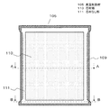
図1は本発明の実施の形態1における住宅の断熱壁の断面図であり、図2は同実施の形態の住宅の既存の壁に配置した胴縁と真空断熱材との配置関係を示す模式図である。また、図3は同実施の形態の住宅の断熱壁に用いた真空断熱材を示す模式図であり、図4、図5は図3をA−A線、B−B線にてそれぞれ切断した真空断熱材の断面図である。
(Embodiment 1)
FIG. 1 is a cross-sectional view of a heat insulating wall of a house in Embodiment 1 of the present invention, and FIG. 2 is a schematic diagram showing an arrangement relationship between a trunk edge and a vacuum heat insulating material arranged on an existing wall of the house of the same embodiment. FIG. Moreover, FIG. 3 is a schematic diagram showing a vacuum heat insulating material used for the heat insulating wall of the house of the embodiment, and FIGS. 4 and 5 are cut along lines AA and BB in FIG. It is sectional drawing of a vacuum heat insulating material.
図1、図2に示すように、本実施の形態の住宅の断熱壁101は、外壁材102と柱103と内壁材104で構成される住宅の既存の壁において、内壁材104の室内側の面から順に、内壁材104の室内側の面に配置された複数の真空断熱材105と、真空断熱材105の室内側の面に配置された胴縁106と、胴縁106の室内側に固定され真空断熱材105と胴縁106とを室内側から覆い隠す突き刺し防止板107とがそれぞれ配置されている。
As shown in FIGS. 1 and 2, the
真空断熱材105、胴縁106、突き刺し防止板107は、それぞれタッカーからなる固定具108により、真空断熱材105の熱溶着部109を介して内壁材104に取り付けられている。固定具108は真空断熱材105の熱溶着部109を貫通している。
The vacuum
また、図3、図4、図5に示すように、真空断熱材105は、内面に熱溶着層112を有するガスバリア性の外被材113で芯材114を減圧密封してなり、芯材114の厚み方向に見たときに外被材113の間に芯材114がある芯材部110と、芯材114の厚み方向に見たときに外被材113の間に芯材114がない芯材なし部111とを有する。また、芯材114の角部付近に位置する芯材なし部111は、芯材部110の面に対して波打っており、また、芯材114の角部付近から離間した箇所に位置する芯材なし部111は、芯材部110の面に対して略平行となっている。なお、熱溶着部109は芯材なし部111における対向する外被材113同士が熱溶着された部分を指す。
As shown in FIGS. 3, 4, and 5, the vacuum
なお、図1、図2に示すように、真空断熱材105は、芯材114の角部付近に位置する芯材なし部111の波打ちが解消されるように、固定具108を用いて内装材104へ固定されており、芯材なし部111が胴縁106に密着している。
As shown in FIGS. 1 and 2, the vacuum
また、真空断熱材105の角部付近に位置する芯材なし部111が胴縁106の形状に沿うように、胴縁106の反室内側の面が真空断熱材105の芯材部110と接触せずに芯材なし部111の少なくとも一部と接する。
Further, the surface on the inner side of the
以上のように本実施の形態の住宅は、外壁材102と柱103と内壁材104で構成され室内空間を形成する住宅の既存の壁と、内壁材104の室内側の面の少なくとも一部に配置された複数の真空断熱材105と、真空断熱材105の室内側の面に配置された胴縁106と、胴縁106の室内側に固定され真空断熱材105と胴縁106とを室内側から覆い隠す突き刺し防止板107とを有する住宅であって、真空断熱材105は、内面に熱溶着層112を有するガスバリア性の外被材113で芯材114を減圧密封してなり、芯材114の厚み方向に見たときに外被材113の間に芯材114がある芯材部110と、芯材114の厚み方向に見たときに外被材113の間に芯材114がない芯材なし部111とを有し、真空断熱材105の角部付近に位置する芯材なし部111が胴縁106の形状に沿うように、胴縁106の反室内側の面が真空断熱材105の芯材部110と接触せずに芯材なし部111の少なくとも一部と接することを特徴とする。
As described above, the house according to the present embodiment is formed on at least a part of the existing wall of the house formed of the
胴縁106を介して真空断熱材105を、室内空間を形成する壁の内壁材104の室内側の面へ固定する際、真空断熱材105の角部付近に位置する芯材なし部111が胴縁106の形状に沿うように配置することで、芯材部110周辺に位置する芯材なし部111の変形に沿って胴縁106が変形することを防止することができ、また胴縁106を壁、天井、床いずれかの室内側の面に対して平行に設置することができる。これにより、突き刺し防止板107を壁、天井、床等の内壁と平行に設置でき、突き刺し防止板107同士の継ぎ目に発生する段差を抑制することができる。
When the vacuum
(実施の形態2)
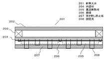
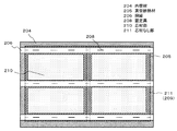
図6は本発明の実施の形態2における住宅の断熱天井の断面図であり、図7は同実施の形態の住宅の既存の天井に配置した胴縁と真空断熱材との配置関係を示す模式図である。また、図8は同実施の形態の住宅の断熱天井に用いた真空断熱材を示す模式図であり、図9、図10は図8をC−C線、D−D線にてそれぞれ切断した真空断熱材の断面図である。
(Embodiment 2)
FIG. 6 is a cross-sectional view of a heat insulating ceiling of a house according to Embodiment 2 of the present invention, and FIG. 7 is a schematic diagram showing an arrangement relationship between a trunk edge and a vacuum heat insulating material arranged on the existing ceiling of the house of the same embodiment. FIG. Moreover, FIG. 8 is a schematic diagram showing a vacuum heat insulating material used for the heat insulating ceiling of the house of the same embodiment, and FIG. 9 and FIG. 10 are cut along FIG. 8 along CC line and DD line, respectively. It is sectional drawing of a vacuum heat insulating material.
図6、図7において住宅の断熱天井201は、外壁材202と柱203と内壁材204で構成される住宅の既存の天井において、内壁材204の室内側の面から順に真空断熱材205と、胴縁206と、突き刺し防止板207とがそれぞれ配置されており、真空断熱材205、胴縁206、突き刺し防止板207はそれぞれタッカーからなる固定具208により、真空断熱材205の熱溶着部209を介して内壁材204に取り付けられている。固定具208は真空断熱材205の熱溶着部209を貫通している。
このとき、真空断熱材205は、隣接する真空断熱材205と芯材なし部211同士が重なるよう内壁材に取り付けられている。また、胴縁206は、胴縁206の反室内側の面が真空断熱材205の芯材部210と接触せずに芯材なし部211と接するよう配置されている。
6 and 7, the
At this time, the vacuum
また、図8、図9、図10において、真空断熱材205は、内面に熱溶着層212を有するガスバリア性の外被材213と、複数の芯材214とを有し、熱溶着層212同士が対向する外被材213の間に芯材214が熱溶着部209によって離間される独立した真空空間内に位置するように減圧密封され、対向する熱溶着層212同士のうち芯材214の少なくとも周縁部の全てが熱溶着されている。また、芯材部210の角部同士を結ぶ延長線付近に位置する芯材なし部211は、芯材部210の面に対して波打っており、また、芯材部210の角部同士を結ぶ延長線から離間した箇所に位置する芯材なし部211は、芯材部210の面に対して略平行となっている。なお、熱溶着部209は芯材なし部211における対向する外被材213同士が熱溶着された部分を指しており、本実施の形態では、芯材なし部211の全ての部分が熱溶着部209となっている。
8, 9, and 10, the vacuum
なお、図6、図7に示すように、真空断熱材205は、芯材214の角部付近に位置する芯材なし部211の波打ちが解消されるように、固定具208を用いて内装材204へ固定されており、芯材なし部211が胴縁206に密着している。
As shown in FIGS. 6 and 7, the vacuum
以上のように本実施の形態の住宅は、外壁材202と柱203と内壁材204で構成され室内空間を形成する住宅の既存の天井と、内壁材204の室内側の面の少なくとも一部に配置された複数の真空断熱材205と、真空断熱材205の室内側の面に配置された胴縁206と、胴縁206の室内側に固定され真空断熱材205と胴縁206とを室内側から覆い隠す突き刺し防止板207とを有する住宅であって、真空断熱材205は、厚み方向に略垂直な方向に互いに所定間隔離して配置された複数の芯材214を有し、熱溶着層212同士が対向するガスバリア性の外被材213の間に芯材214のそれぞれが互いに独立した空間内に位置するように、外被材213の間に芯材214が無い部分の外被材213同士を密着させて、密着した外被材213同士を熱溶着することで、複数の芯材214を外被材213内に減圧密封してなり、外被材213同士が密着する全ての部分の外被材213同士が熱溶着されており、芯材214の厚み方向に見たときに外被材213の間に芯材214がある芯材部210と、芯材214の厚み方向に見たときに外被材213の間に芯材214がない芯材なし部211とを有し、真空断熱材205の角部付近に位置する芯材なし部211が胴縁206の形状に沿うように、胴縁206の反室内側の面が真空断熱材205の芯材部210と接触せずに芯材なし部211の少なくとも一部と接することを特徴とする。
As described above, the house according to the present embodiment is formed on the existing ceiling of the house, which includes the
上記構成において、真空断熱材205の角部付近に位置する真空断熱材205の芯材なし部211が胴縁206の形状に沿うように、胴縁206の反室内側の面が真空断熱材205の芯材部210と接触せずに芯材なし部211の少なくとも一部と接するようにしたことに加え、真空断熱材205は、厚み方向に略垂直な方向に互いに所定間隔離して配置された複数の芯材214を有し、熱溶着層212同士が対向するガスバリア性の外被材213の間に芯材214のそれぞれが互いに独立した空間内に位置するように、外被材213の間に芯材214が無い部分の外被材213同士を密着させて、密着した外被材213同士を熱溶着することで、複数の芯材214を外被材213内に減圧密封してなり、外被材213同士が密着する全ての部分の外被材213同士が熱溶着されていることから、複数の芯材214を減圧密封する際に、外被材213は同時に複数の芯材214の形状に沿うため、隣接する芯材214と芯材214との間に位置する芯材なし部211は、一つの芯材214を減圧密封した場合に得られる芯材なし部に比べて平滑となる。また、真空断熱材205の芯材なし部211と、周囲の真空断熱材205の芯材なし部と211が重なる箇所においても、芯材なし部211の波打ちが解消されるように固定具208を用いて内装材204へ固定しているため、芯材なし部211同士の重なりが胴縁206の設置状態に影響を及ぼさない。これにより、芯材部210周辺に位置する芯材なし部211の変形に沿って胴縁206が変形することを防止することができ、また胴縁206を壁、天井、床いずれかの室内側の面に対して平行に設置することができる。これにより、突き刺し防止板207を壁、天井、床等の内壁と平行に設置でき、突き刺し防止板207同士の継ぎ目に発生する段差を抑制することができる。
In the above-described configuration, the surface on the inner side of the
(実施の形態3)
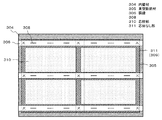
図11は、本発明の実施の形態3における住宅の断熱床の断面図であり、図12は同実施の形態の住宅の既存の床に配置した胴縁と真空断熱材との配置関係を示す模式図である。なお、本実施の形態の住宅の断熱床に用いた真空断熱材は実施の形態2の真空断熱材205と同じ構成である。
(Embodiment 3)
FIG. 11 is a cross-sectional view of a heat insulating floor of a house in Embodiment 3 of the present invention, and FIG. 12 shows an arrangement relationship between a trunk edge and a vacuum heat insulating material arranged on the existing floor of the house of the same embodiment. It is a schematic diagram. In addition, the vacuum heat insulating material used for the heat insulation floor of the house of this Embodiment is the same structure as the vacuum
図11、図12において、住宅の断熱床301は、外壁材302と柱303と内壁材304で構成される住宅の既存の床において、内壁材304の室内側の面から順に胴縁306と、真空断熱材305と、突き刺し防止板307とがそれぞれ配置されており、真空断熱材305、胴縁306、突き刺し防止板307はそれぞれタッカーからなる固定具308により、真空断熱材305の熱溶着部309を介して胴縁306または内壁材304に取り付けられている。固定具308は真空断熱材305の熱溶着部309を貫通している。このとき、真空断熱材305の芯材部310と、隣接する真空断熱材305の芯材なし部311とが重なり合うように胴縁306または内壁材304へ取り付けられている。また、胴縁306は、胴縁306の室内側の面が真空断熱材305の芯材部310と接触せずに芯材なし部311と接するよう配置されている。なお、熱溶着部309は芯材なし部311における対向する外被材同士が熱溶着された部分を指しており、本実施の形態では、芯材なし部311の全ての部分が熱溶着部309となっている。
11 and 12, the
なお、図11、図12に示すように、真空断熱材305は、芯材314の角部付近に位置する芯材なし部311の波打ちが解消されるように、複数の固定具308を用いて胴縁306へ固定されており、芯材なし部311が胴縁306に密着している。
As shown in FIGS. 11 and 12, the vacuum
以上のように本実施の形態の住宅は、外壁材302と柱303と内壁材304で構成され室内空間を形成する住宅の既存の床と、内壁材304の室内側の面の少なくとも一部に配置された複数の真空断熱材305と、真空断熱材305の反室内側の面に配置された胴縁306と、胴縁306の室内側に固定され真空断熱材305と胴縁306とを室内側から覆い隠す突き刺し防止板307とを有する住宅であって、真空断熱材305は、厚み方向に略垂直な方向に互いに所定間隔離して配置された複数の芯材を有し、熱溶着層同士が対向するガスバリア性の外被材の間に芯材のそれぞれが互いに独立した空間内に位置するように、外被材の間に芯材が無い部分の外被材同士を密着させて、密着した外被材同士を熱溶着することで、複数の芯材を外被材内に減圧密封してなり、外被材同士が密着する全ての部分の外被材同士が熱溶着されており、芯材の厚み方向に見たときに外被材の間に芯材がある芯材部310と、芯材の厚み方向に見たときに外被材の間に芯材がない芯材なし部311とを有し、真空断熱材305の芯材部310と、隣接する真空断熱材305の芯材なし部311とが重なり合うように内壁材304へ取り付けられ、真空断熱材305の角部付近に位置する芯材なし部311が胴縁306の形状に沿うように、胴縁306の室内側の面が真空断熱材305の芯材部310と接触せずに芯材なし部311の少なくとも一部と接することを特徴とする。
As described above, the house according to the present embodiment is formed on at least a part of the existing floor of the house formed of the
上記構成において、真空断熱材305の角部付近に位置する真空断熱材305の芯材なし部311が胴縁306の形状に沿うように、胴縁306の室内側の面が真空断熱材305の芯材部310と接触せずに芯材なし部311の少なくとも一部と接するようにしたことに加え、真空断熱材305は、厚み方向に略垂直な方向に互いに所定間隔離して配置された複数の芯材を有し、熱溶着層同士が対向するガスバリア性の外被材の間に芯材のそれぞれが互いに独立した空間内に位置するように、外被材の間に芯材が無い部分の外被材同士を密着させて、密着した外被材同士を熱溶着することで、複数の芯材を外被材内に減圧密封してなり、外被材同士が密着する全ての部分の外被材同士が熱溶着されていることから、複数の芯材を減圧密封する際に、外被材は同時に複数の芯材の形状に沿うため、芯材とその芯材の周囲に位置する他の芯材との間に位置する芯材なし部311は、一つの芯材を減圧密封した場合に得られる芯材なし部に比べて平滑となる。また、真空断熱材305の芯材なし部311と、周囲の真空断熱材305の芯材なし部311とが重なる箇所においても、芯材なし部311の波打ちが解消されるように固定具308を用いて内装材304へ固定しているため、芯材なし部311同士の重なりが胴縁306の設置状態に影響を及ぼさない。これにより、芯材部310周辺に位置する芯材なし部311の変形に沿って胴縁306が変形することを防止することができ、また胴縁306を壁、天井、床いずれかの室内側の面に対して平行に設置することができる。これにより、突き刺し防止板307を壁、天井、床等の内壁と平行に設置でき、突き刺し防止板307同士の継ぎ目に発生する段差を抑制することができる。
In the above-described configuration, the inner surface of the
本発明の住宅は、真空断熱材に起因する突き刺し防止板等の壁同士における継ぎ目に発生する段差を抑制することができるため、新築住宅や、既存住宅、商業施設、工場、事務所などの建物にも適用可能である。 Since the housing of the present invention can suppress the level difference occurring at the seam between the walls such as the stab prevention plate due to the vacuum heat insulating material, the building such as a new house, an existing house, a commercial facility, a factory, an office, etc. It is also applicable to.
101 断熱壁
104,204,304 内壁材
105,205,305 真空断熱材
106,206,306 胴縁
107,207,307 突き刺し防止板
108,208,308 固定具
110,210,310 芯材部
111,211,311 芯材なし部
112,212 熱溶着層
113、213 外被材
114、214 芯材
201 断熱天井
301 断熱床
101
Claims (4)
Priority Applications (1)
| Application Number | Priority Date | Filing Date | Title |
|---|---|---|---|
| JP2008184438A JP5446151B2 (en) | 2008-07-16 | 2008-07-16 | Vacuum insulation for homes and homes |
Applications Claiming Priority (1)
| Application Number | Priority Date | Filing Date | Title |
|---|---|---|---|
| JP2008184438A JP5446151B2 (en) | 2008-07-16 | 2008-07-16 | Vacuum insulation for homes and homes |
Publications (2)
| Publication Number | Publication Date |
|---|---|
| JP2010024638A true JP2010024638A (en) | 2010-02-04 |
| JP5446151B2 JP5446151B2 (en) | 2014-03-19 |
Family
ID=41730719
Family Applications (1)
| Application Number | Title | Priority Date | Filing Date |
|---|---|---|---|
| JP2008184438A Expired - Fee Related JP5446151B2 (en) | 2008-07-16 | 2008-07-16 | Vacuum insulation for homes and homes |
Country Status (1)
| Country | Link |
|---|---|
| JP (1) | JP5446151B2 (en) |
Citations (5)
| Publication number | Priority date | Publication date | Assignee | Title |
|---|---|---|---|---|
| JPH09287240A (en) * | 1996-04-22 | 1997-11-04 | Nippon Steel Corp | Wall board connection structure |
| JPH10292524A (en) * | 1997-04-11 | 1998-11-04 | Ig Tech Res Inc | Heat insulation panel and heat insulation substrate with the panel utilized |
| JP2002146937A (en) * | 2000-11-15 | 2002-05-22 | Asahi Fiber Glass Co Ltd | Heat insulating execution method for house, and heat insulating material for ceiling |
| JP3557513B2 (en) * | 1998-03-10 | 2004-08-25 | 有限会社柴野製作所 | Laying construction structure of building interior panels |
| JP2008050814A (en) * | 2006-08-23 | 2008-03-06 | Misawa Homes Co Ltd | Exterior wall structure and exterior wall panel for building |
-
2008
- 2008-07-16 JP JP2008184438A patent/JP5446151B2/en not_active Expired - Fee Related
Patent Citations (5)
| Publication number | Priority date | Publication date | Assignee | Title |
|---|---|---|---|---|
| JPH09287240A (en) * | 1996-04-22 | 1997-11-04 | Nippon Steel Corp | Wall board connection structure |
| JPH10292524A (en) * | 1997-04-11 | 1998-11-04 | Ig Tech Res Inc | Heat insulation panel and heat insulation substrate with the panel utilized |
| JP3557513B2 (en) * | 1998-03-10 | 2004-08-25 | 有限会社柴野製作所 | Laying construction structure of building interior panels |
| JP2002146937A (en) * | 2000-11-15 | 2002-05-22 | Asahi Fiber Glass Co Ltd | Heat insulating execution method for house, and heat insulating material for ceiling |
| JP2008050814A (en) * | 2006-08-23 | 2008-03-06 | Misawa Homes Co Ltd | Exterior wall structure and exterior wall panel for building |
Also Published As
| Publication number | Publication date |
|---|---|
| JP5446151B2 (en) | 2014-03-19 |
Similar Documents
| Publication | Publication Date | Title |
|---|---|---|
| JP5543698B2 (en) | Thermal insulation repair method for existing walls and thermal insulation repair method for existing buildings | |
| EP1987208B1 (en) | Thermal insulation plate comprising an insulating core and an elevated surface portion, thermally insulated structure of such plates and method for constructing such structure | |
| JP2010047902A (en) | Heat insulating wall and building and house having heat insulating wall | |
| JP2009243256A (en) | Building and house | |
| KR20170088400A (en) | Thermal insulation system and kit and method for installing same | |
| JP5991233B2 (en) | Inner wall insulation structure and inner wall panel | |
| JP5077058B2 (en) | Insulation wall | |
| JP2010007405A (en) | Heat insulating wall, and building and house applying the same | |
| JP5446151B2 (en) | Vacuum insulation for homes and homes | |
| JP2018003298A (en) | Heat insulation structure of building and construction method of building thereof | |
| JP2010013839A (en) | Heat insulating wall | |
| JP5446357B2 (en) | Vacuum insulation used in buildings and buildings | |
| JPH10169016A (en) | Building unit connecting structure | |
| JP2010013863A (en) | House | |
| JP5514015B2 (en) | Interior building materials with insulation | |
| JP5217594B2 (en) | Insulated walls and buildings and houses to which they are applied | |
| JP5494761B2 (en) | Insulation wall | |
| JP2008156910A (en) | Building member and building structure | |
| JP2008095365A (en) | Building | |
| JP5239389B2 (en) | Insulated wall and house with it | |
| JP3821289B2 (en) | Airtight structure at the connecting corner of the beam | |
| JP5286979B2 (en) | Insulating wall, vacuum heat insulating material used for it, and buildings and houses to which it is applied | |
| JP6422687B2 (en) | Insulated airtight outer wall structure | |
| KR101289241B1 (en) | Wall Having Hybrid Panel And Forming Method Of Wall Having Hybrid Panel | |
| JP2009215868A (en) | Building and house |
Legal Events
| Date | Code | Title | Description |
|---|---|---|---|
| A621 | Written request for application examination |
Free format text: JAPANESE INTERMEDIATE CODE: A621 Effective date: 20110314 |
|
| RD01 | Notification of change of attorney |
Free format text: JAPANESE INTERMEDIATE CODE: A7421 Effective date: 20110413 |
|
| A977 | Report on retrieval |
Free format text: JAPANESE INTERMEDIATE CODE: A971007 Effective date: 20120810 |
|
| A131 | Notification of reasons for refusal |
Free format text: JAPANESE INTERMEDIATE CODE: A131 Effective date: 20120821 |
|
| A521 | Written amendment |
Free format text: JAPANESE INTERMEDIATE CODE: A523 Effective date: 20121022 |
|
| RD01 | Notification of change of attorney |
Free format text: JAPANESE INTERMEDIATE CODE: A7421 Effective date: 20121213 |
|
| A131 | Notification of reasons for refusal |
Free format text: JAPANESE INTERMEDIATE CODE: A131 Effective date: 20130507 |
|
| A521 | Written amendment |
Free format text: JAPANESE INTERMEDIATE CODE: A523 Effective date: 20130614 |
|
| TRDD | Decision of grant or rejection written | ||
| A01 | Written decision to grant a patent or to grant a registration (utility model) |
Free format text: JAPANESE INTERMEDIATE CODE: A01 Effective date: 20131203 |
|
| A61 | First payment of annual fees (during grant procedure) |
Free format text: JAPANESE INTERMEDIATE CODE: A61 Effective date: 20131216 |
|
| R151 | Written notification of patent or utility model registration |
Ref document number: 5446151 Country of ref document: JP Free format text: JAPANESE INTERMEDIATE CODE: R151 |
|
| LAPS | Cancellation because of no payment of annual fees |