JP2010022426A - Extraneous matter remover - Google Patents
Extraneous matter remover Download PDFInfo
- Publication number
- JP2010022426A JP2010022426A JP2008184059A JP2008184059A JP2010022426A JP 2010022426 A JP2010022426 A JP 2010022426A JP 2008184059 A JP2008184059 A JP 2008184059A JP 2008184059 A JP2008184059 A JP 2008184059A JP 2010022426 A JP2010022426 A JP 2010022426A
- Authority
- JP
- Japan
- Prior art keywords
- ions
- ion
- brush
- positive
- negative
- Prior art date
- Legal status (The legal status is an assumption and is not a legal conclusion. Google has not performed a legal analysis and makes no representation as to the accuracy of the status listed.)
- Pending
Links
Images


Abstract
Description
この発明は、衣類等の対象物から塵埃や汚れ等の付着物を除去するための付着物除去具に関する。 The present invention relates to a deposit removing tool for removing deposits such as dust and dirt from an object such as clothing.
従来、衣類、布等の対象物から塵埃や汚れ等の付着物を除去するための付着物除去具としては、例えば、ブラシが広く用いられている。 2. Description of the Related Art Conventionally, for example, a brush has been widely used as a deposit removing tool for removing deposits such as dust and dirt from objects such as clothes and cloth.
従来のブラシは、本体に細い繊維状の毛が植毛された構成になっている。ブラシの毛は、繊維状の獣毛や植物毛や樹脂毛である。このようなブラシを用いて、衣類表面に付着した塵や埃といった粒子を、毛が衣類等の表面に接するときの物理的な作用によって、除去することができる。したがって、従来のブラシは、外出先から帰宅した際等に、室内に入る前に玄関等で、衣類表面に付着した塵や埃を除去するために用いられるものであった。 Conventional brushes have a structure in which fine fibrous hairs are implanted in the main body. The brush hair is fibrous animal hair, plant hair, or resin hair. Using such a brush, particles such as dust and dirt adhering to the clothing surface can be removed by a physical action when the hair contacts the clothing surface. Therefore, the conventional brush is used to remove dust and dirt adhering to the clothing surface at the entrance or the like before entering the room when returning home from the outside.
さらに、近年においては、ガス状物質を発生させる装置をブラシに組み合わせた形態により、新たな効果を得るような商品が開発されている。例えば、ブラシやブラシ搭載ドライヤーに、マイナスイオンやオゾンといったガス状物質を放出する手段を組み合わせたものがある。 Further, in recent years, a product that has a new effect has been developed by combining an apparatus for generating a gaseous substance with a brush. For example, there are brushes and brush-mounted dryers combined with means for releasing gaseous substances such as negative ions and ozone.
例えば、特開2003−61736号公報(特許文献1)には、空気の吐気口とは別に、マイナスイオンを吐出するイオン吐出口を形成したブラシ付きヘアードライヤーが記載されている。このブラシ付きヘアードライヤーでは、マイナスイオンを含んだ温風を毛髪に吹き付けて、毛髪の乾燥やセットだけでなく、毛髪のトリートメントを行なう。 For example, Japanese Unexamined Patent Publication No. 2003-61736 (Patent Document 1) describes a hair dryer with a brush in which an ion discharge port for discharging negative ions is formed separately from an air discharge port. In this hair dryer with a brush, warm air containing negative ions is blown onto the hair to treat the hair as well as drying and setting the hair.
特開2007−105144号公報(特許文献2)には、マイナスイオン発生用の放電ユニットやトランスが本体に配置されているヘアーセッターが記載されている。このヘアーセッターの本体には、アタッチメントとしてブローブラシ、ロールブラシなどのアタッチメントを取り付けることができる。マイナスイオンは、乾燥風によって吹き出されて髪に供給される。 Japanese Patent Laying-Open No. 2007-105144 (Patent Document 2) describes a hair setter in which a discharge unit and a transformer for generating negative ions are arranged in a main body. An attachment such as a blow brush or a roll brush can be attached to the body of the hair setter as an attachment. Negative ions are blown out by dry air and supplied to the hair.
特開2005−95638号公報(特許文献3)には、マイナスイオンを発生させるイオン発生器を備える整髪用ブラシが記載されている。 Japanese Patent Laying-Open No. 2005-95638 (Patent Document 3) describes a hair styling brush including an ion generator that generates negative ions.
特開昭60−160904号公報(特許文献4)には、負イオンを発生させるヘアブラシが記載されている。 Japanese Patent Application Laid-Open No. 60-160904 (Patent Document 4) describes a hairbrush that generates negative ions.
実開平3−74819号公報(特許文献5)には、髪および頭皮の殺菌、脱臭、美容を行なうために、ブラシ支持本体の中空部にオゾン発生器とモータファンを収納した髪用ブラシが記載されている。 Japanese Utility Model Publication No. 3-74819 (Patent Document 5) describes a hair brush in which an ozone generator and a motor fan are housed in a hollow portion of a brush support body in order to sterilize, deodorize, and beauty hair and scalp. Has been.
このように、従来のブラシにおいては、マイナスイオンやオゾンといったガス状物質を放出する手段にブラシを組み合わせることによって、衣類表面に付着した塵埃を除去したり、髪を整えたりするとともに、マイナスイオンやオゾンを髪や頭皮に照射し、オゾンによって脱臭したり、マイナスイオンを髪に供給したりすることができる。 As described above, in the conventional brush, by combining the brush with a means for releasing gaseous substances such as negative ions and ozone, dust attached to the surface of the clothes is removed, and the hair is trimmed. It is possible to irradiate hair and scalp with ozone and deodorize with ozone, or supply negative ions to hair.
ところで、衣類や布類などの対象物に付着する付着物は、塵埃のような固体成分だけではない。衣類等には、例えば、ニオイを発生させる臭気物質が付着することがある。臭気物質は、衣類等の対象物から脱離して、ニオイとなる。 By the way, the adhering substances adhering to objects such as clothes and cloth are not only solid components such as dust. For example, odorous substances that generate odor may adhere to clothes and the like. Odorous substances are detached from objects such as clothes and become odorous.
近年、人々の清潔志向が急激に高まっており、特にニオイを効果的に除去するニーズが高まっている。衣類等の対象物に付着するニオイの代表的なものとしては、タバコ付着臭(主に、アンモニア系、酢酸系、アルデヒド系、ニコチン系)、人体から発せられる臭気としては、汗臭(主に、吉草酸といった脂肪酸系の成分)、加齢臭(主に、ノネナール)、食品に起因する臭気としては、調理臭(主に、トリメチルアミン系)、腐敗臭(主に、硫化水素)等が挙げられる。 In recent years, people's desire for cleanliness has increased rapidly, and in particular, there has been an increasing need for effective removal of odors. Typical examples of odors that adhere to objects such as clothing include cigarette odors (mainly ammonia-based, acetic acid-based, aldehyde-based, and nicotine-based), and odors emitted from the human body include sweat odor (mainly Fatty acid components such as valeric acid), aging odors (mainly nonenal), and food-related odors include cooking odors (mainly trimethylamine), spoilage odors (mainly hydrogen sulfide), etc. It is done.
従来のブラシを用いて、衣類等の対象物の表面の塵埃を除去することによって、塵埃に付着している臭気物質を塵埃とともに対象物の表面から除去することができる。 By using a conventional brush to remove dust on the surface of an object such as clothing, odorous substances adhering to the dust can be removed together with the dust from the surface of the object.
なお、特許第3680121号公報(特許文献6)には、イオン発生装置を搭載して室内の空気中に正イオンとしてH+(H2O)m(mは任意の自然数)と負イオンとしてO2 −(H2O)n(nは任意の自然数)を放出し、イオンの効果により空気の清浄化を行う空気清浄機や空気調和機が記載されている。空気中に放出されたこれらの正イオンと負イオンは、正イオンと負イオンとの間で化学反応し、活性物質としての過酸化水素(H2O2)または水酸基ラジカル(・OH)となる。過酸化水素または水酸基ラジカルは、浮遊粒子または浮遊細菌から水素を抜き取る酸化反応を行うことで、浮遊粒子を不活性化することができ、または浮遊細菌を殺菌することができることが知られている。 In Japanese Patent No. 3680121 (Patent Document 6), an ion generator is mounted and H + (H 2 O) m (m is an arbitrary natural number) and O as negative ions in the indoor air. 2 - (H 2 O) n (n is an arbitrary natural number) emits an air purifier or air conditioner to perform the cleaning of the air is described by the effect of ions. These positive ions and negative ions released into the air chemically react between the positive ions and the negative ions to become hydrogen peroxide (H 2 O 2 ) or a hydroxyl radical (.OH) as an active substance. . It is known that hydrogen peroxide or hydroxyl radical can inactivate suspended particles or sterilize suspended bacteria by performing an oxidation reaction that extracts hydrogen from suspended particles or suspended bacteria.
また、米国特許第4210847号明細書(特許文献7)には、円筒管中央にコロナ放電針を配置し、対向電極を配置したイオン風装置の構成について記載されている。このイオン風装置は、放電現象を発生させるための放電現象発生電極として、先端が尖がった形状の針型電極と、例えばメッシュ状に形成されて針型電極に対して対向して配置される対向電極から構成されているイオン風装置が記載されている。針型電極と対向電極は、間隔をあけて配置されている。
しかしながら、臭気成分は分子レベルで衣類や布等の対象物の表面に付着したものであり、塵埃と比較して極端に小さい。そのため、特に、対象物が衣類や布類などの繊維構造体である場合には、繊維状の獣毛や植物毛や樹脂毛によって構成されるブラシの物理的な作用によって臭気成分を対象物の表面から除去することは難しい。 However, the odor component is attached to the surface of an object such as clothing or cloth at the molecular level, and is extremely small compared to dust. Therefore, especially when the object is a fiber structure such as clothing or cloth, the odor component is removed from the object by the physical action of a brush composed of fibrous animal hair, plant hair, or resin hair. It is difficult to remove from the surface.
このような、ブラシを用いて除去することができないニオイを除去するためには、従来、水と洗剤を用いて衣類等の対象物を洗濯している。対象物を洗濯して、臭気成分を対象物から除去することによって、対象物からニオイを除去することができる。 In order to remove such odors that cannot be removed using a brush, conventionally, objects such as clothes are washed with water and a detergent. By washing the object and removing odor components from the object, odors can be removed from the object.
しかし、水や洗剤を用いる洗濯によるニオイの除去は、時間がかかり、また、洗濯後に衣類等の対象物を乾燥させる必要もある。 However, removing odors by washing with water or detergent takes time, and it is necessary to dry objects such as clothes after washing.
臭気成分を対象物から除去するための洗濯以外の方法としては、例えば、半導体工場や、液晶ディスプレイ工場といったクリーンルーム入口に設けるエアーシャワーのように、強い風が発生する環境を作り、気流に乗せて、臭気成分を吹き飛ばす手法が採用されている。このようにして臭気成分を吹き飛ばす手法を用いれば、衣類や布類に付着した臭気成分を除去することができる。 As a method other than washing to remove odorous components from the object, create an environment where strong wind is generated, such as an air shower provided at the entrance of a clean room such as a semiconductor factory or a liquid crystal display factory, and place it on the airflow. A method of blowing off odor components is employed. Thus, if the method of blowing off an odor component is used, the odor component adhering to clothing and cloth can be removed.
しかし、一般家庭においてはこのようなエアーシャワー装置を設けることは、コストや設置場所等を考慮すれば実質的には不可能である。 However, it is practically impossible to provide such an air shower device in a general home in consideration of cost, installation location, and the like.
また、ニオイを除去する別の方法としては、消臭液の成分でニオイを包み込むことにより、消臭効果を発揮させる方法がある。消臭液は広く市販されており、例えば、スプレーで消臭液を噴霧することにより、ニオイを除去することができるものが販売されている。 As another method for removing odors, there is a method of exerting a deodorizing effect by wrapping odors with components of a deodorizing liquid. Deodorant liquids are widely available on the market. For example, products that can remove odors by spraying the deodorant liquid with a spray are on the market.
しかし、消臭液の成分で臭気物質を包みこんでも、臭気物質そのものは存在しているために、時間が経つと、臭気物質を包み込んでいた消臭物質が再び脱離する。臭気物質から消臭物質が脱離すると、再度ニオイが発生する。このように、消臭物質を用いることによって、短期的なニオイ抑制効果は得られるものの、長期的な除去効果を維持することは難しい。 However, even if the odorous substance is wrapped with the components of the deodorizing liquid, the odorous substance itself exists, so that the deodorizing substance encapsulating the odorous substance is detached again over time. When the deodorizing substance is detached from the odorous substance, odor is generated again. As described above, by using a deodorizing substance, although a short-term odor suppression effect can be obtained, it is difficult to maintain a long-term removal effect.
実開平3−74819号公報(特許文献5)に記載の髪用ブラシのように、オゾンを発生させる場合には、オゾンによって髪や頭皮の臭気物質を脱臭することができるが、オゾン自体が特有のニオイを発する。また、オゾンは有害である。 When generating ozone as in the hair brush described in Japanese Utility Model Publication No. 3-74819 (Patent Document 5), odorous substances in hair and scalp can be deodorized by ozone, but ozone itself is unique. The odor is emitted. Ozone is also harmful.
また、特開2003−61736号公報(特許文献1)に記載のブラシ付きヘアードライヤー、特開2007−105144号公報(特許文献2)に記載のヘアーセッター、特開2005−95638号公報(特許文献3)に記載の整髪用ブラシ、特開昭60−160904号公報(特許文献4)に記載のヘアブラシのように、マイナスイオン(負イオン)を髪に供給するブラシでは、マイナスイオンによって髪や頭皮の潤いを高めることはできても、マイナスイオンではニオイを除去することはできない。 Further, a hair dryer with a brush described in JP-A-2003-61736 (Patent Document 1), a hair setter described in JP-A-2007-105144 (Patent Document 2), and JP-A-2005-95638 (Patent Document). 3) and a brush for supplying negative ions (negative ions) to hair, such as a hair brush described in Japanese Patent Application Laid-Open No. 60-160904 (Patent Document 4), the hair and scalp by negative ions. Although we can increase the moisture, we cannot remove odors with negative ions.
また、これらのブラシでは、イオンやオゾンを空気とともに髪に供給しているので、気流とともにイオンやオゾンが分散されてしまう。気流とともにイオンやオゾンを分散させることによって、塵埃等の付着物も分散してしまう。塵埃等に臭気成分が付着している場合には、塵埃等が分散することによって、臭気成分が分散し、広い範囲でニオイが発生することになる。また、脱臭効果を有するオゾンも、気流とともに広い範囲に分散されることによって、髪に付着している臭気成分を脱臭することができなくなってしまう。 Moreover, in these brushes, since ions and ozone are supplied to the hair together with air, the ions and ozone are dispersed together with the airflow. By dispersing ions and ozone together with the air flow, deposits such as dust are also dispersed. When an odor component adheres to dust or the like, the odor component is dispersed by the dispersion of the dust or the like, and odor is generated in a wide range. Further, ozone having a deodorizing effect is also dispersed in a wide range together with the air flow, so that the odor component adhering to the hair cannot be deodorized.
そこで、この発明の目的は、効果的に対象物のニオイを除去することが可能な付着物除去具を提供することである。 Accordingly, an object of the present invention is to provide a deposit removal tool that can effectively remove odors from an object.
この発明に従った付着物除去具は、対象物に付着している付着物を対象物から剥離させるための付着物剥離部材と、正イオンとしてH+(H2O)m(mは任意の自然数)と負イオンとしてO2 −(H2O)n(nは任意の自然数)とを発生させるイオン発生部と、イオン発生部から放出された正イオンと負イオンと付着物剥離部材によって対象物から剥離された付着物とを対象物の表面上に形成される所定の領域内に滞留させるための滞留領域形成部とを備える。 The deposit removing tool according to the present invention includes an deposit peeling member for peeling an deposit adhering to an object from the object, and H + (H 2 O) m (m is an arbitrary positive ion). A natural number) and an ion generator that generates O 2 − (H 2 O) n (n is an arbitrary natural number) as negative ions, and positive ions and negative ions released from the ion generator, and an object peeling member. And a staying area forming unit for staying in a predetermined area formed on the surface of the object.
対象物に付着している塵埃や汚れ、花粉、臭気を発生させる臭気物質等の付着物は、付着物剥離部材によって対象物から物理的に剥離される。 Deposits such as dust, dirt, pollen, and odorous substances that generate odor are physically peeled off the target by the deposit peeling member.
付着物剥離部材によって対象物から剥離された付着物は、イオン発生部から放出された正イオンと負イオンとともに、滞留領域形成部によって対象物の表面上の所定の領域内に滞留させられる。このようにして、正イオンと負イオンは、分散することなく、濃度を保ったままで対象物の表面上の所定の領域内に滞留させられる。対象物から剥離された付着物と正イオンと負イオンとは、所定の領域内に滞留させられることによって、互いに衝突しやすくなる。 The deposit separated from the object by the deposit separating member is retained in a predetermined area on the surface of the object by the retention area forming section together with positive ions and negative ions released from the ion generating section. In this way, positive ions and negative ions are retained in a predetermined region on the surface of the object while maintaining the concentration without being dispersed. The deposits, positive ions, and negative ions that have been peeled off from the object are liable to collide with each other by being retained in a predetermined region.
また、正イオンと負イオンは、分散せずに対象物の表面上に形成される所定の領域内に滞留させられることによって、対象物の表面に接触したり、対象物の表面から対象物の内部に入り込んだりしやすくなる。このようにして、付着物剥離部材によって剥離されず、対象物の表面や内部に残っている臭気成分等の付着物にも正イオンと負イオンが接触しやすくなる。 Further, positive ions and negative ions are retained in a predetermined region formed on the surface of the object without being dispersed, thereby contacting the surface of the object or from the surface of the object. It becomes easy to get inside. In this way, positive ions and negative ions are likely to come into contact with adhering substances such as odor components remaining on the surface or inside of the object without being exfoliated by the adhering substance peeling member.
対象物から剥離された付着物や、対象物の表面や内部に残っている付着物が正イオンと負イオンと衝突すると、付着物と正イオンと負イオンとが相互作用する。付着物が臭気を発生させる臭気物質である場合には、臭気物質が正イオンと負イオンと相互作用することによって分解される。このようにして、化学的な作用を利用して、対象物から剥離された付着物が脱臭される。 When the deposit peeled off from the object or the deposit remaining on the surface of the object collides with positive ions and negative ions, the deposits, positive ions and negative ions interact with each other. When the deposit is an odor substance that generates odor, the odor substance is decomposed by interacting with positive ions and negative ions. Thus, the deposit | peeling peeled from the target object is deodorized using a chemical effect | action.
以上のように、この発明の付着物除去具は、付着物剥離部材によって対象物から物理的に付着物を剥離するとともに、正イオンと負イオンの濃度を保持したままで、対象物の表面上に形成された所定の領域内に付着物とともに滞留させて、正イオンと負イオンと付着物との化学的な相互作用によって付着物を脱臭する。 As described above, the deposit removing tool of the present invention physically peels off the deposit from the object by the deposit peeling member, and maintains the positive ion and negative ion concentrations on the surface of the object. The debris is deodorized by a chemical interaction between positive ions, negative ions, and deposits.
このようにすることにより、効果的に付着物のニオイを除去することが可能な付着物除去具を提供することができる。 By doing in this way, the deposit | attachment removal tool which can remove the odor of a deposit | attachment effectively can be provided.
この発明に従った付着物除去具においては、滞留領域形成部は、イオン発生部を囲むように、付着物剥離部材の一部によって形成されていることが好ましい。 In the deposit removal tool according to the present invention, it is preferable that the stay region forming portion is formed by a portion of the deposit peeling member so as to surround the ion generating portion.
このように、滞留領域形成部がイオン発生部を囲むように形成されているので、イオン発生部で発生した正イオンと負イオンを分散させにくく、正イオンと負イオンの濃度を保持しやすくなる。また、滞留領域形成部が付着物剥離部材によって形成されていることによって、付着物剥離部材によって対象物から剥離された付着物が分散される前に、付着物を正イオンと負イオンとともに所定の領域内に滞留させることができる。 As described above, since the retention region forming part is formed so as to surround the ion generating part, it is difficult to disperse the positive ions and negative ions generated in the ion generating part, and the concentration of positive ions and negative ions can be easily maintained. . In addition, since the stay region forming portion is formed by the deposit peeling member, the deposit is removed together with positive ions and negative ions before the deposit peeled from the target by the deposit peeling member is dispersed. It can stay in the area.
この発明に従った付着物除去具においては、イオン発生部は、正イオンを発生させるための正イオン発生部と、負イオンを発生させるための負イオン発生部とを含み、正イオン発生部と負イオン発生部とは別個に形成されていることが好ましい。 In the deposit removing tool according to the present invention, the ion generation unit includes a positive ion generation unit for generating positive ions and a negative ion generation unit for generating negative ions, It is preferably formed separately from the negative ion generation part.
このようにすることにより、正イオン発生部と負イオン発生部とに別々に電圧を印加して、正イオンの発生量と、負イオンの発生量とをそれぞれ調節することができる。 By doing in this way, a voltage is separately applied to a positive ion generation part and a negative ion generation part, and the generation amount of a positive ion and the generation amount of a negative ion can be adjusted, respectively.
この発明に従った付着物除去具は、正イオン発生部と負イオン発生部とを隔てるように配置される隔離部材を備えることが好ましい。 The deposit removing tool according to the present invention preferably includes a separating member arranged so as to separate the positive ion generating part and the negative ion generating part.
このようにすることにより、正イオン発生部で発生した正イオンと負イオン発生部で発生した負イオンとが発生直後に衝突することを防いで、滞留領域形成部によって形成される所定の領域内に到達する前に中和して失活してしまう正イオンと負イオンとを低減することができる。 By doing in this way, it prevents that the positive ion which generate | occur | produced in the positive ion generation | occurrence | production part, and the negative ion which generate | occur | produces in the negative ion generation part collide immediately after generation | occurrence | production, and in the predetermined area | region formed by the residence area | region formation part It is possible to reduce positive ions and negative ions that are neutralized and deactivated before reaching.
この発明に従った付着物除去具においては、イオン発生部は、イオン風を発生させるイオン風発生部を含むことが好ましい。 In the deposit removal tool according to the present invention, the ion generator preferably includes an ion wind generator that generates an ion wind.
このようにすることにより、正イオンと負イオンとを効率よく対象物の表面上に形成される所定の領域に到達させることができる。また、プロペラファンやクロスフローファンのような送風手段を備えることなく風を発生させることができるので、省スペース化、低消費電力化が可能な付着物除去具を提供することができる。 By doing in this way, positive ions and negative ions can efficiently reach a predetermined region formed on the surface of the object. Moreover, since wind can be generated without providing a blowing means such as a propeller fan or a cross flow fan, it is possible to provide a deposit removing tool capable of saving space and reducing power consumption.
この発明に従った付着物除去具は、対象物の表面の帯電の極性を検知するための極性検知部を備え、イオン発生部は、当該付着物除去具が対象物の表面に沿って相対的に移動させられる場合に、対象物に対する当該付着物除去具の相対的な移動方向に沿って相対的に前側に配置される除電イオン発生部を含み、除電イオン発生部は、極性検知部が検知した対象物の表面の帯電の極性と逆の極性のイオンを発生させることが好ましい。 The deposit removing tool according to the present invention includes a polarity detection unit for detecting the polarity of the charge on the surface of the object, and the ion generator is configured so that the deposit removing tool is relatively positioned along the surface of the target. A static ion generator that is disposed on the front side relative to the target object along the relative movement direction of the deposit removing tool, and the polar ion detector detects the static ion generator. It is preferable to generate ions having a polarity opposite to the polarity of the charged surface of the object.
あらかじめ極性検知部によって対象物の表面の帯電の極性を検知して、イオン発生部の前側に配置される除電イオン発生部で対象物の表面の帯電の極性と逆の極性のイオンを発生させることによって、まず、対象物の表面の電荷を除電イオン発生部で発生したイオンで中和することができる。対象物の表面の電荷が除電イオン発生部で発生したイオンで中和されると、対象物の表面が除電された状態になる。その後、イオン発生部で発生した正イオンと負イオンとが対象物の表面上に形成される所定の領域内に滞留させられる。 The polarity of the surface of the object is detected in advance by the polarity detection unit, and ions of the opposite polarity to the polarity of the surface of the object are generated by the ionization ion generation unit arranged on the front side of the ion generation unit. Thus, first, the charge on the surface of the object can be neutralized with the ions generated by the static elimination ion generator. When the charge on the surface of the object is neutralized by the ions generated by the static elimination ion generator, the surface of the target is in a neutralized state. Thereafter, positive ions and negative ions generated in the ion generation unit are retained in a predetermined region formed on the surface of the object.
このようにすることにより、正イオンと負イオンによる脱臭効果を高めることができる。 By doing in this way, the deodorizing effect by a positive ion and a negative ion can be heightened.
この発明に従った付着物除去具は、付着物剥離部材が対象物の表面に接触していることを検知するための接触検知部を備え、イオン発生部は、付着物剥離部材が対象物の表面に接触していることを接触検知部が検知しているときにイオンを発生させるように構成されていることが好ましい。 The deposit removing tool according to the present invention includes a contact detection unit for detecting that the deposit peeling member is in contact with the surface of the object, and the ion generating unit includes the deposit peeling member of the object. It is preferable that ions are generated when the contact detection unit detects contact with the surface.
このようにすることにより、消費電力を抑制することができる。 By doing in this way, power consumption can be suppressed.
以上のように、この発明によれば、効果的に付着物のニオイを除去することが可能な付着物除去具を提供することができる。 As described above, according to the present invention, it is possible to provide a deposit removal tool that can effectively remove the odor of deposits.
以下、この発明の実施の形態を図面に基づいて説明する。 Hereinafter, embodiments of the present invention will be described with reference to the drawings.
本願の発明者は、空間に放出する活性化ガスとして、一般的に大気イオンと呼ばれる、プラズマ放電により空気中の酸素及び水蒸気を電離して発生させたイオンが、衣類や布類等の対象物に付着しているニオイに対して消臭効果を有していることを発見した。 The inventor of the present application, as an activated gas released into the space, generally called atmospheric ions, ions generated by ionizing oxygen and water vapor in the air by plasma discharge are objects such as clothing and cloth. It has been found that it has a deodorizing effect on odors adhering to the surface.
このようなイオンを発生させるイオン発生装置は既に実用化されている。このイオン発生装置は、空気中に正イオンであるH+(H2O)m(mは自然数)と負イオンであるO2 −(H2O)n(nは自然数)を発生させる。この正イオンと負イオンは、水素イオン(H+)または酸素イオン(O2 −)の周囲に複数の水分子が付随した形態、いわゆる、クラスターイオンの形態をなしている。 An ion generator for generating such ions has already been put into practical use. This ion generator generates positive ions H + (H 2 O) m (m is a natural number) and negative ions O 2 − (H 2 O) n (n is a natural number) in the air. These positive ions and negative ions have a form in which a plurality of water molecules are attached around a hydrogen ion (H + ) or an oxygen ion (O 2 − ), that is, a so-called cluster ion.
従来のイオン発生装置を搭載した空気清浄機や空気調和機は、空間の浮遊粒子または浮遊細菌に対する不活性化や殺菌の効果を高めるために、空間にイオンを放出する。 An air purifier or an air conditioner equipped with a conventional ion generator emits ions into the space in order to enhance the effect of inactivation and sterilization of the suspended particles or suspended bacteria in the space.
しかしながら、従来のイオン発生装置を搭載した空気清浄機では、空気中に放出されるイオンが浮遊細菌を不活性化したり殺菌したりする効果を有する正イオンと負イオンであっても、消臭効果は得られていなかった。これは、イオン発生装置が発生させるイオンの寿命が短いので、空気清浄機や空気調和機から空気中に放出された正イオンと負イオンとが衣類や布類などの表面に到達するイオンの量が少なくなってしまうことが原因である。上述のように、ニオイの元となる物質は衣類や布類に付着しているので、イオンが臭気成分を分解するのに必要な量で衣類や布類に到達しないと、イオンによる消臭効果が得られない。 However, in an air cleaner equipped with a conventional ion generator, even if the ions released into the air are positive ions and negative ions that have the effect of inactivating and sterilizing the floating bacteria, the deodorizing effect Was not obtained. This is because the lifetime of the ions generated by the ion generator is short, so the amount of positive ions and negative ions released into the air from the air purifier or air conditioner reaches the surface of clothing, cloth, etc. This is because of a decrease in As mentioned above, the odor source is attached to clothing and fabrics, so if the ions do not reach the clothing and fabrics in the amount necessary to decompose the odor components, the deodorizing effect by the ions Cannot be obtained.
したがって、衣類や布類に付着したニオイの除去効果を高めるためには、イオン濃度が高い状態で、かつ、イオンを衣類や布類に直接照射することが必要である。このようにすることにより、イオンの作用が顕著に表れて、正イオンと負イオンが臭気成分に及ぼす化学的作用により、ニオイを除去することが可能となる。このように、正イオンと負イオンの衣類や布類に付着したニオイの除去効果を高めるためには、室内の空気の清浄化を行う場合のようにイオンを空間に放出するよりも、むしろ、衣類や布類に正イオンと負イオンとを吹き付ける方が効果的である。 Therefore, in order to enhance the effect of removing odors attached to clothes and cloth, it is necessary to irradiate clothes and cloth directly with ions in a high ion concentration state. By doing in this way, the effect | action of an ion appears notably and it becomes possible to remove odor by the chemical effect which a positive ion and a negative ion exert on an odor component. In this way, in order to enhance the effect of removing odors attached to clothes and cloths of positive ions and negative ions, rather than releasing ions to the space as in the case of cleaning indoor air, It is more effective to spray positive ions and negative ions on clothes and fabrics.
ここで、衣類や布類に付着したニオイに対する上記の正イオンと負イオンの効果について説明する。 Here, the effect of the positive ions and the negative ions on odors attached to clothes and fabrics will be described.
イオン発生素子にて発生したH+(H2O)mとO2 −(H2O)nのイオンは、化学反応して活性種であるH2O2または・OH(OHラジカル)を生成する。H2O2または・OHは極めて強力な活性を示すため、衣類や布類に付着したニオイを除去することができる。ここで、・OHは活性種の一種であり、ラジカルのOHを示している。H+(H2O)mとO2 −(H2O)nからのH2O2または・OHの生成は以下の化学式で表される。 The ions of H + (H 2 O) m and O 2 − (H 2 O) n generated in the ion generating element chemically react to generate H 2 O 2 or .OH (OH radical) as an active species. To do. Since H 2 O 2 or .OH exhibits a very strong activity, it is possible to remove odors attached to clothes and fabrics. Here, .OH is a kind of active species and represents radical OH. Generation of H 2 O 2 or .OH from H + (H 2 O) m and O 2 − (H 2 O) n is represented by the following chemical formula.
H+(H2O)m+O2 −(H2O)n
→ ・OH+(1/2)O2+(m+n)H2O …(1)
H+(H2O)m+H+(H2O)m’+O2 −(H2O)n+O2 −(H2O)n’
→ 2・OH+O2+(m+m’+n+n’)H2O …(2)
H+(H2O)m+H+(H2O)m’+O2 −(H2O)n+O2 −(H2O)n’
→ H2O2+O2+(m+m’+n+n’)H2O …(3)
本願の発明者は、これらのイオンが消臭効果を有していることを各種の検証により発見した。以下に、本願の発明者が行ったイオンの消臭効果に係る検証実験について説明する。
H + (H 2 O) m + O 2 − (H 2 O) n
→ OH + (1/2) O 2 + (m + n) H 2 O (1)
H + (H 2 O) m + H + (H 2 O) m '+ O 2 - (H 2 O) n + O 2 - (H 2 O) n'
→ 2 · OH + O 2 + (m + m ′ + n + n ′) H 2 O (2)
H + (H 2 O) m + H + (H 2 O) m '+ O 2 - (H 2 O) n + O 2 - (H 2 O) n'
→ H 2 O 2 + O 2 + (m + m ′ + n + n ′) H 2 O (3)
The inventor of the present application has discovered through various verifications that these ions have a deodorizing effect. Below, the verification experiment which concerns on the deodorizing effect of the ion which the inventor of this application performed is demonstrated.
(検証実験1)
タバコ臭気を付着させた試験布について、6名のパネラーによる6段階臭気強度表示法による官能評価試験を行なった。6段階臭気強度表示法は、ニオイの程度を数値化する手法として、ニオイの強さを6段階に分け、0〜5までの数値で表すものであり、悪臭防止法においては規制基準を定めるための基本的基準として用いられている。
(Verification experiment 1)
A sensory evaluation test was conducted on a test cloth to which tobacco odor was adhered by a six-step odor intensity display method by six panelists. The 6-level odor intensity display method is a method for quantifying the level of odor, dividing the odor intensity into 6 levels and expressing it with a numerical value from 0 to 5. In order to establish regulatory standards in the Odor Control Law It is used as a basic standard.
まず、試験布(ポリエステル布)にタバコの臭気を付着させた後、試験布に送風を行なった。送風は、イオン発生素子から発生させた正イオンとしてH+(H2O)m(mは自然数)と負イオンとしてO2 −(H2O)n(nは自然数)とを試験布に照射する場合と、試験布にイオンを照射しない場合との2つの場合について、それぞれ送風装置を2時間動作させて行った。各条件で送風を行なった試験布の臭気を、6段階臭気強度表示法による官能検査にて比較した。試験布に照射させるイオンの濃度は正イオンと負イオンがそれぞれ10000個/cm3、イオンを照射する場合の照射時間は2時間であった。 First, the odor of tobacco was attached to the test cloth (polyester cloth), and then the test cloth was blown. The blower irradiates the test cloth with H + (H 2 O) m (m is a natural number) as positive ions generated from the ion generating element and O 2 − (H 2 O) n (n is a natural number) as negative ions. For the two cases, ie, when the test cloth is not irradiated with ions, the blower was operated for 2 hours, respectively. The odors of the test cloths blown under each condition were compared by a sensory test using a six-step odor intensity display method. The concentration of ions irradiated onto the test cloth was 10,000 positive ions and negative ions / cm 3 , respectively, and the irradiation time in the case of irradiation with ions was 2 hours.
表1は、上記の試験布について、6段階臭気強度表示法による官能検査の結果を示す表である。 Table 1 is a table | surface which shows the result of the sensory test by the 6-step odor intensity display method about said test cloth.

表1に示すように、タバコの臭気を付着させた直後には、試験布の臭気強度は4.8であった。この試験布に、イオンを照射せずに送風を2時間行うと、臭気強度が3.9になった。一方、臭気強度4.8の試験布に、イオン濃度10000個/cm3の正イオンと負イオンを2時間照射しながら送風すると、臭気強度が3.3となった。このように、イオンの作用により臭気強度が大きく低減されていることがわかる。 As shown in Table 1, immediately after the cigarette odor was adhered, the odor intensity of the test cloth was 4.8. When this test cloth was blown for 2 hours without irradiating with ions, the odor intensity was 3.9. On the other hand, when the test cloth having an odor intensity of 4.8 was blown while irradiating positive ions and negative ions with an ion concentration of 10,000 ions / cm 3 for 2 hours, the odor intensity was 3.3. Thus, it can be seen that the odor intensity is greatly reduced by the action of ions.
なお、臭気強度表示の値が1、異なると、実際の臭気は10倍異なる。つまり、臭気強度表示が4から3になると、臭気は1/10になる。この結果から、上記の正イオンと負イオンは消臭効果を有していると判断することができる。 When the odor intensity display value is 1, the actual odor is 10 times different. That is, when the odor intensity display is changed from 4 to 3, the odor becomes 1/10. From this result, it can be determined that the positive ions and the negative ions have a deodorizing effect.
上記の正イオンと負イオンの消臭効果を利用して、布生地にタバコ臭気が付着した場合に、上記の正イオンと負イオンを照射することにより、ニオイの臭気強度を低減させることができ、ニオイを抑制することができる。 Utilizing the deodorizing effect of the above positive ions and negative ions, when the odor of cigarettes adheres to the cloth fabric, the odor intensity of odor can be reduced by irradiating the above positive ions and negative ions. , Odor can be suppressed.
なお、タバコのニオイだけではなく、上記の正イオンと負イオンの両方の照射により、加齢臭(ノネナール)や、魚臭に代表される調理臭(トリメチルアミン)や、トイレ臭や腐卵臭(硫化水素)に対しても、本願の発明者は同様の試験を実施した。その結果、ニオイ除去効果に多少の差はあるものの、いずれの臭気成分に対しても、上記の正イオンと負イオンが脱臭効果を有することを確認した。 Not only the smell of tobacco but also the irradiation of both positive ions and negative ions as described above, aging odor (nonenal), cooking odor typified by fish odor (trimethylamine), toilet odor and egg odor ( The inventors of the present application conducted a similar test for hydrogen sulfide). As a result, although there was some difference in the odor removal effect, it was confirmed that the positive ions and the negative ions had a deodorizing effect for any odor component.
(検証実験2)
化学発光法(ケミカルルミネッセンス)によって試験布に付着させた臭気成分の酸化実験を行なった。
(Verification experiment 2)
Oxidation experiment of the odor component adhering to the test cloth was performed by chemiluminescence method (chemical luminescence).
この検証実験の目的は、衣類や布類に付着するニオイに対して、イオンがどのように作用するかを検証することである。 The purpose of this verification experiment is to verify how ions act on odors that adhere to clothing and fabrics.
化学発光(ケミカルルミネッセンス)法の原理について説明する。評価ターゲットとする物質は、励起状態から基底状態に戻る際にエネルギーを光として放出する。このとき放出される光の強度を測定することによって、ターゲット物質が励起状態から基底状態に戻る現象を観測する手法がケミカルルミネッセンス法である。放出される光は、例えば、励起状態を形成する手法として紫外光を用いた場合は、蛍光あるいは燐光として観測される。この検証実験2においては、ターゲット物質にイオンを照射して励起状態を形成している。ただし、化学発光は蛍光や燐光と比較して発光強度が極めて弱いため、ケミカルルミネッセンスの発光検出には液冷式の超高感度の光電子増倍管を使用した。したがって、
(布に付着させた物質の酸化の度合い)∝(ケミカルルミネッセンスの発光強度)
の関係となる。
The principle of the chemiluminescence method will be described. The substance as the evaluation target emits energy as light when returning from the excited state to the ground state. The chemical luminescence method is a method for observing the phenomenon in which the target substance returns from the excited state to the ground state by measuring the intensity of the light emitted at this time. The emitted light is observed as fluorescence or phosphorescence, for example, when ultraviolet light is used as a method for forming an excited state. In the
(Degree of oxidation of the substance attached to the cloth) ∝ (Chemical luminescence intensity)
It becomes the relationship.
評価試験としては、ポリエステル製の試験布に臭気物質としてリノール酸を塗布し付着させた。試験布にイオンを下記3条件にて照射した。それぞれの条件を3回ずつ実施し、再現性についても確認を行なった。 As an evaluation test, linoleic acid was applied and adhered as an odor substance to a polyester test cloth. The test cloth was irradiated with ions under the following three conditions. Each condition was performed three times, and reproducibility was also confirmed.
(1)イオン60万個/cm3+送風
(2)イオン6万個/cm3+送風
(3)送風のみ(イオン発生素子は作動させない)
イオンの照射を行う場合には、12時間照射した。照射時間が長いのは、化学発光の測定精度を高めるためである。なお、イオンの個数としては、正イオンと負イオンそれぞれの個数を示している。
(1) 600,000 ions / cm 3 + air blowing (2) 60,000 ions / cm 3 + air blowing (3) Air blowing only (the ion generating element is not operated)
When ion irradiation was performed, irradiation was performed for 12 hours. The reason for the long irradiation time is to increase the measurement accuracy of chemiluminescence. As the number of ions, the numbers of positive ions and negative ions are shown.
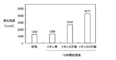
図1は、化学発光法(ケミカルルミネッセンス)による布に付着させた物質の酸化度合いを示す図である。 FIG. 1 is a diagram showing the degree of oxidation of a substance attached to a cloth by a chemiluminescence method (chemical luminescence).
図1に示すように、照射するイオン数が多いほど、発光強度が大きくなっている。縦軸としては、化学発光に伴う光電子増倍管のカウント数としているが、上述の通り、このカウント数は、付着させたリノール酸の酸化度合いを反映している。試験布に照射するイオン濃度と正の相関をもって、ケミカルルミネッセンスの発光強度が増大する。すなわち、イオンの照射により、布に付着した物質(リノール酸)の酸化反応が進行していることを示している。また、イオン発生素子を作動させずに送風のみとした場合においては、12時間経過後もケミカルルミネッセンス発光強度はほとんど変化しておらず、イオンが存在しない場合においては、リノール酸の酸化反応は生じないことがわかった。 As shown in FIG. 1, the emission intensity increases as the number of irradiated ions increases. The vertical axis represents the photomultiplier tube count associated with chemiluminescence. As described above, this count reflects the degree of oxidation of the attached linoleic acid. The emission intensity of chemical luminescence increases with a positive correlation with the ion concentration irradiated onto the test cloth. That is, it shows that the oxidation reaction of the substance (linoleic acid) adhering to the cloth is proceeding by ion irradiation. In addition, when only the air is blown without operating the ion generating element, the chemical luminescence intensity is hardly changed even after 12 hours, and in the absence of ions, the oxidation reaction of linoleic acid occurs. I knew it was n’t there.
以上のように、本願の発明者は、イオンが衣類や布類に付着させた物質を酸化分解することを確認した。 As described above, the inventors of the present application have confirmed that the ions oxidatively decompose the substance attached to clothing and cloth.
(検証実験3)
次に、イオンの衣類や布類に付着したニオイに対する除去特性のイオン濃度依存性を評価した。
(Verification experiment 3)
Next, the ion concentration dependency of the removal property of the ions on odors attached to clothing and cloth was evaluated.
まず、JIS標準布(ポリエステル(商品コード:670110))を試験布として、市販の洗剤で洗濯して、10cm×10cm=100cm2の大きさにカットし、10枚を1まとめとして酢酸10mgを付着させた。試験布1枚当たりには、酢酸1mgを付着した。この試験布を1m3の試験ボックス内に吊るして送風しながら2時間、放置した。試験布は、以下の(1)〜(5)の条件で放置された。(2)〜(5)の条件では、イオン発生素子を駆動し、試験布をイオンに2時間暴露した。その後、試験布をアルミパックに密封して60℃にて30分間放置し、その後に試験布から再放出する酢酸量を測定した。なお酢酸濃度の測定は、株式会社ガステックの検知管NO.81L(0.488μgの識別が可能)を用いて行なった。 First, JIS standard cloth (polyester (product code: 670110)) is used as a test cloth, washed with a commercially available detergent, cut into a size of 10 cm × 10 cm = 100 cm 2 , and 10 sheets of acetic acid are attached together as 10 sheets. I let you. 1 mg of acetic acid adhered to each test cloth. This test cloth was suspended in a 1 m 3 test box and left for 2 hours while blowing air. The test cloth was left under the following conditions (1) to (5). Under the conditions (2) to (5), the ion generating element was driven and the test cloth was exposed to ions for 2 hours. Thereafter, the test cloth was sealed in an aluminum pack and allowed to stand at 60 ° C. for 30 minutes, and then the amount of acetic acid re-released from the test cloth was measured. In addition, the measurement of acetic acid concentration was performed using a detector tube NO. 81L (0.488 μg can be identified) was used.
(1)イオン発生なし
(2)イオン濃度5000個/cm3
(3)イオン濃度10000個/cm3
(4)イオン濃度25000個/cm3
(5)イオン濃度88000個/cm3
すなわち、イオン濃度の異なる5条件でのニオイの除去特性を評価する。
(1) No generation of ions (2)
(3) Ion concentration 10,000 / cm 3
(4)
(5)
That is, the odor removal characteristics under five conditions with different ion concentrations are evaluated.
図2は、試験布の酢酸再放出量の濃度依存性を示す図(A)と、イオンを照射せずに送風を行なった試験布の酢酸再放出量から、各イオン濃度の雰囲気下で送風を行なったときの試験布の酢酸再放出量を引いて求めた酢酸再放出の減少量の濃度依存性を示す図(B)である。 FIG. 2 is a graph (A) showing the concentration dependence of the acetic acid re-release amount of the test cloth and the acetic acid re-release amount of the test cloth that was blown without irradiating the ions. It is a figure (B) which shows the density | concentration dependence of the reduction | decrease amount of acetic acid re-release calculated | required by subtracting the acetic acid re-release amount of a test cloth when performing.
図2の(A)に示すように、イオンを照射しながら送風された試験布から再放出される酢酸の量は、照射したイオンの濃度が高いほど、少なくなった。この結果から、上記の正イオンと負イオンは、酢酸の再放出を抑えて、酢酸の臭気成分が試験布から脱離してニオイを生じさせることを防ぐことができることがわかった。すなわち、上記正イオンと負イオンは、酢酸の付着臭に対する除去効果を有することがわかった。 As shown in FIG. 2A, the amount of acetic acid re-released from the test cloth blown while irradiating with ions decreased as the concentration of irradiated ions increased. From this result, it was found that the above positive ions and negative ions can suppress the re-release of acetic acid and prevent the odor component of acetic acid from detaching from the test cloth and causing odor. That is, it has been found that the positive ions and the negative ions have a removing effect on the attached odor of acetic acid.
また、図2の(B)に示すように、試験布に照射したイオンの濃度と酢酸再放出の減少量が正の相関となっていることから、酢酸付着臭の除去効果がイオンの作用によることがわかる。 Further, as shown in FIG. 2B, since the concentration of ions irradiated on the test cloth and the reduction amount of acetic acid re-release are positively correlated, the effect of removing acetic acid adhering odor is due to the action of ions. I understand that.
図3は、試験布に付着している0.1mgの酢酸を除去するために必要な時間のイオン濃度依存性を示す図である。図3の(A)では、縦軸の所要時間を対数表示して示し、図3の(B)では、図3の(A)に示す結果を、所要時間0〜2.5の範囲だけ拡大して示す。
FIG. 3 is a graph showing the ion concentration dependence of the time required to remove 0.1 mg of acetic acid adhering to the test cloth. In FIG. 3A, the required time on the vertical axis is shown logarithmically, and in FIG. 3B, the result shown in FIG. 3A is expanded by the range of required
図3の(A)と(B)に示すように、試験布に付着している0.1mgの酢酸を除去するために必要な時間は、イオン濃度が高くなるに従って、短縮される。例えば、イオン濃度が38万個の場合には、0.017時間、すなわち、約1分間で試験布に付着した0.1mgの酢酸を除去することができることがわかった。 As shown in FIGS. 3A and 3B, the time required to remove 0.1 mg of acetic acid adhering to the test cloth is shortened as the ion concentration increases. For example, when the ion concentration is 380,000, it was found that 0.1 mg of acetic acid attached to the test cloth can be removed in 0.017 hours, that is, about 1 minute.
以上の検証実験1〜3の結果から、化学的に相互作用してH2O2やOHラジカルを生じさせる正イオンとしてH+(H2O)m(mは自然数)と負イオンとしてO2 −(H2O)n(nは自然数)は、衣類や布類等の対象物に付着している臭気成分を酸化分解することによって、対象物のニオイを除去することが確認された。
From the results of the
すなわち、イオン発生素子からは正イオンとしてH+(H2O)mと、負イオンとしてO2 −(H2O)nとが発生する。発生した正イオンと負イオンの相互作用により、・OHが生成される(化学式(1)〜(3))。この・OHが、臭気成分、すなわち、ニオイのもととなる有機化合物のC−C結合、C=C結合及びC=O結合等に作用して、これらの結合を分解することによって、消臭効果が得られる。以下に、代表的なニオイのもととなる物質の・OHによる分解作用を化学式で示す。 That is, the ion generating element generates H + (H 2 O) m as positive ions and O 2 − (H 2 O) n as negative ions. OH is generated by the interaction between the generated positive ions and negative ions (chemical formulas (1) to (3)). This OH acts on the odor component, that is, the C—C bond, C═C bond, C═O bond, etc. of the organic compound that is the source of odor, thereby decomposing these bonds, thereby eliminating the odor An effect is obtained. In the following, the chemical action of the decomposition action of .OH on a typical odor source is shown.
酢酸の分解:
CH3COOH+8・OH → 2CO2+6H2O …(4)
アセトアルデヒドの分解:
CH3CHO+10・OH → 2CO2+7H2O …(5)
従来の空気調和機や空気清浄機のように、空気調和対象空間内に存在する粒子を不活化する目的で正イオンとしてH+(H2O)mと、負イオンとしてO2 −(H2O)nとを発生させる場合、比較的広い空間内にイオンを発生させることになるので、空気調和対象空間のイオン濃度は10000個/cm3程度となる。
Decomposition of acetic acid:
CH 3 COOH + 8 · OH → 2CO 2 + 6H 2 O (4)
Decomposition of acetaldehyde:
CH 3 CHO + 10 · OH → 2CO 2 + 7H 2 O (5)
Like conventional air conditioners and air purifiers, H + (H 2 O) m as positive ions and O 2 − (H 2 as negative ions for the purpose of inactivating particles existing in the air conditioning target space. O) When n is generated, ions are generated in a relatively wide space, so that the ion concentration in the air-conditioning target space is about 10,000 / cm 3 .
一方、衣類や布類に付着したニオイを除去する目的で正イオンとしてH+(H2O)mと、負イオンとしてO2 −(H2O)nとを発生させるのであれば、空気調和機や空気清浄機を用いて空気調和対象空間にイオンを放出する場合と比較して小さな領域にイオンを照射することとなるので、イオン濃度が高い環境を達成することが可能である。イオン濃度が高くなれば、検証実験3の結果に示すとおり、試験布等の対象物に付着したニオイに対する除去特性が向上する。
On the other hand, the H + (H 2 O) m as positive ions in order to remove the odor adhering to the clothing and textiles, O 2 as a negative ion - if (H 2 O) is to generate an n, air conditioning Compared with the case where ions are emitted into the air-conditioning target space using a vacuum cleaner or an air purifier, ions are irradiated onto a small area, so that an environment with a high ion concentration can be achieved. If the ion concentration is increased, as shown in the result of the
図3に示すように、イオンを衣類や布類等の対象物に直接、照射する場合においては、イオン濃度を10万個/cm3以上にすることにより、付着したニオイに対する除去特性が大幅に向上する。イオン濃度を10万個/cm3以上の状態として衣類や布類に照射するためには、正イオンと負イオンを発生する発生素子と、衣類や布類との距離を1m以内にすることが望ましい。 As shown in FIG. 3, in the case of directly irradiating an object such as clothing or cloth with ions, by making the ion concentration to be 100,000 / cm 3 or more, the removal characteristic for the attached odor is greatly improved. improves. In order to irradiate clothing and cloth with an ion concentration of 100,000 ions / cm 3 or more, the distance between the generating element generating positive ions and negative ions and the clothes or cloth should be within 1 m. desirable.
このような考察に基づいて、以下に本発明の実施形態を説明する。 Based on such considerations, embodiments of the present invention will be described below.
(第1実施形態)
図4は、この発明の第1実施形態として、ブラシの全体を示す正面図(A)と、図4の(A)に示すブラシをB−B線で示す方向から見たときの断面図(B)と、図4の(A)に示すブラシを矢印Cで示す方向から見たときの底面図(C)である。図4の(B)では、イオン発生素子よりも取手側に植え付けられている毛の図示を省略している。
(First embodiment)
FIG. 4 shows a front view (A) showing the entire brush as a first embodiment of the present invention, and a sectional view when the brush shown in FIG. 5B is a bottom view (C) when the brush shown in FIG. 4A is viewed from the direction indicated by the arrow C. FIG. In FIG. 4B, illustration of the hair planted on the handle side with respect to the ion generating element is omitted.
図4の(A)〜(C)に示すように、付着物除去具としてブラシ1は、板状の本体101と、本体101と連結されている取手102と、本体101の一方の面上に植え付けられている付着物剥離部材として毛110と、本体101に植え付けられている毛110に囲まれるようにして本体101の一方の面上に配置されているイオン発生部としてイオン発生素子130とイオン発生素子130の駆動手段とから構成されている。取手102は、本体101と一体に形成されていてもよい。
As shown in FIGS. 4A to 4C, the
ブラシ1の本体101は、木材や樹脂から形成されている。毛110は、繊維状の獣毛や植物毛や樹脂毛である。
The
毛110は、本体101の一方の面において、所定の領域としてほぼ長方形の滞留領域120を形成するように植え付けられている。多数の毛110のうち、滞留領域120を形成する毛111は滞留領域形成部の一例である。イオン発生素子130は、滞留領域120内に配置されている。イオン発生素子130は、プラズマ放電現象を用いた電気的手法によって正イオンと負イオンとを発生させる。
The
図5は、ブラシが備えるイオン発生素子の全体を示す斜視図(A)と、イオン発生素子の本体の内部を示す斜視図(B)と、図5の(B)に示すイオン発生素子の内部をC−C線の方向から見たときの断面図(C)である。 FIG. 5 is a perspective view (A) showing the whole of the ion generating element provided in the brush, a perspective view (B) showing the inside of the main body of the ion generating element, and the inside of the ion generating element shown in (B) of FIG. It is sectional drawing (C) when seeing from the direction of CC line.
図5の(A)に示すように、イオン発生素子130は、扁平な略直方体形に形成されている合成樹脂製の本体131に収容されている。イオン発生素子130の本体131には、幅広の一面に略円形の2つの開口132が長手方向に並べて形成されている。イオン発生素子130は、2つの開口132の一方から正イオンを放出し、他方から負イオンを発生させる。また、本体131の一側面には、イオン発生素子130が動作するための高電圧が供給される金属製の端子部133が設けられている。イオン発生素子130の概略寸法は7cm×2cm×1cm程度の大きさである。
As shown in FIG. 5A, the
図5の(B)と(C)に示すように、イオン発生素子130は、本体131内に基板134と、この基板134に設けられた正イオン発生部として正電極135と、負イオン発生部として負電極136及び接地電極137とを備えている。基板134は略矩形の板体であり、絶縁物質で構成されている。正電極135と負電極136は、先端部分が先鋭に尖らせられた丸棒状の電極である。正電極135と負電極136は、基板134に形成された2つの貫通孔134aにそれぞれ通されて、基板134の一面に突出させ、半田または接着剤等を用いて基板134に固定されている。
As shown in FIGS. 5B and 5C, the
接地電極137は、基板134より表面積が若干小さい板状の電極であり、基板134に対向するように、基板134から所定間隔を隔てて基板134に固定されている。基板134に対する接地電極137の固定は、接地電極137の四方に延出して設けられた4つの脚部137a(図5の(B)には3つの脚部137aのみ図示している)を略直角に屈曲し、基板134に形成された4つの貫通孔134bに接地電極137の4つの脚部137aをそれぞれ挿通して、半田または接着剤等により脚部137aを固定することで行われる。
The
接地電極137には、2つの略円形の開口137bが形成されている。接地電極137が基板134に固定された場合、正電極135及び負電極136は接地電極137の開口137bの略中心の位置に固定される。接地電極137の開口137bの縁部137cは、基板134側へ向けて折り曲げてある。正電極135、負電極136及び接地電極137を基板134に固定して本体131に収容した場合には、本体131に形成された2つの開口132と、接地電極137に形成された2つの開口137bとが略同心に配されるようにしてある。
The
イオン発生素子130の接地電極137は接地電位に接続され、正電極135には正極の高電圧が印加され、負電極136には負極の高電圧が印加される。正電極135及び負電極136にそれぞれ高電圧が印加されると、接地電極137の開口137bの縁部137cが強電界になり、接地電極137からプラズマ放電が発生する。プラズマ放電により空気中の酸素及び水蒸気が電離してイオンが発生する。なお、電極の構造及び印加電圧の最適化により、有害物質とされるオゾンの発生を極力抑えるように制御を行っている。このときに最も安定して発生するイオンは、正イオンのH+(H2O)mと負イオンのO2 −(H2O)nとである。発生するイオンの質量分析などを行って解析した結果、これら以外のイオンの発生はほとんど確認されていない。イオン発生素子130の本体131に形成された2つの開口132のうち、正電極135が設けられた開口132から正イオンH+(H2O)mが放出され、負電極136が設けられた開口132から負イオンO2 −(H2O)nが放出される。
The
上述の通り、イオン発生素子で発生したH+(H2O)mとO2 −(H2O)nのイオンは、化学反応して活性種であるH2O2または・OH(OHラジカル)を生成する。上述の検証実験1〜3に示すように、H2O2または・OHは、極めて強力な活性を示すため、衣類や布類に付着したニオイを除去することができる。そのため、正イオンと負イオンの両方を発生させて照射させる。負イオン単独の放出の場合、相互作用が発生しないので、化学反応して活性種であるH2O2または・OH(OHラジカル)が生成しない。そのため、付着したニオイに対する除去特性は非常に小さいものとなる。
As described above, the ions of H + (H 2 O) m and O 2 − (H 2 O) n generated in the ion generating element chemically react with each other to form an active species of H 2 O 2 or .OH (OH radical). ) Is generated. As shown in the above-described
図4の(B)に示すように、ブラシ1の毛110が対象物として衣類300に接するように、使用者が取手102を持ってブラシ1を保持すると、衣類300の表面と、毛111と、イオン発生素子130と、本体101において毛110が植え付けられている面とによって滞留領域120が囲まれる。毛110によって衣類300から剥離される付着物は、滞留領域120内に滞留する。イオン発生素子130で発生される正イオンと負イオンも、滞留領域120内に滞留する。
As shown in FIG. 4B, when the user holds the
滞留領域120内では、正イオンと負イオンとが、衣類300から剥離された塵埃等の付着物の表面上で化学的に相互作用して、付着物のニオイを除去する。また、正イオンと負イオンは、衣類300の表面上でも化学的に相互作用して、衣類300の表面に付着したまま、毛110によって剥離されなかった臭気物質を分解し、衣類300のニオイを除去する。
In the staying
以上のように、第1実施形態のブラシ1は、衣類300に付着している付着物を衣類300から剥離させるための毛110と、正イオンとしてH+(H2O)m(mは任意の自然数)と負イオンとしてO2 −(H2O)m(mは任意の自然数)とを発生させるイオン発生素子130と、イオン発生素子130から放出された正イオンと負イオンと毛110によって衣類300から剥離された付着物とを衣類300の表面上に形成される滞留領域120内に滞留させるための毛111とを備える。
As described above, the
衣類300に付着している塵埃や汚れ、花粉、臭気を発生させる臭気物質等の付着物は、毛110によって衣類300から物理的に剥離される。
Deposits such as dust, dirt, pollen, and odorous substances that generate odor are physically peeled from the
毛110によって衣類300から剥離された付着物は、イオン発生素子130から放出された正イオンと負イオンとともに、毛111によって衣類300の表面上の滞留領域120内に滞留させられる。このようにして、正イオンと負イオンは、分散することなく、濃度を保ったままで衣類300の表面上の滞留領域120内に滞留させられる。衣類300から剥離された付着物と正イオンと負イオンとは、滞留領域120内に滞留させられることによって、互いに衝突しやすくなる。
The deposits peeled off from the
また、正イオンと負イオンは、分散せずに衣類300の表面上に形成される滞留領域120内に滞留させられることによって、衣類300の表面に接触したり、衣類300の表面から衣類300の内部に入り込んだりしやすくなる。このようにして、毛110によって剥離されず、衣類300の表面や内部に残っている臭気成分等の付着物にも正イオンと負イオンが接触しやすくなる。
Further, the positive ions and the negative ions are retained in the retaining
衣類300から剥離された付着物や、衣類300の表面や内部に残っている付着物が正イオンと負イオンと衝突すると、付着物と正イオンと負イオンとが相互作用する。付着物が臭気を発生させる臭気物質である場合には、臭気物質が正イオンと負イオンと相互作用することによって分解される。このようにして、化学的な作用を利用して、衣類300から剥離された付着物が脱臭される。
When the deposits peeled off from the
以上のように、第1実施形態のブラシ1は、毛110によって衣類300から物理的に付着物を剥離するとともに、正イオンと負イオンの濃度を保持したままで、衣類300の表面上に形成された滞留領域120内に付着物とともに滞留させて、正イオンと負イオンと付着物との化学的な相互作用によって付着物を脱臭する。
As described above, the
このようにすることにより、効果的に付着物のニオイを除去することが可能なブラシ1を提供することができる。
By doing in this way, the
また、第1実施形態のブラシ1においては、毛111は、イオン発生素子130を囲むように、毛110の一部によって形成されている。
In the
このように、毛111がイオン発生素子130を囲むように形成されているので、イオン発生素子130で発生した正イオンと負イオンを分散させにくく、正イオンと負イオンの濃度を保持しやすくなる。また、毛111が毛110によって形成されていることによって、毛110によって衣類300から剥離された付着物が分散される前に、付着物を正イオンと負イオンとともに滞留領域120内に滞留させることができる。
Thus, since the
また、第1実施形態のブラシ1においては、正電極135と負電極136とが別個に形成されている。そこで、正電極135と負電極136のそれぞれに印加する電圧の大きさや波形を異なるようにすることによって、正電極135で発生される正イオンの量と、負電極136で発生される負イオンの量を異ならせることができる。
Moreover, in the
衣類や布類等の対象物は、特に、湿度の低い環境においては、帯電していることがある。対象物を帯電させる静電気の極性が正となるか負となるかは、物質の種類によりある程度はきまっており、帯電列と呼ばれる規則に従う。繊維など電気的絶縁体の帯電符号に関する法則として帯電列がある。帯電は衣類や布類での表面現象であるため、試料差や表面の粗さ、測定方法や環境条件によって影響を受けるが、古くから報告されている帯電列の間には比較的によい再現性がある。すなわち、正になる傾向が強い順に並べると、ガラス、ナイロン、羊毛、レーヨン、綿、絹、ポリエステル、アセテート、アクリル、金属、ポリスチレン、ポリプロピレン、ポリエチレン、ポリ塩化ビニリデン、となっている(繊維便覧 第2版 繊維学会編 丸善株式会社)。 Objects such as clothing and cloth may be charged, particularly in an environment with low humidity. Whether the polarity of static electricity that charges an object is positive or negative depends on the type of the substance, and follows a rule called a charge train. There is a charge train as a law relating to a charge sign of an electrical insulator such as a fiber. Since charging is a surface phenomenon in clothing and fabrics, it is affected by sample differences, surface roughness, measurement methods, and environmental conditions, but it has a relatively good reproduction between the charged columns that have been reported for a long time. There is sex. In other words, glass, nylon, wool, rayon, cotton, silk, polyester, acetate, acrylic, metal, polystyrene, polypropylene, polyethylene, and polyvinylidene chloride are listed in order of strong positive tendency. 2nd edition, Textile Society, Maruzen Co., Ltd.).
特に、一般家庭で衣類や布類の中では、ポリエステル系の合成繊維が使われている。ポリエステル系の合成繊維は、冬場の乾燥した状況においては、表面が負に帯電する傾向が強く(人間が正に帯電する)、静電気が発生する。 In particular, polyester-based synthetic fibers are used in clothing and fabrics in general households. Polyester-based synthetic fibers tend to be negatively charged on the surface in a dry state in winter (humans are positively charged) and generate static electricity.
衣類や布類等の対象物の表面に電荷が存在すると、イオンによるニオイの除去効果が低下する場合がある。 If there is a charge on the surface of an object such as clothing or cloth, the effect of removing odors by ions may be reduced.
上述のように、対象物に付着したニオイは、対象物に照射された正イオンと負イオンとが化学反応してH2O2やOHラジカルを生成することによって、分解されて除去される。そのため、イオンによるニオイの除去効果が最も大きくなるのは、正イオンと負イオンとが同量ずつ対象物に照射される場合である。 As described above, the odor adhering to the object is decomposed and removed by the chemical reaction between the positive ions and the negative ions irradiated on the object to generate H 2 O 2 and OH radicals. For this reason, the odor removal effect by the ions is greatest when the object is irradiated with the same amount of positive ions and negative ions.
正イオンと負イオンとを同量ずつ対象物に照射しても、対象物が静電気で帯電していると、照射したイオンと対象物表面の静電気とが中和して、イオンが失活してしまう。対象物の表面が正に帯電しているときには、正イオンと負イオンとを同量ずつ対象物に照射しても、負イオンが対象物の表面の負電荷と中和してしまい、正イオンに対して負イオンの割合が減少する。対象物の表面が負に帯電しているときには、正イオンと負イオンとを同量ずつ対象物に照射しても、正イオンが対象物の表面の負電荷と中和してしまい、負イオンに対して正イオンの割合が減少する。このように、正イオンと負イオンとを同量ずつ対象物に照射しても、正イオンと負イオンの一方が他方よりも少なくなると、H2O2やOHラジカルを生成する割合が減少し、対象物に照射された正イオンと負イオンのすべてが互いに化学反応する場合と比較すると、衣類や布類に付着したニオイに対する除去効果が低下する。 Even if the target is irradiated with the same amount of positive ions and negative ions, if the target is charged with static electricity, the irradiated ions and static electricity on the surface of the target are neutralized, and the ions are deactivated. End up. When the surface of the object is positively charged, even if the object is irradiated with the same amount of positive ions and negative ions, the negative ions are neutralized with the negative charge on the surface of the object. The proportion of negative ions is reduced. When the surface of the object is negatively charged, even if the object is irradiated with the same amount of positive ions and negative ions, the positive ions are neutralized with the negative charge on the surface of the object. The proportion of positive ions decreases with respect to. As described above, even when the object is irradiated with the same amount of positive ions and negative ions, if one of the positive ions and the negative ions is smaller than the other, the ratio of generating H 2 O 2 and OH radicals decreases. Compared with the case where all of the positive ions and negative ions irradiated to the object chemically react with each other, the effect of removing odors attached to clothes and fabrics is reduced.
そこで、第1実施形態のブラシ1においては、正電極135と負電極136に印加する電圧の大きさや波形を異ならせて、正電極135で発生される正イオンの量と、負電極136で発生される負イオンの量を異ならせて、衣類や布類の表面に存在する静電気を除去してもよい。
Therefore, in the
上述のように、特に冬場には、ポリエステルやアクリルといった化学繊維で形成されている衣類や布類等の対象物の表面には負電荷が帯電しやすい。そこで、例えば、冬場には、正電極135に印加する電圧を負電極136に印加する電圧よりも大きくして、正電極135で発生される正イオンの量が、負電極136で発生される負イオンの量よりも多くなるようにする。正イオンは、対象物の表面に帯電している負電荷と中和して失活してしまうが、正イオンの方が負イオンよりも多く発生されているので、対象物の表面の静電気と中和しない負イオンを効率よく化学反応に用いることができる。
As described above, particularly in winter, negative charges are likely to be charged on the surface of an object such as clothing or cloth formed of chemical fibers such as polyester or acrylic. Therefore, for example, in winter, the voltage applied to the
また、例えば、ブラシ1を使用する前に、対象物の帯電状態をセンシングして、対象物の帯電状態に合わせて正イオンと負イオンの発生割合を調節してもよい。あらかじめ対象物の帯電状態をセンシングして、対象物の帯電極性と逆の極性のイオンを、対象物の帯電極性と同じ極性のイオンよりも多く発生させることによって、発生させられたイオンを効率よくニオイの除去に利用することができる。このようにして、正イオンと負イオンの相乗効果を最も高くすることができる。
Further, for example, before using the
以上のように、第1実施形態のブラシ1においては、イオン発生素子130は、正イオンを発生させるための正電極135と、負イオンを発生させるための負電極136とを含み、正電極135と負電極136とは別個に形成されている。
As described above, in the
このようにすることにより、正電極135と負電極136とに別々に電圧を印加して、正イオンの発生量と、負イオンの発生量とをそれぞれ調節することができる。
By doing so, it is possible to adjust the generation amount of positive ions and the generation amount of negative ions by separately applying voltages to the
なお、第1実施形態においては、付着物除去具としてブラシについて説明したが、本発明の付着物除去具は、毛の短いエチケットブラシ、歯ブラシ、モップ、食器用スポンジ、くつ拭きマット、足拭きマット、タオル、洗濯機等に適用されてもよい。 In addition, in 1st Embodiment, although the brush was demonstrated as an attachment removal tool, the attachment removal tool of this invention is a short hair etiquette brush, a toothbrush, a mop, a sponge for tableware, a shoe wiping mat, a foot wiping mat. It may be applied to towels, washing machines and the like.
例えば、衣類として洗濯物を洗浄槽に収容して洗浄槽を水平方向から傾いた面内で回転させる洗濯機の場合には、洗浄槽内に配置されるバッフルが付着物剥離部材の一例である。洗濯機は、洗濯物に付着している付着物を洗濯物から剥離させるためのバッフルと回転可能な洗浄槽と、正イオンとしてH+(H2O)m(mは任意の自然数)と負イオンとしてO2 −(H2O)n(nは任意の自然数)とを発生させるイオン発生素子130と、イオン発生素子130から放出された正イオンと負イオンとバッフルと洗浄槽によって洗濯物から剥離された付着物とを洗濯物の表面上に形成される所定の領域内に滞留させるための洗浄槽とを備えることによって、この発明の付着物除去具としての効果を奏することができる。
For example, in the case of a washing machine that stores laundry in a washing tub as clothing and rotates the washing tub in a plane inclined from the horizontal direction, a baffle disposed in the washing tub is an example of the deposit peeling member. . The washing machine has a baffle and a rotatable washing tub for separating the adhering matter adhering to the laundry, and a positive ion of H + (H 2 O) m (m is an arbitrary natural number) and negative.
(第2実施形態)
図6は、この発明の第2実施形態として、ブラシの全体を示す正面図(A)と、図6の(A)に示すブラシをB−B線で示す方向から見たときの断面図(B)と、図6の(A)に示すブラシを矢印Cで示す方向から見たときの底面図(C)である。図6の(B)では、イオン発生素子よりも取手側に植え付けられている毛の図示を省略している。
(Second Embodiment)
FIG. 6 shows a front view (A) showing the entire brush as a second embodiment of the present invention, and a cross-sectional view of the brush shown in FIG. 7B is a bottom view when the brush shown in FIG. 6A is viewed from the direction indicated by the arrow C. FIG. In FIG. 6B, illustration of hairs planted closer to the handle side than the ion generating element is omitted.
図6に示すように、第2実施形態のブラシ2が第1実施形態のブラシ1と異なる点としては、ブラシ2は、複数のイオン発生素子140a,140b,140cによって構成されるイオン発生部140を備える。イオン発生素子140a,140b,140cは、一列に並べて配置されている。また、イオン発生素子140aとイオン発生素子140bとの間、イオン発生素子140bとイオン発生素子140cとの間にそれぞれ配置される隔壁として仕切り板150を備える。仕切り板150の端部は、イオン発生部140よりも2mm以上、突出していることが望ましい。
As shown in FIG. 6, the
イオン発生部140を構成するそれぞれのイオン発生素子140a,140b,140cは、第1実施形態のブラシ1が備えるイオン発生素子130(図5)と同様に構成されているが、電極は1本だけである点においてイオン発生素子130と異なっている。
Each
イオン発生素子140a,140b,140cは、それぞれ、印加される電圧の極性に応じて、正イオンまたは負イオンのいずれか一方を発生させる。例えば、イオン発生素子140aで正イオン、イオン発生素子140bで負イオン、イオン発生素子140cで正イオンを発生させるように駆動される。
The
ブラシ2の毛110が対象物として衣類300に接するように、使用者が取手102を持ってブラシ2を保持すると、衣類300の表面と、毛111と、イオン発生素子140a,140b,140cと、本体101において毛110が植え付けられている面とによって滞留領域120が囲まれる。毛110によって衣類300から剥離される付着物は、滞留領域120内に滞留する。イオン発生素子140a,140b,140cで発生される正イオンと負イオンも、滞留領域120内に滞留する。
When the user holds the
滞留領域120内では、正イオンと負イオンとが、衣類300から剥離された塵埃等の付着物の表面上で化学的に相互作用して、付着物のニオイを除去する。また、正イオンと負イオンは、衣類300の表面上でも化学的に相互作用して、衣類300の表面に付着したまま、毛110によって剥離されなかった臭気物質を分解し、衣類300のニオイを除去する。
In the staying
正イオンを発生する電極と負イオンを発生する電極とが近くに配置されている場合、それぞれの電極から放出された正イオンと負イオンとが互いに近付きやすく、中和失活してしまうことがある。正イオンと負イオンが中和失活してしまうと、対象物の表面においてニオイを除去するために必要な相互作用に用いられる正イオンと負イオンの割合が減少してしまう。 When an electrode that generates positive ions and an electrode that generates negative ions are arranged close to each other, the positive ions and negative ions released from the respective electrodes are likely to approach each other and neutralize and deactivate. is there. If the positive ions and the negative ions are neutralized and deactivated, the ratio of the positive ions and the negative ions used for the interaction necessary for removing odors on the surface of the object decreases.
正イオンと負イオンのいずれも、電極の近傍で最もイオン濃度が高いので、電極の近傍において最も中和失活しやすい。 Since both the positive ion and the negative ion have the highest ion concentration in the vicinity of the electrode, they are most easily neutralized and deactivated in the vicinity of the electrode.
そこで、正イオンを発生するイオン発生素子140aとイオン発生素子140cと、負イオンを発生するイオン発生素子140bとの間を仕切り板150で区切ることにより、イオン発生素子140a,140b,140cで発生された直後の高濃度の正イオンと負イオンとが近付きにくくなる。このようにして、正イオンと負イオンの再結合による中和失活の度合を低減することができる。
Therefore, the
イオン発生素子140a,140b,140cは、衣類300の帯電状態等に応じて、次の(1)〜(4)に示すイオンを発生させるように駆動されてもよい。
The
(1)イオン発生素子140aで正イオン発生、イオン発生素子140bで負イオン発生、イオン発生素子140cで正イオン発生
(2)イオン発生素子140aで正イオン発生、イオン発生素子140bで正イオン発生、イオン発生素子140cで負イオン発生
(3)イオン発生素子140aで負イオン発生、イオン発生素子140bで正イオン発生、イオン発生素子140cで負イオン発生
(4)イオン発生素子140aで負イオン発生、イオン発生素子140bで負イオン発生、イオン発生素子140cで正イオン発生
上記の(1)〜(4)のようにイオンを発生させる場合には、イオン発生素子140a,140b,140cのそれぞれにおいて発生されるイオンの量が等しい場合には、イオン発生部140全体としては、発生される正イオンと負イオンは同量にならない。このように、意図的にイオン発生量のバランスを崩すことによって、イオン発生素子140a,140b,140cのそれぞれにおいて発生されるイオンの量が等しくても、衣類300の表面の帯電を除電してから、正イオンと負イオンを照射することができる。
(1) Generation of positive ions by the
さらに、例えば、衣類300の表面の帯電状態をあらかじめセンシングして、ブラシ2のイオン発生素子140aとイオン発生素子140cによって発生されるイオンを、衣類300の帯電と反対の極性のイオンにしてもよい。このようにすることによって、使用者が取手102を持ってブラシ2を動かすとき、まず、衣類300の帯電と反対の極性のイオンが照射されて、衣類300の帯電がイオンによって中和される。その後、さらに正イオンと負イオンとが衣類300の表面に供給されるので、衣類300の表面において正イオンと負イオンとが効率よく相互作用してニオイの除去効果を発揮しやすくなる。
Furthermore, for example, the charged state of the surface of the
より具体的には、(1)イオン発生素子140aで正イオン、イオン発生素子140bで負イオン、イオン発生素子140cで正イオンを発生させる場合には、中央部に負イオン発生電極領域が存在し、周囲(両側)に正イオンを発生させる電極が存在している。したがって、この形態は、衣類300の表面が負に帯電した状態において用いられると、衣類300に付着したニオイを効果的に酸化分解により除去することができる。さらにこの形態においては、負イオン発生領域の両側のいずれの領域も正イオンを発生させる領域となっているために、本形態のブラシであれば、いずれの方向にブラシを動かしても(ブラッシング)、衣類300に最初に正イオンが照射されるため、付着したニオイを効果的に除去することができる。
More specifically, (1) in the case where positive ions are generated by the
また、(2)イオン発生素子140aで正イオン、イオン発生素子140bで正イオン、イオン発生素子140cで負イオンを発生させる場合には、正イオン発生領域の方が負イオン発生領域よりも大きくなっているので、衣類300が負に帯電している場合に用いられる形態である。さらに、両側のイオンの極性が正イオンと負イオンとなって、異なっている。そこで、この形態の場合には、衣類300の所定の位置に対して、正イオンが先に照射されるようにブラシを動かす(ブラッシングする)ことが好ましい。正イオン発生領域に続いて、正イオン発生領域と負イオン発生領域とが続くので、衣類や布類表面の負の帯電を正イオンにより中和失活することを実施してから、後に続く、正イオンと負イオンの相互作用により、付着したニオイを除去することができる。
(2) When generating positive ions in the
また、(3)イオン発生素子140aで負イオン、イオン発生素子140bで正イオン、イオン発生素子140cで負イオンを発生させる場合には、中央部に正イオン発生領域が存在し、周囲(両側)に負イオン発生領域が存在している。したがって、この形態は、衣類300の表面が正に帯電した状態において用いられると、衣類300に付着したニオイを効果的に酸化分解により除去することができる。さらにこの形態においては、両側のいずれの領域も負イオン発生電極となっているために、本形態のブラシであれば、いずれの方向にブラシを動かしても(ブラッシング)、衣類300に最初に負イオンが照射されるため、付着したニオイを効果的に除去することができる。
Further, (3) in the case where negative ions are generated by the
最後に、(4)イオン発生素子140aで負イオン、イオン発生素子140bで負イオン、イオン発生素子140cで正イオンを発生させる場合には、負イオン発生領域の方が正イオン発生領域よりも多くなっているので、衣類300が正に帯電している場合に用いられる形態である。さらに、両側のイオンの極性が正イオン発生電極と負イオン発生電極と異なっているため、この形態の場合、衣類や布類の所定の位置に対して、負イオンが先に照射されるようにブラシを動かす(ブラッシングする)ことが好ましい。負イオン発生領域に続いて、負イオン発生領域と正イオン発生領域が続くので、衣類300の正の帯電を負イオンにより中和失活してから、後に続く、正イオンと負イオンの相互作用により、衣類300に付着したニオイを除去することができる。
Finally, (4) when generating negative ions in the
以上のようにして、衣類や布類に付着したニオイを効果的に除去することができる。 As described above, odors attached to clothes and fabrics can be effectively removed.
なお、以上の説明においてはイオン発生素子140a,140b,140cの電極は、イオン発生素子130の正電極135と負電極136(図5)と同様、針型電極構造としているが、正イオン及び負イオンを独立して発生させるものであれば、プレート型電極であっても、その他の形状であってもかまわない。
In the above description, the electrodes of the
以上のように、第2実施形態のブラシ2においては、イオン発生部140は、正イオンを発生させるためのイオン発生素子と、負イオンを発生させるためのイオン発生素子とを含み、それぞれのイオン発生素子140a,140b,140cは別個に形成されている。
As described above, in the
このようにすることにより、イオン発生素子140a,140b,140cに別々に電圧を印加して、正イオンの発生量と、負イオンの発生量とをそれぞれ調節することができる。
By doing in this way, a voltage can be separately applied to
また、第2実施形態のブラシ2は、正電極と負電極とを隔てるように配置される仕切り板150を備える。
Moreover, the
このようにすることにより、正電極で発生した正イオンと負電極で発生した負イオンとが発生直後に衝突することを防いで、毛111によって形成される滞留領域120に到達する前に中和して失活してしまう正イオンと負イオンとを低減することができる。
By doing so, the positive ions generated at the positive electrode and the negative ions generated at the negative electrode are prevented from colliding immediately after the generation, and neutralized before reaching the
また、ブラシ2は、衣類300の帯電状態を検知するための検知手段を備えていてもよい。衣類300の帯電状態を検知する検知手段が、衣類が正に帯電しているとセンシングした場合には、負イオンの発生量を正イオンよりも多くして放出し、衣類が負に帯電しているとセンシングした場合には、正イオンの発生量を負イオンよりも多くして放出してもよい。
The
このようにすることにより、正イオンと負イオンを照射する衣類300が、たとえ正もしくは負に帯電している場合であっても、衣類300の帯電状態をあらかじめ検知した上で、衣類300の帯電によるイオン失活を考慮してイオンを照射することができる。このようにすることにより、衣類300の表面上では、正イオンと負イオンのバランスが調整されて、正イオンと負イオンによるニオイの除去効果を最大限に発揮させることができる。
In this way, even if the
第2実施形態のブラシ2のその他の構成と効果は、第1実施形態のブラシ1と同様である。
Other configurations and effects of the
次に、第2実施形態のブラシ2の他の形状として、正イオンを発生させるための電極と、負イオンを発生させるための電極を、それぞれ複数本配列する場合について説明する。
Next, as another shape of the
図7は、第2実施形態のブラシの他のひとつの形状のブラシの全体を模式的に示す斜視図である。 FIG. 7 is a perspective view schematically showing an entire brush of another shape of the brush according to the second embodiment.
図7に示すように、ブラシ3がブラシ2(図6)と異なる点としては、ブラシ3においては、イオン発生部140は、第1のイオン発生部141と第2のイオン発生部142とから構成され、第1のイオン発生部141と第2のイオン発生部142は、それぞれ、複数の針型電極141aと複数の針型電極142aによって構成されている。第1のイオン発生部141と第2のイオン発生部142は、並べて配置されている。複数の針型電極141aと複数の針型電極142aは、それぞれ複数の列に並べられている。また、ブラシ3においては、第1のイオン発生部141と第2のイオン発生部142との間に、隔離部材として仕切り板150が配置されている。
As shown in FIG. 7, the
また、ブラシ3は、衣類や布類等の対象物の表面の帯電状態を検知するための検知手段と、検知手段によって検知された帯電状態に基づいてイオン発生部140の駆動を制御する制御部を備える。検知手段としては、公知手法を用いることが可能であり、静電気測定器が各種販売されている。これらの静電気測定器においては、衣類や布類が帯電したときに形成される電界の大きさ、極性を測定することにより、帯電状態を把握することができる。
The
第1のイオン発生部141と第2のイオン発生部142は、それぞれ、印加される電圧の極性に応じて、正イオンまたは負イオンを発生させる。第1のイオン発生部141で発生させるイオンの極性と、第2のイオン発生部142で発生させるイオンの極性は、逆になるように、第1のイオン発生部141と第2のイオン発生部142に電圧を印加する。第1のイオン発生部141と第2のイオン発生部142は、それぞれ独立にイオン発生量を変化させることができる。例えば、第1のイオン発生部141と第2のイオン発生部142のいずれか一方のイオン発生量だけを増加させて、他方のイオン発生量を変化させないように、イオン発生部140の制御をすることができる。
The first
対象物に正イオンと負イオンを効果的に照射するために、さらに、より広い領域に、濃度を保ちながら正イオンと負イオンを照射するためには、複数本の針型電極141a,142aを配列してイオン発生部140を構成することが好ましい。ブラシ3が正イオンと負イオンを発生させるための電極を別個に備える場合には、少なくとも、それぞれ1本ずつ存在していればよい。しかしながら、正イオンと負イオンを発生させる針型電極は、それぞれ複数本ずつ存在する方が、イオン濃度の調節が容易となり、かつ、広範囲に正イオンと負イオンを放出させることができる。
In order to effectively irradiate a target with positive ions and negative ions, and to irradiate positive ions and negative ions over a wider area while maintaining the concentration, a plurality of needle-
また、このように、複数本の針型電極141a,142aを配列する場合には、正イオンを発生させる針型電極と負イオンを発生させる針型電極の領域を仕切り板150によって分けることが望ましい。
Further, in the case where a plurality of needle-
仕切り板150を設けるのは、逆の極性のイオンどうしが相互作用し合って中和失活してしまうことを防ぐためであるから、正イオンを発生させる針型電極どうしの間や、負イオンを発生させる針型電極どうしの間には、中和失活は発生しないので、仕切り板150を配置しなくてもよい。
The reason why the
使用者は、ブラシ3の取手102を持って、毛110が対象物の表面に接触するようにブラシ3を保持し、ブラシ3の駆動を開始させて、図7に矢印Pで示す方向にブラシ3を動かす。ブラシ3が駆動されると、まず、検知手段が対象物の帯電状態を検知する。一般的には、対象物がポリエステルやアクリルといった化学繊維で形成されている場合には、対象物は負に帯電する傾向が強い。例えば、このように、対象物が負に帯電していることを検知手段が検知した場合には、ブラシ3の移動方向Pに対して前方側に配置されている第1のイオン発生部141では正イオンを発生させ、ブラシ3の移動方向Pに対して後方側に配置されている第2のイオン発生部142では負イオンを発生させるように、制御部がイオン発生部140を制御する。
The user holds the
また、制御部は、ブラシ3の移動方向Pに対して前方側に配置されている第1のイオン発生部141で発生される正イオンの量を、ブラシ3の移動方向Pに対して後方側に配置されている第2のイオン発生部142で発生される負イオンの量よりも多くするように、イオン発生部140の駆動を制御する。
Further, the control unit determines the amount of positive ions generated by the first
イオンを多く発生させるためには、針型電極への印加電圧を高くしたり、針型電圧へ印加している電圧の波形を変える、すなわち、周波数を高くしたり、放電回数を多くしたりする手法を用いることができる。 To generate many ions, increase the voltage applied to the needle electrode, change the waveform of the voltage applied to the needle voltage, that is, increase the frequency or increase the number of discharges. Techniques can be used.
針型電極から多量に放出されたイオンのうち、対象物の表面の帯電によって、一部が除電、すなわち衣類の表面帯電との中和失活に用いられる。そして、除電に用いられなかったイオンと、その反対の極性のイオンの相互作用により、対象物に付着したニオイを除去することができる。 Of the ions released in large quantities from the needle-type electrode, a part of the ions is used for static elimination, that is, neutralization deactivation with the surface charge of the clothing due to the surface charge of the object. And the odor adhering to a target object can be removed by interaction of the ion which was not used for static elimination, and the ion of the opposite polarity.
従来の正イオンと負イオンを発生させる空気調和機や空気清浄機においては、一方のイオン(例えば正イオンとする)を発生する針型電極が複数本配列された領域と、他方のイオン(例えば負イオンとする)を発生する針型電極の領域からは、同量のイオンを発生させることが多かった。これは、同量の正イオンと負イオンを比較的広い空間に放出すると、空間内での正イオンと負イオンが同量となり、ウイルスや菌やアレルゲン成分を除去・不活化する効果が得られるためである。 In conventional air conditioners and air purifiers that generate positive ions and negative ions, a region where a plurality of needle-shaped electrodes that generate one ion (for example, positive ions) are arranged, and the other ion (for example, In many cases, the same amount of ions is generated from the region of the needle electrode that generates negative ions. This is because if the same amount of positive ions and negative ions are released into a relatively large space, the positive ions and negative ions in the space will be the same amount, and the effect of removing and inactivating viruses, fungi, and allergen components can be obtained. Because.
しかし、対象物にイオンを照射して、対象物の表面に付着したニオイを除去する目的でイオンを対象物の表面に供給する場合には、同量の正イオンと負イオンとを供給しても、はじめの対象物の表面の帯電状態により、正イオンと負イオンのバランスが崩れることがある。その結果、正イオンと負イオンとの相互作用の度合が低下し、対象物に付着したニオイを充分に除去できない場合がある。たとえば、対象物の表面が負に帯電している場合(化学繊維の場合)、正イオンと負イオンを同量として照射しても、正イオンは負イオンと比較して中和失活してしまう割合が多くなる。このままでは、対象物の表面においては、負イオンの濃度に対して、正イオンの濃度が少なくなるため、正イオンと負イオンの相互作用の度合が低下し、付着したニオイの除去特性が低下してしまうことがある。そこで、あらかじめ、対象物の表面での中和失活を想定して、正イオンの濃度を高めて放出させる。このようにすることにより、中和失活によって正イオンは減少するが、残った正イオンと負イオンの相互作用により、衣類や布類表面に付着したニオイを効果的に酸化分解により除去することができる。 However, when supplying ions to the surface of the object for the purpose of irradiating the object with ions and removing odors attached to the surface of the object, supply the same amount of positive ions and negative ions. However, the balance between positive ions and negative ions may be lost depending on the charged state of the surface of the first object. As a result, the degree of interaction between positive ions and negative ions decreases, and odors attached to the object may not be sufficiently removed. For example, when the surface of an object is negatively charged (in the case of chemical fibers), even if the same amount of positive ions and negative ions are irradiated, the positive ions are neutralized and deactivated compared to the negative ions. The ratio which ends up increases. If this is the case, the concentration of positive ions on the surface of the object will be less than the concentration of negative ions, so the degree of interaction between positive ions and negative ions will decrease, and the removal characteristics of attached odor will decrease. May end up. Therefore, assuming positive neutralization deactivation on the surface of the object, the positive ion concentration is increased and released in advance. By doing so, positive ions are reduced due to neutralization inactivation, but odors adhering to clothing and fabric surfaces are effectively removed by oxidative decomposition due to the interaction between the remaining positive ions and negative ions. Can do.
対象物の表面が正に帯電している場合には、逆に、第1のイオン発生部141で負イオンを発生させ、第2のイオン発生部142で正イオンを発生させ、かつ、負イオンを多く発生させるようにイオン発生部140の駆動を制御する。
Conversely, when the surface of the object is positively charged, negative ions are generated by the first
ブラシ3のその他の構成と効果は、ブラシ2と同様である。
Other configurations and effects of the
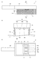
図8は、第2実施形態のブラシの他のもうひとつの形状のブラシの全体を模式的に示す斜視図である。 FIG. 8 is a perspective view schematically showing the whole of another brush having another shape according to the second embodiment.
図8に示すように、ブラシ4がブラシ2(図6)と異なる点としては、ブラシ4においては、イオン発生部140は、第1のイオン発生部141と第2のイオン発生部142と第3のイオン発生部143とから構成され、第1のイオン発生部141と第2のイオン発生部142と第3のイオン発生部143は、それぞれ、複数の針型電極141aと複数の針型電極142aと複数の針型電極143aによって構成されている。第1のイオン発生部141と第2のイオン発生部142と第3のイオン発生部143は、ブラシ4の移動方向Pに対して前方側から、第1のイオン発生部141、第2のイオン発生部142、第3のイオン発生部143の順に、一列に並べて配置されている。複数の針型電極141aと複数の針型電極142aと複数の針型電極143aは、それぞれ複数の列に並べられている。
As shown in FIG. 8, the
また、ブラシ3においては、第1のイオン発生部141と第2のイオン発生部142との間、第2のイオン発生部142と第3のイオン発生部143との間に、それぞれ、仕切り板150が配置されている。
In the
ブラシ4においては、一方のイオン(例えば正イオン)を発生する針型電極が複数本配列された領域と、他方のイオン(例えば負イオン)を発生する針型電極が複数本配列された領域にくわえて、一方のイオン(例えば正イオン)を発生する針型電極が複数本配列された領域の3領域となっている。
In the
ブラシ4のその他の構成と効果は、ブラシ2と同様である。
Other configurations and effects of the
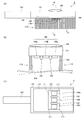
図9は、第2実施形態のブラシのさらに別の形状のブラシの全体を模式的に示す斜視図である。 FIG. 9 is a perspective view schematically showing an entire brush of still another shape of the brush according to the second embodiment.
図9に示すように、ブラシ5がブラシ2(図6)と異なる点としては、ブラシ5のイオン発生部140は、第1のイオン発生部141と第2のイオン発生部142と第4のイオン発生部144とから構成され、第1のイオン発生部141と第2のイオン発生部142と第4のイオン発生部144は、それぞれ、複数の針型電極141aと複数の針型電極142aと複数の針型電極144aによって構成されている。また、第4のイオン発生部144は、並べて配置される第1のイオン発生部141と第2のイオン発生部142の周囲を取り囲むように配置されている。複数の針型電極141aと複数の針型電極142aと複数の針型電極144aは、それぞれ複数の列に並べられている。
As shown in FIG. 9, the
また、ブラシ5においては、第1のイオン発生部141と第2のイオン発生部142との間、第1のイオン発生部141と第2のイオン発生部142と、第4のイオン発生部144との間に、それぞれ、仕切り板150が配置されている。
In the
ブラシ5のその他の構成と効果は、ブラシ2と同様である。
Other configurations and effects of the
図10は、第2実施形態のブラシのさらにまた別の形状のブラシとして、ブラシの全体を示す正面図(A)と、図10の(A)に示すブラシをB−B線で示す方向から見たときの断面図(B)と、図10の(A)に示すブラシを矢印Cで示す方向から見たときの底面図(C)である。図10の(B)では、イオン発生素子よりも取手側に植え付けられている毛の図示を省略している。 FIG. 10 is a front view (A) showing the entire brush as a brush of yet another shape of the brush of the second embodiment, and the direction shown by the line BB of the brush shown in FIG. It is sectional drawing (B) when it sees, and a bottom view (C) when the brush shown to (A) of FIG. In FIG. 10B, illustration of hairs planted closer to the handle side than the ion generating element is omitted.
図10に示すように、ブラシ6がブラシ2(図6)と異なる点としては、ブラシ6は、送風手段としてプロペラファン160を備える。プロペラファン160は、ブラシ6の本体101において、毛110が植え付けられている面と反対側の面に配置されている。本体101の内部は中空に形成されており、本体101の内部を通してプロペラファン160によってイオン発生部140で発生した正イオンと負イオンとを衣類300の方向に送出することができる。
As shown in FIG. 10, the
このように、ブラシ6がプロペラファン160を備えることによって、正イオンと負イオンとを効率よく衣類300の表面上に形成される滞留領域120に到達させることができる。
As described above, when the
ブラシ6のその他の構成と効果は、ブラシ2と同様である。
Other configurations and effects of the
(第3実施形態)
図11は、この発明の第3実施形態として、ブラシの全体を示す正面図(A)と、図11の(A)に示すブラシをB−B線で示す方向から見たときの断面図(B)と、図11の(A)に示すブラシを矢印Cで示す方向から見たときの底面図(C)である。図11の(B)では、イオン発生素子よりも取手側に植え付けられている毛の図示を省略している。
(Third embodiment)
11A and 11B are a front view (A) showing the entire brush as a third embodiment of the present invention, and a cross-sectional view of the brush shown in FIG. It is a bottom view (C) when the brush shown to (B) and FIG. In FIG. 11B, illustration of the hair planted on the handle side with respect to the ion generating element is omitted.
図11に示すように、第3実施形態のブラシ7が第2実施形態のブラシ2と異なる点としては、ブラシ7のイオン発生部140は、イオン風を発生させることが可能な複数のイオン風発生素子145によって構成されている。イオン風発生素子145は、筐体145cと、針型電極145aと、対向電極145bとから構成されている。
As shown in FIG. 11, the
図12は、第3実施形態のブラシが備えるイオン風発生素子の全体を模式的に示す図である。 FIG. 12 is a diagram schematically showing an entire ion wind generating element provided in the brush according to the third embodiment.
図12に示すように、イオン風発生素子145は、筺体145cと、筺体145cの内部に配置される針型電極145aと、針型電極145aの尖端に対向するように配置されるメッシュ状の対向電極145bと、駆動手段145dとから構成されている。針型電極145aと、メッシュ状の対向電極145bは、治具に固定されている。図12には、針型電極145aを複数本配列している状態を示しているが、針型電極145aは複数でもよいし、1本でもよい。針型電極145aを複数本配列することによって、風量を高めることが可能となり、送風装置としての特性を高めることができる。
As shown in FIG. 12, the ion
ここで、イオン風発生素子145について説明する。
Here, the ion
一般に、送風手段としては、空気の流れを誘引し、その気流の流れを用いる送風装置が各種領域で用いられている。しかし、これらの送風装置は、送風ファンと駆動用モーターを併用することが多い。 In general, as an air blowing means, an air blowing device that attracts an air flow and uses the air flow is used in various regions. However, these blowers often use a blower fan and a driving motor in combination.
一方、近年、放電現象により発生するイオン風を用いた送風装置が大きく注目されている。イオン風を用いる送風装置では、機械的エネルギーによって空気の流れを発生させるのではなく、帯電している粒子を空気中で直接、加速させて、イオンと空気分子との相互作用によって空気の流れを発生させる。このような機械的ではない手法により、原理的に高効率な送風装置を達成できる。 On the other hand, in recent years, a blower using an ionic wind generated by a discharge phenomenon has attracted much attention. In an air blower using ion wind, instead of generating air flow by mechanical energy, charged particles are directly accelerated in the air, and the air flow is generated by the interaction between ions and air molecules. generate. By such a non-mechanical method, a highly efficient blower can be achieved in principle.
このようなイオン風送風装置では、針型電極と、針型電極に対向して配置される対向電極の形状が著しく異なっている為に、これらの電極間で電圧を印加した際に生じる電場の状態が著しく歪んだ状態となることによって、イオン風が発生する。その結果、針型電極先端部近傍での電場強度が最大となり、針型電極先端部で発生した大気イオンが電場で加速されることにより、周囲に存在する中性の粒子を巻き込んで、大気イオンと中性粒子が一体となって動き、風の流れを発生させる。 In such an ion wind blower, since the shape of the needle electrode and the counter electrode arranged opposite to the needle electrode is remarkably different, the electric field generated when a voltage is applied between these electrodes An ionic wind is generated when the state becomes significantly distorted. As a result, the electric field strength in the vicinity of the tip of the needle electrode is maximized, and atmospheric ions generated at the tip of the needle electrode are accelerated by the electric field. And neutral particles move together to generate wind flow.
イオン風送風装置では、良好な送風特性を得る為には、電場強度を高めることが効果的である。そのため、針型電極を用いた送風装置は最も優れた特性を示す。針型電極の先端部は、例えば、先端半径が60ミクロンといった鋭い形状を有しているので、先端部近傍での電場強度を高めることが可能となる。 In the ion wind blowing device, it is effective to increase the electric field strength in order to obtain good blowing characteristics. Therefore, the blower using the needle-type electrode exhibits the most excellent characteristics. Since the tip of the needle electrode has a sharp shape with a tip radius of 60 microns, for example, the electric field strength in the vicinity of the tip can be increased.
たとえば、図12に示すイオン風発生素子145とは全く異なる形状の電極として、針型電極と対向電極に同一形状の電極(2枚の平行平板電極)を用いた場合、平板間距離を5mmとして、電圧を3kV印加すると、電極近傍での電場強度は3kV/5mm=0.6kV/mmという小さな値となる。このような小さな電場強度では、放電現象は全く生じず、イオン風も全く発生しない。
For example, when electrodes having the same shape (two parallel plate electrodes) are used for the needle-type electrode and the counter electrode as electrodes having a completely different shape from the ion
一方、放電現象発生電極として先端半径が2マイクロメートルと極めて小さな鋭い形状の針型電極を用いた場合、300kV/mm以上という極めて強い電場が形成されることが電場強度シミュレーション解析によってわかっている。このように極めて強い電場が形成されることによって、放電現象が発生し、針型電極近傍での強い電場により発生したイオンが加速され、それにより送風が得られる。 On the other hand, it is known from the electric field strength simulation analysis that when a sharp needle-shaped electrode having an extremely small tip radius of 2 micrometers is used as the discharge phenomenon generating electrode, an extremely strong electric field of 300 kV / mm or more is formed. By forming an extremely strong electric field in this way, a discharge phenomenon occurs, and ions generated by the strong electric field in the vicinity of the needle-type electrode are accelerated, thereby obtaining air blowing.
針型電極と対向電極の間に電圧を直流電圧、あるいは交流電圧を印加すると、電極の形状が針型と対向型と大きく異なっているために、双方の電極近傍においての、電界の分布が不平等になる不平等電界の状態における放電現象、例えばコロナ放電現象が発生する。これにより、針型電極の先端部からは、対向電極に向かって、イオンが放出される。なお、針型電極から発生するイオンの極性は、針型電極の極性と同一となる。すなわち、針型電極を正とした場合は正極性イオンが放出され、針型電極を負とした場合は負極性イオンが放出される。 When a DC voltage or AC voltage is applied between the needle electrode and the counter electrode, the shape of the electrode is significantly different from that of the needle electrode and the counter electrode. A discharge phenomenon in the state of an unequal electric field that becomes equal, for example, a corona discharge phenomenon occurs. Thereby, ions are released from the tip of the needle electrode toward the counter electrode. Note that the polarity of ions generated from the needle electrode is the same as the polarity of the needle electrode. That is, when the needle electrode is positive, positive ions are released, and when the needle electrode is negative, negative ions are released.
次に、発生したイオンは、針型電極と対向電極との間に生じる電界により、針型電極先端部から放出され、対向電極に向かって加速される。このとき、針型電極と対向電極の間に存在する多数の中性分子や中性粒子に頻繁に衝突するために、イオンだけでなく、これらの中性粒子も次第にイオンとともに、イオンと同一方向に、針型電極から対向電極に向かう方向に動き出し、全体として空気の流れが発生する。これが、上述のイオン風となり、イオン風送風装置が送風機構として機能する。 Next, the generated ions are released from the tip of the needle electrode by an electric field generated between the needle electrode and the counter electrode, and are accelerated toward the counter electrode. At this time, in order to frequently collide with many neutral molecules and neutral particles existing between the needle-type electrode and the counter electrode, not only ions but also these neutral particles gradually and in the same direction as the ions. Then, it starts to move from the needle-shaped electrode toward the counter electrode, and an air flow is generated as a whole. This becomes the above-described ion wind, and the ion wind blower functions as a blower mechanism.
さらに、イオン風を送風方式に用いた場合には、放電現象により、針型電極からはイオンが放出される。すなわち、送風方式としてイオン風を用いる場合においては、気流の流れと同時に、空間にイオンを放出することが可能となる。 Furthermore, when ion wind is used for the air blowing method, ions are released from the needle-type electrode due to a discharge phenomenon. That is, in the case where ion wind is used as the air blowing method, it is possible to release ions into the space simultaneously with the flow of the air flow.
図13は、図12に示すイオン風発生素子において、対向電極をGMDとし、針型電極に直流の正極性電圧もしくは負極性電圧を印加した場合のイオン発生量を示す図である。 FIG. 13 is a diagram showing the amount of ions generated when the counter electrode is GMD and a DC positive voltage or negative voltage is applied to the needle electrode in the ion wind generating element shown in FIG.
図13に示すように、印加電圧の大きさと正の相関をもって、イオン濃度は増加する。図12に示すイオン風発生素子145は、イオン風を発生させる構成体自体がイオンを発生させ、かつ、イオンを空間に放出するための気流の流れを発生させることができるために、プロペラファン等の送風手段を備える場合と比較して、省スペース化、軽量化を達成することができる。
As shown in FIG. 13, the ion concentration increases with a positive correlation with the magnitude of the applied voltage. The ion
以上のように、第3実施形態のブラシ7においては、イオン発生部140は、イオン風を発生させるイオン風発生素子145を含む。
As described above, in the
このようにすることにより、正イオンと負イオンとを効率よく衣類300の表面上に形成される滞留領域120に到達させることができる。また、プロペラファンやクロスフローファンのような送風手段を備えることなく風を発生させることができるので、省スペース化、低消費電力化が可能なブラシ7を提供することができる。
By doing in this way, positive ions and negative ions can efficiently reach the staying
第3実施形態のブラシ7のその他の構成と効果は、第1実施形態のブラシと同様である。
Other configurations and effects of the
(第4実施形態)
図14は、この発明の第4実施形態として、ブラシの全体を模式的に示す図である。
(Fourth embodiment)
FIG. 14 is a diagram schematically showing the entire brush as a fourth embodiment of the present invention.
図14に示すように、第4実施形態のブラシ8は、第2実施形態のブラシ4と異なる点としては、ブラシの移動方向に応じて、第1のイオン発生部141と第2のイオン発生部142と第3のイオン発生部143で発生させるイオンの極性を変更するためのスイッチ部180と、衣類や布類等の対象物の帯電の極性を検知するための極性検知部170を備える。また、ブラシ8は、イオン発生部140の駆動を制御するための制御部200と、第1のイオン発生部141の駆動回路201と、第2のイオン発生部142の駆動回路202と、第3のイオン発生部143の駆動回路203を備える。なお、図14では、制御部200と駆動回路201,202,203は、ブラシ8の外に描かれているが、制御部200と駆動回路201,202,203は、ブラシ8の内部に収容されている。
As shown in FIG. 14, the
制御部200は、極性検知部170から信号を受信し、制御部200は、第1のイオン発生部141の駆動回路201と、第2のイオン発生部142の駆動回路202と、第3のイオン発生部143の駆動回路203に制御信号を送信する。極性検知部170は、ブラシ8が接触する衣類や布類等の対象物の表面の帯電の極性を検知して、制御部200に信号を送信する。
The
図15は、第4実施形態のブラシが備える移動方向検知部の構成を模式的に示す図である。 FIG. 15 is a diagram schematically illustrating a configuration of a moving direction detection unit included in the brush according to the fourth embodiment.
図15に示すように、スイッチ部180は、第1のスイッチ181a,181bと、第2のスイッチ182a,182bと、カム183a,183bとから構成されている。
As shown in FIG. 15, the
図15の(A)に示すように、ブラシ8(図14)が動かされていないときには、カム183aとカム183bは、第1のスイッチ181a,181bと第2のスイッチ182a,182bのどちらにも接触しない。
As shown in FIG. 15A, when the brush 8 (FIG. 14) is not moved, the
図15の(B)に示すように、ブラシ8が矢印P1で示す方向に動かされているときには、カム183a,183bの先端がカム183a,183bの付け根に対して矢印Q1の方向に傾く。カム183a,183bの先端が矢印Q1の方向に傾くと、カム183aが第2のスイッチ182aに接触し、カム183bが第2のスイッチ182bに接触する。
As shown in FIG. 15B, when the
図15の(C)に示すように、ブラシ8が矢印P2で示す方向に動かされているときには、カム183a,183bの先端がカム183a,183bの付け根に対して矢印Q2の方向に傾く。カム183a,183bの先端が矢印Q2の方向に傾くと、カム183aが第1のスイッチ181aに接触し、カム183bが第1のスイッチ181bに接触する。
As shown in FIG. 15C, when the
第1のスイッチ181aと第2のスイッチ182aは、第1のイオン発生部141の駆動回路201の一部を構成しており、カム183aが接触するスイッチが切り替えられることによって、第1のイオン発生部141で発生されるイオンの極性が切り替えられる。
The
また、第1のスイッチ181bと第2のスイッチ182bは、第3のイオン発生部143の駆動回路203の一部を構成しており、カム183bが接触するスイッチが切り替えられることによって、第2のイオン発生部142で発生されるイオンの極性が切り替えられる。
Further, the
このように、ブラシを右もしくは左に動かすことにより、正イオンもしくは負イオンを発生させる電極との接点が機械的に切り替わることとなり、ブラシの移動方向により、発生するイオンの極性が切り替わる。 Thus, by moving the brush to the right or left, the contact point with the electrode for generating positive ions or negative ions is mechanically switched, and the polarity of the generated ions is switched depending on the moving direction of the brush.
図14と図15を用いて、ブラシ8が対象物の表面に沿って動かされるときにイオン発生部140で発生されるイオンの極性について説明する。
The polarity of ions generated by the
ブラシ8が対象物の表面に沿って、矢印P1の方向に動かされると、スイッチ部180では、カム183a,183bが第1のスイッチ181a,181bに接触する。極性検知部170は、対象物の表面の帯電の極性を検知して、制御部200に信号を送信する。制御部200は、極性検知部170で検知された対象物の表面の帯電極性と逆の極性のイオンを発生させるように、移動方向P1に対して前方側に配置されている第1のイオン発生部141の駆動回路201を制御する。
When the
ブラシ8が矢印P1で示す方向に移動されているときには、第1のイオン発生部141が除電イオン発生部となる。
When the
また、制御部200は、第2実施形態のブラシ2について説明したように、第2のイオン発生部142と第3のイオン発生部143から正イオンまたは負イオンを発生させるように、駆動回路202,203を制御する。
In addition, as described for the
この実施の形態においては、例えば、ブラシ8が矢印P1の方向に動かされている場合において、第1のイオン発生部141で負イオンを発生させるときには、第2のイオン発生部142では負イオン、第3のイオン発生部143では正イオンを発生させるように、制御部200が駆動回路201,202,203を制御する。また、ブラシ8が矢印P1の方向に動かされている場合において、第1のイオン発生部141で正イオンを発生させるときには、第2のイオン発生部142では正イオン、第3のイオン発生部143では負イオンを発生させるように、制御部200が駆動回路201,202,203を制御する。
In the present embodiment, for example, when the
ブラシ8の移動方向が矢印P1で示す方向から矢印P2で示す方向に変更されると、カム183a,183bが矢印Q2で示す方向に回転して、第2のスイッチ182a,182bに接触する。
When the moving direction of the
カム183a,183bが接触するスイッチが切り替わることによって、第1のイオン発生部141と第3のイオン発生部143で発生されるイオンの極性が、矢印P1の方向にブラシ8が移動されていたときに発生されていたイオンの極性と逆になるように、駆動回路201,203が制御される。
When the switch in contact with the
ブラシ8が矢印P2で示す方向に移動されているときには、第2のイオン発生部142が除電イオン発生部となる。
When the
例えば、ブラシ8が矢印P1の方向に移動されているときには、第1のイオン発生部141で負イオンを発生させ、第3のイオン発生部143で正イオンを発生させていた場合には、矢印P2の方向に移動されるように移動方向が変更されると、移動方向P2に対して前方側にある第3のイオン発生部143で負イオンが発生され、第1のイオン発生部141で正イオンが発生されることになる。第2のイオン発生部142では、移動方向P2に対して前方側に配置されている第3のイオン発生部143で発生されるイオンと同じ極性のイオンを発生させる。
For example, when the
このように、ブラシにカムとマイクロスイッチという機械的手段を組み合わせることにより、簡便な手法により、発生させるイオンの極性を変更させることができる。 In this way, by combining mechanical means such as a cam and a microswitch with the brush, the polarity of ions to be generated can be changed by a simple method.
また、衣類や布類等の対象物が帯電しているとき、ブラシが移動する方向に応じて第1のイオン発生部141、第2のイオン発生部142、第3のイオン発生部143で発生されるイオンの極性を切り替えることによって、ブラシの移動方向が変更されても、衣類や布類の帯電を中和する極性のイオンを、ブラシの移動方向に対して前方側に配置されるイオン発生部で発生させることができる。
Further, when an object such as clothing or cloth is charged, it is generated in the first
このようにして、衣類や布類といった対象物の帯電をまず除電してから、正イオンと負イオンの相互作用を利用して衣類に付着したニオイを効果的に除去することができる。 In this way, after first removing the charge of an object such as clothing or cloth, the odor attached to the clothing can be effectively removed by utilizing the interaction between positive ions and negative ions.
衣類や布類の表面において、正イオンと負イオンの数量がバランスよく同量である場合に正イオンと負イオンによるニオイの除去効果が最もよく発揮される。そのため、ブラシ8を衣類や布類に当てる際に、衣類や布類の最初の帯電とは反対極性のイオンが照射されるようにすることにより、衣類や布類といった衣類の帯電を最初に除電する。このようにして、まず衣類を除電した状態とした後に、正イオンと負イオンを照射することにより、これらの正イオンと負イオンがバランスよく照射され、相互作用することにより、最も効果的に、衣類や布類等の対象物に付着したニオイを除去することができる。
On the surface of clothing and cloth, when the number of positive ions and negative ions is the same in a balanced manner, the effect of removing odors by positive ions and negative ions is best exhibited. For this reason, when the
以上のように、第4実施形態のブラシ8は、衣類の表面の帯電の極性を検知するための極性検知部170を備え、イオン発生部140は、当該ブラシ8が衣類の表面に沿って相対的に移動させられる場合に、衣類に対する当該ブラシ8の相対的な移動方向に沿って相対的に前側に配置される除電イオン発生部を含み、除電イオン発生部は、極性検知部170が検知した衣類の表面の帯電の極性と逆の極性のイオンを発生させる。
As described above, the
あらかじめ極性検知部170によって衣類の表面の帯電の極性を検知して、イオン発生部140の前側に配置される除電イオン発生部で衣類の表面の帯電の極性と逆の極性のイオンを発生させることによって、まず、衣類の表面の電荷を除電イオン発生部で発生したイオンで中和することができる。衣類の表面の電荷が除電イオン発生部で発生したイオンで中和されると、衣類の表面が除電された状態になる。その後、イオン発生部140で発生した正イオンと負イオンとが衣類の表面上に形成される滞留領域120内に滞留させられる。
The
このようにすることにより、正イオンと負イオンによる脱臭効果を高めることができる。 By doing in this way, the deodorizing effect by a positive ion and a negative ion can be heightened.
第4実施形態のブラシ8のその他の構成と効果は、第2実施形態のブラシ4と同様である。
Other configurations and effects of the
(第5実施形態)
図16は、この発明の第5実施形態として、ブラシの全体を示す正面図(A)と、図16の(A)に示すブラシをB−B線で示す方向から見たときの断面図(B)と、図16の(A)に示すブラシを矢印Cで示す方向から見たときの底面図(C)である。図16の(B)では、イオン発生素子よりも取手側に植え付けられている毛の図示を省略している。
(Fifth embodiment)
16 is a front view (A) showing the entire brush as a fifth embodiment of the present invention, and a sectional view when the brush shown in FIG. 16 (A) is viewed from the direction indicated by the line BB. It is a bottom view (C) when the brush shown to B) and the brush shown to (A) of FIG. In FIG. 16B, illustration of the hair planted on the handle side with respect to the ion generating element is omitted.
図16に示すように、第5実施形態のブラシ9が第2実施形態のブラシ6と異なる点としては、ブラシ9は、接触検知部として圧電素子190を備える。圧電素子190は、繊維状の獣毛や植物毛や樹脂毛によって形成される毛110を植え付ける本体101に設けられている。
As shown in FIG. 16, the
毛110が衣類300の表面に接触すると、圧電素子190がこの接触を検知する。圧電素子190が毛110の衣類300の表面への接触を検知すると、イオン発生部140に通電されて、イオン発生部140の駆動が開始される。すなわち、毛110がイオン発生部140の駆動スイッチを兼ねている。
When the
なお、接触検知部は圧電素子190の他、例えば、ブラシの背と本体に電極を設けた構造、導電ゴムの抵抗変化を用いたスイッチ、圧電センサー等であってもよい。接触検知部は、毛110が衣類300の表面に接触するときに毛110と本体101との接点に力がかかることから、圧力を検知する手段であることによって、毛110が衣類300に接触して物理的作用を与えているかどうかを判断することができる。
In addition to the
また、圧電素子190は、直接、イオン発生部140の電源のONとOFFとを切り替えるものであってもよいし、制御手段を介してイオン発生部140の電源のONとOFFとを切り替えるものであってもよく、この実施の形態の方法に限定されない。
In addition, the
また、送風手段としてプロペラファン160が取り付けられている場合には、イオン発生部140の作動の制御に加えて、イオンを布に照射させるためのプロペラファン160の駆動と駆動停止との制御も圧電素子190によって同時に行なうことにより、さらなる省電力化を達成することができる。
In addition, when the
本発明のブラシ9においては、対象物として衣類300に付着したニオイを除去するために、イオン発生部140のイオン発生素子140a,140b,140cを作動させてイオンを照射する。したがって、イオン発生素子140a,140b,140cを駆動させた場合には、電力を消費することになる。
In the
本発明のブラシにおいては電力を消費するので、できる限り低消費電力とすることが望ましい。そこで、イオン発生素子に通電されて作動している時間を簡便な手法により、できる限り少なくすることが好ましい。 Since the brush of the present invention consumes electric power, it is desirable to make the power consumption as low as possible. Therefore, it is preferable to reduce the time during which the ion generating element is energized and operated by a simple method as much as possible.
以上のように、第5実施形態のブラシ9は、毛110が衣類300の表面に接触していることを検知するための圧電素子190を備え、イオン発生部140は、毛110が衣類300の表面に接触していることを圧電素子190が検知しているときにイオンを発生させるように構成されている。
As described above, the
このようにすることにより、消費電力を抑制することができる。 By doing in this way, power consumption can be suppressed.
第5実施形態のブラシ9のその他の構成と効果は、第2実施形態のブラシ6と同様である。
Other configurations and effects of the
なお、ブラシ9はプロペラファン160を備えているが、プロペラファン160を備えていなくてもよい。
The
なお、第1実施形態から第5実施形態においては、滞留領域120は、毛110の一部である毛111によって囲まれているが、滞留領域120は、必ずしも毛111によって囲まれることによって形成される必要はなく、少なくとも、正イオンと負イオンと付着物とを滞留させることができるように形成されていればよい。
In the first to fifth embodiments, the
この発明に従った付着物除去具のひとつの効果として、付着物剥離部材による物理的な作用と、正イオンと負イオンの化学的な作用によって、対象物のニオイを効果的に除去する効果がある。この効果を確認するために、タバコ臭気を付着させた試験布について、6名のパネラーによる6段階臭気強度表示法による官能評価試験を行なった。 As one effect of the deposit removing tool according to the present invention, there is an effect of effectively removing the odor of the object by the physical action of the deposit peeling member and the chemical action of positive ions and negative ions. is there. In order to confirm this effect, the sensory evaluation test by the 6-step odor intensity | strength display method by the six panelists was done about the test cloth which adhered the tobacco odor.
試験布(ポリエステル布)にタバコの臭気を付着させた後、試験布に送風を行なった。試験布は、次の(1)〜(4)の条件下で送風された。 After attaching the odor of tobacco to the test cloth (polyester cloth), the test cloth was blown. The test cloth was blown under the following conditions (1) to (4).
(1)イオンを照射せず、試験布のブラッシングも行わない。 (1) Do not irradiate ions and do not brush the test cloth.
(2)イオン発生素子から発生させた正イオンとしてH+(H2O)m(mは自然数)と負イオンとしてO2 −(H2O)n(nは自然数)とを試験布に照射するが、試験布のブラッシングは行わない。 (2) Irradiate the test cloth with H + (H 2 O) m (m is a natural number) as positive ions generated from the ion generating element and O 2 − (H 2 O) n (n is a natural number) as negative ions. However, do not brush the test cloth.
(3)イオンを照射せずに、試験布のブラッシングを行う。 (3) Brush the test cloth without irradiating with ions.
(4)イオン発生素子から発生させた正イオンとしてH+(H2O)m(mは自然数)と負イオンとしてO2 −(H2O)n(nは自然数)とを試験布に照射し、試験布のブラッシングを行う。 (4) The test cloth is irradiated with H + (H 2 O) m (m is a natural number) as positive ions generated from the ion generating element and O 2 − (H 2 O) n (n is a natural number) as negative ions. Then, brush the test cloth.
(1)〜(4)のそれぞれの条件下で、送風装置を30分間動作させた。各条件で送風を行なった後、試験布の臭気を、6段階臭気強度表示法による官能検査にて比較した。試験布にイオンを照射する場合には、イオンの濃度は、正イオンと負イオンがそれぞれ10000個/cm3、イオンを照射する場合の照射時間は30分間であった。 The blower was operated for 30 minutes under the conditions (1) to (4). After blowing air under each condition, the odors of the test cloths were compared by a sensory test using a six-step odor intensity display method. When the test cloth was irradiated with ions, the ion concentration was 10000 ions / cm 3 for each of positive ions and negative ions, and the irradiation time for irradiation with ions was 30 minutes.
表2は、上記の試験布について、6段階臭気強度表示法による官能検査の結果を示す表である。 Table 2 is a table | surface which shows the result of the sensory test by a 6-step odor intensity display method about said test cloth.
表2に示すように、タバコの臭気を付着させた直後には、試験布の臭気強度は4.8であった。この試験布に、イオンを照射せず、ブラッシングも行わずに送風のみを30分間行うと、臭気強度が4.2になった。一方、臭気強度4.8の試験布に、ブラッシングせずに、イオン濃度10000個/cm3の正イオンと負イオンを30分間照射しながら送風すると、臭気強度が4.0となった。このように、イオンの作用により臭気強度が低減されていることがわかった。 As shown in Table 2, immediately after the cigarette odor was adhered, the odor intensity of the test cloth was 4.8. When this test cloth was blown only for 30 minutes without irradiating with ions and without brushing, the odor intensity was 4.2. On the other hand, when a test cloth having an odor intensity of 4.8 was blown while irradiating positive ions and negative ions with an ion concentration of 10,000 ions / cm 3 for 30 minutes without brushing, the odor intensity was 4.0. Thus, it was found that the odor intensity was reduced by the action of ions.
一方、臭気強度4.8の試験布にイオンを照射せず、ブラッシングのみを行って送風すると、臭気強度が4.1になった。また、臭気強度4.8の試験布に、イオン濃度10000個/cm3の正イオンと負イオンを30分間照射し、かつ、ブラッシングをしながら送風を行うと、臭気強度が3.8となった。このように、ブラッシングすることによって、臭気強度が低減されることがわかった。 On the other hand, when the test cloth having an odor intensity of 4.8 was not irradiated with ions, but only brushing was performed, the odor intensity was 4.1. Further, when a test cloth having an odor intensity of 4.8 is irradiated with positive ions and negative ions having an ion concentration of 10,000 ions / cm 3 for 30 minutes and blown while brushing, the odor intensity becomes 3.8. It was. Thus, it turned out that odor intensity | strength is reduced by brushing.
図17は、イオンとブラッシングによるニオイ除去の効果を示す図である。 FIG. 17 is a diagram showing the effect of odor removal by ion and brushing.
図17に示すように、(1)イオンを照射せず、ブラッシングも行なわなかった場合には、臭気強度は4.2であったが、(2)ブラッシングをせず、イオンを照射した場合には、臭気強度は4.0になった。ブラッシングを行なわなかった場合(1)と(2)とを比較すると、イオンの照射によるニオイの除去の効果が、臭気強度を0.2だけ低下させる効果であったことがわかる。 As shown in FIG. 17, (1) when no ion irradiation was performed and no brushing was performed, the odor intensity was 4.2, but (2) when no ion brushing was performed and ions were irradiated. The odor intensity became 4.0. When (1) and (2) were compared without brushing, it was found that the effect of removing odors by ion irradiation was an effect of reducing the odor intensity by 0.2.
一方、(3)イオンを照射せず、ブラッシングを行なった場合には、臭気強度が4.1であり、(4)イオンを照射しながら、ブラッシングをも行なった場合には、臭気強度が3.8であった。ブラッシングを行なった場合(3)と(4)とを比較すると、イオンの照射によるニオイの除去の効果が、臭気強度を0.3だけ低下させる効果であったことがわかる。 On the other hand, (3) when brushing is performed without irradiating ions, the odor intensity is 4.1. (4) when brushing is performed while irradiating ions, the odor intensity is 3 .8. When (3) and (4) are compared when brushing is performed, it can be seen that the effect of removing odors by ion irradiation was an effect of reducing the odor intensity by 0.3.
もし、本発明の付着物除去具としてのブラシにおいて、イオンの照射による化学的なニオイの除去の効果と、ブラッシングによる物理的なニオイの除去の効果とが単純に足し合わされるものであれば、(4)イオンを照射しながらブラッシングも行った場合の臭気強度は、(3)イオンを照射せず、ブラッシングを行った場合の臭気強度4.1よりも0.2だけ低い、3.9になるはずである。 If, in the brush as the deposit removing tool of the present invention, the effect of chemical odor removal by ion irradiation and the effect of physical odor removal by brushing are simply added, (4) The odor intensity when brushing is performed while irradiating ions is (3) 3.9, which is 0.2 lower than the odor intensity 4.1 when not irradiating ions and performing brushing. Should be.
しかしながら、上述のように、(4)イオンを照射しながらブラッシングも行った場合には、臭気強度は、3.9よりもさらに0.1低い、3.8であった。 However, as described above, (4) when brushing was performed while irradiating ions, the odor intensity was 3.8, which is 0.1 lower than 3.9.
このように、ブラッシングを行いながらイオンを照射することによって、イオンの照射によるニオイの除去の効果を高めることができることがわかった。 Thus, it was found that the effect of removing odors by irradiating ions can be enhanced by irradiating ions while brushing.
第2実施形態のブラシ6(図10)を用いて、ニオイの除去の効果を確認する実験を行なった。 Using the brush 6 (FIG. 10) of the second embodiment, an experiment was conducted to confirm the effect of removing odors.
ブラシ6(図10)の本体としては、従来形態のブラシと同様に樹脂(アクリル樹脂の加工)を用いた。ただし、衣類や布類の表面にイオンを照射するための手段を形成するために、アクリルの中空構造とした。また、物理的作用を与えて塵埃を除去するための繊維状の毛110については、従来より用いられているブラシの毛を転用した。 As the main body of the brush 6 (FIG. 10), resin (acrylic resin processing) was used as in the conventional brush. However, in order to form means for irradiating ions on the surface of clothing or cloth, an acrylic hollow structure was used. Further, conventionally used brush bristles were diverted to the fibrous bristles 110 for applying physical action to remove dust.
イオン発生部140(図10)には、図5に示すイオン発生素子130を配置した。
The
送風手段としては、従来から公知であるプロペラファン(日本サーボ株式会社製のDC軸流ファン)を用いた。イオンが効果的に照射されるように、風速を0.10m/秒となるように設定した。風速の測定には、日本カノマックス株式会社製のサーマル式風速計(型番:6543)を用いた。測定原理としては、公知手法であるが、次の手法が用いられている。すなわち、風速測定センサー部が過熱されており、このセンサー部に風があたると、熱が奪われセンサー部の温度が変化する。この温度変化を補う為に、通電する電流量を変化させるが、この電流量から風速を算出する方式となっている。 As the blowing means, a conventionally known propeller fan (DC axial flow fan manufactured by Nippon Servo Co., Ltd.) was used. The wind speed was set to 0.10 m / sec so that ions were effectively irradiated. For measurement of the wind speed, a thermal anemometer (model number: 6543) manufactured by Nippon Kanomax Co., Ltd. was used. The measurement principle is a known method, but the following method is used. That is, the wind speed measuring sensor unit is overheated, and when the sensor unit is exposed to wind, the heat is removed and the temperature of the sensor unit changes. In order to compensate for this temperature change, the amount of current to be energized is changed, and the wind speed is calculated from this amount of current.
イオン発生部140において発生したイオン濃度は、正イオンと負イオンともに、150万個/cm3以上と極めて高濃度の環境であった。したがって、これまでのイオンによる付着したニオイに対する除去特性を発揮させるには十分なイオン濃度であることを確認した。
The ion concentration generated in the
なお、これらの測定は全て一般的な空間で実施された。 All these measurements were performed in a general space.
タバコのニオイを付着させたポリエステルの布に、本発明のブラシ6を用いてイオンを照射した。照射時間としては、今回の試験では30分間とした。また、比較のために、イオン発生素子を作動させずに、送風手段のみを作動させた場合についても同様の評価をおこなった。
The polyester cloth to which the odor of tobacco was attached was irradiated with ions using the
タバコのニオイを付着させたポリエステル布の6段階臭気強度表示法による臭気強度は、次のようになった。すなわち、タバコのニオイ付着直後のポリエステル布では、臭気強度は4.0、イオンを30分間照射した後のポリエステル布では、臭気強度2.8、イオン発生素子を作動させずに30分送風した後のポリエステル布では、臭気強度3.3であった。 The odor intensity by the 6-step odor intensity display method of the polyester cloth to which the odor of tobacco was attached was as follows. That is, in the polyester cloth immediately after the odor adheres to the tobacco, the odor intensity is 4.0, and in the polyester cloth after irradiation with ions for 30 minutes, the odor intensity is 2.8, after blowing for 30 minutes without operating the ion generating element. In the polyester cloth, the odor intensity was 3.3.
このように、第2実施形態のブラシ6を用いてイオンを照射することにより、ポリエステル布に付着したニオイの除去を確認することができた。
Thus, the removal of the odor adhering to the polyester cloth was able to be confirmed by irradiating ion using the
第3実施形態のブラシ7(図11)を用いて、ニオイの除去の効果を確認するために以下の実験を行なった。 The following experiment was conducted in order to confirm the effect of odor removal using the brush 7 (FIG. 11) of the third embodiment.
この実施例3においては、送風手段としてイオン風発生素子を用いた。その他の条件は、実施例2と同様であった。 In Example 3, an ion wind generating element was used as the blowing means. Other conditions were the same as in Example 2.
イオン風発生素子のイオン風発生素子(針型電極)としては、先端半径2ミクロンの形状を有する金属針を用いた。針型電極の材質としては、放電現象に対する耐性の強いタングステンとした。針型電極に用いる金属針の長さを20mm、直径を0.5mmとした。直径が0.5mmの円柱状のタングステン針について、長さ20mmのうちの先端の5mm部分を電解研磨法にて加工を実施した。この電解研磨法にて作製した針を針型電極として用いるために、10本を配列した。 As the ion wind generating element (needle electrode) of the ion wind generating element, a metal needle having a tip radius of 2 microns was used. As the material of the needle electrode, tungsten having a high resistance to the discharge phenomenon was used. The length of the metal needle used for the needle electrode was 20 mm and the diameter was 0.5 mm. For a cylindrical tungsten needle having a diameter of 0.5 mm, a 5 mm portion at the tip of a length of 20 mm was processed by an electropolishing method. In order to use the needles produced by this electropolishing method as needle-type electrodes, 10 were arranged.
10本の針型電極のうち、5本については直流の正極性電圧を印加し、正イオンを発生させる形態とし、他方の5本については直流の負極性電圧を印加し、負イオンを発生させる形態とした。 Of the 10 needle-type electrodes, 5 are applied with a positive DC voltage to generate positive ions, and the other 5 are applied with a negative DC voltage to generate negative ions. Form.
イオン風発生素子の駆動電源としては、針型電極と対向電極の電圧印加方法として、針型電極に正極性電圧の直流電圧を印加した。正極性電圧を印加する電源としては、松定プレシジョン株式会社製の直流高圧電源(型番:HJPQ−10P3)を用いた。正極性電圧を印加する電源としては、松定プレシジョン株式会社製の直流高圧電源(型番:HJPQ−10M3)を用いた。 As a driving power source for the ion wind generating element, a direct current voltage of a positive voltage was applied to the needle type electrode as a voltage application method between the needle type electrode and the counter electrode. A DC high voltage power supply (model number: HJPQ-10P3) manufactured by Matsusada Precision Co., Ltd. was used as a power supply for applying a positive voltage. A DC high voltage power supply (model number: HJPQ-10M3) manufactured by Matsusada Precision Co., Ltd. was used as a power supply for applying a positive voltage.
印加電圧の大きさは、それぞれ風速が3m/秒となるようにするために、正極性電圧を印加する場合においては、3.8kVとした。このとき発生するイオン濃度は、正イオンと負イオンともに、200万個/cm3以上と極めて高濃度の環境であった。したがって、これまでのイオンによる付着したニオイに対する除去特性を発揮させるには十分なイオン濃度であることを確認した。 The magnitude of the applied voltage was set to 3.8 kV when a positive voltage was applied so that the wind speed was 3 m / sec. The ion concentration generated at this time was an extremely high concentration environment of 2 million ions / cm 3 or more for both positive ions and negative ions. Therefore, it was confirmed that the ion concentration was sufficient to exert the removal characteristic against odors attached by conventional ions.
これらの測定は全て一般的な空間で実施された。 All these measurements were performed in a general space.
タバコのニオイを付着させたポリエステルの布に、本発明のブラシ7を用いてイオンを照射した。照射時間としては、今回の試験では30分とした。また、比較のために、イオン発生素子を作動させずに、送風手段のみを作動させた場合についても同様の評価をおこなった。
The polyester cloth to which the odor of tobacco was attached was irradiated with ions using the
タバコのニオイを付着させたポリエステル布の6段階臭気強度表示法による臭気強度は、次のようになった。すなわち、タバコのニオイ付着直後のポリエステル布では、臭気強度は4.0、イオンを30分間照射した後のポリエステル布では、臭気強度は3.0、イオン発生素子を作動させずに30分送風した後のポリエステル布では、臭気強度は3.6であった。 The odor intensity by the 6-step odor intensity display method of the polyester cloth to which the odor of tobacco was attached was as follows. That is, in the polyester cloth immediately after the odor adheres to the tobacco, the odor intensity is 4.0, and in the polyester cloth after irradiation with ions for 30 minutes, the odor intensity is 3.0, and the air is blown for 30 minutes without operating the ion generating element. In the later polyester cloth, the odor intensity was 3.6.
このように、第3実施形態のブラシ7を用いてイオンを照射することにより、ポリエステル布に付着したニオイの除去を確認することができた。
Thus, the removal of the odor adhering to the polyester cloth was able to be confirmed by irradiating ion using the
第5実施形態のブラシ9(図16)を用いて、ニオイの除去の効果を確認するために、実施例2と同様の実験を行なった。 Using the brush 9 (FIG. 16) of the fifth embodiment, the same experiment as in Example 2 was performed in order to confirm the effect of removing odors.
タバコのニオイを付着させたポリエステル布の6段階臭気強度表示法による臭気強度は、次のようになった。すなわち、タバコのニオイ付着直後のポリエステル布では、臭気強度は4.0、イオンを30分間照射した後のポリエステル布では、臭気強度は2.8、イオン発生素子を作動させずに30分送風した後のポリエステル布では、臭気強度は3.3であった。 The odor intensity by the 6-step odor intensity display method of the polyester cloth to which the odor of tobacco was attached was as follows. That is, in the polyester cloth immediately after the odor adheres to the tobacco, the odor intensity is 4.0, and in the polyester cloth after irradiation with ions for 30 minutes, the odor intensity is 2.8, and the air is blown for 30 minutes without operating the ion generating element. In the later polyester cloth, the odor intensity was 3.3.
このように、第5実施形態のブラシ9を用いてイオンを照射することにより、ポリエステル布に付着したニオイの除去を確認することができた。
Thus, the removal of the odor adhering to the polyester cloth was able to be confirmed by irradiating ion using the
以上に開示された実施の形態と実施例はすべての点で例示であって制限的なものではないと考慮されるべきである。本発明の範囲は、以上の実施の形態と実施例ではなく、特許請求の範囲によって示され、特許請求の範囲と均等の意味および範囲内でのすべての修正と変形を含むものである。 It should be considered that the embodiments and examples disclosed above are illustrative and non-restrictive in every respect. The scope of the present invention is shown not by the above embodiments and examples but by the scope of claims, and includes all modifications and variations within the meaning and scope equivalent to the scope of claims.
1,2,3,4,5,6,7,8,9:ブラシ、110:毛、140,141,142,143,144:イオン発生部、130,140a,140b,140c:イオン発生素子、145:イオン風発生素子、150:仕切り板、170:極性検知部、190:圧電素子。 1, 2, 3, 4, 5, 6, 7, 8, 9: brush, 110: hair, 140, 141, 142, 143, 144: ion generator, 130, 140a, 140b, 140c: ion generator, 145: Ion wind generating element, 150: Partition plate, 170: Polarity detector, 190: Piezoelectric element.
Claims (7)
正イオンとしてH+(H2O)m(mは任意の自然数)と負イオンとしてO2 −(H2O)n(nは任意の自然数)とを発生させるイオン発生部と、
前記イオン発生部から放出された前記正イオンと前記負イオンと前記付着物剥離部材によって対象物から剥離された付着物とを対象物の表面上に形成される所定の領域内に滞留させるための滞留領域形成部とを備える、付着物除去具。 An adherent peeling member for peeling the attached matter adhering to the object from the object;
An ion generator that generates H + (H 2 O) m (m is an arbitrary natural number) as positive ions and O 2 − (H 2 O) n (n is an arbitrary natural number) as negative ions;
For retaining the positive ions and the negative ions released from the ion generation unit and the deposits peeled off from the object by the deposit peeling member in a predetermined region formed on the surface of the object. A deposit removing tool comprising a stay region forming part.
前記イオン発生部は、当該付着物除去具が対象物の表面に沿って相対的に移動させられる場合に、対象物に対する当該付着物除去具の相対的な移動方向に沿って相対的に前方に配置される除電イオン発生部を含み、
前記除電イオン発生部は、前記極性検知部が検知した対象物の表面の帯電の極性と逆の極性のイオンを発生させる、請求項1から請求項5までのいずれか1項に記載の付着物除去具。 It has a polarity detector to detect the polarity of the charge on the surface of the object,
The ion generation unit moves forward relatively along the moving direction of the deposit removing tool relative to the target when the deposit removing tool is moved relatively along the surface of the target. Including a static-removing ion generator disposed;
The deposit according to any one of claims 1 to 5, wherein the static elimination ion generation unit generates ions having a polarity opposite to a polarity of charge on a surface of an object detected by the polarity detection unit. Remover.
前記イオン発生部は、前記付着物剥離部材が対象物の表面に接触していることを前記接触検知部が検知しているときにイオンを発生させるように構成されている、請求項1から請求項6までのいずれか1項に記載の付着物除去具。 Provided with a contact detection unit for detecting that the deposit peeling member is in contact with the surface of the object,
The said ion generation part is comprised so that an ion may be generated when the said contact detection part is detecting that the said deposit | attachment peeling member is contacting the surface of the target object. The deposit removing tool according to any one of Items 6 to 6.
Priority Applications (1)
| Application Number | Priority Date | Filing Date | Title |
|---|---|---|---|
| JP2008184059A JP2010022426A (en) | 2008-07-15 | 2008-07-15 | Extraneous matter remover |
Applications Claiming Priority (1)
| Application Number | Priority Date | Filing Date | Title |
|---|---|---|---|
| JP2008184059A JP2010022426A (en) | 2008-07-15 | 2008-07-15 | Extraneous matter remover |
Publications (2)
| Publication Number | Publication Date |
|---|---|
| JP2010022426A true JP2010022426A (en) | 2010-02-04 |
| JP2010022426A5 JP2010022426A5 (en) | 2012-05-17 |
Family
ID=41728849
Family Applications (1)
| Application Number | Title | Priority Date | Filing Date |
|---|---|---|---|
| JP2008184059A Pending JP2010022426A (en) | 2008-07-15 | 2008-07-15 | Extraneous matter remover |
Country Status (1)
| Country | Link |
|---|---|
| JP (1) | JP2010022426A (en) |
Cited By (3)
| Publication number | Priority date | Publication date | Assignee | Title |
|---|---|---|---|---|
| JP2013043011A (en) * | 2011-08-25 | 2013-03-04 | Sharp Corp | Fouling remover |
| JP2018522602A (en) * | 2015-06-30 | 2018-08-16 | コーニンクレッカ フィリップス エヌ ヴェKoninklijke Philips N.V. | Surface treatment equipment |
| WO2021096022A1 (en) * | 2019-11-11 | 2021-05-20 | 주식회사 프록시헬스케어 | Toothbrush for promoting plaque removal and manufacturing method therefor |
Citations (4)
| Publication number | Priority date | Publication date | Assignee | Title |
|---|---|---|---|---|
| JPS63196656U (en) * | 1987-06-08 | 1988-12-19 | ||
| JPH09120896A (en) * | 1995-10-26 | 1997-05-06 | Kenichi Hashimoto | Portable static eliminator and cleaning apparatus with static eliminating function applying it |
| JP2005224757A (en) * | 2004-02-16 | 2005-08-25 | Sharp Corp | Plasma cleaning device |
| JP2008104690A (en) * | 2006-10-26 | 2008-05-08 | Aruze Corp | Foreign matter removal device |
-
2008
- 2008-07-15 JP JP2008184059A patent/JP2010022426A/en active Pending
Patent Citations (4)
| Publication number | Priority date | Publication date | Assignee | Title |
|---|---|---|---|---|
| JPS63196656U (en) * | 1987-06-08 | 1988-12-19 | ||
| JPH09120896A (en) * | 1995-10-26 | 1997-05-06 | Kenichi Hashimoto | Portable static eliminator and cleaning apparatus with static eliminating function applying it |
| JP2005224757A (en) * | 2004-02-16 | 2005-08-25 | Sharp Corp | Plasma cleaning device |
| JP2008104690A (en) * | 2006-10-26 | 2008-05-08 | Aruze Corp | Foreign matter removal device |
Cited By (3)
| Publication number | Priority date | Publication date | Assignee | Title |
|---|---|---|---|---|
| JP2013043011A (en) * | 2011-08-25 | 2013-03-04 | Sharp Corp | Fouling remover |
| JP2018522602A (en) * | 2015-06-30 | 2018-08-16 | コーニンクレッカ フィリップス エヌ ヴェKoninklijke Philips N.V. | Surface treatment equipment |
| WO2021096022A1 (en) * | 2019-11-11 | 2021-05-20 | 주식회사 프록시헬스케어 | Toothbrush for promoting plaque removal and manufacturing method therefor |
Similar Documents
| Publication | Publication Date | Title |
|---|---|---|
| US11717585B2 (en) | Scrubbing device for cleaning, sanitizing or disinfecting | |
| JP2003525655A (en) | Apparatus for cleaning particulates and chemical contaminants from hand and elastomeric articles | |
| EP3434080A1 (en) | Cold plasma device for treating a surface | |
| KR20160021242A (en) | Sanitization device using electrical discharge | |
| US20060096331A1 (en) | Cleaning device for clothes | |
| JP2010022426A (en) | Extraneous matter remover | |
| JP2013094193A (en) | Hair care device | |
| EP1144303A2 (en) | Ozone generator | |
| JP5138618B2 (en) | Adherent odor removing method, adhering odor removing apparatus, and head covering adhering odor removing apparatus equipped with the same | |
| US20060288495A1 (en) | System for and method of soft surface remediation | |
| JP5590641B2 (en) | Adherent odor deodorizer | |
| JP5602210B2 (en) | Adherent odor removing apparatus and adhering odor removing method | |
| KR20210138196A (en) | Air purifier for dressing room and method for controlling the same | |
| JP2014112030A (en) | Air cleaner | |
| US20040071615A1 (en) | Ozone generator | |
| JP4188801B2 (en) | Vacuum cleaner and purification method using the same | |
| JP2009136305A (en) | Dryer | |
| JP2006026459A (en) | Purification apparatus | |
| JP5815331B2 (en) | Deposit removal tool | |
| KR20050117658A (en) | Plasma humidification device with deodorization and sterilization function | |
| KR200363962Y1 (en) | Sterilizing and deodorizing clothing apparatus | |
| JP2017123990A (en) | Ion wind type liquid evaporation device and air conditioner | |
| CN219021018U (en) | Sterilization cleaning equipment | |
| JP3241821U (en) | air towel device | |
| CN217250117U (en) | Atomizing device and electrical equipment |
Legal Events
| Date | Code | Title | Description |
|---|---|---|---|
| A621 | Written request for application examination |
Free format text: JAPANESE INTERMEDIATE CODE: A621 Effective date: 20110428 |
|
| A521 | Written amendment |
Free format text: JAPANESE INTERMEDIATE CODE: A523 Effective date: 20120322 |
|
| A977 | Report on retrieval |
Free format text: JAPANESE INTERMEDIATE CODE: A971007 Effective date: 20130128 |
|
| A131 | Notification of reasons for refusal |
Free format text: JAPANESE INTERMEDIATE CODE: A131 Effective date: 20130205 |
|
| A02 | Decision of refusal |
Free format text: JAPANESE INTERMEDIATE CODE: A02 Effective date: 20130604 |