JP2010009286A - Card type information device, device connection support system, adapter, and method of controlling card type information device - Google Patents
Card type information device, device connection support system, adapter, and method of controlling card type information device Download PDFInfo
- Publication number
- JP2010009286A JP2010009286A JP2008167321A JP2008167321A JP2010009286A JP 2010009286 A JP2010009286 A JP 2010009286A JP 2008167321 A JP2008167321 A JP 2008167321A JP 2008167321 A JP2008167321 A JP 2008167321A JP 2010009286 A JP2010009286 A JP 2010009286A
- Authority
- JP
- Japan
- Prior art keywords
- standard
- connector
- signal
- adapter
- card
- Prior art date
- Legal status (The legal status is an assumption and is not a legal conclusion. Google has not performed a legal analysis and makes no representation as to the accuracy of the status listed.)
- Granted
Links
Images


Abstract
Description
本発明は、複数のインタフェース規格のコネクタを変換用のアダプタによって相互に変換する技術に関する。 The present invention relates to a technique for mutually converting a plurality of interface standard connectors using a conversion adapter.
パーソナルコンピュータ(以下、「パソコン」という)の拡張スロットは、特許文献1および特許文献2に記載のように、PC(Personal Computer)カード規格に準拠したスロットが主流であるが、パソコンのチップセットの進化に伴い、エクスプレスカード規格に準拠したスロットを採用するパソコンも存在する。 As described in Patent Document 1 and Patent Document 2, an expansion slot of a personal computer (hereinafter referred to as “personal computer”) is mainly a slot compliant with a PC (Personal Computer) card standard. Along with the evolution, there are also PCs that adopt slots conforming to the express card standard.
このPCカード規格には、スロットやコネクタの形状を規定するPCMCIA(Personal Computer Memory Card International Association)カード規格およびCF(Compact Flash)カード規格と、物理層の信号を規定するカードバス規格とが含まれ、エクスプレスカード規格には、物理層の信号を規定するUSB(Universal Serial Bus)規格が含まれる。 This PC card standard includes PCMCIA (Personal Computer Memory Card International Association) and CF (Compact Flash) card standards that define the shape of slots and connectors, and a card bus standard that defines physical layer signals. The express card standard includes a USB (Universal Serial Bus) standard that defines physical layer signals.
これらのPCMCIAカード規格、CFカード規格、またはエクスプレスカード規格に準拠したスロットおよびコネクタはそれぞれ形状が異なる。このため、ある規格(例えば、エクスプレスカード規格)に準拠した拡張カードを、異なる規格(例えば、CFカード規格)に準拠した拡張スロットに装着するときは、図7に示すように、コネクタ変換用のアダプタが必要となる。
しかしながら、図7に示すように、変換する各規格に準拠する信号の伝送方式が異なる場合、アダプタに、これらの信号を相互に変換するための部品または回路を実装する必要があった。 However, as shown in FIG. 7, when the signal transmission method conforming to each standard to be converted is different, it is necessary to mount a component or a circuit for converting these signals to each other on the adapter.
この場合、変換用の部品または回路の分、アダプタの構造が複雑となってしまう。この結果、アダプタのコストが高くなったり、サイズが大きくなってしまうという問題があった。 In this case, the structure of the adapter is complicated by the conversion parts or circuits. As a result, there is a problem that the cost of the adapter is increased and the size is increased.
本発明は、低コストで小型のアダプタを提供することを目的とする。 An object of the present invention is to provide a small-sized adapter at a low cost.
上記目的を達成するために、本発明のカード型情報機器は、第1の規格に準拠した装着用コネクタと、前記装着用コネクタに、前記第1規格に準拠したコネクタを第2の規格に準拠したコネクタに変換するアダプタが装着されたことを検出する検出手段と、前記第2の規格に準拠した内部信号である第2の信号を前記第1の規格に準拠した第1の信号に変換する変換手段と、前記検出手段により前記装着用コネクタに前記アダプタが装着されたことが検出されない場合、前記変換手段により変換された前記第1の信号を、前記装着用コネクタを介して入出力し、前記検出手段により前記装着用コネクタに前記アダプタが装着されたことが検出された場合、前記第2の信号を、前記装着用コネクタを介して入出力する、切替手段と、を有する。 In order to achieve the above object, the card-type information device of the present invention conforms to the second standard, the connector for mounting according to the first standard, the connector for mounting, and the connector according to the first standard. Detecting means for detecting that an adapter for conversion to the connected connector is attached, and converting a second signal, which is an internal signal compliant with the second standard, into a first signal compliant with the first standard. When it is not detected that the adapter is attached to the attachment connector by the conversion means and the detection means, the first signal converted by the conversion means is input / output via the attachment connector, And switching means for inputting / outputting the second signal via the mounting connector when the detecting means detects that the adapter is mounted on the mounting connector.
本発明の機器接合補助システムは、第1規格に準拠したコネクタと第2の規格に準拠したコネクタとを備え、前記第1の規格に準拠したコネクタと前記第2の規格に準拠したコネクタの対応する端子同士を相互に接続するアダプタと、第1の規格に準拠した装着用コネクタを有し、該装着用コネクタに、前記アダプタが装着されるのを監視し、該装着用コネクタに該アダプタが装着されたことが検出されない場合、前記第2の規格に準拠した内部信号である第2の信号を前記第1の規格に準拠するように変換した第1の信号を、該装着用コネクタを介して入出力し、該装着用コネクタに該アダプタが装着されたことが検出された場合、前記第2の信号を、前記装着用コネクタを介して入出力する、カード型情報機器と、を有する。 An apparatus joining auxiliary system of the present invention includes a connector conforming to the first standard and a connector conforming to the second standard, and the correspondence between the connector conforming to the first standard and the connector conforming to the second standard An adapter for connecting the terminals to each other and a mounting connector compliant with the first standard, and monitoring that the adapter is mounted on the mounting connector, and the adapter is connected to the mounting connector. If it is not detected that the device is attached, the first signal obtained by converting the second signal, which is an internal signal conforming to the second standard, to conform to the first standard is passed through the connector for attachment. And a card type information device that inputs / outputs the second signal via the mounting connector when it is detected that the adapter is mounted on the mounting connector.
本発明のカード型情報機器の制御方法は、第1の規格に準拠した装着用コネクタを有するカード型情報機器の制御方法であって、前記装着用コネクタに、前記第1規格に準拠したコネクタを第2の規格に準拠したコネクタに変換するアダプタが装着されるのを監視し、前記装着用コネクタに前記アダプタが装着されたことが検出されない場合、前記第2の規格に準拠した内部信号である第2の信号を前記第1の規格に準拠するように変換した第1の信号を、前記装着用コネクタを介して入出力し、前記装着用コネクタに前記アダプタが装着されたことが検出された場合、前記第2の信号を、前記装着用コネクタを介して入出力する、カード型情報機器の制御方法である。 A control method for a card-type information device according to the present invention is a method for controlling a card-type information device having a mounting connector that conforms to a first standard, and the connector that conforms to the first standard is connected to the mounting connector When it is monitored that an adapter that converts to a connector that conforms to the second standard is attached and it is not detected that the adapter is attached to the connector for attachment, the internal signal conforms to the second standard. The first signal obtained by converting the second signal so as to comply with the first standard is input / output via the mounting connector, and it is detected that the adapter is mounted on the mounting connector. In this case, the control method of the card-type information device is such that the second signal is input / output via the mounting connector.
本発明によれば、カード型情報機器は、アダプタが装着されていなければ第1の規格に準拠する第1の信号を、アダプタが装着されていれば第2の規格に準拠する第2の信号を、装着用コネクタを介して入出力するので、アダプタには、信号を変換するための部品または回路を実装する必要がなく、低コストで小型のアダプタを実現することができる。 According to the present invention, the card-type information device outputs a first signal that conforms to the first standard if the adapter is not mounted, and a second signal that conforms to the second standard if the adapter is mounted. Therefore, it is not necessary to mount components or circuits for signal conversion on the adapter, and a small adapter can be realized at low cost.
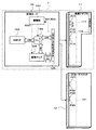
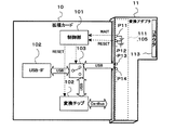
本発明を実施するための形態について図面を参照して詳細に説明する。図1は、本実施形態の機器接合補助システム1の構成を示す全体図である。機器接合補助システム1は、ある規格に準拠したコネクタをもつ拡張カードの、異なる規格に準拠した拡張スロットをもつ機器への接合を、変換用のアダプタを用いて補助するシステムである。同図を参照すると、機器接合補助システム1は、拡張カード10および変化アダプタ11を有する。
Embodiments for carrying out the present invention will be described in detail with reference to the drawings. FIG. 1 is an overall view showing a configuration of a device joining auxiliary system 1 of the present embodiment. The equipment joining assistance system 1 is a system that assists the joining of an expansion card having a connector compliant with a certain standard to equipment having an expansion slot compliant with a different standard by using a conversion adapter. Referring to FIG. 1, the device joining auxiliary system 1 includes an
拡張カード10は、CFカード規格に準拠したコネクタ(装着用コネクタ)を有するカード型情報機器である。例えば、拡張カード10は、データ通信機能をパソコンに追加するために使用される。
The
変換アダプタ11は、CFカード規格(第1の規格)対応のコネクタをエクスプレスカード規格(第2の規格)対応のコネクタに変換するアダプタである。
The
拡張カード10はCFカードタイプであるから、パソコン等にCFカード対応のCFカードスロット12がある場合、拡張カード10は、変換アダプタ11を用いることなくCFカードスロット12に装着される。
Since the
パソコン等にエクスプレスカード対応の拡張スロットしか設けられていない場合、拡張カード10は、変換アダプタ11を介してその拡張スロットに装着される。
When a personal computer or the like is provided only with an expansion slot compatible with an express card, the
拡張カード10は、制御部101、USB-IF102、アナログスイッチ103、変換チップ104、およびCFカード対応コネクタ104(カード側コネクタ)を有する。
The
制御部101は、変換アダプタ11から、所定の検出用信号を受信したとき、拡張カード10に変換アダプタ11が装着されたことを検出する。そして、変換アダプタ11の装着を検出したのであれば、制御部101は、検出した旨を通信部103に通知する。例えば、制御部101は、RESET信号およびWAIT信号を検出用信号として使用する。
When the
また、変換アダプタ11の装着を検出したとき、制御部101は、変換チップ104をリセット状態にするためのRESET信号を、変換チップ104へ送信する。これは、変換アダプタ11が装着されたときは、変換チップ104を動作する必要がないためである。
When detecting that the
図2は、変換アダプタ11における、CFカード対応コネクタのピンを介して送受信される信号の状態を示すテーブルである。同図を参照すると、このテーブルには、「ピン番号」、「信号名称」および「装着時の状態」が規定されている。
FIG. 2 is a table showing the state of signals transmitted / received via the pins of the CF card compatible connector in the
「ピン番号」は、コネクタの各ピン(端子)に割り当てられた番号である。「信号名称」は、ピンを介して送受信される信号の名称である。「装着時の状態」は、拡張カード10を変換アダプタ11に装着したときの信号の状態であり、低電流状態(L)または高電流状態(H)のいずれかの状態となる。
The “pin number” is a number assigned to each pin (terminal) of the connector. “Signal name” is a name of a signal transmitted / received via a pin. The “state at the time of attachment” is a state of a signal when the
例えば、ピン番号「P11」のピンを介して、「WAIT」信号が入出力され、ピン番号「P12」のピンを介して、「RESET」信号が入出力される。ピン番号「P13」のピンを介して、「D11」信号が入出力され、ピン番号「P14」のピンを介して、「D12」信号が入出力される。 For example, the “WAIT” signal is input / output via the pin number “P11”, and the “RESET” signal is input / output via the pin number “P12”. The “D11” signal is input / output via the pin number “P13”, and the “D12” signal is input / output via the pin number “P14”.
「WAIT」信号および「RESET」信号は、ともに負論理の信号であり、拡張スロットに装着時は、高電流状態(H)となり、パソコン等の制御によって低電流状態(L)となる。但し、パソコン等により、「RESET」信号および「WAIT」信号の双方が同時に低電流状態(L)に制御されることはない。 Both the “WAIT” signal and the “RESET” signal are negative logic signals, and when mounted in the expansion slot, the signal is in a high current state (H) and is controlled by a personal computer or the like to be in a low current state (L). However, both the “RESET” signal and the “WAIT” signal are not simultaneously controlled to the low current state (L) by a personal computer or the like.
しかし、これらの信号を検出用の信号として使用する場合、変換アダプタ12のCFカード対応コネクタにおいて、ピン番号「P11」および「P12」のピンを、いずれも接地しておく。この場合、「RESET」信号および「WAIT」信号は、装着時にともに低電流状態「L」となるので、拡張カード10は、変換アダプタ11の装着を検出することができる。
However, when these signals are used as detection signals, the pins of the pin numbers “P11” and “P12” are both grounded in the CF card connector of the
「D11」信号および「D12」信号は、カードバス規格(第1の規格)に準拠した信号である。 The “D11” signal and the “D12” signal are signals compliant with the card bus standard (first standard).
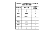
図3は、CFカードスロット11における、CFカード対応コネクタのピンを介して送受信される信号の状態を示すテーブルである。同図を参照すると、このテーブルには、「ピン番号」、「信号名称」および「装着時の状態」が規定されている。
FIG. 3 is a table showing the state of signals transmitted and received through the pins of the CF card compatible connector in the
例えば、ピン番号「P21」のピンを介して、「WAIT」信号が、入出力され、ピン番号「P22」のピンを介して、「RESET」信号が、入出力される。ピン番号「P23」のピンを介して、「USB+」信号が、入出力され、ピン番号「P24」のピンを介して、「USB−」信号が、入出力される。 For example, the “WAIT” signal is input / output via the pin number “P21”, and the “RESET” signal is input / output via the pin number “P22”. The “USB +” signal is input / output via the pin with the pin number “P23”, and the “USB−” signal is input / output via the pin with the pin number “P24”.
「USB+」信号および「USB−」信号は、USB規格(第2の規格)に準拠するデータを送受信するための信号である。 The “USB +” signal and the “USB−” signal are signals for transmitting and receiving data conforming to the USB standard (second standard).
拡張カード10が、CFカードスロット12に装着されたとき、「WAIT」信号および「RESET」信号は、ともに「H」の状態となる。
When the
図1に戻り、制御部101は、「WAIT」信号および「RESET」信号が双方とも低電流状態「L」であれば、変換アダプタ11が装着されたことを検出する。
Returning to FIG. 1, the
なお、変換アダプタ12の装着を検出できるのであれば、「RESET」信号および「WAIT」信号以外の信号を検出用信号として使用してもよいのは勿論である。
Of course, signals other than the “RESET” signal and the “WAIT” signal may be used as detection signals as long as the attachment of the
USB−IF102は、USB規格に準拠したデータを処理する回路又は部品であり、アナログスイッチ103の接点に接続されている。
The USB-IF 102 is a circuit or component that processes data conforming to the USB standard, and is connected to a contact point of the
アナログスイッチ103は、制御部101による検出の有無に応じて、回線の切り替えを行う回路または部品である。アナログスイッチ103の各接点は、それぞれ、USB−IF102、変換チップ104、CFカード対応コネクタ105に接続されている。アナログスイッチ103は、初期状態において、USB−IF102と変換チップ104とを接続している。そして、制御部101が変換アダプタ11の装着を検出すれば、アナログスイッチ103は、USB−IF102の接続先をCFカード対応コネクタ105へ切り替える。
The
そして、接続先が切り替えられた後、拡張カード10がスロットに装着され、制御部101により変換アダプタ11の装着が検出されなければ、アナログスイッチ103は、USB−IF102の接続先を変換チップ104に戻す。
After the connection destination is switched, if the
変換チップ104は、USB規格に準拠した信号とカードバス規格に準拠した信号とを相互に変換する回路または部品である。変換チップ104において、USB規格に準拠した信号を送受信する接点は、アナログスイッチ103の接点に接続され、カードバス規格に対応した信号を入出力する接点は、CFカード対応コネクタ105に接続されている。変換チップ104は、制御部103またはパソコン等からRESET信号を受信したとき、リセット状態となる。
The
CFカード対応コネクタ105は、CFカード規格に準拠するコネクタである。
The CF card
通信部103は、CFカード対応コネクタ105を介して、USB規格に準拠した信号、またはカードバス規格に準拠した信号を、他の装置(パソコン等)との間で入出力する。
The
なお、通信部103の構成は、変化アダプタ11の装着の検出の有無に応じて、USB規格のデータまたはカードバス規格のデータを送受信する構成であれば、図1に示した構成に限られない。
The configuration of the
変換アダプタ11は、CFカード対応コネクタ111およびエクスプレスカード対応コネクタ113を有する。CFカード対応コネクタ111は、カードバス規格に準拠するコネクタであり、エクスプレスカード対応コネクタ113は、エクスプレスカード規格に準拠するコネクタであり、これらのコネクタは、電気的に接続されている。また、CFカード対応コネクタ111において、WAIT信号およびRESET信号に対応するピン(P11、P12)は、接地されている。拡張カード10が変換アダプタ11の装着を検出できるようにするためである。
The
CFカードスロット12は、CFカードを挿入するためにパソコン等に設けられた拡張スロットである。CFカードスロット12は、CFカード対応コネクタ121を有する。
The
CFカード対応コネクタ121は、カードバス規格に準拠するコネクタである。
The CF card
次に、図4を参照して、拡張カード10の動作について説明する。この動作は、拡張カード10が変換アダプタ11またはCFカードスロット12に装着されたときに開始する。
Next, the operation of the
制御部101は、「WAIT」信号および「RESET」信号がともに低電流状態(L)であるか否かを判断する(ステップS1)。
The
「WAIT」信号および「RESET」信号がともに「L」であれば(ステップS1:YES)、アナログスイッチ103は、USB−IF102の接続先を、カードバス対応コネクタ105に切り替える(ステップS3)。制御部101は、変換チップ104にRESET信号を送信する(ステップS5)。
If both the “WAIT” signal and the “RESET” signal are “L” (step S1: YES), the
「WAIT」信号および「RESET」信号がともに「L」でなければ(ステップS1:NO)、アナログスイッチ103は、USB−IF102と変換チップ104とを接続する(ステップS7)。ステップS7の後、拡張カード10は動作を終了する。
If neither the “WAIT” signal nor the “RESET” signal is “L” (step S1: NO), the
次に、図5および図6を参照して、拡張カード10の動作について説明する。図5は、拡張カード10をCFカードスロット12に装着したときの動作を説明するための図である。同図を参照すると、「RESET」信号および「WAIT」信号がともに「H」なので(ステップS1:NO)、アナログスイッチ103は、USB−IF102と変換チップ104とを接続する(ステップS7)。拡張カード10は、変換チップ104により変換された、カードバス規格に準拠する信号を、パソコン等との間で入出力する。
Next, the operation of the
図6は、拡張カード10を変換アダプタ11に装着したときの動作を説明するための図である。同図を参照すると、「WAIT」信号および「RESET」信号がともに接地されて「L」なので(ステップS1:YES)、アナログスイッチ103は、USB−IF102の接続先を、カードバス対応コネクタ105に切り替え(ステップS3)、制御部101は、変換チップ104にRESET信号を送信する(ステップS5)。拡張カード10は、USB規格に準拠する信号を、パソコン等との間で入出力する。
FIG. 6 is a diagram for explaining the operation when the
なお、本実施形態では、CFカードタイプでなく、PCMCIAカードタイプなど、他の規格に準拠する拡張カードに検出部101および通信部103と同様の部品または回路を実装してもよいのは勿論である。
In the present embodiment, the same components or circuits as those of the
また、変換アダプタ12は、物理層レベルで信号が異なる規格のコネクタを相互に変換するアダプタであれば、CFカード規格のコネクタをUSB規格のコネクタに変換するものなど、CFカード規格およびエクスプレスカード規格以外の規格に対応するコネクタを相互変換するアダプタであってもよい。
If the
さらに、変換アダプタ11は、コネクタを変換するものであれば、アダプタに限らず、変換治具や組み込み機器であってもよい。
Furthermore, the
以上説明したように、本実施形態によれば、拡張カード10は、変換アダプタ12が装着されていなければカードバス規格に準拠する信号を、変換アダプタ12が装着されていればUSB規格に準拠する信号を、CFカード対応コネクタ105を介して入出力するので、変換アダプタ11は、信号を変換するための部品または回路を実装する必要がなく、低コストで小型の変換アダプタを実現することができる。
As described above, according to this embodiment, the
変換チップ104は、変換アダプタ12が装着されたことが検出されている間、動作を停止するので、変換チップ104の消費電力を節約することができる。
The
制御部101は、ERSET信号およびWAIT信号がともに低電流状態となったとき、すなわち、変換アダプタ11が装着されたとき以外は起こらない組み合わせになったとき、変換アダプタ12を検出するので、誤って検出されることなく、確実に変換アダプタ12の装着を検出することができる。
Since the
なお、図4に示した処理の一部又は全ては、コンピュータプログラムの実行により実現してもよい。 Note that part or all of the processing illustrated in FIG. 4 may be realized by executing a computer program.
1 機器接合補助システム
10 拡張カード
11 変換アダプタ
12 CFカードスロット
101 制御部
111、121、105 CFカード対応コネクタ
113 エクスプレスカード対応コネクタ
102 USB−IF
103 アナログスイッチ
104 変換チップ
P11〜P14、P21〜P24 ピン番号
S1〜S7 ステップ
DESCRIPTION OF SYMBOLS 1 Device joining
103
Claims (13)
前記装着用コネクタに、前記第1規格に準拠したコネクタを第2の規格に準拠したコネクタに変換するアダプタが装着されたことを検出する検出手段と、
前記第2の規格に準拠した内部信号である第2の信号を前記第1の規格に準拠した第1の信号に変換する変換手段と、
前記検出手段により前記装着用コネクタに前記アダプタが装着されたことが検出されない場合、前記変換手段により変換された前記第1の信号を、前記装着用コネクタを介して入出力し、前記検出手段により前記装着用コネクタに前記アダプタが装着されたことが検出された場合、前記第2の信号を、前記装着用コネクタを介して入出力する、切替手段と、
を有するカード型情報機器。 A mounting connector conforming to the first standard;
Detecting means for detecting that an adapter for converting a connector conforming to the first standard to a connector conforming to the second standard is mounted on the mounting connector;
Conversion means for converting a second signal, which is an internal signal compliant with the second standard, into a first signal compliant with the first standard;
If the detection means does not detect that the adapter is attached to the attachment connector, the first signal converted by the conversion means is input / output via the attachment connector, and the detection means A switching means for inputting / outputting the second signal via the mounting connector when it is detected that the adapter is mounted on the mounting connector;
Card-type information equipment having.
第1の規格に準拠した装着用コネクタを有し、該装着用コネクタに、前記アダプタが装着されるのを監視し、該装着用コネクタに該アダプタが装着されたことが検出されない場合、前記第2の規格に準拠した内部信号である第2の信号を前記第1の規格に準拠するように変換した第1の信号を、該装着用コネクタを介して入出力し、該装着用コネクタに該アダプタが装着されたことが検出された場合、前記第2の信号を、前記装着用コネクタを介して入出力する、カード型情報機器と、
を有する機器接合補助システム。 An adapter comprising a connector conforming to the first standard and a connector conforming to the second standard, and interconnecting corresponding terminals of the connector conforming to the first standard and the connector conforming to the second standard When,
A mounting connector that conforms to the first standard, and monitoring that the adapter is mounted on the mounting connector; if it is not detected that the adapter is mounted on the mounting connector; The first signal obtained by converting the second signal, which is an internal signal conforming to the standard 2 to be compliant with the first standard, is input / output via the mounting connector, and the first signal is input to the mounting connector. A card type information device that inputs and outputs the second signal via the mounting connector when it is detected that an adapter is mounted;
Equipment joining assist system.
第2の規格に準拠したコネクタと、
前記第1の規格に準拠したコネクタと前記第2の規格に準拠したコネクタの対応する端子同士を相互に接続する接続手段と、
前記第1の規格に準拠したコネクタの複数のピンのうち、所定の組み合わせのピンを接地する接地手段と、
を有するアダプタ。 A connector conforming to the first standard;
A connector conforming to the second standard;
Connection means for connecting corresponding terminals of the connector compliant with the first standard and the connector compliant with the second standard;
A grounding means for grounding a predetermined combination of pins among the plurality of pins of the connector conforming to the first standard;
Having an adapter.
前記装着用コネクタに、前記第1規格に準拠したコネクタを第2の規格に準拠したコネクタに変換するアダプタが装着されるのを監視し、
前記装着用コネクタに前記アダプタが装着されたことが検出されない場合、前記第2の規格に準拠した内部信号である第2の信号を前記第1の規格に準拠するように変換した第1の信号を、前記装着用コネクタを介して入出力し、
前記装着用コネクタに前記アダプタが装着されたことが検出された場合、前記第2の信号を、前記装着用コネクタを介して入出力する、カード型情報機器の制御方法。 A control method for a card-type information device having a mounting connector compliant with the first standard,
Monitoring that the adapter for converting the connector conforming to the first standard to the connector conforming to the second standard is mounted on the connector for mounting;
When it is not detected that the adapter is attached to the attachment connector, a first signal obtained by converting a second signal, which is an internal signal conforming to the second standard, to conform to the first standard Input / output via the mounting connector,
A control method for a card-type information device, wherein when it is detected that the adapter is attached to the attachment connector, the second signal is input / output via the attachment connector.
Priority Applications (1)
| Application Number | Priority Date | Filing Date | Title |
|---|---|---|---|
| JP2008167321A JP5218968B2 (en) | 2008-06-26 | 2008-06-26 | CARD TYPE INFORMATION DEVICE, DEVICE CONNECTION ASSISTANCE SYSTEM, AND CARD TYPE INFORMATION DEVICE CONTROL METHOD |
Applications Claiming Priority (1)
| Application Number | Priority Date | Filing Date | Title |
|---|---|---|---|
| JP2008167321A JP5218968B2 (en) | 2008-06-26 | 2008-06-26 | CARD TYPE INFORMATION DEVICE, DEVICE CONNECTION ASSISTANCE SYSTEM, AND CARD TYPE INFORMATION DEVICE CONTROL METHOD |
Publications (2)
| Publication Number | Publication Date |
|---|---|
| JP2010009286A true JP2010009286A (en) | 2010-01-14 |
| JP5218968B2 JP5218968B2 (en) | 2013-06-26 |
Family
ID=41589711
Family Applications (1)
| Application Number | Title | Priority Date | Filing Date |
|---|---|---|---|
| JP2008167321A Active JP5218968B2 (en) | 2008-06-26 | 2008-06-26 | CARD TYPE INFORMATION DEVICE, DEVICE CONNECTION ASSISTANCE SYSTEM, AND CARD TYPE INFORMATION DEVICE CONTROL METHOD |
Country Status (1)
| Country | Link |
|---|---|
| JP (1) | JP5218968B2 (en) |
Citations (10)
| Publication number | Priority date | Publication date | Assignee | Title |
|---|---|---|---|---|
| JPH06131083A (en) * | 1992-10-15 | 1994-05-13 | Mita Ind Co Ltd | Interface switching device |
| JPH11119878A (en) * | 1997-07-08 | 1999-04-30 | Shuttle Technol Ltd | Computer interface device |
| JP2004046608A (en) * | 2002-07-12 | 2004-02-12 | Fuji Photo Film Co Ltd | Electronic apparatus connecting method for memory card and memory card adapter |
| JP2004110255A (en) * | 2002-09-17 | 2004-04-08 | Ricoh Co Ltd | Pc card controller, computer system therewith, and method for identifying pc card |
| JP3103833U (en) * | 2003-11-14 | 2004-08-26 | 萬國電脳股▲ふん▼有限公司 | Express card interface adapter device suitable for small storage media |
| JP2005007255A (en) * | 2003-06-18 | 2005-01-13 | Kazuo Ishizuka | Processing method and processing apparatus for infectious waste |
| JP2005346123A (en) * | 2004-05-31 | 2005-12-15 | Toshiba Corp | Storage device equipped with parallel interface connector and conversion connector applied to same device |
| JP3120359U (en) * | 2005-04-27 | 2006-03-30 | 翼慶企業股▲ふん▼有限公司 | PC card structure |
| JP2008171377A (en) * | 2007-01-08 | 2008-07-24 | Alcor Micro Corp | Expresscard device |
| JP2009070255A (en) * | 2007-09-14 | 2009-04-02 | Sony Corp | Card type peripheral device |
-
2008
- 2008-06-26 JP JP2008167321A patent/JP5218968B2/en active Active
Patent Citations (10)
| Publication number | Priority date | Publication date | Assignee | Title |
|---|---|---|---|---|
| JPH06131083A (en) * | 1992-10-15 | 1994-05-13 | Mita Ind Co Ltd | Interface switching device |
| JPH11119878A (en) * | 1997-07-08 | 1999-04-30 | Shuttle Technol Ltd | Computer interface device |
| JP2004046608A (en) * | 2002-07-12 | 2004-02-12 | Fuji Photo Film Co Ltd | Electronic apparatus connecting method for memory card and memory card adapter |
| JP2004110255A (en) * | 2002-09-17 | 2004-04-08 | Ricoh Co Ltd | Pc card controller, computer system therewith, and method for identifying pc card |
| JP2005007255A (en) * | 2003-06-18 | 2005-01-13 | Kazuo Ishizuka | Processing method and processing apparatus for infectious waste |
| JP3103833U (en) * | 2003-11-14 | 2004-08-26 | 萬國電脳股▲ふん▼有限公司 | Express card interface adapter device suitable for small storage media |
| JP2005346123A (en) * | 2004-05-31 | 2005-12-15 | Toshiba Corp | Storage device equipped with parallel interface connector and conversion connector applied to same device |
| JP3120359U (en) * | 2005-04-27 | 2006-03-30 | 翼慶企業股▲ふん▼有限公司 | PC card structure |
| JP2008171377A (en) * | 2007-01-08 | 2008-07-24 | Alcor Micro Corp | Expresscard device |
| JP2009070255A (en) * | 2007-09-14 | 2009-04-02 | Sony Corp | Card type peripheral device |
Also Published As
| Publication number | Publication date |
|---|---|
| JP5218968B2 (en) | 2013-06-26 |
Similar Documents
| Publication | Publication Date | Title |
|---|---|---|
| JP2019096282A (en) | Hub | |
| JP5283719B2 (en) | Electronic equipment and electronic equipment system | |
| US8585442B2 (en) | Expansion card adapter | |
| CN109558371B (en) | Method for communicating with a microcontroller, and computing system | |
| CN101989246A (en) | Electronic device capable of automatically switching master and slave equipment modes of universal serial bus (USB) | |
| CN111404564A (en) | Electronic equipment | |
| EP2146286A2 (en) | Converter and control system | |
| CN106445858B (en) | Information processing method, information processing module and electronic equipment | |
| US20120005385A1 (en) | Communication circuit of inter-integrated circuit device | |
| US9201650B2 (en) | Super I/O module and control method thereof | |
| US10203961B2 (en) | BIOS control method for PCI-E lane | |
| TWI291101B (en) | Bus adapter, method thereof, and computer system thereof | |
| JP5217939B2 (en) | Expansion card, fault diagnosis processing method, information processing apparatus, and fault diagnosis processing program | |
| JP5218968B2 (en) | CARD TYPE INFORMATION DEVICE, DEVICE CONNECTION ASSISTANCE SYSTEM, AND CARD TYPE INFORMATION DEVICE CONTROL METHOD | |
| JP5797949B2 (en) | Communication device | |
| US20070299929A1 (en) | Client device interface for portable communication devices | |
| TWI582604B (en) | External device, electronic device and electronic system | |
| JP6267346B2 (en) | SIM card signal conversion method and signal conversion apparatus | |
| CN109582620B (en) | UART interface conversion device and method | |
| EP3803612B1 (en) | A communication apparatus | |
| US20110289246A1 (en) | Super i/o module, computer system and control method thereof | |
| CN106909198B (en) | External device, electronic device and electronic system | |
| JP7371260B2 (en) | Electronic equipment and connection inspection method | |
| JP2016218943A (en) | Communication device, communication control method, and communication control program | |
| CN218849054U (en) | Display device and debugging system thereof |
Legal Events
| Date | Code | Title | Description |
|---|---|---|---|
| A621 | Written request for application examination |
Free format text: JAPANESE INTERMEDIATE CODE: A621 Effective date: 20100921 |
|
| A131 | Notification of reasons for refusal |
Free format text: JAPANESE INTERMEDIATE CODE: A131 Effective date: 20120228 |
|
| A521 | Written amendment |
Free format text: JAPANESE INTERMEDIATE CODE: A523 Effective date: 20120501 |
|
| A131 | Notification of reasons for refusal |
Free format text: JAPANESE INTERMEDIATE CODE: A131 Effective date: 20121106 |
|
| A521 | Written amendment |
Free format text: JAPANESE INTERMEDIATE CODE: A523 Effective date: 20130104 |
|
| TRDD | Decision of grant or rejection written | ||
| A01 | Written decision to grant a patent or to grant a registration (utility model) |
Free format text: JAPANESE INTERMEDIATE CODE: A01 Effective date: 20130205 |
|
| A61 | First payment of annual fees (during grant procedure) |
Free format text: JAPANESE INTERMEDIATE CODE: A61 Effective date: 20130225 |
|
| FPAY | Renewal fee payment (event date is renewal date of database) |
Free format text: PAYMENT UNTIL: 20160315 Year of fee payment: 3 |
|
| R150 | Certificate of patent or registration of utility model |
Ref document number: 5218968 Country of ref document: JP Free format text: JAPANESE INTERMEDIATE CODE: R150 Free format text: JAPANESE INTERMEDIATE CODE: R150 |
|
| S533 | Written request for registration of change of name |
Free format text: JAPANESE INTERMEDIATE CODE: R313533 |
|
| R350 | Written notification of registration of transfer |
Free format text: JAPANESE INTERMEDIATE CODE: R350 |