JP2010003838A - Reactor device - Google Patents
Reactor device Download PDFInfo
- Publication number
- JP2010003838A JP2010003838A JP2008160921A JP2008160921A JP2010003838A JP 2010003838 A JP2010003838 A JP 2010003838A JP 2008160921 A JP2008160921 A JP 2008160921A JP 2008160921 A JP2008160921 A JP 2008160921A JP 2010003838 A JP2010003838 A JP 2010003838A
- Authority
- JP
- Japan
- Prior art keywords
- reactor
- case
- resin
- coil
- protrusion
- Prior art date
- Legal status (The legal status is an assumption and is not a legal conclusion. Google has not performed a legal analysis and makes no representation as to the accuracy of the status listed.)
- Granted
Links
Images


Abstract
Description
本発明は、容器内にコイルを固定する樹脂を注入してなるリアクトル装置に関するものである。 The present invention relates to a reactor device in which a resin for fixing a coil is injected into a container.
ハイブリッド自動車に用いられるバッテリの昇圧を行うDC−DCコンバータにおいて、リアクトルが用いられる。リアクトルはコイルとコアとを備えるものであり、絶縁性や耐熱性の観点から、コイルを磁性鉄粉混入樹脂で封止するコイル封止型リアクトルが知られている(例えば、特許文献1参照)。リアクトルは、作動時に発熱するため、ヒートシンクなどの放熱部材を密着させて、熱を外部に逃がすことが望ましい。そして、リアクトルを密着させる放熱部材の形状を上面が開口した筐体にすると、底面だけでなく側面からも放熱でき、効率的にリアクトルを放熱することができる。
リアクトルの側面と放熱部材との間には、隙間を埋めるために樹脂を充填することが行われるが、樹脂の熱伝導率は高くはない。更には、樹脂が硬化するまでに時間がかかり、コスト高になるという問題もある。 A resin is filled between the side surface of the reactor and the heat radiating member to fill the gap, but the thermal conductivity of the resin is not high. Furthermore, there is a problem that it takes time until the resin is cured, resulting in an increase in cost.
本発明の目的は上記課題に鑑みたものであり、放熱性に優れ、かつ、簡易にリアクトルの組付けができるリアクトル装置を提供することにある。 An object of the present invention is to provide a reactor device that is excellent in heat dissipation and can be easily assembled.
請求項1に係る発明では、通電により磁束を発生させるコイルと、コイルが発生した磁束の磁路となるコアと、コイルを固定する樹脂とを、備えるリアクトル装置において、コイルとコアと樹脂とを内部に収容する成形ケースと、成形ケースを内側に収容するリアクトルケースとを備え、成形ケースは、外表面にリアクトルケースの内面と接触する突起を有することを特徴とする。
In the invention which concerns on
本発明によれば、成形ケースの突起がリアクトルケースの内面と接触しているため、突起を介して放熱を行うことができる。 According to the present invention, since the projection of the molding case is in contact with the inner surface of the reactor case, heat can be radiated through the projection.
成形ケースをリアクトルケースに収容する際に突起を潰すことにより突起が放熱材の役割を果たすため、放熱材として一般に用いられる樹脂をリアクトルとリアクトルケースとの間に充填するよりも簡易にリアクトルの製造を行うことができる。具体的には、樹脂を充填する工程や樹脂を硬化させる工程が不要となる。 Reactor manufacturing is easier than filling resin that is commonly used as heat dissipation material between the reactor and the reactor because the protrusion plays the role of a heat dissipation material by crushing the protrusion when housing the molded case in the reactor case. It can be performed. Specifically, the step of filling the resin and the step of curing the resin are not necessary.
また、放熱性を高めたいところに重点的に突起させることによって、充填時に流動する樹脂を用いた場合より正確な放熱設計を図ることができる。 In addition, by projecting mainly at a place where heat dissipation is desired, a more accurate heat radiation design can be achieved than when a resin that flows during filling is used.
成形ケース内において、樹脂でコイルを封止しているため、絶縁性や防水性が向上し、樹脂を介して成形ケースの広域に熱を拡散することができる。 Since the coil is sealed with resin in the molding case, insulation and waterproofness are improved, and heat can be diffused over a wide area of the molding case via the resin.
請求項2に係る発明では、成形ケースは、外表面の底面部に突起を有することを特徴とする。 In the invention which concerns on Claim 2, a shaping | molding case has a processus | protrusion in the bottom face part of an outer surface.
本発明によれば、外表面の底面部は成形ケース収容時の圧力が大きいため、容易に突起を潰すことができ、組付け性能が向上する。 According to the present invention, since the bottom surface portion of the outer surface has a large pressure when the molding case is accommodated, the protrusion can be easily crushed, and the assembling performance is improved.
請求項3に係る発明では、突起は、コイルに近づくにつれて突起の単位面積あたりの数が多くなることを特徴とする。 The invention according to claim 3 is characterized in that the number of protrusions per unit area of the protrusions increases as approaching the coil.
本発明によれば、発熱源であるコイルに近づくにつれて突起を多く設けるため、発熱箇所からの放熱性向上を図ることができる。 According to the present invention, since many protrusions are provided as the coil that is the heat generation source is approached, it is possible to improve heat dissipation from the heat generation point.
請求項4に係る発明では、突起は、コイルに近づくにつれて突起の形状が大きくなることを特徴とする。 The invention according to claim 4 is characterized in that the shape of the protrusion increases as it approaches the coil.
本発明によれば、発熱減であるコイルに近づくにつれて突起の形状を大きくするため、発熱箇所からの放熱性向上を図ることができる。 According to the present invention, since the shape of the protrusion is increased as it approaches the coil where heat generation is reduced, it is possible to improve heat dissipation from the heat generation point.
請求項5に係る発明では、成形ケースは、成形ケースに充填された樹脂の上面よりも下方において、外表面の側面部に突起を有することを特徴とする。 The invention according to claim 5 is characterized in that the molding case has a protrusion on the side surface portion of the outer surface below the upper surface of the resin filled in the molding case.
本発明によれば、熱伝達媒体となっている樹脂の上面より下方に突起を設けているため、発熱箇所からの放熱性向上を図ることができる。 According to the present invention, since the protrusion is provided below the upper surface of the resin serving as the heat transfer medium, it is possible to improve the heat dissipation from the heat generation point.
請求項6に係る発明では、側面部に設けた突起は、樹脂の上面に向かうにつれて、突起の単位面積あたりの数が多くなることを特徴とする。 The invention according to claim 6 is characterized in that the number of protrusions provided on the side surface portion per unit area of the protrusion increases toward the upper surface of the resin.
本発明によれば、熱が伝わりやすい樹脂の上面に向かうにつれて、突起を多く設けるため、放熱性向上を図ることができる。 According to the present invention, since more protrusions are provided toward the upper surface of the resin that easily transfers heat, it is possible to improve heat dissipation.
請求項7に係る発明では、側面部に設けた突起は、樹脂の上面に向かうにつれて、突起の形状の大きくなることを特徴とする。 The invention according to claim 7 is characterized in that the protrusion provided on the side surface portion increases in shape toward the upper surface of the resin.
本発明によれば、熱が伝わりやすい樹脂の上面に向かうにつれて、突起の形状を大きくするため、放熱性向上を図ることができる。 According to the present invention, since the shape of the protrusion is increased toward the upper surface of the resin where heat is easily transmitted, the heat dissipation can be improved.
請求項8に係る発明では、成形ケースは、内周面に樹脂と係合する凹部を有することを特徴とする。 The invention according to claim 8 is characterized in that the molded case has a recess engaging with the resin on the inner peripheral surface.
本発明によれば、成形ケースの内周面に樹脂と係合する凹部を設けるため、リアクトルの成形ケースからの離脱を防ぐことができる。 According to the present invention, since the concave portion that engages with the resin is provided on the inner peripheral surface of the molding case, it is possible to prevent the reactor from being detached from the molding case.
請求項9に係る発明では、成形ケースはコイルの中心部分にねじ穴を有し、リアクトルケースは、底面部にねじ穴と対向する締結穴を有し、締結穴を貫通してねじ穴に締結するボルトを有することを特徴とする。 In the invention according to claim 9, the molded case has a screw hole in the central portion of the coil, and the reactor case has a fastening hole facing the screw hole on the bottom surface, and is fastened to the screw hole through the fastening hole. It is characterized by having the bolt which carries out.
本発明によれば、成形ケースがコイルの中心軸にねじ穴を形成するため、ねじ穴形成によるコイルの磁束形成の阻害を軽減しつつも、成形ケースがリアクトルケースから離脱する事態を防ぐことができる。 According to the present invention, since the molding case forms a screw hole in the central axis of the coil, it is possible to prevent the molding case from being detached from the reactor case while reducing the inhibition of the magnetic flux formation of the coil due to the screw hole formation. it can.
請求項10に係る発明では、コアは磁性鉄粉からなり、コアと樹脂とが、磁性鉄粉と樹脂とを混入した磁性鉄粉混入樹脂を形成することを特徴とする。 The invention according to claim 10 is characterized in that the core is made of magnetic iron powder, and the core and the resin form a magnetic iron powder mixed resin in which the magnetic iron powder and the resin are mixed.
磁性鉄粉混入樹脂を用いることで、磁束が外部に漏洩することを防ぐことができる。 By using the magnetic iron powder mixed resin, it is possible to prevent the magnetic flux from leaking to the outside.
請求項11に係る発明では、リアクトルケース、突起および成形ケースは、アルミニウムからなることを特徴とする。
The invention according to
本発明によれば、展性、延性が富むアルミニウムを突起に用いるため、成形ケースからをリアクトルケースに収容した際に突起が容易に変形し容易にリアクトルの組付けを行うことができる。 According to the present invention, since aluminum having excellent malleability and ductility is used for the projection, the projection is easily deformed when the molded case is accommodated in the reactor case, and the reactor can be easily assembled.
また、突起、リアクトルケース、成形ケースともにアルミニウムを採用することで、放熱性も向上できる。 Moreover, heat dissipation can also be improved by adopting aluminum for the protrusion, the reactor case, and the molded case.
(実施例1)
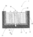
図1に本発明の実施例1に係る成形ケースおよびリアクトルケースの縦断面図、図2に本発明の実施例1に係るリアクトル装置の縦断面図を示す。
Example 1
FIG. 1 is a longitudinal sectional view of a molding case and a reactor case according to
リアクトル装置1は、通電により磁束を発生させるコイル12と、コイル12が発生した磁束の磁路となるコア13と、コイル12を成形ケース11に封止して固定する樹脂14とを備え、リアクトルケース30の内側にコイル12とコア13と樹脂14とを内部に収容する成形ケース11を収容することで形成される。
The
実施例1においては、コア13は磁性鉄粉からなり、コア13と樹脂14とが、コア13と樹脂14とを混入したダストコア15(磁性鉄粉混合樹脂)を形成する。ダストコア15はコイル12の内外に充填される。ダストコア15に用いられる磁性鉄粉としては、軟磁性を示すソフトフェライト粉末、樹脂14としては、耐熱性や絶縁性、接着性に優れるエボキシ樹脂14の他、ポリフェニレンサルファイド(PPS)、ポリブチレンテレフタレート(PBT)などが用いられる。
In Example 1, the
また、図3に示すように、積層鋼板をコア13とし、積層鋼板とコイル12の周囲に樹脂14を充填してもよい。
Further, as shown in FIG. 3, a laminated steel plate may be used as the
成形ケース11は、コイル12とコア13と樹脂14を内部に収容するものであり、成形ケース11は、外表面16の底面部17や側面部18に突起19を有する。突起19は底面部17と側面部18のいずれか一方にのみ形成されていてもよい。成形ケース11に設けられた突起19は、成形ケース11をリアクトルケース30に圧入して収容すると、リアクトルケース側からの圧力により変形する。この結果、突起19が成形ケース11とリアクトルケース30との隙間に入り込む。成形ケース11の外表面16に突起19を設けることによって、通常の平らな面からなる成形ケース11を採用した場合と比べて、確実に狙った分だけリアクトルケース30と成形ケース11との放熱経路を形成することができる。また、従来では、成形ケース11とリアクトルケース30との間に樹脂を用いていたが、樹脂は流動するため、樹脂が厚く滞留した箇所には放熱性が低下する問題があった。本発明では、突起19によって、ケース間の放熱経路を確保するので、発熱量が多い箇所を狙って放熱経路を確保できる。さらには、樹脂の充填工程や樹脂硬化工程が不要になるため、リアクトルケースへの組付けが簡単になる。
The molded
成形ケース11、突起19及びリアクトルケース30は、耐熱性や放熱性の優れたアルミニウム等の金属からなることが望ましい。特に、リアクトルケース30は、ヒートシンク等の放熱部材からなることが望ましい。
The molded
リアクトル装置1は、リアクトルケース30内に成形ケース11を圧入して収容することで形成される。リアクトルケース30に成形ケース11を収容するで、成形ケース11の突起19は、リアクトルケース30からの圧力により変形し、成形ケース11とリアクトルケース30との隙間に突起19が入り込むこととなる。この結果、成形ケース11の突起19はリアクトルケース30と成形ケース11との間に放熱経路が形成される。
The
変形した突起19は、リアクトルケース30の内面31の全面と接触するわけではないが、成形ケース11や突起19にアルミニウムなどの熱伝導率が高い部材を採用することで、コイル12からの熱を十分に放熱させることができる。熱伝導率の高い金属の例として、銅やアルミニウムがあり、それぞれの常温での熱伝導率は銅390W/(m・K)、アルミニウム236W/(m・K)である。一方、放熱材として一般に用いられるエポキシ樹脂14の熱伝導率は、0.21W/(m・K)である。したがって、リアクトルとリアクトルケース30との間の熱を伝導させる媒体として、金属を採用し、かつ、突起19をその接触面積を確保できる構造にすることで放熱性の向上が期待できる。
The
(変形例1)
図4に本発明の変形例1に係る成形ケースの縦断面図を示す。
(Modification 1)
FIG. 4 shows a longitudinal sectional view of a molded case according to
成形ケース11は、外表面16の底面部17において突起19を有している。突起19はコイル12に近づくにつれて単位面積あたりの数が多くなり、加えて、コイル12に近づくにつれて突起19の形状が大きくなる。発熱源であるコイル12に近い部分の放熱経路を確実に確保することができるからである。また、発熱源から遠くなるにつれて、突起19の数を減らしたり、形状を小さくしてもよい。この結果、リアクトルケース30に成形ケース11を収容した際の発熱源近くに設けられた突起19への加圧が増し、確実に放熱経路を形成することができる。
The molded
また、成形ケース11は、充填された樹脂14の上面よりも下方において、外表面16の側面部18に突起19を有してもよい。この場合、樹脂14の上面に向かうにつれて、側面部18の突起19の単位面積あたりの数が多くなる。加えて、樹脂14の上面に向かうにつれて、側面部18の突起19の形状が大きくなる。この構成により、熱が伝達しやすい樹脂14上面付近の熱を効率的に放熱することができる。
Further, the molded
成形ケース11は、図5に示す成形ケース11の内周部における拡大図(図4の点線部分に相当)に示すように、内周面に樹脂14と係合する凹部32を有してもよい。凹部32を設けることによって、樹脂14が凹部32内に入り込み、樹脂で封止されたコイル12が成形ケース11から離脱することを低減することができる。
As shown in the enlarged view (corresponding to the dotted line portion in FIG. 4) of the inner peripheral portion of the
(変形例2)
図6に本発明の変形例に係るリアクトル装置1を示す。図5では、簡単のため突起部は省略する。成形ケース11はコイル12の中心部分にねじ穴を有し、リアクトルケース30は、底面部17にねじ穴21と対向する締結穴33を有し、締結穴を貫通してねじ穴に締結するボルト41を有する。この結果、成形ケース11とリアクトルケース30との締結力を向上させることができる。
(Modification 2)
FIG. 6 shows a
1 リアクトル装置
11 成形ケース
12 コイル
13 コア
14 樹脂
15 ダストコア(磁性鉄粉混合樹脂)
16 外表面
17 底面部
18 側面部
19 突起
20 樹脂の上面
21 ねじ穴
30 リアクトルケース
31 内面
32 凹部
33 締結穴
41 ボルト
DESCRIPTION OF
16
Claims (11)
前記コイルと前記コアと前記樹脂とを内部に収容する成形ケースと、前記成形ケースを内側に収容するリアクトルケースとを備え、前記成形ケースは、外表面に前記リアクトルケースの内面と接触する突起を有することを特徴とするリアクトル装置。 In a reactor device comprising: a coil that generates a magnetic flux by energization; a core that is a magnetic path of the magnetic flux generated by the coil; and a resin that fixes the coil.
A molding case that houses the coil, the core, and the resin inside, and a reactor case that houses the molding case inside, and the molding case has a protrusion that contacts the inner surface of the reactor case on the outer surface. A reactor device characterized by comprising:
前記突起の単位面積あたりの数が多くなることを特徴とする請求項5に記載のリアクトル装置。 As the protrusions provided on the side surface portion are directed toward the upper surface of the resin,
The reactor device according to claim 5, wherein the number of the protrusions per unit area increases.
前記突起の形状の大きくなることを特徴とする請求項5又は請求項6に記載のリアクトル装置。 As the protrusions provided on the side surface portion are directed toward the upper surface of the resin,
The reactor device according to claim 5, wherein the shape of the protrusion becomes large.
Priority Applications (1)
| Application Number | Priority Date | Filing Date | Title |
|---|---|---|---|
| JP2008160921A JP4968193B2 (en) | 2008-06-19 | 2008-06-19 | Reactor device |
Applications Claiming Priority (1)
| Application Number | Priority Date | Filing Date | Title |
|---|---|---|---|
| JP2008160921A JP4968193B2 (en) | 2008-06-19 | 2008-06-19 | Reactor device |
Publications (2)
| Publication Number | Publication Date |
|---|---|
| JP2010003838A true JP2010003838A (en) | 2010-01-07 |
| JP4968193B2 JP4968193B2 (en) | 2012-07-04 |
Family
ID=41585321
Family Applications (1)
| Application Number | Title | Priority Date | Filing Date |
|---|---|---|---|
| JP2008160921A Expired - Fee Related JP4968193B2 (en) | 2008-06-19 | 2008-06-19 | Reactor device |
Country Status (1)
| Country | Link |
|---|---|
| JP (1) | JP4968193B2 (en) |
Cited By (9)
| Publication number | Priority date | Publication date | Assignee | Title |
|---|---|---|---|---|
| WO2011104975A1 (en) * | 2010-02-25 | 2011-09-01 | 住友電気工業株式会社 | Reactor and method for manufacturing reactor |
| JP2011210791A (en) * | 2010-03-29 | 2011-10-20 | Denso Corp | Reactor, and method of manufacturing the same |
| CN103430249A (en) * | 2011-03-24 | 2013-12-04 | 住友电气工业株式会社 | Composite material, reactor core, reactor, converter, and power conversion device |
| JP2015518271A (en) * | 2012-03-20 | 2015-06-25 | クアルコム,インコーポレイテッド | Wireless power transfer device and manufacturing method |
| JP2015228412A (en) * | 2014-05-30 | 2015-12-17 | Tdk株式会社 | Inductor element |
| US9349511B2 (en) | 2011-03-24 | 2016-05-24 | Sumitomo Electric Industries, Ltd. | Composite material, reactor-use core, reactor, converter, and power converter apparatus |
| US9653206B2 (en) | 2012-03-20 | 2017-05-16 | Qualcomm Incorporated | Wireless power charging pad and method of construction |
| US9972434B2 (en) | 2012-03-20 | 2018-05-15 | Qualcomm Incorporated | Magnetically permeable structures |
| WO2020066122A1 (en) * | 2018-09-28 | 2020-04-02 | 株式会社明電舎 | Reactor |
Citations (8)
| Publication number | Priority date | Publication date | Assignee | Title |
|---|---|---|---|---|
| JPS5710728U (en) * | 1980-06-23 | 1982-01-20 | ||
| JPS61195025U (en) * | 1985-05-27 | 1986-12-04 | ||
| JPH0224079U (en) * | 1988-08-03 | 1990-02-16 | ||
| JP2007019402A (en) * | 2005-07-11 | 2007-01-25 | Denso Corp | Coil-sealing resin-molded reactor, and manufacturing method thereof |
| JP2007129817A (en) * | 2005-11-02 | 2007-05-24 | Toyota Motor Corp | Drive unit for vehicle |
| JP2007180145A (en) * | 2005-12-27 | 2007-07-12 | Denso Corp | Magnetic component |
| JP2008042094A (en) * | 2006-08-09 | 2008-02-21 | Denso Corp | Reactor |
| JP2008112856A (en) * | 2006-10-30 | 2008-05-15 | Sumitomo Electric Ind Ltd | Reactor apparatus |
-
2008
- 2008-06-19 JP JP2008160921A patent/JP4968193B2/en not_active Expired - Fee Related
Patent Citations (8)
| Publication number | Priority date | Publication date | Assignee | Title |
|---|---|---|---|---|
| JPS5710728U (en) * | 1980-06-23 | 1982-01-20 | ||
| JPS61195025U (en) * | 1985-05-27 | 1986-12-04 | ||
| JPH0224079U (en) * | 1988-08-03 | 1990-02-16 | ||
| JP2007019402A (en) * | 2005-07-11 | 2007-01-25 | Denso Corp | Coil-sealing resin-molded reactor, and manufacturing method thereof |
| JP2007129817A (en) * | 2005-11-02 | 2007-05-24 | Toyota Motor Corp | Drive unit for vehicle |
| JP2007180145A (en) * | 2005-12-27 | 2007-07-12 | Denso Corp | Magnetic component |
| JP2008042094A (en) * | 2006-08-09 | 2008-02-21 | Denso Corp | Reactor |
| JP2008112856A (en) * | 2006-10-30 | 2008-05-15 | Sumitomo Electric Ind Ltd | Reactor apparatus |
Cited By (19)
| Publication number | Priority date | Publication date | Assignee | Title |
|---|---|---|---|---|
| WO2011104975A1 (en) * | 2010-02-25 | 2011-09-01 | 住友電気工業株式会社 | Reactor and method for manufacturing reactor |
| JP2011199257A (en) * | 2010-02-25 | 2011-10-06 | Sumitomo Electric Ind Ltd | Method for manufacturing reactor |
| CN102782783A (en) * | 2010-02-25 | 2012-11-14 | 住友电气工业株式会社 | Reactor and method for manufacturing reactor |
| EP2541563A4 (en) * | 2010-02-25 | 2017-07-05 | Sumitomo Electric Industries, Ltd. | Reactor and method for manufacturing reactor |
| US8830022B2 (en) | 2010-02-25 | 2014-09-09 | Sumitomo Electric Industries, Ltd. | Reactor and method for manufacturing reactor |
| JP2011210791A (en) * | 2010-03-29 | 2011-10-20 | Denso Corp | Reactor, and method of manufacturing the same |
| US9349511B2 (en) | 2011-03-24 | 2016-05-24 | Sumitomo Electric Industries, Ltd. | Composite material, reactor-use core, reactor, converter, and power converter apparatus |
| CN103430249A (en) * | 2011-03-24 | 2013-12-04 | 住友电气工业株式会社 | Composite material, reactor core, reactor, converter, and power conversion device |
| US9847156B2 (en) | 2011-03-24 | 2017-12-19 | Sumitomo Electric Industries, Ltd. | Composite material, reactor-use core, reactor, converter, and power converter apparatus |
| CN103430249B (en) * | 2011-03-24 | 2018-05-01 | 住友电气工业株式会社 | Composite material, reactor magnetic core, reactor, converter and power converter arrangement |
| JP2015518271A (en) * | 2012-03-20 | 2015-06-25 | クアルコム,インコーポレイテッド | Wireless power transfer device and manufacturing method |
| US9653206B2 (en) | 2012-03-20 | 2017-05-16 | Qualcomm Incorporated | Wireless power charging pad and method of construction |
| US9972434B2 (en) | 2012-03-20 | 2018-05-15 | Qualcomm Incorporated | Magnetically permeable structures |
| JP2018088547A (en) * | 2012-03-20 | 2018-06-07 | クアルコム,インコーポレイテッド | Wireless power transfer device and manufacturing method |
| JP2015228412A (en) * | 2014-05-30 | 2015-12-17 | Tdk株式会社 | Inductor element |
| WO2020066122A1 (en) * | 2018-09-28 | 2020-04-02 | 株式会社明電舎 | Reactor |
| JP2020057766A (en) * | 2018-09-28 | 2020-04-09 | 株式会社明電舎 | Reactor |
| CN112689880A (en) * | 2018-09-28 | 2021-04-20 | 株式会社明电舍 | Electric reactor |
| US11195650B2 (en) | 2018-09-28 | 2021-12-07 | Meidensha Corporation | Reactor |
Also Published As
| Publication number | Publication date |
|---|---|
| JP4968193B2 (en) | 2012-07-04 |
Similar Documents
| Publication | Publication Date | Title |
|---|---|---|
| JP4968193B2 (en) | Reactor device | |
| US10283255B2 (en) | Reactor | |
| JP5465151B2 (en) | Reactor | |
| JP5343387B2 (en) | Reactor and converter | |
| CN108293311B (en) | Electrical junction box | |
| WO2013145586A1 (en) | Reactor apparatus | |
| CN110326071B (en) | Electric reactor | |
| JP2010118610A (en) | Reactor | |
| WO2011101976A1 (en) | Electromagnetic device and production method for same | |
| JP2018207051A (en) | Reactor | |
| JP2010027733A (en) | Cooling structure of reactor | |
| JP2016119398A (en) | Reactor structure | |
| JP2010165884A (en) | Reactor | |
| JP2016096271A (en) | Reactor | |
| US20210358671A1 (en) | Reactor | |
| JP2010199257A (en) | Reactor | |
| WO2015178208A1 (en) | Reactor | |
| JP7405569B2 (en) | reactor | |
| CN110199365B (en) | Electric reactor | |
| JP2016018797A (en) | Guiding device and method of manufacturing guiding device | |
| JP2011049494A (en) | Fixation structure of reactor | |
| JP2012069287A (en) | Electromagnetic relay | |
| WO2018221127A1 (en) | Reactor | |
| JP6619195B2 (en) | Reactor | |
| JP2016184603A (en) | Terminal unit and reactor |
Legal Events
| Date | Code | Title | Description |
|---|---|---|---|
| A621 | Written request for application examination |
Free format text: JAPANESE INTERMEDIATE CODE: A621 Effective date: 20101018 |
|
| A977 | Report on retrieval |
Free format text: JAPANESE INTERMEDIATE CODE: A971007 Effective date: 20111209 |
|
| A131 | Notification of reasons for refusal |
Free format text: JAPANESE INTERMEDIATE CODE: A131 Effective date: 20111220 |
|
| A521 | Written amendment |
Free format text: JAPANESE INTERMEDIATE CODE: A523 Effective date: 20120215 |
|
| TRDD | Decision of grant or rejection written | ||
| A01 | Written decision to grant a patent or to grant a registration (utility model) |
Free format text: JAPANESE INTERMEDIATE CODE: A01 Effective date: 20120306 |
|
| A01 | Written decision to grant a patent or to grant a registration (utility model) |
Free format text: JAPANESE INTERMEDIATE CODE: A01 |
|
| A61 | First payment of annual fees (during grant procedure) |
Free format text: JAPANESE INTERMEDIATE CODE: A61 Effective date: 20120319 |
|
| FPAY | Renewal fee payment (prs date is renewal date of database) |
Free format text: PAYMENT UNTIL: 20150413 Year of fee payment: 3 |
|
| FPAY | Renewal fee payment (prs date is renewal date of database) |
Free format text: PAYMENT UNTIL: 20150413 Year of fee payment: 3 |
|
| LAPS | Cancellation because of no payment of annual fees |