JP2010003076A - Image processor and memory management method for image processor - Google Patents
Image processor and memory management method for image processor Download PDFInfo
- Publication number
- JP2010003076A JP2010003076A JP2008160769A JP2008160769A JP2010003076A JP 2010003076 A JP2010003076 A JP 2010003076A JP 2008160769 A JP2008160769 A JP 2008160769A JP 2008160769 A JP2008160769 A JP 2008160769A JP 2010003076 A JP2010003076 A JP 2010003076A
- Authority
- JP
- Japan
- Prior art keywords
- job
- program
- storage device
- image processing
- processing apparatus
- Prior art date
- Legal status (The legal status is an assumption and is not a legal conclusion. Google has not performed a legal analysis and makes no representation as to the accuracy of the status listed.)
- Granted
Links
Images


Classifications
-
- H—ELECTRICITY
- H04—ELECTRIC COMMUNICATION TECHNIQUE
- H04N—PICTORIAL COMMUNICATION, e.g. TELEVISION
- H04N1/00—Scanning, transmission or reproduction of documents or the like, e.g. facsimile transmission; Details thereof
- H04N1/32—Circuits or arrangements for control or supervision between transmitter and receiver or between image input and image output device, e.g. between a still-image camera and its memory or between a still-image camera and a printer device
- H04N1/32101—Display, printing, storage or transmission of additional information, e.g. ID code, date and time or title
-
- H—ELECTRICITY
- H04—ELECTRIC COMMUNICATION TECHNIQUE
- H04N—PICTORIAL COMMUNICATION, e.g. TELEVISION
- H04N1/00—Scanning, transmission or reproduction of documents or the like, e.g. facsimile transmission; Details thereof
- H04N1/00912—Arrangements for controlling a still picture apparatus or components thereof not otherwise provided for
- H04N1/00954—Scheduling operations or managing resources
-
- H—ELECTRICITY
- H04—ELECTRIC COMMUNICATION TECHNIQUE
- H04N—PICTORIAL COMMUNICATION, e.g. TELEVISION
- H04N2201/00—Indexing scheme relating to scanning, transmission or reproduction of documents or the like, and to details thereof
- H04N2201/0077—Types of the still picture apparatus
- H04N2201/0091—Digital copier; digital 'photocopier'
-
- H—ELECTRICITY
- H04—ELECTRIC COMMUNICATION TECHNIQUE
- H04N—PICTORIAL COMMUNICATION, e.g. TELEVISION
- H04N2201/00—Indexing scheme relating to scanning, transmission or reproduction of documents or the like, and to details thereof
- H04N2201/32—Circuits or arrangements for control or supervision between transmitter and receiver or between image input and image output device, e.g. between a still-image camera and its memory or between a still-image camera and a printer device
- H04N2201/3201—Display, printing, storage or transmission of additional information, e.g. ID code, date and time or title
- H04N2201/3202—Display, printing, storage or transmission of additional information, e.g. ID code, date and time or title of communication or activity log or report
-
- H—ELECTRICITY
- H04—ELECTRIC COMMUNICATION TECHNIQUE
- H04N—PICTORIAL COMMUNICATION, e.g. TELEVISION
- H04N2201/00—Indexing scheme relating to scanning, transmission or reproduction of documents or the like, and to details thereof
- H04N2201/32—Circuits or arrangements for control or supervision between transmitter and receiver or between image input and image output device, e.g. between a still-image camera and its memory or between a still-image camera and a printer device
- H04N2201/3201—Display, printing, storage or transmission of additional information, e.g. ID code, date and time or title
- H04N2201/3274—Storage or retrieval of prestored additional information
Abstract
Description
本発明は仮想記憶方式を採用する画像処理装置におけるメモリ管理技術に関するものである。 The present invention relates to a memory management technique in an image processing apparatus that employs a virtual storage system.
仮想記憶方式を採用する計算機システムでは実メモリ(物理メモリ)容量以上のメモリ領域(アドレス空間)を管理する事ができる。 A computer system that employs a virtual storage system can manage a memory area (address space) larger than the real memory (physical memory) capacity.
実メモリ容量以上のメモリ領域を使用する場合は、メモリに記憶されたデータやプログラムの一部を一時的にハードディスク(HDD)などの記憶装置へ待避するスワップ処理を行う。スワップ処理は大きく分けて以下の2つの処理を含む。1つは、実メモリの容量をあけるために当面の間必要無い内容をハードディスクなどに書き出すこと、即ちスワップアウトである。もう1つは、ハードディスクなどに書き出して退避した内容がプログラム処理の都合上必要となったときにメモリに書き戻すこと、即ちスワップインである。 When a memory area larger than the actual memory capacity is used, swap processing is performed to temporarily save a part of data or programs stored in the memory to a storage device such as a hard disk (HDD). The swap process is roughly divided into the following two processes. One is to write out contents that are not needed for the time being in order to free up the capacity of the real memory, that is, to swap out. The other is to write back to the memory when the contents written and saved on the hard disk or the like become necessary for the convenience of program processing, that is, swap-in.
スワップアウトした内容を使用する場合は、退避した内容を記憶領域から実メモリ領域へ再度転送してから使用するため、スワップしたメモリを使用するプロセスは転送オーバーヘッドが発生しプログラムの動作が遅くなる。 When using the swapped out contents, the saved contents are used after being transferred again from the storage area to the real memory area. Therefore, a process using the swapped memory generates a transfer overhead and slows down the operation of the program.
スワップアウトするメモリ領域は一般にLeastRecentlyUsedアルゴリズム(最も使われていないデータから破棄するというキャッシュの管理方法)により、最後にアクセスされてからの時間が長いものが選択される。 A memory area to be swapped out is generally selected as having a long time since it was last accessed by a Last Recently Used algorithm (a cache management method of discarding data that is least used).
しかし、メモリ容量の少ないシステムでは実メモリ領域全体が頻繁にアクセスされ、全プロセスの動作が遅くなるスラッシング状態に陥る問題がある。 However, in a system with a small memory capacity, there is a problem that the entire real memory area is frequently accessed, resulting in a thrashing state in which the operation of all processes is slow.
計算機システム全体のスループットを改善するために、既に一部のメモリ領域がスワップされているプロセスのメモリ領域を優先的にスワップする事で動作の遅いプロセスを減らす技術が知られている(たとえば特許文献1)。 In order to improve the throughput of the entire computer system, there is known a technique for reducing processes that are slow in operation by preferentially swapping memory areas of processes in which some memory areas have already been swapped (for example, patent documents) 1).
一方、特定のメモリ領域をスワップ対象にしない機能がLinux(登録商標)等の汎用OSでは提供されている。 On the other hand, a general-purpose OS such as Linux (registered trademark) provides a function that does not target a specific memory area.
メモリ容量の少ないシステムでも優先的に動かす必要があるプロセスの使用するメモリ領域をスワップアウト禁止にする事で、緊急プロセスの動作保証や重要機能の優先実行を実施することができる。
コピー、プリント、スキャン、ファクシミリなどの複数の機能を備える複合機などの画像処理装置の機能は年々多様化しているため、これら複数の機能を実現するために複合機に搭載されるプログラム(プロセス)の量も増加し続けている。複合機が処理を実行するために必要なプロセスを同時に実行してもスワップが発生しない容量のメモリ領域を確保する実メモリを搭載することはコストの観点から現実的ではない。従って、いずれかのプロセスが使用するメモリをスワップアウトして動作する必要がある。 Since the functions of image processing apparatuses such as multifunction peripherals having a plurality of functions such as copying, printing, scanning, and facsimile are diversifying year by year, programs (processes) installed in the multifunction peripherals to realize these plurality of functions. The amount of continues to increase. From the viewpoint of cost, it is not practical to install a real memory that secures a memory area having a capacity that does not cause a swap even if a process necessary for the MFP to execute processing simultaneously. Therefore, it is necessary to operate by swapping out the memory used by any process.
優先的に実行するプロセスをスワップアウトしないことでスワップアウトしないプロセスの動作が遅くなることを防止して、システムのスループットを向上させる事ができる。従って、使用環境に関わらずに用途が特定できるシステムでは、設計時に高頻度機能を特定し、高頻度機能に必要な高頻度プロセスを特定して、高頻度プロセスにはスワップアウトしないメモリを割り当てる事ができる。 By not swapping out processes that are executed preferentially, it is possible to prevent the operation of processes that are not swapped out from slowing down, and to improve system throughput. Therefore, in a system that can identify the application regardless of the usage environment, the high-frequency function is specified at the time of design, the high-frequency process required for the high-frequency function is specified, and memory that is not swapped out is allocated to the high-frequency process. Can do.
しかし、スキャン、プリント、コピー、ファクシミリなどの多様な機能を持つ複合機では、使用環境によって優先的に実行するプロセスが必ずしも固定的ではない。 However, in a multi-function peripheral having various functions such as scanning, printing, copying, and facsimile, the process that is preferentially executed depending on the usage environment is not necessarily fixed.
例えば、プリント機能に特化した設計を行い、プリント機能に関わるメモリ領域をスワップ禁止にしても、スキャン機能を主に用いるユーザの使用環境であれば、スキャン機能を制御するためのプログラムの動作が遅くなり、スキャン機能のスループットが低下する。また、ファクシミリ送信機能を主に用いる使用環境においてもスループットの向上は見込めない。 For example, even if the design is specific to the print function and the memory area related to the print function is prohibited from being swapped, the operation of the program for controlling the scan function can be performed in the use environment of the user who mainly uses the scan function. It slows down and the throughput of the scan function decreases. In addition, the throughput cannot be improved even in a usage environment in which the facsimile transmission function is mainly used.
従って、機能の豊富なシステムでは優先機能を画一的に決めてスループットを向上させる事ができない。 Therefore, in a system with abundant functions, the priority function cannot be determined uniformly and the throughput cannot be improved.
さらに、複合機を用いるユーザの使用環境においても、業務プロセスが変化する可能性があるため、それにより高頻度に用いられる複合機の機能も変換することがある。したがって、複合機の導入時に優先機能を特定し、それを固定して運用し続けてもスループットが向上できないこともある。 Furthermore, since the business process may change even in the usage environment of the user who uses the multifunction device, the function of the multifunction device that is frequently used may be converted accordingly. Therefore, even if the priority function is specified at the time of introduction of the multifunction peripheral and is fixed and operated, the throughput may not be improved.
本発明は、上述の課題を鑑みてなされたものであり、スワップアウトを禁止するプロセスを動的に変更することで、複合機のスループットの低下を防止することを目的とする。 The present invention has been made in view of the above-described problems, and an object of the present invention is to prevent a decrease in throughput of a multifunction peripheral by dynamically changing a process for prohibiting swap-out.
上述の課題を解決するために、本発明の画像処理装置は、複数種類の機能を備え、前記複数種類の機能いずれかに関するジョブを実行可能な画像処理装置であって、前記画像処理装置がジョブを実行するためのプログラムを実行可能なプログラム実行手段と、前記プログラム実行手段がプログラムを実行するための記憶領域を第1記憶装置中に確保するメモリ管理手段と、前記メモリ管理手段が前記主記憶装置中に確保した記憶領域に記憶された情報を、第2記憶装置へ退避する退避手段と、ジョブを実行する毎にジョブの実行に関する履歴を記録する履歴記録手段と、前記複数種類の機能のうち前記履歴記録手段に記録されたジョブの履歴に基づいて特定される機能に関するジョブの実行のために前記メモリ管理手段が前記第1記憶装置に確保した記憶領域を、前記第2記憶装置へ退避しない記憶領域とする退避制限手段と、を備えることを特徴とする。 In order to solve the above-described problem, an image processing apparatus of the present invention is an image processing apparatus having a plurality of types of functions, and capable of executing a job related to any of the plurality of types of functions. A program execution unit capable of executing a program for executing the program, a memory management unit for securing a storage area in the first storage device for the program execution unit to execute the program, and the memory management unit including the main memory Information stored in a storage area secured in the apparatus, saving means for saving to a second storage device, history recording means for recording a history of job execution each time a job is executed, and a plurality of functions Among them, the memory management unit stores the first storage device in order to execute a job related to a function specified based on a job history recorded in the history recording unit. The storage area holding, characterized in that it comprises a retraction limiting means to a storage area in retracted into the second storage device.
また、本発明のメモリ管理方法は、複数種類の機能を備え、前記複数種類の機能いずれかに関するジョブを実行可能であり、ジョブを実行するためのプログラムを実行可能なプログラム実行手段を備える画像処理装置のメモリ管理方法であって、前記プログラム実行手段がプログラムを実行するための記憶領域を第1記憶装置中に確保するメモリ管理工程と、前記メモリ管理工程において前記第1記憶装置中に確保された記憶領域に記憶された情報を、第2記憶装置へ退避する退避工程と、ジョブを実行する毎にジョブの実行に関する履歴を記録する履歴記録工程と、前記複数種類の機能のうち前記履歴記録工程で記録されたジョブの履歴に基づいて特定される機能に関するジョブの実行のために前記メモリ管理工程で前記主記憶装置に確保された記憶領域を、前記第2記憶装置へ退避しない記憶領域とする退避制限工程と、を備えることを特徴とする。 In addition, the memory management method of the present invention includes a plurality of types of functions, an image processing including a program execution unit capable of executing a job related to any of the plurality of types of functions and executing a program for executing the job. A memory management method for a device, wherein a memory area for securing a storage area in the first storage device for the program execution means to execute a program is secured in the first storage device in the memory management step. A saving step for saving information stored in the storage area to the second storage device, a history recording step for recording a history of job execution each time the job is executed, and the history recording among the plurality of types of functions. Secured in the main storage device in the memory management step for execution of a job related to a function specified based on the job history recorded in the step A storage area, characterized in that it comprises a retraction limiting step to the second retracted not the storage area to the storage device.
本発明によれば、複合機はユーザの使用頻度に応じて最適化されたスワップ制御のもとで機能を実行することができるため、スループットの低下を防止することができる。 According to the present invention, the MFP can execute the function under the swap control optimized according to the use frequency of the user, and therefore, it is possible to prevent the throughput from being lowered.
<第1の実施形態>
以下、本発明の実施の形態を図面に基づいて説明する。
<First Embodiment>
Hereinafter, embodiments of the present invention will be described with reference to the drawings.
ここでは画像処理装置を例に説明するが、本発明は計算機システム全般に適用可能である。 Here, an image processing apparatus will be described as an example, but the present invention is applicable to all computer systems.
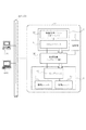
図1は本実施形態における画像処理装置の概略構成の一例を示す図である。 FIG. 1 is a diagram illustrating an example of a schematic configuration of an image processing apparatus according to the present embodiment.
本実施形態において画像処理装置1は、例えば、コピー、スキャン、ファクシミリ、プリントといった複数種類の機能を備えた複合機である。 In the present embodiment, the image processing apparatus 1 is a multifunction machine having a plurality of types of functions such as copying, scanning, facsimile, and printing.
画像処理装置1は、イーサネット(登録商標)等のLAN(Local Area Network)400を介してパーソナルコンピュータ(PC)3、4に接続されている。 The image processing apparatus 1 is connected to personal computers (PCs) 3 and 4 via a LAN (Local Area Network) 400 such as Ethernet (registered trademark).
画像処理装置1は、原稿画像の読取処理を行うリーダ部2と、画像データの印刷出力を行うプリンタ部6を有する。また、画像データや操作画面の表示などを行う液晶パネルを備えた操作部7を備える。 The image processing apparatus 1 includes a reader unit 2 that performs a document image reading process, and a printer unit 6 that performs printing output of image data. In addition, an operation unit 7 including a liquid crystal panel for displaying image data, an operation screen, and the like is provided.
コントローラ110は、上述の各構成要素を接続し、これら構成要素を制御し、画像処理装置1全体の制御を統括する。
The
リーダ部2は原稿用紙を搬送する原稿給紙ユニット(部)10と、原稿画像を光学的に読み取って電気信号としての画像データに変換するスキャナユニット(部)11とを有する。 The reader unit 2 includes a document feeding unit (unit) 10 that transports document paper, and a scanner unit (unit) 11 that optically reads a document image and converts it into image data as an electrical signal.
プリンタ部6は記録用紙を収容する複数段の給紙カセットを備えた給紙ユニット(部)12と画像データを記録用紙に転写、定着するマーキングユニット(部)13を有する。プリンタ部6はさらに、印字された記録用紙にソート処理やステイプル処理を施して、外部に排出する排紙ユニット(部)14とを有している。 The printer unit 6 has a paper feed unit (part) 12 having a plurality of stages of paper feed cassettes for storing recording paper and a marking unit (part) 13 for transferring and fixing image data onto the recording paper. The printer unit 6 further includes a paper discharge unit (unit) 14 that performs sort processing and stapling processing on the printed recording paper and discharges the recording paper to the outside.
図2はコントローラ110のハードウェアブロックの一例を示す図である。
FIG. 2 is a diagram illustrating an example of a hardware block of the
メインコントローラ32は、CPU33とバスコントローラ34と後述する各種コントローラ回路を含む機能ブロックとを内蔵する。 The main controller 32 incorporates a CPU 33, a bus controller 34, and functional blocks including various controller circuits described later.
メインコントローラ32は、ROMI/F35を介してROM36と接続し、DRAMI/F37を介してDRAM38と接続する。 The main controller 32 is connected to the ROM 36 via the ROM I / F 35 and is connected to the DRAM 38 via the DRAM I / F 37.
メインコントローラ32はさらに、コーデックI/F39を介してコーデック40と接続し、ネットワークI/F41を介してネットワークコントローラ42と接続する。 The main controller 32 is further connected to the codec 40 via the codec I / F 39 and connected to the network controller 42 via the network I / F 41.
ROM36は、メインコントローラ32のCPU33で実行される各種制御プログラムや演算データを格納する。第1記憶装置の一例であり、主記憶装置であるDRAM38は、CPU33が動作するための作業領域や画像データを蓄積するための領域として使用される。コーデック40はDRAM38に記憶されたラスターイメージデータをMH/MR/MMR/JBIGなどの周知の圧縮方式で圧縮したり、圧縮されたデータをラスターイメージに伸長する。また、コーデック40にはSRAM43が接続されており、SRAM43は前記コーデック40の一時的な作業領域として使用される。 The ROM 36 stores various control programs executed by the CPU 33 of the main controller 32 and calculation data. A DRAM 38, which is an example of a first storage device and is a main storage device, is used as a work area for the CPU 33 to operate and an area for storing image data. The codec 40 compresses the raster image data stored in the DRAM 38 by a known compression method such as MH / MR / MMR / JBIG, or decompresses the compressed data into a raster image. Further, an SRAM 43 is connected to the codec 40, and the SRAM 43 is used as a temporary work area of the codec 40.
ネットワークコントローラ42は、ネットワークコネクタ44を介してLAN400と接続する。
The network controller 42 is connected to the
また、メインコントローラ32はスキャナバス45を介してスキャナI/F46に接続し、プリンタバス47を介してプリンタI/F48に接続する。さらに、メインコントローラ32は、PCIバス等の汎用高速バス49を介して拡張ボードを接続するための拡張コネクタ50及び入出力制御部(I/O制御部)51に接続する。 The main controller 32 is connected to the scanner I / F 46 via the scanner bus 45 and is connected to the printer I / F 48 via the printer bus 47. Further, the main controller 32 is connected to an expansion connector 50 and an input / output control unit (I / O control unit) 51 for connecting an expansion board via a general-purpose high-speed bus 49 such as a PCI bus.
I/O制御部51はリーダ部2やプリンタ部6との間で制御コマンドを送受信するための調歩同期式のシリアル通信コントローラ52を2チャンネル装備している。 The I / O control unit 51 is equipped with two channels of asynchronous serial communication controllers 52 for transmitting and receiving control commands to and from the reader unit 2 and the printer unit 6.
シリアル通信コントローラ52はI/Oバス53を介してスキャナI/F46及びプリンタI/F48に接続する。 The serial communication controller 52 is connected to the scanner I / F 46 and the printer I / F 48 via the I / O bus 53.
スキャナI/F48は、第一の調歩同期シリアルI/F54及び第一のビデオI/F55を介してスキャナコネクタ56に接続され、さらにスキャナコネクタ56はリーダ部2のスキャナユニット11(図1)に接続されている。そして、スキャナI/F46はスキャナ部11から受信した画像データに対し所望の2値化処理や、主走査方向及び/又は副走査方向の変倍処理を行う。またスキャナ部11から送られてきたビデオ信号に基づいて制御信号を生成し、スキャナバス45を介してメインコントローラ32に転送する。 The scanner I / F 48 is connected to the scanner connector 56 via the first asynchronous serial I / F 54 and the first video I / F 55, and the scanner connector 56 is connected to the scanner unit 11 (FIG. 1) of the reader unit 2. It is connected. The scanner I / F 46 performs desired binarization processing and scaling processing in the main scanning direction and / or sub-scanning direction on the image data received from the scanner unit 11. A control signal is generated based on the video signal sent from the scanner unit 11 and transferred to the main controller 32 via the scanner bus 45.
プリンタI/F48は、第2の調歩同期シリアルI/F57及び第2のビデオI/F58を介してプリンタコネクタ59に接続され、さらに該プリンタコネクタ59はプリンタ部6のマーキングユニット13(図1)に接続されている。そして、プリンタI/F48はメインコントローラ32から出力された画像データにスムージング処理などの画像処理を施して画像データをマーキングユニット13に出力する。さらにマーキングユニット13から送られたビデオ信号に基づいて、生成された制御信号をプリンタバス47に出力する。
The printer I / F 48 is connected to the printer connector 59 via the second asynchronous serial I / F 57 and the second video I / F 58. The printer connector 59 is further connected to the marking unit 13 (FIG. 1) of the printer unit 6. It is connected to the. The printer I / F 48 performs image processing such as smoothing processing on the image data output from the main controller 32 and outputs the image data to the marking
CPU33は、ROM36からROMI/F35を介して読み込んだプログラムを実行する。また、或いは、CPU33は、ハードディスク8または9に格納され、DRAM38にロードされたプログラムを実行する。CPU33は後述するフローチャートを処理するためのプログラム実行の主体となる。例えば、CPUは、ホストコンピュータ3、4から受信したPDL(ページ記述言語)データを解釈し、ラスターイメージデータに展開処理を行う。
The CPU 33 executes a program read from the ROM 36 via the ROM I / F 35. Alternatively, the CPU 33 executes a program stored in the hard disk 8 or 9 and loaded into the DRAM 38. The CPU 33 becomes a main body of program execution for processing a flowchart described later. For example, the CPU interprets PDL (page description language) data received from the
バスコントローラ34は、スキャナI/F46プリンタI/F48、その他拡張コネクタ50等に接続された外部機器から入出力されるデータの転送を制御するものであり、バス競合時のアービトレーション(調停)やDMAデータ転送の制御を行う。即ち、例えば、DRAM38とコーデック40との間のデータ転送や、スキャナユニット11からDRAM38へのデータ転送、DRAM38からマーキングユニット13へのデータ転送等は、バスコントローラ34によって制御される。
The bus controller 34 controls the transfer of data input / output from / to external devices connected to the scanner I / F 46, printer I / F 48, and other expansion connectors 50, and the like. Controls data transfer. That is, for example, data transfer between the DRAM 38 and the codec 40, data transfer from the scanner unit 11 to the DRAM 38, data transfer from the DRAM 38 to the marking
I/O制御部51は、LCDコントローラ60及びキー入力I/F61を介してパネルI/F62と接続する。パネルI/F62は操作部7(図1)に接続する。 The I / O control unit 51 is connected to the panel I / F 62 via the LCD controller 60 and the key input I / F 61. The panel I / F 62 is connected to the operation unit 7 (FIG. 1).
また、I/O制御部51は不揮発性メモリ領域としてのフラッシュメモリ66に接続されている。またI/O制御部51はE−IDEコネクタ63を介して第2記憶装置の一例であるハードディスクドライブ(HDD)8及び9に接続する。HDD8、9には、CPU33が実行するプログラムや、画像データが記憶される二次記憶装置である。HDD8、9に記憶されたプログラムはDRAM38にロードさ、CPU33はDRAM38にロードされたプログラムを実行する。本実施形態ではHDD8、9という2台のハードディスクドライブを備える構成をとっているが、この台数に限る必要は無い。また、複数台のハードディスクドライブによってRAID(Redundant Arrays of Inexpensive Disks)を構成するようにしても良い。また、HDD8または9を、他の不揮発性記憶装置に置き換えてもよい。例えばSSD(Solid State Disk)などを用いてもよい。なお、本実施形態では、HDD8或いは9よりも、DRAM38の方がデータの読み出し、書き込みに必要な時間は短いものとする。 The I / O control unit 51 is connected to a flash memory 66 as a nonvolatile memory area. The I / O control unit 51 is connected to hard disk drives (HDD) 8 and 9 which are examples of the second storage device via the E-IDE connector 63. The HDDs 8 and 9 are secondary storage devices in which programs executed by the CPU 33 and image data are stored. The programs stored in the HDDs 8 and 9 are loaded into the DRAM 38, and the CPU 33 executes the programs loaded into the DRAM 38. In the present embodiment, a configuration including two hard disk drives, HDDs 8 and 9, is adopted, but it is not necessary to limit to this number. Further, a RAID (Redundant Arrays of Inexpensive Disks) may be configured by a plurality of hard disk drives. Further, the HDD 8 or 9 may be replaced with another nonvolatile storage device. For example, an SSD (Solid State Disk) may be used. In this embodiment, it is assumed that the time required for reading and writing data in the DRAM 38 is shorter than that in the HDD 8 or 9.
さらに、I/O制御部51は、機器内で管理する日付と時刻を更新/保存するリアルタイムクロックモジュール64に接続する。 Further, the I / O control unit 51 is connected to a real-time clock module 64 that updates / stores the date and time managed in the device.
尚、リアルタイムクロックモジュール64はバックアップ用電池65に接続し、バックアップ用電池65によりバックアップされている。 The real-time clock module 64 is connected to the backup battery 65 and backed up by the backup battery 65.
次に図3を用いてメモリ制御に関わるプログラムのモジュール構成について説明する。 Next, a module configuration of a program related to memory control will be described with reference to FIG.
図3は、画像処理装置のメモリ制御に関するプログラムモジュールの一例を示す図である。 FIG. 3 is a diagram illustrating an example of a program module related to memory control of the image processing apparatus.
プロセス1001、メモリ管理1002、ログ解析1004、ログ管理1005はROM36もしくはHDD8、9にあらかじめ格納されたプログラムである。CPU33は、ROM36、或いはHDD8、9からプロセスの単位でDRAM38に読み込んだプログラムを実行する。
The
プロセス1001は、画像処理装置を制御するために実行するプログラムの処理の単位である。プロセス1001は実際には複数存在して、CPU33が複数のプロセスを実行することで、画像処理装置1が備える様々な機能(コピー、プリント、FAX、スキャン、等)のジョブを制御することができる。
A
CPU33がプロセス1001を実行するために作業用のメモリ領域が必要になるとDRAM38上の一部の領域を獲得する。以下、特に断りの無い限り、「メモリ領域」とはDRAM38上の記憶領域のことを指すものとする。CPU33は複数のプロセスを実行することができる。複数のプロセスがDRAM38上のメモリ領域を獲得することで、DRAM38の空き領域が不足した場合、あるプロセスがDRAM38上に確保した領域内のデータをハードディスク8、9に一時待避することでDRAM38の空き領域を確保する。このように、実メモリ(DRAM38)の容量を空けるためにあるメモリ領域のデータをハードディスクなどに書き出すことをスワップアウトという。一方、ハードディスクなどに書き出して退避したデータがプログラム処理の都合上必要となったときにDRAM38に書き戻すことをスワップインという。スワップアウト、スワップインによりDRAM38からHDDへ退避したりHDDからDRAM38へ書き戻すデータとしては、プログラムや、プログラムで用いられるデータが含まれる。
When a working memory area is required for the CPU 33 to execute the
なお、本実施形態ではこれらプログラムが動作するためのオペレーティングシステム(OS)としてLinux(登録商標)を用いるものとするが、仮想メモリ管理システムを持つ他のマルチタスクOSでもよい。 In this embodiment, Linux (registered trademark) is used as an operating system (OS) for operating these programs. However, another multitask OS having a virtual memory management system may be used.
本実施形態の画像処理装置のように多数の機能を有するシステムでは、モジュール間の境界としてプロセスを分ける事で、モジュールの堅牢性や再利用性を実現することが一般的に行われている。画像処理装置1は、プロセス分割を適切に行うことで、画像処理装置が持つ機能毎に対応したプロセスが存在することになる。ある機能を使用するジョブを実行する場合には、CPU33はその機能に対応したプロセスを実行する。プロセスの粒度を細分化した場合、複数のプロセスを組み合わせて単一の機能を実現する。 In a system having a large number of functions such as the image processing apparatus according to the present embodiment, it is generally performed to realize robustness and reusability of modules by dividing processes as boundaries between modules. The image processing apparatus 1 appropriately performs process division, so that a process corresponding to each function of the image processing apparatus exists. When executing a job that uses a certain function, the CPU 33 executes a process corresponding to the function. When the process granularity is subdivided, a single function is realized by combining a plurality of processes.
プロセス1001はジョブを実行するたびにログ管理1005へ通知する。
The
メモリ管理1002はプロセス1001へDRAM38上に確保可能なメモリ領域を提供する。
The
プロセス1001は実行に必要なメモリ領域をメモリ管理1002から獲得する。
The
メモリ管理1002が提供するDRAM38上のメモリ領域は、スワップアウト禁止のメモリ領域と通常のメモリ領域との2種類がある。
There are two types of memory areas on the DRAM 38 provided by the
本実施形態では、便宜上、スワップアウトを禁止したメモリ領域を高速メモリ領域、スワップアウトを禁止していない通常のメモリ領域を低速メモリ領域とする。高速メモリ領域はHDD8または9への退避制限がなされた領域となる。 In this embodiment, for convenience, a memory area where swap-out is prohibited is a high-speed memory area, and a normal memory area where swap-out is not prohibited is a low-speed memory area. The high-speed memory area is an area where saving to the HDD 8 or 9 is restricted.
メモリ管理1002はOSが管理するメモリ領域を、プロセスがメモリ領域を獲得するためにOS(Linux)が用意したmmapシステムコールなどにより低速メモリ領域を作成する。
The
メモリ管理1002は通常に獲得したメモリ領域である低速メモリに対して、OSにスワップ禁止領域であることを通知するための機能であるmlockシステムコールを用いて当該領域にスワップ禁止属性を付加すると、スワップアウト禁止の高速メモリを作成する。
When the
OSはDRAM38に空き領域が無い(メモリ枯渇)を検知すると、メモリ領域の中からスワップアウトを実施するのに適したメモリ領域を検索する。スワップアウト禁止属性が設定された高速メモリはOSがスワップ対象メモリ領域を検索する時にスワップ対象から除外されるため、スワップアウトされることはない。一方、スワップアウト禁止属性を設定しない通常の低速メモリは、OSがスワップ対象を検索する時に対象になるため、OSの判断でスワップアウトされる場合がある。高速メモリと低速メモリのサイズ配分はシステム設計段階で一意に定める事ができないため、メモリ管理1002は要求に応じて高速メモリを作り出しプロセス1001に提供する。
When the OS detects that there is no free space in the DRAM 38 (memory exhaustion), the OS searches the memory area for a memory area suitable for performing swap-out. The high-speed memory in which the swap-out prohibition attribute is set is excluded from the swap target when the OS searches the swap target memory area, and is not swapped out. On the other hand, a normal low-speed memory that does not have a swap-out prohibition attribute is a target when the OS searches for a swap target, and may be swapped out based on the judgment of the OS. Since the size allocation between the high-speed memory and the low-speed memory cannot be uniquely determined at the system design stage, the
メモリ管理1002は前記2種類のメモリ領域を、高頻度プロセスリスト1003に基づいて動的に設定する。
The
メモリ管理1002は獲得元のプロセス名を確認する事で高頻度プロセスか否かを判断する。実際には、メモリ管理1002は、ライブラリプログラムとしてプロセス1001に内包された形で動作するため、メモリ管理1002は自分のプロセス名をOSに問い合わせる事でメモリ領域要求元のプロセス名を特定する。
The
高頻度プロセスリスト1003はログ解析1004により高頻度に実行されるプロセスであると特定されたプロセスを登録するリストであり、具体例を図7に示す。高頻度プロセスリスト1003は画像処理装置1のHDD8または9、或いはフラッシュメモリ66のいずれかに記憶される。
The high-
図7の高頻度プロセスリストには、高頻度に実行されるプロセス名がリストされる。実際にはプロセス名の文字列の配列として表現される。高頻度プロセスリスト1003の管理方法としては更新のたびに古いものを破棄する方法と、更新の時に古い高頻度プロセスを残す方法が有り、ユーザや管理者が指定可能である。
In the high-frequency process list in FIG. 7, process names executed frequently are listed. Actually, it is expressed as an array of character strings of process names. As a management method of the high-
古いものを破棄する構成ではログの解析を実施するたびに、その時点での高頻度プロセスで高頻度プロセスリスト1003を上書きする。この場合は、ユーザの使用状況の変動に即座に対応してメモリ管理を実現できる反面、変則的な突発作業があった場合に一時的に効率の悪いメモリ管理をしてしまう可能性がある。一方、古いものを残す構成では高頻度プロセスリスト1003への登録を世代管理しておいて、登録の処理では新規の高頻度プロセスと1世代前の登録分を合わせたものを高頻度プロセスリスト1003へ登録する。
In the configuration in which the old one is discarded, the high-
ログ解析1004はジョブログ1006の解析とジョブプロセステーブル1007の確認をする事で高頻度プロセスを特定し、高頻度プロセスリスト1003へ登録する。
The
使用状況を反映した高頻度プロセスはユーザの使用状況に応じて構成されるが、未使用のシステムに対しては使用履歴が存在しない。この時点での使用に備えて、設計時に選択されたプロセスを高頻度プロセスリストとして作成しておくようにしてもよい。ログ解析1004は予め定められたタイミング、或いは画像処理装置のユーザや管理者が任意に設定したタイミングで実施される。設定としては毎ジョブ実行後、指定時刻が選択可能である。
The high-frequency process reflecting the usage status is configured according to the usage status of the user, but there is no usage history for an unused system. In preparation for use at this point, the process selected at the time of design may be created as a high-frequency process list. The
毎ジョブ実行後に解析を実施すると、ユーザは常に最新の使用状況を反映したメモリ制御が実施された環境で動作できる。 If analysis is performed after each job execution, the user can always operate in an environment in which memory control reflecting the latest usage status is performed.
一方で、別の通常ジョブの実行と同時に解析が行われる可能性が高いため、通常ジョブの実行速度が低下してしまうことがある。 On the other hand, there is a high possibility that the analysis is performed simultaneously with the execution of another normal job, so that the execution speed of the normal job may decrease.
指定時刻に解析を実施すると、ユーザは通常ジョブの実行の妨げにならない時間帯を指定する事ができるため、通常ジョブの実行速度を低下させる事なく機能を使用する事ができる。 If the analysis is performed at the designated time, the user can designate a time zone that does not interfere with the execution of the normal job, and thus the function can be used without reducing the execution speed of the normal job.
一方で、例えば解析を夜間実行した場合などでは、ユーザが使用状況に最適化されたメモリ制御が実施された環境で動作できるのは、翌日以降となる。例えば、日単位で業務プロセスが変動する環境では適切にスループットを改善できない可能性がある。 On the other hand, when the analysis is performed at night, for example, the user can operate in an environment where the memory control optimized for the use situation is performed after the next day. For example, in an environment where business processes fluctuate on a daily basis, there is a possibility that the throughput cannot be improved appropriately.
ログ管理1005はプロセス1001からの通知によりジョブが実行された事をジョブログ1006に記録する。
The
ジョブログ1006はログ管理1005から登録されたジョブ実行履歴を記録する図8に示すようなリストである。ジョブログ1006は画像処理装置1のHDD8または9、或いはフラッシュメモリ66のいずれかに記憶される。実際にはジョブ名の文字列の配列として表現される。
The
ジョブログ1006は、一般的なジョブ履歴としての機能を果たすための付加的な情報を含んでいてもかまわないが、本実施形態では使用しないものとする。付加的な情報は例えば、ジョブ実行時刻などが含まれる。
The
ジョブプロセステーブル1007はジョブの種類(画像処理装置1の備える機能の種類)とプロセスの対応関係を保持する図9に示すようなテーブルである。ジョブプロセステーブル1007は画像処理装置1のHDD8または9、或いはフラッシュメモリ66のいずれかに記憶される。ジョブプロセステーブルは、画像処理装置1の持つ機能とプロセスとを対応付けたジョブプロセス情報の一例である。1つのジョブは複数のプロセスが連携し合うことにより実行される。ジョブプロセステーブル1007はシステムのモジュール構造を設計する際に一意に求まるため、設計時に作成してシステム内に静的な情報として保持される。 The job process table 1007 is a table as shown in FIG. 9 that holds the correspondence between job types (types of functions provided in the image processing apparatus 1) and processes. The job process table 1007 is stored in either the HDD 8 or 9 of the image processing apparatus 1 or the flash memory 66. The job process table is an example of job process information in which functions and processes of the image processing apparatus 1 are associated with each other. One job is executed by cooperation of a plurality of processes. Since the job process table 1007 is uniquely obtained when designing the module structure of the system, it is created at the time of design and held as static information in the system.
ログ解析1004はジョブログ1006を参照して、高頻度に実行されるジョブの種類を特定することができる。そして、ジョブプロセステーブル1007を参照して高頻度に実行されるジョブの実行に必要なプロセスを特定することができ、これを高頻度に実行されるプロセスとして特定し、高頻度プロセスリスト1003へ登録する。高頻度プロセスリスト1003はプロセスの実行頻度を示す情報となる。
The
次に、画像処理装置がジョブを実行するために起動されたプロセス1001がメモリ領域を獲得する処理について説明する。
Next, a process in which the
図4は、画像処理装置1のCPU33が実行するプロセスのメモリ領域獲得処理の一例を示すフローチャートである。本フローチャートは画像処理装置1のCPU33が実行する。 FIG. 4 is a flowchart illustrating an example of a memory area acquisition process of a process executed by the CPU 33 of the image processing apparatus 1. This flowchart is executed by the CPU 33 of the image processing apparatus 1.
ステップ2001で本フローチャートを開始する。メモリ領域の獲得はプロセスやジョブが動作する任意のタイミングで起こりえるため、本フローチャートはプロセスが起動している任意のタイミングで開始する。
In
プロセス1001がメモリ管理1002にメモリ領域を要求する(ステップ2002)。
The
ステップ2003で、メモリ領域を要求されたメモリ管理1002は、要求元プロセスのプロセス名を取得する。プロセス名は文字列形式のデータとして取得する。
In
ステップ2004で、メモリ管理1002は高頻度プロセスリスト1003を読み込む。高頻度プロセスリスト1003は文字列データの配列である。
In
ステップ2005で、メモリ管理1002は、ステップ2002でメモリ領域を要求したプロセス1001が高頻度プロセスであるか否かを判断する。具体的には、ステップ2002でメモリ領域を要求したプロセス1001がステップ2003で取得した高頻度プロセスリストに登録されていれば当該プロセスは高頻度プロセスであると判断し、そうでなければ高頻度プロセスではないと判断する。実際にはステップ2003で得られた文字列と一致するものが、ステップ2004で得られた配列に存在するか確認する処理となる。
In
ステップ2005で、ステップ2002でメモリ領域を要求したプロセス1001が高頻度プロセスであると判断した場合はステップ2006へ進む。
If it is determined in
ステップ2006で、メモリ管理1002は高速メモリを割り当て、メモリ領域を要求したプロセス1001へ割り当てたメモリ領域を提供する。
In
一方、ステップ2005で、ステップ2002でメモリ領域を要求したプロセス1001が高頻度プロセスでないと判断した場合はステップ2009へ進む。
On the other hand, if it is determined in
ステップ2009、メモリ管理1002は低速メモリを割り当て、メモリ領域を要求したプロセス1001へ割り当てたメモリ領域を提供する。
In
ステップ2007で、プロセス1001はメモリ管理1002から提供されたメモリ領域を獲得する。
In
ステップ2008でプロセス1001はメモリ領域獲得に成功している事を条件にメモリ領域獲得フローを終了する。
In
これでプロセス1001はDRAM38上に領域を確保することができ、CPU33はプロセス1001を実行することができる。
Thus, the
そして、プロセス1001は獲得するメモリ領域がスワップ禁止か否かにより処理を切り替える必要はなく、状況に応じて自動的に設定されたメモリ領域を使用する事ができる。
The
次に、画像処理装置のジョブの実行に伴いCPU33が実行したプロセス1001がジョブログを作成する処理について説明する。
Next, a process of creating a job log by the
図5は、画像処理装置1のCPU33が実行するプロセスがログを作成する処理の一例を示すフローチャートである。本フローチャートはCPU33が実行する。
ステップ3001で本フローチャートを実行開始する。ジョブの実行は任意のタイミングで起こりえるため、ジョブの実行に伴い起動するプロセスも任意のタイミングで実行することになり、ログ作成処理のフローも任意のタイミングで実行することになる。
FIG. 5 is a flowchart illustrating an example of a process in which a process executed by the CPU 33 of the image processing apparatus 1 creates a log. This flowchart is executed by the CPU 33.
In
ステップ3002でプロセス1001はジョブの実行を終了する。
In
ステップ3003でプロセス1001はジョブの終了をログ管理1005へ通知する。実際にはジョブの処理の最後でログ管理1005へ通知する処理を実施することで、どのジョブが実行されたかを識別して通知する事ができる。
In
ステップ3004で、ログ管理1005はプロセス1001から通知されたジョブ終了の通知に基づいて、画像処理装置1が実行したジョブのログ(履歴)をジョブログ1006へ履歴記録する。ジョブログ1006が記録するジョブログは図8に示すような情報であり、ジョブログはHDD8または9に記録される。
In
ステップ3005でジョブのログを記録できていることを条件に本フローを終了する。
In
次に、ログ解析1004が高頻度プロセスリストを作成する処理であるログ解析処理について説明する。
Next, log analysis processing, which is processing in which the
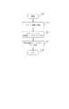
図6は、本実施形態の画像処理装置における高頻度プロセスリスト作成処理の一例を示すフローチャートである。本フローチャートはCPU33が実行する。 FIG. 6 is a flowchart illustrating an example of a high-frequency process list creation process in the image processing apparatus according to the present embodiment. This flowchart is executed by the CPU 33.
ステップ4001で本フローチャートを開始する。本フローチャートは予め設定されたタイミングで開始する。例えば、所定時間おきや、所定回数ジョブを実行した後などが考えられる。これらタイミングは画像処理装置1のユーザや管理者が設定するものとし、設定内容はHDD8または9、或いはフラッシュメモリ66に記憶されているものとする。或いは、予め設定されたタイミング以外に、操作部7を介してユーザや管理者から受け付けた指示に基づいて本フローチャートを実行開始するようにしてもよい。
In
ステップ4002でログ解析1004はジョブログ1006の解析処理を開始する。
In
ステップ4003でログ解析1004はジョブログ1006を読み込む。
In
ステップ4004でログ解析1004は読み込んだジョブログ1006を集計して、実行の頻度が高いジョブの種類を特定する。実際にはジョブログ1006にはジョブの種類を示すジョブ名名の文字列が格納されていて、全てのジョブ名のジョブログ1006での出現回数を数える事でジョブログの集計を行う。そして、ジョブログの集計結果から高頻度ジョブを特定する。高頻度ジョブの特定の仕方としては、例えば、ジョブログの集計結果のうち、所定数以上の出現回数であるジョブを高頻度ジョブとする。また、或いはジョブログの集計結果のうち、最上位、あるいは所定順位以上のジョブを高頻度ジョブとする。
In
そして、ステップ4005で、ログ解析1004はジョブプロセステーブル1007を読み込む。そして、ステップ4006に進み、ログ解析1004は高頻度ジョブに対応するプロセスを特定して高頻度プロセスと判断する。実際にはステップ4004で特定した高頻度ジョブのジョブ名をステップ4005で読み込んだジョブプロセステーブル1007の中から探し、対応する一つ以上のプロセス名を取得する処理を行う。そして、ステップ4007へ進み、ログ解析1004はステップ4006で特定した高頻度プロセスを高頻度プロセスリスト1003へ登録する。実際にはステップ4006で特定した一つ以上のプロセス名で高頻度プロセスリスト1003を上書きする。
In
図7は高頻度プロセスリスト1003の一例を示したものである。高頻度プロセスリスト1003ではシステム内で一意なプロセス名が文字列データとしてリスト形式で表現される。
FIG. 7 shows an example of the high
図8は本実施形態におけるジョブログの一例を示したものである。 FIG. 8 shows an example of a job log in this embodiment.
ジョブログ1006には、画像処理装置1内でジョブの種類を一意に特定するジョブ名と、該当ジョブが実行された時刻がそれぞれ文字列としてリスト形式で表現される。図8の例では、コピージョブ(copy)802、808と、ファクシミリ送信ジョブ(fax_tx)804と、プリントジョブ(pdl)806とがジョブログとして記録されている。もちろん、画像処理装置1が他の種類のジョブを実行すれば、図8に示した以外の種類のジョブ名がジョブログ1006に記録される。
In the
図9は本実施形態におけるジョブプロセステーブルの一例を示したものである。 FIG. 9 shows an example of a job process table in the present embodiment.
ジョブプロセステーブル1007には、画像処理装置1内でジョブの種類を一意に特定するジョブ名と、ジョブ名で特定されるジョブを実行するために必要となる、画像処理装置1内で一意なプロセス名の対応関係がそれぞれ文字列として表形式で表現される。図9の例では、ジョブ名としてコピージョブ(copy)、プリントジョブ(pdl)が登録されており、例えば、コピージョブに対応するプロセス名としては、scan process、print process、imaging processの3つのプロセスが記録されている。なお、図9では図示していないが、ジョブプロセステーブル1007には、コピージョブ、プリントジョブ以外にも、画像処理装置1が実行可能な種類のジョブの各々について、ジョブとプロセスとの対応関係を記録している。 The job process table 1007 includes a job name that uniquely identifies the job type in the image processing apparatus 1 and a process that is unique in the image processing apparatus 1 that is required to execute the job identified by the job name. Each name correspondence is represented in a tabular form as a character string. In the example of FIG. 9, a copy job (copy) and a print job (pdl) are registered as job names. For example, as a process name corresponding to a copy job, three processes of scan process, print process, and imaging process are registered. Is recorded. Although not shown in FIG. 9, the job process table 1007 shows the correspondence between jobs and processes for each type of job that can be executed by the image processing apparatus 1 in addition to a copy job and a print job. It is recorded.
以上、本実施形態によれば、画像処理装置1が実行したジョブの種類毎の頻度によって、高頻度に実行するプロセスを特定し、該特定したプロセスに対しては高速メモリ領域を提供する。これにより、当該プロセスがスワップアウトすることを防止することができるので画像処理装置1のスループットの低下を防止することができる。そして、画像処理装置1の使用状況によって実行するジョブの種類毎の頻度に変化が生じた場合でも、それに応じて高頻度プロセスを適宜特定することができ、高速メモリ領域を提供する対象となるプロセスを動的に変更することができる。これにより、ユーザは使用状況に応じて最適化されたメモリ管理機能のもと、最適なスループットで画像処理装置1の機能を使用する事ができる。 As described above, according to the present embodiment, a process to be executed with high frequency is specified according to the frequency for each type of job executed by the image processing apparatus 1, and a high-speed memory area is provided for the specified process. Accordingly, it is possible to prevent the process from being swapped out, and thus it is possible to prevent a decrease in the throughput of the image processing apparatus 1. Even when the frequency of each type of job to be executed changes depending on the usage status of the image processing apparatus 1, a high-frequency process can be appropriately specified accordingly, and a process that is a target for providing a high-speed memory area Can be changed dynamically. Thereby, the user can use the function of the image processing apparatus 1 with the optimum throughput under the memory management function optimized according to the use situation.
<第2の実施形態>
第1の実施形態では画像処理装置が実行したジョブの種類毎の実行頻度によって高頻度プロセスを特定する構成を説明した。
<Second Embodiment>
In the first embodiment, the configuration has been described in which a high-frequency process is specified based on the execution frequency for each type of job executed by the image processing apparatus.
オフィス内において、画像処理装置は複数のユーザによって共同で使用されることが多い。しかし、画像処理装置が提供する複数の機能(ジョブの種類)のうち、どの機能が頻繁に用いられるかはユーザによって異なることが多い。それは、担当する業務の内容がユーザ毎に異なるので、ユーザが画像処理装置に対して求める機能もユーザ毎に異なるからである。 In an office, an image processing apparatus is often used jointly by a plurality of users. However, which function is frequently used among a plurality of functions (job types) provided by the image processing apparatus often differs depending on the user. This is because the content of the business in charge varies from user to user, and the function that the user requests from the image processing apparatus also varies from user to user.
第2の実施形態では、画像処理装置を共有使用する複数のユーザ間で業務が異なる場合にユーザ毎に高頻度プロセスを最適化する構成を説明する。 In the second embodiment, a configuration will be described in which a high-frequency process is optimized for each user when business is different among a plurality of users who share and use the image processing apparatus.
第2の実施形態において、画像処理装置1のハード構成、メモリ管理に関するプログラム構成は、少なくとも図1、図2に示したものと同一の構成を備えているものとする。図1、図2に無い構成を第2の実施形態の画像処理装置1が備えている場合にはその都度説明する。 In the second embodiment, the hardware configuration of the image processing apparatus 1 and the program configuration related to memory management are assumed to have at least the same configuration as that shown in FIGS. In the case where the image processing apparatus 1 according to the second embodiment has a configuration not shown in FIGS. 1 and 2, it will be described each time.
ユーザは、操作部7を操作してユーザ情報(例えば、ユーザIDとパスワード)を入力する。画像処理装置1は、パネルI/F62を介してユーザ情報を受け付け、CPU33がユーザ情報をチェックするログイン処理(ユーザ認証処理)を実行した上で、複合機の機能を使用する。なお、画像処理装置1がログイン処理を行う場合には、画像処理装置1の外部のディレクトリサーバ(不図示)へ問い合わせを行い、ディレクトリサーバでの認証結果を受信するようにしてもよい。また、ユーザがユーザ情報を操作部7を用いて入力する代わりに、I/O制御部51に接続されるICカードリーダ(不図示)にユーザ情報が記録されたICカードを読み取らせるようにしてもよい。 The user operates the operation unit 7 to input user information (for example, user ID and password). The image processing apparatus 1 accepts user information via the panel I / F 62, and uses a function of the multifunction peripheral after the CPU 33 executes a login process (user authentication process) for checking the user information. When the image processing apparatus 1 performs a login process, an inquiry may be made to a directory server (not shown) outside the image processing apparatus 1 and an authentication result at the directory server may be received. Further, instead of the user inputting user information using the operation unit 7, an IC card reader (not shown) connected to the I / O control unit 51 is made to read the IC card on which the user information is recorded. Also good.
ログイン情報はジョブを表現するデータに含まれるため、ログイン後は処理の任意のステップでログイン情報を参照する事ができる。 Since the login information is included in the data representing the job, the login information can be referred to at any step of the process after login.
プロセス1001は実行するジョブがどのユーザにより実行されたのか、ログイン情報を参照する事で識別できる。
The
図10は第2の実施形態における画像処理装置のメモリ制御に関するプログラムモジュールの一例を示す図である。なお、図10において、図3と同一の構成については図3と同一の符号を付し、説明を省略する。 FIG. 10 is a diagram illustrating an example of a program module related to memory control of the image processing apparatus according to the second embodiment. In FIG. 10, the same components as those in FIG. 3 are denoted by the same reference numerals as those in FIG.
図10において、図3と異なる部分は、ジョブログ1006の代わりにユーザ毎ジョブログ1102を備えている点である。ユーザ毎ジョブログ1102は、画像処理装置1にログインしたユーザ毎にジョブログを管理している。
10 differs from FIG. 3 in that a
そして、図10において、図3の高頻度プロセスリスト1003の代わりにユーザ毎高頻度プロセスリスト1100を備えている。ユーザ毎高頻度プロセスリスト1100は、ログ解析1004がユーザ毎ジョブログ1102を解析した結果として、高い頻度で実行するプロセスである高頻度プロセスを、ユーザ毎に管理している。
In FIG. 10, a high-
画像処理装置1に新たにユーザがログインすると、当該ユーザ用のジョブログがユーザ毎ジョブログ1102に新規に追加され、当該ユーザ用の高頻度プロセスリストがユーザ毎高頻度プロセスリスト1100に新規に追加される。
When a new user logs in to the image processing apparatus 1, a job log for the user is newly added to the
ログインによりCPU33によりユーザ情報が識別されたジョブの実行履歴(ログ)がユーザ毎に管理されたユーザ毎ジョブログ1102に記録され、ユーザ毎ジョブログ1102を解析した結果がユーザ毎高頻度プロセスリスト1100に記録される。
An execution history (log) of a job whose user information is identified by the CPU 33 upon login is recorded in a
プロセス起動時のメモリ領域の割り当てを行う際に使われる高頻度プロセスリストは、ユーザ毎高頻度プロセスリスト1100のうち、そのプロセスを起動するタイミングでログインしているユーザの高頻度プロセスリストであり、これを有効高頻度プロセスリストとする。
The high-frequency process list used when allocating a memory area at the time of starting a process is a high-frequency process list of a user who is logged in at the timing of starting the process in the high-
第2の実施形態における、画像処理装置のCPUが実行するプロセスのメモリ領域獲得処理について説明する。 The memory area acquisition process of the process executed by the CPU of the image processing apparatus in the second embodiment will be described.
第2の実施形態におけるメモリ領域獲得処理は、第1の実施形態における図4のフローチャートの処理とほぼ同様であるが、図4のフローチャートとの違いを説明する。 The memory area acquisition process in the second embodiment is substantially the same as the process of the flowchart of FIG. 4 in the first embodiment, but the difference from the flowchart of FIG. 4 will be described.
即ち、第2の実施形態では、ステップ2004でメモリ管理1002はプロセスを起動してメモリ領域を獲得する際にログインしているユーザに対応した高頻度プロセスリストである有効高頻度プロセスリストを読み込む。これにより、ログインしているユーザ特有の画像処理装置1の使用スタイルに適合した高頻度プロセスを特定することができ、当該プロセスに対してメモリ管理1002は高速メモリを割り当てることができる。
That is, in the second embodiment, in
次に、第2の実施形態における、画像処理装置のジョブログ作成処理について説明する。 Next, job log creation processing of the image processing apparatus in the second embodiment will be described.
第2の実施形態におけるジョブログ作成処理は、第1の実施形態における図5のフローチャートの処理とほぼ同様であるが、図5のフローチャートとの違いを説明する。 The job log creation process in the second embodiment is substantially the same as the process of the flowchart of FIG. 5 in the first embodiment, but the difference from the flowchart of FIG. 5 will be described.
第2の実施形態では、ステップ3003でプロセス1001はログ管理1005へジョブの終了を通知するとともに、どのユーザが実行したジョブであったのか、即ち、ジョブを実行した時点で画像処理装置1にログインしていたユーザのユーザ情報を通知する。
In the second embodiment, in
そして、ステップ3004でログ管理1005は通知されたジョブの終了ログを、ユーザ毎ジョブログ1102中の通知されたユーザ情報に対応するユーザのジョブログへ記録する。
In
次に図11のフローチャートを用いて、ユーザがログインした時に有効高頻度プロセスリストを更新するフローを説明する。図11のフローチャートの各ステップは画像処理装置1のCPU33が実行する。 Next, a flow for updating the effective high-frequency process list when the user logs in will be described with reference to the flowchart of FIG. Each step of the flowchart of FIG. 11 is executed by the CPU 33 of the image processing apparatus 1.
ステップ5001で処理が開始する。
In
ステップ5002において、ユーザからのログインのための操作を受け付け、ユーザ情報を特定し、ログイン処理を行う。ログイン処理は画像処理装置1が稼働中の任意のタイミングで実行する。
In
ステップ5003でユーザ毎高頻度プロセスリスト1100のうち、ログインしたユーザに対応した高頻度プロセスリストを特定する。
In
ステップ5004で、ステップ5003で特定された高頻度プロセスリストを有効高頻度プロセスリストとして定義する。
In
ステップ5005で、有効高頻度プロセスリストを更新した事を条件に有効高頻度プロセスリストを更新するフローは終了する。
In
図11のフローチャートを実行することによって、ログインしたユーザに適した有効高頻度プロセスリストを特定することができる。そして、メモリ管理1002が有効高頻度プロセスリストを参照して高頻度プロセスを特定し、当該高頻度プロセスをスワップアウトさせないメモリ領域(高速メモリ領域)に割り当てることができる。これにより、画像処理装置1はログインしたユーザに最適化したメモリ管理機能のもと、最適なスループットでジョブを実行することができる。
By executing the flowchart of FIG. 11, an effective high-frequency process list suitable for the logged-in user can be specified. Then, the
<他の実施形態>
本発明は、前述した実施形態の各機能を実現するための制御プログラムを、システム若しくは装置に対して直接または遠隔から供給し、そのシステム等に含まれるコンピュータや画像処理装置が該供給されたプログラムコードを読み出して実行することによっても達成される。
<Other embodiments>
The present invention supplies a control program for realizing the functions of the above-described embodiments directly or remotely to a system or apparatus, and the computer or image processing apparatus included in the system or the like is supplied with the program. It is also achieved by reading and executing the code.
従って、本発明の機能・処理をコンピュータや上述の装置で実現するために、該コンピュータや上述の装置にインストールされる制御プログラムのプログラムコード自体も本発明を実現するものである。つまり、上記機能・処理を実現するための制御プログラム自体も本発明の一つである。 Accordingly, since the functions and processes of the present invention are implemented by a computer or the above-described apparatus, the program code itself of the control program installed in the computer or the above-described apparatus also implements the present invention. That is, the control program itself for realizing the functions and processes is also one aspect of the present invention.
その場合、プログラムの機能を有していれば、オブジェクトコード、インタプリタにより実行されるプログラム、OSに供給するスクリプトデータ等、プログラムの形態を問わない。 In this case, the program may be in any form as long as it has a program function, such as an object code, a program executed by an interpreter, or script data supplied to the OS.
プログラムを供給するための記録媒体としては、例えば、フレキシブルディスク、ハードディスク、光ディスク、光磁気ディスク、MO、CD−ROM、CD−R、CD−RWなどがある。また、記録媒体としては、磁気テープ、不揮発性のメモリカード、ROM、DVD(DVD−ROM、DVD−R)、USBメモリなどもある。 Examples of the recording medium for supplying the program include a flexible disk, hard disk, optical disk, magneto-optical disk, MO, CD-ROM, CD-R, and CD-RW. Examples of the recording medium include a magnetic tape, a non-volatile memory card, a ROM, a DVD (DVD-ROM, DVD-R), and a USB memory.
また、プログラムは、クライアントコンピュータのブラウザを用いてインターネット/イントラネットのウェブサイトからダウンロードしてもよい。すなわち、該ウェブサイトから本発明のコンピュータプログラムそのもの、もしくは圧縮され自動インストール機能を含むファイルをハードディスク等の記録媒体にダウンロードしてもよいのである。また、本発明のプログラムを構成するプログラムコードを複数のファイルに分割し、それぞれのファイルを異なるウェブサイトからダウンロードすることによっても実現可能である。つまり、本発明の機能処理をコンピュータで実現するためのプログラムファイルを複数のユーザに対してダウンロードさせるサーバも、本発明の構成要件となる場合がある。 The program may be downloaded from an Internet / intranet website using a browser of a client computer. That is, the computer program itself of the present invention or a compressed file including an automatic installation function may be downloaded from the website onto a recording medium such as a hard disk. It can also be realized by dividing the program code constituting the program of the present invention into a plurality of files and downloading each file from a different website. That is, a server that allows a plurality of users to download a program file for realizing the functional processing of the present invention on a computer may be a constituent requirement of the present invention.
また、本発明のプログラムを暗号化してCD−ROM等の記憶媒体に格納してユーザに配布してもよい。この場合、所定条件をクリアしたユーザにのみ、インターネット/イントラネットを介してウェブサイトから暗号化を解く鍵情報をダウンロードさせ、その鍵情報で暗号化されたプログラムを復号して実行し、プログラムをコンピュータにインストールしてもよい。 Further, the program of the present invention may be encrypted and stored in a storage medium such as a CD-ROM and distributed to users. In this case, only the user who has cleared the predetermined condition is allowed to download the key information to be decrypted from the website via the Internet / intranet, decrypt the program encrypted with the key information, and execute the program. You may install it on
また、コンピュータが、読み出したプログラムを実行することによって、前述した実施形態の機能が実現されてもよい。なお、そのプログラムの指示に基づき、コンピュータ上で稼動しているOSなどが、実際の処理の一部または全部を行ってもよい。もちろん、この場合も、前述した実施形態の機能が実現され得る。 Further, the functions of the above-described embodiments may be realized by the computer executing the read program. Note that an OS or the like running on the computer may perform part or all of the actual processing based on the instructions of the program. Of course, also in this case, the functions of the above-described embodiments can be realized.
さらに、記録媒体から読み出されたプログラムが、コンピュータに挿入された機能拡張ボードやコンピュータに接続された機能拡張ユニットに備わるメモリに書き込まれてもよい。そのプログラムの指示に基づき、その機能拡張ボードや機能拡張ユニットに備わるCPUなどが実際の処理の一部または全部を行ってもよい。このようにして、前述した実施形態の機能が実現されることもある。 Furthermore, the program read from the recording medium may be written in a memory provided in a function expansion board inserted into the computer or a function expansion unit connected to the computer. Based on the instructions of the program, a CPU or the like provided in the function expansion board or function expansion unit may perform part or all of the actual processing. In this way, the functions of the above-described embodiments may be realized.
1 画像処理装置
8 HDD
9 HDD
33 CPU
38 DRAM
1001 プロセス
1002 メモリ管理モジュール
1003 高頻度プロセスリスト
1004 ログ解析モジュール
1005 ログ管理モジュール
1006 ジョブログ
1007 ジョブプロセステーブル
1 Image processing device 8 HDD
9 HDD
33 CPU
38 DRAM
1001
Claims (9)
前記画像処理装置がジョブを実行するためのプログラムを実行可能なプログラム実行手段と、
前記プログラム実行手段がプログラムを実行するための記憶領域を第1記憶装置中に確保するメモリ管理手段と、
前記メモリ管理手段が前記主記憶装置中に確保した記憶領域に記憶された情報を、第2記憶装置へ退避する退避手段と、
ジョブを実行する毎にジョブの実行に関する履歴を記録する履歴記録手段と、
前記複数種類の機能のうち前記履歴記録手段に記録されたジョブの履歴に基づいて特定される機能に関するジョブの実行のために前記メモリ管理手段が前記第1記憶装置に確保した記憶領域を、前記第2記憶装置へ退避しない記憶領域とする退避制限手段と、を備えることを特徴とする画像処理装置。 An image processing apparatus having a plurality of types of functions and capable of executing a job related to any of the plurality of types of functions,
Program execution means capable of executing a program for the image processing apparatus to execute a job;
Memory management means for securing a storage area in the first storage device for the program execution means to execute the program;
Saving means for saving the information stored in the storage area secured in the main storage device by the memory management means to a second storage device;
A history recording means for recording a history of job execution every time the job is executed;
A storage area secured in the first storage device by the memory management unit for execution of a job related to a function specified based on a job history recorded in the history recording unit among the plurality of types of functions, An image processing apparatus, comprising: a retraction restriction unit configured as a storage area that is not retreated to the second storage device.
前記メモリ管理手段は前記プログラム実行手段が実行する複数のプログラムの各々に対応して前記第1記憶装置中に複数の記憶領域を確保し、
前記退避制限手段は前記複数の記憶領域のうち、前記特定された機能に関するジョブを実行するために確保した記憶領域を、前記第2記憶装置へ退避しない記憶領域とすることを特徴とする、請求項1に記載の画像処理装置。 The program execution means can execute a plurality of programs,
The memory management means secures a plurality of storage areas in the first storage device corresponding to each of a plurality of programs executed by the program execution means,
The save restriction unit, of the plurality of storage areas, reserves a storage area reserved for executing a job related to the specified function as a storage area that is not saved to the second storage device. Item 8. The image processing apparatus according to Item 1.
前記退避制限手段は、前記対応付け情報記憶手段を参照して、前記履歴記録手段に記録されたジョブ履歴から得られるジョブの実行頻度に基づいて特定された種類の機能に対応付けられたプログラムの実行のために確保された前記第1記憶装置中の記憶領域を、前記第2記憶装置へ退避しない記憶領域とすることを特徴とする、請求項1に記載の画像処理装置。 Further comprising association information storage means for storing association information, which is information associated with a program executed by the program execution means for executing a function-related job for each of the plurality of types of functions;
The evacuation restriction unit refers to the association information storage unit and stores the program associated with the function of the type specified based on the job execution frequency obtained from the job history recorded in the history recording unit. The image processing apparatus according to claim 1, wherein a storage area in the first storage device reserved for execution is a storage area that is not saved to the second storage device.
前記退避制限手段は、前記プログラム実行頻度情報に基づいて特定されたプログラムのために確保された前記第1記憶装置中の記憶領域を、前記第2記憶装置へ退避しない記憶領域とすることを特徴とする、請求項3に記載の画像処理装置。 Program frequency information generating means for generating program execution frequency information indicating the execution frequency of the program based on the job history recorded by the history recording means and the association information stored by the association information storage means,
The evacuation restriction means sets a storage area in the first storage device reserved for the program specified based on the program execution frequency information as a storage area that is not evacuated to the second storage device. The image processing apparatus according to claim 3.
前記履歴記録手段はジョブの実行に関する履歴として前記ユーザ認証手段が認証しジョブの実行を指示したユーザを特定する情報を記録し、
前記プログラム頻度情報生成手段は、ユーザ認証手段がユーザを認証するごとに認証されたユーザに関するジョブの履歴と前記対応付け情報とに基づいて前記プログラム実行頻度情報を更新することを特徴とする、請求項5に記載の画像処理装置。 User authentication means for authenticating a user who logs in to the image processing apparatus;
The history recording unit records information for identifying a user who has been authenticated by the user authentication unit and instructed to execute a job as a history regarding job execution,
The program frequency information generation unit updates the program execution frequency information based on a history of jobs related to the authenticated user and the association information each time the user authentication unit authenticates the user. Item 6. The image processing apparatus according to Item 5.
前記プログラム実行手段がプログラムを実行するための記憶領域を第1記憶装置中に確保するメモリ管理工程と、
前記メモリ管理工程において前記第1記憶装置中に確保された記憶領域に記憶された情報を、第2記憶装置へ退避する退避工程と、
ジョブを実行する毎にジョブの実行に関する履歴を記録する履歴記録工程と、
前記複数種類の機能のうち前記履歴記録工程で記録されたジョブの履歴に基づいて特定される機能に関するジョブの実行のために前記メモリ管理工程で前記主記憶装置に確保された記憶領域を、前記第2記憶装置へ退避しない記憶領域とする退避制限工程と、を備えることを特徴とする画像処理装置のメモリ管理。 A memory management method for an image processing apparatus, comprising a plurality of types of functions, capable of executing a job related to any of the plurality of types of functions, and comprising a program execution unit capable of executing a program for executing the job,
A memory management step for securing a storage area in the first storage device for the program execution means to execute the program;
A saving step of saving information stored in a storage area secured in the first storage device in the memory management step to a second storage device;
A history recording process for recording a history of job execution every time the job is executed;
A storage area secured in the main storage device in the memory management step for executing a job related to a function specified based on a job history recorded in the history recording step among the plurality of types of functions, A memory management of the image processing apparatus, comprising: a saving limit process for setting a storage area that is not saved to the second storage device.
前記プログラム実行手段がプログラムを実行するための記憶領域を第1記憶装置中に確保するメモリ管理工程と、
前記メモリ管理工程において前記第1記憶装置中に確保された記憶領域に記憶された情報を、第2記憶装置へ退避する退避工程と、
ジョブを実行する毎にジョブの実行に関する履歴を記録する履歴記録工程と、
前記複数種類の機能のうち前記履歴記録工程で記録されたジョブの履歴に基づいて特定される機能に関するジョブの実行のために前記メモリ管理工程で前記第1記憶装置に確保された記憶領域を、前記第2記憶装置へ退避しない記憶領域とする退避制限工程と、を備えることを特徴とする制御プログラム。 An image processing apparatus having a plurality of types of functions, capable of executing a job related to any of the plurality of types of functions, and having a program execution unit capable of executing a program for executing the job, A control program, the memory management method comprising:
A memory management step for securing a storage area in the first storage device for the program execution means to execute the program;
A saving step of saving information stored in a storage area secured in the first storage device in the memory management step to a second storage device;
A history recording process for recording a history of job execution every time the job is executed;
A storage area secured in the first storage device in the memory management step for executing a job related to a function specified based on a job history recorded in the history recording step among the plurality of types of functions, And a saving limit step for setting a storage area that is not saved to the second storage device.
Priority Applications (3)
| Application Number | Priority Date | Filing Date | Title |
|---|---|---|---|
| JP2008160769A JP5213539B2 (en) | 2008-06-19 | 2008-06-19 | Image processing apparatus and memory management method for image processing apparatus |
| US12/485,782 US8854388B2 (en) | 2008-06-19 | 2009-06-16 | Image processing apparatus and memory management method for image processing apparatus |
| CN 200910150625 CN101610337B (en) | 2008-06-19 | 2009-06-19 | Image processing apparatus and memory management method for image processing apparatus |
Applications Claiming Priority (1)
| Application Number | Priority Date | Filing Date | Title |
|---|---|---|---|
| JP2008160769A JP5213539B2 (en) | 2008-06-19 | 2008-06-19 | Image processing apparatus and memory management method for image processing apparatus |
Publications (3)
| Publication Number | Publication Date |
|---|---|
| JP2010003076A true JP2010003076A (en) | 2010-01-07 |
| JP2010003076A5 JP2010003076A5 (en) | 2011-08-04 |
| JP5213539B2 JP5213539B2 (en) | 2013-06-19 |
Family
ID=41430759
Family Applications (1)
| Application Number | Title | Priority Date | Filing Date |
|---|---|---|---|
| JP2008160769A Active JP5213539B2 (en) | 2008-06-19 | 2008-06-19 | Image processing apparatus and memory management method for image processing apparatus |
Country Status (3)
| Country | Link |
|---|---|
| US (1) | US8854388B2 (en) |
| JP (1) | JP5213539B2 (en) |
| CN (1) | CN101610337B (en) |
Cited By (5)
| Publication number | Priority date | Publication date | Assignee | Title |
|---|---|---|---|---|
| JP2012088767A (en) * | 2010-10-15 | 2012-05-10 | Hitachi Solutions Ltd | Updating method for embedded program, update program for embedded program, electronic device, and network system |
| JP2018120376A (en) * | 2017-01-24 | 2018-08-02 | キヤノン株式会社 | Information processing apparatus with nonvolatile storage device and control method of the same |
| JP2019114879A (en) * | 2017-12-22 | 2019-07-11 | 京セラドキュメントソリューションズ株式会社 | Image forming apparatus and information processing program |
| US10353454B2 (en) | 2016-02-04 | 2019-07-16 | Toshiba Memory Corporation | Information processing apparatus and computer program product for changing swap spaces based on a performance threshold |
| US10379746B2 (en) | 2016-02-04 | 2019-08-13 | Toshiba Memory Corporation | Information processing apparatus, storage device, and computer program product |
Families Citing this family (9)
| Publication number | Priority date | Publication date | Assignee | Title |
|---|---|---|---|---|
| CN102104702A (en) * | 2009-12-21 | 2011-06-22 | 株式会社东芝 | Image forming apparatus and image forming method |
| US20130011014A1 (en) * | 2010-03-09 | 2013-01-10 | Jesse Sheng Jin | Surveillance system and method |
| US9489293B2 (en) * | 2012-08-17 | 2016-11-08 | Netapp, Inc. | Techniques for opportunistic data storage |
| KR101694287B1 (en) * | 2013-05-23 | 2017-01-23 | 한국전자통신연구원 | Apparatus and method for managing processing tasks |
| JP6146675B2 (en) * | 2014-06-03 | 2017-06-14 | コニカミノルタ株式会社 | Image forming apparatus, flash memory control method, and control program |
| JP6720824B2 (en) * | 2016-10-17 | 2020-07-08 | コニカミノルタ株式会社 | Image processing device, image processing device control method, and program |
| JP2019067025A (en) * | 2017-09-29 | 2019-04-25 | 京セラドキュメントソリューションズ株式会社 | Image forming apparatus |
| US10992834B2 (en) | 2018-05-17 | 2021-04-27 | Canon Kabushiki Kaisha | Image processing apparatus, method for controlling the same, and computer-readable storage medium |
| JP7186541B2 (en) * | 2018-05-17 | 2022-12-09 | キヤノン株式会社 | IMAGE PROCESSING DEVICE, CONTROL METHOD THEREOF, AND PROGRAM |
Citations (3)
| Publication number | Priority date | Publication date | Assignee | Title |
|---|---|---|---|---|
| JP2000184157A (en) * | 1998-11-13 | 2000-06-30 | Ricoh Co Ltd | Digital copying machine |
| JP2008097425A (en) * | 2006-10-13 | 2008-04-24 | Mitsubishi Electric Corp | Mobile information terminal and control method of mobile information terminal |
| JP2009020555A (en) * | 2007-07-10 | 2009-01-29 | Panasonic Corp | Swapping device |
Family Cites Families (6)
| Publication number | Priority date | Publication date | Assignee | Title |
|---|---|---|---|---|
| JP2004227188A (en) | 2003-01-21 | 2004-08-12 | Fujitsu Ltd | Job swap method, job management device and job management program |
| US20040193855A1 (en) * | 2003-03-31 | 2004-09-30 | Nicolas Kacevas | System and method for branch prediction access |
| US7496722B2 (en) * | 2005-04-26 | 2009-02-24 | Hewlett-Packard Development Company, L.P. | Memory mapped page priorities |
| JP4284332B2 (en) * | 2006-04-21 | 2009-06-24 | 株式会社東芝 | Performance monitoring device, data collection method and program thereof |
| JP4358203B2 (en) * | 2006-05-01 | 2009-11-04 | シャープ株式会社 | Multifunction device, control method of multifunction device, control device, control method of control device, multifunction device control system, control program, and computer-readable recording medium |
| US8250306B2 (en) * | 2008-04-24 | 2012-08-21 | International Business Machines Corporation | Method for improving frequency-based caching algorithms by maintaining a stable history of evicted items |
-
2008
- 2008-06-19 JP JP2008160769A patent/JP5213539B2/en active Active
-
2009
- 2009-06-16 US US12/485,782 patent/US8854388B2/en active Active
- 2009-06-19 CN CN 200910150625 patent/CN101610337B/en active Active
Patent Citations (3)
| Publication number | Priority date | Publication date | Assignee | Title |
|---|---|---|---|---|
| JP2000184157A (en) * | 1998-11-13 | 2000-06-30 | Ricoh Co Ltd | Digital copying machine |
| JP2008097425A (en) * | 2006-10-13 | 2008-04-24 | Mitsubishi Electric Corp | Mobile information terminal and control method of mobile information terminal |
| JP2009020555A (en) * | 2007-07-10 | 2009-01-29 | Panasonic Corp | Swapping device |
Cited By (5)
| Publication number | Priority date | Publication date | Assignee | Title |
|---|---|---|---|---|
| JP2012088767A (en) * | 2010-10-15 | 2012-05-10 | Hitachi Solutions Ltd | Updating method for embedded program, update program for embedded program, electronic device, and network system |
| US10353454B2 (en) | 2016-02-04 | 2019-07-16 | Toshiba Memory Corporation | Information processing apparatus and computer program product for changing swap spaces based on a performance threshold |
| US10379746B2 (en) | 2016-02-04 | 2019-08-13 | Toshiba Memory Corporation | Information processing apparatus, storage device, and computer program product |
| JP2018120376A (en) * | 2017-01-24 | 2018-08-02 | キヤノン株式会社 | Information processing apparatus with nonvolatile storage device and control method of the same |
| JP2019114879A (en) * | 2017-12-22 | 2019-07-11 | 京セラドキュメントソリューションズ株式会社 | Image forming apparatus and information processing program |
Also Published As
| Publication number | Publication date |
|---|---|
| JP5213539B2 (en) | 2013-06-19 |
| CN101610337B (en) | 2011-09-28 |
| US8854388B2 (en) | 2014-10-07 |
| US20090315903A1 (en) | 2009-12-24 |
| CN101610337A (en) | 2009-12-23 |
Similar Documents
| Publication | Publication Date | Title |
|---|---|---|
| JP5213539B2 (en) | Image processing apparatus and memory management method for image processing apparatus | |
| JP4185920B2 (en) | Print control method, print setting management system, and software distribution server | |
| US8176344B2 (en) | Information processing apparatus and control method thereof | |
| US7895373B2 (en) | Electronic device for data access management | |
| EP2765525B1 (en) | Apparatus, non-transitory computer readable information recording medium and information recording method | |
| JP2009199349A (en) | Information processing apparatus, method of controlling therefor, and program | |
| JP5078671B2 (en) | Information processing apparatus, information processing system, and information processing method | |
| US8495364B2 (en) | Image processing apparatus and method using electronic signature information | |
| JP6875808B2 (en) | Information processing device | |
| US8179554B2 (en) | Printer, control method of a printer and computer-readable recording medium | |
| JP5658574B2 (en) | Image forming apparatus, control method therefor, and program | |
| US7509452B2 (en) | Image forming apparatus, erasing method, and hard disk management method | |
| JP2018063676A (en) | Information processing device, control method thereof, and program | |
| JP5414305B2 (en) | Information processing apparatus, virtual storage management method, and program | |
| JP2015204071A (en) | Information processing device, information processing method and program | |
| US11704143B2 (en) | Information processing apparatus, method of controlling the same, and storage medium | |
| JP4959477B2 (en) | Client device, network system, print control method and program | |
| JP4434310B2 (en) | Job processing apparatus, control method for the apparatus, and control program | |
| JP4483996B2 (en) | Job processing apparatus, control method for the apparatus, and control program | |
| JP2006236006A (en) | Printer, program and recording medium | |
| JP2005202890A (en) | Image forming apparatus and method for managing hard disk | |
| JP2017027203A (en) | Storage medium control device, storage medium control program, and storage medium control method | |
| JP2005202889A (en) | Image forming apparatus and method of erasure | |
| KR20070011715A (en) | Image forming device and controlling method thereof | |
| JP2009070208A (en) | Image processing unit and memory allocation method |
Legal Events
| Date | Code | Title | Description |
|---|---|---|---|
| RD04 | Notification of resignation of power of attorney |
Free format text: JAPANESE INTERMEDIATE CODE: A7424 Effective date: 20100201 |
|
| RD01 | Notification of change of attorney |
Free format text: JAPANESE INTERMEDIATE CODE: A7421 Effective date: 20100630 |
|
| A521 | Written amendment |
Free format text: JAPANESE INTERMEDIATE CODE: A523 Effective date: 20110617 |
|
| A621 | Written request for application examination |
Free format text: JAPANESE INTERMEDIATE CODE: A621 Effective date: 20110617 |
|
| A977 | Report on retrieval |
Free format text: JAPANESE INTERMEDIATE CODE: A971007 Effective date: 20120816 |
|
| A131 | Notification of reasons for refusal |
Free format text: JAPANESE INTERMEDIATE CODE: A131 Effective date: 20120911 |
|
| A521 | Written amendment |
Free format text: JAPANESE INTERMEDIATE CODE: A523 Effective date: 20121112 |
|
| TRDD | Decision of grant or rejection written | ||
| A01 | Written decision to grant a patent or to grant a registration (utility model) |
Free format text: JAPANESE INTERMEDIATE CODE: A01 Effective date: 20130129 |
|
| A61 | First payment of annual fees (during grant procedure) |
Free format text: JAPANESE INTERMEDIATE CODE: A61 Effective date: 20130226 |
|
| R151 | Written notification of patent or utility model registration |
Ref document number: 5213539 Country of ref document: JP Free format text: JAPANESE INTERMEDIATE CODE: R151 |
|
| FPAY | Renewal fee payment (event date is renewal date of database) |
Free format text: PAYMENT UNTIL: 20160308 Year of fee payment: 3 |