JP2009539656A - Label supply and label printer - Google Patents
Label supply and label printer Download PDFInfo
- Publication number
- JP2009539656A JP2009539656A JP2009514928A JP2009514928A JP2009539656A JP 2009539656 A JP2009539656 A JP 2009539656A JP 2009514928 A JP2009514928 A JP 2009514928A JP 2009514928 A JP2009514928 A JP 2009514928A JP 2009539656 A JP2009539656 A JP 2009539656A
- Authority
- JP
- Japan
- Prior art keywords
- supply
- label
- tag
- image receiving
- printer
- Prior art date
- Legal status (The legal status is an assumption and is not a legal conclusion. Google has not performed a legal analysis and makes no representation as to the accuracy of the status listed.)
- Pending
Links
Images


Classifications
-
- B—PERFORMING OPERATIONS; TRANSPORTING
- B41—PRINTING; LINING MACHINES; TYPEWRITERS; STAMPS
- B41J—TYPEWRITERS; SELECTIVE PRINTING MECHANISMS, i.e. MECHANISMS PRINTING OTHERWISE THAN FROM A FORME; CORRECTION OF TYPOGRAPHICAL ERRORS
- B41J3/00—Typewriters or selective printing or marking mechanisms characterised by the purpose for which they are constructed
- B41J3/407—Typewriters or selective printing or marking mechanisms characterised by the purpose for which they are constructed for marking on special material
- B41J3/4075—Tape printers; Label printers
-
- B—PERFORMING OPERATIONS; TRANSPORTING
- B41—PRINTING; LINING MACHINES; TYPEWRITERS; STAMPS
- B41J—TYPEWRITERS; SELECTIVE PRINTING MECHANISMS, i.e. MECHANISMS PRINTING OTHERWISE THAN FROM A FORME; CORRECTION OF TYPOGRAPHICAL ERRORS
- B41J3/00—Typewriters or selective printing or marking mechanisms characterised by the purpose for which they are constructed
- B41J3/44—Typewriters or selective printing mechanisms having dual functions or combined with, or coupled to, apparatus performing other functions
- B41J3/50—Mechanisms producing characters by printing and also producing a record by other means, e.g. printer combined with RFID writer
Abstract
画像受け取り用媒体及び、デジタル情報受け取り用タグを含む、ラベルプリンタのためのサプライが提供される。 A supply for a label printer including an image receiving medium and a digital information receiving tag is provided.
Description
本発明は、ラベルプリンタ用のラベルサプライ、ラベルプリンタ、ラベル製造法、に関し、詳しくは、これに限定しないが、RFIDラベルの製造方法に関する。 The present invention relates to a label supply for a label printer, a label printer, and a label manufacturing method, and more particularly, but not exclusively, to a method for manufacturing an RFID label.
ラベルプリンタは既知のものであり、本発明に関連すると考え得る既知形式のテーププリント装置は、EP−A−322918号,EP−A−322919号(何れもブラザー工業株式会社)及びEP−A−267890号(Varitronic)に記載される。これらのプリンターは、カセット又はテープ保持ケースを受けるためのカセット受け用ベイを持つプリント装置を含む。テープ保持ケースは、EP−A−267890号のものではインクリボンと、裏当て層に上側となる画像受け取り層を接着材で固定した基材テープとを収納し、EP−A−322918号及びEP−A−322919号のものでは、インクリボンと、透明な画像受け取り用テープと、両面接着テープとを収納する。この両面接着テープの一方の面には接着材がコーティングされ、プリントされた画像受け取り用テープにこの接着材によって固定されると共に、接着材をコーティングした前記一方の面から剥がせるようにした裏当て層を有している。これらの装置では、画像転写媒体(インクリボン)及び画像受け取り用テープ(基材)とが同じカセットに収納される。 Label printers are known, and known types of tape printers that may be considered relevant to the present invention are EP-A-322918, EP-A-322919 (both Brother Industries, Ltd.) and EP-A-. No. 267890 (Varitronic). These printers include a printing device having a cassette receiving bay for receiving a cassette or tape holding case. In the case of EP-A-267890, the tape holding case accommodates an ink ribbon and a base tape in which an upper image receiving layer is fixed to the backing layer with an adhesive. EP-A-322918 and EP -A-322919 contains an ink ribbon, a transparent image receiving tape, and a double-sided adhesive tape. Adhesive is coated on one side of the double-sided adhesive tape, and the backing is fixed to the printed image receiving tape by the adhesive and can be peeled off from the one side coated with the adhesive. Has a layer. In these apparatuses, the image transfer medium (ink ribbon) and the image receiving tape (base material) are stored in the same cassette.
本件出願人は、例えばEP−A−578372号において、インクリボンと基材テープとを別々のカセットに納めることも提案した。
これら全ての装置では、画像受け取り用テープ(以下、画像受け取り用材料とも称する)はインクリボンと重ねた状態下に、固定のプリントヘッドと、このプリントヘッドを押し付けてインクリボンの画像を画像受け取り用テープに移行させる(又はその逆)プラテンとからなる印刷ゾーンに送られる。インクリボンの画像は、ドライレタリング法又はドライフィルムインプレッション法を含む色々な方法で画像受け取り用テープに移行させ得るが、現在最も一般的なのは、プリントヘッドを加熱し、この熱によってインクリボンのインクを画像受け取り用テープに移行させる熱転写法である。
インクリボンを使用せずにテープ上に画像をプリントすることも知られており、この場合、画像受け取り用テープは感熱性を有し、このテープ上に熱転写ヘッドを使用して画像をプリントする。
The present applicant has also proposed, for example in EP-A-578372, that the ink ribbon and the base tape are stored in separate cassettes.
In all these apparatuses, the image receiving tape (hereinafter also referred to as image receiving material) is stacked with the ink ribbon, and the fixed print head and the print head are pressed to receive the image on the ink ribbon. Sent to a print zone consisting of a platen to be transferred to tape (or vice versa). The ink ribbon image can be transferred to the image receiving tape in a variety of ways, including dry lettering or dry film impression, but currently the most common is to heat the print head and this heat causes the ink ribbon ink to be transferred. This is a thermal transfer method for transferring to an image receiving tape.
It is also known to print an image on a tape without the use of an ink ribbon, in which case the image receiving tape is heat sensitive and the image is printed on the tape using a thermal transfer head.
画像受け取り用テープは連続形態のものであり得、画像をプリントしたテープはラベルプリンタを使用して適当な長さにカットする。画像受け取り用テープが、複数の個別の又はダイカットラベルを担持する裏当て層を含み得ることも知られている。
プリンタは、ポータブル又はデスクトップ用のスタンドアロン型プリンタであり得、あるいは、パソコンその他に接続する構成のものも良い。
The image receiving tape can be in continuous form, and the tape on which the image is printed is cut to an appropriate length using a label printer. It is also known that an image receiving tape can include a backing layer carrying a plurality of individual or die cut labels.
The printer may be a portable or desktop stand-alone printer, or may be configured to connect to a personal computer or the like.
RFIDタグを設けたラベルを含むRFIDラベルは既知のものであり、ラベルプリンタはこのRFIDラベル上にプリントできる。RFIDタグを一体化したダイカットラベルのロールをラベルプリンタに装填し、ラベルプリンタでダイカットラベルのロール上に画像をプリントする。こうした既知のシステムには、RFIDラベルのディメンションが規定されるという欠点がある。ユーザーは、小さいラベルやもっと大きいラベルをプリントしたい時はラベルサプライを変更しなくてはならず、不便である。
例えばオフィス環境では、数多くの、所謂“資産”が利用可能であり且つ多数のユーザー間で共有される。そうした資産には、例えば、共有のラップトップパソコン、コンピューター、スキャナー、プロジェクターがある。こうした装置はその利用状況、特に、誰がいつ利用したかといった状況を把握するのは困難である。
RFID labels including labels with RFID tags are known and label printers can print on this RFID label. A roll of die cut label integrated with an RFID tag is loaded into a label printer, and an image is printed on the roll of die cut label by the label printer. Such known systems have the disadvantage that the dimensions of the RFID label are defined. Users need to change the label supply when they want to print smaller or larger labels, which is inconvenient.
For example, in an office environment, many so-called “assets” are available and shared among many users. Such assets include, for example, shared laptop computers, computers, scanners, and projectors. It is difficult to grasp the state of use of such a device, particularly who used it when.
RFIDラベルは例えば備品管理システムで使用され、既知の備品管理システムには所定の場所にある備品をRFIDラベルを使用して識別するものがあるが、このシステムには備品の位置を特定し難いという欠点がある。十分な位置精度を得るためには所定の場所全体に多数のリーダーを設置する必要があり、費用が掛かる。
別の備品管理システムは、ウェブをベースとし、ユーザー自身がソフトウェアにアクセスして必要な情報を入力又は変更するものであるが、常にそうするわけではない。
RFID labels are used, for example, in equipment management systems, and some known equipment management systems identify equipment in a predetermined location using RFID labels, but this system is difficult to determine the location of equipment. There are drawbacks. In order to obtain sufficient position accuracy, it is necessary to install a large number of readers in a predetermined place, which is expensive.
Another equipment management system is based on the web, where the user himself accesses the software to enter or change the necessary information, but this is not always the case.
解決しようとする課題は、上述した従来装置の問題の1つ以上を解決するラベルサプライ及びラベルプリンタを提供することである。 The problem to be solved is to provide a label supply and label printer that solves one or more of the problems of the prior art devices described above.
本発明によれば、添付する請求の範囲に記載した種々の様相を含むラベルサプライ及びラベルプリンタが提供される。 According to the present invention, there are provided a label supply and a label printer including various aspects described in the appended claims.
図1を参照するに、本発明の第1実施例が略示されている。
リーダー(以下、装置、リーダー装置とも称する)10が設けられ、各リーダー10が、共有備品の1つを使用する個人からの個人識別情報を入手する構成を有している。以下にそうした構成を詳しく説明する。
Referring to FIG. 1, a first embodiment of the present invention is schematically shown.
A reader (hereinafter also referred to as a device or a reader device) 10 is provided, and each
異なる多数の個人が使用できる、所謂“共有”アイテムが参照番号12で略示される。例示目的のみで言えば、これらのアイテムには、コンピューター、ポーターブルコンピューター、ラップトップコンピューター、プロジェクター、スクリーン、モバイルフォン、が含まれ得る。共有アイテムは、本、書類のようなもの、又は家具といったずっと大型のものも含まれ得ることは言うまでもない。これらの各アイテムは属性情報(identity:以下、ID)と関連付けられる。IDはタグに収納される。以下に議論されるように、このタグは任意の好適なフォーマットのものであり得るが、本発明の好ましい実施例ではRFIDタグである。本発明の好ましい実施例では、RFIDタグは装置を識別するための情報を収納する。またRFIDタグには、可視情報を収納するラベルを設け得る。そうした可視情報には、RFIDタグと同じ識別情報が含まれ得る。あるいは、可視情報を収納するラベルに、RFIDタグに含まれるそれに追加する又は別の情報を含ませ得る。
A so-called “shared” item, which can be used by many different individuals, is indicated schematically by
以下に詳しく説明するように、RFIDタグと、可視情報を含むラベルとは装置14によって提供され得る。装置14は、ラベルプリンタを繋ぐパソコンを含む。ラベルプリンタはラベル上に画像をプリントし、RFIDタグにデジタルデータを書き込み、かくして、RFIDタグと可視情報とを含む1枚のラベルを提供する。 As described in detail below, the RFID tag and the label containing the visible information can be provided by the device 14. The device 14 includes a personal computer connecting a label printer. A label printer prints an image on a label and writes digital data to an RFID tag, thus providing a single label that includes the RFID tag and visible information.
ある備品を借りたい場合、ユーザーは自分のIDをリーダー10に登録する。登録された個人IDはインターネットサーバー16に送られる。サーバーはインターネットサーバーでなくとも良く、単にネットワークサーバー又は任意のその他の好適なサーバー、又はパソコンその他でさえもあり得る。個人IDは時間情報及び恐らくは、必ずしもそうしなくとも良いが、備品IDと共に送られる。備品IDはRFIDリーダーを有する装置10によってRFIDタグから入手される。
入手された情報は、装置10のIDと共に、ウェブベースのデータベース18に接続したインターネットサーバー16へと無線リンクを介して送られる。リンクは無線である必要はない。他の実施例ではリーダーはUSBスティックのようなものであり得、このリーダー装置をパソコンに差し込んでパソコンに接続させ得る。データベースはウェブベースのデータベースでなくとも良く、任意のその他の好適なデータベースであり得る。
If a user wants to rent some equipment, the user registers his / her ID in the
The obtained information is sent along with the ID of the
ウェブベースのデータベース18は複数のクライアントコンピューター20又は各パソコンからアクセスできる。従って、ウェブベースのデータベース18は、識別されたユーザーが備品の1つから離れた時間に関する記録を含んでいる。ネットワーク内のクライアントコンピューター20のみならずその他全てのリーダーは、データベースにアクセスすることにより、誰がどの備品を所有しているかを確認できる。
本発明の好ましい実施例では、リーダー10はユーザーからの個人IDを入手可能であり、備品12に取り付けたRFIDタグを読み取れる。しかしながら、本発明の他の実施例では、こうした機能は別の装置によって与えられる。
The web-based
In a preferred embodiment of the present invention,
以下に、図2、図3、図8を参照して装置10を詳しく説明する。図2に示すリーダーはユーザーの個人識別情報を入手できる。個人IDは色々の方法で入手し得るが、本発明の実施例ではリーダーは1つ以上の異なる方法でユーザーからのそうした情報を得ることが可能である。
第1構成はユーザーがIDカードを所有するものである。会社では社員には、例えば特定エリアにアクセスできるようにする情報を収納したIDカードが与えられる。そうした情報は様々な方法でIDカード内に提供される。例えば、カードは情報を含む磁気ストリップを含み得、集積回路又は集積チップを含み得、又は、任意のその他好適な方法によって情報を含み得る。リーダー10は、IDカードを差し込めるスロット24を有する。装置10のリーダーは、ユーザーのIDカード上に収納された情報を、接触機構、走査機構その他の任意の好適な方法で読み取れる。リーダーは、装置に差し込んだIDカードによる識別ができた時はユーザーとの相互対話を行わずにユーザーのIDを読み取る。
Hereinafter, the
In the first configuration, the user owns the ID card. In the company, an employee is given an ID card containing information that enables access to a specific area, for example. Such information is provided in the ID card in various ways. For example, the card may include a magnetic strip that includes information, may include an integrated circuit or an integrated chip, or may include information by any other suitable method. The
あるいはリーダーは、ユーザーが自分の名前及び又はPIN(個人識別番号)コード又は任意のその他識別情報を入力できる入力装置を有する。入力装置は、例えば、キーパッド、タッチスクリーンその他によって提供され得る。リーダーは、ユーザーが自分の名前が出てくるまでスクロールさせ、自分の名前を選択できる名前リストを収納し得る。
ユーザーから生物学的特徴に関する情報(以下、バイオメトリック情報)を得ることが可能である。例えば、リーダーは認定ユーザーの指紋を認識できる指紋認識装置を含み得る。
リーダー10は、ユーザーを識別するために十分な知能を含み得るものとする。本発明の別の実施例では、リーダーはユーザーから得たデータをサーバーその他に送れる。サーバーその他は、リーダー10から受けたデータをプロセス処理してユーザーを認証する。
Alternatively, the reader has an input device that allows the user to enter his name and / or PIN (Personal Identification Number) code or any other identification information. The input device can be provided by, for example, a keypad, a touch screen or the like. The reader may store a name list that allows the user to scroll until their name appears and select their name.
It is possible to obtain information on biological characteristics (hereinafter referred to as biometric information) from the user. For example, the reader may include a fingerprint recognition device that can recognize a fingerprint of an authorized user.
図2には、装置10をシステムに対するインターフェースとして使用する方法が示され、ユーザーに示される色々のメッセージが示されている。図2Aではホーム画面が示され、図2BではユーザーID読み取り後の個人用のウェルカム画面が示される。個人用のウェルカム画面はボタン26を操作することで得られるがこれはオプションである。
図2Cではユーザーは自分自身の認証を求められる。図2に示す実施例では指紋検出法が使用される。本実施例では、ユーザーは自分の指を装置のスクリーン28上に置く。スクリーン28は指紋検出装置を収納する。ボタン26を押して指紋スキャンを開始させる。あるいは、スキャンは時間ベースで開始され得る。
FIG. 2 shows how the
In FIG. 2C, the user is required to authenticate himself. In the embodiment shown in FIG. 2, a fingerprint detection method is used. In this embodiment, the user places his / her finger on the
図2に例示した装置は知能を有し、ユーザーを識別できる。図2DではユーザーのIDを表示するメッセージが表示され、ユーザーは、表示されたIDが正しいことをボタン26を押して確認するよう求められる。図示された装置はスライダ25も有している。スライダは可動部品のない容量型スライダであり得る。ユーザーは、スライダ25を操作して別のオプションを表示させ得る。スライダは垂直方向のものでもあり得る。ボタン26を押すと強調表示されたオプションが選択される。
The apparatus illustrated in FIG. 2 has intelligence and can identify a user. In FIG. 2D, a message displaying the user's ID is displayed and the user is asked to confirm by pressing
ボタンは、簡単なオンクリック機能を持つシンプルなものであり得、あるいは、モバイルフォンで使われるようなジョイスティックタイプのような、もっと複雑で且つユーザーが別のオプションをスキャンし得るようなものでも良い。後者の場合はスライダを省略できる。
本発明の他の実施例では、表示を制御し、オプションを選択するための任意のその他好適な方法を使用可能であることは言うまでもない。
図2Eでは、ユーザーがボタン26を操作してIDが正しいことを確認した時の画面が示される。ユーザーは、借りたい備品をスキャンするように求められる。本発明の好ましい実施例では装置10はRFIDリーダーを有し、ユーザーは借りたい備品のRFIDタグをスキャンするよう求められる。スキャン走査はボタン26を操作して開始させる。
The button can be as simple as a simple on-click function, or it can be more complex and like the joystick type used on mobile phones, allowing the user to scan different options. . In the latter case, the slider can be omitted.
Of course, in other embodiments of the invention, any other suitable method for controlling the display and selecting options may be used.
FIG. 2E shows a screen when the user confirms that the ID is correct by operating the
図2Fでは、スキャン走査が完了し、スキャンされたアイテムが画面上に表示されている。ユーザーは図2Dに関して説明した如きと同様にして、識別された備品が正しいことを確認するよう求められるので、ボタン26を使用してこれを確認する。
図2Gでは、備品が正しいことをユーザーが確認し、ユーザーに次の情報、詳しくは、リーダーから得られる備品の使用期間を表示する情報が提供される。この情報はウェブベースのデータベース18から入手されるが、そのためには、リーダーとデータベース18との間にリンク10を設ける必要がある。リンクは有線又は無線接続を介したものであり得、接続は直接又は非直接接続であり得るが、非直接接続の場合はリーダー装置はデータベースの複製又は部分複製を収納し得る。かくして、ユーザーは備品4の利用可能期間を知れる。ユーザーは、ボタン26を操作し、理解したことを表示させる。
In FIG. 2F, the scan scan is complete and the scanned item is displayed on the screen. The user is prompted to confirm that the identified equipment is correct, as described with respect to FIG. 2D, using
In FIG. 2G, the user confirms that the equipment is correct, and the user is provided with the following information, specifically information indicating the usage period of the equipment obtained from the reader. This information is obtained from the web-based
本発明の1実施例ではデータベースは装置10に記憶される。
図2Hでは、データベースから入手できる備品に関する他の情報、例えば、備品の他の予約者のみならず、その予約時期が示されている。ユーザーはボタン26を操作して当該事項を理解したことを示す。
システム上、あるユーザーがその他のユーザーよりもより多くの情報を見られるようにするアクセス権を定義させ得る。
In one embodiment of the present invention, the database is stored in
In FIG. 2H, other information about the equipment available from the database, for example, the reservation time as well as other reservation persons of the equipment is shown. The user operates the
Access rights can be defined on the system that allow one user to see more information than other users.
図2Iでは、ユーザーが備品の使用可能期間を理解したことの確認を要求するメッセージが示される。この確認もまたボタン26を操作して行う。
図2Jでは、使用上の制限事項を承認したことを確認させるメッセージが示される。ボタン26を操作して次の画面に移動する。
図2Kでは、データベース上でユーザーが、借用した備品と関連づけされていることを示す最終メッセージが表示される。次いで、ユーザーに、期限までに備品を返却することが要求される。
図2に示される各メッセージは例示的なものである。メッセージの正しいフォーマットには種々のものがあり得ることは勿論であり、また、本発明の他の実施例では1つ以上のステップを省略しても良い。
In FIG. 2I, a message is shown requesting confirmation that the user has understood the equipment availability period. This confirmation is also performed by operating the
FIG. 2J shows a message for confirming that the usage restrictions have been approved. The
In FIG. 2K, a final message is displayed indicating that the user is associated with borrowed equipment on the database. The user is then required to return the equipment by the due date.
Each message shown in FIG. 2 is exemplary. Of course, the correct format of the message may vary, and one or more steps may be omitted in other embodiments of the invention.
図2に示すリーダーでは、ユーザーはユーザーのIDに関する情報を入手し、借用備品からのRFIDを読み取り、更には、借用備品に関する任意の関連情報、例えば、利用可能な期間、要メンテナンス時期、等の情報をデータベースから得られる。
こうした機能を別の装置に持たせることも可能である。その場合、集めた情報は図2に関して議論したリーダーの機能を実行可能な単一の装置に送られる。
In the reader shown in FIG. 2, the user obtains information about the user's ID, reads the RFID from the borrowed equipment, and any relevant information about the borrowed equipment, such as available time period, time required for maintenance, etc. Information can be obtained from a database.
It is possible to give such a function to another apparatus. In that case, the collected information is sent to a single device capable of performing the reader functions discussed with respect to FIG.
図8を参照するに、リーダー装置10の構造が略示されている。装置はディスプレイ28を有する。中央にプロセッサ30が設けられる。プロセッサ30はディスプレイドライバ33に接続される。ディスプレイドライバはプロセッサ装置内に埋設される。ディスプレイドライバ33は結局、ディスプレイ28に接続される。プロセッサ30は、ディスプレイ28に表示するメッセージを制御する。
Referring to FIG. 8, the structure of the
プロセッサはRFIDリーダー32に接続される。RFIDリーダーは、備品のRFIDタグを読み取れる。プロセッサはユーザーID入手装置34にも接続される。ユーザーID入手装置34は、指紋検出器、ユーザーがデータを入力できるキーボードを含み得、画面がタッチスクリーンである場合は画面28の一部であり得、又は、カードリーダーあるいは類似の装置リーダーであり得る。ユーザーID装置はID入手装置と同じものであり得、従って、2つの内の何れかのみが設けられる。例えば、ユーザーID情報を、ユーザーのRFIDタグから入手できる。装置は、恐らくは、ウェブベースのデータベース18から情報を受け取るように構成した接続コンポーネントを介した、外部の出力/入力部36をも含み得る。出力/入力部は、有線用ポートまたは無線アンテナその他によって提供され得る。
The processor is connected to the RFID reader 32. The RFID reader can read the RFID tag of the equipment. The processor is also connected to a user
ユーザー入力装置40もまた設けられる。ユーザー入力装置はプロセッサ30に入力される入力情報を提供する。ユーザー入力装置は図2に示すボタン、キーボード、タッチスクリーン、ホイールその他であり得、ある実施例ではユーザーID入手装置34と同じであり得る。
出力部38も設けられる。これによりプロセッサ30は、認証されたユーザー及び又は認証された備品に関連する情報のデータベースに対する要求を出力することが可能となる。出力部38によって、特定の個人による特定備品の予約をデータベース18に送れるようにもなり、かくしてデータベースがアップデートされ得る。
かくして、プロセッサ30は、入力部36を介して受けた情報と、ユーザーID入手装置34からの情報に基づき、画面と、装置の出力部38とを制御する。情報はユーザー入力装置40から受けられ及び又はRFリーダー32から受けられる。
A user input device 40 is also provided. The user input device provides input information that is input to the
An
Thus, the
上述したように、プロセッサに入力を提供する装置の1つ以上は別個に提供され得る。従って、そうした実施例では、プロセッサ30はパソコンその他の一部を構成することになり得る。
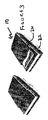
図4Aを参照するに、ラベル材料50のサプライが示され、画像受け取り用の第1層54と、複数のRFIDタグ52とを含んでいる。
図4Bを参照するに、図4Aのラベル材料の概略断面図が示される。
第1層54は画像をプリントする層である。
As discussed above, one or more of the devices that provide input to the processor may be provided separately. Thus, in such an embodiment, the
Referring to FIG. 4A, a supply of
Referring to FIG. 4B, a schematic cross-sectional view of the label material of FIG. 4A is shown.
The
第1層54の裏側には複数のRFIDタグ52が付着される。言い換えると、各RFIDタグは、画像をプリントする側の画像受け取り用の第1層54とは反対側の表面上に設けられる。RFIDタグ52は接着材により第1層54の裏側に積層される。本発明のある実施例ではRFIDタグのICの周囲にフィルター材料58を設け得る。このフィルター材料は画像受け取り用テープの表面を平坦化し、RFIDタグを設けたことによる起伏が生じないようにする機能がある。フィルター材料58は接着材機能も有し得る。
A plurality of RFID tags 52 are attached to the back side of the
裏当て層60が設けられる。裏当て層60と、画像をプリントする第1層54とは、RFIDタグ52を間に挟んだサンドイッチ構造を提供する。裏当て層60をRFIDタグ及び随意的なフィルター材料58に接着させるために好適な接着材が提供される。本発明のある実施例では、裏当て層60の、RFIDタグを設けた側とは反対の側面に接着材層を配置する。この接着材層には剥ぎ取り層62を設ける。この剥ぎ取り層62を除去すると裏当て層60を表面に接着させれるようになる。
A backing layer 60 is provided. The backing layer 60 and the
ある実施例では各層の数は、図4Bに示すそれよりも多い又は少ないものであり得る。例えば、裏当て層60を省略できる。画像をプリントする第1層54の上に更に層を設けることもできる。この追加層はプリントした画像を保護する、所謂、ラミネート層であり得る。ラミネート層は、画像プリント後、又はラベル材料の製造時に設け得る。ラミネート層の場合、画像は第1層54上にではなくむしろ搬送保護層の下側にプリントされ得る。
In some embodiments, the number of each layer can be greater or less than that shown in FIG. 4B. For example, the backing layer 60 can be omitted. Additional layers may be provided on the
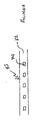
図7を参照するに、カセット306を組み込んだ、本発明を具体化するラベルプリント装置14の平面図が示される。このカセットは、先に議論したような材料のサプライを格納できる。カセット306はカセットベイ316内に位置付けられる。カセットベイ316は、協働して印刷ゾーン302を画定する熱転写プリントヘッド304及びプラテン308の少なくとも一方をも収受する。
プリントヘッド304は、プラテン308との接触状況に持ち来たされてプリントするために、また、プラテン308から離間してカセット306を取り外し且つ交換できるよう、ピボット点324を中心としてピボット廻動できる。プラテン308がその作動位置で回転すると画像受け取り用テープ310がプリントヘッド304を通過して移動する。
Referring to FIG. 7, a plan view of a label printing apparatus 14 embodying the present invention incorporating a cassette 306 is shown. This cassette can store a supply of materials as discussed above. Cassette 306 is positioned in cassette bay 316. Cassette bay 316 also receives at least one of thermal
The
プラテン308は、DCモーター(図6参照)によって駆動されて回転し、かくしてプリント中は画像受け取り用テープがテーププリント装置301の印刷ゾーン302を通過して移動する。
画像は、カラム毎のベースで、各カラムが画像受け取り用テープ310の移動方向に相互に隣り合う状態下に、プリントヘッド304によって画像受け取り用テープ上にプリントされる。各カラムにおける画素は、斯界周知の様式下に画像が形成されるよう選択的に賦活される。DCモーターには、モーターの回転速度を監視するためのシャフトエンコーダーを設ける。モーターの回転速度は、マイクロプロセッサチップ100(図6参照)が、画素データのカラムをプリントヘッド304によってプリントさせるデータストロボ信号を発生することにより制御される。
The
Images are printed on the image receiving tape by the
テーププリント用装置は、ブレード318を担持する切断機構328をその切断位置320に含み得、ブレード318は画像受け取り用テープ310を切断するとカセット306内に位置付けられたスロット330に入る。
画像をプリントする画像受け取り用材料は感熱性のものであり得る。この構成上、画像は画像受け取り用材料(以下、画像受け取り用媒体とも称する)とプリントヘッドの加熱された要素とが接触してプリントされる。リボンは用いない。
The tape printing device may include a cutting mechanism 328 carrying a
The image receiving material on which the image is printed can be heat sensitive. With this arrangement, the image is printed in contact with an image receiving material (hereinafter also referred to as image receiving medium) and a heated element of the print head. Do not use a ribbon.
本発明の別の実施例では、画像受け取り層にインクリボンを付加する必要がある。そうした実施例ではインクリボンを同じカセット内に組み込み得る。この構成上、カセットはインクリボンサプライリールとテークアップスプールとを備える。インクリボンは、プリントヘッドとプラテンとの間で画像受け取り用材料と重なる状態で駆動されるように位置決めされる。インクリボンはプリントヘッドと接触して加熱され、かくして画像受け取り用媒体に画像が記録される。 In another embodiment of the invention, an ink ribbon needs to be added to the image receiving layer. In such embodiments, the ink ribbon can be incorporated into the same cassette. In this configuration, the cassette includes an ink ribbon supply reel and a take-up spool. The ink ribbon is positioned to be driven between the print head and the platen in a state of overlapping the image receiving material. The ink ribbon is heated in contact with the print head, thus recording an image on the image receiving medium.
本発明の他の実施例では、インクリボンは別のカセット内に格納される。
本発明の実施例は、インクジェットプリント、レーザープリント又は任意のその他のプリント技法のような任意のその他の好適なプリント技術と共に使用され得る。
本発明の或る実施例では、画像受け取り用テープのサプライはカセット内には収納されず、単にスプール又はリール上に提供される。
In another embodiment of the invention, the ink ribbon is stored in a separate cassette.
Embodiments of the present invention may be used with any other suitable printing technology, such as inkjet printing, laser printing, or any other printing technique.
In some embodiments of the present invention, the supply of image receiving tape is not stored in a cassette, but is simply provided on a spool or reel.
本発明の他の実施例では、RFIDタグは、画像受け取り用媒体上に画像がプリントされた後に画像受け取り用テープに被着されるように構成される。この方法には3つの利点、即ち、画像をプリントするための、起伏のないスムーズな表面が得られること、ラベルの長さを所望の任意の長さとできること、そして、ラベル毎にRFIDがただ1つ提供されるので経済的であるという利点がある。 In another embodiment of the invention, the RFID tag is configured to be applied to the image receiving tape after the image is printed on the image receiving medium. This method has three advantages: a smooth surface without undulations for printing images, the label length can be of any desired length, and only one RFID per label. Provided, it has the advantage of being economical.
図4A及び4Bに示す構成の場合は、取り扱う画像受け取り用テープが一本であることからラベルプリンタが簡素化されるという利点がある。しかしながら、ラベルプリンタはRFIDタグ間のみが確実に切断されるように、または、少なくとも情報が含まれるタグ部分を切断しないように制御される必要がある。こうした制御は、例えば、画像受け取り用テープの裏側の、RFIDタグ位置に相当する位置にマーキングすることにより実施される。これによりプリンタは、RFIDタグ間にカッターが位置付けられるように画像受け取り用テープを送るべく制御される。 The configuration shown in FIGS. 4A and 4B has an advantage that the label printer is simplified because only one image receiving tape is handled. However, the label printer needs to be controlled so that only the RFID tags are reliably cut, or at least the tag portion including the information is not cut. Such control is performed, for example, by marking a position corresponding to the RFID tag position on the back side of the image receiving tape. This controls the printer to feed the image receiving tape so that the cutter is positioned between the RFID tags.
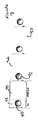
図9を参照するに、RFIDタグ70を画像受け取り用材料72から離間させた第1構成が示される。画像受け取り用材料72はカセット74内に格納される。画像受け取り用材料のサプライはカセットから繰り出され、画像受け取り用材料がプリンタに入ると、プリンタのプラテン308にプリントヘッド304が押し付けられ、かくして画像受け取り用材料に画像がプリントされる。画像受け取り用テープはカッター318で切断する。
図9には、RFIDタグのサプライ76が略示される。これらのRFIDタグは積層又は積み重ね状態で配置される。機構78によってRFIDタグ70を取り出し、このタグを画像受け取り用材料72の、被プリント面とは反対側の表面に被着させる。
Referring to FIG. 9, a first configuration in which the
FIG. 9 schematically shows a supply 76 of RFID tags. These RFID tags are arranged in a stacked or stacked state. The
本発明の1実施例では、画像受け取り用材料の裏側に接着剤が塗布される。接着材はRFIDタグ70を被着せしめるために使用される。この実施例では、画像受け取り用材料の裏側に裏当て層を設け得る。裏当て層は、RFIDタグを被着させる前に、画像受け取り用材料の裏側から部分的に剥ぎ取れる。画像受け取り用材料を完全に切断し、裏当て層を部分的に切断するためのブレード318を設け得る。カッターはそうした切断用の1枚又は2枚のブレードを含み得る。
In one embodiment of the invention, an adhesive is applied to the back side of the image receiving material. The adhesive is used for attaching the
ある実施例では、画像受け取り用テープを剥離(つまり、ライナー層を除去し)してRFIDタグをラベルの粘着性表面に被着させ、その後、剥離したライナー層を貼り戻す又は別のライナー層を貼り重ねる。
図10には、図9のRFIDタグのサプライの改変例が示される。図10の構成では、RFIDタグのサプライ76はカセットの内部に画像受け取り用材料のサプライと共に設けられる。カセット80内には画像受け取り用材料72のサプライが配置される。RFIDタグ70はこの実施例においても積層され、例えば管の各側部によって案内される。カセットは、ラベルプリンタによって起動され、RFIDタグを分与させて画像受け取り用テープの、画像をプリントする側とは反対側の表面に被着させるための簡単な機構を有する。
In one embodiment, the image receiving tape is peeled off (ie, the liner layer is removed) to apply the RFID tag to the adhesive surface of the label, and then the peeled liner layer is applied back or another liner layer is applied. Paste.
FIG. 10 shows a modification of the RFID tag supply of FIG. In the configuration of FIG. 10, an RFID tag supply 76 is provided inside the cassette along with a supply of image receiving material. A supply of
プリンタは2つのモード、即ち、RFIDタグ付きのラベルを作製するモードと、RFIDタグ無しのラベルを作製するモードとを有し得る。各モードはユーザー入力を介して、又はRFIDタグサプライの検出をベースとする自動判定によって制御され得る。
先の実施例と同じように、画像受け取り用テープ及びRFIDタグの一方又は両方に画像受け取り用テープ及びRFIDタグが相互に接着するような接着材が設けられる。
The printer can have two modes: a mode for producing labels with RFID tags and a mode for producing labels without RFID tags. Each mode can be controlled via user input or by automatic determination based on detection of RFID tag supply.
As in the previous embodiment, one or both of the image receiving tape and the RFID tag is provided with an adhesive material for adhering the image receiving tape and the RFID tag to each other.
図11を参照するに、RFIDタグのサプライの別構成が示される。この構成ではRFIDタグ70は裏当て層82上に設けられ、RFIDタグ70と裏当て層82との間部分には、各RFIDタグ70が裏当て層上で然るべく維持されるが、同時に、裏当て層から剥ぎ取られ得るようする接着材が設けられる。
図12を参照するに、図11に示したようなRFIDタグのサプライを組み込んだカセット84が示される。画像受け取り用テープ72のサプライが設けられる。画像受け取り用材料72はプリントヘッド304とプラテン308との間を通過し、プリントヘッド304が、プラテン308に押し付けられて画像がプリントされる。
Referring to FIG. 11, another configuration of the RFID tag supply is shown. In this configuration, the
Referring to FIG. 12, a cassette 84 incorporating a supply of RFID tags as shown in FIG. 11 is shown. A supply of
カセットは、RFIDタグ70のサプライを載置した裏当て層82から成る材料83のサプライ86をも有する。RFIDタグを取り外した裏当て層82のための被駆動型のテークアップスプール88が設けられる。
カセット内には、テーププリンタのローラー92に押し当てられて作用するロール90が設けられる。画像をプリントされた画像受け取り用テープ72は2つのローラー、即ちローラー90及びローラー92間を通過する。更に、テークアップスプール88が必要に応じて駆動され、これらのローラー90及び92間にRFIDタグを通す。これにより、画像受け取り用材料72の、画像をプリントした面と反対側の表面にRFIDタグ70が被着される。
RFIDタグ付きの画像受け取り用テープは、2つのローラー90及び92の下流側で切断され得る。切断機構はラベルプリンタに設けられる。
The cassette also has a supply 86 of material 83 consisting of a backing layer 82 on which a supply of RFID tags 70 is placed. A driven take-up spool 88 is provided for the backing layer 82 from which the RFID tag has been removed.
In the cassette, there is provided a roll 90 that is pressed against a
The image receiving tape with the RFID tag can be cut downstream of the two
本発明の好ましい実施例では、ローラー90及び92の少なくとも一方が他方に向けて可動とされる。従って、画像をプリントする際は2つのローラーが相互に離間され得、他方、RFIDタグを被着させる時は、少なくとも一方のローラーを他方に向けて移動させ、テークアップスプール88を起動してローラー90とローラー92との間でRFIDタグを駆動させ得る。
ローラー90及び92は何れもラベルプリンタ内に設け得るものとする。ローラー90及び92の一方を、壁その他の如き平坦な表面によって代替させても良い。
In a preferred embodiment of the invention, at least one of the
Both
テークアップスプール88はカセット内ではなくむしろラベルプリンタ内に設けられる。
本発明のある実施例ではRFIDタグのサプライは別のカセット内に設けられる。
本発明の更に他の実施例では、画像受け取り用材料72と、RFIDタグのサプライ83とを単一のカセット内に格納するのではなく、スプール上に設けられる。
Take-up spool 88 is provided in the label printer rather than in the cassette.
In one embodiment of the invention, the RFID tag supply is provided in a separate cassette.
In yet another embodiment of the present invention, the
本発明の更に他の実施例では、画像受け取り用テープは、RFIDタグをスプール又はリール上に保持させた状態下にカセット内に受けられる。
RFIDインレイを別のカセット内に格納させ、このカセットから供給されるようにできる。この場合、3つのカセットを含むカセットシステムが含まれ得る。これにより、エンドユーザーに対する融通性がより高まる。本件出願人のEP03795979.8号を参照するに、3つのパーツ(テープ、リボン、RFIDインレイ)を相互に合わせた場合に実際にラベルが作製され得ることをチェックするために使用することのできる互換性チェックを実施する方法が記載される。
In yet another embodiment of the invention, the image receiving tape is received in a cassette with the RFID tag held on a spool or reel.
The RFID inlay can be stored in a separate cassette and supplied from this cassette. In this case, a cassette system including three cassettes may be included. This further increases flexibility for the end user. Referring to Applicant's EP 03799599.8, a compatibility that can be used to check that a label can actually be made when the three parts (tape, ribbon, RFID inlay) are brought together. A method for performing a sex check is described.
図9、図10及び図11に示す各実施例における、プラテンとプリントヘッドの位置は、本発明のこれらの実施例の理解を支援するために略示されたものであるが、画像受け取り用テープに関するプリントヘッドの位置は、画像受け取り用テープの画像印刷面に異存するものである。かくして、本発明の好ましい実施例では、RFIDタグは、画像受け取り用テープの画像印刷面とは反対側に被着される。 The position of the platen and print head in each of the embodiments shown in FIGS. 9, 10 and 11 is shown schematically to assist in understanding these embodiments of the present invention. The position of the print head is different from the image printing surface of the image receiving tape. Thus, in a preferred embodiment of the present invention, the RFID tag is attached to the opposite side of the image receiving tape from the image printing surface.
本発明のある実施例では、図9、図10及び図12に示されるカセットにはインクリボンを追加的に組み込み得る。本発明の他の実施例では、インクリボンを収納した別のカセットを設け得る。本発明の更に他の実施例では1つのテープカートリッジ内にインクリボンとRFIDタグとを設け得る。 In some embodiments of the present invention, an ink ribbon may be additionally incorporated into the cassette shown in FIGS. In other embodiments of the invention, a separate cassette containing the ink ribbon may be provided. In still another embodiment of the present invention, an ink ribbon and an RFID tag may be provided in one tape cartridge.
図13を参照するに、本発明の更に他の実施例が示され、本実施例では裏当て層90が設けられている。この裏当て層90には複数の個別のラベル92が被着される。これらのラベルは所謂“ダイカット”ラベルである。各ラベル上にはRFIDタグ70が設けられ、かくして、ラベル92は2つのゾーン、即ち、RFIDタグが被着されてラベルのリード部分となり得る第1ゾーン93と、画像を印刷する第2ゾーン95とを有する。本発明の1改変例では、RFIDタグがラベルの反対側の面に設けられ、従って、画像を印刷するゾーンがダイカットラベル92の全長を越えて伸延される。
Referring to FIG. 13, yet another embodiment of the present invention is shown, in which a backing layer 90 is provided. A plurality of
図13に示すダイカットラベルのサプライはカセット内に収納され得、又は、他の実施例ではサプライスプール上に設け得る。
本発明の各実施例において、RFIDタグは一回だけ書き込み可能なものであり、他の実施例では、多数回書き込みできるものであり得る。
The supply of die cut labels shown in FIG. 13 can be housed in a cassette, or in other embodiments can be provided on a supply spool.
In each embodiment of the present invention, the RFID tag can be written only once, and in other embodiments, it can be written many times.
本発明のある実施例では読み取り専用タグを有し得る。本発明の好ましい実施例ではRFIDタグは書き込み可能なものであるが、必ずしもそうする必要はない。読み取り専用のRFIDタグは、RFIDタグ製造者の技術的理由から設定される一意の識別番号を常に有している。この番号は、システム上、資産データベースで使用するものとして十分なものである。
本発明の各好ましい実施例で使用するRFIDタグは任意の好適なフォーマットのものであり得る。本発明の実施例で使用可能なRFIDタグの一例は、“Texas Instruments tag-it(商標名)HF-I Standard Transponder Inlays"である。
Some embodiments of the invention may have read-only tags. In the preferred embodiment of the invention, the RFID tag is writable, but this is not necessary. Read-only RFID tags always have a unique identification number set for the technical reasons of the RFID tag manufacturer. This number is sufficient for use in the asset database on the system.
The RFID tags used in each preferred embodiment of the present invention can be of any suitable format. An example of an RFID tag that can be used in an embodiment of the present invention is “Texas Instruments tag-it (trade name) HF-I Standard Transponder Inlays”.
本発明の実施例をRFIDタグを使用するものとして説明したが、本発明の実施例はそれらに限定されるものではない。タグとして、例えば、EPROM、チップその他のような異なる技法ものものを使用できる。タグへの読み書きに使用する周波数は無線周波数、紫外線、赤外線、又は任意のその他の好適な周波数であり得る。タグは、可視読み取り可能な、例えば、2Dバーコードであり得るが、資産は箱又は袋の中にあるので、スキャンに先立ってそれらを開ける必要のないよう、見なくとも読み取れるものであることが好ましい。
本発明を具体化するラベルプリンタを略示する図14を参照されたい。
Although the embodiments of the present invention have been described as using RFID tags, the embodiments of the present invention are not limited thereto. The tags can be of different techniques such as EPROM, chip, etc. The frequency used to read and write to the tag can be radio frequency, ultraviolet, infrared, or any other suitable frequency. The tags may be visible readable, eg 2D barcodes, but the assets are in a box or bag so that they can be read without looking at them so that they do not need to be opened prior to scanning. preferable.
Please refer to FIG. 14, which schematically illustrates a label printer embodying the present invention.
続き番号下に多数の物品をラベル付けしたい場合がしばしばある。従って、本発明の各実施例では、ある範囲の続き番号を選択し、そうした続き番号の1つを含む個別のラベルを自動的にプリントアウトすることが可能である。RFIDタグは、相当する番号を含むように自動的にプログラム化され得る。そうしたシステムを使用してファイル、書類その他を作製できる。
本発明の各実施例は、RFタグに情報を書き込むように構成され得る。RFタグは、例えば有効期限を有するようにプログラム化され得る。例えば、備品の特定をオフィスで使用する場合は、RFID検出器を色々の位置に位置決めできる。従って、ユーザーが備品を有効期限を越えて所有している場合は可聴の警報が鳴り、又はその旨のメッセージがユーザーに送られ得る。
Often you want to label a large number of items under a serial number. Thus, embodiments of the present invention can select a range of serial numbers and automatically print out individual labels containing one of those serial numbers. RFID tags can be automatically programmed to include corresponding numbers. Such a system can be used to create files, documents and others.
Each embodiment of the present invention may be configured to write information to an RF tag. The RF tag can be programmed to have an expiration date, for example. For example, when using fixture identification in an office, the RFID detector can be positioned in various positions. Thus, if the user owns equipment beyond the expiration date, an audible alarm may sound or a message to that effect may be sent to the user.
本発明の1実施例では、ウェブベースのデータベースが、備品の1つの返却日を表示する情報を有する。この日付を過ぎるとサーバーがメッセージを自動生成し、これをユーザーに送る。メッセージはオプションとしての、Eメール、テキストメッセージ、又は任意のその他の好適な手段の形態下に送付され得る。Eメールは、インターネットサーバーがメッセージを生成し、これをユーザーに正しく送付することが可能であることから、オプションとして好ましいものである。
1変形例では、ユーザーに、備品を所定時間までに返却させる警告が与えられる。有効期限後にも備品を利用可能である場合は、備品の使用期間を延長するオプションがユーザに与えられ得る。
In one embodiment of the present invention, a web-based database has information to display one return date for equipment. After this date, the server automatically generates a message and sends it to the user. The message may optionally be sent in the form of an email, text message, or any other suitable means. Email is an optional option because it allows the Internet server to generate a message and send it correctly to the user.
In one variation, the user is warned to return the equipment by a predetermined time. If the equipment is still available after the expiration date, the user may be given the option to extend the equipment usage period.
本発明の更に他の変形例では、ウェブベースのデータベースを使用して特定の1つの備品の次の時間枠を予約したユーザー用のメッセージを生成させ得る。このメッセージは、例えば、備品の現在の所有者を表示できる。
先に説明したように、本発明の各実施例は備品以外の物品に対しても使用可能である。例えば、本発明の各実施例を使用して、ドキュメントセンター又はライブラリ内の本を管理できる。別の実施例ではファイルを管理できる。
In yet another variation of the invention, a web-based database may be used to generate a message for a user who has reserved the next time frame for a particular piece of equipment. This message can, for example, display the current owner of the equipment.
As described above, each embodiment of the present invention can be used for articles other than equipment. For example, embodiments of the present invention can be used to manage books in a document center or library. In another embodiment, files can be managed.
本発明の各実施例が、共有又は共通の備品を多数の異なるユーザーが利用可能であるシステムに関して説明された。本発明の各実施例は、それらの各備品を区別するための物品をラベル付けするために使用可能である。例えば、ある組織内の多数のユーザーに同じ備品が提供され得る。ラベルは、そうした備品に、特定ユーザーとの関連を示す何らかの識別情報を持たせるために使用され得る。
ユーザーは、リーダー装置を使用してRFIDタグを読み取ることで備品の1つを素早く見つけられる。
Each embodiment of the present invention has been described with reference to a system in which shared or common equipment is available to many different users. Each embodiment of the present invention can be used to label articles to distinguish their respective fixtures. For example, the same equipment can be provided to multiple users within an organization. Labels can be used to give such fixtures some identifying information that indicates their association with a particular user.
The user can quickly find one of the fixtures by reading the RFID tag using a reader device.
本発明の他の実施例ではネットワーク内の備品がラベル付けされる。備品には、本発明を具体化するラベルが貼付される。これにより、ネットワークの管理者又はユーザーは特定の1つの備品を識別し、RFIDタグを使用してこの1つの備品を物理的に位置付け、かくしてその場所を知ることができる。ネットワークでは、多数の異なるプリンタに印刷させることがしばしば可能である。特定のプリンタは、その他の多数のプリンタにはない機能をしばしば有し得る。従って、ユーザーはこの特定のプリンタを選んでその機能を利用できる。説明した実施例によればユーザーは、自分の書類を印刷したプリンタを物理的に位置付けるべく、特定のプリンタの位置を素早く決定できる。更には、物品はネットワーク内で移動され得るが、ユーザーはやはり、その物理的位置を容易に特定できる。
本発明の実施例がウェブベースのデータベースに関して説明された。データベースは任意の好ましいフォーマットで提供され得、ネットワーク内の多数の異なる人々がアクセスし得るように構成され得る。本発明の別の実施例では、データベースは、恐らくは唯一人がアクセスする単独位置に保持され得る。
In another embodiment of the invention, the equipment in the network is labeled. A label embodying the present invention is affixed to the fixture. This allows a network administrator or user to identify a particular piece of equipment and physically locate that piece of equipment using an RFID tag, thus knowing its location. In a network, it is often possible to have many different printers print. Certain printers often have functions that are not found in many other printers. Therefore, the user can select this specific printer and use its function. According to the described embodiment, the user can quickly determine the position of a particular printer in order to physically locate the printer that printed his document. Furthermore, although the article can be moved within the network, the user can still easily identify its physical location.
Embodiments of the present invention have been described with respect to web-based databases. The database can be provided in any preferred format and can be configured to be accessible to many different people in the network. In another embodiment of the present invention, the database may be maintained in a single location that is probably the only person accessible.
本発明の各実施例において、ある特定環境が多数のRFID検出器を有し得、例えば、ある範囲の特定の部屋がそのドア上にRFID検出器を有し得る。これらの検出器を通過する物品は登録され、環境内での装置の移動がデータベース上に記録され得る。
図14を参照するに、本発明を具体化するラベルプリンタの詳細が例示されている。本発明の好ましい実施例は、パソコンその他に接続されるように構成したラベルプリンタ150である。従って、ラベルプリンタではパソコンで使用するようなディスプレイ又はキーボードは不要である。図14に示すラベルプリンタ150はカセット受け用ベイ152を含み、このベイ内には画像受け取り用テープ及びRFIDタグのサプライとが受けられる。先に議論したように、画像受け取り用材料及びRFIDタグのサプライは共通のカセット内、別個のカセット内、サプライリール上、又はそれらの組み合わせにおいて設け得る。
In each embodiment of the invention, a particular environment may have multiple RFID detectors, for example, a range of specific rooms may have RFID detectors on their doors. Articles passing through these detectors can be registered and the movement of the device within the environment can be recorded on a database.
Referring to FIG. 14, details of a label printer embodying the present invention are illustrated. A preferred embodiment of the present invention is a label printer 150 configured to be connected to a personal computer or the like. Therefore, the label printer does not require a display or keyboard used in a personal computer. The label printer 150 shown in FIG. 14 includes a
図14に示すプリンタ150は、テープに画像をプリントした後、必要なデジタル情報を書き込んだRFIDタグを含むラベルを送通させるスロット154を有する。
プリンタ150はメモリーカード、メモリースティック、又はスマートカードを差し込めるメモリーカードスロット156を有する。
メモリーカードは装置10によってカードに書き込まれたデータを含み得る。
従って、プリンタ150はRFIDタグに書き込み、ラベル上に印刷されるべきデータをスマートカードその他から入手できる。
The printer 150 shown in FIG. 14 has a
The printer 150 has a
The memory card may contain data written to the card by the
Thus, the printer 150 can write to the RFID tag and obtain data to be printed on the label from a smart card or the like.
あるいは、ラベルプリンタ150を接続するパソコンがウェブベースのデータベースに接続される。これにより、所望の情報をラベル上に印刷することが可能となる。
別の実施例では、プリンタはウェブサーバーを含み得る。そうしたプリンタはネットワーク対応性の有る、例えば、イーサネット(登録商標)接続部を有している。データベースはプリンタのメモリ内に存在し、TCP/IPプロトコルを介して、このプロトコルをサポートする任意のコンピューターからアクセス可能である。
あるいは、装置10ラベルプリンタ150とを接続し、情報を装置10からラベルプリンタに送れる。
Alternatively, a personal computer to which the label printer 150 is connected is connected to a web-based database. Thereby, desired information can be printed on the label.
In another embodiment, the printer may include a web server. Such a printer has network compatibility, for example, an Ethernet (registered trademark) connection. The database resides in the printer's memory and is accessible via any TCP / IP protocol from any computer that supports this protocol.
Alternatively, the
図5には本発明に従うラベル印刷装置14の別態様の実施例の概略ダイヤグラム図が示される。ラベル印刷装置はキーボード130と、カセット受け用ベイ132とを含む。キーボードは、数字、文字を記したような複数のデータ入力キー134及び、ラベルとして印刷するデータを入力する句読点キー、入力データを編集するファンクションキー、を有する。キーボードは、ラベルを印刷したいときに操作するプリントキー136も有し得る。また、テープ印刷装置のオンオフを切り換えるためのオンオフキー138も設け得る。
FIG. 5 shows a schematic diagram of another embodiment of the label printing apparatus 14 according to the present invention. The label printing apparatus includes a
テープ印刷装置は、入力されたデータを表示する液晶ディスプレイ(LCD)140を有する。ユーザーはディスプレイにより、印刷されるラベルの全体又は一部を見れるので、印刷前にラベルを編集しやすくなる。ディスプレイはディスプレイドライバ(図示せず)によって駆動される。
図6にはラベル印刷装置10を制御するための基本回路が示される。読み取り専用メモリ(ROM)202と、マイクロプロセッサ201とを有するマイクロプロセッサチップ200が示され、ランダムアクセスメモリ容量がRAM204としてダイヤグラム表示されている。マイクロプロセッサチップ200は、キーボード206のようなデータ入力装置からのラベルデータ入力を受けるように接続され、ディスプレイドライバチップ209を介してディスプレイ208を駆動し、印刷するラベル(又はその一部)及び又はユーザー用のメッセージをディスプレイ上に表示させる。あるいはディスプレイドライバはマイクロプロセッサチップの一部を構成し得る。更には、マイクロプロセッサチップ200は、ラベルデータを画像受け取り用テープ上に印刷させてラベルを製造するようにプリントヘッド216を駆動するデータも出力する。マイクロプロセッサチップ200は、プラテンを駆動するモーター207をも制御する。マイクロプロセッサチップ200は、切断機構をも制御してある長さでテープを切断させる。別の実施例では、切断機構の少なくとも一部分が手動で操作され得る。
The tape printer has a liquid crystal display (LCD) 140 that displays input data. The display allows the user to see all or part of the printed label, making it easier to edit the label before printing. The display is driven by a display driver (not shown).
FIG. 6 shows a basic circuit for controlling the
基本回路には、RFIDタグにデータを書き込み及び又はRFIDタグからデータを読み取ることのできるRFIDリーダーライター203をも含む。
本発明のテーププリンタがスタンドアロン型のプリンタではなくむしろパソコン用プリンタである場合、データをパソコン側で入力及び表示できるので、キーボード及びディスプレイ手段は不要である。この場合、パソコンはプリンタ用の入力装置として作用する。あるいは印刷用のデータをその他の装置を使用してプリンタに入力できる。例えば、本発明のある実施例では、デジタルカメラ又はモバイルフォンを使用して印刷用データをテープ印刷装置に入力できる。あるいはスマートカード、チップカード、メモリーカードその他を使用して画像を入力できる。
本発明のある実施例では、テーププリンタがパソコンに接続され得る。そうした実施例では、テーププリンタはキーボード又はディスプレイを持たないが、ある実施例ではテーププリンタにはディスプレイ及びキーボードが追加され得る。
The basic circuit also includes an RFID reader /
When the tape printer of the present invention is not a stand-alone printer but rather a personal computer printer, data can be input and displayed on the personal computer side, so that a keyboard and display means are unnecessary. In this case, the personal computer acts as an input device for the printer. Alternatively, printing data can be input to the printer using another device. For example, in one embodiment of the present invention, printing data can be entered into a tape printer using a digital camera or mobile phone. Alternatively, images can be input using smart cards, chip cards, memory cards and others.
In some embodiments of the present invention, a tape printer can be connected to a personal computer. In such an embodiment, the tape printer does not have a keyboard or display, but in some embodiments a display and keyboard may be added to the tape printer.
10 リーダー
14 ラベルプリント装置
18 データベース
24 スロット
25 スライダ
26 ボタン
28 スクリーン
28 ディスプレイ
30 プロセッサ
32 プロセッサRFIDリーダー
33 ディスプレイドライバ
34 ユーザーID入手装置
36 外部の出力/入力部
38 出力部
40 ユーザー入力装置
50 ラベル材料
52 RFIDタグ
54 第1層
58 フィルター材料
60 裏当て層
62 剥ぎ取り層
70 RFIDタグ
72 画像受け取り用材料
74 カセット
76 RFIDタグのサプライ
80 カセット
82 裏当て層
88 テークアップスプール
90 ローラー
92 ラベル
93 第1ゾーン
95 第2ゾーン
100 マイクロプロセッサチップ
130 キーボード
132 カセット受け用ベイ
134 データ入力キー
136 プリントキー
138 オンオフキー
140 液晶ディスプレイ(LCD)
150 ラベルプリンタ
152 カセット受け用ベイ
156 カードスロット
200 マイクロプロセッサチップ
201 マイクロプロセッサ
202 読み取り専用メモリ(ROM)
204 ランダムアクセスメモリ容量
206 キーボード
207 モーター
208 ディスプレイ
209 ディスプレイドライバチップ
216 プリントヘッド
301 テーププリント装置
302 印刷ゾーン
304 熱転写プリントヘッド
306 カセット
308 プラテン
310 画像受け取り用テープ
316 カセットベイ
318 ブレード
320 切断位置
324 ピボット点
328 切断機構
330 スロット
DESCRIPTION OF
150
204 Random
Claims (38)
画像を受け取るための画像受け取り用媒体と、
デジタル情報を受けるためのタグと、
を含むサプライ。 A supply for label printers,
An image receiving medium for receiving images;
Tags for receiving digital information,
Including supply.
タグにデジタル情報を書き込むためのライターと、
画像受け取り用媒体上に画像をプリントするためのプリントヘッドと、
を含むラベルプリンタ。 A label printer,
A writer to write digital information on the tag,
A print head for printing an image on an image receiving medium;
Including label printer.
RFIDライター及びプリントヘッドを有するプリンタと、
ラベル上に画像をプリントし、該ラベルにRFIDタグを被着させる構成を有する、画像受け取り用媒体のサプライ及びRFIDタグのサプライと、
を含むラベルプリンタシステム。 A label printer system,
A printer having an RFID writer and a printhead;
A supply of image receiving media and a supply of RFID tags having a configuration for printing an image on a label and attaching an RFID tag to the label;
Including label printer system.
画像受け用媒体上に画像をプリントすること、
ラベルにRFIDタグを追加すること、
を含む方法。 An RFID label manufacturing method comprising:
Printing an image on an image receiving medium;
Adding an RFID tag to the label,
Including methods.
タグ上に収納した電子情報を読み取るための手段と、
ユーザーからの情報を入手するための手段と、
を含む装置。 A device,
Means for reading the electronic information stored on the tag;
A means to obtain information from users;
Including the device.
キーボード、
タッチスクリーン、
スマートカードリーダー、
IDカードリーダー、
メモリースティックリーダー、
少なくとも1つのキー、
RFIDリーダー、
EPROMリーダー、
の少なくとも1つを含む請求項25又は26の装置。 Means for reading the electronic information stored on the tag,
keyboard,
touch screen,
Smart card reader,
ID card reader,
Memory stick reader,
At least one key,
RFID reader,
EPROM reader,
27. The apparatus of claim 25 or 26, comprising at least one of:
該データベースが、画像受け取り用媒体上にプリントする画像と関連する情報を記憶する構成を有するプリンタ。 A printer comprising means for printing an image on an image receiving medium and a database,
A printer having a configuration in which the database stores information related to an image to be printed on an image receiving medium.
画像受け取り用テープ上にプリントする画像と関連する情報を記憶する構成を有するデータベースを含むプリンタ又は装置。 A printer according to any one of claims 14 to 22, or an apparatus according to any one of claims 25 to 30,
A printer or apparatus including a database having a configuration for storing information associated with an image to be printed on an image receiving tape.
読み取った情報がプリンタのデータベースに記憶されるプリンタ又は装置。 A printer according to any of claims 14-22 or 36, or an apparatus according to any of claims 25-30 or 36,
A printer or apparatus in which the read information is stored in a printer database.
データベースと、
該データベースにアクセスするための手段と、
を含むラベルプリンタ。 A label printer,
A database,
Means for accessing the database;
Including label printer.
Applications Claiming Priority (2)
| Application Number | Priority Date | Filing Date | Title |
|---|---|---|---|
| GBGB0611581.0A GB0611581D0 (en) | 2006-06-12 | 2006-06-12 | Label printer |
| PCT/IB2007/001665 WO2007144763A2 (en) | 2006-06-12 | 2007-06-11 | A label supply and a label printer |
Publications (2)
| Publication Number | Publication Date |
|---|---|
| JP2009539656A true JP2009539656A (en) | 2009-11-19 |
| JP2009539656A5 JP2009539656A5 (en) | 2010-07-29 |
Family
ID=36745721
Family Applications (1)
| Application Number | Title | Priority Date | Filing Date |
|---|---|---|---|
| JP2009514928A Pending JP2009539656A (en) | 2006-06-12 | 2007-06-11 | Label supply and label printer |
Country Status (8)
| Country | Link |
|---|---|
| US (1) | US20090190987A1 (en) |
| EP (1) | EP2029368A2 (en) |
| JP (1) | JP2009539656A (en) |
| CN (1) | CN101489795A (en) |
| AU (1) | AU2007258865A1 (en) |
| GB (1) | GB0611581D0 (en) |
| RU (1) | RU2414357C2 (en) |
| WO (1) | WO2007144763A2 (en) |
Cited By (1)
| Publication number | Priority date | Publication date | Assignee | Title |
|---|---|---|---|---|
| JP2016112843A (en) * | 2014-12-17 | 2016-06-23 | 富士ゼロックス株式会社 | System and program |
Families Citing this family (19)
| Publication number | Priority date | Publication date | Assignee | Title |
|---|---|---|---|---|
| CN101633275B (en) * | 2008-07-24 | 2011-07-20 | 毅嘉科技股份有限公司 | Water-wheel code marking machine |
| GB0817702D0 (en) | 2008-09-26 | 2008-11-05 | Dymo Nv | Label printer |
| EP2535194A3 (en) * | 2008-09-26 | 2017-03-29 | Dymo | Label printer |
| JP2011251456A (en) * | 2010-06-02 | 2011-12-15 | Brother Industries Ltd | Printing system, input device |
| FI123142B (en) * | 2011-08-26 | 2012-11-30 | Elematic Oy Ab | Method and plant for attaching an identifier to a prefabricated sliding molded concrete product |
| US9185249B2 (en) * | 2012-06-21 | 2015-11-10 | Sanford L.P. | Method of creating a label, a printing apparatus, and a computer-readable medium |
| US9139023B2 (en) | 2012-06-21 | 2015-09-22 | Sanford L.P. | Label printing apparatus |
| CN103325303A (en) * | 2013-07-12 | 2013-09-25 | 昆山爱达斯工业设计有限公司 | Coil barrel type sterilization indicating label |
| CN104228354B (en) * | 2014-09-10 | 2016-03-23 | 合肥海闻自动化设备有限公司 | A kind of high speed paper handkerchief digital-code printer |
| CN104309313A (en) * | 2014-09-10 | 2015-01-28 | 合肥海闻自动化设备有限公司 | Digital label printer |
| RU2592399C2 (en) * | 2014-10-31 | 2016-07-20 | Общество с ограниченной ответственностью "КЛЕВЕРЕНС СОФТ" | Method of encoding and recording data into rfid- label |
| CN104444541B (en) | 2015-01-09 | 2017-07-28 | 京东方光科技有限公司 | A kind of belt cutting device |
| MX2018004303A (en) * | 2015-10-06 | 2018-05-22 | Avery Dennison Retail Information Services Llc | Printed tags for heated food items. |
| US10950145B2 (en) | 2015-10-06 | 2021-03-16 | Avery Dennison Retail Information Services, Llc | Printed tags for heated food items |
| WO2018004657A1 (en) * | 2016-07-01 | 2018-01-04 | Hewlett-Packard Development Company, L.P. | Printing device dashboard |
| US10474889B2 (en) * | 2017-09-06 | 2019-11-12 | Motorola Mobility Llc | Context data associated with image content |
| US10628723B2 (en) * | 2018-07-10 | 2020-04-21 | Datamax-O'neil Corporation | Methods, systems, and apparatuses for encoding a radio frequency identification (RFID) inlay |
| CN109435487A (en) * | 2018-11-14 | 2019-03-08 | 国网新疆电力有限公司信息通信公司 | Portable integrated digital label printer |
| CN113478981B (en) * | 2021-07-06 | 2023-08-25 | 江门市得实计算机外部设备有限公司 | Printer and printing method |
Citations (8)
| Publication number | Priority date | Publication date | Assignee | Title |
|---|---|---|---|---|
| JPH0285132A (en) * | 1988-09-09 | 1990-03-26 | Sato:Kk | Label feeding apparatus for automatic label attaching machine |
| JP2000141775A (en) * | 1998-11-04 | 2000-05-23 | Sato Corp | Label sheet and label printer |
| JP2002347233A (en) * | 2001-05-24 | 2002-12-04 | Fuji Photo Film Co Ltd | Image recorder |
| JP2004167890A (en) * | 2002-11-21 | 2004-06-17 | Toshiba Tec Corp | Thermal printer |
| JP2004333650A (en) * | 2003-05-01 | 2004-11-25 | Brother Ind Ltd | Sheet member for radio identification label |
| JP2005271951A (en) * | 2004-03-24 | 2005-10-06 | Ishida Co Ltd | Label issuing device and label issuing method |
| WO2006016638A1 (en) * | 2004-08-12 | 2006-02-16 | Brother Kogyo Kabushiki Kaisha | Label creation device |
| JP2006079276A (en) * | 2004-09-08 | 2006-03-23 | Casio Comput Co Ltd | Information processor, chip-sticking printer, and printed matter |
Family Cites Families (6)
| Publication number | Priority date | Publication date | Assignee | Title |
|---|---|---|---|---|
| US6280544B1 (en) * | 1999-04-21 | 2001-08-28 | Intermec Ip Corp. | RF tag application system |
| US6246326B1 (en) * | 1999-05-05 | 2001-06-12 | Intermec Ip Corp. | Performance optimized smart label printer |
| EP1626362B1 (en) * | 2003-05-01 | 2013-10-02 | Brother Kogyo Kabushiki Kaisha | Radio identification label, creation method and creation device thereof, radio identification label sheet material, and cartridge mounted on creation device for creating radio identification label |
| ATE550747T1 (en) * | 2004-08-26 | 2012-04-15 | Swisscom Ag | METHOD AND SYSTEM FOR FINDING LOST OR STOLEN ITEMS |
| WO2006033389A1 (en) * | 2004-09-24 | 2006-03-30 | Brother Kogyo Kabushiki Kaisha | Tape printer |
| US20060071063A1 (en) * | 2004-09-29 | 2006-04-06 | Duckett Jeanne F | RFID printer system, method of printing and sets of record members |
-
2006
- 2006-06-12 GB GBGB0611581.0A patent/GB0611581D0/en not_active Ceased
-
2007
- 2007-06-11 EP EP07734865A patent/EP2029368A2/en not_active Withdrawn
- 2007-06-11 CN CNA2007800272663A patent/CN101489795A/en active Pending
- 2007-06-11 AU AU2007258865A patent/AU2007258865A1/en not_active Abandoned
- 2007-06-11 US US12/304,383 patent/US20090190987A1/en not_active Abandoned
- 2007-06-11 WO PCT/IB2007/001665 patent/WO2007144763A2/en active Application Filing
- 2007-06-11 JP JP2009514928A patent/JP2009539656A/en active Pending
- 2007-06-11 RU RU2009100887/12A patent/RU2414357C2/en not_active IP Right Cessation
Patent Citations (8)
| Publication number | Priority date | Publication date | Assignee | Title |
|---|---|---|---|---|
| JPH0285132A (en) * | 1988-09-09 | 1990-03-26 | Sato:Kk | Label feeding apparatus for automatic label attaching machine |
| JP2000141775A (en) * | 1998-11-04 | 2000-05-23 | Sato Corp | Label sheet and label printer |
| JP2002347233A (en) * | 2001-05-24 | 2002-12-04 | Fuji Photo Film Co Ltd | Image recorder |
| JP2004167890A (en) * | 2002-11-21 | 2004-06-17 | Toshiba Tec Corp | Thermal printer |
| JP2004333650A (en) * | 2003-05-01 | 2004-11-25 | Brother Ind Ltd | Sheet member for radio identification label |
| JP2005271951A (en) * | 2004-03-24 | 2005-10-06 | Ishida Co Ltd | Label issuing device and label issuing method |
| WO2006016638A1 (en) * | 2004-08-12 | 2006-02-16 | Brother Kogyo Kabushiki Kaisha | Label creation device |
| JP2006079276A (en) * | 2004-09-08 | 2006-03-23 | Casio Comput Co Ltd | Information processor, chip-sticking printer, and printed matter |
Cited By (1)
| Publication number | Priority date | Publication date | Assignee | Title |
|---|---|---|---|---|
| JP2016112843A (en) * | 2014-12-17 | 2016-06-23 | 富士ゼロックス株式会社 | System and program |
Also Published As
| Publication number | Publication date |
|---|---|
| RU2414357C2 (en) | 2011-03-20 |
| EP2029368A2 (en) | 2009-03-04 |
| GB0611581D0 (en) | 2006-07-19 |
| US20090190987A1 (en) | 2009-07-30 |
| RU2009100887A (en) | 2010-07-20 |
| WO2007144763A2 (en) | 2007-12-21 |
| CN101489795A (en) | 2009-07-22 |
| AU2007258865A1 (en) | 2007-12-21 |
| WO2007144763A3 (en) | 2008-03-13 |
Similar Documents
| Publication | Publication Date | Title |
|---|---|---|
| JP2009539656A (en) | Label supply and label printer | |
| US6409401B1 (en) | Portable printer with RFID encoder | |
| US20060259189A1 (en) | Method and apparatus for printing a gift card | |
| WO2006077942A1 (en) | Radio tag information management system, read device, tag label creation device, radio tag circuit element cartridge, and radio tag | |
| JP2005538880A (en) | Display card generation system and method | |
| JPH02162066A (en) | Printer | |
| JP2000024269A (en) | Part information control method, part information control system, and part information reading terminal | |
| US20030047600A1 (en) | Information management system, information processing apparatus and method, recording medium, and program | |
| US7104448B2 (en) | Docking station for writing to electronically writable display | |
| KR100972127B1 (en) | System and method for self check-out-in, reading passbook printing and preventing loosing materials using kiosk | |
| JP2021089309A (en) | Identification body, item management system, and passcode management system | |
| JP4117159B2 (en) | Sheet issuing device | |
| JP5059209B2 (en) | Printer | |
| JP4784644B2 (en) | Reception management device, reception management method of reception management device, and recording medium | |
| WO2021053902A1 (en) | Printer and program | |
| JP2003076945A (en) | Card reader | |
| US20060024105A1 (en) | Postcard making apparatus | |
| JP4318492B2 (en) | Card issuing device | |
| JP2006252123A (en) | Information identification management system related to document | |
| KR100509566B1 (en) | Device for Issuing Waiting Number Sheet | |
| KR200311284Y1 (en) | Device for Issuing Waiting Number Sheet | |
| JP4151283B2 (en) | Card reader | |
| JP2006079377A (en) | Id card management system and database device | |
| JP2000163534A (en) | Card with thermally reversible display part | |
| JP2016210163A (en) | Fraud countermeasure card, card printer, and card issuing program |
Legal Events
| Date | Code | Title | Description |
|---|---|---|---|
| A521 | Request for written amendment filed |
Free format text: JAPANESE INTERMEDIATE CODE: A523 Effective date: 20100611 |
|
| A621 | Written request for application examination |
Free format text: JAPANESE INTERMEDIATE CODE: A621 Effective date: 20100611 |
|
| A131 | Notification of reasons for refusal |
Free format text: JAPANESE INTERMEDIATE CODE: A131 Effective date: 20110719 |
|
| A02 | Decision of refusal |
Free format text: JAPANESE INTERMEDIATE CODE: A02 Effective date: 20111213 |