JP2009532207A - Desalination method and system using compressed air energy system - Google Patents
Desalination method and system using compressed air energy system Download PDFInfo
- Publication number
- JP2009532207A JP2009532207A JP2009504250A JP2009504250A JP2009532207A JP 2009532207 A JP2009532207 A JP 2009532207A JP 2009504250 A JP2009504250 A JP 2009504250A JP 2009504250 A JP2009504250 A JP 2009504250A JP 2009532207 A JP2009532207 A JP 2009532207A
- Authority
- JP
- Japan
- Prior art keywords
- chamber
- ice
- seawater
- temperature
- cooling air
- Prior art date
- Legal status (The legal status is an assumption and is not a legal conclusion. Google has not performed a legal analysis and makes no representation as to the accuracy of the status listed.)
- Pending
Links
Images


Classifications
-
- F—MECHANICAL ENGINEERING; LIGHTING; HEATING; WEAPONS; BLASTING
- F25—REFRIGERATION OR COOLING; COMBINED HEATING AND REFRIGERATION SYSTEMS; HEAT PUMP SYSTEMS; MANUFACTURE OR STORAGE OF ICE; LIQUEFACTION SOLIDIFICATION OF GASES
- F25B—REFRIGERATION MACHINES, PLANTS OR SYSTEMS; COMBINED HEATING AND REFRIGERATION SYSTEMS; HEAT PUMP SYSTEMS
- F25B27/00—Machines, plants or systems, using particular sources of energy
-
- C—CHEMISTRY; METALLURGY
- C02—TREATMENT OF WATER, WASTE WATER, SEWAGE, OR SLUDGE
- C02F—TREATMENT OF WATER, WASTE WATER, SEWAGE, OR SLUDGE
- C02F1/00—Treatment of water, waste water, or sewage
- C02F1/22—Treatment of water, waste water, or sewage by freezing
-
- F—MECHANICAL ENGINEERING; LIGHTING; HEATING; WEAPONS; BLASTING
- F02—COMBUSTION ENGINES; HOT-GAS OR COMBUSTION-PRODUCT ENGINE PLANTS
- F02C—GAS-TURBINE PLANTS; AIR INTAKES FOR JET-PROPULSION PLANTS; CONTROLLING FUEL SUPPLY IN AIR-BREATHING JET-PROPULSION PLANTS
- F02C6/00—Plural gas-turbine plants; Combinations of gas-turbine plants with other apparatus; Adaptations of gas- turbine plants for special use
- F02C6/14—Gas-turbine plants having means for storing energy, e.g. for meeting peak loads
- F02C6/16—Gas-turbine plants having means for storing energy, e.g. for meeting peak loads for storing compressed air
-
- C—CHEMISTRY; METALLURGY
- C02—TREATMENT OF WATER, WASTE WATER, SEWAGE, OR SLUDGE
- C02F—TREATMENT OF WATER, WASTE WATER, SEWAGE, OR SLUDGE
- C02F2103/00—Nature of the water, waste water, sewage or sludge to be treated
- C02F2103/08—Seawater, e.g. for desalination
-
- C—CHEMISTRY; METALLURGY
- C02—TREATMENT OF WATER, WASTE WATER, SEWAGE, OR SLUDGE
- C02F—TREATMENT OF WATER, WASTE WATER, SEWAGE, OR SLUDGE
- C02F2201/00—Apparatus for treatment of water, waste water or sewage
- C02F2201/001—Build in apparatus for autonomous on board water supply and wastewater treatment (e.g. for aircrafts, cruiseships, oil drilling platforms, railway trains, space stations)
-
- C—CHEMISTRY; METALLURGY
- C02—TREATMENT OF WATER, WASTE WATER, SEWAGE, OR SLUDGE
- C02F—TREATMENT OF WATER, WASTE WATER, SEWAGE, OR SLUDGE
- C02F2201/00—Apparatus for treatment of water, waste water or sewage
- C02F2201/009—Apparatus with independent power supply, e.g. solar cells, windpower, fuel cells
-
- C—CHEMISTRY; METALLURGY
- C02—TREATMENT OF WATER, WASTE WATER, SEWAGE, OR SLUDGE
- C02F—TREATMENT OF WATER, WASTE WATER, SEWAGE, OR SLUDGE
- C02F2209/00—Controlling or monitoring parameters in water treatment
- C02F2209/02—Temperature
-
- Y—GENERAL TAGGING OF NEW TECHNOLOGICAL DEVELOPMENTS; GENERAL TAGGING OF CROSS-SECTIONAL TECHNOLOGIES SPANNING OVER SEVERAL SECTIONS OF THE IPC; TECHNICAL SUBJECTS COVERED BY FORMER USPC CROSS-REFERENCE ART COLLECTIONS [XRACs] AND DIGESTS
- Y02—TECHNOLOGIES OR APPLICATIONS FOR MITIGATION OR ADAPTATION AGAINST CLIMATE CHANGE
- Y02A—TECHNOLOGIES FOR ADAPTATION TO CLIMATE CHANGE
- Y02A20/00—Water conservation; Efficient water supply; Efficient water use
- Y02A20/124—Water desalination
- Y02A20/138—Water desalination using renewable energy
- Y02A20/141—Wind power
-
- Y—GENERAL TAGGING OF NEW TECHNOLOGICAL DEVELOPMENTS; GENERAL TAGGING OF CROSS-SECTIONAL TECHNOLOGIES SPANNING OVER SEVERAL SECTIONS OF THE IPC; TECHNICAL SUBJECTS COVERED BY FORMER USPC CROSS-REFERENCE ART COLLECTIONS [XRACs] AND DIGESTS
- Y02—TECHNOLOGIES OR APPLICATIONS FOR MITIGATION OR ADAPTATION AGAINST CLIMATE CHANGE
- Y02A—TECHNOLOGIES FOR ADAPTATION TO CLIMATE CHANGE
- Y02A20/00—Water conservation; Efficient water supply; Efficient water use
- Y02A20/20—Controlling water pollution; Waste water treatment
- Y02A20/208—Off-grid powered water treatment
- Y02A20/211—Solar-powered water purification
-
- Y—GENERAL TAGGING OF NEW TECHNOLOGICAL DEVELOPMENTS; GENERAL TAGGING OF CROSS-SECTIONAL TECHNOLOGIES SPANNING OVER SEVERAL SECTIONS OF THE IPC; TECHNICAL SUBJECTS COVERED BY FORMER USPC CROSS-REFERENCE ART COLLECTIONS [XRACs] AND DIGESTS
- Y02—TECHNOLOGIES OR APPLICATIONS FOR MITIGATION OR ADAPTATION AGAINST CLIMATE CHANGE
- Y02A—TECHNOLOGIES FOR ADAPTATION TO CLIMATE CHANGE
- Y02A20/00—Water conservation; Efficient water supply; Efficient water use
- Y02A20/20—Controlling water pollution; Waste water treatment
- Y02A20/208—Off-grid powered water treatment
- Y02A20/212—Solar-powered wastewater sewage treatment, e.g. spray evaporation
-
- Y—GENERAL TAGGING OF NEW TECHNOLOGICAL DEVELOPMENTS; GENERAL TAGGING OF CROSS-SECTIONAL TECHNOLOGIES SPANNING OVER SEVERAL SECTIONS OF THE IPC; TECHNICAL SUBJECTS COVERED BY FORMER USPC CROSS-REFERENCE ART COLLECTIONS [XRACs] AND DIGESTS
- Y02—TECHNOLOGIES OR APPLICATIONS FOR MITIGATION OR ADAPTATION AGAINST CLIMATE CHANGE
- Y02E—REDUCTION OF GREENHOUSE GAS [GHG] EMISSIONS, RELATED TO ENERGY GENERATION, TRANSMISSION OR DISTRIBUTION
- Y02E20/00—Combustion technologies with mitigation potential
- Y02E20/14—Combined heat and power generation [CHP]
-
- Y—GENERAL TAGGING OF NEW TECHNOLOGICAL DEVELOPMENTS; GENERAL TAGGING OF CROSS-SECTIONAL TECHNOLOGIES SPANNING OVER SEVERAL SECTIONS OF THE IPC; TECHNICAL SUBJECTS COVERED BY FORMER USPC CROSS-REFERENCE ART COLLECTIONS [XRACs] AND DIGESTS
- Y02—TECHNOLOGIES OR APPLICATIONS FOR MITIGATION OR ADAPTATION AGAINST CLIMATE CHANGE
- Y02E—REDUCTION OF GREENHOUSE GAS [GHG] EMISSIONS, RELATED TO ENERGY GENERATION, TRANSMISSION OR DISTRIBUTION
- Y02E60/00—Enabling technologies; Technologies with a potential or indirect contribution to GHG emissions mitigation
- Y02E60/16—Mechanical energy storage, e.g. flywheels or pressurised fluids
-
- Y—GENERAL TAGGING OF NEW TECHNOLOGICAL DEVELOPMENTS; GENERAL TAGGING OF CROSS-SECTIONAL TECHNOLOGIES SPANNING OVER SEVERAL SECTIONS OF THE IPC; TECHNICAL SUBJECTS COVERED BY FORMER USPC CROSS-REFERENCE ART COLLECTIONS [XRACs] AND DIGESTS
- Y02—TECHNOLOGIES OR APPLICATIONS FOR MITIGATION OR ADAPTATION AGAINST CLIMATE CHANGE
- Y02W—CLIMATE CHANGE MITIGATION TECHNOLOGIES RELATED TO WASTEWATER TREATMENT OR WASTE MANAGEMENT
- Y02W10/00—Technologies for wastewater treatment
- Y02W10/30—Wastewater or sewage treatment systems using renewable energies
- Y02W10/37—Wastewater or sewage treatment systems using renewable energies using solar energy
Abstract
本発明は脱塩方法および冷凍結晶化技術を使用したシステムに関し、冷凍温度のソースとして圧縮空気エネルギーを使用することを含む。ターボ・エキスパンダーにより圧縮空気が解放されたときに、冷却空気が副生物として生成され、該冷却空気が結晶化室に導入される。海水小滴のスプレー雲が室へ射出され、室壁の熱交換器で予め冷却され、循環され、室内の冷却空気に暴露される。小滴のサイズは変化することができるが、好ましくは相対温度、スプレーおよび冷却空気の流れおよびスピードとともに予め決定され、冷却空気内を小滴が循環される時に、および室の底に沈降するときに、それらが共晶温度よりも若干高い温度であるようにする。この方法により、室の底に形成された氷/雪塊は、凍結された氷晶からなり、残余は塩水ブラインであり、それは塊を流れ落ちることができ、側面から、または塊の中の通路又は空間を通って排出されることができる。The present invention relates to a system using desalination methods and refrigeration crystallization techniques, including using compressed air energy as a source of refrigeration temperature. When the compressed air is released by the turbo expander, cooling air is generated as a by-product, and the cooling air is introduced into the crystallization chamber. A spray cloud of seawater droplets is injected into the chamber, pre-cooled with a heat exchanger on the chamber wall, circulated, and exposed to indoor cooling air. The size of the droplets can vary but is preferably predetermined along with the relative temperature, spray and cooling air flow and speed, when the droplets are circulated in the cooling air, and when they settle to the bottom of the chamber In addition, the temperature should be slightly higher than the eutectic temperature. By this method, the ice / snow mass formed at the bottom of the chamber consists of frozen ice crystals and the remainder is brine brine, which can flow down the mass, either from the side or from the passage or in the mass. Can be discharged through the space.
Description
本発明の技術分野
本発明は脱塩システムの分野に関し、特には解放され拡張されてチルド空気を共生成することができる圧縮空気エネルギーを使用し、次に水を凍結し、かつ新鮮な飲料水を生産するために使用できる脱塩システムに関する。
TECHNICAL FIELD OF THE INVENTION The present invention relates to the field of desalination systems, in particular using compressed air energy that can be released and expanded to co-generate chilled air, then freeze the water and fresh drinking water Relates to a desalination system that can be used to produce
本発明の背景技術
米国においては、多くの広範囲の気候ゾーンがあり、多くの領域では豊富な雨が降り、国のほとんどの領域において利用可能な新鮮な飲料水の適切な供給が存在する。給水が不足する領域でさえ、それが必要な場所へ、それが利用可能な場所から水を輸送する努力がなされた。例えば、多量の水がカリフォルニア州送水路によって、コロラド川から、人口が多いが乾燥している南カリフォルニアに現在輸送されている。飲料目的だけではなく、農業と灌漑のためにも十分な水が利用可能である。たとえば、湖、貯水池、川、氷河などからのものを含むユーティリティとパイプラインのネットワークを通る水を供給および輸送する他の手段がさらに存在する。
Background of the Invention In the United States, there are many extensive climatic zones, many areas have abundant rain, and there is an adequate supply of fresh drinking water available in most areas of the country. Efforts have been made to transport water from where it is available to where it is needed, even in areas where water supply is scarce. For example, a large amount of water is currently transported by the California waterway from the Colorado River to the populous but dry Southern California. Sufficient water is available not only for drinking purposes but also for agriculture and irrigation. There are also other means of supplying and transporting water through utilities and pipeline networks, including, for example, from lakes, reservoirs, rivers, glaciers and the like.
しかしながら、コスト的に有効な方式で、必要な場所へ水を輸送することが容易でなく、または可能でない多くの地理的なエリアがある。これらのエリアとしては、山中の遠い領域、遠い田園地帯、海の中の島があげられ、それらのエリアへ水を輸送する長いパイプラインあるいは送水路を設置することはコスト的に許容されないであろう。さらにたとえば、船旅、遠洋定期船、貨物船、海軍の船などの長期間の間航行する船に搭載される新鮮な飲料水への必要がある。さらに気候がより乾燥しているか、あるいは人口が新鮮な利用可能な飲料水が支持できるよりもはるかに多いような他の国々がある。皮肉にも、これらのエリアの多くは海の近くに存在し、海水が利用可能であるが、利用可能な新鮮な飲料水の量は要求を満たすのに不十分な場所にある。 However, there are many geographic areas where it is not easy or possible to transport water to the required location in a cost effective manner. These areas include remote areas in the mountains, remote countryside, and islands in the sea, and it would be cost prohibitive to install long pipelines or waterways to transport water to those areas. In addition, there is a need for fresh drinking water onboard ships that travel for long periods of time, such as boat trips, ocean liners, cargo ships, and naval ships. In addition, there are other countries where the climate is drier or the population is much more than can be supported by fresh and available drinking water. Ironically, many of these areas exist near the sea and sea water is available, but the amount of fresh drinking water available is inadequate to meet demand.
従って、海水から新鮮な飲料水を生産する脱塩システムおよび方法が過去に開発されている。すべての脱塩システムの鍵は食塩および他の不純物をはじめとする汚染物質を分離する能力であり、これはベースの水から新鮮な飲料水を生産できる。 Accordingly, desalination systems and methods for producing fresh drinking water from seawater have been developed in the past. The key to all desalination systems is the ability to separate contaminants, including salt and other impurities, which can produce fresh drinking water from the base water.
単純性の目的のために、海水、汽水、あるいは他のソースからの他の水であって、浄化される必要のあるすべての汚染水について言及する際に、用語「海水」を使用する。成功の程度は異なるが、なくとも3つの異なるタイプの脱塩システムが今日利用可能であり、以下に議論される。 For purposes of simplicity, the term “seawater” is used when referring to all contaminated water that needs to be purified, which is seawater, brackish water, or other water from other sources. Although different degrees of success, at least three different types of desalination systems are available today and are discussed below.
熱的方法:
熱的方法は、たとえば沸騰により海水を水蒸気にして、残されたベース水の中に汚染物質を残すために、熱または他の手段を使用する方法である。例えば、一般に使用される1つのタイプの熱的方法は蒸留と呼ばれ、海水が、一連の容器中で低い圧力で加熱され、清浄な水蒸気を生成する方法である。
Thermal method:
Thermal methods are those that use heat or other means to turn seawater into water vapor, for example by boiling, leaving pollutants in the remaining base water. For example, one type of thermal method commonly used is called distillation, where seawater is heated at low pressure in a series of vessels to produce clean water vapor.
多段式のフラッシュ蒸留と呼ばれる熱的方法は現在世界的に使用されている最も一般的な脱塩方法である。それは高温へ海水を熱し、低圧の一連の容器を通して水蒸気を生産することを含んでいる。加熱された水は、周囲の圧力がヒーターの圧力よりも低い、「ステージ」として知られている別の容器に渡される。より低い圧力の「ステージ」中への溶質および水の突然の導入は、溶液を非常に急速に沸騰させるので、それはスチーム(水蒸気)へフラッシュされる。水蒸気は、その性質によって、溶質のない浄化された真水から成る。その後、それは飲料水のために凝結させられ、集められ、使用される。多イフェクト蒸留と呼ばれる同様のプロセスは、この方法が低温で作動する以外は、多段式のフラッシュ蒸留と同じ原理を使用する。より低い圧力では、所定量の水を蒸発するために必要とされる温度は低い。他のプロセスと結合して一般に使用される蒸気圧縮蒸留と呼ばれる別の蒸留方法がある。ここでは熱の直接交換ではなく、蒸気の圧縮から熱が得られる。 The thermal process, called multistage flash distillation, is the most common desalting method currently used worldwide. It involves heating seawater to high temperatures and producing water vapor through a series of low pressure vessels. The heated water is passed to another container known as a “stage” where the ambient pressure is lower than the heater pressure. The sudden introduction of solute and water into the lower pressure “stage” causes the solution to boil so rapidly that it is flushed to steam (water vapor). By its nature, water vapor consists of purified fresh water with no solute. It is then set, collected and used for drinking water. A similar process called multi-effect distillation uses the same principle as multi-stage flash distillation, except that the method operates at low temperatures. At lower pressures, the temperature required to evaporate a given amount of water is low. There is another distillation method called vapor compression distillation that is commonly used in combination with other processes. Here, heat is obtained not from direct heat exchange but from compression of the steam.
これらの方法は海水から汚染物質を取り除くことについては高度に成功し有効であるが、これらの方法の最も大きな欠点の1つは、海水を熱して沸騰させるために必要とされるエネルギーおよび/または圧力を低下させるための高いコスト原価高を含む作業の高いコストである。これらのコストのために、新鮮な飲料水が利用可能でないか、より低コストで利用可能でない場合に限り、これらの方法はしばしば使用される。 While these methods are highly successful and effective at removing contaminants from seawater, one of the biggest drawbacks of these methods is that the energy required to heat and boil the seawater and / or High cost of work including high cost of money to reduce pressure. Because of these costs, these methods are often used only when fresh drinking water is not available or is not available at a lower cost.
膜プロセス:
膜プロセスは、水または塩のいずれかが通過することを可能にする物質の比較的薄い透過層を使用する。それは2つの異なる濃度間の分離を引き起こすのを支援する。膜の一面では典型的に水と汚染物質が見られ、そして膜の反対側では典型的には浄化された水が存在する。
Membrane process:
The membrane process uses a relatively thin permeable layer of material that allows either water or salt to pass through. It helps to cause separation between two different concentrations. One side of the membrane typically shows water and contaminants, and on the other side of the membrane is typically purified water.
膜プロセスの最も一般的な形のうちの1つは逆浸透である。それは、塩類を向こう側に残して、膜を通して水の脱塩を強要する、圧力で駆動されるプロセスである。逆浸透はその比較的低いエネルギー消費の点から経済的なものとして示されているが、プロセスは典型的には熱的プロセスに比較して著しく高い先行投資の投資額を必要とする。さらに制限のある膜寿命により膜物質の置き換え原価に伴う高いコストが存在する。 One of the most common forms of membrane process is reverse osmosis. It is a pressure driven process that leaves salt behind and forces water to be desalted through the membrane. While reverse osmosis has been shown to be economical in terms of its relatively low energy consumption, processes typically require significantly higher upfront investment compared to thermal processes. Furthermore, due to the limited membrane lifetime, there is a high cost associated with the replacement cost of membrane material.
別の一般的な膜プロセスは電気透析と呼ばれる。それは、真水を後に残して、膜を通って塩類を選択的に移動させるために電位を使用する、電圧で駆動されるプロセスである。このプロセスは、先行投資の資本費用が高くなりうる点で、逆浸透と同じ欠点のうちのいくつかを持っている。 Another common membrane process is called electrodialysis. It is a voltage driven process that uses electrical potential to selectively move salts through the membrane, leaving behind fresh water. This process has some of the same drawbacks as reverse osmosis in that the capital cost of upfront investments can be high.
凍結結晶化:
凍結結晶化は、冷凍プロセスの利用するプロセスであり、新鮮な飲料水を生産するために海水の状態図を利用する。本質的に、海水は、たとえば冷媒を介して低温に暴露され、冷凍される。冷凍が純水から作られた固体の氷晶を形成するのを支援する。それは、その後残余のベース水に含まれていた塩の汚染物質から分離できる。逆浸透と比較された時、そのより高い効率によりこのプロセスとそのポテンシャルは調査された。しかし、脱塩目的の凍結プロセスは大スケールでは成功裡に実行されなかった。
Freeze crystallization:
Freeze crystallization is a process that utilizes a refrigeration process and utilizes seawater phase diagrams to produce fresh drinking water. In essence, seawater is exposed to low temperatures, eg, via a refrigerant, and frozen. Refrigeration helps form solid ice crystals made from pure water. It can then be separated from salt contaminants contained in the remaining base water. This process and its potential were investigated due to its higher efficiency when compared to reverse osmosis. However, freezing processes for desalination purposes have not been successfully performed on a large scale.
凍結結晶化プロセスは他のプロセスとは異なり、海水を凍らせることにより、氷の結晶を形成することを含む。そこではベース水から純水の結晶を分離できる。プロセス中に、純粋な氷晶が凍結温度にさらされている状態で形成される場合、それらは浮力によりタンクの上面を移動され、不純物は高密度のため分離し沈む。このように、塩気のあるブラインおよび他のミネラルのような不純物から純粋な氷水を分離することは可能であり、新鮮な飲料水を生産できる。 The freeze crystallization process, unlike other processes, involves forming ice crystals by freezing seawater. There, pure water crystals can be separated from the base water. During the process, when pure ice crystals are formed subject to freezing temperatures, they are moved by buoyancy on the upper surface of the tank, and impurities separate and sink due to their high density. In this way, it is possible to separate pure ice water from impurities such as salty brine and other minerals, and produce fresh drinking water.
さらに、氷晶の形成は、2つの異なる方法で達成できる:
1)直接の冷却および2)間接の冷却。
Furthermore, ice crystal formation can be achieved in two different ways:
1) direct cooling and 2) indirect cooling.
直接の冷却は海水に物理的に射出される不活性な冷却液または冷媒を使用することを含んでいる。つまり、それによって泡立て、海水を所望の温度で蒸発させる。これは、溶液から取り出される冷却の蒸発熱の結果である。それは海水を共晶温度に冷却する。海水と冷媒を混ぜることはこの方法を効率的にするが、重要な欠点は、冷媒が氷と結局不利に混ぜ合わせられることである。すなわち、理想的には、プロセスは、純水な氷の粒子を形成する。しかしこの冷却方法では、設備の全体にわたって存在する冷媒のうちのいくらかは、結局氷粒子内に捕らえられ、したがって、冷媒を含まない新鮮な飲料水は清浄には生産できない。従って、直接の冷却方法は、新鮮な飲料水の生産に関して使用されていない。 Direct cooling involves the use of an inert coolant or refrigerant that is physically injected into seawater. That is, it bubbles and evaporates the seawater at the desired temperature. This is a result of the cooling evaporation heat removed from the solution. It cools seawater to the eutectic temperature. Mixing sea water and refrigerant makes this method efficient, but an important drawback is that the refrigerant is eventually adversely mixed with ice. That is, ideally, the process forms pure water ice particles. However, with this cooling method, some of the refrigerant present throughout the facility is eventually trapped in the ice particles, and therefore fresh drinking water that does not contain refrigerant cannot be produced cleanly. Therefore, direct cooling methods are not used for the production of fresh drinking water.
より一般的な凍結脱塩プロセスは間接冷却と呼ばれる。このプロセスでは、冷媒は海水に直接射出されない。冷媒は海水中を通る一連のパイプあるいはジャケットへ導入される。パイプとジャケットは、アルミニウムのように、熱伝導性の良い物質で典型的に作られ、プロセスの間に冷媒と海水を分離しておくのを支援する。冷媒は、好ましくはパイプとジャケットの内部のみを通り抜ける。海水は、一方冷媒自体ではなくパイプとジャケットの外部に暴露される。このように、海水は、冷媒との直接接触ではなく、パイプとジャケットとの直接接触によって冷やされる。パイプとジャケットの使用は海水から冷媒への伝熱に対する抵抗を追加するが、直接の冷却方法に関連した問題を回避する。しかしそれはこの方法をそれほど効率的でなくする。 A more common freeze desalination process is called indirect cooling. In this process, the refrigerant is not injected directly into seawater. The refrigerant is introduced into a series of pipes or jackets that pass through the seawater. Pipes and jackets are typically made of a material with good thermal conductivity, such as aluminum, to help keep refrigerant and seawater separated during the process. The refrigerant preferably passes only through the interior of the pipe and jacket. Seawater, on the other hand, is exposed to the outside of the pipe and jacket, not the refrigerant itself. Thus, seawater is cooled not by direct contact with the refrigerant but by direct contact between the pipe and the jacket. The use of pipes and jackets adds resistance to heat transfer from seawater to the refrigerant, but avoids problems associated with direct cooling methods. But it makes this method less efficient.
一旦パイプとジャケットが冷やされ、海水がそれらの上を通れば、氷晶は外表面上に形成される。したがって、スクレーパなどの使用によって、表面から氷を物理的に取り除くことが必要になる。一旦氷が物理的に削除されれば、解放される低密度の氷晶は、高密度のブライン溶液の上層へ浮かぶ傾向がある。このようにして、氷晶は上部から取り除くことができ、不純物を洗い落とし、そして次に、溶かして浄化された飲料水を生産する。その後、塩気のあるブライン混合物を処置できる。 Once the pipe and jacket are cooled and seawater passes over them, ice crystals form on the outer surface. Therefore, it is necessary to physically remove ice from the surface by using a scraper or the like. Once the ice is physically removed, the low density ice crystals that are released tend to float above the dense brine solution. In this way, the ice crystals can be removed from the top, washing away the impurities and then melting to produce purified drinking water. The salty brine mixture can then be treated.
間接冷却に必要な合計の接触伝熱面積および熱伝達係数は、このプロセスの主要パラメーターである。これらのパラメーターは、冷媒を含んでいるパイプまたはジャケットのまわりの海水溶液を冷やし凍結することができる冷媒の有効性に関係がある。 The total contact heat transfer area and heat transfer coefficient required for indirect cooling are the main parameters of this process. These parameters are related to the effectiveness of the refrigerant that can cool and freeze the aqueous seawater around the pipe or jacket containing the refrigerant.
使用されている間接冷却方法の例は現在、スクラップド表面晶析装置と呼ばれる。それは、冷やされた表面の氷晶をこすり取ることができるナイフまたはスクレーパが設けられた冷やされたシリンダー(蒸発器)から成る。スクレーパが冷やされた表面を移動するかあるいは、冷やされた表面がスクレーパを横切って移動され、氷がこすられ削除されることを可能にする。いずれの場合も、摩擦および表面への損害を回避するために、表面間にクリアランスまたはギャップがあるように、システムは典型的に設計され、それは最終的に冷却面上に氷の層を残す。冷却面上の氷のこの追加の層は、熱を冷却表面から取り除きより多くの氷を表面上に形成することにおいて全システムを非能率的にさせ、シリンダーを通る熱の流れの急激な減少および能力の減少を引き起こす。さらに、克服するべきエネルギーの消費を要求するスクレーパと冷却面の間に接着力が存在する。つまり、成功裡に氷をこすって取り除くために余分なエネルギーが必要である。また、これは、長期間の間絶えず遂行されなければならない。 An example of the indirect cooling method used is now called a scraped surface crystallizer. It consists of a chilled cylinder (evaporator) provided with a knife or scraper that can scrape the ice crystals on the chilled surface. Either the scraper moves over the cooled surface or the cooled surface is moved across the scraper, allowing the ice to be rubbed and removed. In either case, to avoid friction and damage to the surface, the system is typically designed such that there is a clearance or gap between the surfaces, which ultimately leaves a layer of ice on the cooling surface. This additional layer of ice on the cooling surface makes the entire system inefficient in removing heat from the cooling surface and forming more ice on the surface, and a rapid decrease in heat flow through the cylinder and Causes a decrease in ability. Furthermore, there is an adhesive force between the scraper and the cooling surface that requires energy consumption to be overcome. In other words, extra energy is needed to successfully scrape and remove the ice. This must also be done constantly for a long time.
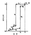
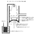
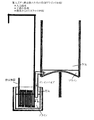
氷晶が小滴内にどのように形成されるかを決定するために、廃水を凍らせる研究が行われた。ワ ガオ(Wa Gao)博士による研究で「選択された産業廃棄物の処理代案としてのスプレーすることによる部分冷却」と題する彼女の論文で議論される。廃水の単一の小滴に対する凍結温度の影響が研究された。単一の小滴(約マイナス5℃の真水の凍結温度以下)は、チルド空気垂直風胴の中で、零度以下の空気温度(つまりマイナス5.5℃からマイナス17.7℃の間)の上向き通風に露出された。テストは、統計情報を得るために同じ小滴サイズおよび小滴条件で繰り返し行なわれた。彼女は、各小滴の結氷が小滴の下端で始まり、次に、0.23秒で小滴の外側表面エリアを包むことを見いだした。氷シェルが厚くなるとともに、廃水の内部が凍った。完全な2,800ミクロンの小滴は、完全に平均時間7秒で凍った。すべての場合に、結氷は20秒で完了した。小滴の固体の氷部分は純水から作られた。また、そのまわりの残る液体のブラインは、濃縮廃水から成った。それが圧縮不可能な液体が搾り出されるとき、氷の中の内部応力のために内部の液体のブラインが外部へ搾り出された時に、氷球体は結氷プロセスの間にばらばらにされる。別の研究では、地面で氷粒子の大きな塚を直接生産するために、廃水は、寒い北極の冬の天候の中で戸外でスプレーされた。小滴が飛行中の間に最初の結氷は起こったが、小滴が地面に降りた後、追加の結氷および分離が生じた。一旦塚が形成されたならば、その後、春にそれを溶かすことができ、灌漑目的のために使用した。 A study was conducted to freeze the wastewater to determine how ice crystals form in the droplets. Discussed in her paper entitled “Partial Cooling by Spraying as an Alternative Treatment of Selected Industrial Waste” in a study by Dr. Wa Gao. The effect of freezing temperature on a single droplet of wastewater was studied. A single droplet (below the freezing temperature of fresh water of about minus 5 ° C) will have a subzero air temperature (ie, between minus 5.5 ° C and minus 17.7 ° C) in a chilled air vertical wind tunnel. It was exposed to upward ventilation. The test was repeated with the same droplet size and droplet conditions to obtain statistical information. She found that the freezing of each droplet began at the bottom of the droplet and then wrapped the outer surface area of the droplet in 0.23 seconds. As the ice shell thickened, the inside of the wastewater froze. Complete 2,800 micron droplets were completely frozen with an average time of 7 seconds. In all cases, freezing was completed in 20 seconds. The solid ice portion of the droplet was made from pure water. The remaining liquid brine around it consisted of concentrated wastewater. When the incompressible liquid is squeezed out, the ice spheres are broken apart during the icing process when the internal liquid brine is squeezed out due to internal stresses in the ice. In another study, wastewater was sprayed outdoors in cold Arctic winter weather to produce large mounds of ice particles directly on the ground. The first icing occurred while the droplet was in flight, but additional icing and separation occurred after the droplet landed on the ground. Once the mound was formed, it could then be melted in the spring and used for irrigation purposes.
上に議論された既存の脱塩方法およびシステムの欠点のために、新鮮な飲料水が海水から生産されることを可能にする非常に効率的でコスト効率の良い脱塩方法に対する必要がある。 Due to the shortcomings of existing desalination methods and systems discussed above, there is a need for a highly efficient and cost effective desalination method that allows fresh drinking water to be produced from seawater.
発明の要約
本発明は水脱塩システムと協力する圧縮空気エネルギーの使用に関し、風によって生産されたエネルギーまたは他のエネルギー源によりエネルギーが生成され、圧縮空気を生産するために使用でき、たとえばターボ・エキスパンダーの使用により圧縮空気が解放され膨張する場合、副生成物としてそれはチルド空気を劇的に生産でき、ついで海水の冷凍および脱塩に使用できる。すなわち、凍結結晶化方法の場合のように脱塩目的のために海水の温度を低減するために冷媒を使用するのではなく、本発明では圧縮空気エネルギーを解放し膨張させることにより得られる清潔なチルド空気を使用して、直接海水小滴と混合し、新鮮な凍結された氷粒子を生成する。
SUMMARY OF THE INVENTION The present invention relates to the use of compressed air energy in cooperation with a water desalination system, where energy is generated by energy produced by wind or other energy sources and can be used to produce compressed air, such as turbo When compressed air is released and expands through the use of an expander, as a by-product it can produce chilled air dramatically and can then be used for freezing and desalination of seawater. That is, instead of using a refrigerant to reduce the temperature of seawater for desalination purposes as in the case of the freeze crystallization method, the present invention provides a clean clean that is obtained by releasing and expanding the compressed air energy. Using chilled air, mix directly with seawater droplets to produce fresh frozen ice particles.
全体として、このアプローチは、脱塩の逆浸透方法を放棄させ、多段式のフラッシュ蒸留方法の場合でのように、大気圧での高い蒸発熱ではなく、大気圧での氷融解の低温での凍結結晶化プロセスを使用する。 Overall, this approach abandoned the desalting reverse osmosis method, as in the case of the multistage flash distillation method, rather than the high heat of vaporization at atmospheric pressure, rather than the low temperature of ice melting at atmospheric pressure. A freeze crystallization process is used.
アプローチは一般に次の工程を含む:
1. 1気圧より若干高い圧力で、マイナス175°Fの温度で、冷却空気の体積流れを生成し、絶縁された混合室へこの冷却空気を導入すること。この冷却空気は圧縮空気の膨張により得られる。この圧縮空気は、コンプレッサにより生成され、ターボ・エキスパンダーを通って直接冷却空気を生成するか、またはターボ・エキスパンダーと発電機を通り、電気と副生成物の冷却空気を生成することにより得られる。
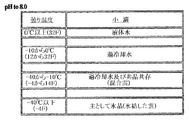
2. 海水の体積流れを生成する。これは室内へ小滴雲としてスプレーでき、冷却空気と混合され、海水小滴の温度を共晶温度(それは標準的な海水では華氏約マイナス6.2度である)またはそれよりも少し高い温度にまで低下させる。
3. 海水小滴が冷却空気と混合し、熱交換により凍結され始め、純水氷晶が生じ始め、塩気のあるブライン溶液からの分離を始める。時間とともに(つまり数秒未満で)、冷凍の氷粒子は室の底部へ落ち始める。そこでは熱交換のために空気の温度はより暖かくなり、空気および底部で氷粒子の成長している堆積物が、ちょうど好ましくは共晶温度より若干上の平衡温度に結局達する。その後、低密度の氷粒子は浮かび、底部に集まった高密度の塩気のあるブライン溶液の上面で合体し、氷/雪塊を形成し、それは塩気のあるブライン溶液の上で拡大し浮かび続ける。高密度塩ブラインは氷粒子から分離し続け、側面からまた氷/雪塊に存在する通路および孔を通って流れでる。水のスプレーを含む真水洗浄カラムは氷/雪塊からのブラインの流去を容易にし、氷塊をさらに清潔にするのを支援するために使用できる。
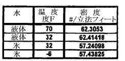
注:ブラインの密度は濃縮された時の1.35gm/ccから海水中の1.025gm/ccの間にあることができる;なお純水の密度は1 gm/ccであり;真水氷の密度は0.917 gm/ccであり;また、雪の密度は0.1 gm/cc未満である。したがって、高密度ブラインは、氷/雪塊中の孔の間から流れ出て、氷フラグメント間のすきまから外に流れる。
4. 氷/雪塊が形成された後のサイクルの最後に、氷/雪塊は好ましくは回収され、次に融解され、浄化された飲料水が生産される。塩気のあるブライン溶液は時間と共により濃く、塩分が高くなり、室から形成されるすべての塩の固体と共に回収され、プロセスは再び開始されることができる。堆積された塩および他のミネラルは、後の工業的用途のために保存できる。あるいは堆積された時適切に扱われなければならない。
The approach generally includes the following steps:
1. Generate a volumetric flow of cooling air at a pressure slightly above 1 atm and a temperature of minus 175 ° F. and introduce this cooling air into the insulated mixing chamber. This cooling air is obtained by the expansion of compressed air. This compressed air is generated by a compressor and can be obtained by generating cooling air directly through a turbo expander or by passing through a turbo expander and a generator to generate electricity and by-product cooling air.
2. Produces a volumetric flow of seawater. It can be sprayed into the room as a cloud of droplets, mixed with cooling air, and the temperature of the seawater droplets is equal to or slightly higher than the eutectic temperature (which is about minus 6.2 degrees Fahrenheit in standard seawater) To lower.
3. Seawater droplets mix with cooling air, begin to freeze by heat exchange, begin to produce pure water ice crystals, and begin separation from salty brine solutions. Over time (ie in less than a few seconds), frozen ice particles begin to fall to the bottom of the chamber. There, due to heat exchange, the temperature of the air becomes warmer, and the growing deposits of air and ice particles at the bottom eventually reach an equilibrium temperature, just preferably slightly above the eutectic temperature. The low density ice particles then float and coalesce on top of the dense salty brine solution gathered at the bottom to form an ice / snow lump that continues to expand and float on the salty brine solution. The dense salt brine continues to separate from the ice particles and flows from the sides and through the passages and holes present in the ice / snow lump. A fresh water wash column containing a spray of water can be used to facilitate the draining of the brine from the ice / snow block and to help clean the ice block further.
Note: The density of the brine can be between 1.35 gm / cc when concentrated to 1.025 gm / cc in seawater; the density of pure water is 1 gm / cc; the density of fresh water ice Is 0.917 gm / cc; and the snow density is less than 0.1 gm / cc. Thus, the high density brine flows out between the holes in the ice / snow lump and out of the gap between the ice fragments.
4). At the end of the cycle after the ice / snow mass is formed, the ice / snow mass is preferably recovered and then thawed to produce purified drinking water. The salty brine solution becomes thicker with time, gets higher in salinity and is recovered with all the salt solids formed from the chamber and the process can be started again. Deposited salts and other minerals can be stored for later industrial use. Or it must be handled properly when deposited.
本発明は、海水を冷凍し脱塩するための冷凍温度のソースとして、圧縮空気の膨張を使用することを好ましくは企図する。冷却空気を生産するために企図される少なくとも3つの異なる方法は以下のとおりである:
(1) コンプレッサおよび大きな高圧貯蔵タンクを有する圧縮空気エネルギー貯蔵システム、ここでターボ・エキスパンダーが所望の際に圧縮空気を解放し膨張するために使用され、生成されたエネルギーは冷却空気および/または電気エネルギーに変換される。
(2) 電気および冷却空気の両方を生成する能力を有するターボ・エキスパンダー、ここで発電能力は好ましくは補助的な圧縮機能力により置き換えられ、これはターボ・エキスパンダーの仕事を利用し、付随するサージタンク内に排出された圧縮空気を充満させる。
(3)エネルギーを最初に貯蔵する必要なしに、冷却空気を生産する能力を有するターボ・エキスパンダー。
それぞれの場合において、冷却空気は混合室に射出され、混合室に射出される海水から冷却を提供する。
The present invention preferably contemplates the use of compressed air expansion as a source of refrigeration temperature for freezing and desalting seawater. At least three different methods contemplated for producing cooling air are as follows:
(1) A compressed air energy storage system having a compressor and a large high pressure storage tank, where a turbo expander is used to release and expand the compressed air when desired, and the generated energy is cooled air and / or electric Converted into energy.
(2) A turbo expander with the ability to generate both electricity and cooling air, where the power generation capability is preferably replaced by an auxiliary compression function, which takes advantage of the work of the turbo expander and is associated with surge Fill the tank with compressed air.
(3) A turbo expander with the ability to produce cooling air without the need to store energy first.
In each case, the cooling air is injected into the mixing chamber and provides cooling from the seawater injected into the mixing chamber.
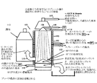
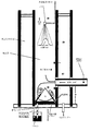
本発明は、バッチ式に、混合室内で行われることができる脱塩システムを好ましくは含む。そこでは真水で作られる多くの氷/雪の塊が形成され、次に室から回収され、融解され、純水を形成する。各々のバッチを形成するために、室内の海水および冷却空気は適切に混合されなければならない。したがって、海水は好ましくは加圧され、配列されたノズルを通り、小滴のスプレーあるいは雲を形成する。混合室の中への冷却空気を射出することにより、その結果スプレーされた海水小滴は暴露され冷却空気とともに循環され、氷晶が各小滴内に形成され始める。各海水小滴の体積サイズおよび室に供給された海水および冷却空気の温度は、好ましくは、室の全体的なサイズおよび構成と同様に注意深く先決される。さらに好ましくは、海水スプレーおよび冷却空気が室に射出され、混合される方法が予め決定され、得られた混合物が凍結および脱塩のために最適な温度に速く達することを保証する。 The present invention preferably includes a desalination system that can be carried out batchwise in a mixing chamber. There, many ice / snow chunks made of fresh water are formed and then recovered from the chamber and melted to form pure water. In order to form each batch, the room seawater and cooling air must be properly mixed. Thus, the seawater is preferably pressurized and passes through the arranged nozzles to form a spray of droplets or clouds. By injecting cooling air into the mixing chamber, the resulting sprayed seawater droplets are exposed and circulated with the cooling air, and ice crystals begin to form within each droplet. The volume size of each seawater droplet and the temperature of the seawater and cooling air supplied to the chamber are preferably carefully determined as well as the overall size and configuration of the chamber. More preferably, the manner in which seawater spray and cooling air are injected and mixed into the chamber is predetermined and ensures that the resulting mixture quickly reaches the optimum temperature for freezing and desalting.
典型的には、海水小滴に関して、凍結は外側から内側へと生じるが、時間とともに、形成される氷構造は海水の塩水を外側に押し出し、塩水を拒絶する。濃縮されたブラインコアのまわりの氷シェルが内部応力および氷シェル・フラグメントを発展させ、氷シェルの外側へ濃縮された液体ブラインを押し出す。氷晶のアグロメレーションはブラインを外側に押しだし、モノリシックな氷晶を有する全体構造を結局形成し、これはブラインで覆われることになる。これらのコーティングされた氷晶が互いに影響を与える場合、ブライン溶液は新しく形成された氷晶合成物を囲むことを強いられる。ブラインに囲まれた氷のマクロ組織が完全に分離されるまで、このプロセスは継続する。室の底に、生ずる最終の氷塊が多孔性の雪のように現われ、ブラインの重力排水を許す。議論されるように、補足の真水を、氷に付着するすべてのブラインを解放するためにさらに付加することができる。また、冷凍とより多くのブラインを解放する機能を有する真水は、再使用のために回収できる。 Typically, for seawater droplets, freezing occurs from the outside to the inside, but over time, the ice structures that are formed push the seawater brine outward and reject the saltwater. The ice shell around the concentrated brine core develops internal stress and ice shell fragments, pushing the concentrated liquid brine out of the ice shell. The agglomeration of ice crystals pushes the brine outward, eventually forming an overall structure with monolithic ice crystals, which will be covered with brine. If these coated ice crystals affect each other, the brine solution is forced to surround the newly formed ice crystal composition. The process continues until the ice macrostructure surrounded by brine is completely separated. At the bottom of the chamber, the resulting final ice mass appears like porous snow, allowing gravity drainage of the brine. As discussed, supplemental fresh water can be further added to release any brine that adheres to the ice. Also, fresh water that has the function of freezing and releasing more brine can be recovered for reuse.
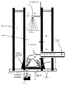
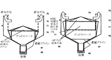
室内へ導入される海水スプレーおよび冷却空気の方向は、氷晶およびしたがって氷塊の適切な構成に寄与できる。この点で、本発明は1)向流および2)並流配置の両方を企図する。どちらの方法を使用するかを決定する要因は、海水がどれくらい直ちに冷凍される必要があるかに依存する。これは室に入る前に海水がどれくらい冷たいか、冷却空気はどれくらい冷たいか、室のサイズ、海水小滴が冷却空気にどのように露出され冷却空気と循環するか、それぞれの導入される量等に依存する。 The direction of seawater spray and cooling air introduced into the room can contribute to the proper construction of ice crystals and thus ice blocks. In this regard, the present invention contemplates both 1) countercurrent and 2) co-current arrangements. The factor that determines which method to use depends on how quickly the seawater needs to be frozen. This is how cold the seawater is before entering the room, how cold the cooling air is, the size of the room, how the seawater droplets are exposed to and circulate with the cooling air, the amount of each introduced, etc. Depends on.
向流の実施態様では、好ましくはシステムは室の下方向へ海水の小滴がスプレーされる室を有する。これはターボ・エキスパンダーからの冷却空気を落下してくる液滴に対して上方向に吹き上げることを可能とし、それにより海水液滴を循環させ凍らせ、次に、室の底に落下させることを可能とする。これは向流プロセスと呼ばれ、海水スプレーおよび冷却空気が反対方向で流れ、室内での小滴の滞留時間を増加させる。別の実施態様では、好ましくはシステムは室の下方向へ海水の小滴をスプレーする少なくとも1つのスプレーノズルを有し、ターボ・エキスパンダーからの冷却空気は落下する小滴と同じ方角の下方向へ吹き出される。これは並流プロセスと呼ばれ、海水スプレーおよび冷却空気が同じ方角に流れ、過冷却空気が最も大きな熱伝達速度で入って来る小滴に作用することを可能にする。 In the countercurrent embodiment, the system preferably has a chamber in which droplets of seawater are sprayed downwardly in the chamber. This allows the cooling air from the turbo expander to be blown upward against the falling droplets, thereby circulating and freezing the seawater droplets and then dropping them to the bottom of the chamber. Make it possible. This is called a countercurrent process, where seawater spray and cooling air flow in opposite directions, increasing the residence time of the droplets in the room. In another embodiment, preferably the system has at least one spray nozzle that sprays a drop of seawater down the chamber, and the cooling air from the turbo expander is down in the same direction as the falling drop. Blown out. This is referred to as a co-current process, allowing seawater spray and cooling air to flow in the same direction and allow the supercooled air to act on the incoming droplets with the greatest heat transfer rate.
別の態様では、氷が壁に集まらないようにし、かつ氷塊がそれに付着しないようにするために、室の壁は引き込まれた暖かい海水および/または圧縮空気からの熱で好ましくは加熱される。引き込まれた海水が室壁を通される場合、好ましく生じる熱交換は室へスプレーされる前に、あらかじめ海水を冷やすことを支援する。好ましくは、海水は結晶化室周囲を包むチューブあるいはキャビティーを通って送られ、海水が室に入る前であっても、冷凍温度の近くまで海水を予備冷却する。すなわち、室へ導入される過冷却空気は室壁を冷やす効果がある。その結果、壁の周囲をチューブまたはキャビティーで包み、チューブまたはキャビティーに海水を通すことによって、それらは熱交換器の役割を果たし、海水を予備冷却することを可能にする。この方法は、一旦海水が結晶化室に入れば、より速く冷凍され、底部に落下し、連続的に冷凍され固体化される。好ましくは、この方法は、室に入る前でさえ海水の温度は凍結点に近く、蒸留水の凝固点(0℃または32°F)よりわずかに低い。 In another aspect, the chamber walls are preferably heated with heat from the drawn warm seawater and / or compressed air so that ice does not collect on the walls and ice clumps do not adhere to it. When drawn seawater is passed through the chamber walls, the heat exchange that preferably occurs assists in precooling the seawater before it is sprayed into the chamber. Preferably, the seawater is sent through a tube or cavity surrounding the crystallization chamber and precools the seawater to near the freezing temperature, even before the seawater enters the chamber. That is, the supercooled air introduced into the chamber has an effect of cooling the chamber wall. As a result, by surrounding the walls with tubes or cavities and passing seawater through the tubes or cavities, they act as heat exchangers and allow the seawater to be precooled. In this method, once seawater enters the crystallization chamber, it is frozen more quickly, falls to the bottom, and is continuously frozen and solidified. Preferably, in this method, even before entering the chamber, the temperature of the seawater is close to the freezing point and slightly below the freezing point of distilled water (0 ° C. or 32 ° F.).
圧縮機からの廃熱も同様の効果のために使用できる。すなわち結晶化室のまわりでは、氷粒子状物質が室壁にくっつき、かつ集まるのを防ぐことは望ましい。したがって、廃熱を使用する1つの方法は、結晶化室の近くに伸びるチューブまたはキャビティー内に、廃熱によって生産された加熱された圧縮空気、あるいは温水を分配することである。この点で、好ましくは、チューブまたはキャビティーで、氷粒子状物質が蓄積する場所である室の周囲を包むことができる。圧縮機からの加熱された空気が室壁を通される場合、これが熱交換器の役割をするので、好ましくは圧縮空気は、それがターボ・エキスパンダーへ送られ、冷却空気を生産するために膨張される前にあらかじめ冷却される。したがって、ターボ・エキスパンダーによって解放される空気はさらに冷たくすることができる。 Waste heat from the compressor can also be used for similar effects. That is, it is desirable to prevent ice particulate matter from sticking to the chamber wall and collecting around the crystallization chamber. Thus, one method of using waste heat is to distribute heated compressed air produced by the waste heat, or hot water, into a tube or cavity that extends near the crystallization chamber. In this regard, preferably a tube or cavity can wrap around the chamber where the ice particulate matter accumulates. When heated air from the compressor is passed through the chamber walls, it acts as a heat exchanger, so preferably the compressed air is expanded to produce cooling air as it is sent to the turbo expander Pre-cooled before being done. Thus, the air released by the turbo expander can be further cooled.
海水がその共晶温度(華氏約マイナス6度)の近くに冷却され、固体の氷(冷凍の真水)および液体のブライン(水溶剤中の高度に濃縮された塩溶質)に分離され、氷晶の形成がその構造から海水を排除するために脱塩が起こり、さらに室の底での密度の大きな差によって引き起こされる一層の分離が生ずる。この点で、海水の凍結は好ましくは3つの段階で生じる:(1)冷蔵結晶化壁を取り囲むチューブまたはキャビティーを通してポンプ輸送されたろ過された海水の冷却(強い冷却効果)、(2)室内の冷却空気を通って飛行する間に海水の小滴を冷却する(小滴の冷却の短い滞留時間)、および(3)半−冷凍された小滴が室の底部に堆積した後に冷却し、氷塊を形成する(最長の滞留時間)。 Seawater is cooled close to its eutectic temperature (about minus 6 degrees Fahrenheit) and separated into solid ice (frozen fresh water) and liquid brine (highly concentrated salt solute in aqueous solvent) Desalination occurs because the formation of water eliminates seawater from the structure, and further separation occurs due to the large difference in density at the bottom of the chamber. In this regard, seawater freezing preferably occurs in three stages: (1) cooling of filtered seawater pumped through a tube or cavity surrounding the refrigerated crystallization wall (strong cooling effect), (2) indoors Cool the seawater droplets while flying through the cooling air (short residence time for cooling the droplets), and (3) cool after the semi-frozen droplets are deposited at the bottom of the chamber, Form ice mass (longest residence time).
冷却空気を通る小滴の下方への飛行中に、小滴はその中心の方へ向けて次第に内側へ冷え始める。また、結局、氷晶は小滴のシェル内に形成され始める。1例において、直径で4,000ミクロンよりも大きな小滴は、まだ凍結されない内部のコア部分を持つことがあり、直径200ミクロン未満である小滴は、その中心まで完全に凍結されることがある。 During the downward flight of droplets through the cooling air, the droplets begin to cool gradually inward toward its center. Eventually, ice crystals begin to form within the shell of the droplet. In one example, a droplet larger than 4,000 microns in diameter may have an inner core portion that is not yet frozen, and a droplet that is less than 200 microns in diameter may be completely frozen to its center. is there.
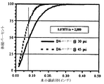
小滴がすべて同じサイズでも、いくらかは遅く凍結し、いくらかは早く凍結する。これはサイズの同じそれぞれの小滴においてどのようにして、数とサイズが異なる微視的な核のまわりに氷が形成されるかというプロセスのためである。直径が8,000ミクロン以上の小滴は向かい風の中で粉々になり、小さな小滴へ分割する傾向があることに留意すべきである。したがって、大きな小滴(直径で4,000ミクロン以上として定義される)のまわりの氷層は、液体の核のまわりの氷層の厚さが成長している間にばらばらになる。マイナス17℃の冷却空気、プラス5℃での冷却海水小滴、および直径が4,200、3,400および2,800ミクロンの豚舎廃水小滴を使用した実験で、pH=7.1(中性)では平均7秒で完全に小滴がほぼ凍結し、pH=11(アルカリの限界pH=14である)では平均7.5秒で完全に小滴がほぼ凍結した。ここで飛行の滞留時間は約2.5秒であった。したがって、凍結の多くが、結晶化室の底への小滴の沈積の後に生じ得る。小滴の表面のシェルは非常により少ない時間、すなわち0.23秒で凍った。 Even if the droplets are all the same size, some will freeze more slowly and some will freeze more quickly. This is due to the process of how ice is formed around microscopic nuclei of different numbers and sizes in each droplet of the same size. It should be noted that droplets with a diameter of 8,000 microns or more tend to shatter in the headwind and break up into small droplets. Thus, the ice layer around a large droplet (defined as 4,000 microns or more in diameter) breaks apart while the thickness of the ice layer around the liquid core is growing. In experiments using minus 17 ° C. cooling air, plus 5 ° C. cooling seawater droplets, and piglet wastewater droplets with diameters of 4,200, 3,400 and 2,800 microns, pH = 7.1 (medium In the case of (sex), the droplets were almost completely frozen in an average of 7 seconds, and in the case of pH = 11 (alkaline limit pH = 14), the droplets were completely frozen in an average of 7.5 seconds. Here, the flight residence time was about 2.5 seconds. Thus, much freezing can occur after the deposition of droplets at the bottom of the crystallization chamber. The shell on the surface of the droplets frozen in much less time, ie 0.23 seconds.
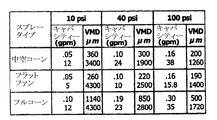
凍結して、固体の氷粒子状物質および液体のブラインの二相の溶液を形成することは小滴にとって重要である。したがって、飛行する間に、共晶温度あるいはその共晶温度の近くまで小滴が達することは望ましい。他方では、小滴が室を通って落下する際に小滴が冷たく(共晶温度より冷たい)なりすぎる場合、各小滴内の真水は固体の塩の結晶および固体のブラインと一緒に凍結できる。その場合には、真水から塩を分離することは可能ではないことがある。例えば、海水スプレーが様々な小滴サイズから成る場合に、これは起こることがある。より小さな小滴は共晶温度以下に達することがあり、それらが室の底に達する時までに完全に凍ることがある。この点で、平均直径が4,000ミクロン近くの雲を分散させるように設計されたスプレーノズルは、より小さな塊部分も生成するが、大部分の小滴は直径400ミクロンの範囲内である。これらのより小さな粒子状物質は10倍小さな沈降速度を有し、10倍長い滞留時間を有する。更に、並流構成中のノズルを出る華氏マイナス135度あるいは華氏マイナス175度の局所的な空気流れと相互作用するときに、これらの小さな粒子は早く凍結し、共晶温度より下の温度に達する。
It is important for the droplets to freeze to form a two-phase solution of solid ice particulate and liquid brine. Therefore, it is desirable for the droplets to reach the eutectic temperature or close to that eutectic temperature during flight. On the other hand, if the droplets become too cold (falling below the eutectic temperature) as they drop through the chamber, the fresh water in each droplet can be frozen together with solid salt crystals and solid brine. . In that case, it may not be possible to separate the salt from fresh water. This can occur, for example, when the seawater spray consists of various droplet sizes. Smaller droplets can reach below the eutectic temperature and freeze completely by the time they reach the bottom of the chamber. In this regard, spray nozzles designed to disperse clouds with an average diameter close to 4,000 microns also produce smaller chunks, but most droplets are in the range of 400 microns in diameter. These smaller particulates have a
したがって、この非常に冷たい温度領域を下方向に飛行する小さな液滴は、確かに、(1)真水の固体の氷、(2)付随する水分子と共に2つの水分子に結合するそれぞれの塩分子との固体の塩および(3)固体の塩の結晶、から造られる1つの固形微粒子への小滴の不適当な結晶化を引き起こす。冷たい空気中の小さな粒子の飛行中に、真水からのブラインの分離はない。しかしながら、議論されるように、室の底で大きな小滴から形成される氷粒子塊上に小滴が堆積したときに分離が生じ、これは好ましくは共晶温度より暖かい平衡温度を有する。 Thus, the small droplets flying down this very cold temperature region do indeed (1) fresh solid ice, (2) each salt molecule bound to two water molecules with accompanying water molecules. Inadequate crystallization of the droplets into one solid particulate made from (3) solid salt crystals and (3) solid salt crystals. There is no separation of brine from fresh water during the flight of small particles in cold air. However, as will be discussed, separation occurs when droplets accumulate on an ice particle mass formed from large droplets at the bottom of the chamber, which preferably has an equilibrium temperature warmer than the eutectic temperature.
直径で数百ミクロンのオーダーの非常に小さな粒子は、スプレーノズルに近い領域で、共晶温度よりはるかに冷たい気温にさらされた時、それらの中心まで完全に凍結することがある。これらの小さな小滴が、結晶化室の底のより暖かい氷/雪塊上に堆積した場合、それらは共晶点よりわずかに暖かい平衡温度に好ましくは暖められる。したがって、小さな小滴が共晶温度以下に凍結される場合、それらは共晶温度以上に戻して溶かすことができる。そのポイントでは、固体の多孔性の雪/氷構造と液体の食塩水(ブライン)との通常の分離が生じる。たとえ典型的なより大きな直径粒子状物質をスプレーしても、ある範囲内の粒径の分配を含む、より小さな粒子状物質が常に存在する。より小さな粒子状物質は数において大きいが、全体として非常に大きな量として寄与しない。 Very small particles on the order of a few hundred microns in diameter may freeze completely to their centers when exposed to temperatures much cooler than the eutectic temperature in the region near the spray nozzle. If these small droplets are deposited on the warmer ice / snow lump at the bottom of the crystallization chamber, they are preferably warmed to an equilibrium temperature slightly warmer than the eutectic point. Thus, when small droplets are frozen below the eutectic temperature, they can be melted back above the eutectic temperature. At that point, a normal separation of the solid porous snow / ice structure and the liquid brine (brine) occurs. Even if a typical larger diameter particulate material is sprayed, there will always be smaller particulate material, including a distribution of particle sizes within a certain range. Smaller particulates are large in number but do not contribute as a very large amount as a whole.
この点で、室の底部の氷塊が共晶温度より若干高い(より暖かい)温度に維持され、それぞれの氷粒子を取り囲むすべての残留する塩ブラインが、氷の内部にトラップされ凍結されるのでなく、それらが排出され、氷塊の側面を流れ落ち、または氷/雪塊の中に形成されたボイドまたは通路を通って排出されることは望ましい。従って、室の内部の冷却空気の温度をコントロールすること、並びに氷塊が室から取り除かれる前に、塩ブラインが流れ出るための十分な時間を許容することは、最適の結果を得るために重要である。ある場合には、ブラインが流れ出るための十分な時間が無かったために、サイクルの最後の数秒の間にいくつかの小滴が堆積することがある。これは、最終飲料水中の非常に小さな量の不純物に寄与する、小さなフラクションである。 In this regard, the ice mass at the bottom of the chamber is maintained at a temperature slightly higher (warm) than the eutectic temperature, and all remaining salt brine surrounding each ice particle is not trapped and frozen inside the ice. It is desirable that they be discharged, run down the sides of the ice mass, or through voids or passages formed in the ice / snow mass. Therefore, it is important to control the temperature of the cooling air inside the chamber and to allow sufficient time for the salt brine to flow out before the ice block is removed from the chamber. . In some cases, several droplets may accumulate during the last few seconds of the cycle because there was not enough time for the brine to flow out. This is a small fraction that contributes to a very small amount of impurities in the final drinking water.
海水の凍結は、浮力のある純水氷粒子状物質の形成を可能とし、付随する塩気のあるブラインは微量であり、室の底に塩および他の不純物を塩気のあるブラインの中に残すことが目的である。脱塩システムは好ましくは、塩気のあるブライン(それは氷粒子状物質より濃い)から氷粒子状物質を取り除き、重力が氷粒子状物質からブラインを分離し、かつ少なくとも2つの方法のうちの1つで、氷粒子状物質を清潔にするのを支援できるようにする。 Freezing of seawater allows the formation of buoyant pure water ice particulates, with traces of accompanying salty brine leaving salt and other impurities in the salty brine at the bottom of the chamber. Is the purpose. The desalination system preferably removes ice particulates from salty brine (which is thicker than ice particulates), gravity separates the brine from the ice particulates, and one of at least two methods. So that you can help clean the ice particulate matter.
最初に、氷粒子状物質は、それらが互いの上に落ちて氷粒子状物質が室の底に蓄積することを可能にすることにより、氷/雪塊を形成する。時間とともに、氷粒子状物質が落ちて、それらが互いに付着し、それらは集団的に氷塊を形成する。液体のブラインが固体の氷より濃いので、それは塩気のあるブラインの上に浮かぶ傾向がある。この点で、室の中心へ海水小滴を導入することにより、氷粒子状物質が円錐形の氷塊を形成するようにシステムは適合される。ここでこのように形成された氷粒子は室の中心にも蓄積する。海水スプレーは、好ましくは室のセンターラインに向けられ、その結果、氷粒子状物質は壁に集まらないようにされ、室の底に形式された氷塊は室の中心に生ずる傾向があり、つまり逆円錐型の形になる傾向がある。一方では、この利点は、それぞれの純水氷粒子をカプセルに入れるかまたはそれに付着する塩気のあるブラインが側面を流れ落ちることを可能とし、氷塊中にトラップされない。すなわちそれが固体化するときに、塊に生ずることがあるポケットあるいは割れ目の中にトラップされない。円錐形の氷塊の形成によって、各氷粒子に付着するブラインはトラップされずに側面を流れ落ちる。その結果、塩気のあるブラインは、有効に求められる氷塊から分離できる。他方では、研究は、氷塊は全体にわたって流路およびボイドを形成するかも知れず、すべての蓄積された塩ブラインはトラップされずに、流路またはボイドを介して塊から排出される場合がある。氷塊はこの点で雪のように見えて、ブラインが通り過ぎることを可能にするような多孔性である。 Initially, the ice particulates form an ice / snow lump by allowing them to fall on top of each other and allow the ice particulates to accumulate at the bottom of the chamber. Over time, the ice particles fall and they adhere to each other, and they collectively form an ice mass. Since liquid brine is thicker than solid ice, it tends to float on salty brine. In this regard, the system is adapted so that the ice particulates form a conical ice mass by introducing seawater droplets into the center of the chamber. The ice particles thus formed also accumulate in the center of the chamber. The seawater spray is preferably directed to the center line of the chamber so that ice particulates are not collected on the walls and ice blocks formed at the bottom of the chamber tend to occur in the center of the chamber, i.e. Tends to be conical. On the one hand, this advantage allows the salty brine that encapsulates or adheres each pure water ice particle to the sides and is not trapped in the ice mass. That is, when it solidifies, it is not trapped in pockets or cracks that can form in the mass. Due to the formation of conical ice blocks, the brine adhering to each ice particle flows down the side without being trapped. As a result, salty brine can be separated from effectively sought ice blocks. On the other hand, research has shown that ice blocks may form channels and voids throughout, and all accumulated salt brine may be evacuated from the blocks through channels or voids without being trapped. The ice mass looks like snow at this point and is so porous that it allows the brine to pass through.
飛行中の氷形成に加えて、特に非常に冷たい温度で、結晶化室の底に多孔性の塊を作成する別のメカニズムがある。室の底に硬い球状の小滴が集まる理想的な場合を考慮する。最も濃密に充填される構成では、最も高い密度は、それを囲む空気の3乗と比較された球体の体積の比率、あるいは[4/3*pi*r3]/[8 r3]あるいは0.52 gm/ccである。この理想値と雪の密度(0.10 gm/cc)の間に真の密度があることが期待される。これは、液体のブラインが集められた塊の底部への開いた通過を見つけるために十分な孔隙率を提供する。一旦濃厚な液体のブラインが流動を始めれば、氷粒子状物質はさらに離れて浮き、またブラインはより速く排水される。 In addition to ice formation in flight, there is another mechanism that creates a porous mass at the bottom of the crystallization chamber, especially at very cold temperatures. Consider the ideal case where hard spherical droplets collect at the bottom of the chamber. In the most densely packed configuration, the highest density is the ratio of the volume of the sphere compared to the cube of the air surrounding it, or [4/3 * pi * r 3 ] / [8 r 3 ] or 0 0.52 gm / cc. It is expected that there is a true density between this ideal value and the density of snow (0.10 gm / cc). This provides sufficient porosity to find an open passage to the bottom of the mass where liquid brine is collected. Once the concentrated liquid brine begins to flow, the ice particulates float further away and the brine drains faster.
実施態様では、真水で氷塊をすすぐ手段を有することが好ましい。真水は氷/雪の蓄積された冷凍塊上へ凍結し、およびますます多くの小滴が堆積されるとともに付着したブライン層を解放する。各氷粒子の表面に付いているブラインの一層の除去については、層の上の塩気のあるブラインの1層ごとの重力排水を支援するために室の底に置かれた氷/ブラインの層の上に好ましくは真水の射出装置がある。真水は各層に付着するときに、さらに氷粒子状物質間の隙間からの非常に薄い粘着性の塩気のあるブライン層を置き換え、この真水は凍る。氷粒子の上で凍結された真水は、補足真水の使用なしで再使用のために溶かされ好ましくは回収される。さらに高純度水が必要な場合、下流の洗浄カラムを加えることができる。この点で、華氏60度のような室温の補足の真水は、塊が形成されるときに氷塊から塩気のあるブラインを取り除くのを支援するために氷塊の上にスプレーできる。大多数の塩気のあるブラインは重力フローによって氷粒子状物質間のスペースから置き換えられる。塩気のあるブラインは、排水管を通って、室の底から好ましくは排水される。 In an embodiment, it is preferable to have means for rinsing ice blocks with fresh water. Fresh water freezes onto the ice / snow accumulated frozen mass, and more and more droplets are deposited and release the attached brine layer. For the removal of one layer of brine on the surface of each ice particle, an ice / brine layer placed at the bottom of the chamber to support gravity drainage of the salty brine layer above the layer. Above is preferably a fresh water injection device. As fresh water adheres to each layer, it also replaces a very thin, sticky, brined brine layer from the interstices between the ice particles, which freezes. Fresh water frozen on ice particles is melted and preferably recovered for reuse without the use of supplemental fresh water. If more pure water is needed, a downstream wash column can be added. In this regard, room temperature supplemental fresh water, such as 60 degrees Fahrenheit, can be sprayed onto the ice block to help remove salty brine from the ice block as the block forms. The majority of salty brine is displaced from the space between the ice particles by gravity flow. Salty brine is preferably drained from the bottom of the chamber through a drain.
室の底セクションは好ましくは穿孔されたバスケットを含む。それは落ちてくる氷粒子状物質を受け取ることができ、氷塊をその上に形成することができるが、冷却空気が室から循環することを許容する。この点で、室の側壁は好ましくは出口ポートを有し、これを通って過剰の冷却空気が室から流れでることができる。その後、空調装置に冷却空気が供給でき、冷却空気として使用できる。さらに穿孔されたバスケット以外の氷/雪塊を回収するための他の手段、たとえばピストンおよびピンサーも使用可能である。バスケットの底部に形成される氷粒子状物質は好ましくは大きな氷塊、またはいくつかの場合にはスラリーを形成し、バスケット中の穿孔は塩気のあるブラインの通過を許可し、バスケット中に純水氷粒子状物質を残す。その後、バスケットの回収によって、純水氷塊および/またはスラリーを室から回収することができる。 The bottom section of the chamber preferably includes a perforated basket. It can receive falling ice particulates and can form ice blocks on it, but allows cooling air to circulate from the chamber. In this regard, the chamber sidewall preferably has an outlet port through which excess cooling air can flow out of the chamber. Thereafter, cooling air can be supplied to the air conditioner and used as cooling air. In addition, other means for collecting ice / snow blocks other than the perforated basket may be used, such as pistons and pincers. The ice particulate matter that forms at the bottom of the basket preferably forms a large ice mass, or in some cases a slurry, and the perforations in the basket allow salty brine to pass through, with pure water ice in the basket. Leave particulate matter. Thereafter, by collecting the basket, the pure water ice block and / or slurry can be recovered from the chamber.
その後、回収される氷粒子状物質の塊は溶かされ、ホールディングタンクの底に真水を生産することができる。比較的暖かい温度の真水、この場合には華氏プラス60度、は洗浄カラムと同様、氷をすすぎ、かつ氷を溶かすために氷粒子状物質上に下へ向けてスプレーできる。別法として、洗浄水と共に、局所的な暖かい空気がホールディングタンクへ運ばれ、氷粒子状物質を溶かすのをさらに支援することができる。氷が溶けるとともに、真水小滴はバスケット中の穿孔を通り抜けて、ホールディングタンクの底に冷蔵の新鮮な飲料水の形で集められる。1つより多いバスケットが使用でき、室から各バスケットを取り除く間に脱塩および融解プロセスが中断されないようにできる。氷塊がコンベヤ上に落ちることを可能にする、たとえばドロッブダウンドアのような氷塊を回収し溶融する他の手段を設けることができ、より容易にそれを溶かすことができる場所に氷塊を移動できる。 Thereafter, the lump of recovered ice particulate matter is melted and fresh water can be produced at the bottom of the holding tank. Fresh water at a relatively warm temperature, in this case plus 60 degrees Fahrenheit, can be rinsed down and sprayed down onto the ice particles to melt the ice, similar to a wash column. Alternatively, along with the wash water, local warm air can be carried to the holding tank to further assist in melting the ice particulate matter. As the ice melts, fresh water droplets pass through perforations in the basket and are collected in the form of refrigerated fresh drinking water at the bottom of the holding tank. More than one basket can be used so that the desalting and melting process is not interrupted while each basket is removed from the chamber. Allow the ice mass to fall on the conveyor, there can be other means to collect and melt the ice mass, such as a droop down door, and move the ice mass to a place where it can be melted more easily .
氷塊が氷で作られており、したがって冷たいので、溶けた場合、生産される真水は冷たい冷蔵水になる。そこから、新鮮な冷蔵の水は飲料目的のために分配するか、あるいは空調装置によって後の使用のために貯蔵されるか、スプレーとして洗浄カラムに使用されるために結晶化室へ再度循環するかまたはホールディングタンク中のスプレーのような他の目的に使用できる。 Since ice blocks are made of ice and are therefore cold, when melted, the fresh water produced becomes cold refrigerated water. From there, fresh refrigerated water is dispensed for beverage purposes, or stored for later use by an air conditioner, or recirculated to the crystallization chamber for use in the wash column as a spray. Can be used for other purposes such as spraying in or holding tanks.
発明の詳細な説明
上に議論された水を脱塩する凍結結晶化方法は、海水中の不純物から純水を分離するために必要な海水を凍らせることを冷却装置に要求する。本発明は、副生成物として共−生成された冷却空気を生成する手段として圧縮空気エネルギー技術の使用を組込み、ターボ・エキスパンダーが脱塩目的のための好適な量の冷却空気を生産するために、圧縮空気を解放し膨張するために使用できる。
A. 圧縮空気エネルギー・システム:
本発明は、以下の3つの異なる冷却空気を製造する方法の少なくとも1つを使用することを企図する:(1)圧縮機および大きな高圧貯蔵タンクを有する圧縮空気エネルギー貯蔵システム、ここで必要な場合に圧縮空気エネルギーを解放し膨張するために、ターボ・エキスパンダーが使用され、エネルギーは冷却空気および/または電気的なエネルギーに変換できる、
(2) 電気と冷却空気を生成する2つの機能を有するターボ・エキスパンダー、
ここで、電気を生成する能力は、付随するサージタンク中に放出された圧縮空気を補充するターボ・エキスパンダーの仕事を使用する補足の圧縮機能力により好ましく置き換えられる、および
(3) エネルギーを最初に貯蔵する必要なしに、冷却空気を生産する能力を有するターボ・エキスパンダー。
これらのシステムの各々は今議論される。
1. 圧縮空気エネルギー貯蔵タンク・システム:
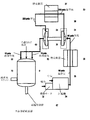
この実施態様は、図1に示されたように、好ましくは、電動モータ3、主要な圧縮機7、貯蔵タンク5、調節弁9、ターボ・エキスパンダー11および電気を起こすためのターボ発電機13を有する、圧縮空気エネルギー貯蔵システム1を含む。図1では、「A」は、それによってエネルギー源2から電気機3に電気的なエネルギーが送信されるルートを示す。エネルギー源は、風力タービン4、ウインド・ファーム、ディーゼルエンジン、発電機、または地熱発電プラント、原子力発電所、化石燃料パワー・プラントあるいは電力グリッドのような任意の公知のエネルギー源であることができる。これらの動力源のうちのいくつかは、しばしば電力需要より多い電力を生成する。過剰電力は、圧縮空気の形をして貯蔵されるだろう。電力需要を満たすために圧縮空気から電力が回収される時、共−生成された非常に冷却された空気は脱塩に使用されるだろう。モーター3は好ましくは主要な圧縮機7を運転し、空気を圧縮し、その後、貯蔵タンク5に貯蔵される。
DETAILED DESCRIPTION OF THE INVENTION The freeze crystallization method for desalting water discussed above requires the cooling device to freeze the seawater necessary to separate pure water from impurities in the seawater. The present invention incorporates the use of compressed air energy technology as a means to produce co-generated cooling air as a by-product so that the turbo expander produces a suitable amount of cooling air for desalination purposes. Can be used to release and expand compressed air.
A. Compressed air energy system:
The present invention contemplates the use of at least one of the following three different methods of producing cooling air: (1) a compressed air energy storage system having a compressor and a large high pressure storage tank, where required A turbo expander is used to release and expand the compressed air energy, which can be converted into cooling air and / or electrical energy,
(2) A turbo expander having two functions of generating electricity and cooling air;
Here, the ability to generate electricity is preferably replaced by supplemental compression capability using turbo expander work to replenish the compressed air released into the associated surge tank, and (3) energy first A turbo expander with the ability to produce cooling air without the need to store.
Each of these systems is now discussed.
1. Compressed air energy storage tank system:
This embodiment preferably comprises an
エネルギーが必要になるまで、圧縮空気エネルギーは、長期間にわたりタンク5に好ましくは蓄えることができる。その後、適切な時に、調節弁9は圧縮空気を解放するために使用でき、それがターボ・エキスパンダー11によって膨張できるようにする。このポイントでは、所望の場合、および特に電気的なエネルギーが必要な場合、主要な圧縮機7によって生成された廃熱はターボ・エキスパンダー11に循環でき、非常に冷たい温度の影響を弱め相殺する。しかしながら、冷却空気が所望の場合、脱塩が所望の場合は常にそうであるように、熱が冷却空気の温度を単に増加させるので、どんな廃熱も使用しないことは有益である。同時に、正確な温度が所望の場合、廃熱は冷却空気の温度を規制するために使用できる。
Until energy is needed, compressed air energy can preferably be stored in the
このシステム1によって生産できる出力のうちの1つは電気の形態であり、それは圧縮空気がターボ・エキスパンダー11によってタンク5から解放され高速度気流を作成する時に、ターボ発電機13によって直接起こすことができる。生産される別の出力は、冷却空気の形をしている。それはタンク5からターボ・エキスパンダー11により圧縮空気が解放され膨張するときに副生成物として共−生成される。いずれの場合も、本発明のシステム1は、これらの出力が同時に生成されるように好ましくは適応される。つまり、システムの必要によって指示されるように、圧縮空気は1)ターボ発電機13を使用して電気を、2)ターボ・エキスパンダー11を使用して冷却空気を、あるいは3)電気および冷却空気の両方を生成することができる。
One of the outputs that can be produced by this
高圧の貯蔵タンク5は好ましくは、主要な圧縮機7によって生成される高圧に耐えるように設計され提供される。またタンク内の一貫した温度を維持するように絶縁される。
タンク5は、さらにパイプラインあるいは加圧空気を保持するための他のコンテナの形をとることができる。用語「タンク」はパイプおよび他の圧縮空気貯蔵メディアを含めるように使用される。タンク5も、好ましくは圧縮機7およびターボ・エキスパンダー11に近接して位置し、著しい圧力損失なしで、タンク5に圧縮空気を運ぶことができ、次にターボ・エキスパンダー11に循環できるようにする。
The high
The
本発明は様々なサイズのタンクが使用できるように企図されているが、本発明のシステムは好ましくは、必要に応じ貯蔵のために十分な量の圧縮空気エネルギーを提供するように、タンクのサイズはシステムの必要性、施設のサイズあるいは要求、システムのコストなどに基づくべきである。タンクの不十分な余地しかない場合、あるいは特定の適用が考慮される場合、サージタンクあるいはタンクのないバージョンが使用できる。本発明は、空気を解放し、圧縮空気を電気的なエネルギーおよび/または冷却空気に変換する任意の公知の手段を使用することを企図している。好ましい実施態様では、1つ以上のターボ・エキスパンダー11が、圧縮空気を解放し、かつ電気的なエネルギーを生成するターボ発電機13に動力を供給するために使用できる高速度気流を作成するために使用される。その後、この電気はエネルギー源によって直接供給される電気的なエネルギーを補足するために使用できる。求めに応じ、あるいは補足の圧縮機を運転するために、それは、再利用でき、タンク5に貯蔵できる補足圧縮空気を生産できる。これらの実施態様では、ターボ・エキスパンダー11は、好ましくは交流発電機にエネルギーを与える。それはAC−DCコンバータに接続され、DC−ACインバータに接続され、ついでユーザ回路にインピーダンスを一致させるために電力調整器に接続される。装置のこの連鎖は、要求された一定の周波数出力に帰着する可変周波数入力を保証する。
Although the present invention contemplates that tanks of various sizes can be used, the system of the present invention preferably provides tank sizes to provide a sufficient amount of compressed air energy for storage as needed. Should be based on system needs, facility size or requirements, system costs, etc. If there is insufficient room for the tank, or if a specific application is considered, a surge tank or a tankless version can be used. The present invention contemplates using any known means for releasing air and converting compressed air to electrical energy and / or cooling air. In a preferred embodiment, one or
任意に、脱塩が必要でない場合、圧縮空気エネルギー・システム1に熱を供給するための1つ以上の手段が、ターボ発電機13による電気の生成を促進するために提供できる。本発明は、少なくとも3つの異なるタイプの加熱システムが熱を提供するために使用できることを企図する;1)太陽からのエネルギーを利用する太陽熱コレクター、2)圧縮機によって生成された廃熱を循環させる廃熱コレクター、および3)化石燃料バーナのような別個の加熱ユニット。このシステムでは、冷却あるいは脱塩目的のための副産物として冷却空気を生成することが通常望ましいので、廃熱および他の加熱システムは、電気がターボ発電機13によって起こされている場合、または冷却あるいは脱塩目的のために冷却空気がほとんどもしくは全く必要のない場合にのみ一般に利用される。
Optionally, if desalting is not required, one or more means for supplying heat to the compressed
本発明は、たとえば水脱塩およびエアコンディショニングのような追加の二次的な目的のためにターボ・エキスパンダー11によって生成されている冷却空気を好ましくは利用するという利点を有する。それは、システムの効率を増加させる。たとえば、エアコンディショナーのために直接冷却する目的のために冷却空気を使用することに加え、および/または圧縮機へのパイプを再び通して圧縮機を冷たく保持することに加え、好ましい実施態様では冷却空気は脱塩システムを冷却するために使用される。脱塩装置からの出口冷却空気も空調装置および同種のものに使用できる。
The present invention has the advantage of preferably utilizing the cooling air generated by the
論理回路6は、好ましくは貯蔵タンク5、圧縮機7、ターボ・エキスパンダー11、ターボ発電機13、加熱ユニット、冷凍コンポーネントなどの操作をコントロールするために制御系を含む。制御系の1つの本質的機能は、顧客に電力を直ちに向けること、および所望の場合には圧縮機をバイパスすることである。そのような場合、顧客が使用することができない動力源から利用可能な過剰電力がある場合に限り、電力は圧縮機へ送られる。他方では、発電所から利用可能な電力がないが、顧客が電力を必要とする場合には、圧縮空気は必要な電力不足分を供給するために解放できる。電力不足があり、貯蔵タンクは最低必要電力未満である状況では、予備電力を作動することが必要なことがある。制御系は、タンクからのまたはタンクへの圧縮空気のフローの規制により、タンク5中の圧縮空気エネルギーのレベルを維持することができるように好ましくは設計される。制御系は、システムを自動的に実行できるようにあらかじめプログラムされるマイクロプロセッサを好ましくは持っている。
The
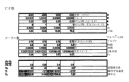
典型的な500キロワットのターボ・エキスパンダー11あるいは他の公知のエキスパンダーが、圧縮機7によって生産された圧縮空気を貯蔵する貯蔵タンク5に連絡して使用できる。タンク5中の圧縮空気の膨張によって行なわれた仕事に関連した排気空気は、非常に冷たい空気を生成できる。その後、それは脱塩目的に使用される。この例において、ターボ・エキスパンダー11は、好ましくは圧縮空気の入力を華氏70度で約200−psia(入力エントロピー=1.4552 BTU/#− °R)で、出力圧力を14.67−psiaとすることができ、これは等エントロピーに約華氏マイナス210度まで膨張することができる(出力エントロピー=1.4552 BTU/#− °R)。膨張の熱力学的効率が、ターボエキスパンダーを横切る過度に大きな圧力損失のためにわずか79%ならば、排出温度は約華氏マイナス152.7度になるであろう。
A typical 500
同様に、圧力200−psiaおよび華氏70度(入力エントロピー=1.4552 BTU/#− °R)の圧縮空気入力は、500キロワットのターボ・エキスパンダーでは、30psiaのより高圧力の出力を備えた等エントロピーに、華氏マイナスの153.2度(出力エントロピー=1.4552 BTU/#− °R)まで膨張する。より小さな圧力比での膨張の熱力学的効率が85%ならば、排出温度は華氏約マイナス120.6度になる。 Similarly, a compressed air input with a pressure of 200-psia and 70 degrees Fahrenheit (input entropy = 1.4552 BTU / #-° R) has a higher pressure output of 30 psia for a 500 kilowatt turbo expander, etc. Entropy expands to 153.2 degrees Fahrenheit minus (output entropy = 1.4552 BTU / #-° R). If the thermodynamic efficiency of expansion at a smaller pressure ratio is 85%, the exhaust temperature will be about minus 120.6 degrees Fahrenheit.
いずれの場合も、貯蔵タンクの熱力学および空気温度に対するその影響学が考察された。貯蔵タンク内の空気圧力は、貯蔵タンクから空気が取り出されると共に落ちる。ターボ・エキスパンダーの効率的な作業のために入力として受理可能でない温度レベルに、貯蔵タンク内の空気温度がほぼ断熱的に落ちると予想されるだろう。しかしながら、貯蔵タンクは、高い気圧を適合するために必要とされるその厚い鋼壁のために、熱の貯蔵器としても作用する。鋼タンク壁は十分な熱を保持し、華氏70度の初期温度でさえ、タンク内の残余の気温が著しく落ちないようにする。したがって、タンク内の空気温度が落ち始めるとともに、タンク壁内の顕熱は、鋼壁と内部の空気の間の負温度勾配の方向に流れ始める。最終結果は、タンク内の残余の空気がターボ・エキスパンダーによって受理可能な適度な温度降下だけを示すということである。 In both cases, the thermodynamics of the storage tank and its influence on air temperature were considered. The air pressure in the storage tank drops as air is removed from the storage tank. It would be expected that the air temperature in the storage tank would drop almost adiabatically to a temperature level that would not be acceptable as input for efficient operation of the turbo expander. However, the storage tank also acts as a heat reservoir because of its thick steel walls that are required to accommodate high atmospheric pressure. The steel tank wall retains sufficient heat so that the residual temperature in the tank does not drop significantly, even at an initial temperature of 70 degrees Fahrenheit. Therefore, as the air temperature in the tank begins to drop, the sensible heat in the tank wall begins to flow in the direction of the negative temperature gradient between the steel wall and the internal air. The net result is that the residual air in the tank shows only a moderate temperature drop that can be accepted by the turbo expander.
510kW(熱)の熱力学的力は、発電機による変換中に、2%のギヤー摩擦損失および10%のエネルギー損のために450kW(電気)を生産する。500kWのターボ・エキスパンダーの熱力学は図5の中に示される。 A thermodynamic force of 510 kW (thermal) produces 450 kW (electric) due to 2% gear friction loss and 10% energy loss during generator conversion. The thermodynamics of a 500 kW turbo expander is shown in FIG.
いずれの場合でも、ターボ・エキスパンダー11からの排気空気が脱塩目的にふさわしい非常な低温を示すことは理解される。以下に議論される共晶凍結結晶化(EFC)方法の修正された形式を使用する場合、非常に高い冷却/凍結ポテンシャルを有するそのような低温は海水真水化に非常に有用である。
In any case, it is understood that the exhaust air from the
2. サージタンク圧縮空気エネルギー・システム:
別の圧縮空気エネルギー・システムは図2の中に示される。図2は、大きな貯蔵タンクではなく、小さなサージタンク19だけがある実施態様の圧縮機15とターボのエキスパンダー17の詳細を示す。このシステムでは、ソースからのエネルギーは圧縮機15を運転するために使用でき、そこでは圧縮空気はサージタンク19へ流され、調節弁21が圧縮空気がターボ・エキスパンダー17に解放される程度をコントロールするために提供される。好ましくは、図2で見ることができるように、ターボ・エキスパンダー17からの加圧され膨張した出力空気は、2つの異なる方法で導かれる。最初に、ターボ・エキスパンダー17からの共−生産された冷却空気は、パイプ20を通って導かれ、次に以下に記載されるように、脱塩システム、あるいは他の冷却機能に配達されることができる。次に、ターボ・エキスパンダー17からの補足エネルギーはギアボックス16にシャフト18を介して循環して戻すことができる。これは次に多段階レシプロ式圧縮機23が付加的な圧縮空気エネルギーを生産することを可能にし、それはサージタンク19に戻して循環でき、放出された圧縮空気をそこに補充する。この方法で、ターボ・エキスパンダー17によって生産された、冷却空気の形では使用されない余剰のエネルギーは、より多くの圧縮空気を生産するために戻して循環することができ、これはついでより多くの冷却空気および/または電気を生産するために使用できる。
2. Surge tank compressed air energy system:
Another compressed air energy system is shown in FIG. FIG. 2 shows details of the
局所的な大気空気は、サージタンク19中の貯蔵された空気の背圧に一致する流量でレシプロ式圧縮機23によって好ましくは圧縮される。したがって、好ましくは最初の圧縮機15からの空気のポジティブな流入があり、これはターボ・エキスパンダー17に供給する空気のネガティブアウトフローと一致する往復式圧縮機23からの空気のポジティブ流入と結合する。このバランスが、圧縮機15、23およびターボ・エキスパンダー17のためのSCFM/HPカーブに依存する平衡圧で起こる。商用ハードウェアの特別のセットのための圧力は200−psigよりもわずかに高いことがある。
The local atmospheric air is preferably compressed by the reciprocating
このシステムで電気を共−生産することが所望の場合、電気を生産するために起電機にターボ・エキスパンダー17の回転軸18を接続でき、往復式圧縮機23から分離できるように、ギアーケース16を形成できる。このオプションでは、サージタンク19へ圧縮空気を再利用するために使用できるインペラーで駆動される往復式圧縮機23から、シャフト18が接続され、分離されることを可能にする。
If it is desired to co-produce electricity with this system, the
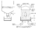
3. タンクのない圧縮空気エネルギー・システム:
図3は、貯蔵タンクの必要がない実施態様の、圧縮機31およびターボ・エキスパンダー33を含む「タンクのない」圧縮空気エネルギー・システムの詳細を示す。このシステムでは、ソースからのエネルギーは、エネルギーを最初に貯蔵する必要なしに、電動モータ32、第2の圧縮機34およびターボ圧縮機31を使用して、空気を圧縮するために使用できる。そこではターボ・エキスパンダー33を使用して、圧縮空気を解放できる。エネルギー源3によって起こされた電気により電動モータ32が直接運転できる。圧縮空気もエネルギー源3により直接生成でき、所望の場合にターボ圧縮機31を運転するようにできる。
3. Compressed air energy system without tank:
FIG. 3 shows details of a “tankless” compressed air energy system that includes a
図3で見ることができるように、電動モータ32は第2の圧縮機34を運転するために好ましくは使用される。第2の圧縮機34からの加圧された出力空気は熱交換器35により冷却され、配管36に沿って延び、圧縮機34からの空気はついでターボ圧縮機31に沿って通される。ターボ圧縮機31は、好ましくは1つの運転がさらに他方を運転するようにシャフト39をターボ・エキスパンダー33と共有し、以下に議論されるように、そこではシステムは定常状態動作に達することができる。
As can be seen in FIG. 3, the
第2の熱交換器37は、ターボ圧縮機31とターボ・エキスパンダー33の間に配管38に沿って設けられ、圧縮空気がターボ圧縮機31からターボ・エキスパンダー33へ移動するときに、それが第2の熱交換器37を通り、空気をもう一度冷やすようにする。このように、ターボ・エキスパンダー33に入る空気は比較的冷たい。所望の場合、小さなサージタンクは、図2の中で示されるもののように、第2の熱交換器37とターボ・エキスパンダー33の間に提供されることができる。使用される熱交換システムは、以下に議論されるように、パイプおよび/またはキャビティーとして混合室壁に組み入れることができる。
The
ターボ圧縮機31およびターボ・エキスパンダー33が同じシャフト39によって運転されるので、1つの操作は他方を操作する。それはメカニズムを運転する全費用を低減することを支援する。確かに、電動モータ32が空気を最初に圧縮することができるので、システムの内部に圧力を作り、加圧された空気は圧縮機31へ、次に、ターボ・エキスパンダー33に流される。ターボ・エキスパンダー33を運転する力は最初に圧縮機31を運転するために使用でき、それによって、一方のメカニズムを運転する補足エネルギーを使用する必要を除く。
Since the
例えば、第2の圧縮機34からの加圧された最初の空気がターボ圧縮機31からターボ・エキスパンダー33に流される時、ターボ・エキスパンダー33が回転を始め、つぎに共通のシャフト39上のターボ圧縮機31を同様に回転させる。その後、ターボ圧縮機31が回転速度を加速するとともに、それはさらにターボ・エキスパンダー33への第2の圧縮機34からの入力空気を加圧し、その結果ターボ・エキスパンダー33をさらに加速させる。その後、第2の圧縮機34からのエネルギーを使用する、同じシャフト39を備えたターボ・エキスパンダー33およびターボ圧縮機31システムを加速するサイクルは、結局定常状態に達することができ、そこでは流れは第2の圧縮機34を通り、ターボ圧縮機31およびターボ・エキスパンダー33は調和する。ターボ圧縮機31およびターボ・エキスパンダー33を通る回転力も、同様に調和する。エネルギー源によって生成された圧縮空気も、第2の圧縮機34を使用する時と同じ結果を達成するために、ターボ圧縮機31に直接供給できる。コントロールはターボ・エキスパンダー33を通り抜ける空気の温度をコントロールするのを支援するために使用される熱交換器をコントロールし操作するために使用される。そのコントロールは、どの熱交換器が任意の所定の時間に使用されることになっているか、それらがどれだけの効力を提供しなければならないか決める。
For example, when the first pressurized air from the
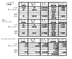
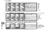
図3aは下記を示す:最初に、それは、14.67−psiaと90−psiaの間での作動の間、第2の圧縮機34(往復式圧縮機であるとされた)の熱力学的性状を示す。圧縮プロセスは等エントロピー的であると考えられ、14.67−psiaおよび華氏70度から、90−psiaおよび華氏426.44度の空気を得ることができる(エントロピー=1.6366BTU/(#R))。しかしながら、圧縮プロセスの効率は84%またはそれ以下と低いことがあり、結果として90−psiaを達成するためにより多くのエネルギーが消費される。その結果、最終温度は実際により高い、つまり、華氏492度またはそれ以上でありえる。圧縮機の水冷および下流の熱交換器35の水冷は、好ましくは出力温度を華氏約70度にする。その後、所望の場合、加熱された水は廃熱利用として湯システムに送ることができるか、あるいは以下に議論されるように結晶化室壁へ送られる。さらに約5−psiの損失のような圧力低下が、第2の圧縮機34とターボ圧縮機31の間にありうることが考慮される。
FIG. 3a shows: Initially, it is the thermodynamics of the second compressor 34 (assumed to be a reciprocating compressor) during operation between 14.67-psia and 90-psia. Shows properties. The compression process is considered to be isentropic, and from 14.67-psia and 70 degrees Fahrenheit, 90-psia and 426.44 degrees Fahrenheit can be obtained (entropy = 1.6366 BTU / (# R) ). However, the efficiency of the compression process can be as low as 84% or less, resulting in more energy being consumed to achieve 90-psia. As a result, the final temperature may actually be higher, i.e., 492 degrees Fahrenheit or higher. The water cooling of the compressor and the water cooling of the
同様のプロセスは、84%の効率で、ターボ圧縮機31(遠心式ガス圧縮機であるとされた)で好ましくは繰り返される。結果は、約43.36BTU/#の流動空気の使用により、85−psiaおよび華氏70度の空気が205−psiaおよび華氏250度に圧縮される。再び、ターボ圧縮機31の水冷および下流の熱交換器37の水冷は、好ましくは出力温度を華氏約70度にする。その後、所望の場合、加熱された水は廃熱利用として湯システムに送ることができるか、あるいは以下に議論されるように結晶化室壁に送られる。さらに約5−psiの損失のような圧力低下が、ターボ圧縮機31とターボ・エキスパンダー33の間にありうることが考慮される。ターボ・エキスパンダー33は、200−psiaおよび華氏70度で入力空気を受理し、約31.5psiaおよび華氏マイナス114.8度の冷却空気を排出できる。これは、43.416BTU/#の流動空気を解放し、ターボ圧縮機31によって要求される43.36BTU/#の流動空気よりも若干多い。
A similar process is preferably repeated with turbo compressor 31 (assumed to be a centrifugal gas compressor) with 84% efficiency. The result is that the use of about 43.36 BTU / # of flowing air compresses 85-psia and 70 degrees Fahrenheit to 205-psia and 250 degrees Fahrenheit. Again, water cooling of the
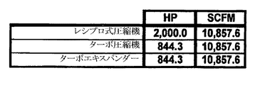
サンプル・ケースは、図3bに示される。そこでは2,000hpシステムは華氏マイナス114.78度で10,857.6のSCFM空気を冷凍目的で供給できる。102.79BTU/#あるいは5.5SCFM/HPの効率で2,000HPの往復運動する第2の圧縮機34だけに動力を供給することにより、これが達成されたことに留意すべきである。図3aでは、2,000hpの電気的入力、および844.3hpの熱出力がある。これは42.2%の効率を示す。
A sample case is shown in Figure 3b. There, the 2,000 hp system is capable of supplying 10,857.6 SCFM air at minus 114.78 degrees Fahrenheit for refrigeration purposes. It should be noted that this was achieved by powering only the
これらの数と量は評価され、例示的な目的だけに示される。実際の使用では、本発明の脱塩システムは、好ましくは華氏マイナス135度から華氏マイナス175度の温度範囲の冷却空気で作動し、したがって、たとえば解放される圧力の量を増加させることによって、より大きな冷却能力があるシステムが本発明によって企図されている。実際の数と量は変わることがある。 These numbers and quantities are evaluated and are shown for exemplary purposes only. In actual use, the desalination system of the present invention preferably operates with cooling air in the temperature range of minus 135 degrees Fahrenheit to minus 175 degrees Fahrenheit, and thus, for example, by increasing the amount of pressure released. Systems with great cooling capacity are contemplated by the present invention. Actual numbers and quantities may vary.
ターボ・エキスパンダーから利用可能な冷たい温度は、200−psiaの入力圧力で、排出圧力が(1)1段階目のターボ・エキスパンダーで30−psiaであり、(2)2段階目のターボ・エキスパンダーで14.67−psiaである例を考えることで一般化することができる。最初のケースでは、30−psiaの排出圧力は下流のプロセスを考慮し、冷却空気は配管とバルブの長い長さを通過し、およびそれらに関連する圧力損失に耐えるために、冷却空気は十分な加圧を必要とする。第2のケースでは、14.67psiaの排出圧力は、下流に任意に重要な配管が無く、またターボ・エキスパンダーを通る時に最も大きな圧力損失(温度降下)を与えることが考慮される。 The cool temperature available from the turbo expander is 200-psia input pressure, the discharge pressure is (1) 30-psia for the first stage turbo expander, and (2) the second stage turbo expander. It can be generalized by considering an example of 14.67-psia. In the first case, the 30-psia discharge pressure allows for downstream processes, and the cooling air is sufficient to pass the long lengths of piping and valves and withstand the associated pressure losses. Requires pressurization. In the second case, the discharge pressure of 14.67 psia is considered to have no significant piping downstream and give the greatest pressure drop (temperature drop) when passing through the turbo expander.
図3cは、上記の2つの特定のケースについて、1ユニットの電力(SCFM/hp)を生成するための気流の必要条件間の大きな違いを示す。図3cは、入力温度がより高くなると、より少ない気流が電力1ユニットを生産するために要求されることを示す。したがって、より高い入力温度は、同じ電力排出時間で与えられた量の電力を生成するために、より少ない圧縮空気エネルギーを要求し、より小さい貯蔵タンクを有する。他方では、図3dはより低い入力温度がより低い排出温度を生産することを示す。更に、図3dは、200−psiaから14.67−psia(大気圧)まで放出する場合、より低い入力温度で非常に低い温度を発生することを示す。したがって、ゴールが脱塩またはエアコンディショニングである場合、より大きな圧力損失およびより冷たい入力温度を考慮することが必要である。 FIG. 3c shows the significant difference between the airflow requirements to generate one unit of power (SCFM / hp) for the two specific cases above. FIG. 3c shows that as the input temperature gets higher, less airflow is required to produce one unit of power. Thus, a higher input temperature requires less compressed air energy and has a smaller storage tank to produce a given amount of power at the same power drain time. On the other hand, FIG. 3d shows that a lower input temperature produces a lower discharge temperature. Furthermore, FIG. 3d shows that when discharging from 200-psia to 14.67-psia (atmospheric pressure), a very low temperature is generated at a lower input temperature. Therefore, if the goal is desalination or air conditioning, it is necessary to consider a larger pressure drop and a cooler input temperature.
B. 本発明の脱塩システムの用途:
本発明の脱塩システムは、脱塩の必要が存在するすべての用途で使用できる。例えば、干ばつ季節にある海岸サイトの近くにある町に真水を供給する必要があることがある。あるいは、砂漠において利用可能な豊富な塩けのある井戸水があることがある。次のセクションでは、2つのユニークな用途が考慮される:
(1) 船適用および(2)島または陸での用途。
船適用では、目的は、電力を使用して真水の生産を最大限にすることである(シナリオ#3を示す図4cを参照)。生産されるどんな電力も循環され、たとえば上記のサージタンク圧縮空気エネルギー・システムの使用によって、空気圧縮機を操作する。島での用途では、電力を最大にするのか、脱塩を最大にするのか、または両者のバランスをとるのかという、1つのシナリオから他のシナリオへ変換する柔軟性が望まれる(図4a、4bおよび4cを参照、それらはシナリオ#1、#2および#3を示す)。
B. Applications of the desalination system of the present invention:
The desalination system of the present invention can be used in all applications where a desalination need exists. For example, it may be necessary to supply fresh water to a town near a coastal site during the drought season. Or there may be abundant salted well water available in the desert. In the next section, two unique uses are considered:
(1) Ship application and (2) Island or land use.
In ship applications, the goal is to use electricity to maximize fresh water production (see FIG. 4c showing scenario # 3). Any power produced is circulated and the air compressor is operated, for example, by use of the surge tank compressed air energy system described above. For island applications, flexibility is desired to convert from one scenario to another, whether to maximize power, maximize desalination, or balance both (Figures 4a, 4b). And 4c, which show
1.船での用途:
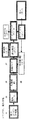
シナリオ#3で見られるように、図4cでは、船に搭載されて利用可能なディーゼル燃料は圧縮機#1、55を操作するために使用できる。圧縮機55は、好ましくは非常に小さなサージタンク57に圧縮空気を供給する。サージタンク57は、ターボ・エキスパンダー61へ供給する1つの出口を有し、次には、非常に冷たい空気を吐き出す。ターボ・エキスパンダー61のシャフトは、ターボ圧縮機ホイール、圧縮機#2、59に好ましくは付けられる。それはローカルの大気の空気を吸入しそれを圧縮し、サージタンク57に圧縮空気を供給できるようにする。したがって、正味のシステムは、圧縮機#1、55を運転するためにディーゼル燃料を使用し、その後過冷却冷却空気を副産物として得る。議論されるように、この過冷却空気は海水と相互作用し、ここに記述された脱塩システムを使用して、純水を生成する。この装置は比較的小さく造ることができ、逆浸透方法のような船で使用される他の既存のシステムと比較された時、著しい量の真水を生成できる。
1. Ship use:
As seen in
この実施態様の変形では、船にマウントされた風力タービン51により、内蔵の船システムも運転されることができ、圧縮機55を運転するために風力により生成されるエネルギーを使用することができる。それが回転でき、いつでも、風の方へ向けることができるように風力タービン51はマウントすることができ、風は船の上のエンジンの電力の代わりに、あるいはそれと組み合わせて、圧縮機を運転するエネルギーを生成するために使用できる。圧縮機55は好ましくはギヤー駆動である。風力タービンからのエネルギーが最初に電気に変換されずに、直接使用され、それは効率を増加させる。
In a variant of this embodiment, the ship-mounted
2. 島およびオフショア用途:
島での用途は、好ましくは電気および/または冷却空気を共−生成するにために上に記述された圧縮空気エネルギー法のうちの任意のものを使用する。第一に、電気だけが必要な期間中には、ヒーターまたは廃熱は、電気の生成を最適化するためにターボ・エキスパンダー61への入力圧縮空気をあらかじめ熱する(華氏約350度まで)ために使用でき、圧縮空気の消費は低減され、ターボ・エキスパンダーからの冷却空気は本質的に使用されない。しかしながら、電気および冷却空気(脱塩とエアコンディショニングの目的のため)の両方が必要な期間中には、熱の入力は好ましくはオフにされる。そのような場合、ターボ・エキスパンダーは、圧縮空気の増加した消費で電気を起こす。また、脱塩および/または冷却装置に供給するために、冷却空気は副産物としてターボ・エキスパンダーから排出される。脱塩システムを通り抜ける冷たい空気もエアコンディショナーに冷却を提供するために使用できる。
2. Island and offshore applications:
Island applications preferably use any of the compressed air energy methods described above to co-generate electricity and / or cooling air. First, during periods when only electricity is needed, the heater or waste heat preheats the input compressed air to the
(a)電気が必要でない場合、および(b)冷却空気が脱塩および/またはエアコンディショニング目的に必要とされる場合、ヒーター入力は好ましくは切られる。好ましくは、上記のサージタンクの「サイクルバック」システムが実施できる。そのような場合、ターボ・エキスパンダー61は好ましくは低減された電力を生成するか、あるいは全く生成しない。また、冷却空気は、ターボ・エキスパンダー61から脱塩システムおよび/または冷却装置に放出される。また、生産されるどんな電力も、往復式圧縮機#2、59を操作するためにサイクルバックされる。この運転モードでは、サージタンクの体積は重要ではない。安定した圧力にタンク57の中が到達し、与えられた圧縮機入力電力が冷却空気の固定フローを出す。圧縮機#1および#2は好ましくは連続的に作動する。
If (a) electricity is not required and (b) cooling air is required for desalination and / or air conditioning purposes, the heater input is preferably turned off. Preferably, the surge tank “cycle back” system described above can be implemented. In such cases,
3. システム・シナリオ:
図4aの中で示されるシナリオ#1では、最小流れ速度で貯蔵タンク57を脱気する一方、電力の最大のレベルを生成することに関心が持たれた。これは、ターボ・エキスパンダー61に供給される加圧された空気を熱するために、近くの設備(あるいは太陽の照射)あるいは圧縮機55からの廃熱を使用することにより遂行できる。より高い初期温度、例えば華氏約300度は、わずかに室温未満であるターボ・エキスパンダー61からの排気空気温度を生産する。したがって、電気は生産されるが、有用な共−生成された冷却空気はない。ターボ・エキスパンダー61のインペラー物質は、回転するインペラーの高い先端速度部分ではチタンであるべきである。
3. System scenario:
In
図4bの中で示されるシナリオ#2では、非常に冷たいターボ・エキスパンダー61からの排気冷却空気および電力を同時に生産すことに関心がある。したがって、空調装置、冷蔵庫、食物ロッカーおよび好ましい実施態様においては脱塩システムにおいて使用できる冷却空気が共−生成される。回転するインペラーの高い先端速度部分は、高い強度のアルミニウムで作られたインペラー材料で作られることが許容可能であり、ターボ・エキスパンダー61は華氏70度より下の温度で作動できる。
In
図4cで示されるシナリオ#3では、電力の生産には関心がない。しかし、ターボ・エキスパンダー61から冷却空気を生産することには関心がある。したがって、空調装置、冷蔵庫、食物ロッカーおよび好ましい実施態様においては脱塩システムにおいて使用できる冷却空気が共−生成される。回転するインペラーの高い先端速度部分は、高い強度のアルミニウムで作られたインペラー材料で作られることが許容可能であり、ターボ・エキスパンダー61は華氏70度より下の温度で作動できる。
In
C. 共晶凍結プロセス:
共晶凍結結晶化方法と呼ばれる既存の技術は、近年関心を呼んだ。塩を含んでいる海水を脱塩する情況では、共晶凍結結晶化プロセスは凍結法の利点を有する。海水溶液の状態図は図20に示される。
C. Eutectic freezing process:
An existing technique called the eutectic freeze crystallization method has attracted interest in recent years. In the context of desalting seawater containing salt, the eutectic freeze crystallization process has the advantage of a freezing method. A phase diagram of the seawater solution is shown in FIG.
純水は0℃(華氏32度)で凍結し始める。しかし、3.5%の塩濃度を有する塩水溶液は約マイナス1.9℃で凍結し始め、生ずる氷は塩を含まず、密度は真水の氷のそれと等しい。塩水の溶液が液体のままである最も低い温度は、マイナス21.1℃あるいは華氏約マイナス6.2度である。塩水の溶液の真水コンポーネントは氷晶(ice crystal)の形成により、その温度に達する前に凍結し始める。しかしその温度において、真水が凍るだけではなく、溶液中の液体が固体に完全に凍るまで、食塩水は氷に加えて純粋なNaCl結晶および水和されたNaCl*2H2Oとして溶液から結晶し始める。凍結された溶液は、凍結された真水氷晶と、NaCl結晶および水和されたNaCl*2H2O結晶の混合物である。より暖かい二相混合物とより冷たい一相の異種混合物の間の境界物質は、共晶混合物と呼ばれる。 Pure water begins to freeze at 0 ° C (32 degrees Fahrenheit). However, an aqueous salt solution having a salt concentration of 3.5% begins to freeze at about minus 1.9 ° C., and the resulting ice is salt-free and the density is equal to that of fresh water ice. The lowest temperature at which the brine solution remains liquid is minus 21.1 ° C. or about minus 6.2 degrees Fahrenheit. The fresh water component of the brine solution begins to freeze before reaching its temperature due to the formation of ice crystals. But at that temperature, not only does the fresh water freeze, but the salt crystallizes out of solution as pure NaCl crystals and hydrated NaCl * 2H 2 O in addition to ice until the liquid in the solution is completely frozen into a solid. start. The frozen solution is a mixture of frozen fresh water ice crystals, NaCl crystals and hydrated NaCl * 2H 2 O crystals. The boundary material between the warmer two-phase mixture and the cooler one-phase heterogeneous mixture is called the eutectic mixture.
水の中に塩溶質だけがある場合、共晶混合物が溶液と平衡にある点は、温度目盛のために素晴らしい較正点を作る。溶質はそれぞれそれ自身の共晶温度および濃度を持っている。これは、二相(真水氷および塩水)と1つの固相の混合物は1つの温度で安定であり、個々の特定の溶質当たり1つの温度でのみ安定しているからである。2−相から1つの固体相までの変化がある場合、温度は、マイナス21.1℃あるいは華氏マイナス6.2度であるに違いない。 If there is only salt solutes in the water, the point where the eutectic mixture is in equilibrium with the solution creates a fine calibration point for the temperature scale. Each solute has its own eutectic temperature and concentration. This is because a mixture of two phases (fresh water ice and salt water) and one solid phase is stable at one temperature and only stable at one temperature per individual specific solute. If there is a change from 2-phase to one solid phase, the temperature must be minus 21.1 ° C. or minus 6.2 degrees Fahrenheit.
共晶凍結結晶化プロセスの工程のシーケンスは、図20の中で示されるような、典型的な水−塩状態図に基づいて説明できる。塩水の溶液が、液相境界線によって示された凍結温度以下に冷却されれば、氷晶が生じ始める。この線は傾いており、塩水の溶液の凍結温度がその内部の塩濃度のレベルに依存することを示す。例えば、塩濃度が0パーセントである場合、凍結温度は華氏32度である。しかしながら、塩の濃度レベルが増加する場合、液相境界線に沿って下へ移動することによって、氷晶が生ずる温度は減少する。例えば、溶液が10パーセントの塩濃度である場合、凍結温度はより低くつまり、15〜20°F程度低くなる。その後継続された冷却により、より多くの氷が形成され、塩水の溶液はもっと濃くなる。したがって、その組成は液相境界線に沿って移動し、共晶点と呼ばれるポイントに結局達し、そこでは、溶液は塩で飽和され、塩の濃度は23.3%となる。この濃度では、温度が、華氏約マイナス6.2度の共晶温度で、氷晶が生ずる。華氏マイナス6.2度未満にさらに冷却すると、3つの固体の混合物の形成に帰着する:1)固体の純水氷晶、2)固体の純粋な塩の結晶および3)分離されない単一相中の固体の純粋な水和塩の結晶。NaClの共晶点は華氏マイナス6.2度である。また、共晶組成は23.3%である。 The sequence of steps of the eutectic freeze crystallization process can be described based on a typical water-salt phase diagram, as shown in FIG. When the brine solution is cooled below the freezing temperature indicated by the liquidus boundary, ice crystals begin to form. This line is tilted, indicating that the freezing temperature of the brine solution depends on the level of salt concentration within it. For example, if the salt concentration is 0 percent, the freezing temperature is 32 degrees Fahrenheit. However, as the salt concentration level increases, the temperature at which ice crystals form decreases by moving down along the liquidus boundary. For example, if the solution has a salt concentration of 10 percent, the freezing temperature is lower, that is, as low as 15-20 ° F. Subsequent cooling causes more ice to form and the brine solution to become thicker. Thus, its composition moves along the liquidus boundary and eventually reaches a point called the eutectic point, where the solution is saturated with salt and the salt concentration is 23.3%. At this concentration, ice crystals form at a eutectic temperature of about minus 6.2 degrees Fahrenheit. Further cooling to less than minus 6.2 degrees Fahrenheit results in the formation of a mixture of three solids: 1) solid pure water ice crystals, 2) solid pure salt crystals and 3) in an unseparated single phase Solid pure hydrate salt crystals. The eutectic point of NaCl is minus 6.2 degrees Fahrenheit. The eutectic composition is 23.3%.
本発明では、氷塊は、好ましくは塩の結晶化を回避するためにわずかにこの温度より上の温度で操作される。したがって、固相境界線の上の領域(23%の塩濃度より下)だけが好ましく使用される。それはEFC温度の上の状態図の領域を表わす。状態図の左へ遠く離れた領域(0%の塩)は、純粋な氷/雪形成を表わす。また、中央部は塩気のあるブラインを表わす。状態図の右へ遠く離れた領域、および固相境界線より下の領域は、分離を許さず、本発明のシステムでは使用されない、単一の固相の純粋な固体「塩および水和水」結晶、および純粋な固体の結晶を含んでいる。 In the present invention, the ice mass is preferably operated at a temperature slightly above this temperature to avoid salt crystallization. Therefore, only the region above the solid phase boundary (below 23% salt concentration) is preferably used. It represents the region of the phase diagram above the EFC temperature. The area far to the left of the phase diagram (0% salt) represents pure ice / snow formation. Further, the central part represents a salty brine. The region far to the right of the phase diagram, and the region below the solid phase boundary, does not allow separation and is not used in the system of the present invention, a single solid phase pure solid “salt and hydrated water” Crystal, and pure solid crystal.
パシフィックノースウエスト研究所のハーマン チョー(Herman Cho)博士によって行なわれたNMRテストは、食塩水が共晶温度以下に凍結される場合、共晶温度より暖かく溶かされた時に、それが2相状態に「直ちに」戻ることを示した。これは、結晶化室内の非常に小さな小滴の振る舞いについて記述するための重要なデータポイントである。 An NMR test conducted by Dr. Herman Cho at Pacific Northwest Laboratories showed that when saline was frozen below the eutectic temperature, it was in a two-phase state when it was melted warmer than the eutectic temperature. Immediately indicated to return. This is an important data point for describing the behavior of very small droplets in the crystallization chamber.
図7の中で示されるように、海洋からの標準海水が塩以外の追加のミネラルおよび不純物を含むことはさらに考慮されるべきである。図7は、海水の標準組成を示す。各成分について、重量パーセントと共晶温度が与えられる。一方、図8は、清浄な飲料水用の必要条件を表わす。通常、海水中の3%の塩濃度は、0.03%の塩濃度にされた時、飲用に適していると考えられる。真水は0.05%より下の任意の塩濃度であると考えられる。しかし、用語「汽水」は0.05%〜3.0%の塩性の濃度を有する水について一般に用いられる。用語「塩性水」は3.0%〜5.0%の塩濃度を有する水について一般に用いられる。また、用語「ブライン」は5.0%以上の塩濃度を有する水について一般に用いられる。再び、用語「海水」は、浄化される必要がある任意の水であって、海またはそれ以外から得られるものを含む。 It should be further considered that standard seawater from the ocean contains additional minerals and impurities other than salt, as shown in FIG. FIG. 7 shows the standard composition of seawater. For each component, the weight percent and eutectic temperature are given. On the other hand, FIG. 8 represents the requirements for clean drinking water. Normally, a salt concentration of 3% in seawater is considered suitable for drinking when brought to a salt concentration of 0.03%. Fresh water is considered to be any salt concentration below 0.05%. However, the term “brackish water” is generally used for water having a salty concentration of 0.05% to 3.0%. The term “saline water” is generally used for water having a salt concentration of 3.0% to 5.0%. The term “brine” is generally used for water having a salt concentration of 5.0% or more. Again, the term “seawater” includes any water that needs to be purified and is obtained from the sea or otherwise.
塩化ナトリウム(NaCl)を抽出するためにマイナス21.2℃(あるいは華氏マイナス6.2度)の共晶温度を使用することによって、結晶化プロセスは次のミネラルを残すということに注意すべきである:塩化カルシウム(1.36g/取込量の1リットル)および塩化マグネシウム(4.66g/取込量の1リットル)。これらはさらに経済的便益のために取り出すことができる2つの製品である。塩化カリウム、硫酸マグネシウムおよび重炭酸ナトリウムのような他のミネラルをさらに回収することに関心があれば、スラッシュ温度のより注意深いコントロールを保証し、これらの化合物が氷内で凍結しないで、代わりに補足処理中で後に回収するために回収用のブライン溶液に残す。新鮮な飲料水が最終目標である場合、本発明はそれが脱塩プロセスの中で使用される前に海水からできるだけ多くの不純物を回収するためにフィルタを使用することを企図する。本発明は他の任意のミネラルをさらに経済的便益のために使用することを企図する。 It should be noted that by using a eutectic temperature of minus 21.2 ° C. (or minus 6.2 degrees Fahrenheit) to extract sodium chloride (NaCl), the crystallization process leaves the following minerals: There are: calcium chloride (1.36 g / liter of uptake) and magnesium chloride (4.66 g / liter of uptake). These are two products that can be taken out for further economic benefits. If you are interested in further recovering other minerals such as potassium chloride, magnesium sulfate and sodium bicarbonate, ensure a more careful control of slush temperature and these compounds will not freeze in ice, supplemented instead Leave in recovery brine solution for later recovery in process. Where fresh drinking water is the ultimate goal, the present invention contemplates using a filter to recover as much impurities as possible from seawater before it is used in the desalination process. The present invention contemplates the use of any other mineral for further economic benefits.
EFC方法についてはほとんど情報は発行されていない。蒸発および冷却結晶化のような、競合する従来の技術と比較して、EFCの申し立てられた複雑さによるのかもしれない。洗浄カラム技術の進行中の進歩により、および超浄化技術としての溶解結晶化の大規模適用で、EFCの最も大きな欠点の投資コストおよび規模制限は克服できる。その商用適用を考慮するための時期が来た。 Little information has been published on the EFC method. It may be due to the alleged complexity of the EFC compared to competing conventional technologies such as evaporation and cold crystallization. With ongoing progress in wash column technology, and with large scale application of dissolution crystallization as a super purification technology, the investment costs and scale limitations of EFC's biggest drawbacks can be overcome. The time has come to consider its commercial application.
上に議論されるように、本発明のEFCプロセスは、それがベース水の中にある不純物から分離できる純水氷晶の形成を含んでいるという点で他のプロセスとは異なる。小滴が凍結して固体の氷粒子状物質および液体のブラインの二相の溶液を形成することは重要である。したがって、小滴が飛行中に共晶温度あるいはその共晶温度の近くに小滴が達することは望ましい。他方では、小滴らが室を通って落ちる時に、小滴が冷たくなりすぎる(共晶温度より冷たい)場合、各小滴内の真水は固体の塩の結晶および固体のブラインと一緒に凍結できる。その場合には、真水から塩を分離することは可能ではないことがある。 As discussed above, the EFC process of the present invention differs from other processes in that it includes the formation of pure water ice crystals that can be separated from impurities present in the base water. It is important that the droplets freeze to form a two-phase solution of solid ice particulates and liquid brine. Therefore, it is desirable for the droplets to reach or near the eutectic temperature during flight. On the other hand, if the droplets get too cold (cooler than the eutectic temperature) as they drop through the chamber, the fresh water in each droplet can be frozen together with solid salt crystals and solid brine. . In that case, it may not be possible to separate the salt from fresh water.
例えば、海水スプレーが、様々な小滴サイズから成る場合、このようなことが起こることがある。そこではより小さな小滴は共晶温度以下に達することがあり、それらが室の底に達する時までに完全に凍ることがある。この点で、直径で平均サイズ4,000ミクロン近くの雲を分散させるように設計されたスプレーノズルは、より小さい分率ではあるが多量の直径で400ミクロンの範囲中の物質フローをも形成することに留意すべきである。これらのより小さな粒子状物質は10分の1のより小さな沈降速度を持っており、10倍のより長い滞留時間を持つ。更に、並流構成中のノズルを出る華氏マイナス135度あるいは華氏マイナス175度の局所的な気流と相互作用する時、これらのより小さな粒子状物質は、共晶温度より下の温度に早く到達し、より速く凍結する。たとえ典型的なノズルがより大きな直径の粒子状物質をスプレーしても、ある範囲内の粒径の分布を含み、より小さな粒子状物質が常に存在する。より小さな粒子状物質は数において大きいが、全体としては非常に大きな量として寄与しない。 For example, this can happen if the seawater spray consists of various droplet sizes. There, smaller droplets can reach below the eutectic temperature and freeze completely by the time they reach the bottom of the chamber. In this regard, spray nozzles designed to disperse clouds with an average size close to 4,000 microns in diameter also produce a material flow in the 400 micron range with a large fraction of diameters. It should be noted. These smaller particulates have a smaller settling rate of 1/10 and have a tenfold longer residence time. In addition, these smaller particulates quickly reach temperatures below the eutectic temperature when interacting with local airflows of minus 135 degrees Fahrenheit or minus 175 degrees Fahrenheit exiting nozzles in a co-current configuration. Freeze faster. Even if a typical nozzle sprays larger diameter particulate matter, there will always be a smaller particulate matter containing a distribution of particle sizes within a certain range. Smaller particulates are large in number, but overall they do not contribute as very large quantities.
したがって、この非常に冷たい温度領域における下方への飛行中での小さな小滴は、確かに、(1)真水の固体の氷、(2)2つの水分子と結合された各塩分子と水分子を有する固体の塩および(3)固体の塩の結晶から構成される1つの固形微粒子への小滴の望ましくない結晶化を引き起こす。冷たい空気中の小さな粒子の飛行中に、真水からのブラインの分離はない。しかしながら、以下に議論されるように、好ましくは共晶温度より暖かい平衡温度を持っている、室の底部の大きな粒子から生成された氷粒子状物質の塊上に小滴が堆積したときに分離が生じる。 Thus, the small droplets in the downward flight in this very cold temperature region are indeed (1) solid ice, (2) each salt molecule and water molecule combined with two water molecules. And (3) undesired crystallization of the droplets into one solid particulate composed of crystals of the solid salt. There is no separation of brine from fresh water during the flight of small particles in cold air. However, as discussed below, separation occurs when the droplets accumulate on a mass of ice particulate material generated from large particles at the bottom of the chamber, preferably having an equilibrium temperature warmer than the eutectic temperature. Occurs.
共晶温度よりはるかに冷たい空気温度に、スプレーノズルに近い領域で露出された時、直径で数百ミクロンのオーダーの非常に小さな粒子は、それらの中心まで完全に凍結することがある。これらの小さな小滴が、結晶化室の底のより暖かい氷/雪塊上に堆積する場合、それらは、共晶点よりわずかに暖かい平衡温度周辺に好ましくは暖められる。したがって、小さな小滴が共晶温度以下で凍結する場合、それらは共晶温度以上で溶かすことができる。そのポイントでは、固体の多孔性の雪/氷構造および液体の食塩水(ブライン)の通常の分離が生じる。したがって本発明のプロセスにおいては、少なくとも室の底において、結晶化温度は、塩結晶化を回避するために、共晶凍結結晶化温度の若干上のレベルで好ましくは維持される。最終結果は、純粋な氷/雪および残液ブラインの形成である。 When exposed to air temperatures much cooler than the eutectic temperature in areas close to the spray nozzle, very small particles on the order of a few hundred microns in diameter may freeze completely to their centers. If these small droplets are deposited on the warmer ice / snow mass at the bottom of the crystallization chamber, they are preferably warmed around an equilibrium temperature slightly warmer than the eutectic point. Thus, if small droplets freeze below the eutectic temperature, they can be melted above the eutectic temperature. At that point, normal separation of solid porous snow / ice structures and liquid saline (brine) occurs. Thus, in the process of the present invention, at least at the bottom of the chamber, the crystallization temperature is preferably maintained at a level slightly above the eutectic freeze crystallization temperature to avoid salt crystallization. The end result is the formation of pure ice / snow and residual brine.
共晶温度での結晶化室の操作は、海水の85.7%の真水への高い転化に帰着する。しかしながら、氷/雪塊の孔隙率はわずかに暖かい温度でより高いことがあり、最終真水の高純度を得るために85.7%未満へと変換効率が犠牲にされる。 Operation of the crystallization chamber at the eutectic temperature results in a high conversion of seawater to 85.7% fresh water. However, the porosity of the ice / snow lump may be higher at slightly warmer temperatures, at the expense of conversion efficiency to less than 85.7% to obtain high purity of the final fresh water.
本発明はEFCシステムの新規な変形を示す。清潔な冷却空気は冷媒として使用され、海水の小滴雲と混合され、海水を共晶点の近くに達っせしめ、その結果純水氷晶が形成できる。それは、氷凍結の後に残る塩気のあるブライン溶液から取り除くことができる。本発明では、特に氷晶が沈降し始める場合、システムはほとんど共晶点より上で操作されることが意図される。その結果、固体の塩の結晶の形成は回避できる。 The present invention represents a novel variant of the EFC system. Clean cooling air is used as a refrigerant and mixed with seawater droplets to bring the seawater close to the eutectic point, resulting in the formation of pure water ice crystals. It can be removed from the salty brine solution that remains after ice freezing. In the present invention, it is intended that the system be operated almost above the eutectic point, especially when ice crystals begin to settle. As a result, the formation of solid salt crystals can be avoided.
本発明のゴールのうちの1つは、混合室内に海水と導入され混ぜ合わせられた冷却空気への接触によって、海水が十分に凍結されることを保証することである。これをするために、本発明は非常に冷えた空気を混合室内へ導入することを企図する。たとえば冷却された空気は好ましくは華氏マイナス175度からマイナス135度Fの間にされ、ついで海水を加圧してノズルを介して混合室内に射出し、小さな海水小滴の形とし、より容易に冷却空気によって混合され、冷却され、影響される。また、適切な凍結および分離が生じる場合が起こることを保証するために、サイズ、小滴のサイズと速度、およびそれらがどのように作られ冷却空気フロー中に導入されるか、並びに温度、冷却空気の体積流速および相対的な方向、混合室のサイズを決定することは重要である。 One of the goals of the present invention is to ensure that the seawater is sufficiently frozen by contact with the cooling air introduced and mixed with the seawater in the mixing chamber. To do this, the present invention contemplates introducing very cold air into the mixing chamber. For example, the cooled air is preferably between minus 175 degrees Fahrenheit and minus 135 degrees Fahrenheit, then the seawater is pressurized and injected through a nozzle into the mixing chamber to form small seawater droplets that cool more easily Mixed by air, cooled and affected. Also, to ensure that proper freezing and separation occurs, the size, the size and speed of the droplets, how they are made and introduced into the cooling air flow, and the temperature, cooling It is important to determine the volumetric flow rate and relative direction of the air and the size of the mixing chamber.
図9は、水小滴の種々相のための温度領域を示す。その発見者のトルバーゲロン(Tor Bergeron)にちなんで命名されたバーゲロンプロセスは過冷却水小滴を含んでいる。「過冷却」の用語は、摂氏0度あるいは華氏32度の凝固点より下の温度でまだ液体である水を指す。研究は、雲核のサイズのような非常に小さいサイズで水が存在する場合には、凍結温度以下(マイナス40℃あるいは華氏マイナス40度)の温度で存在できることを示した。 FIG. 9 shows the temperature range for the various phases of the water droplet. The Bergeron process, named after its discoverer Tor Bergeron, contains supercooled water droplets. The term “supercooled” refers to water that is still liquid at temperatures below the freezing point of 0 degrees Celsius or 32 degrees Fahrenheit. Studies have shown that when water is present in very small sizes, such as the size of cloud nuclei, it can exist at temperatures below the freezing temperature (minus 40 ° C or minus 40 degrees Fahrenheit).
本発明は、冷却空気を海水小滴と混合するために、図14−18および25−31の中で示されるもののような混合室を好ましくは利用する。混合室は、好ましくは本質的に絶縁された壁を有するコンテナである。その中で共晶温度の近く(わずかに上に)まで達するまで、海水小滴および冷却空気が導入され混ぜ合わせられることができる。共晶温度は上述のように塩水では、マイナス21.1℃である。室のサイズおよび構成は以下に議論されるように、所望のニーズおよびキャパシティーに依存して変わることができる。 The present invention preferably utilizes a mixing chamber such as that shown in FIGS. 14-18 and 25-31 to mix cooling air with seawater droplets. The mixing chamber is preferably a container with essentially insulated walls. In it, seawater droplets and cooling air can be introduced and mixed until near the eutectic temperature (slightly above). The eutectic temperature is minus 21.1 ° C. in salt water as described above. The size and configuration of the chamber can vary depending on the desired needs and capacity, as discussed below.
適切な混合が生じることを保証するのを支援するために、海水は好ましくは加圧されスプレーを形成するために1つ以上のノズルを通して移動される。それは、室へ好ましくは導入される海水小滴雲、またはミストを形成する。達成されるべき所望の結果に依存して、様々なノズル構成のうちの任意のものが可能である。 To help ensure that proper mixing occurs, the seawater is preferably pressurized and moved through one or more nozzles to form a spray. It forms a seawater droplet cloud, or mist, which is preferably introduced into the chamber. Depending on the desired result to be achieved, any of a variety of nozzle configurations is possible.
フルコーン・ノズルは、円形、楕円形、四角いエリアの完全なスプレー範囲を形成する。通常、液体はノズル内で渦巻き、内部翼をバイパスした非回転液体と混合される。その後、液体はオリフィスを通り、円錐形のパターンを形成する。コーン・パターン内の噴射角度および液体の分布は、翼設計と出口オリフィスに対する位置に依存する。出口オリフィス設計および相対的な幾何学的な比率はさらに噴射角度と分布に影響する。フルコーン・ノズルはメディアの均一なスプレー分布を供給し、大きなフロー通過および制御特性を特色とするそれらの翼設計に起因して大きなサイズの小滴を提供する。 Full cone nozzles form a complete spray area of circular, oval and square areas. Typically, the liquid is mixed with non-rotating liquid that swirls within the nozzle and bypasses the inner wing. The liquid then passes through the orifice to form a conical pattern. The spray angle and liquid distribution within the cone pattern depends on the blade design and position relative to the exit orifice. The exit orifice design and relative geometric ratios further affect the injection angle and distribution. Full cone nozzles provide a uniform spray distribution of media and provide large size droplets due to their wing design featuring large flow passage and control characteristics.
図10は、スプレーノズルのいくつかの特性を示す。フルコーンの構成は本発明において最も使用可能である。各タイプのスプレーパターン内において、最も小さなキャパシティーは、最も小さなスプレー液滴を生産する。ここで、キャパシティーはオリフィス直径が小さい場所でオリフィスを横切る最低の圧力損失によって定義される。最大のキャパシティーは最大のスプレー液滴を生産する。ほとんどのノズルにおいて、一連の異なるサイズ小滴の分布が必然的に形成される。例えば、4,000ミクロンの直径のVMDを有するノズルは4,000ミクロンで小滴の最大のマスフローを持つ。しかしながら、直径400ミクロンのより小さなサイズで、粒子のはるかに小さなマスフローがさらにある。体積平均粒子直径(VMD)はスプレーされた液体の体積に基づく;したがって、それは広く容認された手段である。図11は、ノズル・タイプによって可能な小滴サイズの範囲を示す。 FIG. 10 shows some characteristics of the spray nozzle. The full cone configuration is most usable in the present invention. Within each type of spray pattern, the smallest capacity produces the smallest spray droplets. Here, capacity is defined by the lowest pressure drop across the orifice where the orifice diameter is small. Maximum capacity produces the largest spray droplet. In most nozzles, a series of different size droplet distributions are inevitably formed. For example, a nozzle with a 4,000 micron diameter VMD has a maximum mass flow of droplets of 4,000 microns. However, there is also a much smaller mass flow of particles at a smaller size of 400 microns in diameter. Volume average particle diameter (VMD) is based on the volume of liquid sprayed; it is therefore a widely accepted means. FIG. 11 shows the range of possible droplet sizes depending on the nozzle type.
本発明の1つの実施態様においては、入力海水と冷却空気とが混合される。1分当たり約250ポンド(250#/分)の海水が前もって定義した量の冷却空気で処理することができ、これは約7,151標準立法フィート/分(7,151SCFM)と計算できる。そのような場合、約214#/分の氷(真水)が理想的に回収される。9.9SCFM/hpのターボ・エキスパンダー効率および2.2SCFM/hpの圧縮機効率に基づいて、真水を1分当たり1ポンド生成するために7.1kWの入力電力が必要である。 In one embodiment of the present invention, input seawater and cooling air are mixed. Approximately 250 pounds per minute (250 # / min) of seawater can be treated with a pre-defined amount of cooling air, which can be calculated as approximately 7,151 standard cubic feet per minute (7,151 SCFM). In such a case, about 214 # / min of ice (fresh water) is ideally recovered. Based on a turbo expander efficiency of 9.9 SCFM / hp and a compressor efficiency of 2.2 SCFM / hp, 7.1 kW of input power is required to produce 1 pound of fresh water per minute.
120分で11,000ポンドの塩水を移送するために、選択されたスプレーノズルは最小10.76ガロン/分を通過させなければならない。したがって、そのサンプル実施態様には、12ガロン/分および4,300ミクロンのVMDの能力を有するフルコーン・ノズルを適用することができる。激しい降雨は2,000〜5,000ミクロンのVMDを有する粒子から成ることに留意されたい。向かい風に対した時、直径8,000ミクロン以上の小滴はフラグメントに分割される。この例において、体積流速は、ノズルのサイズおよび運転圧を始めとする装置の設計を指示できる。そしてしたがって、真水生産の所望の速度が必要な時に海水小滴のサイズを指示できる。他の例において、ノズルのサイズおよび海水小滴サイズは、真水の生産における設備の最高効率のために、達成することが求められる最適の特性に基づいて決定できる。 To transfer 11,000 pounds of salt water in 120 minutes, the selected spray nozzle must pass a minimum of 10.76 gallons / minute. Thus, a full cone nozzle having the capacity of 12 gallons / minute and VMD of 4,300 microns can be applied to the sample embodiment. Note that heavy rainfall consists of particles having a VMD of 2,000 to 5,000 microns. When headed against the headwind, droplets larger than 8,000 microns in diameter break up into fragments. In this example, the volume flow rate can dictate the design of the device, including nozzle size and operating pressure. Thus, the size of the seawater droplets can be indicated when the desired rate of fresh water production is required. In another example, the nozzle size and seawater droplet size can be determined based on the optimum characteristics that are sought to be achieved for maximum efficiency of the facility in the production of fresh water.
海水小滴のサイズは好ましくはできるだけコントロールされ、予め決定され、適切な混合および適切な伝熱を保証し、適切な凍結が起こることを保証することを助ける。好ましくは、小滴は、小滴の外側表面から小滴の核まで完全に凍るまで非常に短い量だけを必要とする。その例は図12で見ることができる。これは小滴サイズ、温度、および冷却空気の体積流量速度および方向(それは室のサイズの関数である)、小滴が冷却空気に暴露される時間(つまり滞留時間)の関数でありえる。小滴は速く凍結されることができるほど十分に小さいが、それらが、冷却空気の流量にかかわらず、室の底に結局落ちる程度に十分に大きくなければならない。 The size of the seawater droplets is preferably controlled as much as possible and predetermined to help ensure proper mixing and proper heat transfer and ensure that proper freezing occurs. Preferably, the droplet only requires a very short amount until it completely freezes from the outer surface of the droplet to the core of the droplet. An example of this can be seen in FIG. This can be a function of droplet size, temperature, and volumetric flow rate and direction of the cooling air (which is a function of chamber size), and the time the droplet is exposed to cooling air (ie, residence time). The droplets are small enough that they can be frozen quickly, but they must be large enough so that they eventually fall to the bottom of the chamber, regardless of the cooling air flow rate.
概して言えば、小滴サイズは、ノズルを通ることを海水を強要するために使用される圧力の量によって影響される場合がある。より多くの圧力が使用される時、小滴直径はより小さくなる傾向がある。また、より少ない圧力が使用される時、小滴直径はより大きくなる傾向がある。例えば、約28psiaの圧力が使用される時、小滴は比較的小さくなる傾向があり、14.67psiaの大気中への、約26フィート/秒の下方向への速度に帰着する。一方、たとえば約16psiaのより低い圧力では、小滴は大きくなる傾向があり、14.67psiaの大気中への、約8.3フィート/秒の下方向への速度に帰着する。しかしながら、ほとんどのノズルで、形成される海水小滴のサイズを完全にコントロールすることは必ずしも可能ではない。したがって、本発明は、スプレーが作られる時一連の小滴サイズが形成される可能性を考慮に入れなければならない。しかしながら、ノズルは特定の名目上の小滴サイズのために設計されている。統計的に、名目上の小滴サイズは典型的な鐘形の分布を有する中央値(VMD)になる。良質に生産されたノズルについては、大多数の粒径が中央値に近いように、正規分布は、比較的狭く、高いピークを有するようになる。中間値よりも大きいか又は小さい外側のサイズ領域は、脱塩システム性能に重要な影響がなかった。 Generally speaking, the droplet size may be affected by the amount of pressure used to force seawater through the nozzle. As more pressure is used, the droplet diameter tends to be smaller. Also, when less pressure is used, the droplet diameter tends to be larger. For example, when a pressure of about 28 psia is used, the droplets tend to be relatively small, resulting in a downward velocity of about 26 feet / second into the atmosphere at 14.67 psia. On the other hand, for example, at lower pressures of about 16 psia, the droplets tend to be larger, resulting in a downward velocity of about 8.3 feet / second into the atmosphere at 14.67 psia. However, with most nozzles it is not always possible to completely control the size of the seawater droplets formed. Therefore, the present invention must take into account the possibility of a series of droplet sizes being formed when a spray is made. However, the nozzle is designed for a specific nominal droplet size. Statistically, the nominal droplet size becomes the median (VMD) with a typical bell-shaped distribution. For nozzles produced in good quality, the normal distribution is relatively narrow and has a high peak so that the majority of particle sizes are close to the median. The outer size region that is larger or smaller than the median value had no significant effect on the desalination system performance.
別の考察は室内での冷却空気の流速である。小滴サイズと共に、小滴がどれくらいの時間冷却空気に露出され冷却空気内に保留されるか、またそれがどのように混合室内を循環するかは、小滴と冷却空気の相対速度に依存する。すなわち、小滴が室の底に落ちる速度は、以下に議論されるように、室内の冷却空気の方向および流速を調節することにより変えることができる。この点で、室内へ導入されている海水スプレーおよび冷却空気の相対的な方向は、氷晶の適切な形成に寄与できる。この点で、本発明は1)向流および2)並流配置の両方を企図している。 Another consideration is the flow rate of the cooling air in the room. Along with the droplet size, how long the droplet is exposed to and retained in the cooling air and how it circulates in the mixing chamber depends on the relative velocity of the droplet and the cooling air. . That is, the rate at which the droplets fall to the bottom of the chamber can be varied by adjusting the direction and flow rate of the cooling air in the chamber, as will be discussed below. In this regard, the relative direction of the seawater spray and cooling air introduced into the room can contribute to the proper formation of ice crystals. In this regard, the present invention contemplates both 1) countercurrent and 2) cocurrent arrangements.
D. 向流:
向流配置を達成するため、冷却空気および海水スプレーが反対向きに室へ導入される。
これは、例えば冷却空気が室へ上向きに導入される一方、室へ海水を下向きにスプレーすることにより達成できる。この配置は図16−18および25−30に示される。海水の下方向きのスプレーおよび冷却空気の上向きのフローを使用する向流では、小滴が室の内を循環し、凍り、沈降する途中での相対するフローの影響を考慮することは重要である。どちらの例でも、2つの流れの間の速度の違い、重力の影響、小滴のサイズ、および冷却空気フローの温度および体積速度、ならびに室のサイズは、海水小滴が十分に循環できる範囲を決定するのを助け、適当な冷却および凍結、並びに小滴の沈降が達成できる。さらに、それらは室の底部に落下し、かなり短い時間、すなわち数秒未満で氷塊を形成し始める。
D. Counterflow:
In order to achieve a countercurrent arrangement, cooling air and seawater spray are introduced into the chamber in opposite directions.
This can be accomplished, for example, by spraying seawater downward into the chamber while cooling air is introduced upward into the chamber. This arrangement is shown in FIGS. 16-18 and 25-30. In counterflow using downward spray of seawater and upward flow of cooling air, it is important to consider the effects of opposing flows as the droplets circulate in the chamber, freeze and settle . In both examples, the difference in velocity between the two streams, the influence of gravity, the droplet size, and the temperature and volume velocity of the cooling air flow, and the chamber size are within the range that the seawater droplets can circulate well Helping to determine, proper cooling and freezing, and droplet settling can be achieved. Furthermore, they fall to the bottom of the chamber and begin to form ice blocks in a fairly short time, i.e. less than a few seconds.
従って、向流を考慮する場合、それが上向きの冷却空気フローにさらされているので、海水小滴の最終の降下速度を考慮しなければならない。空気中の水小滴のための最終降下速度の相関性は、図13に示される。より小さな直径粒子状物質(直線の下で示される)は、多くの場合に上方へ吹き上げられて、システムから吹き出される。したがって、小さすぎる小滴を生まないように、スプレーのノズル構成が好ましくは形成される。しかしながら、ほとんどのノズルで、ある量の海水小滴は、小さなミスト状の小滴のスプレーとして必然的に形成される。これは好ましくは海水出力の非常に小さな分率であるが、それは上方へ吹き上げられる傾向がある。 Therefore, when considering counterflow, the final drop rate of the seawater droplets must be considered because it is exposed to upward cooling air flow. The correlation of final descent rate for water droplets in air is shown in FIG. Smaller diameter particulate matter (shown below the straight line) is often blown upward and blown out of the system. Thus, a spray nozzle configuration is preferably formed so as not to produce droplets that are too small. However, with most nozzles, a certain amount of seawater droplets is inevitably formed as a spray of small mist droplets. This is preferably a very small fraction of seawater output, but it tends to be blown up.
約7,151SCFMの冷却空気の使用し、25平方フィートの断面積を有する直立のカラムを有する室を使用することが考慮される。そこでは冷却空気の上向きの垂直速度は約4.77 フィート/秒であるとわかった。そのような場合、図13で支持されるデータを考慮に入れることによって、325ミクロン以上である海水小滴が、その速度の上向きの冷却空気フローを通り、恐らく適切にゆっくりと沈降することが決定された。しかしながら、図13の中のチャートを見ると、直径4,000ミクロンのサイズを持つ海水小滴で、44フィート/秒の冷却空気速度が、より好ましいと考えられる。ワ ガオ(Wa Gao)博士は、彼女の垂直の風洞の中で、華氏マイナス4度の冷却空気を使用して、約7秒の平均時間で、豚飼育場廃水の2,800および4,200ミクロンのサイズ小滴を凍結することを報告した。しかしながら本発明では、海水小滴は、室温(つまり華氏40度)から華氏マイナス6.2度(共晶温度)近傍で好ましくは凍結され、非常に短い時間、約0.2秒で凍結される。冷却空気が華氏マイナス135度から華氏マイナス175度で使用されるからである。 It is contemplated to use a chamber with upright columns having a cross-sectional area of 25 square feet, using approximately 7,151 SCFM of cooling air. There it was found that the upward vertical velocity of the cooling air was about 4.77 feet / second. In such a case, taking into account the data supported in FIG. 13, it is determined that seawater droplets that are 325 microns and larger will pass through the upward cooling air flow at that velocity, and possibly settle down appropriately and slowly. It was. However, looking at the chart in FIG. 13, a cooling air velocity of 44 feet / second would be more preferred for seawater droplets having a size of 4,000 microns in diameter. Dr. Wa Gao uses 2,800 and 4,200 pig farm effluents in her vertical wind tunnel, using -4 degrees Fahrenheit cooling air, with an average time of about 7 seconds. It was reported that micron size droplets were frozen. However, in the present invention, the seawater droplets are preferably frozen from room temperature (ie, 40 degrees Fahrenheit) to around minus 6.2 degrees Fahrenheit (eutectic temperature) and are frozen in a very short time, about 0.2 seconds. . This is because the cooling air is used at minus 135 degrees Fahrenheit to minus 175 degrees Fahrenheit.
4,000ミクロンのオーダーの直径のより大きな小滴サイズについては、同じ温度の冷却空気が使用されると仮定して、芯まで小滴を凍結するのに0.2秒を越える時間がかかる。最初は、小滴が華氏+40度にあり、空気が華氏マイナス175度とマイナス135度の間にある場合、強い伝熱があり、わずか0.2秒しか必要でない。しかしながら、小滴の温度が低くなると熱交換が起こり、局所的に空気の温度が上がるので、この計算は完全に正確ではない。更に、小滴が適切な熱交換を保証するために必要なすべての空気と相互作用すると仮定されている。しかしながら、ガオ博士によって報告された小滴凍結データは、より暖かい気流の中での個々の小滴の短い凝固時間を支援する。向流室での滞留時間用の例を考察する。そこでは直径4,000ミクロンで44フィート/秒の下方への沈降速度を有する小滴は、室内での4フィート/秒の冷却空気のより遅い上向きの速度に遭遇する。小滴は、10フィート/(44フィート/秒− 4フィート/秒)で、10フィートの垂直の高さを0.25秒で落ちる。したがって、より大きな小滴は、それらが氷/雪塊上に堆積し、熱交換を完了し、華氏マイナス6度の平衡温度に到達するまで、それらは必要な熱交換を完了しないことが期待される。 For larger droplet sizes on the order of 4,000 microns in diameter, it takes more than 0.2 seconds to freeze the droplets to the core, assuming that the same temperature of cooling air is used. Initially, if the droplet is at +40 degrees Fahrenheit and the air is between minus 175 degrees Fahrenheit and minus 135 degrees Fahrenheit, there is strong heat transfer and only 0.2 seconds are required. However, this calculation is not completely accurate because heat exchange occurs when the temperature of the droplets is lowered and the temperature of the air locally increases. Furthermore, it is assumed that the droplets interact with all the air necessary to ensure proper heat exchange. However, the droplet freezing data reported by Dr. Gao supports short clotting times for individual droplets in a warmer air stream. Consider an example for residence time in a counterflow chamber. There, droplets having a diameter of 4,000 microns and a downward settling velocity of 44 feet / second encounter a slower upward velocity of 4 feet / second of cooling air in the room. The droplet falls at 10 feet / (44 feet / second-4 feet / second) at a vertical height of 10 feet in 0.25 seconds. Thus, larger droplets are expected to not complete the necessary heat exchange until they have accumulated on the ice / snow mass and have completed the heat exchange, reaching an equilibrium temperature of minus 6 degrees Fahrenheit. The
より大きな小滴サイズでも同じことが言え、向流室中で使用できる冷却空気の上向きの速度はより大きいが、比較的短い時間で室の底に小滴が落ちることをまだ可能にしている。それは、考察された例のうちの1つでは約2.5秒である。そして、同じ温度冷却空気が使用される場合には、より大きな小滴サイズでは、芯まで小滴を凍結するためにより長い時間がかかる。小滴への高い熱移動速度のためには、比較的低い冷却空気の温度が望ましく、また比較的高い冷却空気流量が望ましい。 The same is true for larger droplet sizes, although the upward velocity of the cooling air that can be used in the countercurrent chamber is greater, but still allows the droplets to fall to the bottom of the chamber in a relatively short time. That is about 2.5 seconds in one of the considered examples. And if the same temperature cooling air is used, larger droplet sizes take longer to freeze the droplets to the core. For high heat transfer rates to the droplets, a relatively low cooling air temperature is desirable and a relatively high cooling air flow rate is desirable.
図16−18の中で示されるように、室壁に置かれたオリフィスを通りノズルは室内に下方へ向けられる傾向があり、冷却空気は室の一番上に排気口を維持することにより、上方へ流れる傾向がある。上部で排気することによって、室内へ導入された冷却空気は、室を通って上方へのみ流れることができる。この流れは向流を落下する小滴に対して生成するために使用できる。この軌道は最長の滞留時間を与えて、衝突する小滴の合体を許す。小滴が射出メカニズムにくっつかないように、冷却空気の入口は室の横に置かれる。小滴の凍結について行われた研究では、上向きに流れる冷却空気は、上向きの速度で射出され、小滴沈降速度と一致し、小滴の凍結中に小滴を観察すると静止状態を維持していた。 As shown in FIGS. 16-18, the nozzle tends to be directed downward into the chamber through an orifice placed in the chamber wall, and the cooling air maintains an exhaust outlet at the top of the chamber, There is a tendency to flow upward. By exhausting at the top, the cooling air introduced into the room can only flow upward through the room. This flow can be used to generate countercurrent to a falling droplet. This trajectory gives the longest residence time and allows coalescing of colliding droplets. The cooling air inlet is placed beside the chamber so that the droplets do not stick to the injection mechanism. In studies conducted on droplet freezing, upwardly flowing cooling air is injected at an upward velocity, consistent with the droplet settling velocity, and remains stationary when the droplet is observed during freezing. It was.
小滴の沈降速度および凍結プロセスの迅速さは、さらに沈降室の高さを決定する。向流配置を使用し、混合室をより高くすると、小滴が底に落ちるまでの距離がより長くなり、したがって小滴はより長く冷却空気に暴露され、凍結する。更に、状態図は、異なる位相の分離を許容することができるに十分な時間が必要とされる平衡状態図である。したがって、沈降室の最終の構成は、システムの相分離効率に基づいて、好ましくは決定される。それが楽観的すぎる場合、ノズルを通る海水の流量を減らすかあるいは沈降室の高さを高くするか、あるいは冷却空気の体積流量速度を増加させることが必要なことがある。 The settling speed of the droplets and the rapidity of the freezing process further determine the height of the settling chamber. Using a counter-current arrangement and raising the mixing chamber will result in a longer distance for the droplets to fall to the bottom, so the droplets will be exposed to the cooling air longer and freeze. Furthermore, the state diagram is an equilibrium state diagram where sufficient time is required to allow separation of the different phases. Accordingly, the final configuration of the settling chamber is preferably determined based on the phase separation efficiency of the system. If it is too optimistic, it may be necessary to reduce the flow rate of seawater through the nozzle, increase the height of the sedimentation chamber, or increase the volumetric flow rate of the cooling air.
さらに、室の底に沈降して結合する前にそれらが適切に凍結して氷塊を形成するように、氷粒子状物質が空気中で離され続けることを保証することは望ましい。2つ以上の氷粒子状物質がともに融合し、飛行中に結合することを許せば、それらはより大きな小滴を形成する傾向がある。それはより多くの時間および冷却を凍結のために要求する。したがって、向流配置を使用すると、スプレーされる時に、それらがともに空気中で融合しないように十分に遠くに離して海水小滴を形成することは望ましい。 Furthermore, it is desirable to ensure that the ice particulates continue to be released in the air so that they properly freeze and form an ice mass before settling and bonding to the bottom of the chamber. If two or more ice particulates are fused together and allowed to bind in flight, they tend to form larger droplets. It requires more time and cooling for freezing. Thus, using a countercurrent arrangement, it is desirable to form seawater droplets that are sufficiently far apart when sprayed so that they do not fuse together in the air.
従来の研究者は、それらの間の引力により衝突する、2つの雨滴を発見した。彼らは、直径で20ミクロンの小滴を考えた時に、最初の分離は、直径の50倍という通常の仮定ではなく、直径の約10倍であると仮定した。直径の10倍の分離は小滴のより濃厚な分布を生じさせ、合体、小滴の成長および雨に、より結びつく。 Conventional researchers have discovered two raindrops that collide due to the attractive force between them. When they considered a 20 micron droplet in diameter, they assumed that the initial separation was about 10 times the diameter, rather than the usual assumption of 50 times the diameter. Separation of 10 times the diameter results in a denser distribution of droplets and is more tied to coalescence, droplet growth and rain.
これらの比率に基づいて、粒子状物質間の距離が直径の25倍で、直径が4,000ミクロンならば、好ましい離隔距離は100,000ミクロンになる。これは、10cm×10cm×10cmである立方体中に1つの粒子が存在するか、あるいは1リットル当たり1つの粒子があるということを意味するだろう。上記の計算は、高さ1,026フィートで断面積が25平方フィートの室体積中で、この静止状態の雲が空気1リットル当たり1つの粒子の密度を持つように雲の分配が遂行される必要があるだろうということを意味する。もしこれが高い高さの雲の中の小滴の分配ならば、小滴は地面に落ち、そしてそれらの下方への軌道中に衝突しない。 Based on these ratios, if the distance between the particulates is 25 times the diameter and the diameter is 4,000 microns, the preferred separation is 100,000 microns. This would mean that there is one particle in a cube that is 10 cm × 10 cm × 10 cm, or that there is one particle per liter. The above calculation shows that in a room volume of 1,026 feet in height and a cross-sectional area of 25 square feet, the cloud distribution is performed so that this stationary cloud has a density of one particle per liter of air. It means you will need to. If this is a drop distribution in high clouds, the drops will fall to the ground and will not collide in their downward trajectory.
粒子状物質間の距離が直径の10倍で直径が4,000ミクロンならば、離隔距離は40,000ミクロンになる。上記の計算に基づいて、この雲の分配は高さ260フィートで断面積が25平方フィートの室体積中で遂行される必要があるだろう。もしこれが高い高さの雲の中の小滴の分配ならば、小滴は地面に落ち、それらの下方への軌道中に衝突するだろう。 If the distance between the particulates is 10 times the diameter and the diameter is 4,000 microns, the separation will be 40,000 microns. Based on the above calculations, this cloud distribution would need to be performed in a chamber volume that is 260 feet high and 25 square feet in cross section. If this is a drop distribution in high clouds, the drops will fall to the ground and hit them in their downward trajectory.
しかしながら、連続的に海水小滴雲を生成するノズル・スプレーを導入し、ゆっくりと上方に動く空気流れ、たとえば毎秒4フィート上に流れる流れを使用して連続的な沈降を起こす場合、沈降室の高さがはるかにより少なくできることが決定された。さらに、4,000ミクロンの直径の小滴が使用される時、上向きの気流の方向によっては顕著に影響されず、したがって結晶化室の底に堆積する傾向があり、それは数秒で熱交換とある程度の排水を完了する。しかしながら、200ミクロン直径の、あるいはより小さい小滴が使用される時、それらはよりゆっくりと沈降し、約2フィート/秒の下方への速度で沈降し、したがって、小滴は結晶化室の底に堆積しないかもしれない。従って、小滴が直径で少なくとも400ミクロンより大きいことを保証することがそのような場合に必要である。しかしながら、サイズ・スペクトルのより小さいものでは、これらのより小さなサイズ小滴はより長い滞留時間、たぶん2.5秒を超える滞留時間を有する。更に、結晶化室の底に入って来る空気を備え、低温で堆積された時、後で議論されるように、小滴はより多孔性の氷塊を形成する。 However, if a nozzle spray that continuously produces a seawater droplet cloud is introduced and a continuous settling occurs using a slowly moving upward air stream, eg, 4 feet per second, the sedimentation chamber It was determined that the height could be much less. In addition, when 4,000 micron diameter droplets are used, they are not significantly affected by the direction of the upward air flow, and therefore tend to deposit at the bottom of the crystallization chamber, which is somewhat consistent with heat exchange in seconds. Complete draining. However, when 200 micron diameter or smaller droplets are used, they settle more slowly and settle down at a rate of about 2 feet / second, so the droplets are at the bottom of the crystallization chamber. May not deposit on. It is therefore necessary in such cases to ensure that the droplets are at least larger than 400 microns in diameter. However, in the smaller size spectrum, these smaller size droplets have a longer residence time, perhaps more than 2.5 seconds. In addition, when provided with air entering the bottom of the crystallization chamber and deposited at a low temperature, the droplets form a more porous ice mass, as will be discussed later.
小滴が上向きの冷却空気フローによって上向きに強要され、より長時間循環し、室が十分に大きくない場合に、および/または小滴の密度があまりに高い場合に、小滴が互いに容易に融合し合体することは、向流配置に関連した固有の不利益である。 The droplets are easily fused together when the droplets are forced upward by an upward cooling air flow, circulate for a longer time, and the chamber is not large enough and / or when the droplet density is too high. Combining is an inherent disadvantage associated with countercurrent arrangement.
図16は、向流およびバッチ氷回収システムの例を示し、そこでは冷却空気は、主室141の中間から射出されられ、上方へ流れる。図16は主室141の断面図を示す。これは海水および/または加熱された圧縮空気を、室壁を通して熱交換の目的で循環させるために、室壁145の周囲を延びるパイプ143および/またはキャビティーを有する。この実施態様は、圧縮空気がターボ圧縮機148により生成でき、ターボ・エキスパンダー150により圧縮空気は解放され、膨張できることを示す。そこでは中間部140の近くで室141へ生産される冷却空気を導入できる。追加の圧縮機、および熱交換器なども、以前に議論されたように、提供できる。
FIG. 16 shows an example of a countercurrent and batch ice recovery system where cooling air is injected from the middle of the
ターボ・エキスパンダー150からの冷却空気は好ましくは上向きに導かれ、室141の一番上から圧縮空気を抜く。つまり、冷却空気フローは室141の中央ポイント140の周囲から始まり、頂部から脱気される。冷却空気の温度、圧力および流量は、好ましくは予め決定され、ここに議論される要因の関数である。
Cooling air from the
以下に議論されるように、室壁を通って濾過され循環されあらかじめ冷却された海水は、1セットの1つ以上のノズル142を通して室141へ好ましくは導入され、たとえば小滴雲の形態で海水小滴のスプレーを形成する。これは、室内に好ましくは上から、室141の頂部147から、下方へ射出される。海水小滴の温度、圧力および流量は、好ましくは予め決定され、ここに議論される要因の関数である。
As discussed below, seawater filtered, circulated and pre-cooled through the chamber wall is preferably introduced into the
この構成は冷却空気および海水小滴を、室141の中へ反対方向で導入し、循環できる。そこでは小滴は、さらに室内で熱交換によって冷却空気により冷却できる。ノズル142は、氷粒子状物質が室壁から離されるように、中心へ小滴が分配されるように好ましくは設計されている。氷塊は、逆円錐型形のような形で、室の中心に生ずる傾向がある。この実施態様では、排気冷却空気は頂部147で排気口を通じて室141を出ることを許される。その後、排気冷却空気を、エアコンディショニングのような他の冷却目的に使用できる。
This configuration allows cooling air and seawater droplets to be introduced and circulated into
暖かい温度の取り込まれた海水および/またはターボ圧縮機148からの加熱された空気は、好ましくは室壁145内を循環され、壁145に集まらずに室141で氷小滴を生じさせることを助け、かつ室内温度を規制すること、つまり、より一貫した室内温度を維持するのを助ける。
Heated seawater and / or heated air from
例えば、ろ過された海水はポンプによりパイプ143および/またはキャビティーへ、中央のポイント152の近くで取り込み、室壁145の上部の半分を通りそれが上方へ循環するようにし、ポイント153で頂部の近くから出てゆくことができる。ポイント153ではあらかじめ冷却された海水を分配し、室141内に導入することができる。海水は、好ましくは、室141の近くに伸びる上部のパイプ143を通って循環する。海水が循環する時、冷たい室壁145で伝熱されてあらかじめ冷却された後、ノズル142によって主室141へ解放される。この点で、海水は好ましくは(1)主室141を囲む取り込みパイプ143を通って循環されるときに冷却される、(2)海水小滴が主室141の内部のスプレーノズルによって放出される時に冷却される、および(3)凍結された海水小滴がマウンド上に堆積するときにさらに冷却され、室141の底部に氷塊を形成する。
For example, filtered seawater is pumped into the
ターボ圧縮機148からの加熱された空気は下部の箇所154でパイプ155および/またはキャビティーへ導入でき、それが室壁145の下部部分を通って下方向に循環し、底部156から排出できるようにされる。冷却された圧縮空気はターボ・エキスパンダー150に分配でき、圧縮空気を冷却されたままで保持することを助ける。この点で、パイプ155はその圧縮した状態で圧縮空気を維持するために好ましくは適応される。それはターボ・エキスパンダーによって膨張された実際の空気を予め冷却することを許可し、得られた冷却空気をより冷たくすることができる。事実、ターボ圧縮機148からの加熱された圧縮空気は氷塊が室壁にくっつかないようにするために循環できる。また、空気が循環する時に、空気は冷却された室壁からの熱伝導により冷却され、その後あらかじめ冷やされた空気はターボ・エキスパンダー150に戻され循環される。空気は過冷却され、主室141へ導入され海水小滴を凍結する。
Heated air from the
パイプおよび/またはキャビティーの位置は修正できる。つまり、システムの必要に依存して、海水は全室、あるいは下部部分を循環でき、および/または加熱された空気は全室、あるいは上部部分を循環できる。好ましくは、あらかじめ冷やされた海水および加熱された空気がパイプおよび/またはキャビティー内にあり、室壁の内の熱を転送する優れた手段がある場合、あらかじめ冷やされた海水および加熱された空気が多量に生じる。 The position of the pipe and / or cavity can be modified. That is, depending on the needs of the system, seawater can circulate throughout the chamber, or the lower portion, and / or heated air can circulate throughout the chamber, or the upper portion. Preferably, pre-cooled seawater and heated air if pre-cooled seawater and heated air are in the pipes and / or cavities and there is an excellent means of transferring heat within the chamber walls Is produced in large quantities.
室の底部は濃縮塩ブラインが集められ次に、穴158を通して回収されることを可能にするように好ましくは適応される。そこでは氷塊は塩ブラインの上に生じて、氷の低密度およびブラインの高密度によって、その上に浮かぶ。システムを止める必要なしに、容易に氷塊を回収することができるように、バスケット159が室の底に提供できる。この点で、室141の底には、開口部が好ましくは提供され、これはバスケット159が回収できる様にし、氷塊を溶かし、新鮮な飲料水を生産することができる。別法として、室141の底は、たとえばヒンジを有するドロップダウンドアを有するように設計することができ、システムの操作を停止する必要なしに、ドアを下げて、氷塊およびすべての残留する集められたブラインを室141から取り除くことを許可する。そのような場合、好ましくは室141の下にコンベヤ・システムがあり、新鮮な飲料水を生産するためにそれを溶かすことができる場所へ氷塊が輸送されることを可能にする。
The bottom of the chamber is preferably adapted to allow concentrated salt brine to be collected and then recovered through
図17および18は、同様の室80を備えた向流システムを示す。冷却空気は中部点82の近くで導入され、上から海水を導入するためにノズル84が設けられる。これらの図は、室80の中心へのノズル84の指向の結果、円錐形の底での氷塊86の成形の形をより明白に示す。この実施態様は、さらに回収されることが所望の場合に、室から氷塊を下に動かすために使用できるピストンの実施態様を示す。さらに、それは、冷却空気のエントリ・ポイント82が氷塊の可能な高さのポイントよりさらに高くあるべきであることを示す。室の底から冷却空気エントリ・ポイントまでの距離は、「H」によって指定される。これは、射出された冷却空気が氷塊に衝突せず、沈降室80中の空気ではなく氷塊へその冷却効果を与えることを保証するのに必要である。射出された空気は沈降室80に入り、直ちに室の頂部へ上昇し、落ちてくる海水小滴と相互作用しなければならない。図18は、氷塊およびすべての落下する氷粒子状物質が室壁上に凍結するのを防止するために、室壁の底部近傍に別個の加熱ユニットを提供できることを示す。
FIGS. 17 and 18 show a countercurrent system with a
空気が渦の中で循環する空気のデッド領域を含むゾーンが、冷却空気射出ポイントより下の沈降室の底にある。これらの渦は、取入口冷却空気のうちのいくらかを衰弱させて、主な上向きの気流へ渦空気のうちのいくらかを返す。渦の流れは望ましくなく、氷塊および塩水を共晶温度以下に維持することがあるので、幾分かの塩の結晶化と食塩水の底部への堆積に帰着する。Hの値は適切な温度、それは好ましい実施態様の中で、わずかに共晶点より上にある温度で氷塊が維持されることを保証するように決定されるべきである。形成中の氷塊の形が好ましくは円錐形であることに注目すべきであるが、以下に議論されるように、塩ブラインが側面を流れ落ち、または孔を通って出てゆくことを許容する任意の形であることができる。これは、氷晶の堆積、および各氷晶に関連した食塩水の流れだしを促進する。 A zone containing an air dead region in which air circulates in the vortex is at the bottom of the settling chamber below the cooling air injection point. These vortices debilitate some of the intake cooling air and return some of the vortex air to the main upward airflow. The vortex flow is undesirable and may result in some salt crystallization and deposition at the bottom of the saline solution because it may keep the ice mass and brine below the eutectic temperature. The value of H should be determined to ensure that the ice mass is maintained at a suitable temperature, which in preferred embodiments is slightly above the eutectic point. It should be noted that the shape of the ice block being formed is preferably conical, but any that allows salt brine to flow down the sides or exit through the holes, as discussed below. Can be in the form of This facilitates ice crystal deposition and the saline flow associated with each ice crystal.
さらに、それが発展する時に、氷塊の周囲のまわりに液体の環状のギャップを維持し、さらに回収の間にその置換を促進することは望ましい。小滴が氷塊上に堆積すると、塊は2つの相の、氷晶および食塩水に分かれる。氷塊の円錐状表面のために、液体は、沈降室の壁の方へ下方向、外側方向に流れることができる。従って、氷塊が氷塊と沈降室の間にギャップを有することは、排出液体が氷塊から流れだし、下方の食塩水内に入るために望ましい。室壁内のパイプおよび/またはキャビティーを使用して熱交換システムを構築することに加えて、上に議論されたように、局所的なヒーターが沈降室の壁内の室の底部に提供できる。それは必要なギャップを維持するための局部加熱をちょうど十分に供給するために作動することができる。 Furthermore, it is desirable to maintain an annular gap of liquid around the periphery of the ice mass as it develops, and to facilitate its replacement during recovery. As the droplets accumulate on the ice mass, the mass separates into two phases, ice crystals and saline. Due to the conical surface of the ice mass, the liquid can flow downward and outward toward the walls of the sedimentation chamber. Therefore, it is desirable for the ice mass to have a gap between the ice mass and the settling chamber in order for the discharged liquid to flow out of the ice mass and into the lower saline solution. In addition to building a heat exchange system using pipes and / or cavities in the chamber walls, as discussed above, a local heater can be provided at the bottom of the chamber in the walls of the settling chamber . It can be operated to supply just enough local heating to maintain the required gap.
図17および18は、氷塊を低下させるために使用できるピストンを示す。その結果、それは室80から取り除くことができる。そこではこの環状ギャップは沈降室を通る氷塊の移動を促進できる。沈降室の高さは、秒単位で測られた期間に、空気から海水小滴へ冷却エネルギーの転送を促進する滞留時間を供給するように好ましくは設計されている。しかしながら、分単位から時間単位までの範囲で、それがより長い時間残る時に、食塩水からの氷の氷塊上への主な分離が生じる。
Figures 17 and 18 show a piston that can be used to lower the ice mass. As a result, it can be removed from the
E.並流配置:
上に議論した、落下する小滴に対して上方向に冷却空気を吹く向流に加えて、追加の実施態様が開発され、そこでは冷却空気が海水小滴と同じ方向に吹かれ、「並流」と呼ばれる。並流配置は図14−15および31−34の中で示される。両方の利点および不利益はここに議論される。
E. Parallel flow arrangement:
In addition to the above-discussed countercurrent flow of cooling air upward against a falling droplet, additional embodiments have been developed in which cooling air is blown in the same direction as seawater droplets. Called “Flow”. A co-current arrangement is shown in FIGS. 14-15 and 31-34. Both advantages and disadvantages are discussed here.
冷却空気が室の頂部から下方へスプレーされているので、空気が海水と衝突する瞬間でその最も冷たい温度であるので、室の中への冷却空気の下方へのフローは有利である。これは、共晶温度より本質的に低い温度に小滴を露出し、海水のフラッシュ凍結法を速く始めるのを支援する。それは氷をより速く形成するのを支援する。これは、さらに小滴の密度が高すぎる場合、あるいは室サイズが小さすぎる場合に起こるであろう、それらの衝突の際に小滴がともに合体することを防止するのを支援できる。 Since the cooling air is sprayed down from the top of the chamber, the downward flow of cooling air into the chamber is advantageous because the air is at its coldest temperature at the moment it collides with seawater. This exposes the droplets to a temperature essentially below the eutectic temperature and helps to quickly start the seawater flash freezing process. It helps to form ice faster. This can help prevent the droplets from coalescing together during their impact, which would occur if the droplet density was too high or the chamber size was too small.
小滴が落下する時、それは室の高さの関数であるが、冷たい空気を吸収し始める。つまりついで小滴は凍結し、空気は暖まり始める。その結果、小滴が底に達する時までに、空気は室へ導入された時ほど冷たくない。ブライン全体を凍らせる場合がある、氷粒子状物質が冷たくなりすぎる場合を防ぐので、それは有利である。室の底部の混合物の温度をわずかに共晶点の上の温度に維持することによって、ブラインは完全に凍ることが防止され、以下に議論されるように、氷粒子状物質を囲む液体の塩気のあるブライン溶液のより多くが氷粒子状物質と分離し、流れ出ることを許容する。 When the droplet falls, it is a function of the height of the chamber, but begins to absorb cold air. That is, the droplet then freezes and the air begins to warm up. As a result, by the time the droplet reaches the bottom, the air is not as cold as when it was introduced into the chamber. It is advantageous because it prevents the ice particles from becoming too cold, which can freeze the entire brine. By maintaining the temperature of the mixture at the bottom of the chamber slightly above the eutectic point, the brine is prevented from freezing completely, as discussed below, the liquid salinity surrounding the ice particulate matter. More of the brine solution is separated from the ice particulate and allowed to flow out.
冷却空気の下方へのフローは、さらに冷却空気が向流配置の場合でのように落ちる小滴に対して吹き出される場合に起こることがある、小滴が空中であまりに長い間保留されることを防ぐ。あまりに長時間冷却空気に小滴を露出することは、底部で適切なコンシステンシーを維持するのに必要である、小滴の温度と同様に室の正確な温度をコントロールし正確に規制することを困難にすることがある。例えば、多くの状況で、海水の凍る状態は、室の内部のある位置と別の位置では同じではないことがある。つまり、いくつかの氷粒子状物質は、結局冷却空気にあまりに長い間露出されることがある、その場合には、それらは冷却されすぎる。一方、他のものは十分に長く露出されず、その場合にはそれらは十分に冷却されない。この問題は、小滴のサイズがそれらがノズルから放射される時に異なり、それにより異なる速度で小滴が凍結するときに増幅される。 The downward flow of cooling air can also occur when the cooling air is blown out against a falling droplet as in the countercurrent arrangement, where the droplet is retained for too long in the air. prevent. Exposing droplets to cooling air for too long can control and accurately regulate the exact temperature of the chamber as well as the droplet temperature, which is necessary to maintain proper consistency at the bottom. It can be difficult. For example, in many situations, the freezing condition of seawater may not be the same at one location inside the chamber and at another location. That is, some ice particulates may eventually be exposed to cooling air for too long, in which case they are overcooled. On the other hand, others are not exposed long enough, in which case they are not sufficiently cooled. This problem is amplified when the droplet sizes differ when they are emitted from the nozzle, thereby freezing the droplets at different rates.
下方への並流プロセスで、これらの問題の多くは回避できる。しかしながら、1つの潜在的なマイナス面は、落ちる小滴と同じ方角で冷却空気の突風に海水小滴を露出することによって、小滴が室の底に速く移動しすぎることがあるということである。それは、小滴が凍るためには少ない滞留時間しか滞留しないということを意味する。この問題の1つの解決は、小滴に速く作用できる過冷却空気を使用し、小滴が室の底に達する時までに、それらが適切な温度であることを保証することである。別の解決法は、小滴雲を形成するためにあらかじめ冷却された海水を使用し、海水小滴が凍結するまでおよび/または共晶温度に到達するまでにより短い時間しか要求されず、したがってより少ない暴露時間しか必要でないようにすることである。 Many of these problems can be avoided in the downward co-current process. However, one potential downside is that by exposing the seawater droplets to the gust of cooling air in the same direction as the falling droplets, the droplets may move too quickly to the bottom of the chamber. . That means that the droplets only stay for a short time to freeze. One solution to this problem is to use supercooled air that can act quickly on the droplets and ensure that they are at the proper temperature by the time the droplets reach the bottom of the chamber. Another solution uses pre-cooled seawater to form a droplet cloud and requires less time until the seawater droplets freeze and / or reach the eutectic temperature, thus Try to require less exposure time.
別の解決法は、海水小滴のサイズおよび流量、および冷却空気フローを規制することである。その結果、底部に落下するように速くは小滴は移動しない。例えば、1つの実施態様では、並流する冷却空気は、約4フィート/秒のような低減された速度で室へ下方向へ導入できる。その結果、小滴が室へ導入される時、および小滴が十分に小さい場合、それらは実際に飛行に際して減速される。比較的高速度で小滴が放射されても、それらが十分に小さい場合、より遅く動いている下方への気団によって著しく影響される場合がある。それらが例えば約26フィート/秒の速度で14.67psiaの大気中へ出発しても、はるかに遅い気流に応じて速度を落とすことがある。しかしながら、この流量で、小滴の室内での飛行の滞留時間、つまり室の頂部から、室の底の氷塊の上に小滴が堆積する場所まで小滴が落ちるためにかかる時間は恐らく、比較的短い。小滴が比較的大きく(5,000ミクロン以内)、55フィート/秒の沈降速度を有するか、あるいは小さく(200ミクロンほど)、2フィート/秒の沈降速度を有する場合、4フィート/秒の下方への気流は、高さ10フィートである室において、5,000ミクロンの小滴について0.16秒(10フィート÷(55フィート/秒+4フィート/秒)=0.16)、あるいは200ミクロンの小滴について1.6秒(10フィート÷(2フィート/秒+4フィート/秒)=1.6)の滞留時間となる。従って、議論されるように、過冷却空気を使用する必要、および/またはあらかじめ冷却された海水を使用する必要がある。 Another solution is to regulate the size and flow rate of the seawater droplets and the cooling air flow. As a result, the droplets do not move as fast as they fall to the bottom. For example, in one embodiment, co-flowing cooling air can be introduced downward into the chamber at a reduced speed, such as about 4 feet / second. As a result, when the droplets are introduced into the chamber, and if the droplets are small enough, they are actually decelerated during flight. Even if the droplets are emitted at a relatively high velocity, if they are small enough, they can be significantly affected by the slower moving air masses. Even if they depart into the atmosphere of 14.67 psia, for example at a speed of about 26 feet / second, they may slow down in response to much slower airflow. However, at this flow rate, the residence time of the droplets in the room, ie the time it takes for the droplets to drop from the top of the chamber to where the droplets accumulate on the ice mass at the bottom of the chamber, is probably a comparison. Short. Below 4 feet / second if the droplet is relatively large (within 5,000 microns) and has a sedimentation velocity of 55 feet / second or small (as much as 200 microns) and a sedimentation velocity of 2 feet / second The airflow into the chamber at a height of 10 feet is 0.16 seconds (10 feet ÷ (55 feet / second + 4 feet / second) = 0.16) for a 5000 micron droplet, or 200 microns. This results in a dwell time of 1.6 seconds (10 feet ÷ (2 feet / second + 4 feet / second) = 1.6) for the droplet. Thus, as discussed, it is necessary to use supercooled air and / or to use precooled seawater.
上に言及されるように、滞留時間(熱的相互作用および熱交換が海水小滴と周囲の冷却空気流れとの間に生じるフロー時間)は、海水小滴の純水成分の凍結をコントロールし、残余のブラインから得られる氷晶粒子の分離を促進する、多くのキー・パラメータのうちの1つである。滞留時間は、脱塩室を下降する海水小滴の速度、および脱塩室の高さに依存する。したがって、室の高さは粒子水の凍結が完了し、残余のブラインからのその分離が達成されるという要求に基づいて確立される。 As mentioned above, the residence time (the flow time during which thermal interaction and heat exchange occurs between the seawater droplets and the surrounding cooling air flow) controls the freezing of the pure water components of the seawater droplets. It is one of many key parameters that facilitate the separation of ice crystal particles from the remaining brine. The residence time depends on the speed of the seawater droplets descending the desalting chamber and the height of the desalting chamber. Accordingly, the height of the chamber is established based on the requirement that the freezing of the particulate water is complete and its separation from the remaining brine is achieved.
ターボ・エキスパンダーが5,297SCFMで気流を供給し、結晶化室の中で4フィート/秒の垂直速度を使用する例を考慮すると、その結果、室は5.3フィート直径を持つことが要求される。室の高さが10フィートであると考える。次の計算は2.5秒の滞留時間を仮定する。同じ計算が他の滞留時間についても行なわれなければならない。 Considering the example where the turbo expander supplies airflow at 5,297 SCFM and uses a vertical speed of 4 feet / second in the crystallization chamber, the result is that the chamber is required to have a 5.3 foot diameter. The Consider a room height of 10 feet. The following calculation assumes a residence time of 2.5 seconds. The same calculation must be done for other residence times.
5.297 scfm 空気流れ
4フィート/秒 室内の垂直速度
240フィート/分 室内の垂直速度
22.1 平方フィート
5.3 フィート直径
2.5秒 滞留時間
10フィート通路長(室の高さ)
5.297 scfm Air flow 4 feet / second Indoor vertical velocity 240 feet / minute Indoor vertical velocity 22.1 square feet 5.3 feet diameter 2.5
さらに、衝突の防止を保証するために、小滴が十分なスペーシングを持つことを保証することが必要である。我々が使用した実施例において、小滴直径への空気直径の比率が16:1であることを要求し、以下の表が結晶化室内部の雲パラメータを、大きな小滴と小さな小滴の両方について示す。 Furthermore, it is necessary to ensure that the droplets have sufficient spacing in order to ensure collision prevention. In the example we used, the ratio of air diameter to droplet diameter was required to be 16: 1 and the following table shows the cloud parameters inside the crystallization chamber for both large and small droplets. Show about.
以下の上段の表は、4フィート/秒の(下方への冷却空気フローの)通過速度については、5,297SCFMは、5.3フィートの室直径を要求する。4,000ミクロンの粒径および5,297SCFM気流については、小滴間のスペーシングは小滴直径の16倍である。これは、独立した飛行経路を備えた合理的な雲性状に相当する。以下の下段の表は、より大きく存在すること以外は200ミクロンの小滴直径についても同じことが言えることを示す。 The upper table below shows that for a passing speed of 4 feet / second (downward cooling air flow), 5,297 SCFM requires a chamber diameter of 5.3 feet. For a 4,000 micron particle size and 5,297 SCFM airflow, the spacing between droplets is 16 times the droplet diameter. This corresponds to a reasonable cloud quality with an independent flight path. The lower table below shows that the same can be said for a droplet diameter of 200 microns except that it is larger.

並流システムについては、10−psidの圧力差は22.8フィート/秒で室へ小滴をスプレーする。4000ミクロンの直径の小滴は、44フィート/秒の沈降速度を持っている。したがって、より大きな小滴は、4フィート/秒のローカルの空気速度よりはるかに高い速度で室へスプレーされ、瞬間的に、22.8フィート/秒から44フィート/秒まで加速される傾向がある。空気中の10フィートの通路長さについては、滞留時間は約0.25秒になる。比較的高い熱伝達係数が当てはまれば、ほとんどの熱交換は生じるが、4,000ミクロンの大きな小滴があまりにも速く堆積すると、完全な熱交換が小滴と冷却空気の間に生じない。堆積された氷塊の上の冷たい空気の連続的なフローは、残りの熱交換を完了する。 For a co-current system, a 10-psid pressure differential sprays droplets into the chamber at 22.8 feet / second. A 4000 micron diameter droplet has a settling velocity of 44 feet / second. Thus, larger droplets are sprayed into the chamber at a speed much higher than the local air velocity of 4 feet / second and tend to instantaneously accelerate from 22.8 feet / second to 44 feet / second. . For a 10 foot passage length in air, the residence time would be about 0.25 seconds. If a relatively high heat transfer coefficient is applied, most heat exchange occurs, but if large droplets of 4,000 microns are deposited too quickly, no complete heat exchange occurs between the droplets and the cooling air. A continuous flow of cold air over the deposited ice mass completes the remaining heat exchange.
並流空冷方式については、40−psidの圧力差は45フィート/秒で室へ小滴をスプレーする。200ミクロンの直径の小滴は、2フィート/秒の沈降速度を持っている。したがって、小さな小滴は、4フィート/秒のローカルの空気速度よりはるかに小さな速度で室へスプレーされ、瞬間的に、45フィート/秒から4フィート/秒まで減速させられる傾向がある。空気中の10フィートの通路長さについては、滞留時間は約2.5秒になる。したがって、小さな小滴は、華氏約マイナス6度で、完全な熱交換をして結晶化室の底に堆積する。 For co-current air cooling, a 40-psid pressure differential sprays droplets into the chamber at 45 feet / second. A 200 micron diameter droplet has a settling velocity of 2 feet / second. Thus, small droplets are sprayed into the chamber at a much lower speed than the local air velocity of 4 feet / second and tend to be instantaneously decelerated from 45 feet / second to 4 feet / second. For a 10 foot passage length in air, the residence time would be about 2.5 seconds. Thus, small droplets are deposited at the bottom of the crystallization chamber with a complete heat exchange at approximately minus 6 degrees Fahrenheit.
システムのセットアップ中に考慮すべき他の事項は、ノズルによって放射される海水小滴の正確なサイズを正確にコントロールするのは難しいことがあるという事実である。正確に流量と速度をコントロールできるが、海水小滴の実際のサイズは容易に制御できない。したがって、システム・セッティングは、これを考慮に入れて設計されるべきである。すなわち、小滴が小さいか大きいかにかかわらず、最終結果をできるだけ一貫性のあるものにするため、小滴の圧力および速度と同様に気団の速度もコントロールされるべきである。小滴がより小さい場合、それらは気団によってより大きく影響される傾向があり、また初期の放出速度によってはほとんど影響されなかった。また、比較的大きな小滴より小さい小滴は遅い速さで下降する傾向があるということについての考察が為されなければならない。同時に、小滴がより大きい場合、それらは気団によってはほとんど影響されない傾向があり、また放出速度および重力によってより大きく影響された。したがって、それらは比較的より高い速度で下降する傾向があるという、これを説明するための考察が為されなければならない。 Another consideration to consider during system setup is the fact that it can be difficult to accurately control the exact size of the seawater droplets emitted by the nozzle. Although the flow rate and speed can be controlled accurately, the actual size of the seawater droplets cannot be easily controlled. Therefore, system settings should be designed with this in mind. That is, regardless of whether the droplets are small or large, air mass velocity as well as droplet pressure and velocity should be controlled in order to make the final result as consistent as possible. When the droplets were smaller, they tended to be more affected by air masses and were hardly affected by the initial release rate. Also, consideration must be given to the fact that droplets that are smaller than relatively large droplets tend to descend at a slow rate. At the same time, when the droplets were larger, they tended to be less affected by air masses and were more affected by the release rate and gravity. Therefore, consideration must be given to explain this that they tend to descend at a relatively higher rate.
この点で、本発明は、好ましくは直径で約4,000から5,000ミクロンまでの大きさの比較的大きな小滴でさえ、十分に気流によって影響でき、したがって滞留時間を十分なレベルにコントロールできることを企図する。小滴のサイズおよび質量に依存して、異なるサイズ小滴がそれぞれ室の底部に落ちる速度は異なり、したがって個々の異なるサイズ小滴の暴露時間が異なることがあるが、本発明は小滴が冷却空気に十分に暴露されることを保証するようにセッティングが適応されることができ、氷粒子状物質が底に達する時、それらは共晶温度に近くなることを企図する。ここで、小滴は氷晶を形成し、結合し、氷塊を形成する。また、ブライン食塩水は、先に議論されたように、適切に流れ出る。最終条件が所望のとおりになるように、冷却空気のフローをコントロールすることができるので、このシステムは、さらにフローの経験的なコントロールを許容する。 In this regard, the present invention can be sufficiently influenced by air flow, even with relatively large droplets, preferably about 4,000 to 5,000 microns in diameter, thus controlling the residence time to a sufficient level. Contemplate what you can do. Depending on the size and mass of the droplets, the speed at which each different size droplet falls to the bottom of the chamber is different, and therefore the exposure time for each different size droplet may vary, but the present invention does not allow the droplets to cool. Settings can be adapted to ensure full exposure to air, and when ice particulates reach the bottom they are intended to be close to the eutectic temperature. Here, the droplets form ice crystals and combine to form ice blocks. Also, brine saline will flow out properly as discussed above. The system further allows empirical control of the flow, since the cooling air flow can be controlled so that the final conditions are as desired.
システムのゴールのうちの1つは、小滴が室の底部に堆積した後の平衡温度が、一貫してわずかに共晶温度以上であることである。これは小滴サイズにかかわらず、室内の循環の条件が、できるかぎり最良な熱交換を達成するために冷却空気フローの質量速度と海水小滴フローの質量速度とが最終的に一致するような状態であるべきであることを意味する。その結果、最終結果は、室内の排出空気と蓄積する氷粒子状物質が、理想的な温度、すなわち共晶温度近傍であるということである。しかしながら、完全な熱交換がありそうでないとすれば、より適当なシナリオは、排気冷却空気が共晶温度より冷たくなるということである。また、底の氷塊は共晶温度より暖かくなる。それは受理可能な結果である。 One of the goals of the system is that the equilibrium temperature after the droplets are deposited at the bottom of the chamber is consistently slightly above the eutectic temperature. This means that regardless of the droplet size, the indoor circulation conditions will eventually match the mass velocity of the cooling air flow and the mass velocity of the seawater droplet flow to achieve the best possible heat exchange. Means that the state should be. As a result, the final result is that the indoor exhaust air and the accumulating ice particulate matter are near the ideal temperature, ie the eutectic temperature. However, if there is not likely to be a complete heat exchange, a more appropriate scenario is that the exhaust cooling air will be cooler than the eutectic temperature. Also, the bottom ice mass becomes warmer than the eutectic temperature. That is an acceptable result.
もちろん、適切な熱交換は海水小滴の熱伝達係数を考慮に入れなければならない。それは小滴サイズがそれぞれ異なる場合には決定するのが難しい。さらに、室自体の内で、小滴が落ちるとともに、空気はより暖かくなり、それぞれの小滴は冷たくなる。その結果、プロセスの間の個々の瞬間で、熱伝達係数は変化する。海水小滴と周囲の冷却空気流れとの間の熱伝達係数は、残余のブラインからの海水小滴の分離、および海水の純水成分の凍結をコントロールする重大なパラメータである。熱伝達係数は、海水小滴の直径およびその密度、冷却空気の密度、冷却空気および水小滴の両方の温度、海水小滴と周囲の冷却空気流れの相対速度、および周囲の気流内の海水小滴の滞留時間の関数である。これらのパラメータの値は小滴フロー・パスに沿って変わる。また、得られる熱伝達係数も変化する。 Of course, proper heat exchange must take into account the heat transfer coefficient of the seawater droplets. It is difficult to determine if the droplet sizes are different. Further, within the chamber itself, as the droplets drop, the air becomes warmer and each droplet cools. As a result, the heat transfer coefficient changes at each instant during the process. The heat transfer coefficient between the seawater droplets and the surrounding cooling air flow is a critical parameter that controls the separation of the seawater droplets from the remaining brine and freezing of the pure water components of the seawater. The heat transfer coefficient is the diameter and density of the seawater droplets, the density of the cooling air, the temperature of both the cooling air and the water droplets, the relative velocity of the seawater droplets and the surrounding cooling air flow, and the seawater in the surrounding airflow. It is a function of droplet residence time. The values of these parameters vary along the droplet flow path. Moreover, the heat transfer coefficient obtained also changes.
図35の中の表は、大きな4,000ミクロンの小滴は、熱伝達係数に依存して、0.2秒のフライト中に華氏マイナス56.6度から華氏8.59度の間の核温度を持つことを示す。熱伝達係数は、50BTU/値(HR SQFT F)に接近している。小さな200ミクロンの小滴は、熱伝達係数に依存して、0.2秒のフライト中に、華氏マイナス120.8度から華氏39.9度の間の核温度を持つことを示す。熱伝達係数は、50BTU/値(HR SQFT F)に接近している。大小の小滴が、華氏マイナス56.6度と華氏マイナス120.8度の間にあることが期待できるが、室の温度が底の近くでより暖かいので、これは起こりそうもなく、その結果、一定の華氏マイナス121度の空気温度の仮定は誤りである。しかしながら、計算は、結晶化室内の4秒の飛行時間が空気と小滴の完全混合を許容し、結晶化室の底に堆積した時に、空気の最終の平衡温度が華氏マイナス6度よりも幾分低い温度に近づき、小滴は華氏マイナス6度よりも幾分高い温度に近づくことを意味する。したがって、脱塩プロセスの最終結果は、エントリ小滴が滑らかにそれらの温度を華氏マイナス6度の若干上まで低下させ、空気は華氏マイナス6度の若干下まで滑らかに加熱されるというものである。 The table in FIG. 35 shows that large 4,000 micron droplets nuclei between minus 56.6 degrees Fahrenheit and 8.59 degrees Fahrenheit during a 0.2 second flight, depending on the heat transfer coefficient. Indicates having a temperature. The heat transfer coefficient is close to 50 BTU / value (HR SQFT F). A small 200 micron droplet shows a nuclear temperature between minus 120.8 degrees Fahrenheit and 39.9 degrees Fahrenheit during a 0.2 second flight, depending on the heat transfer coefficient. The heat transfer coefficient is close to 50 BTU / value (HR SQFT F). The small and large droplets can be expected to be between minus 56.6 degrees Fahrenheit and minus 120.8 degrees Fahrenheit, but this is unlikely because the room temperature is warmer near the bottom, and as a result The assumption of a constant air temperature of minus 121 degrees Fahrenheit is incorrect. However, the calculations show that when the 4 second flight time in the crystallization chamber allows for complete mixing of air and droplets, the final equilibrium temperature of the air is less than minus 6 degrees Fahrenheit when deposited at the bottom of the crystallization chamber. It approaches a temperature that is a few minutes lower, meaning that the droplet approaches a temperature somewhat higher than minus 6 degrees Fahrenheit. Thus, the end result of the desalting process is that the entry droplets smoothly reduce their temperature to slightly above minus 6 degrees Fahrenheit and the air is smoothly heated to slightly below minus 6 degrees Fahrenheit. .
冷却空気が、室の一番上で最も冷たいとすれば、最も小さな小滴がそれらの全ボリュームにわたって恐らく比較的速く凍結し、液体海水が固体に変換されるのに遅れがないことは明らかであろう。小滴が冷たくなりすぎることは望ましくなく、空気の温度および氷の質量が、凍結された小滴が室の底に達する時までに小滴が共晶温度よりも若干上まで暖められるようにされ、それにより塩の結晶の凍結を回避して、塩ブライン溶液が好適に流れ落ち、氷塊の中にトラップされないようにすることは許容される。 If the cooling air is the coldest at the top of the chamber, it is clear that the smallest droplets will probably freeze relatively fast over their entire volume, and there is no delay in converting liquid seawater to solids. I will. It is undesirable for the droplets to become too cold, and the temperature of the air and the mass of ice are such that the droplets are warmed slightly above the eutectic temperature by the time the frozen droplets reach the bottom of the chamber. , Thereby avoiding freezing of the salt crystals and allowing the salt brine solution to run down and not be trapped in the ice mass.
より大きな小滴の場合には、しかしながら、小滴が、頂部から底までの温度の差によってより大きく影響される。さらに、より大きな小滴では、小滴がそれ自身どのように凍結するかに、より大きな変化がある。すなわち、冷たい温度への暴露に関する限り、より大きな小滴は外部から最も冷たい温度に露出される。つまり、小滴の外部は小滴の内部よりより速く冷たくなる。一方では、これは、塩は中心の方へ強要される傾向があり、その一方で外側の真水が凍結し始めることがあるということを示すであろう。他方では、研究は、水小滴がその全体にわたってある温度に達する場合、小滴内の真水が中心で最初に凍ることを示した。また、もっと濃い塩ブライン溶液は、氷晶の外側表面に付着している。 In the case of larger droplets, however, the droplets are more affected by the temperature difference from top to bottom. Furthermore, for larger droplets, there is a greater change in how the droplets freeze themselves. That is, as far as exposure to cold temperatures is concerned, larger droplets are exposed to the coldest temperature from the outside. That is, the outside of the droplet cools faster than the inside of the droplet. On the one hand this would indicate that the salt tends to be forced towards the center while the outer fresh water may begin to freeze. On the other hand, studies have shown that when the water droplet reaches a certain temperature throughout it, the fresh water in the droplet first freezes in the center. A thicker salt brine solution is also attached to the outer surface of the ice crystals.
他の研究は、大きな小滴は外側から凍結し、外側の氷シェルを形成するということを示す。シェル厚さが一層の凍結により内部へ成長するとともに、それは中央の液体の核内の圧力を増加させて、それにより、脆い氷シェルが割れてばらばらになることに帰着する。その後、凍結が氷の内部への成長を継続するとともに、液体のブラインは氷シェルの外部に流れ出る。その後、内部の液体の核は、冷凍の真水小滴の外部を覆う。最終的結論は、大きな小滴については、塩を含む内部の液体の核が真水氷の冷凍された粒子の外部へ流れて、液体のブラインで覆われた氷粒子と同様の構成になるということである。これらの冷凍の球体の付着は多孔質組織を生産し、液体のブラインが堆積した塊から下降して流出し、収集パンへ穿孔された表面を通って流出することを可能にする。 Other studies show that large droplets freeze from the outside and form an outer ice shell. As the shell thickness grows inward due to one layer of freezing, it increases the pressure in the central liquid core, which results in the brittle ice shell breaking apart. Thereafter, as the freezing continues to grow into the ice, the liquid brine flows out of the ice shell. The inner liquid core then covers the outside of the frozen fresh water droplet. The final conclusion is that, for large droplets, the inner liquid core containing salt flows out of the frozen particles of fresh water ice and is structured similarly to ice particles covered with liquid brine. It is. The attachment of these frozen spheres produces a porous tissue that allows liquid brine to descend down from the deposited mass and out through the surface drilled into the collection pan.
純水は0℃で凍るが、凝固点は水へ塩を溶かすことにより低下できる。その後、混合物が新しい凝固点以下に冷却されれば、水の結晶が生じ始める。その結果、残りの食塩水は、塩の飽和点に到達するまで、さらに濃縮される。図6の中で示されるように、凝固点ラインおよび飽和点ラインの交点は、共晶点と呼ばれる。共晶点以下では最終の氷塊を形成する際に、塩の結晶が氷晶に加えて形成される。本発明は塩の結晶の形成を回避するために共晶点上で好ましくは操作される。 Although pure water freezes at 0 ° C., the freezing point can be lowered by dissolving salt in water. Thereafter, if the mixture is cooled below the new freezing point, water crystals begin to form. As a result, the remaining saline is further concentrated until the saturation point of the salt is reached. As shown in FIG. 6, the intersection of the freezing point line and the saturation point line is called the eutectic point. Below the eutectic point, salt crystals are formed in addition to the ice crystals when forming the final ice mass. The present invention is preferably operated on the eutectic point to avoid the formation of salt crystals.
溶液が凍結した時、水分子は、外来の粒子がない場合に最も安定した結晶配置を形成する傾向がある。ミネラルを含んでいる溶液が凝固点に冷却される場合、水分子は氷晶を形成し始め、水分子と異なる粒子状物質を除外する傾向がある。例えば、塩水が凍結する際、塩は水とは異なる結晶構造を持つので、塩は除外される。これは時々ブライン拒絶と呼ばれる。塩は立方晶系結晶(4側面)を形成する。しかし、氷はヘキサゴナルまたは6側面形である。冷たい塩気のある水の中のすべての分子の中で、Na+またはCl−のイオンから離れて、互いの隣りにある水分子の例が存在する。これらは、ともに付着する傾向がある。一方、Na+あるいはCl−イオンとそれらの分子は粘着性が低下するか、または引き合わない。これは真水氷晶を生産する。それはわずかに塩気のある液体の水から分離する。冷たい温度の程度に依存して、冷凍された水には13の異なる結晶形がある。水の結晶のいくつかはかなり多孔性で、形成された開いた通路を液体が流れることを可能にする。 When the solution is frozen, water molecules tend to form the most stable crystal arrangement in the absence of extraneous particles. When the mineral-containing solution is cooled to the freezing point, the water molecules begin to form ice crystals and tend to exclude particulate matter that is different from the water molecules. For example, when salt water freezes, salt is excluded because it has a different crystal structure than water. This is sometimes called brine rejection. The salt forms cubic crystals (4 sides). However, ice is hexagonal or hexagonal. Among all molecules in cold salty water, there are examples of water molecules next to each other, away from Na + or Cl − ions. These tend to stick together. On the other hand, Na + or Cl − ions and their molecules are less sticky or not attracting. This produces fresh water ice crystals. It separates from slightly salty liquid water. Depending on the degree of cold temperature, frozen water has 13 different crystal forms. Some of the water crystals are quite porous, allowing the liquid to flow through the open channels that are formed.
室温では、他の物質のように、温度が低下するとともに、液体の水はより密になる。しかし、4℃で、ちょうど凍結点のすぐ上で、水はその最大の密度に達して、次に、水が標準状態の下で、その凝固点へさらに冷えるとともに、液体の水は膨張し、密度が下がる。この物理的な理由は、ヘキサゴナルの氷として知られている通常の氷の結晶構造と関係がある。水のこの特別の特性は、本発明のプロセスでよく用いられる。塩の結晶が共晶点の近くに生ずるとともに、それらは溶液の底まで下がる。その一方で氷晶は浮上してくる。プロセスの結果は物理的手段による分離であり、溶液の2つの成分が容易に分離されることを可能にする。 At room temperature, like other materials, the temperature drops and the liquid water becomes denser. However, at 4 ° C., just above the freezing point, the water reaches its maximum density, and then the liquid water expands and becomes density as the water further cools to its freezing point under normal conditions. Go down. This physical reason is related to the normal ice crystal structure known as hexagonal ice. This special property of water is often used in the process of the present invention. As salt crystals form near the eutectic point, they drop to the bottom of the solution. On the other hand, ice crystals emerge. The result of the process is a separation by physical means, allowing the two components of the solution to be easily separated.
図14および15の中で示される並流プロセスでは、冷却空気は、14.67psiaの排出圧力で華氏約マイナス168度のように、非常に低温で好ましくは維持される。好ましい範囲は、華氏マイナス135度から華氏マイナス175度の間である。1段階ターボ・エキスパンダーは華氏マイナス135度を生成する。しかし、2段階ターボ・エキスパンダーは華氏マイナス175度を生成する。この冷却空気は、結晶化室101の一番上で、低減された温度で同じように射出される華氏約30度から華氏40度のような海水小滴と好ましくは接触する。冷却空気と海水の小滴の混合物が、室101内を下降するにつれて、冷却空気は海水小滴によって暖められる。また、海水小滴は並流の周囲の空気によって冷やされる。冷却空気のマスフローおよび海水小滴のマスフローは、塩水の共晶温度である、華氏マイナス6.2度よりわずかに暖かい最終の平衡温度に帰着するように設計されている。しかしながら、完全な熱交換が上に議論された理由で生じないことがあるので、室から排出されて循環される冷却空気は共晶温度より冷たく、小滴は共晶温度よりわずかに暖かい。それは望ましいことである。
In the co-current process shown in FIGS. 14 and 15, the cooling air is preferably maintained at a very low temperature, such as about minus 168 degrees Fahrenheit at an exhaust pressure of 14.67 psia. A preferred range is between minus 135 degrees Fahrenheit and minus 175 degrees Fahrenheit. A one-stage turbo expander produces minus 135 degrees Fahrenheit. However, the two-stage turbo expander produces minus 175 degrees Fahrenheit. This cooling air is preferably in contact with seawater droplets, such as about 30 to 40 degrees Fahrenheit, which are also injected at the reduced temperature at the top of the
凍結が始まるまでには、時間の遅れがあることがある。2.5秒未満の滞留時間内で、射出された海水はそれが底に達する時までに華氏マイナス6度近傍まで温度が下がるようにシステムが適応されると仮定されている。幾分かはすぐに凍結するだろう。また、他のものは2.5秒を完全に必要とすることがある。しかし、小滴は底部で集められ、小滴および得られる氷塊の残余の温度が華氏マイナス6度の若干上になるように、システムは好ましくは適応される。形成小滴が完全に凍結する前に、多くの熱交換プロセスが生じている。並流システムの別の利点は、小滴がより速く凍結するので、結晶化室をより小さくすることができるということである。 There may be a time delay before freezing begins. Within a dwell time of less than 2.5 seconds, it is assumed that the system is adapted so that the injected seawater will cool to around minus 6 degrees Fahrenheit by the time it reaches the bottom. Some will freeze soon. Others may require 2.5 seconds entirely. However, the droplets are collected at the bottom and the system is preferably adapted so that the temperature of the droplets and the resulting ice mass residual is slightly above minus 6 degrees Fahrenheit. Many heat exchange processes occur before the formed droplets are completely frozen. Another advantage of the co-current system is that the crystallization chamber can be made smaller because the droplets freeze more quickly.
図14および15では、本発明の並流脱塩システムの例が示される。図14は、室壁を通して海水および/または加熱された圧縮空気を循環させるため、室の壁105のまわりに伸びるパイプ103および/またはキャビティーを備えた主室101の断面図を示す。温海水および/または圧縮機からの加熱された空気のより暖かい温度は、氷が室の壁に集まらないようにし、室内温度を規制し、室内のより一貫した温度を維持するのを支援する。ろ過された海水は例えば、底110でパイプ103および/またはキャビティーへ導入でき、それが室壁の下部の半分を通って上方へ循環し、中央のポイント112の近くで排出されることができるようにされる。ここで予め冷却された海水は上方に分配されることができ、ノズル108に至り、室101の中へ導入される。ターボ圧縮機からの加熱された空気はパイプ103および/またはキャビティーへ中央のポイント114で導入でき、それが室壁の上部の半分を通って上方へ循環し、頂部116で排出されることができるようにされる。冷却された空気はターボ・エキスパンダーに戻され、圧縮空気を冷却されたままに保持するのを助ける。
In FIGS. 14 and 15, an example of a co-current desalination system of the present invention is shown. FIG. 14 shows a cross-sectional view of the
室内の冷たい温度からの、室を囲むパイプおよび/またはキャビティーへの伝熱は、海水および/または加熱された空気を冷やすのを支援する。これは海水が室へスプレーされる前にあらかじめ海水を冷やすのを支援する、および/またはターボ・エキスパンダーによって冷やされ、室へ導入される前にあらかじめ加熱された空気を冷やす。好ましくは、海水および加熱された空気の予備冷却のほとんどがそれがパイプおよび/またはキャビティーにある時に起こり、熱を転送する優れた手段が存在する。海水および/または加熱された空気のパイプおよび/またはキャビティーの位置は修正できる。つまり、システムの必要に応じて、海水は室の全体を通って、あるいは上部の半分を通って循環でき、および/または加熱された空気は室の全体を通って、あるいは下部の半分を通って循環できる。 Heat transfer from the cold temperature of the room to the pipes and / or cavities surrounding the room helps to cool the seawater and / or heated air. This helps cool the seawater before it is sprayed into the chamber and / or cools the preheated air before it is cooled by the turbo expander and introduced into the chamber. Preferably, most of the pre-cooling of seawater and heated air occurs when it is in the pipe and / or cavity and there is an excellent means of transferring heat. The location of the seawater and / or heated air pipes and / or cavities can be modified. That is, seawater can circulate through the entire chamber, or through the upper half, and / or heated air can pass through the entire chamber, or through the lower half, as required by the system. It can circulate.
ターボ・エキスパンダーからの冷却空気は、好ましくは室101の頂部107で、上から室101へ下向きに導入される。冷却空気の温度、圧力および流量は、好ましくは予め決定され、ここに議論される要因の関数である。ろ過され室壁を通って循環したあらかじめ冷やした海水は、好ましくは小滴雲の形式のような海水小滴のスプレーを形成するために、1組の1つ以上のノズル108を通して室へ導入される。これは、室の頂部109から、好ましくは上から室に射出される。海水小滴の温度、圧力および流量は、好ましくは予め決定されられ、ここに議論される要因の関数である。
Cooling air from the turbo expander is introduced downwardly from above into the
この構成は冷却空気および海水小滴の両方を、室101の中への同じ方向で導入し、循環させる。冷却空気は、室内の熱交換によって小滴を冷却できる。ノズル108は、小滴を中心に向けて分配するように設計され、氷粒子状物質が室壁から離して保持されるようにする。氷塊は、たとえば円錐形のような形式で、室の中心に生ずる傾向がある。図14の実施態様では、排気冷却空気は、より低い出口ポイント111を通って室101を出て、側室113へ入ることを許される。それは、冷却空気が室101を下方向に通って循環することを許容する。その後、排気冷却空気は、たとえばエアコンディショニングのような他の冷却目的に使用できる。この実施態様は、室の底から氷塊を取り除くのを支援するオーガを回転させる連続押出機構を備えた使用を意図する。室の底は濃縮塩ブラインが集められ次に回収されることを可能にするように適応される。氷塊は塩ブライン上に生じて、氷の低密度およびブラインの高密度によりその上に浮かぶ。
This configuration introduces and circulates both cooling air and seawater droplets in the same direction into
図15は、並流およびバッチ氷回収システムの断面図を示し、そこでは冷却空気は主室の頂部から射出される。図15は、加熱された圧縮空気および/または海水を室壁を通して循環させるために、壁125のまわりに伸びるパイプ123および/またはキャビティーを備えた主室121の断面図を示す。この実施態様は、ターボ圧縮機118によって生成された圧縮空気を解放し拡張するためのターボ・エキスパンダー120を示し、冷却空気は頂部で室121へ導入される。追加の圧縮機、また、熱交換器なども、以前に議論されたように、提供できる。
FIG. 15 shows a cross-sectional view of a co-current and batch ice recovery system where cooling air is injected from the top of the main chamber. FIG. 15 shows a cross-sectional view of the
温海水および/または圧縮機からの加熱された空気は、氷が室の壁に集まらないようにし、室内温度を規制し、一貫した室内温度を維持する。例えば、ろ過された海水は、ポンプにより中央のポイント130でパイプおよび/またはキャビティーへ導入でき、室壁の上部の半分を通って上方に循環し、頂部の近くのポイント132で出ることができる様にできる。予め冷却された海水はノズル122を介して分配され、室121内に導入できる。主室の頂部で、海水は好ましくは、室121の近くで伸びる、上部のパイプ123を通って循環する。そこでは海水の相対的な暖かさは、氷が室壁125上に集まるのを防ぐ。同様に、海水が循環する時に、ノズル122を介して主室121へ解放される前に、それは、冷たい室壁125で伝熱によってあらかじめ冷却される。冷却空気との相互作用を使用して、海水小滴は冷やされ凍結されるが、海水の温度降下の大部分は、室121を囲むチューブ123を通して海水を流すことにより達成できる。
Heated seawater and / or heated air from the compressor prevents ice from collecting on the walls of the chamber, regulates the room temperature, and maintains a consistent room temperature. For example, filtered seawater can be pumped into a pipe and / or cavity at a
ターボ圧縮機118からの加熱された空気は下部134でパイプ133および/またはキャビティーへ導入でき、氷塊が集まる室壁の下部を通って下方向に回って循環し、底部136から排出されるようにできる。圧縮空気を冷たいままで保持するのを支援するために、ターボ・エキスパンダー120に冷やされた圧縮空気を分配できる。この点で、パイプ133は、その圧縮した状態で圧縮空気を維持するために好ましくは適応される。それはターボ・エキスパンダー120によって膨張する実際の空気が予め冷却されることを可能にし、得られた冷却空気はさらに冷たくなることができる。ターボ圧縮機118からの加熱された圧縮空気は、氷塊が室壁にくっつかないようにするのを支援する。空気が循環するとともに、冷たい室壁からの伝熱空気が冷却される。その後、あらかじめ冷やされた空気はターボ・エキスパンダー120に循環され、空気は過冷却され、海水小滴を凍結するために主室121へ導入される。
Heated air from the
冷たい室内温度からの、室を囲むパイプおよび/またはキャビティーへの伝熱は、海水および/または加熱された空気を冷やすのを支援する。それは海水が室へスプレーされる前に、あらかじめ海水を冷やすのを支援し、および/またはターボ・エキスパンダーによって解放され冷やされ、そして、室へ導入される前にあらかじめ圧縮空気を冷やす。好ましくは、海水および加熱された空気の予備冷却のほとんどがそれがパイプおよび/またはキャビティーにある時に起こり、海水および加熱された空気から室壁および室内空気へ熱を転送する優れた手段が存在する。海水および/または加熱された空気のパイプおよび/またはキャビティーの位置は修正できる。つまり、システムの必要に応じて、海水は室の全体を通って、あるいは下部の半分を通って循環でき、および/または加熱された空気は室の全体を通って、あるいは上部の半分を通って循環できる。 Heat transfer from the cold room temperature to the pipes and / or cavities surrounding the chamber helps to cool the seawater and / or heated air. It assists in pre-cooling the sea water before it is sprayed into the chamber and / or is released and cooled by a turbo expander and pre-cools the compressed air before it is introduced into the chamber. Preferably, most of the pre-cooling of the seawater and heated air occurs when it is in the pipe and / or cavity, and there is an excellent means of transferring heat from the seawater and heated air to the room walls and room air To do. The location of the seawater and / or heated air pipes and / or cavities can be modified. That is, depending on the needs of the system, seawater can be circulated through the entire chamber, or through the lower half, and / or heated air can be routed through the entire chamber, or through the upper half. It can circulate.
ターボ・エキスパンダーからの冷却空気は、好ましくは室121の頂部127で、上から室121へ下向きに導入される。冷却空気の温度、圧力および流量は、好ましくは予め決定され、ここに議論される要因の関数である。 ろ過され室壁を通って循環したあらかじめ冷やした海水は、好ましくはたとえば小滴雲の形式で海水小滴のスプレーを形成するために、1組の1つ以上のノズル122を通して室へ導入される。 これは、室121の頂部127から、好ましくは上から室に射出される。海水小滴の温度、圧力および流量は、好ましくは予め決定されられ、ここに議論される要因の関数である。
Cooling air from the turbo expander is introduced downwardly into the
この構成は冷却空気および海水小滴の両方を、室121中へ同じ方向で導入し、循環できる。冷却空気は、室内での熱交換によって小滴を冷却できる。ノズル122は、小滴を中心に向けて分配するように設計され、氷粒子状物質が室壁から離して保持されるようにする。氷塊は、たとえば円錐形のような形式で、室の中心に生ずる傾向がある。この実施態様では、排気冷却空気は、1つ以上の空気ポート137を通って室121を出ることを許される。それは、室121の中で冷却空気が下方へ循環することを可能にする。その後、排気冷却空気を、エアコンディショニングのような他の冷える目的に使用できる。室の底部は濃縮塩ブラインが集められ次に、穴139を介して回収されることを可能にするように適合される。そこでは氷塊は塩ブラインの上に生じて、氷の低密度およびブラインの高密度により、その上に浮かぶ。
This configuration allows both cooling air and seawater droplets to be introduced and circulated into
システムを止める必要なしに、室から容易に氷塊を取り除くことができるようにバスケット138が底部に提供できる。この点で、好ましくは室121の底部には、バスケット138を回収することができるように開口部が提供される。その後、氷塊は新鮮な飲料水を生産するために溶かすことができる。あるいは、室121の底部はたとえばヒンジを有するドロップダウンドアを有するように設計することができる。システム操作を停止する必要なしに、ドアを下げ、氷塊およびすべての残留する集められたブラインを、室121から取り除くことができる。そのような場合、好ましくは室121の下にコンベヤ・システムがあり、新鮮な飲料水を生産するためにそれを溶かすことができる場所へ氷塊が輸送されることを可能にする。
A
図31−34では、本発明の脱塩システム40は海水60から塩および他の不純物を取り除くために好ましくは適応される。この実施態様では、脱塩システム40は好ましくは結晶化室41を含む。それは塩および他の不純物を回収されるために使用でき、精製水を生産できる。結晶化室41は、好ましくは、内部の低温を維持するように特に適応された断熱コンテナであり、かつ海水60および冷却空気50がそこに導入され混合されることを可能にし、氷および濃縮ブラインが底部に形成されることを許容する。結晶化室41は米国仮出願番号60/789,415(2006年4月5日出願)、60/794,190(2006年4月21日出願)、および60/832,777(2006年7月24日出願)に開示されたものに類似し、これらはすべて参照され本明細書に組込まれる。
31-34, the
脱塩システム40は、好ましくは結晶化室41に海水60を、好ましくはミストまたはスプレー62の形で射出する。ここでターボ・エキスパンダーからの冷却空気50は好ましくは室41内へ導入され、それによって、ミストまたはスプレー62を非常に冷たい空気に暴露する。これは海水小滴62を過冷却し、フラッシュ冷凍し、それにより室の底部64の上に落ちる過冷却された氷粒子状物質63を形成する。海水小滴62は、必ずではないが好ましくは室の頂部65で導入される。また、冷却空気50は1)室の中間の近くで導入され上に向けるか、または2)室へ上から導入され下に向ける。これは底まで海水小滴62をより速く移動させる下向き流れを生成する。どちらを使用するか決める要因は、海水がどれくらい直ぐに冷凍される必要があるか、室41に入る前に、海水60がどのくらい冷たいか、冷却空気50がどれくらい冷たいか、室41のサイズ、海水小滴が冷却空気にどのように露出され、冷却空気と循環するか、そして、導入されている各々の量などに依存する。
海水60の凍結は、浮力のある純水氷粒子状物質63とそれらに付着する微量の塩気のあるブライン67とを共に形成でき、室41の底64に、塩および他の不純物を塩気のあるブライン67中に残す。脱塩システム40は、好ましくは、氷粒子状物質63よりも密度の大きな塩気のあるブライン67から氷粒子状物質63を回収する。重力がブライン67と氷粒子状物質63を分離するのを支援し、少なくとも2つの方法のうちの1つで、氷粒子状物質63を清浄にする。
Freezing the
最初に、氷粒子状物質63は氷粒子状物質63が室41の底に蓄積することを可能にすることにより大きな氷塊66を形成できる。つまり、氷粒子状物質が互いの上に落ちる。時間とともに、氷粒子状物質63が落ちて、それらがともに付着する。それらは集団的に氷塊66を形成する。氷塊66はより濃厚である塩気のあるブライン67の上に浮かぶ傾向がある。この点で、好ましくは、室41の中心へ海水小滴62を導入することにより、粒子状物質63が円錐形の形氷塊66を形成するように適合される。それにより形成された氷粒子状物質63は、室の中心にも蓄積する。これは純水氷粒子63のそれぞれをカプセルに入れるか付着する塩気のあるブライン67が側面を流れ落ちることを有利にも可能にし、氷塊66の内部でトラップされず、すなわちそれが固体化する時に、塊66に生ずることがあるポケットあるいは割れ目の中でトラップされない。円錐形の氷塊66の形成によって、各氷粒子63に付着するブライン67は塊66の中に閉じ込められるのではなく、単に側を流れ落ちる。その結果、塩気のあるブライン67は、必要に応じ、氷塊66から分離できる。他方では、研究により、形成された氷塊は塊の全体にわたって通路および空間を形成することがあり、すべての蓄積された塩ブライン67も通路および空間を経由して通過し、塊の中に閉じ込められないことが示された。氷塊はこの点で、むしろ雪のように見えて、ブラインが通り過ぎることを可能にする多孔性の塊を形成する。形成され、氷塊の上に落ちる氷粒子状物質は典型的には華氏約マイナス6度である。
Initially, the
実施態様は、真水で氷塊66をすすぐための手段をさらに好ましくは持っている。また、塊66が溶けることを可能にすることによって、真水を生産できる。この点で、図31の中で示されるように、華氏60度のような室温の追加の真水は、洗浄カラムとして役立つために氷塊66の上にノズル68から下向きにスプレーできる。それは、塊としての氷塊66から塩気のあるブライン67を取り除くのを支援する。大部分の塩ブライン67は重力フローによって、氷粒子状物質63間のスペースから置き換えられる。各氷粒子63の表面に付いているブラインの一層の除去については、好ましくは、層ごとに塩気のあるブライン67の重力排水を支援するために、結晶化室41の底に堆積した氷/ブラインの層の上に真水を射出する。真水が各層に付着し、さらに氷粒子状物質63間の隙間から非常に薄い粘着性の塩気のあるブライン層を置き換えるとともに、この真水は凍る。氷粒子状物質上で凍結する真水は後で溶かされ、追加の真水の使用なしで再使用のために好ましくは回復される。さらに高純度水が必要な場合、下流に洗浄カラムを加えることができる。
Embodiments more preferably have means for rinsing the
プレウォッシュの形式として、塩ブライン67の重力排水を増強するのを支援するために水スプレーが導入される。表面張力のために、氷晶の表面へ付着する、いくぶんかの望ましくない溶かされたミネラルおよび不純物があることがある。したがって、真水で氷塊を洗うことが必要になることがある。その結果、塊の外側および内側面からミネラルおよび他の不純物を解放する時に、水が氷塊の上で、および氷塊の内の内部チャンネルおよび空間で凍結する。水は、好ましくはブラインで覆われる冷凍の氷粒子状物質63の層の上に凍る。また、粒子状物質が氷塊66に集まると時に、それらは氷粒子63の表面から高い粘性ブラインを置き換えて、塩ブライン67が氷塊66の外側表面に流れることを可能にする。図31および32の中で示されるように、塩気のあるブライン67は排水管69を通って、室41の底から好ましくは排水される。
As a pre-wash format, a water spray is introduced to help augment the gravity drainage of the
室41の底セクション64は好ましくは穿孔されたバスケット71を含む。それは落ちてくる氷粒子状物質63をつかまえ、その上に氷塊66を形成することができるが、冷却空気が室41から循環して出てゆくことを可能にする。この点で、室41の側壁72は好ましくは過剰の冷却空気が流れることができるチャンネルまたは空間73を有する。過剰冷却空気は、好ましくは、図32に示されるように出口ポート74を介して移動し、その後、空調装置に冷却空気を配達でき、冷却空気として使用できる。
The
図32の右側は、バスケット71の底部でどのように氷粒子状物質63、大きな氷塊66、またはある場合にはスラリー74が形成されるかを示す。バスケット中の穿孔は、純水氷粒子状物質63をバスケット71の中に残し、塩気のあるブライン67を通過させることを許可する。ついでバスケット71を回収することにより、純水氷塊66および/またはスラリー74は室41から取り除くことができる。
The right side of FIG. 32 shows how ice particulates 63, large ice blocks 66, or in some cases,
その後、バスケット71で回収される氷粒子状物質63の氷塊部分66は溶かすことができ、図33の中で示されるように、ホールディングタンク76の底に真水を生産することができる。示されたように、比較的暖かい温度の真水75、この場合には華氏プラス60度は、氷をすすぎ、かつ氷を溶かすために、氷粒子状物質63上に洗浄カラムのように下へ向けてスプレーできる。図34の中で示されるように、局所的な暖かい空気81も、さらに氷粒子状物質63を溶かすのを支援するためにホールディングタンク76内にもたらされる場合がある。氷が溶けるとともに、真水小滴78はバスケット71中の穿孔を通り抜けて、ホールディングタンク76の底77で冷蔵の新鮮な飲料水の形で集まる。2つ以上のバスケット71が使用でき、室41から各バスケット71を取り除く間に脱塩と融解過程を中断する必要がないようにする。
Thereafter, the
氷塊66が氷で作られており、したがって、冷たいので、溶けた時に生産される真水は冷たい水になる。氷は、好ましくは華氏約マイナス6度である。また、氷の上を約華氏60度で水を通すことによって、得られる真水は好ましくは華氏約40度となる。そこから、新鮮な冷水は、飲用目的のために分配することができ、または出口79を通って分離タンクに配達し、そこに後の空調装置による使用のために貯蔵でき、あるいは、出口80を通って結晶化室41へ再度循環し、洗浄カラムのスプレー68またはホールディングタンク76中のスプレー75として使用される。いずれの場合も、空調装置のために冷水を提供すること、または結晶化室41の氷粒子状物質63を洗うことを含む第2の目的に、水が循環され新鮮な飲料水52として分配される前に使用できる。
Since the
したがって、脱塩システムは、残された塩あるいは他の不純物を氷粒子状物質から取り除かれることを確実にするために、塩気のあるブライン67から氷粒子状物質63を分離するための手段を有する。例えば、華氏約マイナス6度まで好ましくは冷却されている氷粒子状物質63は、固体の氷相および液体のブライン相の形成を確実にするために、ホールディングタンク76または他のタンク内に好ましくは分配され、真水でスプレーされるか、他の方法で追加の真水75と混合され、ついで溶かすことができる。追加の真水はたとえばシステムにより先に精製された水(それは室温であることができる)でありうる。室温で追加の水75と過冷却された氷粒子状物質に63を混合することによって、システムは非常に冷たい、すなわち凍結温度またはその近傍の新鮮な飲料水を生産することができる。
Thus, the desalination system has means for separating the
F. 室壁に組み込まれた熱交換器:
好ましい実施態様では、室壁は、引き込まれた暖かい海水および/または圧縮機からの加熱された圧縮空気により好ましくは加熱され、氷が壁に集まらないようにし、氷塊がそれに付着しないようにする。このようにして、氷塊が十分なサイズである場合、容易にそれは室から取り除かれ、暖かい雰囲気の環境の中で溶かし、純粋な水を生成することができる。つまりバッチ操作で溶かすことができる。好ましい実施態様では、室壁にはパイプおよび/またはキャビティーが好ましくは提供され、取り込まれた海水および/または圧縮機から引き込まれた加熱された空気を室壁を通すことができる。これは熱交換器として有効に役立つ。これは1)氷が壁に集まるのを防ぐため、2)氷塊がそれに付着することを防止する、および3)室内の温度を規制するのを支援するために、室を比較的暖かく保持するだけでは無く、海水が室内に導入される前に温度を下げ、圧縮機を冷却する。この2重の熱交換の効果は、室と海水の温度の両方をどんな余剰のエネルギーも使用する必要なしに規制できる。海水および/または加熱された空気との間のエネルギー移動効率を増加させるために、パイプは好ましくは一方は室の周囲に延び、他方は室に延びる。キャビティーも使用できる。それは本質的に内壁と外壁の間のスペースである。つまり、室は二重壁で作ることができ、海水および/または加熱された空気は壁の内部を通ることができる。この改良はバッチ操作に関して使用でき、室壁のまわりのパイプおよび/またはキャビティーの使用に関する。それは室の温度だけではなく、パイプを通り抜ける海水および/または空気の温度も規制するのを支援する。
F. Heat exchanger built into the room wall:
In a preferred embodiment, the chamber wall is preferably heated by the drawn warm seawater and / or heated compressed air from the compressor to prevent ice from collecting on the wall and ice mass from sticking to it. In this way, if the ice mass is of sufficient size, it can easily be removed from the chamber and melted in a warm atmosphere environment to produce pure water. That is, it can be melted by batch operation. In a preferred embodiment, the chamber walls are preferably provided with pipes and / or cavities so that the intake seawater and / or heated air drawn from the compressor can pass through the chamber walls. This is useful as a heat exchanger. This only keeps the chamber relatively warm to help 1) prevent ice from collecting on the walls, 2) prevent ice clumps from adhering to it, and 3) help regulate the room temperature. Instead, the temperature is lowered and the compressor is cooled before the seawater is introduced into the room. The effect of this double heat exchange can regulate both the room and seawater temperatures without having to use any excess energy. In order to increase the efficiency of energy transfer between seawater and / or heated air, the pipes preferably extend one around the chamber and the other into the chamber. A cavity can also be used. It is essentially the space between the inner and outer walls. That is, the chamber can be made of double walls and seawater and / or heated air can pass through the interior of the walls. This improvement can be used for batch operations and relates to the use of pipes and / or cavities around the chamber walls. It helps regulate not only the chamber temperature, but also the temperature of seawater and / or air passing through the pipe.
G.氷塊形成:
氷粒子状物質が形成されて室の底に落ちる時に、それらは好ましくは合体を開始し、氷のブロックよりも雪のような外観を有する氷塊を、集まる塩ブラインの上に形成する。この氷塊は内部の多数の空気チャンネルおよびボイドにより比較的低密度であり、多孔質である。この塊の密度は、典型的には0.5〜0.6g/ccの範囲の中にあり、純粋な氷のほとんど半分である。新鮮な降った雪は<0.1g/ccの密度を持つ。塊の注意深い検査は、むしろ雪のように見えることを明らかにし、氷粒子状物質の上に集まるすべての過剰ブラインが容易に流れ落ち、塊から排出され、ブライン集合物内に入ることを許容する、チャンネルとボイドのネットワークを有する。そして氷塊の維持および氷塊の周囲に流れる共晶温度より多少暖かい冷却空気によって、氷晶に付いている塩ブラインは容易に洗い流される。つまり、それらは固体の塩の結晶を形成しない。
G. Ice mass formation:
As ice particulates form and fall to the bottom of the chamber, they preferably begin to coalesce, forming an ice mass on the collecting salt brine that has a snow-like appearance rather than an ice block. This ice mass is relatively low density and porous due to the numerous air channels and voids inside. The density of this mass is typically in the range of 0.5 to 0.6 g / cc, almost half that of pure ice. Fresh snow falls have a density of <0.1 g / cc. Careful inspection of the mass reveals that it looks rather snowy, allowing all excess brine that collects on the ice particulate matter to easily drain, drain from the mass, and enter the brine mass, Has a network of channels and voids. And the salt brine attached to the ice crystals is easily washed away by the maintenance of the ice blocks and the cooling air somewhat warmer than the eutectic temperature flowing around the ice blocks. That is, they do not form solid salt crystals.
氷塊が成長するとともに、ブライン溶液の一貫したフローは流れ続けて、チャンネル、ボイドおよび孔を通って下へ流出することを継続する。ブラインがさらに除去されることを可能にし、さらに氷塊は浄化される。この点に関し、相転移に伴い生成される顕著な熱量のために、真水の実際の氷塊は0℃または華氏約32℃に維持されることに注目する価値がある。 As the ice mass grows, a consistent flow of brine solution continues to flow down through the channels, voids and holes. The brine can be further removed, and the ice mass is further purified. In this regard, it is worth noting that the actual ice mass of fresh water is maintained at 0 ° C. or about 32 ° F. due to the significant amount of heat generated with the phase transition.
最初に、凍結海水小滴と室の底の海水との間の密度差により、氷粒子状物質は浮かび始める。図23の中で示されたように、液体の水が氷を形成したとき、密度は約9%低下する。そして共晶条件近傍の液体の海水のより高い塩濃度が氷を形成するとき、密度の71%の減少があり、氷はより速い分離のために強い浮力を受けるようになる。24%の濃度の塩水の溶液は1立方フィート当たり80ポンドであることに注意すべきである。そのような場合、氷は、容易に塩水の溶液から分離する。図24は、塩化ナトリウムのパーセンテージの関数として塩水の密度変化を示す。 Initially, the ice particulate matter begins to float due to the density difference between the frozen seawater droplets and the seawater at the bottom of the chamber. As shown in FIG. 23, when liquid water forms ice, the density drops by about 9%. And when higher salt concentrations in liquid seawater near eutectic conditions form ice, there is a 71% decrease in density, and the ice will experience strong buoyancy for faster separation. Note that a 24% strength brine solution is 80 pounds per cubic foot. In such cases, the ice easily separates from the brine solution. FIG. 24 shows the brine density change as a function of the percentage of sodium chloride.
氷粒子状物質が蓄積し、氷塊が形成されるために十分な時間が経過した後、非常に小さな氷晶は、濃厚な塩溶液の頂部へ浮かび、合体して氷塊を形成する。この時間は考慮される1つの実施態様においては2時間であるが、10分以下に短くなりうる、しかし、新しく到着する小滴が氷塊に繰り返し降りるとともに、塊は小さな丘および谷を有する、荒い上部表面を形成できる。これは、ブロックの中間部上に追加の小滴が落ちることを可能とし、谷の内部で塩性の小滴と氷晶に分かれる。もし氷塊が固体ならば、いくぶんかの液体の塩小滴を氷ブロック中に懸濁しトラップすることができる。氷塊は典型的にその内部にチャンネルおよびボイドを含み、ブライン溶液は塊を通って下へ漏出し、ブライン集合物中に入る傾向がある。 After enough time has passed for ice particulate matter to accumulate and ice blocks to form, very small ice crystals float to the top of the concentrated salt solution and coalesce to form ice blocks. This time is 2 hours in one embodiment considered, but can be as short as 10 minutes or less, but as the newly arriving droplets repeatedly fall on the ice mass, the mass has a rough hill and valley An upper surface can be formed. This allows additional droplets to fall on the middle part of the block, splitting into salty droplets and ice crystals within the valley. If the ice mass is solid, some liquid salt droplets can be suspended and trapped in an ice block. An ice mass typically contains channels and voids within it, and the brine solution tends to leak down through the mass and into the brine mass.
しかしながら、氷粒子状物質のより多くの物は中心に生ずる傾向を有することを保証するために、図17および18の中で示されるように、ノズルは、沈降室センターラインに近い濃厚なクラスター・パターンで位置できる。その後、氷ビルドアップが、円錐型の形氷塊を形成して、室の中心の方へ向けて優先的に生じる。従って、新しい結合した塩性の小滴がそれぞれ氷の結晶の外部に付着する時、それらは、塊のコーン状の表面に付く。また、液体の塩の小滴はその封じ込め表面の上を流れ、もしあれば底の溶液へ円錐形の傾斜を流れ落ちる。別の代案はノズルを通る流れを制御するだけではなく、ノズル配置の上記のパターンを使用することであり、沈降室のセンターラインで堆積させるノズルが、最も大きな流量および最長のフロー時間を持つようにする。 However, to ensure that more of the ice particulates have a tendency to occur in the center, as shown in FIGS. 17 and 18, the nozzle is a dense cluster near the settling chamber centerline. Can be positioned in a pattern. Ice build-up then preferentially occurs towards the center of the chamber, forming a cone-shaped ice mass. Thus, as each new bonded salt droplet adheres to the exterior of the ice crystal, they attach to the cone-like surface of the mass. Also, liquid salt droplets flow over the containment surface and, if any, flow down a conical ramp to the bottom solution. Another alternative is not only to control the flow through the nozzle, but also to use the above pattern of nozzle arrangement so that the nozzle deposited at the center line of the settling chamber has the highest flow rate and the longest flow time. To.
回収された時、界面のすべての塩および他のミネラルおよび不純物を押し流すために、氷塊を洗浄しなければならない。氷塊が、室エリアから暖かいゾーンへ移される時、それは溶けて純水を形成する。 When recovered, the ice mass must be washed to flush away any salt and other minerals and impurities at the interface. When the ice mass is transferred from the room area to the warm zone, it melts to form pure water.
冷凍の水への塩の濃縮溶液の付着のための基本のメカニズムは、表面張力である。したがって、氷塊の内の開いたチャンネルの中心にある濃縮溶液はすべて、バルク液体のように作用し、外に流出する。他方では表面張力のために食塩水のわずかの分子が氷に付着する。真水がこの付着する層を取り、氷の上に凍り付き、拒絶され押し流されることを付着層に強いる場合、表面張力が解放される。提案された結晶化室で、凍結された粒子状物質(高密度液体ブラインで覆われた)が、円錐形の山の中の前の層の頂部に蓄積する時に、低流動速度の真水が最も最近に堆積した層の上に好ましくはスプレーされる。この真水は氷塊の上に堆積されて、氷/雪の表面から非常に薄いブライン層を解放する。したがって、ブラインおよび、氷の円錐形に形作られた塊から流れる洗われた(洗い流された)ブラインの重力フローがある。 The basic mechanism for the deposition of concentrated salt solutions on frozen water is surface tension. Thus, any concentrated solution in the center of the open channel within the ice mass will act like a bulk liquid and will flow out. On the other hand, a few molecules of saline will adhere to the ice due to surface tension. When fresh water takes this adhering layer and freezes on the ice, forcing the adhering layer to be rejected and washed away, the surface tension is released. In the proposed crystallization chamber, low flow rate fresh water is best when frozen particulate matter (covered with high density liquid brine) accumulates on top of the previous layer in a conical mountain. It is preferably sprayed onto the recently deposited layer. This fresh water is deposited on the ice mass, releasing a very thin brine layer from the ice / snow surface. Thus, there is a gravity flow of brine and washed (washed) brine flowing from a lump shaped into an ice cone.
層がそれぞれ堆積する時、氷/雪の塊上への冷蔵の真水のスプレーは、氷/雪の塊上で凍結する。凍結真水は、氷/雪の表面へ付着したブラインを置き換え、ブラインを解放して割れ目を通って排水する。洗われた氷/雪塊が回収され溶かされる場合、清潔になった真水が製品として使用される一方、スプレーされた真水は再使用のために回収される。 As each layer is deposited, a refrigerated fresh water spray on the ice / snow mass freezes on the ice / snow mass. Frozen fresh water replaces the brine attached to the ice / snow surface and releases the brine to drain through the cracks. When the washed ice / snow lump is recovered and melted, clean fresh water is used as the product while the sprayed fresh water is recovered for reuse.
氷粒子状物質および氷塊の孔隙率は提案されたプロセスでの重要なパラメータである。幸運にも、氷粒子状物質が高い孔隙率を持っていることは自然現象である。氷構造内の多孔性のチャンネルおよび空間は、残余のトラップされたブラインが流出することを、特にプロセスの洗浄段階中に可能にする。したがって、洗浄な水中の残留不純物は最小限にされ、飲用に許容可能なレベルに減らされる。 The porosity of ice particulate matter and ice mass is an important parameter in the proposed process. Fortunately, ice particles have a high porosity, which is a natural phenomenon. Porous channels and spaces in the ice structure allow residual trapped brine to flow out, especially during the cleaning stage of the process. Thus, residual impurities in the wash water are minimized and reduced to a level acceptable for drinking.
氷が0.92−gm/ccの密度を持っており、氷が水に浮かぶように水が、1.0−gm/立方cmの密度を持っていることを考慮する。しかし、より重要なことには、雪が水の密度の約10%である、あるいは0.10−gm/ccであるという古い仮定があった。より冷たい温度で、雪がさらにより多くの多孔質組織を形成することは測定によって示された。空気温度と比較した雪の密度を示す図6を参照されたい。 Consider that the ice has a density of 0.92-gm / cc and that the water has a density of 1.0-gm / cubic cm so that the ice floats on the water. More importantly, however, there was an old assumption that snow is about 10% of the density of water, or 0.10-gm / cc. Measurements have shown that snow forms even more porous tissue at cooler temperatures. See FIG. 6 which shows snow density compared to air temperature.
H. サンプル計算:
次の計算は、1日当たり13,793ガロンの海水を処理して真水を1日当たり12,000ガロン生成するために必要な空気流れを示す。この例では、535HPの85%の熱力学効率で作動する2段階ターボ・エキスパンダーが使用される。それは華氏マイナス168度で24,155ポンドの冷却空気を出力する。もし、華氏マイナス6度(塩水の共晶温度)まで暖められれば、この冷却空気は939,146BTU/HRを吸収する。
H. Sample calculation:
The following calculation shows the air flow required to process 13,793 gallons of seawater per day to produce 12,000 gallons of fresh water per day. In this example, a two-stage turbo expander is used that operates at a thermodynamic efficiency of 85% of 535HP. It outputs 24,155 pounds of cooling air at minus 168 degrees Fahrenheit. If warmed to minus 6 degrees Fahrenheit (salt eutectic temperature), this cooling air will absorb 939,146 BTU / HR.
冷却空気
535.07HP
9.9 SCFM/HP
フロー5,297.15SCFM
フロー 24,155.00 #/時
比熱 0.24BTU/(#F)
入力温度 −168°F
出力温度 −6°F
(939,146.40)BTU/HR
Cooling air 535.07HP
9.9 SCFM / HP
Flow 24,155.00 # / hour
Specific heat 0.24BTU / (# F)
Input temperature -168 ° F
Output temperature -6 ° F
(939, 146.40) BTU / HR
なぜ華氏約30〜40度まで海水をあらかじめ冷やすことが必要なことがあるか示すために、次の分析が行われる。1立方フィート当たり64ポンドの華氏60度の塩水を使用する。それらは近似の計算に基づいて、華氏マイナス6度まで冷やされる: The following analysis is performed to show why it may be necessary to pre-cool seawater to about 30-40 degrees Fahrenheit. Use 64 pounds of 60 degrees Fahrenheal salt water per cubic foot. They are cooled to minus 6 degrees Fahrenheit based on an approximate calculation:
海水
フロー 4917#/時
比熱 1BTU/(#F)
入力温度 60°F
出力温度 32°F
融合 144BTU/#
比熱 0.5BTU/(#F)
入力温度 32°F
出力温度 −6°F
939,147.00 BTU/時
Seawater flow 4917 # / hour specific heat 1BTU / (# F)
Fusion 144BTU / #
Specific heat 0.5BTU / (# F)
Output temperature -6 ° F
939,147.00 BTU / hour
この例において、比較的小さな4フィートの直径結晶化室が使用される。そこでは5,297SCFMの冷却空気のフローは、7フィート/秒の速度で室に垂直に下方へ射出されられる。例の4,000ミクロンの球状の小滴サイズは、空気中で44フィート/秒の垂直の沈降速度を持っている。したがって、7フィート/秒+44フィート/秒=51フィート/秒の小滴の下方への垂直の輸送が存在する。室が高さ8フィートである場合、飛行は8/51秒未満の滞留時間となる。
注:上記の、室、小滴などのサイズ、および気流の速度、小滴の落下速度は近似で、ここに議論された要因を考慮に入れることによって、必要な程度に偏位を有する。したがって、塩水が室に射出されられる前に、入力塩水を華氏約60度から華氏約30度にあらかじめ冷やすことを考慮することが必要なことがある。たとえば以下に議論されるように、結晶化室の周囲で入力水を循環することができる。
In this example, a relatively small 4 foot diameter crystallization chamber is used. There, a 5,297 SCFM cooling air flow is injected vertically downward into the chamber at a speed of 7 feet / second. The example 4,000 micron spherical droplet size has a vertical sedimentation velocity of 44 feet / second in air. Thus, there is a vertical transport down the droplet of 7 feet / second + 44 feet / second = 51 feet / second. If the chamber is 8 feet high, the flight will have a dwell time of less than 8/51 seconds.
Note: The size of the chamber, droplets, etc., and the velocity of the air stream, the drop velocity of the droplets described above are approximate and have deviations as necessary by taking into account the factors discussed here. Thus, it may be necessary to consider pre-cooling the input salt water from about 60 degrees Fahrenheit to about 30 degrees Fahrenheit before it is injected into the chamber. For example, as discussed below, input water can be circulated around the crystallization chamber.
実際に氷(真水)形成を始めるためには、海水小滴は華氏マイナス6度ではなく華氏マイナス26度まで過冷却されなければならないことが認識される。空気温度が華氏マイナス26度よりはるかに冷たい場合、氷形成の開始のための時間遅れが短くされる。この理由で、本発明のシステムは、若干の誤差はあるかもしれないが、好ましくは華氏マイナス135度から華氏マイナス175度の冷却空気温度で始まるか、あるいはここに議論された所定の要因で作用する任意の温度で始まる。氷(真水)が生じ始める場合、それは数秒未満で形成される。したがって、小滴が、小滴として落ちる間に凝固プロセスを始めるためには、大きな予備冷却された温度差を使用して、結晶化室で凍結プロセスを始める必要がある。しかし、凍結プロセスは、室の底の氷の成長しているマウンド上に堆積させた後に完了する。 It is recognized that in order to actually begin ice (fresh water) formation, the seawater droplets must be supercooled to minus 26 degrees Fahrenheit rather than minus 6 degrees Fahrenheit. If the air temperature is much colder than minus 26 degrees Fahrenheit, the time delay for the start of ice formation is shortened. For this reason, the system of the present invention may start with a cooling air temperature of preferably minus 135 degrees Fahrenheit to minus 175 degrees Fahrenheit, although there may be some error, or it works for the predetermined factors discussed herein. Start at any temperature you want. When ice (fresh water) begins to form, it forms in less than a few seconds. Therefore, in order to initiate the solidification process while the droplets fall as droplets, it is necessary to initiate a freezing process in the crystallization chamber using a large pre-cooled temperature difference. However, the freezing process is completed after depositing on the growing mound of ice at the bottom of the chamber.
いくつかの状況では、4,000ミクロンの直径小滴の外側表面は、共晶温度よりもはるかに温度が低下され、真水の氷、塩の結晶、および水の2つの分子に付着したNaClの各分子を有する塩の結晶を形成する。固体の混合物中に準安定の液体も存在する。しかしながら、わずかに共晶温度よりも高く暖められると、真水の氷と、別個の高密度高濃度の塩水の溶液が、平衡状態図に沿って確立されるようになる。 In some situations, the outer surface of a 4,000 micron diameter droplet has a much lower temperature than the eutectic temperature, and the NaCl attached to two molecules of fresh water ice, salt crystals, and water. A salt crystal with each molecule is formed. There is also a metastable liquid in the solid mixture. However, when warmed slightly above the eutectic temperature, fresh ice and a separate dense and concentrated saline solution will be established along the equilibrium diagram.
小滴が下方への垂直の飛行中には1秒の何分の1から数秒だけの間、凍結環境にさらされ、結晶化室の底の蓄積された塊の中では10秒から10分の間凍結環境にさらされることが期待される。6〜10分のバッチ操作のために、一旦氷塊が形成され始めたら、混合物中で平衡条件に到達する時間よりもより長く保持され、状態図に従ってそれ自体が形成される。 Droplets are exposed to the freezing environment for a fraction of a second to a few seconds during a vertical flight downward, and 10 to 10 minutes in the accumulated mass at the bottom of the crystallization chamber It is expected to be exposed to a frozen environment. For a batch operation of 6-10 minutes, once an ice block begins to form, it is held longer than the time to reach equilibrium conditions in the mixture and forms itself according to the phase diagram.
塩水の温度がマイナス21.12℃(251.8度K)または華氏マイナス6.02度よりわずかに暖かい温度で保持される場合、合計の海水は以下の2つの相に分かれる:(1)後で溶かされた時に純水になる純粋な氷、および(2)濃縮された液体の塩水溶液。氷(低密度)は高密度の濃縮塩水の上に浮かぶ。これは望ましい状態である。図20は、塩化ナトリウム(NaCl)および水の混合物の平衡状態図を示す。塩化ナトリウムは溶質と呼ばれる。また、水は溶剤である。2相領域が冷たい温度に入ると、2相が発現する。(1)純粋な固体の氷、および(2)溶剤としての液体の水と、溶質としての塩の結晶を含む液体のブライン。 If the salt water temperature is held at a temperature slightly less than minus 21.12 ° C. (251.8 degrees K) or minus 6.02 degrees Fahrenheit, the total seawater will be divided into two phases: Pure ice that becomes pure water when dissolved in (2), and (2) a concentrated liquid salt solution. Ice (low density) floats on dense concentrated brine. This is the desired state. FIG. 20 shows an equilibrium diagram of a mixture of sodium chloride (NaCl) and water. Sodium chloride is called a solute. Water is a solvent. When the two-phase region enters a cold temperature, two phases develop. (1) pure solid ice, and (2) liquid brine containing liquid water as solvent and salt crystals as solute.
塩水の温度がマイナス21.12℃または華氏6.02度より冷たい温度に保持されるとき、塩水は三相に分かれる:(1)後に溶かされた時に純水になる純粋な氷、(2)各塩の結晶に結合する2つの水分子を有する塩の結晶(NaCl*2H2O)、および(3)純粋な塩の結晶。平衡状態図は、華氏マイナス6度より下の温度でこれらの3つの構成を示すが、華氏マイナス6度未満の領域で存在する他の準安定の液体状態がある。これは我々の作業のためには望まれない状態である。 When the salt water temperature is kept at minus 21.12 ° C. or cooler than 6.02 degrees Fahrenheit, the salt water is divided into three phases: (1) pure ice that becomes pure water when melted later (2) A salt crystal (NaCl * 2H 2 O) with two water molecules attached to each salt crystal, and (3) a pure salt crystal. The equilibrium diagram shows these three configurations at temperatures below minus 6 degrees Fahrenheit, but there are other metastable liquid states that exist in the region below minus 6 degrees Fahrenheit. This is an undesirable condition for our work.
海水サンプル([Na+]0.46 M)のためのデータも示される;共晶点より下のこのサンプルの高い液体のフラクションは、NaClより低い共晶温度を有する他の塩(特には、MgSO4およびMgCl2)の存在によると推測されている。0.5Mのサンプル(海水)については、NaClの99%以上は共晶点でNaCl*2H2Oとして沈殿する。しかしより希釈されたサンプルについては、典型的には初期のNa+の半分以上が228Kで遊離イオンの状態で残存する。 Data for a seawater sample ([Na +] 0.46 M) is also shown; the high liquid fraction of this sample below the eutectic point is due to other salts having a eutectic temperature lower than NaCl (especially MgSO 4 and MgCl 2 ). For a 0.5M sample (seawater), 99% or more of NaCl precipitates as NaCl * 2H 2 O at the eutectic point. However, for more diluted samples, typically more than half of the initial Na + remains in free ion form at 228K.
ギブス相律およびNaClと水の状態図の理想化された解釈によれば、NaCl(aq)溶液は、すべての初期塩濃度において、共晶点(252Kあるいは−6°F)より下の温度で、(1)純氷、(2)NaCl(固体)および(3)NaCl*2H2O(固体)の混合物に完全に固体化する。したがって、共晶点より下の20K以上の温度で大量の氷および固体のナトリウム塩と液体のブライン相が共存できるという発見は、理想的な平衡挙動からの明白な偏位を表わす。この凍っていないブライン相と、先にバルク純水氷に関する研究で見つかった「疑似液体層」(QLL)を区別するために、我々はこの溶液相を、「疑似ブライン層」あるいはQBLと呼ぶ。 According to an idealized interpretation of the Gibbs phase rule and the phase diagram of NaCl and water, the NaCl (aq) solution is at a temperature below the eutectic point (252K or -6 ° F) at all initial salt concentrations. Solidify completely to a mixture of (1) pure ice, (2) NaCl (solid) and (3) NaCl * 2H 2 O (solid). Thus, the discovery that large quantities of ice and solid sodium salts and liquid brine phases can coexist at temperatures above 20 K below the eutectic point represents a clear deviation from ideal equilibrium behavior. In order to distinguish this unfrozen brine phase from the “pseudo liquid layer” (QLL) previously found in bulk pure water ice studies, we refer to this solution phase as the “pseudo brine layer” or QBL.
共晶点より下の温度での純粋な氷と液体のブライン相との共存は、ThurmondおよびBrass17によって報告された実験、並びにKoop18らによって報告された実験の中で示される。示差走査熱量測定法(DSC)を使用して、Koopらは、薄いNaCl溶液の冷却中に2つの別個の熱放射事象を観察した。これは(1)純粋な氷の形成(純粋な固体の水)および(2)NaCl*2H2Oの沈殿に伴う過冷却−液相と固相−相転移に起因すると考えられた。これらの二相転移の温度は、NaCl濃度が増加して、実質的に16wt%のNaClの濃度以上になったときに収斂する。 The coexistence of pure ice and the liquid brine phase at temperatures below the eutectic point is shown in experiments reported by Thurmond and Brass 17 , and experiments reported by Koop 18 et al. Using differential scanning calorimetry (DSC), Koop et al. Observed two separate thermal radiation events during cooling of a thin NaCl solution. This was believed to be due to (1) pure ice formation (pure solid water) and (2) supercooling-liquid phase and solid phase-phase transitions associated with the precipitation of NaCl * 2H 2 O. The temperature of these two phase transitions converges when the NaCl concentration increases and becomes substantially above the concentration of 16 wt% NaCl.
塩水の溶液が純水の凍結温度に次第に冷やされ、ついでNaClの共晶温度にされ、その後前述のQLLおよびQBLの他の準安定化合物の形態の冷たい温度にする。したがって、スプレーノズルからの小滴が過冷却の冷却空気に遭遇する時、一連の他のNaCl結晶および水構造と純粋な氷(純粋な凍結された水)が生ずることが期待される。しかしながら、小滴がわずかに共晶温度以上に暖められると、平衡の固体の氷および濃縮NaCl溶液が、食塩水用の通常の平衡状態図にしたがって形成される。 The brine solution is gradually cooled to the freezing temperature of pure water, then brought to the eutectic temperature of NaCl and then brought to a cold temperature in the form of other metastable compounds of the aforementioned QLL and QBL. Thus, when a droplet from the spray nozzle encounters supercooled cooling air, a series of other NaCl crystals and water structures and pure ice (pure frozen water) are expected to occur. However, if the droplet is warmed slightly above the eutectic temperature, an equilibrium solid ice and concentrated NaCl solution is formed according to the normal equilibrium diagram for saline.
図19はヒステリシスループと初期条件への戻りを示す。時間は矢によって示された方向に進む;凍結温度(Tf)および共晶温度(Te)は垂直な点線によって示される。液体のブラインが最初に冷却される場合(C1)、相転移は観察されない。また、したがって、液体はTf以下で準安定である。C2の冷却中に、純粋な氷は急に沈殿し、熱を発生し、液体のフラクションは低下するが、ゼロにはならない。C3の冷却中に第2の相転移が生じる(C4)まで、残りのMBLは冷却され、第2の発熱を伴う事象と液体のフラクションの低下が起こる。NMR実験によって明らかにされるように、液相(QBL)はそれにもかかわらず残り、C5の冷却をすることができる。暖めると(W1)、Teに到達するまで、液体のフラクションは徐々に増加する。迅速な融解が始まり、液体のフラクションはジャンプする。この突然の融解の停止は、生じるブラインが凝固点降下カーブによって指示された近似の濃度に達した時に起こり、その後温度が上昇(W3)するにつれて、液体のフラクションが滑らかに上昇し、融解が継続する。Cho、Shepson、Barrie、CowinおよびZaveriによって「氷/ブライン混合中の疑似のブラインの層のNMR調査」からこれらの議論が得られたことに留意すべきである。 FIG. 19 shows the hysteresis loop and return to initial conditions. Time proceeds in the direction indicated by the arrows; freezing temperature (Tf) and eutectic temperature (Te) are indicated by vertical dotted lines. When the liquid brine is first cooled (C1), no phase transition is observed. Therefore, the liquid is metastable below Tf. During the cooling of C2, pure ice settles rapidly, generating heat and reducing the liquid fraction, but not to zero. Until the second phase transition occurs during C3 cooling (C4), the remaining MBL is cooled, causing an event with a second exotherm and a reduction in the liquid fraction. The liquid phase (QBL) nevertheless remains and can be cooled by C5, as revealed by NMR experiments. When warmed (W1), the liquid fraction gradually increases until Te is reached. Rapid melting begins and the liquid fraction jumps. This sudden cessation of melting occurs when the resulting brine reaches an approximate concentration as indicated by the freezing point depression curve, and then as the temperature increases (W3), the liquid fraction rises smoothly and melting continues. . It should be noted that these discussions were derived from “NMR investigation of a layer of pseudo-brine in an ice / brine mixture” by Cho, Shepson, Barrie, Cowin and Zaveri.
この議論は、パイプおよび/またはキャビティー中のターボ・エキスパンダーからの冷却空気と、パイプおよび/またはキャビティー中の取込み海水との間で十分な伝熱が起こり、両方の流体とも結晶化室へのノズルによる海水の射出に先立って華氏マイナス6度(あるいはその近傍)のそれらの平衡温度に達せられることを示す。もちろん、最良の熱交換のために共通の表面に沿って互いに連結されることがパイプおよび/またはキャビティーには必要である。パイプおよび/またはキャビティーおよび室壁は、優れた熱交換特性を有する物質(つまりアルミニウム、銅など)で好ましくは作られる。パイプおよび/またはキャビティーのフロー要求は、結晶化室へスプレーされるまで、液体ブラインの過冷却された状態が保持されることである。小滴形成のただ一つの理由は、固体のブラインが液体のブラインを形成し、氷小滴の外部へ出すことを強要することを可能にすることである。このアプローチの成功は、スペースの制限のあるユーザに興味のある最小規模の結晶化室に帰着するだろう。 This discussion suggests that there is sufficient heat transfer between the cooling air from the turbo expander in the pipe and / or cavity and the intake seawater in the pipe and / or cavity, both fluids to the crystallization chamber. They show that their equilibrium temperature of minus 6 degrees Fahrenheit (or near) can be reached prior to the injection of seawater by the nozzle. Of course, pipes and / or cavities need to be connected together along a common surface for the best heat exchange. Pipes and / or cavities and chamber walls are preferably made of materials with excellent heat exchange properties (ie aluminum, copper, etc.). The flow requirement of the pipe and / or cavity is that the liquid brine remains supercooled until sprayed into the crystallization chamber. The only reason for droplet formation is to allow solid brine to form a liquid brine and force it out of the ice droplet. The success of this approach will result in the smallest crystallization chamber of interest to users with limited space.
相転移は数秒未満で生じ、冷却空気中の、および氷の堆積したマウンド上での小滴の滞留時間が、数秒未満である必要がある(図19)。液体の水の1H NMRラインを短いインターバルで走査し、温度が相転移点以下に低下した時のその消失をモニタすることにより、凍結の進行を追うことができる。現在研究されているほとんどの溶液は、温度が257K(あるいは+3.2°F)以下に低減されるまで、凝固し始めないと分かった。共晶温度が華氏マイナス6度であることを思い出すべきである。一旦凍結が始まれば、プロセスは急で、数秒の内にNMR信号の大きな変化が完了する。 The phase transition occurs in less than a few seconds and the residence time of the droplets in the cooling air and on the mound with the ice must be less than a few seconds (FIG. 19). The progress of freezing can be followed by scanning the 1H NMR line of liquid water at short intervals and monitoring its disappearance when the temperature drops below the phase transition point. It has been found that most solutions currently studied do not begin to solidify until the temperature is reduced below 257 K (or + 3.2 ° F.). Recall that the eutectic temperature is minus 6 degrees Fahrenheit. Once freezing begins, the process is abrupt and a large change in the NMR signal is completed within a few seconds.
海水温度(たとえば華氏60度)の海からの塩水は、濾過され、結晶化室の底面および側壁を囲むパイプおよび/またはキャビティーを通ってポンプ移送される。暖かい海水は循環され、底面を最初に暖めて、室の側壁を暖め、最後に結晶化室へノズルを通ってスプレーされる。したがって2つの重要な効果がある(1)結晶化室へスプレーされる塩水はあらかじめ華氏30から40度に冷却され、その後結晶化室の内部の冷却空気と接触する、および(2)結晶化室の底面および側壁が、氷のビルドアップを防ぐのに十分に暖かい。 Brine from the sea at sea temperature (eg, 60 degrees Fahrenheit) is filtered and pumped through pipes and / or cavities surrounding the bottom and side walls of the crystallization chamber. Warm seawater is circulated, warming the bottom first, warming the chamber sidewall, and finally spraying it through the nozzle into the crystallization chamber. Therefore, there are two important effects (1) the salt water sprayed into the crystallization chamber is pre-cooled to 30 to 40 degrees Fahrenheit and then comes into contact with the cooling air inside the crystallization chamber, and (2) the crystallization chamber The bottom and side walls of the are warm enough to prevent ice build-up.
ノズル・スプレーの最も外側の境界は放射状に制限され、堆積した氷の高さが時間と共に高くなったとしても、側壁にほとんどまたは全く塩水の小滴がぶつからないようにする。スプレーからの小滴は、好ましくは大部分の小滴が直径で4,000ミクロンに集中した、一連の海水小滴サイズを生産する。これは、シャワー・ヘッド中のオリフィスのサイズと圧力差のために生じる。さらに、直径1000ミクロンの海水小滴および直径250ミクロンの直径の海水小滴あるいは他のサイズを選択することは可能である。 The outermost boundary of the nozzle spray is radially limited so that little or no salt water droplets will hit the sidewalls, even if the height of the accumulated ice increases with time. The droplets from the spray preferably produce a series of seawater droplet sizes, with the majority of the droplets concentrated at 4,000 microns in diameter. This occurs because of the size of the orifice in the showerhead and the pressure differential. In addition, it is possible to select seawater droplets with a diameter of 1000 microns and seawater droplets with a diameter of 250 microns or other sizes.
小滴は好ましくは華氏30度から華氏40度の間でスタートし、好ましくは華氏マイナス121度またはより冷たい冷却空気と接触する。図21は、冷却空気の華氏マイナス121度への0.2秒の接触後の小滴の核温度を示す。小滴の表面は直ちに華氏マイナス121度よりわずかに暖かい温度に到達する。空気/水インターフェースのための熱伝達係数は、自然対流において1〜5BTU/(時・平方フィート・F)であると仮定されている。このフローが強制対流にされれば、熱伝達係数はより高く、核温度はより冷たくなる。 The droplets preferably start between 30 degrees Fahrenheit and 40 degrees Fahrenheit, preferably in contact with minus 121 degrees Fahrenheit or cooler cooling air. FIG. 21 shows the droplet core temperature after 0.2 second contact of the cooling air with minus 121 degrees Fahrenheit. The surface of the droplet immediately reaches a temperature slightly warmer than minus 121 degrees Fahrenheit. The heat transfer coefficient for the air / water interface is assumed to be 1-5 BTU / (hour · square foot · F) in natural convection. If this flow is forced convection, the heat transfer coefficient is higher and the core temperature is colder.
しかしながら、大きな4,000ミクロンの直径の小滴の核温度は、0.2秒の飛行において、h=5BTU/(時・平方フィート・F)および1BTU/(時・平方フィート・F)の熱伝達率についてそれぞれ華氏+24度および+32度である(図21の最初の2カラム)。この短時間に凍結はしない。しかしながら、より高い熱伝達係数がこれらの核温度をより低い値にする場合がある。ここで使用されている集中質量モデルが放棄される場合、冷凍の氷シェルが生ずるように、実際の凍結プロセスが外部から内部へ起こることが期待される。図22の最初の2カラムは、全小滴の凍結が堆積の約2秒の後に起こることを示す。冷却空気は下方への飛行の中に短い滞留時間だけを持っており、小滴が堆積した後、その貯蔵された冷蔵のエネルギーを完全に譲渡するために約2秒以上を必要とする。 However, the core temperature of a large 4,000 micron diameter droplet is a heat of h = 5 BTU / (hour · square foot · F) and 1 BTU / (hour · square foot · F) in a 0.2 second flight. The transmission rates are +24 degrees Fahrenheit and +32 degrees F, respectively (first two columns in FIG. 21). There is no freezing in this short time. However, higher heat transfer coefficients may make these nuclear temperatures lower. If the lumped mass model used here is abandoned, it is expected that the actual freezing process will take place from outside to inside so that a frozen ice shell will result. The first two columns in FIG. 22 show that freezing of all droplets occurs after about 2 seconds of deposition. The cooling air has only a short dwell time during the downward flight, and after the droplets are deposited, it takes about 2 seconds or more to fully transfer the stored refrigeration energy.
しかしながら、1,000ミクロンの直径小滴の核温度は、0.2秒の飛行において、h=5BTU/(時・平方フィート・F)および1BTU/(時・平方フィート・F)の熱伝達率についてそれぞれ華氏−56.6および+7.8度(図21の3番目と4番目カラム)である。したがって、小滴全体の凍結は堆積の約2秒の後に起こる。したがって、冷却空気は下方への飛行の中に短い滞留時間だけを持っており、小滴が堆積した後、その貯蔵された冷蔵のエネルギーを完全に譲渡するために約2秒以上を必要とする(図22の3番目と4番目カラムを参照)。 However, the nuclear temperature of a 1,000 micron diameter droplet has a heat transfer rate of h = 5 BTU / (hour · square foot · F) and 1 BTU / (hour · square foot · F) in a 0.2 second flight. Are -56.6 degrees Fahrenheit and +7.8 degrees (third and fourth columns in FIG. 21), respectively. Thus, freezing of the entire droplet occurs after approximately 2 seconds of deposition. Thus, the cooling air has only a short dwell time during the downward flight and requires about 2 seconds or more to fully transfer its stored refrigeration energy after the droplets have accumulated. (See the third and fourth columns in FIG. 22).
250ミクロンの小滴が使用される場合、結晶化室内でのさらに短い飛行時間でも小滴を完全に凍結することは明らかである。 If 250 micron droplets are used, it is clear that the droplets will freeze completely even with shorter flight times in the crystallization chamber.
華氏−121度が下方への飛行全体について維持されることをこれらの計算が仮定することに注目することは重要である。パイプおよび/またはキャビティー内に入る海水と熱交換が起こり、海水小滴との熱交換の間に海水小滴は下方向に飛行することを思い出すべきである。空気および二相の混合物が華氏マイナス6度に到達した場合、熱交換は完了する。 It is important to note that these calculations assume that Fahrenheit -121 degrees is maintained for the entire downward flight. It should be remembered that heat exchange takes place with seawater entering the pipes and / or cavities, and during the heat exchange with the seawater droplets, the seawater droplets fly downward. When the air and two-phase mixture reach minus 6 degrees Fahrenheit, the heat exchange is complete.
非常に小さな小滴サイズが使用されれば、凍結の多くは沈積の後にまだ起こる。小滴の部分は各小滴の外側半径において過冷却され、およびこれらの過冷却領域は準安定構造を含む。しかし平衡では、堆積の後、氷粒子状物質はともにパックされ、それらは濃厚なブラインの上に浮かぶ。ブラインが氷塊から流出する時、ボイドが形成される。そして、プロペラは出口面へ塊を移動1せる。 If very small droplet sizes are used, much of the freezing still occurs after deposition. The portions of the droplets are supercooled at the outer radius of each droplet, and these supercooled regions contain metastable structures. But at equilibrium, after deposition, the ice particulates are packed together and they float on a thick brine. As the brine flows out of the ice mass, voids are formed. The propeller then moves 1 the mass to the exit surface.
I. 提案されたシステムの例:
提案されたシステムの実施態様は、その作業で6つのキーとなる時点でのシステム構成の概観を示すことにより記述される。
I. Examples of proposed systems:
The proposed system implementation is described by giving an overview of the system configuration at the time when the work will be the six keys.
1. 第一工程:
図25の中で示される向流配置の第一工程は、取り込んだ海水を華氏70度で4,000ミクロンの平均直径の小滴にスプレーするノズル、および、華氏マイナス157度で7,151SCFMで導入される冷却空気を示す。ノズルからの小滴の上向きの速度は、結局重力のために最小の相対速度に達して、次に、カラムの底の方へ下方へ沈降する。(1)海水小滴および(2)冷却空気の最終混合物は、混合の共晶温度である華氏マイナス6度に帰着する。最終の混合温度をコントロールでき、取入海水および冷却空気のフローの調節により共晶温度より暖かいかより冷たいようにできる。
1. First step:
The first step of the countercurrent arrangement shown in FIG. 25 is a nozzle that sprays the captured seawater into droplets with an average diameter of 4,000 microns at 70 degrees Fahrenheit, and 7,151 SCFM at minus 157 degrees Fahrenheit. Indicates the cooling air to be introduced. The upward velocity of the droplets from the nozzle eventually reaches a minimum relative velocity due to gravity and then settles down towards the bottom of the column. The final mixture of (1) seawater droplets and (2) cooling air results in minus 6 degrees Fahrenheit, the eutectic temperature of mixing. The final mixing temperature can be controlled and can be made warmer or cooler than the eutectic temperature by adjusting the flow of incoming seawater and cooling air.
2. 第2工程:
図26の中で示されるように、海水小滴および冷却空気の混合が、(1)冷却氷と海水とが一片として冷却空気中を落下し、塩水溶液から氷が分離され、(2)近くの小滴と衝突して合体し、新しくより大きな粒子中で分離工程を進め、(3)小滴は液体の底部のたまりに到達し、小滴の塩水溶液が液体のより大きなたまりと一体化し、解放された氷の結晶は上部に浮かび、他の先に形成された氷の結晶と合体する。
2. Second step:
As shown in FIG. 26, the mixing of seawater droplets and cooling air is as follows: (1) Cooling ice and seawater fall as one piece in the cooling air, and the ice is separated from the salt solution; Collide with other droplets and proceed with the separation process in new larger particles, (3) The droplets reach the bottom pool of the liquid and the salt solution of the droplets is integrated with the larger pool of liquid The released ice crystals float to the top and coalesce with other previously formed ice crystals.
新しく到着する小滴が氷塊に繰り返し降りるとともに、塊は小さな丘および谷とを有する荒い上部表面を形成できる。これは、追加の小滴が谷の内部の塩性の小滴および氷晶に分離させることができる。これは液体の塩の小滴のうちのいくつかを氷塊中に保持しトラップすることを引き起こす。氷塊の中でチャンネルと空間が形成されることを研究は示すが、それを通ってブラインは集められた溶液中へ通り抜けることができる。 As newly arriving droplets repeatedly descend into the ice mass, the mass can form a rough upper surface with small hills and valleys. This allows additional droplets to separate into salt droplets and ice crystals inside the valley. This causes some of the liquid salt droplets to be retained and trapped in the ice mass. Studies show that channels and spaces are formed in the ice mass, through which the brine can pass into the collected solution.
これを回避し、塩性液体が端から流れ出すことを可能にするために、ノズルは、沈降室のセンターラインの近くに、濃厚なクラスター・パターンで配置できる。その後、氷ビルドアップが、室の中心の方へ優先的に生じ、円錐型を形成する(図17および18を参照)。従って、新しい結合した塩性の小滴がそれぞれ氷の結晶に外部的に付いているとともに、それらはコーン表面に付く。また、液体の塩性の小滴がある場合にはその封じ込め表面の上を流れて、底の溶液へ円錐形の傾斜を流れ落ちる。異なる態様では、ノズル配置の上記のパターンを使用するが、ノズルを通るフローもコントロールし、沈降室のセンターラインに堆積させるノズルが、最も高い流量および最長のフロー時間を持つようにする。 In order to avoid this and to allow salty liquid to flow out of the edge, the nozzles can be arranged in a dense cluster pattern near the centerline of the settling chamber. Ice build-up then preferentially occurs towards the center of the chamber, forming a cone (see FIGS. 17 and 18). Thus, each new bonded salt droplet is externally attached to the ice crystal and they attach to the cone surface. Also, if there are liquid salty droplets, they flow over the containment surface and flow down a conical ramp to the bottom solution. In a different embodiment, the above pattern of nozzle arrangement is used, but the flow through the nozzle is also controlled so that the nozzle deposited in the center line of the settling chamber has the highest flow rate and the longest flow time.
図17に関して上に議論されるように、冷却空気の射出高さは氷塊より高くなければならない。また、図18に関して議論されるように、氷塊および室壁の間の環形ギャップを生むための手段が好ましくは提供される。 As discussed above with respect to FIG. 17, the injection height of the cooling air must be higher than the ice block. Also, as discussed with respect to FIG. 18, means are preferably provided for creating an annular gap between the ice mass and the chamber wall.
3. 第3工程:
あまりにも少量の海水が沈降室へスプレーされる場合、室の底の混合物は共晶温度以下になり、固体の氷が溶液から出て行くだけではなく、塩も溶液から出て行き、塩の結晶としてそれ自体が堆積する。これは図27の中で示される。図17および18で好ましい実施態様の氷の塊りの円錐形の形を参照されたい。
3. Third step:
If too little seawater is sprayed into the settling chamber, the mixture at the bottom of the chamber will be below the eutectic temperature and not only will solid ice come out of solution, but salt will also come out of solution, It deposits itself as crystals. This is shown in FIG. See the preferred embodiment ice block cone shape in FIGS.
4. 第4工程:
2時間の連続操作が終わり、氷の塊りを回収する時間となる。ノズル構造は横に移動される。また、それが室壁の端からあふれ出ない場所に、溶液が上げられる。
4). Fourth step:
After 2 hours of continuous operation, it is time to collect the lump of ice. The nozzle structure is moved sideways. Also, the solution is raised where it does not overflow from the edge of the chamber wall.
2時間の期間にわたり、氷晶はより濃厚な食塩水の頂部に集まり、氷の塊りに合体する。この時に、全沈降室の内用物は水圧ピストンによって食塩水の上表面が沈降室の最上端に達するまで、上方へ移動される。図28の中で示されるように、氷のブロックを引っ掛けるピンサーにより、氷ブロックは次の位置に移動され、削られ洗われる。冷蔵の溶液は、作業の後の工程のために保存される。冷蔵の氷のブロックの表面は、削られるか、あるいは真水ですすがれる必要があり、その界面のすべてのブライン溶液も除去される。その後、純粋な飲料水としての後の使用のために、タンク内に室温で残され、溶かされる。 Over a period of 2 hours, the ice crystals collect on top of the thicker saline and coalesce into an ice mass. At this time, the internal use of the entire sedimentation chamber is moved upward by the hydraulic piston until the upper surface of the saline reaches the uppermost end of the sedimentation chamber. As shown in FIG. 28, the ice block is moved to the next position by the pincer that hooks the ice block, and is shaved and washed. The refrigerated solution is stored for later processing. The surface of the refrigerated ice block needs to be scraped or rinsed with fresh water, and any brine solution at that interface is also removed. It is then left in the tank at room temperature and melted for later use as pure drinking water.
別法として、氷のマウンドがその計画された高さに構築された後、濃縮食塩水に浮かび、結晶化室の底の塩水の排水管が塩水を排水するために開かれる。塩水の溶液が完全に排水された後、排水管は閉められる。底は落ちて、ヒンジのまわりで水平姿勢から縦向姿勢に変わる。ヒンジは、結晶化室の底面を支持する。室の底面を取り囲むすべてのパイプあるいは管材料も、好ましくはヒンジのまわりのピボットに適合するように形成される。その後、氷のマウンドは旋回軸上に置かれた底面を滑り落ちて、コンベヤーベルトに落ちる。コンベヤーベルトは、溶けている従前の氷マウンドを含んでいるタンクへ氷のマウンドを送る。室からの氷の転送が重力によって遂行されるので、入って来る冷却空気は約14.67psia(1大気圧)に調節できる。ターボ・エキスパンダーのための14.67psiaの出口圧力、およびターボ・エキスパンダーへの入り口圧力の200psiaは、非常に冷たい温度が、結晶化室へのターボ・エキスパンダー排気において達成されることを可能にする。しかしながら、この大きな圧力損失は2段階のターボ・エキスパンダーを要求する。 Alternatively, after the ice mound has been built to its planned height, it floats in concentrated saline and the brine drain at the bottom of the crystallization chamber is opened to drain the brine. After the brine solution is completely drained, the drain is closed. The bottom falls and changes from a horizontal position to a vertical position around the hinge. The hinge supports the bottom surface of the crystallization chamber. All pipes or tubing surrounding the bottom of the chamber are also preferably formed to fit a pivot around the hinge. The ice mound then slides down the bottom surface placed on the pivot and falls onto the conveyor belt. The conveyor belt sends the ice mound to the tank containing the previous melting ice mound. Since the ice transfer from the chamber is accomplished by gravity, the incoming cooling air can be adjusted to about 14.67 psia (1 atmospheric pressure). An outlet pressure of 14.67 psia for the turbo expander and an inlet pressure of 200 psia to the turbo expander allows a very cold temperature to be achieved in the turbo expander exhaust to the crystallization chamber. However, this large pressure loss requires a two-stage turbo expander.
5. 第5工程:
図29の中で示されるように、入って来る暖かい海水は出てゆく冷蔵の塩けのある水と向流で熱交換される。省エネルギーは、同じ冷蔵の気流のより高い脱塩割合を許容する。
5. 5th step:
As shown in FIG. 29, incoming warm seawater is heat exchanged countercurrently with outgoing chilled salted water. Energy saving allows a higher desalination rate of the same refrigerated airflow.
6. 第6工程:
共晶温度よりわずかに高い温度でのシステムの操作は、濃厚な食塩水が氷を浮かせるのに好都合であり、テフロンが容器に氷の塊りがくっつくことを回避するために室壁の内部の表面上に提供できる。最終段階で、氷の塊りが回収された後、回収されることができる結晶として氷を堆積させるために共晶温度より下の温度に落とすことは便利である。このプロセスは恐らく最後の工程よりも早く始められる。
6). Step 6:
Operation of the system at a temperature slightly above the eutectic temperature is advantageous for the concentrated saline solution to float the ice and to prevent the teflon from clinging the ice mass to the container. Can be provided on the surface. In the final stage, after the ice mass is recovered, it is convenient to drop it to a temperature below the eutectic temperature in order to deposit the ice as crystals that can be recovered. This process is probably started earlier than the last step.
塩を回収するために、図30の中で示されるように、液圧リフトはその最初の位置へ戻される。そのとき2つの条件がある。
(1) 熱電対が、食塩水が共晶温度よりわずかに暖かいことを示す場合。この場合、食塩水が回収される場合、塩はすべて食塩水で回収される。この冷蔵の食塩水は、取込み海水をあらかじめ冷やすために熱交換器に返される。
(2) 熱電対が、食塩水が共晶温度よりわずかに冷たいことを示す場合。最初のケースに記述されるように、食塩水は排水され処理される。その後、液圧ピストンは、沈降室の底レベル以下に落とされる。また、凝固された塩は、ピストン表面からこすり落とされる。
塩は廃棄できる。あるいは、使用法が探される。
To recover the salt, the hydraulic lift is returned to its initial position, as shown in FIG. There are two conditions at that time.
(1) When the thermocouple indicates that the saline is slightly warmer than the eutectic temperature. In this case, when the saline is recovered, all the salt is recovered with the saline. This chilled saline is returned to the heat exchanger to pre-cool the incoming seawater.
(2) When the thermocouple indicates that the saline is slightly cooler than the eutectic temperature. As described in the first case, the saline is drained and processed. Thereafter, the hydraulic piston is dropped below the bottom level of the settling chamber. Also, the solidified salt is scraped off from the piston surface.
Salt can be discarded. Alternatively, usage is sought.
J. 他の方法との比較:
次の議論は本発明の方法が従来の脱塩プロセスより、より低コスト(つまり毎分ポンド)で新鮮な飲料水を生産することができることを示すために提供される。下記の分析は方法論について記述する。また、海水を脱塩するこの方法のユーティリティおよび効率を評価するために仮定が使用された。分析は下記の基礎的な2工程から成る:
(1) 冷却空気の冷却/凍結キャパシティーと、結晶化のバッチ内で塩と純粋な水を生成するために必要な回収されるべきエネルギーとを、一致することを含んでいるプロセスの熱力学を画定すること。
(2) 塩と氷晶の物理的分離を達成し、かつ海水のバッチの脱塩を遂行するのに必要なプロセスの工程をセットアップして画定すること。
J. et al. Comparison with other methods:
The following discussion is provided to show that the method of the present invention can produce fresh drinking water at a lower cost (ie, pounds per minute) than conventional desalination processes. The following analysis describes the methodology. Assumptions were also used to evaluate the utility and efficiency of this method of desalinating seawater. The analysis consists of two basic steps:
(1) Thermodynamics of the process including matching the cooling / freezing capacity of the cooling air with the energy to be recovered necessary to produce salt and pure water within the crystallization batch To define.
(2) To set up and define the process steps necessary to achieve physical separation of salt and ice crystals and to perform desalting of batches of seawater.
下に列記されるように、このバッチ操作では、海水の量は11,000ポンドとされた。また、バッチの脱塩プロセスの期間は2時間であると仮定された。海水の最初の温度は70°Fであると仮定された。NaClの共晶点は−6.2°Fである。また、共晶組成物は23.3%である。このバッチに必要な冷却は2,211,000BTUである。
これは氷形成相(163BTU/ #融合)を含んでいる。
As listed below, in this batch operation, the amount of seawater was 11,000 pounds. It was also assumed that the duration of the batch desalting process was 2 hours. The initial temperature of the seawater was assumed to be 70 ° F. The eutectic point of NaCl is -6.2 ° F. The eutectic composition is 23.3%. The cooling required for this batch is 2,211,000 BTU.
This includes the ice-forming phase (163 BTU / # fusion).
氷形成は以下を含む
120 分
塩水 11,000#
1BTU/(#F)
70°F
32°F
163 BTU/# −6.2°Fで融合
2,211,000.00BTUの冷却が要求される
Ice formation includes 120 minute brine 11,000 # including:
1BTU / (# F)
70 ° F
32 ° F
163 BTU / # -Cooling of 2,211,0000 BTU required at -6.2 ° F
氷形成相が含まれていない場合、過冷却水が達成される。また、利用可能な冷却能力は、塩水の30,000#に適合できる。 Supercooled water is achieved when no ice-forming phase is included. Also, the available cooling capacity can be adapted to 30,000 # of brine.
氷形成なし(過冷却水)
120 分
30,000#の塩水
1BTU/(#F)
70 °F
−6.2 °F
0 BTU7# 氷なし
2,286,000.00 BTU の冷却が要求される
250 # 塩水
真水の割合 0.857
214 #真水/分
No ice formation (supercooled water)
120 minutes 30,000 # salt water 1BTU / (# F)
70 ° F
-6.2 ° F
0 BTU7 # No ice 2,286,000.00 BTU cooling required 250 # Brine fresh water ratio 0.857
214 # Fresh water / minute
500kWのターボ・エキスパンダーは、空気の7,151 scfmを処理し、脱塩用に−153°Fで大気圧空気を運ぶ。−6.2°Fの温度は、塩の結晶からの氷形成および分離のための共晶温度である。したがって、我々は空気を、−6.2°Fから−153°Fの温度範囲において脱塩に使用する。我々が120分間フロープロセスを操作すれば、下に示された計算は、利用可能な冷却エネルギーを2,297,508BTU与える。70°Fで11,000ポンドの海水を取り込み、それを−6.2°Fにすることは、2,211,000のBTUを要求する。 The 500 kW turbo expander processes 7,151 scfm of air and carries atmospheric air at −153 ° F. for desalination. A temperature of -6.2 ° F is the eutectic temperature for ice formation and separation from the salt crystals. Therefore, we use air for desalting in the temperature range of -6.2 ° F to -153 ° F. If we operate the flow process for 120 minutes, the calculation shown below gives 2,297,508 BTU of available cooling energy. Taking 11,000 pounds of seawater at 70 ° F and bringing it to -6.2 ° F requires 2,211,000 BTUs.
500kW(熱)
670hp
10.67 scfm/hp
7,151 scfm
120 分
858,177 scf
0.076 #/立方フィート
65,221 #空気
0.24 BTU/(#F)
−6.16 °F
−153 °F
(2,298,508.17)BTU冷却が利用可能である。
500kW (heat)
670hp
10.67 scfm / hp
7,151 scfm
120 minutes 858, 177 scf
0.076 # / cubic foot 65,221 #air 0.24 BTU / (# F)
-6.16 ° F
-153 ° F
(2,298,508.17) BTU cooling is available.
500kWのシステムのための上記の計算の反復は、提案された凍結結晶化が毎分79.75#の真水を理想的に生産することを示す。したがって、6.27kWが毎分1ポンドの真水を生産するために要求される。これは、毎分1ポンドの真水を生産するために11.4kWを必要とするスクレープト表面晶析装置と比較される;そして毎分1ポンドの真水を生産するために68.2kWを必要とする逆浸透膜脱塩と比較される。 The iterations of the above calculations for a 500 kW system show that the proposed freeze crystallization ideally produces 79.75 # fresh water per minute. Therefore, 6.27 kW is required to produce 1 pound of fresh water per minute. This is compared to a scraped surface crystallizer that requires 11.4 kW to produce 1 pound of fresh water per minute; and requires 68.2 kW to produce 1 pound of fresh water per minute Compared with reverse osmosis membrane desalting.
ここに議論され示された実施態様は単に例示であり、何らの制限を意図するものでは決してない。
本発明は、ここに示された実施態様の変形であることがある、本発明の種々の意図および目的を実行できる様々な方法およびシステムを企図する。
The embodiments discussed and shown herein are merely exemplary and are in no way intended to be limiting.
The present invention contemplates various methods and systems capable of carrying out the various intents and objectives of the present invention, which may be variations of the embodiments shown herein.
Claims (21)
空気を圧縮するための圧縮機;
冷却空気を共−生成するために圧縮空気を拡張するためのエキスパンダー;
それを通して海水を室内へスプレーできる少なくとも1つのノズルを有する室であって、室の内部にはエキスパンダーからの冷却空気が導入でき、そこでは冷却空気への海水の暴露は、純水から成る氷粒子状物質を室内で形成できる室;
室から氷粒子状物質を取り除くのを支援する装置であって、海水中の不純物から氷粒子状物質中の純水を分離するのを支援する装置。 A system for desalinating seawater, including:
A compressor for compressing air;
An expander for expanding the compressed air to co-generate cooling air;
A chamber having at least one nozzle through which seawater can be sprayed into the chamber, into which cooling air from the expander can be introduced, where exposure of the seawater to the cooling air is caused by ice particles comprising pure water A chamber in which a solid substance can be formed indoors;
An apparatus that assists in removing ice particulate matter from a chamber and that assists in separating pure water in ice particulate matter from impurities in seawater.
1) 圧縮空気がその内部に貯蔵されることを可能にするために提供される貯蔵タンク、ここでエキスパンダーが該タンクの内部の圧縮空気を解放し拡張し、冷却空気を生成するために提供される;
2) 圧縮空気がエキスパンダーによって解放される時に電気を生産するための発電機、ここで冷却空気は電気を生産する副産物として生産される;
3) サージタンク、ここで圧縮空気がエキスパンダーによって膨張される時に、それにより生産されたエネルギーはサージタンクへ導入できる付加的な圧縮空気エネルギーを生産する、別の圧縮機を運転するために使用される;
4)エキスパンダーによって膨張される前に、圧縮空気の温度を低減することを支援するための少なくとも1つの熱交換器;または
5)それらが互いと共同して作動することを可能にする、圧縮機およびエキスパンダーの間の少なくとも1つの共通のシャフト。 The system of claim 1 comprising at least one of the following:
1) A storage tank provided to allow compressed air to be stored therein, where an expander is provided to release and expand the compressed air inside the tank and generate cooling air ;
2) A generator for producing electricity when compressed air is released by the expander, where cooling air is produced as a byproduct of producing electricity;
3) The surge tank, where the compressed air is expanded by an expander, the energy produced thereby is used to drive another compressor, producing additional compressed air energy that can be introduced into the surge tank. ;
4) At least one heat exchanger to help reduce the temperature of the compressed air before it is expanded by the expander; or 5) a compressor that allows them to operate in conjunction with each other And at least one common shaft between the expander.
1) 海水が室内へ下方向へ上からスプレーでき、冷却空気は室の中を上向きに流れるように導入されるように適合されること;
2) 海水が室内へ下方向へ上からスプレーでき、冷却空気は室の中を下向きに、海水と同じ方向に流れるように導入されるように適合されること。 The system of claim 1, comprising at least one of the following:
1) Seawater can be sprayed down into the room from above and the cooling air is adapted to be introduced to flow upward in the room;
2) Seawater can be sprayed down into the room from above, and cooling air is adapted to be introduced so that it flows down in the room and in the same direction as the seawater.
At least one nozzle produces a spray concentrated in the center of the seawater and is adapted and configured to move the droplets formed by the spray away from the outer wall of the chamber and toward the center of the chamber. When they fall, they fall close to the center of the chamber, forming ice blocks, and the seawater flows down the sides of the ice blocks without being trapped in the ice blocks formed when the ice blocks coalesce and freeze. The system of claim 1, which is tolerated.
圧縮空気エネルギーを生産するために空気を圧縮すること;
冷却空気を共−生成するためにエキスパンダーで圧縮空気を解放すること;
室内へ冷却空気を導入すること;
室内へ小滴の形で海水をスプレーすること;
室内で冷却空気に海水の小滴を暴露して、それにより小滴内の純水からなる氷粒子状物質を形成すること;および
室内に氷粒子状物質で塊を形成し、それにより海水中の不純物から氷粒子状物質中の純水を分離するのを支援すること。 A method of desalinating seawater, including:
Compressing air to produce compressed air energy;
Releasing compressed air with an expander to co-generate cooling air;
Introducing cooling air into the room;
Spraying seawater in the form of droplets into the room;
Exposing seawater droplets to cooling air indoors, thereby forming ice particulate matter consisting of pure water in the droplets; and forming lumps of ice particulate matter in the chamber, thereby in seawater To help separate pure water in ice particulates from impurities.
1) 圧縮空気エネルギーを解放する前に貯蔵タンクに圧縮空気エネルギーを貯蔵すること;
2)圧縮空気がエキスパンダーによって解放される時に、発電機を使用して電気を共−生産すること、ここで該冷却空気は電気を生産する副産物として生産される;
3) サージタンクへ導入できる追加の圧縮空気エネルギーを生産する補足の圧縮機を運転するために圧縮空気エネルギーを使用すること;
4) エキスパンダーによって膨張される前に、圧縮空気の温度を低減するために少なくとも1つの熱交換器を使用すること;または
5)それらが互いと共同して作動することを可能にするために圧縮機とエキスパンダーの間に少なくとも1つの共通のシャフトを使用すること。 15. The method of claim 14, comprising at least one of the following:
1) storing compressed air energy in a storage tank before releasing the compressed air energy;
2) Co-produce electricity using a generator when the compressed air is released by the expander, where the cooling air is produced as a by-product of producing electricity;
3) using compressed air energy to operate a supplemental compressor that produces additional compressed air energy that can be introduced into the surge tank;
4) Use at least one heat exchanger to reduce the temperature of the compressed air before being expanded by the expander; or 5) Compress to allow them to work in conjunction with each other Use at least one common shaft between the machine and the expander.
1) 室へ上から海水を下向きにスプレーし、冷却空気を室の内部を上向きで流れるように導入すること;
2) 室へ上から海水を下向きにスプレーし、冷却空気を室の内部を下向きに、海水が室内にスプレーされるのと同じ方向に流れるように導入すること。 15. The method of claim 14, comprising at least one of the following steps:
1) Spray seawater downward from above into the chamber and introduce cooling air so that it flows upward inside the chamber;
2) Spray seawater downward into the chamber and introduce cooling air so that it flows down the interior of the chamber in the same direction as seawater is sprayed indoors.
Applications Claiming Priority (5)
| Application Number | Priority Date | Filing Date | Title |
|---|---|---|---|
| US78941506P | 2006-04-05 | 2006-04-05 | |
| US79419006P | 2006-04-21 | 2006-04-21 | |
| US83277706P | 2006-07-24 | 2006-07-24 | |
| US11/585,023 US7856843B2 (en) | 2006-04-05 | 2006-10-23 | Thermal energy storage system using compressed air energy and/or chilled water from desalination processes |
| PCT/US2007/008183 WO2007120525A2 (en) | 2006-04-05 | 2007-03-30 | Desalination method and system using compressed air energy systems |
Publications (2)
| Publication Number | Publication Date |
|---|---|
| JP2009532207A true JP2009532207A (en) | 2009-09-10 |
| JP2009532207A5 JP2009532207A5 (en) | 2010-05-20 |
Family
ID=38573664
Family Applications (1)
| Application Number | Title | Priority Date | Filing Date |
|---|---|---|---|
| JP2009504250A Pending JP2009532207A (en) | 2006-04-05 | 2007-03-30 | Desalination method and system using compressed air energy system |
Country Status (8)
| Country | Link |
|---|---|
| US (1) | US7856843B2 (en) |
| EP (1) | EP2012899A4 (en) |
| JP (1) | JP2009532207A (en) |
| AU (1) | AU2007238919B2 (en) |
| BR (1) | BRPI0709878A2 (en) |
| CA (1) | CA2648394A1 (en) |
| MX (1) | MX2008012694A (en) |
| WO (1) | WO2007120525A2 (en) |
Cited By (2)
| Publication number | Priority date | Publication date | Assignee | Title |
|---|---|---|---|---|
| JP2014502324A (en) * | 2010-07-14 | 2014-01-30 | ブライト エナジー ストレージ テクノロジーズ,エルエルピー. | Thermal energy storage system and method |
| JP2014508268A (en) * | 2011-01-31 | 2014-04-03 | アイ・ディ・イー・テクノロジーズ・リミテッド | Freezing and desalting apparatus and freezing and desalting method |
Families Citing this family (71)
| Publication number | Priority date | Publication date | Assignee | Title |
|---|---|---|---|---|
| US8501060B2 (en) * | 2005-02-14 | 2013-08-06 | Moldcool International Llc | Method and apparatus for controlling the temperature of molds, dies, and injection barrels using fluid media |
| US8080138B2 (en) | 2007-07-16 | 2011-12-20 | Arrowhead Center, Inc. | Desalination using low-grade thermal energy |
| US20090033102A1 (en) * | 2007-07-30 | 2009-02-05 | Enis Ben M | Method and apparatus for using wind turbines to generate and supply uninterrupted power to locations remote from the power grid |
| US9188086B2 (en) | 2008-01-07 | 2015-11-17 | Mcalister Technologies, Llc | Coupled thermochemical reactors and engines, and associated systems and methods |
| US8250863B2 (en) | 2008-04-09 | 2012-08-28 | Sustainx, Inc. | Heat exchange with compressed gas in energy-storage systems |
| US8474255B2 (en) | 2008-04-09 | 2013-07-02 | Sustainx, Inc. | Forming liquid sprays in compressed-gas energy storage systems for effective heat exchange |
| US8677744B2 (en) | 2008-04-09 | 2014-03-25 | SustaioX, Inc. | Fluid circulation in energy storage and recovery systems |
| WO2009126784A2 (en) | 2008-04-09 | 2009-10-15 | Sustainx, Inc. | Systems and methods for energy storage and recovery using compressed gas |
| US8479505B2 (en) | 2008-04-09 | 2013-07-09 | Sustainx, Inc. | Systems and methods for reducing dead volume in compressed-gas energy storage systems |
| US8359856B2 (en) | 2008-04-09 | 2013-01-29 | Sustainx Inc. | Systems and methods for efficient pumping of high-pressure fluids for energy storage and recovery |
| US20100307156A1 (en) | 2009-06-04 | 2010-12-09 | Bollinger Benjamin R | Systems and Methods for Improving Drivetrain Efficiency for Compressed Gas Energy Storage and Recovery Systems |
| US7802426B2 (en) | 2008-06-09 | 2010-09-28 | Sustainx, Inc. | System and method for rapid isothermal gas expansion and compression for energy storage |
| US8225606B2 (en) | 2008-04-09 | 2012-07-24 | Sustainx, Inc. | Systems and methods for energy storage and recovery using rapid isothermal gas expansion and compression |
| US8240140B2 (en) | 2008-04-09 | 2012-08-14 | Sustainx, Inc. | High-efficiency energy-conversion based on fluid expansion and compression |
| US8448433B2 (en) | 2008-04-09 | 2013-05-28 | Sustainx, Inc. | Systems and methods for energy storage and recovery using gas expansion and compression |
| US8037678B2 (en) | 2009-09-11 | 2011-10-18 | Sustainx, Inc. | Energy storage and generation systems and methods using coupled cylinder assemblies |
| US7958731B2 (en) | 2009-01-20 | 2011-06-14 | Sustainx, Inc. | Systems and methods for combined thermal and compressed gas energy conversion systems |
| DE102008050244A1 (en) | 2008-10-07 | 2010-04-15 | Tronsoft Gmbh | Energy decentrally supplying method for air-conditioning e.g. residential facility, involves controlling block storage forced heating and cooling function control unit, energy supply, energy storage and energy production with strategies |
| US8441361B2 (en) | 2010-02-13 | 2013-05-14 | Mcallister Technologies, Llc | Methods and apparatuses for detection of properties of fluid conveyance systems |
| US7963110B2 (en) | 2009-03-12 | 2011-06-21 | Sustainx, Inc. | Systems and methods for improving drivetrain efficiency for compressed gas energy storage |
| US8104274B2 (en) | 2009-06-04 | 2012-01-31 | Sustainx, Inc. | Increased power in compressed-gas energy storage and recovery |
| US8436489B2 (en) | 2009-06-29 | 2013-05-07 | Lightsail Energy, Inc. | Compressed air energy storage system utilizing two-phase flow to facilitate heat exchange |
| US8247915B2 (en) | 2010-03-24 | 2012-08-21 | Lightsail Energy, Inc. | Energy storage system utilizing compressed gas |
| US8146354B2 (en) | 2009-06-29 | 2012-04-03 | Lightsail Energy, Inc. | Compressed air energy storage system utilizing two-phase flow to facilitate heat exchange |
| US8196395B2 (en) | 2009-06-29 | 2012-06-12 | Lightsail Energy, Inc. | Compressed air energy storage system utilizing two-phase flow to facilitate heat exchange |
| EP2480772A4 (en) * | 2009-09-23 | 2015-12-16 | Bright Energy Storage Technologies Llp | Underwater compressed fluid energy storage system |
| AU2010310415A1 (en) * | 2009-10-20 | 2012-06-07 | Eh2 (9170-3173) Quebec Inc. | Process cooling system and method using seawater |
| WO2011056855A1 (en) | 2009-11-03 | 2011-05-12 | Sustainx, Inc. | Systems and methods for compressed-gas energy storage using coupled cylinder assemblies |
| EP2534095A2 (en) | 2010-02-13 | 2012-12-19 | McAlister Technologies, LLC | Reactor vessels with transmissive surfaces for producing hydrogen-based fuels and structural elements, and associated systems and methods |
| WO2011109418A2 (en) * | 2010-03-01 | 2011-09-09 | Brightearth Technologies, Inc. | Apparatus for storage vessel deployment and method of making same |
| CA2805220A1 (en) | 2010-03-01 | 2011-09-09 | Bright Energy Storage Technologies, Llp | Rotary compressor-expander systems and associated methods of use and manufacture |
| US8191362B2 (en) | 2010-04-08 | 2012-06-05 | Sustainx, Inc. | Systems and methods for reducing dead volume in compressed-gas energy storage systems |
| US8171728B2 (en) | 2010-04-08 | 2012-05-08 | Sustainx, Inc. | High-efficiency liquid heat exchange in compressed-gas energy storage systems |
| US8234863B2 (en) | 2010-05-14 | 2012-08-07 | Sustainx, Inc. | Forming liquid sprays in compressed-gas energy storage systems for effective heat exchange |
| WO2012009584A1 (en) * | 2010-07-14 | 2012-01-19 | Brian Von Herzen | Pneumatic gearbox with variable speed transmission and associated systems and methods |
| US8978380B2 (en) * | 2010-08-10 | 2015-03-17 | Dresser-Rand Company | Adiabatic compressed air energy storage process |
| US8495872B2 (en) | 2010-08-20 | 2013-07-30 | Sustainx, Inc. | Energy storage and recovery utilizing low-pressure thermal conditioning for heat exchange with high-pressure gas |
| US8578708B2 (en) | 2010-11-30 | 2013-11-12 | Sustainx, Inc. | Fluid-flow control in energy storage and recovery systems |
| WO2012158781A2 (en) | 2011-05-17 | 2012-11-22 | Sustainx, Inc. | Systems and methods for efficient two-phase heat transfer in compressed-air energy storage systems |
| JP2014522938A (en) | 2011-06-28 | 2014-09-08 | ブライト エナジー ストレージ テクノロジーズ,エルエルピー. | Quasi-isothermal compression engine with separate combustor and expander and corresponding system and method |
| US8911703B2 (en) | 2011-08-12 | 2014-12-16 | Mcalister Technologies, Llc | Reducing and/or harvesting drag energy from transport vehicles, including for chemical reactors, and associated systems and methods |
| WO2013025659A1 (en) | 2011-08-12 | 2013-02-21 | Mcalister Technologies, Llc | Reducing and/or harvesting drag energy from transport vehicles, includings for chemical reactors, and associated systems and methods |
| WO2013025655A2 (en) | 2011-08-12 | 2013-02-21 | Mcalister Technologies, Llc | Systems and methods for providing supplemental aqueous thermal energy |
| US9039327B2 (en) | 2011-08-12 | 2015-05-26 | Mcalister Technologies, Llc | Systems and methods for collecting and processing permafrost gases, and for cooling permafrost |
| WO2013025644A1 (en) | 2011-08-12 | 2013-02-21 | Mcalister Technologies, Llc | Systems and methods for extracting and processing gases from submerged sources |
| WO2013025650A1 (en) | 2011-08-12 | 2013-02-21 | Mcalister Technologies, Llc | Mobile transport platforms for producing hydrogen and structural materials and associated systems and methods |
| US8734546B2 (en) | 2011-08-12 | 2014-05-27 | Mcalister Technologies, Llc | Geothermal energization of a non-combustion chemical reactor and associated systems and methods |
| US20130091836A1 (en) | 2011-10-14 | 2013-04-18 | Sustainx, Inc. | Dead-volume management in compressed-gas energy storage and recovery systems |
| US10072646B2 (en) * | 2012-09-11 | 2018-09-11 | EnisEnerGen LLC. | Method and apparatus for using wind energy or solar energy for an underwater and/or for an under seabed compressed air energy storage system |
| US9938895B2 (en) | 2012-11-20 | 2018-04-10 | Dresser-Rand Company | Dual reheat topping cycle for improved energy efficiency for compressed air energy storage plants with high air storage pressure |
| EP2954205A4 (en) * | 2013-02-11 | 2016-12-14 | Advanced Green Tech Llc | Systems and methods for providing supplemental aqueous thermal energy |
| WO2014160301A1 (en) | 2013-03-14 | 2014-10-02 | Mcalister Technologies, Llc | Method and apparatus for generating hydrogen from metal |
| WO2014145685A1 (en) | 2013-03-15 | 2014-09-18 | Crowder College | Bi-field solar geothermal system |
| US9476601B2 (en) | 2013-12-23 | 2016-10-25 | King Fahd University Of Petroleum And Minerals | Solar-powered air conditioning system |
| CN104353252A (en) * | 2014-04-21 | 2015-02-18 | 天津城建大学 | Concentrating device and method for saline water solution |
| US9732967B2 (en) * | 2014-08-08 | 2017-08-15 | Farouk Dakhil | Wind turbine and air conditioning apparatus, method and system |
| US9939194B2 (en) | 2014-10-21 | 2018-04-10 | Kellogg Brown & Root Llc | Isolated power networks within an all-electric LNG plant and methods for operating same |
| DE102014222557A1 (en) * | 2014-11-05 | 2016-05-12 | Siemens Aktiengesellschaft | Desalination of salt water |
| US20160280062A1 (en) * | 2014-11-18 | 2016-09-29 | Beverly Custis Diggs Edwards, JR. | Wind powered vehicle system |
| US20180238304A1 (en) * | 2015-02-16 | 2018-08-23 | Eronini Iheanyi UMEZ-ERONINI | Distributed compressed air energy storage with heat network |
| US11358878B2 (en) | 2016-11-14 | 2022-06-14 | William H. Mitchell, JR. | Systems and methods for separating soluble solutions |
| AU2018212001A1 (en) * | 2017-01-30 | 2019-08-22 | The Regents Of The University Of California | Storage-combined cold, heat and power |
| JP6944262B2 (en) * | 2017-03-29 | 2021-10-06 | 株式会社神戸製鋼所 | Compressed air storage power generator |
| US10184465B2 (en) * | 2017-05-02 | 2019-01-22 | EnisEnerGen, LLC | Green communities |
| EP4290169A3 (en) | 2017-09-25 | 2024-02-28 | Nostromo Ltd. | Thermal energy storage array |
| CN108970325A (en) * | 2018-08-03 | 2018-12-11 | 蚌埠市昊源压缩机制造有限公司 | A kind of multistage cooler for compressor |
| US11300103B2 (en) | 2019-01-25 | 2022-04-12 | Haralambos Theodoros Dragonas | Wind-powered energy generator system |
| CN112434442B (en) * | 2020-12-08 | 2022-06-03 | 湘潭大学 | Elasticity evaluation method for electricity-gas region comprehensive energy system |
| CN115962421B (en) * | 2022-12-23 | 2023-09-22 | 江苏源一工程科技有限公司 | Compressed air energy-saving system |
| CN116517765B (en) * | 2023-05-19 | 2023-11-14 | 江苏福思克环境科技有限公司 | Wind power generation-based intelligent operation control system for refrigeration house |
| CN116874013B (en) * | 2023-09-06 | 2023-11-17 | 青岛市市政工程设计研究院有限责任公司 | Self-floating solar sea water desalting device |
Citations (1)
| Publication number | Priority date | Publication date | Assignee | Title |
|---|---|---|---|---|
| JPS5719080A (en) * | 1980-07-09 | 1982-02-01 | Mitsui Eng & Shipbuild Co Ltd | Desalination of sea water using sensible heat of low-temperature vaporized gas |
Family Cites Families (38)
| Publication number | Priority date | Publication date | Assignee | Title |
|---|---|---|---|---|
| US1970437A (en) * | 1931-03-21 | 1934-08-14 | Snitkin Nikolai | Method of and apparatus for the rapid freezing of liquids |
| US1999712A (en) * | 1931-06-30 | 1935-04-30 | Low Temperature Proc Company | Method of treatment and concentration of liquids by freezing |
| NL111824C (en) | 1955-06-28 | |||
| US2988895A (en) * | 1959-06-19 | 1961-06-20 | Union Carbide Corp | Process for low temperature dehydration |
| US3356591A (en) | 1961-04-17 | 1967-12-05 | Adolphe C Peterson | Method and apparatus for distillation of materials in solution by direct and indirect contact with air |
| BE623445A (en) | 1961-10-10 | |||
| US3314881A (en) | 1963-07-12 | 1967-04-18 | Sidney B Tuwiner | Water extraction by freezing |
| US3178900A (en) | 1963-08-05 | 1965-04-20 | James E Saunders | Apparatus for the removal of salt from sea water |
| US3461679A (en) * | 1965-04-20 | 1969-08-19 | Battelle Development Corp | Separating liquefiable materials forming solid solutions |
| US3367123A (en) | 1966-02-03 | 1968-02-06 | Dow Chemical Co | Preparing potable water from brine by chilled particulate material contact |
| US3443303A (en) | 1966-12-23 | 1969-05-13 | Kingsberry Homes Corp | Process and apparatus for forming a building structure |
| US3443393A (en) * | 1967-01-17 | 1969-05-13 | Moise Levy Goldberg | Triple point desalination system utilizing a single low pressure vessel and a gravity sea water feed |
| US3587859A (en) | 1968-07-30 | 1971-06-28 | Ronald F Probstein | Method of separating solid particles from a slurry with wash column separators |
| US3885399A (en) | 1973-03-27 | 1975-05-27 | Robert J Campbell | Means for and method of purifying contaminated water |
| US3992900A (en) | 1973-03-27 | 1976-11-23 | Avco Corporation | Plural stage freeze crystallization with wash-water/concentrate interface control |
| US4319964A (en) | 1976-04-28 | 1982-03-16 | Jerome Katz | Apparatus for high volume distillation of liquids |
| US4091635A (en) | 1976-08-18 | 1978-05-30 | Avco Corporation | Apparatus for concentrating a feed stream |
| US4356015A (en) | 1978-11-22 | 1982-10-26 | Oliver Frank C | Desalinization process |
| US4323424A (en) | 1980-08-25 | 1982-04-06 | Secunda David J | Liquid-solids separation process |
| US4406748A (en) | 1981-09-25 | 1983-09-27 | Hoffman Frank W | Liquid purification system |
| US4455834A (en) * | 1981-09-25 | 1984-06-26 | Earle John L | Windmill power apparatus and method |
| US4838039A (en) * | 1986-10-17 | 1989-06-13 | Cbi Research Corporation | Direct contact evaporator/freezer |
| US5059228A (en) * | 1990-04-30 | 1991-10-22 | Cheng Chen Yen | Cool thermal storage and/or water purification by direct contact in-situ crystal formation and crystal melting operations |
| US5207928A (en) | 1991-05-23 | 1993-05-04 | Lerner Eric J | Method for desalination and fresh water recovery |
| EP0589960B1 (en) * | 1991-06-17 | 1997-01-02 | Electric Power Research Institute, Inc | Power plant utilizing compressed air energy storage |
| US5394706A (en) | 1993-05-20 | 1995-03-07 | Waterworks International, Inc. | Freeze crystallization for the removal of water from a solution of dissolved solids |
| US5400619A (en) * | 1993-12-14 | 1995-03-28 | Technology International Incorporated | Freezing purification system and method for decontamination and desalination of water |
| US5465585A (en) * | 1994-06-16 | 1995-11-14 | Trigen Energy Corporation | Method of low-temperature stratified chilled water storage |
| US5655377A (en) | 1994-06-16 | 1997-08-12 | Trigen Energy Corporation | Method of low-temperature stratified chilled water storage |
| US6336334B1 (en) * | 1997-06-16 | 2002-01-08 | Institut Francais De Petrole | Device for crystallization by isentropic expansion and its use |
| US6299735B1 (en) | 1998-08-12 | 2001-10-09 | U.S. Aquasonics Corp. | Method for solid-liquid separation in water-based solutions |
| US6305169B1 (en) * | 1999-02-22 | 2001-10-23 | Ralph P. Mallof | Motor assisted turbocharger |
| US6076364A (en) * | 1999-03-05 | 2000-06-20 | Stripp; Heinz G | Ship with snow making capabilities utilizing seawater |
| US6305189B1 (en) | 1999-09-27 | 2001-10-23 | Crytec, Ltd. | Method and installation for continuous crystallization of liquids by freezing |
| US6994156B2 (en) | 2001-04-20 | 2006-02-07 | Coolsmart Llc | Air-conditioning system with thermal storage |
| US6668555B1 (en) * | 2002-12-09 | 2003-12-30 | The Boeing Company | Solar receiver-based power generation system |
| US7127895B2 (en) * | 2003-02-05 | 2006-10-31 | Active Power, Inc. | Systems and methods for providing backup energy to a load |
| WO2005041326A2 (en) * | 2003-10-27 | 2005-05-06 | Ben M Enis | Storing and using energy to reduce the end-user cost |
-
2006
- 2006-10-23 US US11/585,023 patent/US7856843B2/en not_active Expired - Fee Related
-
2007
- 2007-03-30 AU AU2007238919A patent/AU2007238919B2/en not_active Ceased
- 2007-03-30 MX MX2008012694A patent/MX2008012694A/en not_active Application Discontinuation
- 2007-03-30 JP JP2009504250A patent/JP2009532207A/en active Pending
- 2007-03-30 WO PCT/US2007/008183 patent/WO2007120525A2/en active Application Filing
- 2007-03-30 CA CA 2648394 patent/CA2648394A1/en not_active Abandoned
- 2007-03-30 BR BRPI0709878-2A patent/BRPI0709878A2/en not_active IP Right Cessation
- 2007-03-30 EP EP07754669A patent/EP2012899A4/en not_active Withdrawn
Patent Citations (1)
| Publication number | Priority date | Publication date | Assignee | Title |
|---|---|---|---|---|
| JPS5719080A (en) * | 1980-07-09 | 1982-02-01 | Mitsui Eng & Shipbuild Co Ltd | Desalination of sea water using sensible heat of low-temperature vaporized gas |
Cited By (2)
| Publication number | Priority date | Publication date | Assignee | Title |
|---|---|---|---|---|
| JP2014502324A (en) * | 2010-07-14 | 2014-01-30 | ブライト エナジー ストレージ テクノロジーズ,エルエルピー. | Thermal energy storage system and method |
| JP2014508268A (en) * | 2011-01-31 | 2014-04-03 | アイ・ディ・イー・テクノロジーズ・リミテッド | Freezing and desalting apparatus and freezing and desalting method |
Also Published As
| Publication number | Publication date |
|---|---|
| US7856843B2 (en) | 2010-12-28 |
| EP2012899A4 (en) | 2010-04-28 |
| WO2007120525A3 (en) | 2008-10-30 |
| US20070234749A1 (en) | 2007-10-11 |
| BRPI0709878A2 (en) | 2011-07-26 |
| AU2007238919A1 (en) | 2007-10-25 |
| CA2648394A1 (en) | 2007-10-25 |
| EP2012899A2 (en) | 2009-01-14 |
| MX2008012694A (en) | 2008-12-10 |
| WO2007120525A2 (en) | 2007-10-25 |
| AU2007238919B2 (en) | 2012-03-01 |
Similar Documents
| Publication | Publication Date | Title |
|---|---|---|
| AU2007238919B2 (en) | Desalination method and system using compressed air energy systems | |
| US8695360B2 (en) | Desalination method and system using compressed air energy systems | |
| US8863547B2 (en) | Desalination method and system using compressed air energy systems | |
| Kalista et al. | Current development and future prospect review of freeze desalination | |
| JPH06508912A (en) | Full range high performance liquid cooling system | |
| CN101636582B (en) | Thermal energy storage system using compressed air energy and/or chilled water from desalination processes | |
| RU2278717C2 (en) | Method and device for continuous crystallization of liquid by freezing | |
| Janajreh et al. | Freeze desalination: Current research development and future prospects | |
| Liu et al. | Desalination of seawater by spray freezing in a natural draft tower | |
| CN102531261B (en) | Liquefied natural gas (LNG) cold energy-driving seawater desalination device and method with double functions of vaporization and freezing | |
| CN104006594A (en) | Tube ice making machine applicable to both fresh water and seawater, and ice making process thereof | |
| TW201802035A (en) | Eutectic freeze crystallization spray chamber | |
| JP3308030B2 (en) | Solution desalination system | |
| CN101506599A (en) | Desalination method and system using a continuous helical slush removal system | |
| CN202415309U (en) | Liquefied natural gas cold energy-driven seawater desalting device with dual functions of vaporizing and freezing | |
| JP2003311262A (en) | Production separator for desalted and water salt- concentrated water of deep seawater | |
| AU2014202087B2 (en) | Desalination method and system using a continuous helical slush removal system | |
| RU2800347C2 (en) | Light and heavy water separator | |
| Chang et al. | Freeze Desalination-Membrane Distillation Hybrid Systems | |
| AU2021348337A1 (en) | Combined heat generation and water desalination plant | |
| TW202404909A (en) | Mass production system of deep sea water desalination for people's livelihood | |
| JP2002071247A (en) | Method and system for producing ice containing salt | |
| CN109279734A (en) | A kind of circulation is enriched with the system and method for salt lake bittern by spraying | |
| TWM581105U (en) | Eutectic freeze crystallization spray chamber | |
| JPH10205961A (en) | Vacuum cooling device with cold storage tank |
Legal Events
| Date | Code | Title | Description |
|---|---|---|---|
| A521 | Request for written amendment filed |
Free format text: JAPANESE INTERMEDIATE CODE: A523 Effective date: 20100329 |
|
| A621 | Written request for application examination |
Free format text: JAPANESE INTERMEDIATE CODE: A621 Effective date: 20100329 |
|
| A521 | Request for written amendment filed |
Free format text: JAPANESE INTERMEDIATE CODE: A523 Effective date: 20110326 |
|
| A977 | Report on retrieval |
Free format text: JAPANESE INTERMEDIATE CODE: A971007 Effective date: 20120629 |
|
| A131 | Notification of reasons for refusal |
Free format text: JAPANESE INTERMEDIATE CODE: A131 Effective date: 20120717 |
|
| A02 | Decision of refusal |
Free format text: JAPANESE INTERMEDIATE CODE: A02 Effective date: 20130104 |