JP2009513030A - Resin package semiconductor device having interface layer - Google Patents
Resin package semiconductor device having interface layer Download PDFInfo
- Publication number
- JP2009513030A JP2009513030A JP2008537793A JP2008537793A JP2009513030A JP 2009513030 A JP2009513030 A JP 2009513030A JP 2008537793 A JP2008537793 A JP 2008537793A JP 2008537793 A JP2008537793 A JP 2008537793A JP 2009513030 A JP2009513030 A JP 2009513030A
- Authority
- JP
- Japan
- Prior art keywords
- chip
- buffer layer
- dielectric constant
- loss tangent
- semiconductor device
- Prior art date
- Legal status (The legal status is an assumption and is not a legal conclusion. Google has not performed a legal analysis and makes no representation as to the accuracy of the status listed.)
- Pending
Links
Images


Classifications
-
- H—ELECTRICITY
- H01—ELECTRIC ELEMENTS
- H01L—SEMICONDUCTOR DEVICES NOT COVERED BY CLASS H10
- H01L23/00—Details of semiconductor or other solid state devices
- H01L23/28—Encapsulations, e.g. encapsulating layers, coatings, e.g. for protection
- H01L23/31—Encapsulations, e.g. encapsulating layers, coatings, e.g. for protection characterised by the arrangement or shape
- H01L23/3157—Partial encapsulation or coating
- H01L23/3192—Multilayer coating
-
- H—ELECTRICITY
- H01—ELECTRIC ELEMENTS
- H01L—SEMICONDUCTOR DEVICES NOT COVERED BY CLASS H10
- H01L23/00—Details of semiconductor or other solid state devices
- H01L23/28—Encapsulations, e.g. encapsulating layers, coatings, e.g. for protection
- H01L23/31—Encapsulations, e.g. encapsulating layers, coatings, e.g. for protection characterised by the arrangement or shape
- H01L23/3157—Partial encapsulation or coating
- H01L23/3164—Partial encapsulation or coating the coating being a foil
-
- H—ELECTRICITY
- H01—ELECTRIC ELEMENTS
- H01L—SEMICONDUCTOR DEVICES NOT COVERED BY CLASS H10
- H01L23/00—Details of semiconductor or other solid state devices
- H01L23/28—Encapsulations, e.g. encapsulating layers, coatings, e.g. for protection
- H01L23/31—Encapsulations, e.g. encapsulating layers, coatings, e.g. for protection characterised by the arrangement or shape
- H01L23/3157—Partial encapsulation or coating
- H01L23/3171—Partial encapsulation or coating the coating being directly applied to the semiconductor body, e.g. passivation layer
-
- H—ELECTRICITY
- H01—ELECTRIC ELEMENTS
- H01L—SEMICONDUCTOR DEVICES NOT COVERED BY CLASS H10
- H01L24/00—Arrangements for connecting or disconnecting semiconductor or solid-state bodies; Methods or apparatus related thereto
- H01L24/93—Batch processes
- H01L24/95—Batch processes at chip-level, i.e. with connecting carried out on a plurality of singulated devices, i.e. on diced chips
- H01L24/97—Batch processes at chip-level, i.e. with connecting carried out on a plurality of singulated devices, i.e. on diced chips the devices being connected to a common substrate, e.g. interposer, said common substrate being separable into individual assemblies after connecting
-
- H—ELECTRICITY
- H01—ELECTRIC ELEMENTS
- H01L—SEMICONDUCTOR DEVICES NOT COVERED BY CLASS H10
- H01L2224/00—Indexing scheme for arrangements for connecting or disconnecting semiconductor or solid-state bodies and methods related thereto as covered by H01L24/00
- H01L2224/01—Means for bonding being attached to, or being formed on, the surface to be connected, e.g. chip-to-package, die-attach, "first-level" interconnects; Manufacturing methods related thereto
- H01L2224/42—Wire connectors; Manufacturing methods related thereto
- H01L2224/47—Structure, shape, material or disposition of the wire connectors after the connecting process
- H01L2224/48—Structure, shape, material or disposition of the wire connectors after the connecting process of an individual wire connector
- H01L2224/4805—Shape
- H01L2224/4809—Loop shape
- H01L2224/48091—Arched
-
- H—ELECTRICITY
- H01—ELECTRIC ELEMENTS
- H01L—SEMICONDUCTOR DEVICES NOT COVERED BY CLASS H10
- H01L23/00—Details of semiconductor or other solid state devices
- H01L23/34—Arrangements for cooling, heating, ventilating or temperature compensation ; Temperature sensing arrangements
- H01L23/42—Fillings or auxiliary members in containers or encapsulations selected or arranged to facilitate heating or cooling
- H01L23/433—Auxiliary members in containers characterised by their shape, e.g. pistons
- H01L23/4334—Auxiliary members in encapsulations
-
- H—ELECTRICITY
- H01—ELECTRIC ELEMENTS
- H01L—SEMICONDUCTOR DEVICES NOT COVERED BY CLASS H10
- H01L2924/00—Indexing scheme for arrangements or methods for connecting or disconnecting semiconductor or solid-state bodies as covered by H01L24/00
- H01L2924/01—Chemical elements
- H01L2924/01004—Beryllium [Be]
-
- H—ELECTRICITY
- H01—ELECTRIC ELEMENTS
- H01L—SEMICONDUCTOR DEVICES NOT COVERED BY CLASS H10
- H01L2924/00—Indexing scheme for arrangements or methods for connecting or disconnecting semiconductor or solid-state bodies as covered by H01L24/00
- H01L2924/01—Chemical elements
- H01L2924/01005—Boron [B]
-
- H—ELECTRICITY
- H01—ELECTRIC ELEMENTS
- H01L—SEMICONDUCTOR DEVICES NOT COVERED BY CLASS H10
- H01L2924/00—Indexing scheme for arrangements or methods for connecting or disconnecting semiconductor or solid-state bodies as covered by H01L24/00
- H01L2924/01—Chemical elements
- H01L2924/01021—Scandium [Sc]
-
- H—ELECTRICITY
- H01—ELECTRIC ELEMENTS
- H01L—SEMICONDUCTOR DEVICES NOT COVERED BY CLASS H10
- H01L2924/00—Indexing scheme for arrangements or methods for connecting or disconnecting semiconductor or solid-state bodies as covered by H01L24/00
- H01L2924/01—Chemical elements
- H01L2924/01033—Arsenic [As]
-
- H—ELECTRICITY
- H01—ELECTRIC ELEMENTS
- H01L—SEMICONDUCTOR DEVICES NOT COVERED BY CLASS H10
- H01L2924/00—Indexing scheme for arrangements or methods for connecting or disconnecting semiconductor or solid-state bodies as covered by H01L24/00
- H01L2924/01—Chemical elements
- H01L2924/01057—Lanthanum [La]
-
- H—ELECTRICITY
- H01—ELECTRIC ELEMENTS
- H01L—SEMICONDUCTOR DEVICES NOT COVERED BY CLASS H10
- H01L2924/00—Indexing scheme for arrangements or methods for connecting or disconnecting semiconductor or solid-state bodies as covered by H01L24/00
- H01L2924/01—Chemical elements
- H01L2924/01074—Tungsten [W]
-
- H—ELECTRICITY
- H01—ELECTRIC ELEMENTS
- H01L—SEMICONDUCTOR DEVICES NOT COVERED BY CLASS H10
- H01L2924/00—Indexing scheme for arrangements or methods for connecting or disconnecting semiconductor or solid-state bodies as covered by H01L24/00
- H01L2924/01—Chemical elements
- H01L2924/01082—Lead [Pb]
-
- H—ELECTRICITY
- H01—ELECTRIC ELEMENTS
- H01L—SEMICONDUCTOR DEVICES NOT COVERED BY CLASS H10
- H01L2924/00—Indexing scheme for arrangements or methods for connecting or disconnecting semiconductor or solid-state bodies as covered by H01L24/00
- H01L2924/095—Indexing scheme for arrangements or methods for connecting or disconnecting semiconductor or solid-state bodies as covered by H01L24/00 with a principal constituent of the material being a combination of two or more materials provided in the groups H01L2924/013 - H01L2924/0715
- H01L2924/097—Glass-ceramics, e.g. devitrified glass
- H01L2924/09701—Low temperature co-fired ceramic [LTCC]
-
- H—ELECTRICITY
- H01—ELECTRIC ELEMENTS
- H01L—SEMICONDUCTOR DEVICES NOT COVERED BY CLASS H10
- H01L2924/00—Indexing scheme for arrangements or methods for connecting or disconnecting semiconductor or solid-state bodies as covered by H01L24/00
- H01L2924/10—Details of semiconductor or other solid state devices to be connected
- H01L2924/11—Device type
- H01L2924/14—Integrated circuits
-
- H—ELECTRICITY
- H01—ELECTRIC ELEMENTS
- H01L—SEMICONDUCTOR DEVICES NOT COVERED BY CLASS H10
- H01L2924/00—Indexing scheme for arrangements or methods for connecting or disconnecting semiconductor or solid-state bodies as covered by H01L24/00
- H01L2924/30—Technical effects
- H01L2924/301—Electrical effects
- H01L2924/3025—Electromagnetic shielding
Abstract
樹脂封止半導体装置に関する構造及び方法が提供され、この半導体装置は、低い誘電率及び/又は損失正接を有する材料から成り、かつチップ表面を封止樹脂から分離するバッファ層を有する。ほぼ完成しているSCチップ(42)を含む半導体ウェハをバッファ層(52)で被覆する。バッファ層をパターニングして、チップボンディングパッド(44)を露出させるが、バッファ層が他のチップ金属配線の或る部分または全ての部分の上に残るようにする。次に、チップに分離し、チップをリードフレームまたは他の支持体にマウントし、外部リードにワイヤボンディング、または接続し、そして封止する。封止樹脂(47)がチップ及びバッファ層を取り囲むと、堅牢な構造が実現する。バッファ層によって、チップ上の金属配線領域の間の寄生容量、クロストーク、及び損失を低減する。任意のシール層もウェハ段階で、バッファ層と封止樹脂との間に設けて、バッファ層のいかなる多孔性の問題も解決する。A structure and method are provided for a resin-encapsulated semiconductor device, the semiconductor device comprising a buffer layer made of a material having a low dielectric constant and / or loss tangent and separating the chip surface from the encapsulating resin. A semiconductor wafer containing the almost completed SC chip (42) is covered with a buffer layer (52). The buffer layer is patterned to expose the chip bonding pads (44), but leave the buffer layer on some or all of the other chip metal lines. The chip is then separated, the chip is mounted on a lead frame or other support, wire bonded or connected to external leads, and sealed. When the sealing resin (47) surrounds the chip and the buffer layer, a robust structure is realized. The buffer layer reduces parasitic capacitance, crosstalk, and loss between metal wiring regions on the chip. An optional seal layer is also provided at the wafer stage, between the buffer layer and the sealing resin, to solve any porosity problem of the buffer layer.
Description
本発明は概して半導体装置に関し、特にチップ界面層を有する封止樹脂半導体装置に関する。 The present invention generally relates to semiconductor devices, and more particularly to a sealing resin semiconductor device having a chip interface layer.
半導体装置は多くの場合、成形樹脂で封止される。成形樹脂は半導体チップを取り囲み、そして保護し、ボンディングワイヤ及び外部リードを支持し、更に耐久性及び衝撃耐性を半導体装置に付与する。樹脂パッケージ半導体装置は広く使用される。図1は、半導体(SC)チップ22を収容する先行技術によるモールド樹脂パッケージ20の概略模式断面図を示している。SCチップ22は、必須ではないがヒートシンク23にマウントすると利点が得られる。金属コンタクト領域24−1,24−2(一括して24と表記する)をSCチップ22上に設け、これらの領域に、外部リード26−1,26−2(一括して26と表記する)がボンディングワイヤまたは他の手段25−1,25−2(一括して25と表記する)によって接続される。チップ表面32上の導体及び相互接続線(例えば、金属配線)31も示される。封止樹脂27をSCチップ22、導体31、ワイヤボンディングパッド24、ボンディングワイヤ25、外部リード26のインナーリード部分28−1,28−2(一括して28と表記する)の周りに成形して、この例では、ヒートシンク23の下側表面21がパッケージ20の下面で露出したままとなるようにするが、表面21を露出させる構造は必須ではない。図1に示すような封止樹脂、及び封止樹脂と同等の材料は広く使用されるが、この封止樹脂は、この技術分野で良く知られている多数の不具合及び限界を示す。これらの不具合の中でもとりわけ、SCチップ22及びリード25及び28を取り囲み、かつ導体31を被覆する封止樹脂27が、空気または真空よりも遥かに大きい誘電率εe及び損失正接δeを有するという不具合が挙げられる。例えば、半導体装置に広く使用される封止樹脂は多くの場合、3.5〜5.0の範囲の誘電率εe、及び0.005〜0.015の範囲の損失正接δeを注目周波数範囲で有する。これらの値は、特に高周波数及び大電圧での性能を大幅に劣化させるために十分大きい値である。フリンジ電界29(電圧が印加されると発生する)は、SCチップ22の表面32上の種々の導体31と24との間の封止樹脂27にまで延びる。これによって、容量結合(例えば、「クロストーク」)及び電力損失(例えば、熱放散)が封止樹脂27に発生する。これらの容量結合及び電力損失は、封止樹脂27の誘電率εe及び損失正接δeが大きくなると増大する。このようなクロストーク及び損失は望ましくない。
In many cases, the semiconductor device is sealed with a molding resin. The molding resin surrounds and protects the semiconductor chip, supports the bonding wires and the external leads, and further imparts durability and impact resistance to the semiconductor device. Resin package semiconductor devices are widely used. FIG. 1 shows a schematic cross-sectional view of a prior art
先行技術においては、SCチップの外部で延びるこのフリンジ電界に関連する容量結合及び損失は、例えば:(i)ファラデーシールド(図示せず)をチップを覆うように使用し、そして/または(ii)空気空間または真空空間を、導体24,31が設けられ、かつ外部からの影響を受けや易いチップ表面の上、更には普通、ボンディングワイヤ及びパッケージインナーリードの周りにも形成する中空構造のセラミックパッケージまたは金属パッケージを使用することにより軽減または回避してきた。ファラデーシールドはフリンジ電界を遮蔽するように作用するが、更に別の導体及びマスク層が必要になることによってチップの複雑さが増すという不具合を伴なう。真空パッケージまたは中空気密パッケージが図2に示され、この図は、中空パッケージ30がチップ32の周りに空気空間または真空空間37を有する様子を示している。チップ32を、例えば金属ベース、セラミックベース、または樹脂ベース33−1にマウントし、このベースには、外部リード36−1,36−2(一括して36と表記する)が取り付けられる。ボンディングワイヤまたは他の接続線35−1,35−2(一括して35と表記する)によって、チップ32上のボンディングパッド34−1,34−2(一括して34と表記する)を、パッケージリード36−1,36−2(一括して36と表記する)のインナーリード部分38−1,38−2(一括して38と表記する)に接続する。キャップ33−2を基板34、チップ32、ボンディングワイヤ、または他の接続線35、及びパッケージリード36のインナーリード部分38を覆うように載置する。空気空間または真空空間37をチップ32の周りに有するということは、フリンジ電界39が封止樹脂に全く触れることがないことを意味する。従って、封止樹脂がチップ表面及び種々の導体と接触することによって生じる結合容量及び/又は損失が増大する現象が回避される。空気または真空の誘電率ε0及び損失正接δ0は小さいので、クロストーク及び誘電損失が最小になる。しかしながら、このような中空パッケージは非常に高価であり、かつ封止樹脂ほど頑丈ではない場合が多い。ボンディングワイヤまたは他の接続線35は、完成半導体装置が大きな加速力を受けると剥離してしまう。
In the prior art, capacitive coupling and loss associated with this fringe field extending outside the SC chip can be achieved, for example: (i) using a Faraday shield (not shown) over the chip and / or (ii) A hollow ceramic package in which an air space or a vacuum space is formed on a chip surface provided with
従って、封止樹脂に関連する容量性クロストーク及び損失を低減した樹脂封止半導体装置を実現する改良型半導体装置及び方法に対する継続的な要求が在る。従って、チップ表面と接触する材料の誘電率εbl及び/又は損失正接δblを小さくした樹脂で封止される改良型半導体装置を実現することが望まれる。更に、封止樹脂材料、封止樹脂構造、及び樹脂封止方法を改善することによって、極めて堅牢な構造を半導体チップ、チップリード、及びボンディングワイヤの周りに形成して、機械的に頑丈なパッケージを提供することができるようにすることが望まれる。更に、半導体装置を、通常の半導体装置製造ラインで既に利用することができる、または製造ラインに容易に適用される組み立て技術を使用して改良して、製造プロセスにほんの少しの変更を加えるだけで済むようにすることが望ましい。更には、これらの利点を低コストで実現することが望ましい。本発明の他の望ましい機能及び特徴は、以下の詳細な記述、及び添付の請求項から、添付の図、及びこれまでの技術分野及び背景技術に関する記述を参照することにより明らかになる。 Accordingly, there is a continuing need for improved semiconductor devices and methods that implement resin-encapsulated semiconductor devices with reduced capacitive crosstalk and loss associated with encapsulating resins. Therefore, it is desired to realize an improved semiconductor device that is sealed with a resin in which the dielectric constant ε bl and / or loss tangent δ bl of the material in contact with the chip surface is reduced. Furthermore, by improving the sealing resin material, the sealing resin structure, and the resin sealing method, a very robust structure is formed around the semiconductor chip, chip lead, and bonding wire to provide a mechanically robust package. It is desirable to be able to provide In addition, semiconductor devices can be used with normal semiconductor device manufacturing lines or modified using assembly techniques that are easily applied to the manufacturing line, with only minor changes to the manufacturing process. It is desirable to be able to do it. Furthermore, it is desirable to realize these advantages at a low cost. Other desirable features and characteristics of the present invention will become apparent from the following detailed description and the appended claims, taken in conjunction with the accompanying drawings and the foregoing description of the technical field and background.
本発明について以下に、次の図面に表わす図に関連付けながら説明することとし、これらの図では、同様の参照番号は同様の構成要素を指す。
以下の詳細な記述は本質的に単なる一例に過ぎず、かつ本発明または本発明の適用形態及び使用を制限するために行なわれるのではない。更に、本発明を、前出の技術分野、背景技術、要約に示される、または以下の詳細な記述に示される明示的または暗示的ないかなる理論に拘束しようとするものでもない。
The present invention will be described below with reference to the figures represented in the following drawings, in which like reference numerals refer to like elements, and in which:
The following detailed description is merely exemplary in nature and is not intended to limit the invention or the application and uses of the invention. Furthermore, the present invention is not intended to be bound by any expressed or implied theory presented in the preceding technical field, background, abstract or in the following detailed description.
図を分かり易く、かつ明瞭にするために、これらの図面に表わす図は構造の概要を示し、そして公知の機能及び技術に関する記述及び詳細を省略して本発明を不必要に不明瞭にすることがないようにしている。更に、これらの図面に表わす図に含まれる構成要素は必ずしも寸法通りには描かれていない。例えば、これらの図における構成要素または領域の内の幾つかの構成要素または領域の寸法を他の構成要素または領域に対して誇張して描いて本発明の実施形態を理解し易くしている。 For clarity and clarity of illustration, the figures shown in these drawings provide an overview of the structure and omit unnecessary descriptions and details of known functions and techniques to unnecessarily obscure the present invention. There is no such thing. Further, the components included in the figures depicted in these drawings are not necessarily drawn to scale. For example, the dimensions of some of the components or regions in these drawings are exaggerated relative to the other components or regions to facilitate understanding of the embodiments of the present invention.
記述及び請求項において用いられているとすると、「first」、「second」、「third」、「fourth」などの用語は、同様な構成要素を区別するために使用し、必ずしも特定の連続する、または時系列に従った順番を表すために使用するのではない。ここで、このように使用する用語は適切な条件の下では入れ替え可能であるので、本明細書に記載する本発明の実施形態が、例えば例示の順番以外の、または本明細書に記載する順番以外の順番で動作することができることを理解されたい。また、「comprise」、「include」、「have」、及びこれらの全ての変形は包括的な意味を持たせているので、一連の構成要素を備える(comprise)プロセス、方法、製品、または装置は必ずしもこれらの構成要素に限定されるのではなく、明らかには列挙されていない、またはこのようなプロセス、方法、製品、または装置に固有の他の構成要素を含むことができるものとする。 As used in the description and the claims, terms such as “first”, “second”, “third”, “fourth” are used to distinguish similar components and are not necessarily in a particular sequence, It is not used to represent the order according to the time series. Here, the terms used in this manner are interchangeable under appropriate conditions, so that the embodiments of the present invention described in this specification are not in the order of illustration, for example, or in the order described in this specification. It should be understood that operations other than can be performed. Also, “comprise”, “include”, “have”, and all variations thereof have a comprehensive meaning, so that a process, method, product, or apparatus comprising a set of components is It is not necessarily limited to these components, but is clearly not listed or can include other components unique to such processes, methods, products, or apparatus.
記述及び請求項において用いられているとすると、「left」、「right」、「in」、「out」、「front」、「back」、「up」、「down」、「top」、「bottom」、「over」、「under」、「above」、「below」などの用語は、表現上の目的で使用し、必ずしも恒久的な相対位置を表わすために使用するのではない。ここで、このように使用する用語は適切な条件の下では入れ替え可能であるので、本明細書に記載する本発明の実施形態が、例えば例示の配置以外の、または本明細書に記載する配置以外の配置で動作することができることを理解されたい。本明細書において使用する「coupled」という用語は、電気的な手段を用いて、または非電気的な手段を用いて、直接的に、或いは間接的に接続されるとして定義される。本明細書で使用するように、「lead−frame」という用語は、一つ以上の個々の半導体チップ、または相互接続される半導体チップのマウント先である全ての支持構造を指すために用いられ、かつ金属、樹脂セラミック、ガラス、またはこれらの材料の組み合わせとすることができる。本明細書で使用するように、「semiconductor die」という用語、及び「SC die」という略語は、個々の半導体デバイスである、または集積回路におけるような複数の半導体デバイスの複合アセンブリである、或いは複数の半導体デバイスの他のいずれかの構成であるかどうかに拘らず、全ての種類及び構成の半導体デバイスを指すために用いられる。本明細書で使用するように、「wire bonds」及び「bonding wires」という用語は、パッケージリードをSCチップ上のコンタクト領域及び/又はボンディングパッドに電気的に接続する全ての手段を指すために用いられ、ワイヤまたは類似手段の使用のみに制限されない。他の電気的接続手段の非制限的な例として、ビームリード、半田バンプ、金属箔貼付プラスチックテープなどを挙げることができる。本明細書で使用するように、“metal interconnects and the like on the semiconductor die”という記載の中の「metal interconnects」という用語、及び“metal conductors on the semiconductor die”という記載の中の「metal conductors」という用語は広く解釈されるべきであり、かついずれの材料から成る導体も指すことができ、更に単に金属材料に制限されない。このような種々の導体材料の非制限的な例として、不純物添加半導体、半金属、多層膜構造などを挙げることができる。 As used in the description and claims, “left”, “right”, “in”, “out”, “front”, “back”, “up”, “down”, “top”, “bottom” The terms “over”, “over”, “under”, “above”, “below” and the like are used for representational purposes and are not necessarily used to represent a permanent relative position. Here, the terms used in this manner are interchangeable under appropriate conditions, so that the embodiments of the invention described herein may be used in arrangements other than, for example, those illustrated or described herein. It should be understood that other arrangements can be operated. The term “coupled” as used herein is defined as being connected directly or indirectly using electrical means or using non-electrical means. As used herein, the term “lead-frame” is used to refer to one or more individual semiconductor chips, or all support structures on which interconnected semiconductor chips are mounted, And metal, resin ceramic, glass, or a combination of these materials. As used herein, the term “semiconductor die” and the abbreviation “SC die” are individual semiconductor devices or composite assemblies of multiple semiconductor devices, such as in an integrated circuit, or multiple It is used to refer to all types and configurations of semiconductor devices, regardless of whether they are any other configuration of the semiconductor devices. As used herein, the terms “wire bonds” and “bonding wires” are used to refer to all means of electrically connecting package leads to contact regions and / or bonding pads on an SC chip. And is not limited to the use of wires or similar means. Non-limiting examples of other electrical connection means include beam leads, solder bumps, metal foil-attached plastic tapes, and the like. As used herein, the term “metal interconnects” in the description “metal interconnects and the like on the semiconductor die” and “metal conductors on the semiconductor” The term should be interpreted broadly and can refer to conductors made of any material, and is not limited to just metallic materials. Non-limiting examples of such various conductor materials include impurity-doped semiconductors, metalloids, multilayer structures, and the like.
図3は、本発明の一の実施形態による半導体(SC)チップ42を収容するモールド成形樹脂パッケージ半導体装置40の概略模式断面図を示している。半導体装置40はSCチップ(デバイス)42を、図が分かり易くなるような位置に収容しているが、SCチップをヒートシンク43にマウントし、かつ封止樹脂47で取り囲む(ヒートシンク43の下側表面41は封止樹脂で覆われないことが多い)ことは必須ではない。輪郭線47−1で示すように、封止樹脂47はヒートシンク43を下側表面41を除いて取り囲むことができる。別の構成として、輪郭線47−2で示すように、封止樹脂47はヒートシンク43を完全に取り囲むことができる。いずれの構成も有用であり、本発明にとっては重要ではない。金属導体及び配線51がSCチップ42上に示される。チップ42の上側表面50、及び導体51は、封止樹脂47から、封止材料47の誘電率εe及び損失正接δeよりも低い誘電率εbl及び/又は低い損失正接δblを有する、厚さが53のバッファ層52によって分離される。チップ42は接続部(例えば、ボンディングパッド)44−1,44−2(一括して44と表記する)をチップ42の上側表面50に有する。チップ42の側面42Sは上側チップ表面50で終端する。ボンディングワイヤまたは他の接続線45−1,45−2(一括して45と表記する)は、ボンディングパッド44を外部リード46−1,46−2(一括して46と表記する)のインナーリード部分48−1,48−2(一括して48と表記する)に接続してチップ42との外部からの電気接続を可能にする。一般的に、ボンディングパッド44は、バッファ層52の外側のほぼ真横に位置する、すなわちバッファ層52は、ボンディングワイヤまたはリード45の接続先のボンディングパッド44部分を被覆しない。半導体装置40の要素41,42,43,44,45,46,48は、半導体装置20の要素21,22,23,24,25,26,28と機能が類似する。チップ表面50上の導体51に関連するフリンジ電界49のほとんどが、低い誘電率εbl及び/又は低い損失正接δblを有するバッファ層52を通過する。半導体装置40及び20は、半導体装置40の封止樹脂47がSCチップ42の表面50上の導体51とほとんど接触することがないという点で異なる。表面50及び導体51は封止樹脂47から、低い誘電率εbl及び/又は低い損失正接δblを有するバッファ層52によって保護され、及び分離される。
FIG. 3 is a schematic cross-sectional view of a molded resin
低い誘電率εbl及び/又は低い損失正接δblを有するバッファ層52は化学的に安定であり、かつSCチップ42の表面50及び導体51と電気的及び化学的になじみが良く、SCチップ42の動作を劣化させることがないようにする必要がある。適切な種類の材料の例として、Sol−Gels,Aero−Gels,スピンオンガラス、及びPTFE,Teflon(登録商標),及びポリイミドのような種々の有機材料を挙げることができる。別の有用な材料は、この技術分野では「black diamond(ブラックダイヤモンド)」と表記される低損失、低密度のCVD酸化物材料である。ミネソタ州ミッドランド市に本拠を置くDow Chemical Corporationが製造するSiLKTMは適切な材料の別の例である。このような材料はこの技術分野では公知である。このような材料の利点を生かすために、このような材料の誘電率εbl及び/又は損失正接δblは、封止樹脂47の誘電率εe及び/又は損失正接δeよりも低いことが必要である。層52の誘電率εblは、実用的には約3.5未満、有利になるように約3.0以下、そして好ましくは約2.8以下とし、そして損失正接δb1は約0.005未満とする必要がある。バッファ層52に、どの材料を選択するかによって変わるが、誘電率εblまたは損失正接δbl、或いは誘電率εbl及び損失正接δblの両方は、封止樹脂47の誘電率εe及び/又は損失正接δeよりも小さくする必要がある。誘電率εb1を小さくすることによりクロストークを低減することができる。損失正接δb1を小さくすることにより電力損失を低減することができる。いずれの結果も利点をもたらす。誘電率εbl及び損失正接δblの両方を小さくすることが望ましいが、この構成は必須ではなく、そして表現「low εbl and/or δbl(低εbl及び/又はδbl)」、及び「lower εbl and/or δbl(低εbl及び/又はδbl)」は、パラメータεblまたはδblのいずれかのパラメータ、またはパラメータεbl及びδblの両方のパラメータを、封止樹脂47のεe及びδeよりも小さくすることを意味する。
The
図4は、図3のSCチップ42の拡大部分60の概略模式断面図を示し、更に詳細を示している。SCチップ42の表面50上の金属領域または導体51−1及び51−3(例えば、MOS素子のソース及び/又はドレイン接続部)はこの例では、金属領域51−2(例えば、ゲート接続部)よりも高さが高い膜厚54の積層構造である。フリンジ電界49はソースまたはドレイン接続部51−1とゲート接続部51−2との間で延びることができる。この状態は、MOS素子において、特に約400MHz以上の高周波数用途において普通に観察される状態である。低誘電率εbl及び/又は低損失正接δblを有するバッファ層52の厚さ53を十分に厚くして、フリンジ電界49が、被覆封止樹脂47に触れるのではなく、ほとんどバッファ層52の内部に収まるようにする。この構成により、発熱に起因する電極間容量及び/又は信号損失を、フリンジ電界49が封止樹脂47の一部分を通過するとした場合に発生する電極間容量及び/又は信号損失よりも小さくすることができる。容量が小さくなることによって、このような電極の間のクロストークが、図1の先行技術による半導体装置20よりも小さくなる。ここで、バッファ層52は、異なる導体層を分離する層間誘電体ではなく、このような導体層の外部に位置して、これらの導体層を封止樹脂47から分離する。
FIG. 4 shows a schematic schematic cross-sectional view of the
図4のバッファ層52は厚さ53を有する均質層とすることができる、または下側部分52−1を有する構造化層とすることができ、この下側部分52−1は、厚さ53−1を有し、かつ上に説明したような、低い誘電率εbl及び/又は損失正接δblを有し、更に厚さ53−2を有するシール層52−2によって被覆される。幾つかの低誘電率材料は空孔率が高く、これによって湿気の侵入を許す恐れがある。湿気の侵入を許すバッファ層52−1の空孔は望ましくない。従って、シール層52−2をバッファ層52−1の外側表面55(例えば、上側表面及び側部表面)を被覆するように適宜設けて、湿気が表面50に到達する危険を小さくする、または回避することが望ましい。任意のシール層52−2に適する材料の例が、CVD成長SiO2,ポリイミド、パリレンなどである。シール層52−2を形成する別のアプローチでは、層52−1をプラズマまたは他の触媒に曝して、例えば架橋結合または他の化学変化を促進し、層52の部分52−2を湿気または他の不所望の汚染物質をほとんど浸透させない層にすることにより、シール層52−2をin−situで形成する。シール層52−2が必要であるかどうかは、バッファ層52−1及び封止樹脂47として選択される物質、湿気がチップ42に及ぼす影響度、及び封止済みの半導体装置40に適合すると予測される環境条件によって変わる。これらの要素は状況によって変わり、かつこの技術分野の当業者による判断で決まる。この技術分野の当業者であれば、シール層52−2が必要であるかどうかについてどのようにして決定すればよいかが分かるであろう。シール層52−2を使用する形態を図4の半導体装置部分60に詳細に示すが、このようなシール層は、図3の半導体装置40のバッファ層52の一部分と考えることもできる。
The
図5は、図3〜4に示すタイプの複数のSCチップ42−1,42−2,42−3,...42−N(一括して42と表記する)が同時に形成されている状態のウェハ基板82の、異なる製造段階80−1,80−2,80−3,80−4,80−5,80−6(一括して80と表記する)での複数の概略模式断面図を示している。ボンディングパッド44及び金属配線または導体51はウェハ82のチップ42の上側表面50に位置する。段階80−1は、半導体デバイス(例えば、チップ42)が完全に形成されて、種々の不純物領域、相互接続導体51、及びボンディングパッド44が表面50内に、または表面50上に設けられた状態になっているが、ウェハ82が個々のチップ42−1,42−2,42−3...42−Nには未だ分離されていない製造ポイントにまでウェハ82が処理されている状態を示している。このような処理は従来から知られている。段階80−2では、低い誘電率εbl及び/又は損失正接δblを有し、かつ厚さ53を有するバッファ層52を表面50に、かつ導体51及びボンディングパッド44を覆うように塗布形成する。ウェハ82の表面50のほぼ全体をバッファ層52で同時に被覆することが望ましい。この処理は、例えばスピンオンプロセスによって行なうと便利であり、スピンオンプロセスでは、バッファ層52の材料を表面50に吐出し、次にウェハ82を非常に高い速度でスピン回転させて、吐出材料が流動してほぼ均一な厚さの薄膜層になるようにする。しかしながら、バッファ層52を形成する他の手段を使用することもできる。非制限的な例として、真空蒸着法、スパッタリング法、化学気相成長法、シルクスクリーン法などを挙げることができる。このような手順はこの技術分野では公知である。同じ技術を使用して、図4及び図7に示すシール層52−2を適宜塗布形成することもできる。図5のバッファ層52は、破線79で示すように、シール層52−2を含むことができる。バッファ層52及び(任意の)シール層52−2を均一な厚さで、ウェハ82の複数のチップ42の全ての上に同時に形成することができることは、本発明によるプロセスの大きな利点である。
FIG. 5 shows a plurality of SC chips 42-1, 42-2, 42-3,. . . Different manufacturing stages 80-1, 80-2, 80-3, 80-4, 80-5, and 80-of the
段階80−3では、マスク層60をバッファ層52の上に、いずれかの簡便な手段によって堆積させる、または形成する。フォトレジストは、適切なマスク層材料の一例である。フォトレジスト、及びフォトレジストを塗布する方法はこの技術分野では公知である。段階80−4では、開口62,62’をマスク層60に形成することにより、バッファ層52の露出部分64,64’がボンディングパッド44の上方に位置するようになる。2つの異なるマスク適用例を図5に示す。段階80−4...80−6の右半分の領域91では、開口62は、ボンディングパッド44を露出するように設けられ、そして段階80−4...80−6の左半分の領域93では、開口62’は、ボンディングパッド44及びチップ42−1と42−2との間に位置するスクライブ線94を露出するように設けられる。領域91では、バッファ層52の部分96はスクライブ線94を覆ったままであり、領域93では、前記部分96は除去されている。いずれの構造も、設計者が選択する特定のウェハ構成によって変わる形で有用となる。本明細書において使用するように、「saw street(スクライブ線)」という用語は、ウェハを個々のチップに分離するために使用されるためにウェハ上に設けられる余白部分の全てを指し、スクライブ処理またはこの公知の処理を実行する他のいずれかの手段及び方法に限定されて使用されるのではない。段階80−5では、バッファ層52の部分64,64’を、例えばエッチングまたはこの技術分野で公知の他の簡便な手段によって除去することにより、ボンディングパッド44を領域91において、そしてボンディングパッド44及びスクライブ線94をチップ42−1と42−2との間でほぼ全て露出させ、更にバッファ層52の内、ボンディングパッド44の間のチップ42−1,42−2,42−3…42−Nの表面50の上の部分66を未処理のままで残す。任意の段階80−6では、マスク層60を除去することができる。この除去処理は好都合であるが必須ではない。バッファ層52は、いずれが好都合であるかによって段階80−2の後に硬化する、または段階80−6の後に硬化することができる。段階80−6の後の硬化が好ましいが、必須ではない。段階80−6の後、ウェハ82をスクライブ線94に沿って、この技術分野で公知の手段を使用して切断することにより、別々の個々のチップ42−1,42−2,42−3…42−Nに分離し、次にこれらのチップを適切なリードフレームにマウントし、封止樹脂47(図3〜4参照)で、例えば射出成形またはトランスファー成形のような標準の方法を使用して封止する。上述のプロセス80の利点は、バッファ層52がチップ42上にウェハ段階で形成される、すなわちウェハのほぼ全てのデバイスチップに同時に塗布形成されることである。この処理は望ましく、かつ経済的である。シール層52−1(破線79で示す)が段階80−3の前にバッファ層52−2の一部分に、または一部分として形成される場合、段階80−6から分かるように、バッファ層52の上側表面76が密閉されるが、ボンディングパッド44に隣接するバッファ層52の側壁77はシール層52−2によって被覆されることがない。しかしながら、バッファ層52の厚さは普通、当該バッファ層の横方向寸法よりも非常に小さいので、湿気が側壁77を通して侵入する面積(湿気透過面積=(ボンディングパッド周囲長)×(層52の厚さ))は無視できるほどに小さくなる。しかしながら、このような小さな危険でも、図6〜7に関連して説明するように回避することができる。
In step 80-3, the
図6は、別の実施形態による、図3〜4に示すタイプの複数のSCチップ42−1,42−2,42−3,…42−N(一括して42と表記する)が同時に形成されている状態のウェハ基板82の、異なる製造段階80’−1,80’−2,80’−3,80’−4,80’−5,80’−6,80’−7(一括して80’と表記する)での複数の概略模式断面図を示している。段階80’−1〜80’−6は、シール層が無い図5の類似の段階80−1〜80−6とほぼ同じであるので、図5に関連する箇所についての記述は、ここで参照することにより図6に関連する記述に組み込まれる。領域91は、バッファ層52の部分96がスクライブ線94の所定位置に残された状態を示し、そして領域93は、部分96が除去され、かつスクライブ線94がチップ80−1とチップ80−2との間で開口64’を通して露出する状態を示している。図6の段階80’−7では、シール層または領域52−2をバッファ層部分52の上側表面76及び側部表面77に形成するが、この形成処理は、例えば段階80’−6の後に、ウェハ82をプラズマまたは他の触媒、或いは反応物質に曝して、バッファ層52の外側表面領域の架橋結合または硬化反応を促進し、湿気または他の汚染物質に対する浸透性及び/又は透過性を下げることにより行なわれる。バッファ層52の非改質部分は参照番号52−1により特定され、そしてバッファ層52の改質部分(すなわち、シール層)は参照番号52−2により特定される。このようにして、バッファ層52の上側表面76及び側壁77の両方が、例えば湿気侵入に対して密閉保護される。マスク工程を更に用いる必要はない。
FIG. 6 shows that a plurality of SC chips 42-1, 42-2, 42-3,... 42-N (collectively referred to as 42) of the type shown in FIGS. The
図7は、更に別の実施形態による、図3〜4に示すタイプの複数のSCチップ42−1,42−2,42−3,…42−N(一括して42と表記する)が同時に形成されている状態のウェハ基板82の、異なる製造段階80”−1〜80”−10(一括して80”と表記する)での複数の概略模式断面図を示している。段階80”−1〜80”−6は、シール層が無い図5の類似の段階80−1〜80−6とほぼ同じであるので、図5に関連する箇所についての記述は、ここで参照することにより図7に関連する記述に組み込まれる。前に説明したように、領域91では、ボンディングパッド44が露出し、そして領域93では、ボンディングパッド44及びスクライブ線94が露出する。図7の段階80”−7では、シール層52−2がバッファ層52−1を覆って当該バッファ層の形状にほぼ忠実に堆積する、すなわちバッファ層52−1の上側表面76’及び側部表面77’ を覆って、これらの表面の形状にほぼ忠実に堆積する。どのような数の慣用プロセスも使用することができ、これによってシール層52−2を、例えばこれらには制限されないが、化学気相成長法(CVD)、真空蒸着法、スパッタリング法、スピンオンコーティング、網かけ処理(screening)などにより、前に説明した種々のシール材料の内の一つ以上のシール材料を使用して形成する。段階80”−8では、例えばフォトレジストまたは他のエッチングマスク材料から成るマスク層70をシール層52−2の上に形成する。段階80”−9では、開口72,72’をマスク層70の中に形成する。領域91では、開口72がボンディングパッド44の中心部分44’の上に延びて、段階80”−10において、マスク開口72を使用してシール層52−2の内、ボンディングパッド44の中心部分44’の上の部分74を除去し、シール層52−2を側壁77’、及びバッファ層52−1の上側表面76’の上の所定位置に残す。領域93では、開口72’がボンディングパッド44の中心部分44’、及びスクライブ線94の上に延びて、段階80”−10において、マスク開口72’を使用してシール層52−2の内、中心部分44’ 及びスクライブ線94の両方の上の部分74’を除去し、シール層52−2を側壁77’、及びバッファ層52−1の上側表面76’の上の所定位置に残す。次に、ボンディングワイヤまたは他の接続線を、ボンディングパッド44の中心部分44’に接続するとともに、バッファ層52−1を他の露出表面76’及び77’の上で、ほぼコンフォーマルなシール層52−2によって保護する。本明細書において使用するように、「central portion(中心部分)」という用語は、単数形または複数形のいずれであっても、ボンディングパッド44の内、シール層52−2を通して露出し、かつボンディングワイヤまたは他の外部電気接続線の接続先となる全ての部分を指し、そして排除するものではないが、単にパッドの中心領域に制限されることはない。領域91,93に示すいずれかのマスク構造は、設計者が選択するウェハ構造によって変わる形で使用することができ、これらのマスク構造の差は、領域91では、バッファ層がスクライブ線94上の所定位置に残され、そして領域93では、バッファ層が、バッファ層52−1及びシール層52−2を設けるプロセスの一部として除去される点に現われている。
FIG. 7 shows a plurality of SC chips 42-1, 42-2, 42-3,... 42-N (collectively referred to as 42) of the type shown in FIGS. A plurality of schematic schematic cross-sectional views of the
図5〜7では、連続する処理段階80−1…80−6;80’−1…80’−7,及び80”−1…80”−10は、マスク工程及び除去工程において、ボンディングパッド44をバッファ層52(及び、シール層52−2)を通して露出させる状態を示すが、この状態が全てである訳ではなく、チップ表面の内、導体51を支持しない他の領域も、このようなマスク工程及び除去工程によって露出させることができる。例えば、ウェハ82の一部分、例えばスクライブ格子または他のチップ分離領域が位置するスクライブ線94は、領域93に示すように、このようなマスク工程及び除去工程の間に露出させることもできる。これにより、バッファ層52(シール層52−2で被覆される、または被覆されない)を表面導体51の上に有するが、ボンディングパッド44またはチップの横側面42Sの上にはほとんど持たない構成の複数のチップが得られる。このようにして得られる結果が、例えば図3に示される。
5-7, successive processing steps 80-1 ... 80-6; 80'-1 ... 80'-7, and 80 "-1 ... 80" -10 are the
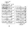
図8は、低い誘電率εb1及び/又は損失正接δb1を有するバッファ層52をチップ42上に備える樹脂封止半導体装置40を形成する方法100を示す概略フローチャートを示している。次に、図5及び8を参照すると、方法100はSTART(開始)102及び第1工程104から始まり、この工程では、チップ42をウェハ82中に、そして/またはウェハ82上に(図8〜10では「IN/ON」と略記する)形成する(図5の段階80−1を参照)。段階80−2に対応する工程106では、ウェハ82(及びチップ42)を、低い誘電率εb1及び/又は損失正接δb1を有する層52で被覆する。バッファ層52の誘電率εb1または損失正接δb1のいずれかが、または両方が、封止樹脂47のそれぞれの該当する誘電率εeまたは損失正接δeよりも小さい限り、利点が得られる。次の工程108では、バッファ層52をマスク層60で被覆する(段階80−3)。工程110では、マスク層60をパターニングして、所望の開口を、ボンディングパッド44上方のバッファ層52に形成する(段階80−4)。工程112では、バッファ層52をボンディングパッド44の上から除去して、バッファ層52がチップ42の残りの部分の上の表面50及び導体、及び配線51を覆ったままの状態とする(段階80−5)。工程114では、バッファ層52を必須ではないが有利となるように硬化させる。図5についての議論に関連して前に述べたように、硬化工程114は工程106の後のどの時点でも有利な形で実行することができるので、方法100において順番に並ぶように配置した工程114の位置は、単に説明を分かり易くするために示しているのであり、この位置に制限するために示しているのではない。図5の段階80−6に示すマスク層60の除去は図8には示されず、省略することができる、または工程112の後のいずれの時点においても実行することができる。工程116では、完成ウェハ82を切断して別々の個々のチップ42とし、そしてこれらの複数のチップを、例えばリードフレームまたは他の支持体に接着し、更にボンディングワイヤまたは他の電気接続線をボンディングパッド44に接続する。この時点で、リードフレーム及びチップに、工程118で行なわれる封止処理を施す状態になり、この場合、マウントし、ワイヤボンディングされ、バッファ層で被覆されたチップを封止樹脂47で封止する(図3〜4参照)。パッケージ構造の特定の種類によって変わるが、次に工程120を行なって、リードフレームをトリミングし、そしてパッケージリードを所望の形状に成形する。このようなトリミング加工及び成形加工は従来から行なわれている。次に、方法100はEND(終了)122に進む。
FIG. 8 shows a schematic flowchart illustrating a
図9は、別の実施形態による、低い誘電率εb1及び/又は損失正接δb1を有するバッファ層52をチップ42上に備える樹脂封止半導体(SC)装置40を形成する方法200を示す概略フローチャートを示している。次に、図6及び9を参照すると、方法200はSTART(開始)202及び第1工程204(段階80’−1)から始まり、そして工程212(段階80’−6)まで進む。方法200の工程204〜212は、図8の方法100の工程104〜112に類似する。従って、工程104〜112についての議論は、ここで参照することにより図9についての議論に組み込まれる。工程214(段階80’−7)では、バッファ層52の外側表面76’,77’を、図6に関連して説明したように処理して、これらの表面をシール層に改質する。方法200の硬化工程216は方法100の硬化工程114に類似し、そして方法200において順番に並べた工程に示す特定の位置に制限されない。バッファ層52−1及びシール層52−2は同時に硬化させることができる、または選択する材料及び使用する処理によって変わる形で個別に硬化させることができる。選択する処理によって変わるが、シール層52−2には、どのような個別の硬化工程も必要とはならない。この技術分野の当業者であれば、バッファ層52−1(及び適宜、バッファ層52−2)を硬化させる最適な順番を、当業者がバッファ層52を形成するために行なった材料選択及び処理選択によって変わる形でどのようにして選択すれば良いかが分かるであろう。方法200の工程218〜220は、方法100の工程116〜120に類似するので、図6に関連する箇所についての議論は、ここで参照することにより図9についての議論に組み込まれる。次に、方法200はEND(終了)224に進む。
FIG. 9 is a schematic illustrating a
図10は、更に別の実施形態による、低い誘電率εb1及び/又は損失正接δb1を有するバッファ層52をチップ42上に備える樹脂封止半導体(SC)装置40を形成する方法300を示す概略フローチャートを示している。次に、図7及び10を参照すると、方法300はSTART(開始)302及び第1工程304(段階80”−1)から始まり、そして工程312(段階80”−6)まで進む。方法300の工程304〜312は、図8の方法100の工程104〜112に類似する。従って、工程104〜112についての議論は、ここで参照することにより図10についての議論に組み込まれる。工程314(段階80”−7)では、バッファ層52−2を、ウェハ全体の上に、かつ少なくとも表面50、ボンディングパッド44、及び導体51の上にほぼコンフォーマルに塗布形成する。工程316(段階80”−8)では、シール層52−2を、例えばフォトレジストから成る第2マスク層70で被覆する。工程318(段階80”−9)では、マスク層70をパターニングして、シール層52−2の内、ボンディングパッド44の中心部分44’の上方の部分74を露出させる。工程320(段階80”−10)では、シール層52−2の部分74をボンディングパッド44の中心部分44’から、シール層52−2に選択される材料によって変わるいずれかの簡便な手段(エッチング、現像、及び溶解など)によって除去する。段階80”−10では、マスク層70のマスク部分が除去されているものとして示されるが、この構成は必須ではない。工程322では、バッファ層52−1及びシール層52−2を硬化させる。方法100,200に関連して述べたように、硬化工程322はプロセスの種々の段階でバッファ層52−1に対して、バッファ層を塗布形成した後のいずれかの時点で、そしてシール層52−2に対して、シール層を塗布形成した後のいずれかの時点において行なうことができる。バッファ層52−1及びシール層52−2は、個別に硬化させる、または一緒に硬化させることができ、そして図10の方法300の硬化工程322が工程320と324との間に位置する構成は、単に説明を分かり易くするために示しているのであり、この構成に制限するために示しているのではない。この技術分野の当業者であれば、方法300を実行している間のこのような硬化工程に適する時点、または順番を、例えば当業者が選択した材料の特定の組み合わせによって変わる形でどのようにして選択すれば良いかが分かるであろう。工程324〜328は、図8の方法100の工程116〜120に類似するので、工程116〜120に関する議論は、ここで参照することにより図10に関する議論に組み込まれる。次に、方法300はEND(終了)330に進む。
FIG. 10 illustrates a
第1の実施形態によれば、半導体装置が提供され、この半導体装置は、支持部材と、一つ以上の電気導体が設けられた外向きチップ表面を有する半導体チップであって、外向きチップ表面が側部表面によって横方向に終端し、かつチップが支持部材の一部分にマウントされる構成の半導体チップと、誘電率εe及び/又は損失正接δeを有し、かつ支持部材及びチップの少なくとも一部分を封止する封止樹脂と、そして封止樹脂の誘電率εe及び損失正接δeよりも小さい誘電率εb1及び/又は損失正接δb1を有し、かつ封止樹脂と外向きチップ表面との間に位置し、更に一つ以上の電気導体の幾つか、または全てを被覆するが側部表面はほとんど被覆しないバッファ層と、を備える。別の実施形態では、バッファ層は約3.0未満の誘電率εb1を有する。更に別の実施形態では、バッファ層は約0.005未満の損失正接δb1を有する。更に別の実施形態では、半導体装置は更に、バッファ層と封止樹脂との間に位置するシール層を備える。更に別の実施形態では、半導体装置は更に、ボンディングパッドを外向きチップ表面に備え、そしてバッファ層は、外向きチップ表面上を、外向きチップ表面上のボンディングパッドの間のほぼ全体に渡って、ボンディングパッドをほとんど被覆することなく延びる。更に別の実施形態では、バッファ層は、ボンディングパッドの間の外向きチップ表面にほぼコンフォーマルに形成される第1の表面と、そしてボンディングパッドに隣接する一つ以上の第2の横向き表面と、を有する。更に別の実施形態では、半導体装置は更に、バッファ層と封止樹脂との間に位置するシール層を、バッファ層の第1及び第2の表面の上に備える。 According to a first embodiment, a semiconductor device is provided, which is a semiconductor chip having an outward chip surface provided with a support member and one or more electrical conductors, the outward chip surface Having a dielectric constant ε e and / or loss tangent δ e, and having at least one of the support member and the chip terminated laterally by the side surface and mounted on a portion of the support member A sealing resin that seals a portion, and a dielectric constant ε b1 and / or a loss tangent δ b1 smaller than the dielectric constant ε e and the loss tangent δ e of the sealing resin, and the sealing resin and the outward chip A buffer layer located between the surfaces and covering some or all of the one or more electrical conductors but hardly covering the side surfaces. In another embodiment, the buffer layer has a dielectric constant ε b1 of less than about 3.0. In yet another embodiment, the buffer layer has a loss tangent δ b1 of less than about 0.005. In yet another embodiment, the semiconductor device further includes a sealing layer positioned between the buffer layer and the sealing resin. In yet another embodiment, the semiconductor device further comprises a bonding pad on the outward chip surface, and the buffer layer is on the outward chip surface over substantially the entire area between the bonding pads on the outward chip surface. , Extending almost without covering the bonding pad. In yet another embodiment, the buffer layer includes a first surface that is substantially conformally formed on the outwardly facing chip surface between the bonding pads, and one or more second lateral surfaces adjacent to the bonding pads. Have. In yet another embodiment, the semiconductor device further comprises a sealing layer located between the buffer layer and the sealing resin on the first and second surfaces of the buffer layer.
第2の実施形態によれば、外部リードを備える半導体装置が提供され、この半導体装置は、導電配線が設けられ、かつ外部リードに接続されるように適合させたボンディングパッドが設けられた主面を有する半導体チップと、第1誘電率及び第1損失正接を有し、かつ半導体チップの一つ以上の面を取り囲む封止樹脂と、第2誘電率及び第2損失正接を有し、かつ封止樹脂と半導体チップの主面との間に位置して、配線の少なくとも或る部分を被覆するが、ボンディングパッドを外部リードに電気的に接続するために使用されるボンディングパッド領域をほとんど被覆することがないバッファ層と、を備え、第2誘電率または第2損失正接の内の少なくとも一つのパラメータが該当する第1誘電率または第1損失正接よりも小さい。別の実施形態によれば、第2誘電率及び第2損失正接は共に、該当する第1誘電率及び第1損失正接よりも小さい。更に別の実施形態によれば、半導体装置は更に、バッファ層と封止樹脂との間に位置するシール層を備える。更に別の実施形態によれば、シール層は防湿気密層である。更に別の実施形態によれば、第2誘電率は約2.8未満である。更に別の実施形態によれば、第2損失正接は約0.005未満である。 According to the second embodiment, a semiconductor device including an external lead is provided, and the semiconductor device is provided with a conductive wiring and a main surface provided with a bonding pad adapted to be connected to the external lead. A semiconductor chip having a first dielectric constant and a first loss tangent and enclosing one or more surfaces of the semiconductor chip; a second dielectric constant and a second loss tangent; Located between the stop resin and the main surface of the semiconductor chip, covers at least some portion of the wiring, but covers most of the bonding pad area used to electrically connect the bonding pads to the external leads. And at least one parameter of the second dielectric constant or the second loss tangent is smaller than the corresponding first dielectric constant or first loss tangent. According to another embodiment, both the second dielectric constant and the second loss tangent are smaller than the corresponding first dielectric constant and first loss tangent. According to still another embodiment, the semiconductor device further includes a seal layer positioned between the buffer layer and the sealing resin. According to yet another embodiment, the sealing layer is a moisture-proof and airtight layer. According to yet another embodiment, the second dielectric constant is less than about 2.8. According to yet another embodiment, the second loss tangent is less than about 0.005.
第3の実施形態によれば、半導体チップを配設する方法が提供され、この方法は、導電配線及びボンディングパッドが設けられた主面を有するチップを含むSCウェハを設ける工程と、チップの主面の或る部分または全ての部分を、チップを封止する樹脂に使用される材料の誘電率及び損失正接の一方または他方よりも小さい誘電率εbl及び/又は損失正接δblをそれぞれ有するバッファ層で被覆する工程と、そしてバッファ層をパターニングして、チップを外部リードに接続するために使用されるボンディングパッド上の領域をほとんど露出させるが、バッファ層を導電配線の少なくとも或る部分の上に残す工程と、を含む。更に別の実施形態によれば、本方法は更に、ボンディングパッドの露出領域を外部リードに接続する工程を含む。更に別の実施形態によれば、本方法は更に、チップ及び外部リードのインナーリード部分を、誘電率εe及び損失正接δeを有する封止樹脂で取り囲む工程を含み、誘電率εeが誘電率εblよりも大きいか、または損失正接δeが損失正接δblよりも大きいかのいずれかであり、そしてバッファ層によって導電配線の少なくとも或る部分を封止樹脂から分離する。更に別の実施形態によれば、誘電率εeは誘電率εblよりも大きく、かつ損失正接δeは損失正接δblをよりも大きい。更に別の実施形態によれば、本方法は更に、パターニングする工程の後に、シール層をバッファ層の外側表面上に形成する工程を含む。更に別の実施形態によれば、本方法は更に、形成する工程の後に、シール層をパターニングして、チップを外部リードに接続するために使用されるボンディングパッド上の領域をほとんど露出させるが、シール層を、導電配線を被覆するバッファ層の少なくとも一部分のほぼ全体を覆うように残す工程を含む。更に別の実施形態によれば、本方法は更に、取り囲む工程の前に、シール層をバッファ層の外側表面上に形成する工程を含む。 According to the third embodiment, a method for disposing a semiconductor chip is provided, which includes providing an SC wafer including a chip having a main surface provided with conductive wiring and bonding pads; Buffers having a dielectric constant ε bl and / or a loss tangent δ bl smaller than one or the other of the dielectric constant and loss tangent of the material used for the resin encapsulating the chip, some or all of the surface Coating with a layer, and patterning the buffer layer to expose most of the area on the bonding pad used to connect the chip to external leads, but the buffer layer is over at least some portion of the conductive traces. And the process of leaving. According to yet another embodiment, the method further includes connecting the exposed area of the bonding pad to an external lead. According to yet another embodiment, the method further includes the step of enclosing the inner lead portion of the chip and external leads with a sealing resin having a dielectric constant ε e and a loss tangent δ e , where the dielectric constant ε e is a dielectric. Either the ratio ε bl or the loss tangent δ e is greater than the loss tangent δ bl , and at least some portion of the conductive wiring is separated from the sealing resin by the buffer layer. According to yet another embodiment, the dielectric constant ε e is greater than the dielectric constant ε bl and the loss tangent δ e is greater than the loss tangent δ bl . According to yet another embodiment, the method further includes forming a sealing layer on the outer surface of the buffer layer after the patterning step. According to yet another embodiment, the method further patterns the sealing layer after the forming step to expose most of the area on the bonding pad used to connect the chip to the external leads, Leaving the seal layer so as to cover substantially the entire at least part of the buffer layer covering the conductive wiring. According to yet another embodiment, the method further includes forming a sealing layer on the outer surface of the buffer layer prior to the enclosing step.
少なくとも一つの例示としての実施形態をこれまでの詳細な記述に示してきたが、非常に多くの変形例が在ることを理解されたい。例えば、低誘電体及び低損失正接を有する非常に多くの種類の材料をバッファ層52に使用することができる。この技術分野の当業者であれば、本明細書における事例が示唆する原理がこのような変形例にも当てはまることが理解できるであろう。従って、これまでの詳細な記述は、この技術分野の当業者にとって、例示としての実施形態または例示としての複数の実施形態を実施するための有用な指針となる。種々の変更を構成要素の機能及び構成に関して、添付の請求項及び請求項の法的な均等物に示される本発明の技術範囲から逸脱しない限り加えることができることを理解されたい。
While at least one exemplary embodiment has been presented in the foregoing detailed description, it should be appreciated that a vast number of variations exist. For example, numerous types of materials with low dielectrics and low loss tangents can be used for the
Claims (20)
一つ以上の電気導体が設けられ、及び、外側に指向しているチップ表面を有した半導体チップと、前記半導体チップの前記チップ表面は水平方向において側面によって終端し、かつチップが前記支持部材の一部に載置されることと、
誘電率εe及び損失正接δeを有し、かつ支持部材及びチップの少なくとも一部分を封止する封止樹脂と、
封止樹脂の誘電率εe及び損失正接δeよりも小さい誘電率εb1及び損失正接δb1のうちの少なくとも1つを有し、かつ封止樹脂とチップ表面との間に設けられて1つ以上の電気導体の少なくともいくつかを被覆する間に前記側面の大部分は被覆することがないバッファ層と、を備える半導体装置。 A support member;
A semiconductor chip provided with one or more electrical conductors and having a chip surface directed outward; the chip surface of the semiconductor chip is terminated by a side surface in the horizontal direction; and the chip is of the support member Being partly placed,
A sealing resin having a dielectric constant ε e and a loss tangent δ e and sealing at least a part of the support member and the chip;
It has at least one of a dielectric constant ε b1 and a loss tangent δ b1 smaller than the dielectric constant ε e and the loss tangent δ e of the sealing resin, and is 1 provided between the sealing resin and the chip surface. And a buffer layer that does not cover most of the side surface while covering at least some of the one or more electrical conductors.
導電配線が設けられ、かつ外部リードに接続されるように適合させたボンディングパッドが設けられた主面を有する半導体チップと、
第1誘電率及び第1損失正接を有し、かつ半導体チップの一つ以上の面を取り囲む封止樹脂と、
第2誘電率及び第2損失正接を有し、かつ封止樹脂と半導体チップの主面との間に位置して、配線の少なくとも或る部分を被覆するが、ボンディングパッドを外部リードに電気的に接続するために使用されるボンディングパッド領域の大部分を被覆することがないバッファ層とを備え、
第2誘電率または第2損失正接の内の少なくとも一つのパラメータは、該当する第1誘電率または第1損失正接よりも小さい、樹脂封止半導体装置。 In a resin-encapsulated semiconductor device having external leads,
A semiconductor chip having a main surface provided with a conductive pad and a bonding pad adapted to be connected to an external lead;
A sealing resin having a first dielectric constant and a first loss tangent and surrounding one or more surfaces of the semiconductor chip;
It has a second dielectric constant and a second loss tangent, and is located between the sealing resin and the main surface of the semiconductor chip and covers at least a part of the wiring, but electrically connects the bonding pad to the external lead A buffer layer that does not cover most of the bonding pad area used to connect to
The resin-encapsulated semiconductor device, wherein at least one parameter of the second dielectric constant or the second loss tangent is smaller than the corresponding first dielectric constant or first loss tangent.
導電配線及びボンディングパッドが設けられた主面を有するチップを含む半導体チップウェハを設ける工程と、
誘電率εbl及び損失正接δblの少なくとも1つがチップを封止する樹脂に使用される材料の誘電率及び損失正接よりも小さいバッファ層でチップの主面の少なくとも一部を被覆する工程と、
バッファ層をパターニングして、チップを外部リードに接続するために使用されるボンディングパッド上の領域の大部分を露出させる間に、バッファ層を導電配線の少なくとも一部の上に残す工程とを備える方法。 In a method of arranging a semiconductor chip,
Providing a semiconductor chip wafer including a chip having a main surface provided with conductive wiring and bonding pads;
Coating at least a portion of the main surface of the chip with a buffer layer in which at least one of dielectric constant ε bl and loss tangent δ bl is smaller than the dielectric constant and loss tangent of the material used for the resin encapsulating the chip;
Patterning the buffer layer to leave the buffer layer over at least a portion of the conductive wiring while exposing most of the area on the bonding pad used to connect the chip to the external leads. Method.
Applications Claiming Priority (2)
| Application Number | Priority Date | Filing Date | Title |
|---|---|---|---|
| US11/257,822 US7432133B2 (en) | 2005-10-24 | 2005-10-24 | Plastic packaged device with die interface layer |
| PCT/US2006/040871 WO2007050422A2 (en) | 2005-10-24 | 2006-10-18 | Plastic packaged device with die interface layer |
Publications (2)
| Publication Number | Publication Date |
|---|---|
| JP2009513030A true JP2009513030A (en) | 2009-03-26 |
| JP2009513030A5 JP2009513030A5 (en) | 2009-12-03 |
Family
ID=37968398
Family Applications (1)
| Application Number | Title | Priority Date | Filing Date |
|---|---|---|---|
| JP2008537793A Pending JP2009513030A (en) | 2005-10-24 | 2006-10-18 | Resin package semiconductor device having interface layer |
Country Status (5)
| Country | Link |
|---|---|
| US (1) | US7432133B2 (en) |
| JP (1) | JP2009513030A (en) |
| CN (1) | CN101517718B (en) |
| TW (1) | TWI470747B (en) |
| WO (1) | WO2007050422A2 (en) |
Families Citing this family (16)
| Publication number | Priority date | Publication date | Assignee | Title |
|---|---|---|---|---|
| AU2005304912A1 (en) | 2004-11-04 | 2006-05-18 | Smith & Nephew, Inc. | Cycle and load measurement device |
| WO2007025191A1 (en) | 2005-08-23 | 2007-03-01 | Smith & Nephew, Inc. | Telemetric orthopaedic implant |
| JP4773307B2 (en) * | 2006-09-15 | 2011-09-14 | Okiセミコンダクタ株式会社 | Manufacturing method of semiconductor device |
| EP2114247B1 (en) | 2007-02-23 | 2013-10-30 | Smith & Nephew, Inc. | Processing sensed accelerometer data for determination of bone healing |
| CN107115591A (en) * | 2007-09-06 | 2017-09-01 | 史密夫和内修有限公司 | System and method for being communicated with remote measurement implant |
| EP2248274A4 (en) * | 2008-02-01 | 2015-10-07 | Smith & Nephew Inc | System and method for communicating with an implant |
| US8704124B2 (en) | 2009-01-29 | 2014-04-22 | Smith & Nephew, Inc. | Low temperature encapsulate welding |
| US8866708B2 (en) * | 2011-01-21 | 2014-10-21 | Peter Sui Lun Fong | Light emitting diode switch device and array |
| US9190393B1 (en) | 2013-09-10 | 2015-11-17 | Delta Electronics, Inc. | Low parasitic capacitance semiconductor device package |
| US10224260B2 (en) * | 2013-11-26 | 2019-03-05 | Infineon Technologies Ag | Semiconductor package with air gap |
| JP2015231027A (en) * | 2014-06-06 | 2015-12-21 | 住友電気工業株式会社 | Semiconductor device |
| US10672703B2 (en) | 2018-09-26 | 2020-06-02 | Nxp Usa, Inc. | Transistor with shield structure, packaged device, and method of fabrication |
| CN109273418A (en) * | 2018-11-08 | 2019-01-25 | 中国科学院苏州纳米技术与纳米仿生研究所南昌研究院 | A kind of chip-packaging structure and method |
| US11248769B2 (en) | 2019-04-10 | 2022-02-15 | Peter Sui Lun Fong | Optic for touch-sensitive light emitting diode switch |
| US11728305B2 (en) | 2021-05-11 | 2023-08-15 | Sandisk Technologies Llc | Capacitor structure including bonding pads as electrodes and methods of forming the same |
| CN114678298B (en) * | 2022-03-14 | 2022-09-09 | 珠海市众知科技有限公司 | Integrated circuit block pin packaging hardware |
Citations (2)
| Publication number | Priority date | Publication date | Assignee | Title |
|---|---|---|---|---|
| JPH0794642A (en) * | 1993-07-27 | 1995-04-07 | Toshiba Corp | Semiconductor device |
| JPH1065067A (en) * | 1996-08-22 | 1998-03-06 | Toshiba Corp | Semiconductor device and its manufacture |
Family Cites Families (13)
| Publication number | Priority date | Publication date | Assignee | Title |
|---|---|---|---|---|
| JP2906282B2 (en) * | 1990-09-20 | 1999-06-14 | 富士通株式会社 | Glass-ceramic green sheet, multilayer substrate, and manufacturing method thereof |
| JPH04314394A (en) * | 1991-04-12 | 1992-11-05 | Fujitsu Ltd | Glass ceramic circuit board and manufacture thereof |
| US5598034A (en) * | 1992-07-22 | 1997-01-28 | Vlsi Packaging Corporation | Plastic packaging of microelectronic circuit devices |
| KR100280762B1 (en) * | 1992-11-03 | 2001-03-02 | 비센트 비.인그라시아 | Thermally Reinforced Semiconductor Devices Having Exposed Backsides and Methods of Manufacturing the Same |
| US5578860A (en) * | 1995-05-01 | 1996-11-26 | Motorola, Inc. | Monolithic high frequency integrated circuit structure having a grounded source configuration |
| JP3516592B2 (en) * | 1998-08-18 | 2004-04-05 | 沖電気工業株式会社 | Semiconductor device and manufacturing method thereof |
| US6001673A (en) * | 1999-02-11 | 1999-12-14 | Ericsson Inc. | Methods for packaging integrated circuit devices including cavities adjacent active regions |
| KR100298827B1 (en) * | 1999-07-09 | 2001-11-01 | 윤종용 | Method For Manufacturing Wafer Level Chip Scale Packages Using Redistribution Substrate |
| US6509415B1 (en) * | 2000-04-07 | 2003-01-21 | Honeywell International Inc. | Low dielectric constant organic dielectrics based on cage-like structures |
| US6627669B2 (en) * | 2000-06-06 | 2003-09-30 | Honeywell International Inc. | Low dielectric materials and methods of producing same |
| US6423811B1 (en) * | 2000-07-19 | 2002-07-23 | Honeywell International Inc. | Low dielectric constant materials with polymeric networks |
| EP1215724B1 (en) * | 2000-11-20 | 2012-10-31 | Texas Instruments Incorporated | Wire bonded semiconductor device with low capacitance coupling |
| US6744117B2 (en) * | 2002-02-28 | 2004-06-01 | Motorola, Inc. | High frequency semiconductor device and method of manufacture |
-
2005
- 2005-10-24 US US11/257,822 patent/US7432133B2/en active Active
-
2006
- 2006-10-18 WO PCT/US2006/040871 patent/WO2007050422A2/en active Application Filing
- 2006-10-18 JP JP2008537793A patent/JP2009513030A/en active Pending
- 2006-10-18 CN CN2006800397984A patent/CN101517718B/en active Active
- 2006-10-23 TW TW95139048A patent/TWI470747B/en active
Patent Citations (2)
| Publication number | Priority date | Publication date | Assignee | Title |
|---|---|---|---|---|
| JPH0794642A (en) * | 1993-07-27 | 1995-04-07 | Toshiba Corp | Semiconductor device |
| JPH1065067A (en) * | 1996-08-22 | 1998-03-06 | Toshiba Corp | Semiconductor device and its manufacture |
Also Published As
| Publication number | Publication date |
|---|---|
| US7432133B2 (en) | 2008-10-07 |
| WO2007050422A3 (en) | 2009-05-14 |
| CN101517718A (en) | 2009-08-26 |
| WO2007050422A2 (en) | 2007-05-03 |
| TWI470747B (en) | 2015-01-21 |
| US20070090543A1 (en) | 2007-04-26 |
| TW200731476A (en) | 2007-08-16 |
| CN101517718B (en) | 2011-01-26 |
Similar Documents
| Publication | Publication Date | Title |
|---|---|---|
| JP2009513030A (en) | Resin package semiconductor device having interface layer | |
| KR101296701B1 (en) | Semiconductor device with reduced package cross-talk and loss | |
| KR101548739B1 (en) | semiconductor device package | |
| US8084300B1 (en) | RF shielding for a singulated laminate semiconductor device package | |
| US20050242425A1 (en) | Semiconductor device with a protected active die region and method therefor | |
| US20080014678A1 (en) | System and method of attenuating electromagnetic interference with a grounded top film | |
| US11251138B2 (en) | Through wafer trench isolation between transistors in an integrated circuit | |
| KR20030046940A (en) | Method of packaging surface acoustic wave device | |
| JP5721742B2 (en) | Electrical coupling of wafer structures | |
| JP2009513029A (en) | Semiconductor device with improved sealing | |
| KR100826393B1 (en) | Wafer level device package with sealing line having electroconductive pattern and method of packaging the same | |
| TWI378515B (en) | Method of fabricating quad flat non-leaded package | |
| KR20080101256A (en) | Wafer level package and method of wafer level packaging | |
| JP5651057B2 (en) | Semiconductor device and manufacturing method of semiconductor device | |
| TWI452667B (en) | Semiconductor package device with cavity structure and the packaging method thereof | |
| JP2021535606A (en) | Wafer level system packaging method and packaging structure | |
| TWI772219B (en) | Chip packaging structure with electromagnetic shielding and forming method thereof | |
| KR20090016836A (en) | A surface acoustic wave package and fabrication method thereof | |
| KR100545216B1 (en) | Method for forming the pad of semiconductor device | |
| KR100998040B1 (en) | Substrate for semiconductor package, semiconductor package having such, and method for manufacturing the said semiconductor package | |
| CN102148172A (en) | Semiconductor process, semiconductor component and package structure with semiconductor component | |
| KR100878409B1 (en) | Wafer level device package and method of packaging the same | |
| US10134660B2 (en) | Semiconductor device having corrugated leads and method for forming | |
| CN105621344B (en) | MEMS air-tight packagings structure and packaging method | |
| US9741646B2 (en) | Package substrate and its fabrication method |
Legal Events
| Date | Code | Title | Description |
|---|---|---|---|
| A521 | Request for written amendment filed |
Free format text: JAPANESE INTERMEDIATE CODE: A523 Effective date: 20091019 |
|
| A621 | Written request for application examination |
Free format text: JAPANESE INTERMEDIATE CODE: A621 Effective date: 20091019 |
|
| A977 | Report on retrieval |
Free format text: JAPANESE INTERMEDIATE CODE: A971007 Effective date: 20100624 |
|
| A131 | Notification of reasons for refusal |
Free format text: JAPANESE INTERMEDIATE CODE: A131 Effective date: 20110405 |
|
| A521 | Request for written amendment filed |
Free format text: JAPANESE INTERMEDIATE CODE: A523 Effective date: 20110705 |
|
| A02 | Decision of refusal |
Free format text: JAPANESE INTERMEDIATE CODE: A02 Effective date: 20111206 |