JP2009509643A - Handheld device for delivering an agent to a biological interface - Google Patents
Handheld device for delivering an agent to a biological interface Download PDFInfo
- Publication number
- JP2009509643A JP2009509643A JP2008533458A JP2008533458A JP2009509643A JP 2009509643 A JP2009509643 A JP 2009509643A JP 2008533458 A JP2008533458 A JP 2008533458A JP 2008533458 A JP2008533458 A JP 2008533458A JP 2009509643 A JP2009509643 A JP 2009509643A
- Authority
- JP
- Japan
- Prior art keywords
- agent
- working electrode
- living body
- electrode structure
- active substance
- Prior art date
- Legal status (The legal status is an assumption and is not a legal conclusion. Google has not performed a legal analysis and makes no representation as to the accuracy of the status listed.)
- Pending
Links
- 239000003795 chemical substances by application Substances 0.000 claims description 199
- 239000012528 membrane Substances 0.000 claims description 140
- 150000002500 ions Chemical class 0.000 claims description 103
- 239000013543 active substance Substances 0.000 claims description 93
- 239000000523 sample Substances 0.000 claims description 83
- 239000003792 electrolyte Substances 0.000 claims description 52
- 239000003014 ion exchange membrane Substances 0.000 claims description 28
- 150000001875 compounds Chemical class 0.000 claims description 17
- 229910001631 strontium chloride Inorganic materials 0.000 claims description 13
- AHBGXTDRMVNFER-UHFFFAOYSA-L strontium dichloride Chemical compound [Cl-].[Cl-].[Sr+2] AHBGXTDRMVNFER-UHFFFAOYSA-L 0.000 claims description 13
- KRHYYFGTRYWZRS-UHFFFAOYSA-M Fluoride anion Chemical compound [F-] KRHYYFGTRYWZRS-UHFFFAOYSA-M 0.000 claims description 9
- 229910052712 strontium Inorganic materials 0.000 claims description 7
- CIOAGBVUUVVLOB-UHFFFAOYSA-N strontium atom Chemical compound [Sr] CIOAGBVUUVVLOB-UHFFFAOYSA-N 0.000 claims description 7
- 239000000126 substance Substances 0.000 claims description 7
- 229910052709 silver Inorganic materials 0.000 claims description 5
- 239000004332 silver Substances 0.000 claims description 5
- 230000004044 response Effects 0.000 claims description 4
- HKZLPVFGJNLROG-UHFFFAOYSA-M silver monochloride Chemical compound [Cl-].[Ag+] HKZLPVFGJNLROG-UHFFFAOYSA-M 0.000 claims description 3
- 229910021607 Silver chloride Inorganic materials 0.000 claims description 2
- 230000009471 action Effects 0.000 claims description 2
- 210000004379 membrane Anatomy 0.000 description 117
- 239000000463 material Substances 0.000 description 16
- 210000000515 tooth Anatomy 0.000 description 15
- 239000007787 solid Substances 0.000 description 13
- 239000000499 gel Substances 0.000 description 12
- 239000000203 mixture Substances 0.000 description 12
- 238000005342 ion exchange Methods 0.000 description 11
- 239000000872 buffer Substances 0.000 description 10
- 239000003814 drug Substances 0.000 description 10
- 239000003011 anion exchange membrane Substances 0.000 description 9
- 238000005341 cation exchange Methods 0.000 description 8
- 239000000017 hydrogel Substances 0.000 description 8
- 210000003491 skin Anatomy 0.000 description 8
- 210000001519 tissue Anatomy 0.000 description 8
- 150000001768 cations Chemical class 0.000 description 6
- 238000004519 manufacturing process Methods 0.000 description 5
- 238000000034 method Methods 0.000 description 5
- 229940124597 therapeutic agent Drugs 0.000 description 5
- 238000012546 transfer Methods 0.000 description 5
- 238000010586 diagram Methods 0.000 description 4
- 229940079593 drug Drugs 0.000 description 4
- 239000012530 fluid Substances 0.000 description 4
- 239000000446 fuel Substances 0.000 description 4
- 239000007788 liquid Substances 0.000 description 4
- 230000005012 migration Effects 0.000 description 4
- 238000013508 migration Methods 0.000 description 4
- 239000012778 molding material Substances 0.000 description 4
- 210000000214 mouth Anatomy 0.000 description 4
- 239000011148 porous material Substances 0.000 description 4
- 230000000717 retained effect Effects 0.000 description 4
- 239000002904 solvent Substances 0.000 description 4
- 229920000049 Carbon (fiber) Polymers 0.000 description 3
- YCKRFDGAMUMZLT-UHFFFAOYSA-N Fluorine atom Chemical compound [F] YCKRFDGAMUMZLT-UHFFFAOYSA-N 0.000 description 3
- 125000000129 anionic group Chemical group 0.000 description 3
- 150000001450 anions Chemical class 0.000 description 3
- 239000004917 carbon fiber Substances 0.000 description 3
- 229910052731 fluorine Inorganic materials 0.000 description 3
- 239000011737 fluorine Substances 0.000 description 3
- 230000007246 mechanism Effects 0.000 description 3
- VNWKTOKETHGBQD-UHFFFAOYSA-N methane Chemical compound C VNWKTOKETHGBQD-UHFFFAOYSA-N 0.000 description 3
- 210000004400 mucous membrane Anatomy 0.000 description 3
- 102000039446 nucleic acids Human genes 0.000 description 3
- 108020004707 nucleic acids Proteins 0.000 description 3
- 150000007523 nucleic acids Chemical class 0.000 description 3
- 230000008447 perception Effects 0.000 description 3
- 231100000572 poisoning Toxicity 0.000 description 3
- 230000000607 poisoning effect Effects 0.000 description 3
- 108090000765 processed proteins & peptides Proteins 0.000 description 3
- 102000004196 processed proteins & peptides Human genes 0.000 description 3
- 108090000623 proteins and genes Proteins 0.000 description 3
- 102000004169 proteins and genes Human genes 0.000 description 3
- 239000000243 solution Substances 0.000 description 3
- 150000003438 strontium compounds Chemical class 0.000 description 3
- -1 AM-3 Chemical compound 0.000 description 2
- 229910000497 Amalgam Inorganic materials 0.000 description 2
- OKTJSMMVPCPJKN-UHFFFAOYSA-N Carbon Chemical compound [C] OKTJSMMVPCPJKN-UHFFFAOYSA-N 0.000 description 2
- NNJVILVZKWQKPM-UHFFFAOYSA-N Lidocaine Chemical compound CCN(CC)CC(=O)NC1=C(C)C=CC=C1C NNJVILVZKWQKPM-UHFFFAOYSA-N 0.000 description 2
- VYPSYNLAJGMNEJ-UHFFFAOYSA-N Silicium dioxide Chemical compound O=[Si]=O VYPSYNLAJGMNEJ-UHFFFAOYSA-N 0.000 description 2
- BQCADISMDOOEFD-UHFFFAOYSA-N Silver Chemical compound [Ag] BQCADISMDOOEFD-UHFFFAOYSA-N 0.000 description 2
- FAPWRFPIFSIZLT-UHFFFAOYSA-M Sodium chloride Chemical compound [Na+].[Cl-] FAPWRFPIFSIZLT-UHFFFAOYSA-M 0.000 description 2
- 239000011149 active material Substances 0.000 description 2
- 238000003491 array Methods 0.000 description 2
- 230000004888 barrier function Effects 0.000 description 2
- 230000008901 benefit Effects 0.000 description 2
- 230000015572 biosynthetic process Effects 0.000 description 2
- 229910052799 carbon Inorganic materials 0.000 description 2
- 125000002091 cationic group Chemical group 0.000 description 2
- 238000004891 communication Methods 0.000 description 2
- 210000002615 epidermis Anatomy 0.000 description 2
- 210000003811 finger Anatomy 0.000 description 2
- 229910052739 hydrogen Inorganic materials 0.000 description 2
- 239000001257 hydrogen Substances 0.000 description 2
- 238000002347 injection Methods 0.000 description 2
- 239000007924 injection Substances 0.000 description 2
- 229960004194 lidocaine Drugs 0.000 description 2
- 230000014759 maintenance of location Effects 0.000 description 2
- 239000011159 matrix material Substances 0.000 description 2
- 238000012986 modification Methods 0.000 description 2
- 230000004048 modification Effects 0.000 description 2
- 239000012466 permeate Substances 0.000 description 2
- 229920000867 polyelectrolyte Polymers 0.000 description 2
- 125000006850 spacer group Chemical group 0.000 description 2
- 230000000638 stimulation Effects 0.000 description 2
- XLYOFNOQVPJJNP-UHFFFAOYSA-N water Substances O XLYOFNOQVPJJNP-UHFFFAOYSA-N 0.000 description 2
- 101000767534 Arabidopsis thaliana Chorismate mutase 2 Proteins 0.000 description 1
- 229920013669 Clearsite Polymers 0.000 description 1
- UFHFLCQGNIYNRP-UHFFFAOYSA-N Hydrogen Chemical compound [H][H] UFHFLCQGNIYNRP-UHFFFAOYSA-N 0.000 description 1
- 101000986989 Naja kaouthia Acidic phospholipase A2 CM-II Proteins 0.000 description 1
- 239000004820 Pressure-sensitive adhesive Substances 0.000 description 1
- 108010067520 RADA16-I Proteins 0.000 description 1
- 229920002125 Sokalan® Polymers 0.000 description 1
- SMEGJBVQLJJKKX-HOTMZDKISA-N [(2R,3S,4S,5R,6R)-5-acetyloxy-3,4,6-trihydroxyoxan-2-yl]methyl acetate Chemical compound CC(=O)OC[C@@H]1[C@H]([C@@H]([C@H]([C@@H](O1)O)OC(=O)C)O)O SMEGJBVQLJJKKX-HOTMZDKISA-N 0.000 description 1
- 238000009825 accumulation Methods 0.000 description 1
- 239000002253 acid Substances 0.000 description 1
- 150000007513 acids Chemical class 0.000 description 1
- NIXOWILDQLNWCW-UHFFFAOYSA-N acrylic acid group Chemical group C(C=C)(=O)O NIXOWILDQLNWCW-UHFFFAOYSA-N 0.000 description 1
- 239000004480 active ingredient Substances 0.000 description 1
- 230000001154 acute effect Effects 0.000 description 1
- 239000000853 adhesive Substances 0.000 description 1
- 230000001070 adhesive effect Effects 0.000 description 1
- 230000003444 anaesthetic effect Effects 0.000 description 1
- 238000005349 anion exchange Methods 0.000 description 1
- 239000004621 biodegradable polymer Substances 0.000 description 1
- 229920002988 biodegradable polymer Polymers 0.000 description 1
- 230000000903 blocking effect Effects 0.000 description 1
- 210000000988 bone and bone Anatomy 0.000 description 1
- 239000003010 cation ion exchange membrane Substances 0.000 description 1
- 239000011797 cavity material Substances 0.000 description 1
- 239000000919 ceramic Substances 0.000 description 1
- 239000011248 coating agent Substances 0.000 description 1
- 238000000576 coating method Methods 0.000 description 1
- 210000003298 dental enamel Anatomy 0.000 description 1
- 239000003975 dentin desensitizing agent Substances 0.000 description 1
- 239000000645 desinfectant Substances 0.000 description 1
- 238000009792 diffusion process Methods 0.000 description 1
- MSJMDZAOKORVFC-SEPHDYHBSA-L disodium fumarate Chemical compound [Na+].[Na+].[O-]C(=O)\C=C\C([O-])=O MSJMDZAOKORVFC-SEPHDYHBSA-L 0.000 description 1
- 238000012377 drug delivery Methods 0.000 description 1
- 238000005868 electrolysis reaction Methods 0.000 description 1
- 238000005370 electroosmosis Methods 0.000 description 1
- 230000007613 environmental effect Effects 0.000 description 1
- 238000005530 etching Methods 0.000 description 1
- 230000008020 evaporation Effects 0.000 description 1
- 238000001704 evaporation Methods 0.000 description 1
- 239000007789 gas Substances 0.000 description 1
- 229910001385 heavy metal Inorganic materials 0.000 description 1
- 150000004677 hydrates Chemical class 0.000 description 1
- 230000036571 hydration Effects 0.000 description 1
- 238000006703 hydration reaction Methods 0.000 description 1
- 230000007062 hydrolysis Effects 0.000 description 1
- 238000006460 hydrolysis reaction Methods 0.000 description 1
- 238000003780 insertion Methods 0.000 description 1
- 230000037431 insertion Effects 0.000 description 1
- 230000007794 irritation Effects 0.000 description 1
- 150000002605 large molecules Chemical class 0.000 description 1
- 229910052751 metal Inorganic materials 0.000 description 1
- 239000002184 metal Substances 0.000 description 1
- 150000002739 metals Chemical class 0.000 description 1
- 239000012982 microporous membrane Substances 0.000 description 1
- 239000002991 molded plastic Substances 0.000 description 1
- 210000003097 mucus Anatomy 0.000 description 1
- 210000005036 nerve Anatomy 0.000 description 1
- 230000037361 pathway Effects 0.000 description 1
- 239000004584 polyacrylic acid Substances 0.000 description 1
- 229920000642 polymer Polymers 0.000 description 1
- 229920001184 polypeptide Polymers 0.000 description 1
- 230000008569 process Effects 0.000 description 1
- 239000000047 product Substances 0.000 description 1
- 150000003839 salts Chemical class 0.000 description 1
- 239000012047 saturated solution Substances 0.000 description 1
- 239000010703 silicon Substances 0.000 description 1
- 229910052710 silicon Inorganic materials 0.000 description 1
- 235000012239 silicon dioxide Nutrition 0.000 description 1
- 239000000377 silicon dioxide Substances 0.000 description 1
- 239000011734 sodium Substances 0.000 description 1
- 239000011780 sodium chloride Substances 0.000 description 1
- 235000019294 sodium fumarate Nutrition 0.000 description 1
- 229910001415 sodium ion Inorganic materials 0.000 description 1
- 238000005507 spraying Methods 0.000 description 1
- 230000001954 sterilising effect Effects 0.000 description 1
- 238000004659 sterilization and disinfection Methods 0.000 description 1
- 238000006467 substitution reaction Methods 0.000 description 1
- 239000000758 substrate Substances 0.000 description 1
- 229940126585 therapeutic drug Drugs 0.000 description 1
- 210000003813 thumb Anatomy 0.000 description 1
- 239000000606 toothpaste Substances 0.000 description 1
- 230000001988 toxicity Effects 0.000 description 1
- 231100000419 toxicity Toxicity 0.000 description 1
- 230000007704 transition Effects 0.000 description 1
- 238000007740 vapor deposition Methods 0.000 description 1
Images


Classifications
-
- A—HUMAN NECESSITIES
- A61—MEDICAL OR VETERINARY SCIENCE; HYGIENE
- A61N—ELECTROTHERAPY; MAGNETOTHERAPY; RADIATION THERAPY; ULTRASOUND THERAPY
- A61N1/00—Electrotherapy; Circuits therefor
- A61N1/02—Details
- A61N1/04—Electrodes
- A61N1/0404—Electrodes for external use
- A61N1/0408—Use-related aspects
- A61N1/0428—Specially adapted for iontophoresis, e.g. AC, DC or including drug reservoirs
- A61N1/0448—Drug reservoir
-
- A—HUMAN NECESSITIES
- A61—MEDICAL OR VETERINARY SCIENCE; HYGIENE
- A61N—ELECTROTHERAPY; MAGNETOTHERAPY; RADIATION THERAPY; ULTRASOUND THERAPY
- A61N1/00—Electrotherapy; Circuits therefor
- A61N1/18—Applying electric currents by contact electrodes
- A61N1/20—Applying electric currents by contact electrodes continuous direct currents
- A61N1/30—Apparatus for iontophoresis, i.e. transfer of media in ionic state by an electromotoric force into the body, or cataphoresis
-
- A—HUMAN NECESSITIES
- A61—MEDICAL OR VETERINARY SCIENCE; HYGIENE
- A61N—ELECTROTHERAPY; MAGNETOTHERAPY; RADIATION THERAPY; ULTRASOUND THERAPY
- A61N1/00—Electrotherapy; Circuits therefor
- A61N1/02—Details
- A61N1/04—Electrodes
- A61N1/0404—Electrodes for external use
- A61N1/0408—Use-related aspects
- A61N1/0428—Specially adapted for iontophoresis, e.g. AC, DC or including drug reservoirs
- A61N1/0444—Membrane
-
- A—HUMAN NECESSITIES
- A61—MEDICAL OR VETERINARY SCIENCE; HYGIENE
- A61N—ELECTROTHERAPY; MAGNETOTHERAPY; RADIATION THERAPY; ULTRASOUND THERAPY
- A61N1/00—Electrotherapy; Circuits therefor
- A61N1/02—Details
- A61N1/04—Electrodes
- A61N1/0404—Electrodes for external use
- A61N1/0408—Use-related aspects
- A61N1/0428—Specially adapted for iontophoresis, e.g. AC, DC or including drug reservoirs
- A61N1/0432—Anode and cathode
- A61N1/0436—Material of the electrode
Abstract
生体に作用物質を送達する装置は、電源から生体を通した電気経路を完成させるための、生体の第1の部分を提供するように把持されるように構成されるハンドル形部分と、ハンドル形部分から延びて生体の第2の部分に又はそれに近接して配置されるように構成されるプローブ形の部分とを含む。本装置はイオントフォレーシスを用いることができる。本装置は、従来の歯ブラシ又は電気歯ブラシの形状に似た構成にすることができる。
【選択図】 図1An apparatus for delivering an agent to a living body includes a handle-shaped portion configured to be gripped to provide a first portion of the living body for completing an electrical path through the living body from a power source; A probe-shaped portion extending from the portion and configured to be positioned at or proximate to the second portion of the living body. This apparatus can use iontophoresis. The device can be configured to resemble the shape of a conventional toothbrush or electric toothbrush.
[Selection] Figure 1
Description
本開示は一般的に、イオントフォレーシスの分野に、さらに特定的には生体界面、例えば皮膚、粘膜又は歯への治療薬又は薬剤等の活性物質の送達に関する。 The present disclosure relates generally to the field of iontophoresis, and more particularly to the delivery of active agents such as therapeutic agents or drugs to biological interfaces such as skin, mucous membranes or teeth.
イオントフォレーシスは、活性物質、例えばイオン性薬剤又は他の治療薬を生体界面、例えば皮膚、粘膜(mucus)に運ぶために起電力を用いる。 Iontophoresis uses an electromotive force to carry an active substance, such as an ionic drug or other therapeutic agent, to a biological interface, such as the skin, mucus.
イオントフォレーシス装置は、典型的には、電源、例えば化学電池の反対極又は端子に各々接続される作用側電極構造体及び対向電極構造体を包含する。各電極構造体は、典型的には、起電力を印加するためのそれぞれの電極要素を包含する。このような電極要素はしばしば、犠牲要素又は化合物、例えば銀又は塩化銀を含む。 An iontophoresis device typically includes a working electrode structure and a counter electrode structure that are each connected to a power source, eg, the opposite pole or terminal of a chemical cell. Each electrode structure typically includes a respective electrode element for applying an electromotive force. Such electrode elements often contain sacrificial elements or compounds, such as silver or silver chloride.
活性物質は陽イオン性又は陰イオン性であり、そして電源は、活性物質の極性に基づいて適切な電圧極性を印加するために構成され得る。イオントフォレーシスは、有益には、活性物質の送達速度を増強するか又は制御するために用いられ得る。米国特許第5,395,310号で示されるように、活性物質は、貯留槽、例えばキャビティ中に貯留され得る。代替的には、活性物質は、多孔性構造又はゲルのような貯留槽中に貯留され得る。また、米国特許第5,395,310号で示されるように、イオン交換膜が活性物質貯留槽と生体界面との間の極性選択的障壁として役立つように配置され得る。 The active material can be cationic or anionic, and the power source can be configured to apply an appropriate voltage polarity based on the polarity of the active material. Iontophoresis can beneficially be used to enhance or control the delivery rate of the active agent. As shown in US Pat. No. 5,395,310, the active substance can be stored in a reservoir, such as a cavity. Alternatively, the active substance can be stored in a reservoir such as a porous structure or gel. Also, as shown in US Pat. No. 5,395,310, an ion exchange membrane can be arranged to serve as a polarity selective barrier between the active agent reservoir and the biological interface.
イオントフォレーシス装置の商業的普及は、製造費、保管寿命又は保管中の安定性、作用物質送達の効率及び/又は適時性、生物学的能力、及び/又は廃棄問題等の様々な要因に左右される。イオントフォレーシス装置の商業的普及は、使い易さ、及び制御された量で正確な場所に作用物質を送達する能力に左右される。これらの要因の1つ又は複数に対処するイオントフォレーシス装置が望ましい。 The commercial spread of iontophoresis devices is due to various factors such as manufacturing costs, shelf life or stability during storage, efficiency and / or timeliness of agent delivery, biological capabilities, and / or disposal issues. It depends. The commercial spread of iontophoresis devices depends on ease of use and the ability to deliver the agent to a precise location in a controlled amount. An iontophoresis device that addresses one or more of these factors is desirable.
一態様では、電源の影響下で生体に作用物質を送達する装置は、把持されるサイズ及び寸法のハンドルと、ハンドルから延びる複数のプローブと、ハンドル内に少なくとも部分的に配置される対向電極構造体であって、第1の極性の電位を供給するように動作可能な少なくとも1つの対向電極要素を備え、ハンドルが把持されると第1の生体界面と対向電極要素との間に導電路を提供するように動作可能である、対向電極構造体と、複数のプローブに近接して配置される少なくとも1つの作用側電極構造体であって、第1の極性とは異なる第2の極性の電位を供給するように動作可能な少なくとも1つの作用側電極要素を備え、プローブが第2の生体界面に近接して位置付けられると第2の生体界面と作用側電極要素との間に導電路を提供するように動作可能であり、第1の生体界面及び第2の生体界面はそれぞれ生体の一部であり、作用物質の少なくとも一部は、少なくとも1つの作用側電極要素とプローブのそれぞれの外部との間に配置される、少なくとも1つの作用側電極構造体とを備える。 In one aspect, an apparatus for delivering an agent to a living body under the influence of a power source includes a handle of a size and dimension to be grasped, a plurality of probes extending from the handle, and a counter electrode structure disposed at least partially within the handle. A body having at least one counter electrode element operable to supply a potential of a first polarity, wherein a conductive path is provided between the first biological interface and the counter electrode element when the handle is grasped. A counter electrode structure operable to provide and at least one working electrode structure disposed proximate to the plurality of probes, the potential having a second polarity different from the first polarity At least one working electrode element operable to supply a conductive path between the second biological interface and the working electrode element when the probe is positioned proximate to the second biological interface You The first biological interface and the second biological interface are each a part of the living body, and at least a part of the active substance is between the at least one working electrode element and the outside of the probe. And at least one working electrode structure disposed therebetween.
別の態様では、生体の2つの異なる部分を介した電源からの回路経路を形成することにより生体に作用物質を送達するイオントフォレーシス装置は、把持されるサイズ及び構成の外周を有するハンドルと、ハウジングのハンドル部分に少なくとも部分的に収容される対向電極構造体であって、電源から第1の極性の電位を供給するように動作可能な対向電極要素を備える、対向電極構造体と、複数のプローブ、少なくとも1つの作用側電極要素、及び少なくとも1つの作用物質貯留槽を含む少なくとも1つの作用側電極構造体であって、複数のプローブはそれぞれ、ハンドルから延びて互いに異なる外部を有し、少なくとも1つの作用物質貯留槽は、少なくとも1つの作用側電極要素とプローブの外部との間に配置され、少なくとも1つの作用側電極要素は、第1の極性とは逆の第2の極性の電位を作用物質貯留槽に供給するように動作可能であることにより、少なくとも一部の作用物質が、第2の極性の電位の供給に応答してプローブの外部を通して作用物質貯留槽から送り出されるようにする、少なくとも1つの作用側電極構造体とを備える。 In another aspect, an iontophoresis device that delivers an agent to a living body by forming a circuit path from a power source through two different portions of the living body includes a handle having an outer periphery of a size and configuration to be grasped. A counter electrode structure at least partially housed in a handle portion of the housing, the counter electrode structure comprising a counter electrode element operable to supply a potential of a first polarity from a power source; At least one working electrode element and at least one working substance reservoir, each of the plurality of probes extending from the handle and having different exteriors, At least one agent reservoir is disposed between the at least one working electrode element and the exterior of the probe, and has at least one active reservoir. The side electrode element is operable to supply a potential of a second polarity opposite to the first polarity to the active substance reservoir so that at least a portion of the active substance has a potential of the second polarity. At least one working electrode structure that is adapted to be delivered from the active substance reservoir through the exterior of the probe in response to the supply of.
さらに別の態様では、生体の2つの異なる部分を介した電源からの回路経路を形成することにより生体に作用物質を送達するイオントフォレーシス装置は、把持されるサイズ及び構成の外周を有するハンドルと、ハウジングのハンドル部分に少なくとも部分的に収容される対向電極構造体であって、電源から第1の極性の電位を供給するように動作可能な対向電極要素を備える、対向電極構造体と、それぞれがハンドルから延びて互いに異なる外部を有する複数のプローブ形の作用物質貯留槽、及び少なくとも1つの作用側電極要素を含む、少なくとも1つの作用側電極構造体であって、少なくとも1つの作用側電極要素は、第1の極性とは逆の第2の極性の電位を作用物質貯留槽に供給するように動作可能であることにより、少なくとも一部の作用物質が、第2の極性の電位の供給に応答して作用物質貯留槽から送り出されるようになっている、少なくとも1つの作用側電極構造体とを備える。 In yet another aspect, an iontophoresis device that delivers an agent to a living body by forming a circuit path from a power source through two different portions of the living body includes a handle having a perimeter that is sized and configured to be grasped. A counter electrode structure at least partially housed in a handle portion of the housing, the counter electrode structure comprising a counter electrode element operable to supply a potential of a first polarity from a power source; At least one working electrode structure comprising a plurality of probe-type working substance reservoirs each extending from a handle and having different exteriors, and at least one working electrode element, wherein the working electrode comprises at least one working electrode The element is operable to supply a potential of a second polarity opposite to the first polarity to the agent reservoir so that at least one Of active substance, in response to the supply of a second polarity of the potential it is adapted to be fed from the active agent reservoir, and at least one active electrode assembly.
さらに別の態様では、生体に作用物質を送達する作用物質送達装置は、電源と、電源への有効電流経路を介して生体に作用物質を積極的に送達するための、生体の歯に近接して選択的に配置可能なプローブ手段と、生体を介した電源への帰還電流経路を形成するための、生体によって選択的に把持可能なハンドル手段とを備える。 In yet another aspect, an agent delivery device for delivering an agent to a living body is proximate to a living tooth for actively delivering the agent to the living body via a power source and an effective current path to the power source. Probe means that can be selectively arranged, and handle means that can be selectively grasped by a living body for forming a return current path to a power source via the living body.
添付の図面中では、同一参照番号は類似の要素又は作用を示す。添付の図中の要素のサイズ及び相対位置は、必ずしもスケール通りには描かれていない。例えば種々の要素の形状及び角度はスケール通りには描かれていないし、これらの要素のいくつかは、添付の図面を見やすくするために随意に拡大され、配置される。さらに、図示される要素の特定の形状は、特定の要素の実際の形状に関する何らの情報を伝えることも意図されず、専ら図面中での認識を容易にするために選択されている。 In the accompanying drawings, identical reference numbers indicate similar elements or acts. The sizes and relative positions of elements in the attached figures are not necessarily drawn to scale. For example, the shapes and angles of the various elements are not drawn to scale, and some of these elements are arbitrarily enlarged and arranged to make the accompanying drawings easier to see. Further, the particular shape of the illustrated element is not intended to convey any information regarding the actual shape of the particular element and is selected solely to facilitate recognition in the drawings.
下記において、或る種の特定の詳細は、種々の開示実施形態の十分な理解を提供するために記載される。しかしながら、実施形態は1つ又は複数のこれらの特定詳細なしに、或いは他の方法、構成要素、材料等を用いて実行され得る、と当業者は認識するだろう。その他の場合、制御装置に関連した既知の構造、例えば電圧及び/又は電流調整器(これらに限定されない)は、当該実施形態の不必要に曖昧な記述を避けるために詳細に示されていないし記載されていない。 In the following description, certain specific details are set forth in order to provide a thorough understanding of various disclosed embodiments. However, one of ordinary skill in the art will recognize that the embodiments may be practiced without one or more of these specific details, or with other methods, components, materials, and the like. In other instances, well-known structures associated with the controller, such as, but not limited to, voltage and / or current regulators, have not been shown or described in detail to avoid unnecessarily obscuring descriptions of the embodiments. It has not been.
文脈から他の解釈が必要である場合を除いて、以下の明細書及び添付の特許請求の範囲全体を通して、「含む」という語及びその変形、例えば「含む(comprises)」及び「含む(comprising)」は、非限定で包括的な意味で、「包含するが、限定されない」と解釈されるべきである。 Unless the context requires otherwise, throughout the following specification and the appended claims, the word “comprising” and variations thereof, such as “comprises” and “comprising” "Is to be interpreted in a non-limiting and inclusive sense as" including but not limited to ".
本明細書全体を通して、「一実施形態」又は「1つの実施形態」という言及は、実施形態に関連して記載される特定の特徴、構造又は特質が少なくとも1つの実施形態に包含されるということを意味する。したがって本明細書全体を通して種々の箇所における「一実施形態における」又は「1つの実施形態における」という語句の出現は、必ずしもすべてが同一実施形態を指すわけではない。さらに、特定の特徴、構造物又は特質は、1つ又は複数の実施形態において任意の好適な様式で組合せられ得る。 Throughout this specification, reference to “one embodiment” or “one embodiment” means that a particular feature, structure, or characteristic described in connection with the embodiment is included in at least one embodiment. Means. Thus, the appearances of the phrases “in one embodiment” or “in one embodiment” in various places throughout this specification are not necessarily all referring to the same embodiment. Furthermore, the particular features, structures or characteristics may be combined in any suitable manner in one or more embodiments.
本明細書中並びに添付の特許請求の範囲で用いる場合、「膜」という用語は、透過性である場合も、透過性でない場合もある層、障壁、又は物質を意味する。別記しない限り、膜は、固体、液体又はゲルの形態をとり得るし、そして明確な格子又は架橋構造を有しても、有しなくてもよい。 As used herein and in the appended claims, the term “membrane” means a layer, barrier, or substance that may or may not be permeable. Unless stated otherwise, the membrane may take the form of a solid, liquid or gel and may or may not have a well-defined lattice or cross-linked structure.
本明細書中並びに添付の特許請求の範囲で用いる場合、「イオン選択膜」という用語は、イオンに対して実質的に選択性であり、或る種のイオンを通す一方で、他のイオンの通過を遮断する膜を意味する。イオン選択膜は、例えば電荷選択膜の形態をとり得るか、又は半透性膜の形態をとり得る。 As used herein and in the appended claims, the term “ion-selective membrane” is substantially selective to ions and allows certain ions to pass while others. It means a membrane that blocks passage. The ion selective membrane may take the form of, for example, a charge selective membrane or may take the form of a semipermeable membrane.
本明細書中並びに添付の特許請求の範囲で用いる場合、「電荷選択膜」という用語は、主にイオンにより保有される極性又は電荷に基づいて、イオンを実質的に通過及び/又は実質的に遮断する膜を意味する。電荷選択膜は典型的にはイオン交換膜を指し、そしてこれらの用語は、本明細書中で並びに添付の特許請求の範囲において互換的に用いられる。電荷選択膜又はイオン交換膜は、陽イオン交換膜、陰イオン交換膜及び/又は両極性膜の形態をとり得る。市販の陽イオン交換膜の例としては、NEOSEPTA、CM−1、CM−2、CMX、CMS及びCMB(株式会社トクヤマ)の呼称で入手可能なものが挙げられる。市販の陰イオン交換膜の例としては、NEOSEPTA、AM−1、AM−3、AMX、AHA、ACH及びACS(同じく株式会社トクヤマ)の呼称で入手可能なものが挙げられる。 As used herein and in the appended claims, the term “charge-selective membrane” refers to substantially passing and / or substantially passing through ions, mainly based on the polarity or charge carried by the ions. Means a membrane that blocks. Charge selective membranes typically refer to ion exchange membranes, and these terms are used interchangeably herein and in the appended claims. The charge selective membrane or ion exchange membrane may take the form of a cation exchange membrane, an anion exchange membrane and / or a bipolar membrane. Examples of commercially available cation exchange membranes include those available under the names NEOSEPTA, CM-1, CM-2, CMX, CMS and CMB (Tokuyama Corporation). Examples of commercially available anion exchange membranes include those available under the names NEOSEPTA, AM-1, AM-3, AMX, AHA, ACH and ACS (also Tokuyama Corporation).
本明細書及び添付の特許請求の範囲で用いる場合、両極性膜という用語は、1の極性又は電荷のイオンに対して選択的である第1の部分と、第1の部分の反対の極性又は電荷のイオンに対して選択的である第2の部分を有する膜を意味する。別記しない限り、両極性膜は、一体膜構造又は継ぎ目の無い膜構造の形態をとる場合があり、多重膜構造を取る場合がある。継ぎ目のない膜構造は、陽イオン交換物質又は基を含む第一の部分、並びに陰イオン交換物質又は基を含む第一の部分と向き合った第二の部分を包含し得る。多重膜構造は、陰イオン交換膜に付着又は結合される陽イオン交換膜により形成され得る。陽イオン交換膜及び陰イオン交換膜は最初に異なる構造物として出発し、その結果生じる両極性膜の構造中でそれらの弁別性を保持し得るか、又は保持し得ない。 As used herein and in the appended claims, the term bipolar membrane refers to a first portion that is selective for ions of one polarity or charge and an opposite polarity or first portion or A membrane having a second portion that is selective for charged ions is meant. Unless stated otherwise, the bipolar membrane may take the form of an integral membrane structure or a seamless membrane structure and may take a multiple membrane structure. The seamless membrane structure may include a first portion that includes a cation exchange material or group, and a second portion that faces the first portion that includes an anion exchange material or group. The multi-membrane structure can be formed by a cation exchange membrane attached or bonded to an anion exchange membrane. Cation and anion exchange membranes initially start as different structures and may or may not retain their discrimination in the resulting bipolar membrane structure.
本明細書及び添付の特許請求の範囲で用いる場合、「半透性膜」という用語は、イオンのサイズ又は分子量に基づいて実質的に選択的である膜を意味する。したがって半透性膜は、第一の分子量又はサイズのイオンを実質的に通す一方で、第一の分子量又はサイズより大きい第二の分子量又はサイズのイオンの通過を実質的に遮断する。 As used herein and in the appended claims, the term “semipermeable membrane” means a membrane that is substantially selective based on the size or molecular weight of the ions. Thus, the semipermeable membrane substantially passes ions of a first molecular weight or size while substantially blocking the passage of ions of a second molecular weight or size that is larger than the first molecular weight or size.
本明細書及び添付の特許請求の範囲で用いる場合、「多孔性膜」という用語は、問題のイオンに関して実質的に選択的ではない膜を意味する。例えば多孔性膜は、極性に基づいて実質的に選択的でなく、そして対象の要素又は化合物の分子量又はサイズに基づいて実質的に選択的でないものである。 As used herein and in the appended claims, the term “porous membrane” means a membrane that is not substantially selective with respect to the ions in question. For example, a porous membrane is one that is not substantially selective based on polarity and not substantially selective based on the molecular weight or size of the element or compound of interest.
本明細書及び添付の特許請求の範囲で用いる場合、「貯留槽」という用語は、液体状態、固体状態、気体状態、混合状態及び/又は遷移状態で、要素又は化合物を保持するための任意の形態のメカニズムを意味する。例えば別記しない限り、貯留槽は、構造物により形成される1つ又は複数のキャビティを含み得るし、そしてこのようなものが少なくとも一時的に要素又は化合物を保持し得る場合には、1つ又は複数のイオン交換膜、半透性膜、多孔性膜及び/又はゲルを含み得る。 As used herein and in the appended claims, the term “reservoir” is used to describe any element or compound for holding an element or compound in a liquid state, a solid state, a gas state, a mixed state, and / or a transition state. Means the mechanism of form. For example, unless otherwise indicated, a reservoir may include one or more cavities formed by a structure, and if such can hold elements or compounds at least temporarily, one or It may include multiple ion exchange membranes, semipermeable membranes, porous membranes and / or gels.
本明細書及び添付の特許請求の範囲で用いられる場合、単数形の不定冠詞及び定冠詞("a," "an," and "the")は、内容による別段の明示がない限り複数の指示対象(reference)を含む。「又は」という用語は、概して、内容による別段の明示がない限り「及び/又は」を含む意味で用いられることにも留意されたい。 As used in this specification and the appended claims, the singular forms “a,” “an,” and “the”) refer to the plural reference unless the context clearly indicates otherwise. (Reference) included. It should also be noted that the term “or” is generally used in its sense including “and / or” unless the content clearly dictates otherwise.
本明細書において提供される見出し及び要約書は、便宜上のものにすぎず、実施形態の範囲又は意味を説明するものではない。 The headings and abstracts provided herein are for convenience only and do not explain the scope or meaning of the embodiments.
図1は、例示的な一実施形態による、生体12に作用物質を送達するのに用いられているハンドヘルド作用物質送達装置10aを示す。
FIG. 1 illustrates a handheld agent delivery device 10a being used to deliver an agent to a living
ハンドヘルド作用物質送達装置10aは、第1の生体界面16によって把持されるように構成されるハンドル部分14a、及び第2の生体界面20に接触するように容易に配置されるように構成されるプローブ18aを含む。図1に示す実施形態では、第1の生体界面16は、作用物質送達装置10aのハンドル部分14aを把持する手の全体又は一部の形態を採り、第2の生体界面20は、歯22、歯茎24、又は生体12の口内の他の組織を含む口の全体又は一部の形態を採る。
The handheld agent delivery device 10a includes a handle portion 14a configured to be grasped by the first
図示のように、ハンドル部分14aは、第1の生体界面16が把持し易いサイズ、寸法、形状、又は構成であり得る。同じく図示のように、プローブ18aは、第2の生体界面20と接触するように配置し易いサイズ、寸法、形状、又は構成である。例えば、プローブ18aは、細長くてもよく、且つ/又はハンドル部分14aの円周28よりも小さな円周26を有していてもよい。これは、例えば、プローブ18aが口内に、歯22の1つ、歯茎24の一部、又は近接した他の何らかの組織に隣接して配置されることを可能にする。本明細書において説明する作用物質送達装置10aのいくつかの実施形態は、1つ又は複数の歯22に又はそれに近接して作用物質を送達するのに特に適し得る。このような実施形態は、知覚鈍麻作用物質、例えばストロンチウム又は塩化ストロンチウムを送達して、歯22又は神経等の歯の一部の知覚を鈍麻させることができる。
As shown, the handle portion 14a may be of a size, dimension, shape, or configuration that is easy for the first
代替的又は付加的に、作用物質送達装置10aを用いて、低電力で歯22の表面に少量のフッ化物を送達することができる。子供はフッ素中毒症になりやすいため、これは小児科用途で特に有用であり得る。フッ素中毒症は、フッ化物が(例えばすすぎ等で)投与され過ぎるときに生じ、過剰量では歯22に害を及ぼし、骨の問題を引き起こすことさえあり得る。毒性を引き起こす場合があり得るフッ化物を子供が摂取する傾向にあるため、子供用に配合された練り歯磨きにはフッ化物を含有していないものがある。歯22の表面に制御しながら直接塗布することで、エナメルを強化するのに適当な量が提供され、フッ素中毒症の発生が減る。
Alternatively or additionally, the agent delivery device 10a can be used to deliver a small amount of fluoride to the surface of the
代替的又は付加的に、作用物質送達装置10aを用いて、麻酔薬、例えばリドカインを送達することができる。このような装置は、既存の痛みを一時的に和らげるために用いてもよく、且つ/又は従来の針及びシリンジによる注射前に注射がもたらす痛みを和らげるために用いてもよい。 Alternatively or additionally, the agent delivery device 10a can be used to deliver an anesthetic such as lidocaine. Such a device may be used to temporarily relieve existing pain and / or may be used to relieve pain caused by injection prior to injection with conventional needles and syringes.
ハンドヘルド作用物質送達装置10aは、ユーザがハンドヘルド作用物質送達装置10aをオンにすることができるように外部からアクセス可能なスイッチ30を含み得る。ハンドヘルド作用物質送達装置10aは、一定期間後に装置を自動的にオフにするタイマを含んでいてもよく、この期間は、ユーザ設定可能な、又は不能な期間であり得る。代替的又は付加的に、スイッチ30は、ユーザがハンドヘルド作用物質送達装置10aをオフにすることを可能にすることもできる。
The handheld agent delivery device 10a may include an externally
ハンドヘルド作用物質送達装置10aは、作用物質を送達装置10aに充填することを可能にする作用物質インサート32をさらに含み得ることで、装置10aの大半を再使用可能にすることができることが有利である。
Advantageously, the handheld agent delivery device 10a can further include an
ハンドヘルド作用物質送達装置10aのハウジング34は、密封されて、滅菌プロセス、例えば高温及び/又は化学殺菌剤に耐えることが可能であり得る。作用物質インサート32は、プローブ18aによって取り外し可能に収容されてもよいが、いくつかの実施形態では、プローブ18a全体が取り外し可能であり、作用物質インサート32を構成する。
The
図2は、本明細書で別に説明されてイオントフォレーシス装置10と総称されるハンドヘルド作用物質送達装置の一般バージョンを概略的に示す。
FIG. 2 schematically illustrates a general version of a handheld agent delivery device, described elsewhere herein and collectively referred to as the
イオントフォレーシス装置10は、第2の生体界面20上に又はそれに近接して配置される作用側電極構造体36、及び第2の生体界面16に近接して配置される対向構造体38を備える。例示的な一実施形態によれば、各電極構造体36、38は、電源40に電気的に接続され、イオントフォレーシスによって第2の生体界面20に作用物質を供給するように動作可能である。上述のように、第1の生体界面16及び/第2の生体界面20は、様々な形態を採ることができ、例えば皮膚、粘膜、歯、歯茎、又は他の組織の一部であり得る。例示的な実施形態では、第1の生体界面16は、手の全体又は一部の形態を採ることができ(図1)、第2の生体界面20は、歯22、歯茎24、又は口内の他の組織の全体又は一部の形態を採ることができる。
The
例示的な実施形態では、作用側電極構造体26は、作用側電極構造体36の内部42から外部44に向かって、作用側電極要素46、電解質50を収容する電解質貯留槽48、内側イオン選択膜52、オプションの内側シールライナ54、作用物質58を収容する内側作用物質貯留槽56、付加的な作用物質62を収容する最外部イオン選択膜60、及び最外部イオン選択膜60の外面66によって保持されるさらなる作用物質64を備える。これらの要素又は構造の多くはオプションである。上記の要素又は構造のそれぞれを、詳細に後述する。
In the exemplary embodiment, working
作用側電極要素46は、作用側電極構造体36の様々な他の構成要素を介して作用物質58、62、64を搬送するための起電力又は電流を加えるために、電源40の第1の極40aに接続されて作用側電極構造体36内に配置される。作用側電極要素46は、様々な形態を採り得る。例えば、作用側電極要素46は、犠牲要素、例えば銀(Ag)又は塩化銀(AgCl)を含む化合物又はアマルガムを含み得る。このような化合物又はアマルガムは、通常、1つ又は複数の重金属、例えば鉛(Pb)を用いるが、これは製造、保管、使用、及び/又は廃棄に関する問題を呈し得る。したがって、いくつかの実施形態は、炭素系の作用側電極要素46を用いることが有利であり得る。このような実施形態は、例えば多層、例えば、2004年10月29日に出願された本発明の譲受人に譲渡された係属中の日本特許出願第2004/317317号に記載されているような、炭素を含むポリマーマトリクス及び炭素繊維又は炭素繊維紙を含む導電性シートを備え得る。
The working
電解質貯留槽48は、電解質50を保持することが可能な任意の構造を含む様々な形態を採ることができ、いくつかの実施形態では、例えば電解質50がゲル、半固体、又は固体の形態である場合、電解質50自体でさえあり得る。例えば、電解質貯留槽48は、パウチ又は他のレセプタクル、特に電解質50が液体である場合は細孔、空洞、又は隙間を有する膜の形態を採り得る。
The
電解質50は、効率を高め且つ/又は送達速度を増やすために、作用側電極要素46上の気泡(例えば水素)の形成を防止又は阻止するようにイオンを供給又は電荷を付与することができる。こうして電気分解をなくすか又は減らすことで、そうしない場合に効率の低下、移送速度の低下、及び/又は生体界面20に生じ得る刺激等の欠点の可能性を示すであろう酸及び/又は塩基(例えば、H+イオン、OH−イオン)の形成を、さらに阻止又は低減することができる。さらに後述するように、いくつかの実施形態では、電解質50は、作用物質と置き換わるようにイオンを供給又は付与して、例えば理論上の制限なく最外部イオン選択膜60に蓄えられた作用物質62の代わりとなることができる。これにより、生体界面20への作用物質62の移送を促進させて、例えば送達速度を増加及び/又は安定化させることができる。適当な電解質は、0.5Mのフマル酸二ナトリウム:0.5Mのポリアクリル酸(5:1)の溶液の形態を採り得る。
The
内側イオン選択膜52は、電解質50と内側作用物質貯留槽56とを分離するように概ね配置される。内側イオン選択膜52は、電荷選択膜の形態を採り得る。例えば、作用物質58、62、64がカチオン作用物質を含む場合、内側イオン選択膜52は、選択的にアニオンを実質的に通過させてカチオンを実質的に遮断するアニオン交換膜の形態を採り得る。また、例えば作用物質58、62、64がアニオン作用物質を含む場合、内側イオン選択膜52は、選択的にカチオンを実質的に通過させてアニオンを実質的に遮断するカチオン交換膜の形態を採り得る。内側イオン選択膜52は、電解質50と作用物質58、62、64との間の望ましくない元素又は化合物の移送を防止することが有利であり得る。例えば、内側イオン選択膜52は、電解質50からの水素イオン(H+)又はナトリウムイオン(Na+)の移送を防止又は阻止することができることで、イオントフォレーシス装置10の移送速度及び/又は生体適合性を高めることができる。
The inner ion
オプションの内側シールライナ54は、作用物質58、62、64を電解質50から分離し、選択的に除去可能である。内側シールライナ54は、例えば保管中に、作用物質58、62、64と電解質50との間の移動又は拡散を防止することが有利であり得る。
An optional
内側作用物質貯留槽56は、内側イオン選択膜52と最外部イオン選択膜60との間に概ね配置される。内側作用物質貯留槽56は、作用物質58を一時的に保持することが可能な任意の構造を含む様々な形態を採ることができ、いくつかの実施形態では、例えば作用物質58がゲル、半固体、又は固体の形態である場合、作用物質58自体でさえあり得る。例えば、特に作用物質58が液体である場合、内側作用物質貯留槽56はパウチ又は他のレセプタクル、細孔、空洞、又は隙間を有する膜の形態を採り得る。内側作用物質貯留槽56は、より多くの用量の作用物質58を作用側電極構造体36内に充填することを可能にすることが有利であり得る。
The inner
最外部イオン選択膜60は、作用側電極構造体36において作用側電極要素46のほぼ反対側に配置される。最外部イオン選択膜60は、図2に示す実施形態のように、イオン交換膜の形態を採ることができ、イオン選択膜60の細孔68(説明を明確にするために図2では1つのみを符号で示す)が、イオン交換物質又はイオン交換基70(説明を明確にするために図2では3つのみを符号で示す)を含む。起電力又は電流の影響下で、イオン交換物質又はイオン交換基70は、選択的に、作用物質58、62と同じ極性のイオンを実質的に通過させるが逆の極性のイオンは実質的に遮断する。このように、最外部イオン交換膜60は、電荷選択的である。作用物質58、62、64がカチオン(例えば、ストロンチウム、リドカイン)である場合、最外部イオン選択膜60は、カチオン交換膜の形態を採り得る。代替的に、作用物質58、62、64がアニオン(例えば、フッ化物)である場合、最外部イオン選択膜60は、アニオン交換膜の形態を採り得る。
The outermost ion
最外部イオン選択膜60は、作用物質62を収容することが有利であり得る。特に、イオン交換基又はイオン交換物質70は、起電力又は電流の非存在下で作用物質の極性と同じ極性のイオンを一時的に保持し、例であり、理論の制限なしにであるが、起電力又は電流の影響下で同じ極性又は電荷の置換イオンと交換されるとこれらのイオンを実質的に放出する。
The outermost ion
代替的に、最外部イオン選択膜60は、サイズ選択的である半透膜又は微多孔膜の形態を採り得る。いくつかの実施形態では、このような半透膜は、例えば、使用前に除去されるまで作用物質62を保持する除去可能に剥離可能な外側剥離ライナ72(図4、図5、及び図7)を用いることによって、作用物質62を収容することが有利であり得る。
Alternatively, the outermost ion
最外部イオン選択膜60には、イオン化した若しくはイオン性の薬物若しくは治療薬、及び/又は分極した又は分極性の薬物若しくは治療薬等の付加的な作用物質62が予め充填され得る。最外部イオン選択膜60がイオン交換膜である場合、かなりの量の作用物質62が、最外部イオン選択膜60の細孔、空洞、又は隙間68内のイオン交換基70に結合し得る。
The outermost ion
イオン交換基又はイオン交換物質70に結合しない作用物質は、さらなる作用物質64として最外部イオン選択膜60の外面66に付着し得る。代替的又は付加的に、さらなる作用物質64は、例えば噴霧、フラッディング、コーティング、静電、蒸着、及び/又は他の方法によって、最外部イオン選択膜60の外面66の少なくとも一部に積極的に堆積及び/又は付着させることができる。いくつかの実施形態では、さらなる作用物質64は、別個の層74を形成するのに十分なほど外面66を覆い、且つ/又は十分な厚さであり得る。他の実施形態では、さらなる作用物質64は、その通常の意味での層を構成するのに十分な体積、厚さ、又は被覆範囲でなくてもよい。
Agents that do not bind to the ion exchange groups or
作用物質64は、例えば固体形態、ほぼ飽和溶液の形態、又はゲル形態等の様々な高濃度形態で堆積され得る。固体形態の場合、作用側電極構造体36に組み込まれた、又は使用直前にその外部から適用される水化源が設けられ得る。
The
いくつかの実施形態では、作用物質58、付加的な作用物質62、及び/又はさらなる作用物質64は、同一又は同様の組成物又は元素であり得る。他の実施形態では、作用物質58、付加的な作用物質62、及び/又はさらなる作用物質64は、互いに異なる組成物又は元素であり得る。したがって、第1のタイプの作用物質を内側作用物質貯留槽56内に収容することができる一方で、第2のタイプの作用物質を最外部イオン選択膜60内に収容することができる。このような実施形態では、第1のタイプ又は第2のタイプの作用物質が、さらなる作用物質64として最外部イオン選択膜60の外面66に堆積され得る。代替的に、第1のタイプ及び第2のタイプの作用物質の混合物が、さらなる作用物質64として最外部イオン選択膜60の外面66に堆積され得る。さらなる代替形態として、第3タイプの作用物質組成物又は元素が、さらなる作用物質64として最外部イオン選択膜60の外面66に堆積され得る。別の実施形態では、第1のタイプの作用物質が、作用物質58として内側作用物質貯留槽56内に収容されるとともに付加的な作用物質62として最外部イオン選択膜60内に蓄えられ得る一方で、第2のタイプの作用物質が、さらなる作用物質64として最外部イオン選択膜60の外面66に堆積され得る。通常、1つ又は複数の異なる作用物質が用いられる実施形態では、作用物質58、62、64は、作用物質58、62、64が互いに競合するのを防止するために全て共通の極性になる。他の組み合わせも可能である。
In some embodiments, agent 58,
例示的な実施形態では、対向電極構造体38は、対向電極構造体38の内部76から外部78に向かって、対向電極要素80、電解質84を収容する電解質貯留槽82、内側イオン選択膜86、オプションの内側シールライナ(図示せず)、緩衝剤90を含む緩衝剤貯留槽88、及び外面94を有する最外部イオン選択膜92を備える。これらの構造及び/又は物質の多くは、作用側電極構造体36のものと同様であるが、逆の極性を保持し得る。例えば、対向電極要素は、電源40の極40bに電気的に接続される。また、例えば作用側電極構造体36がCEMを用いる場合、対向電極はAEMを用い得る。大きな相違点のみを後述する。
In the exemplary embodiment, the
緩衝剤貯留槽88は、生体界面16から最外部対イオン選択膜92を通して移送されるイオンのバランスを取るためにイオン又は電荷を供給することができる。したがって、緩衝剤90は、例えば、塩(例えばNaCl)を含み得る。緩衝剤90は、緩衝剤貯留槽88によって一時的に保持され得る。緩衝剤貯留槽88は、緩衝剤90を一時的に保持することが可能な様々な形態を採り得る。例えば、緩衝剤貯留槽88は、空洞を形成する膜、多孔質膜、又はゲルの形態を採り得る。
The
界面結合媒体(図示せず)を、作用側電極構造体36と生体界面20との間で用いてもよい。界面結合媒体は、例えば、接着剤及び/又はゲルの形態を採り得る。ゲルは、例えば水化ゲルの形態を採り得る。
An interface binding medium (not shown) may be used between the working
電源40は、1つ又は複数の化学電池、スーパーキャパシタ若しくはウルトラキャパシタ、又は燃料電池の形態を採り得る。電源40は、例えば、0.8V DCの許容差の12.8V DCの電圧と、0.3mAの電流とを供給することができる。電源40は、制御回路を介して、例えば炭素繊維リボンを介して、作用側電極構造体36及び対向電極構造体38に選択的に電気的に接続され得る。イオントフォレーシス装置10は、電極構造体36、38に送られる電圧、電流、及び/又は電力を制御するためにディスクリート回路素子及び/又は集積回路素子を含み得る。例えば、イオントフォレーシス装置10は、電極構造体36、38に定電流を供給するダイオードを含み得る。
The
上記で示唆したように、作用物質58、62、64は、カチオン性若しくはアニオン性薬物又は他の治療薬の形態を採り得る。したがって、電源40の極又は端子40a、40bを逆にしてもよい。同様に、最外部イオン選択膜60及び内側イオン選択膜52の選択性を逆にしてもよい。
As suggested above, the
イオントフォレーシス装置10は、作用側電極構造体36及び対向電極構造体38を形成する様々な他の構造の露出側面に隣接して、不活性成形材料96をさらに備え得る。成形材料96は、作用側電極構造体36及び対向電極構造体38の様々な構造に対する環境保護を提供することが有利であり得る。成形材料96は、使用前に内側シールライナ54の除去を可能にするようにタブ(図示せず)が通るスロット又は開口(図示せず)を、露出側面の1つに形成することができる。作用側電極構造体36及び対向電極構造体38は、ハウジング材料(図示せず)で包まれ得る。ハウジング材料も、上述のようにイオントフォレーシス装置10の使用前に内側シールライナ54の除去を可能にするようにタブが通る成形材料96のスロット又は開口と一致して配置される、スロット又は開口(図示せず)を形成し得る。
The
使用の直前に、イオントフォレーシス装置10は、内側シールライナ54を抜き取って外側剥離ライナ72(図4、図5、及び図7)を除去することによって準備される。上述のように、内側シールライナ54は、タブを引っ張ることによって抜き取ることができる。外側剥離ライナ72は、感圧ラベル等から剥離ライナを除去するのと同様にして引き抜かれ得る。
Immediately before use, the
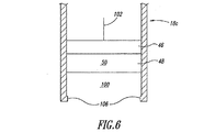
図3は、例示的な一実施形態による、作用物質インサート32を収容するレセプタクル100を示すプローブ18bの一部を示す。
FIG. 3 illustrates a portion of a
プローブ18bは、上述の作用側電極構造体36の膜、貯留槽、及び他の構造の一部又は全部を含み得る。例えば、プローブ18bは、例えば、リード線102等の導電性の電流経路を介して電源40に接続される作用側電極要素46を含み得る。プローブ18bは、例えば、電解質貯留槽48及び/又は電解質50、内側イオン選択膜52も含み得る。プローブ18bは、例えば、最外部イオン選択膜60から内側イオン選択膜52を離間させるためのスペーサ又は多孔質(例えば非選択)膜104等のスペーサをさらに含み得る。これにより、水の加水分解の発生を減らすことが有利であり得る。作用側電極構造体36の残りの部分は、作用物質インサート32内に入れることができる。
The
プローブ18bは、作用物質インサート32をレセプタクル100内に離脱可能又は取り外し可能に固定するための移動止め106又は他の保持機構を形成し得る。代替的に、作用物質インサート32は、レセプタクル100の壁と摩擦嵌めを形成するサイズ及び寸法であってもよい。
The
図4は、図3に示すプローブ18bとともに使用可能な、例示的な一実施形態による作用物質インサート32aを示す。
FIG. 4 shows an
作用物質インサート32aは、例えば、作用物質58(図2)を収容する作用物質貯留槽56を含み得る。作用物質58は、例えば、歯22(図1)の知覚を鈍麻させるのに有用な、ストロンチウム、塩化ストロンチウム、又は他の何らかのストロンチウム化合物の形態を採り得る。作用物質インサート32aは、例えば、最外部イオン選択膜60、例えば最外部イオン交換膜をも含み得る。最外部イオン選択膜60は、付加的な作用物質62(図2)を含浸させるか又は他の方法で蓄えさせることができ、その最外面66(図2)上に保持されるさらなる作用物質64(図2)を含むことができる。
The
内側剥離ライナ72aは、作用物質貯留槽56の上に、すなわちそれを覆って概ね配置され得る。外側剥離ライナ72bは、最外部イオン選択膜60の外面66によって保持されるさらなる作用物質64の上に、すなわちそれを覆って概ね配置され得る。内側剥離ライナ72aは、起電力又は電流を加える前の収容中に作用物質貯留槽56を保護することができる。外側剥離ライナ72bは、起電力又は電流を加える前の収容中にさらなる作用物質64及び/又は最外部イオン選択膜60を保護することができる。内側剥離ライナ72a及び/又は外側剥離ライナ72bは、感圧接着剤に一般的に関連する剥離ライナ等の防水材料製の選択的に剥離可能なライナであり得る。内側剥離ライナ72a及び外側剥離ライナ72bは、図2では除去された状態が図示されていることに留意されたい。
The
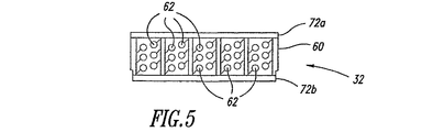
図5は、図3に示すプローブ18bとともに使用可能な、例示的な一実施形態による作用物質インサート32bを示す。
FIG. 5 shows an agent insert 32b according to an exemplary embodiment that can be used with the
作用物質インサート32bは、例えば、最外部イオン選択膜60、例えば最外部イオン交換膜を含み得る。最外部イオン選択膜60は、作用物質62を含浸させるか又は他の方法で蓄えさせることができ、その最外面66(図2)上に保持されるさらなる作用物質64(図2)を含むことができる。作用物質62、62は、例えば、歯22(図1)の知覚を鈍麻させるのに有用な、ストロンチウム、塩化ストロンチウム、又は他の何らかのストロンチウム化合物の形態を採り得る。
The agent insert 32b may include, for example, an outermost ion
作用物質インサート32bは、例えば、内側剥離ライナ72a及び外側剥離ライナ72bも含むことができ、剥離ライナ72a、72bはそれぞれ、最外部イオン選択膜60の各面の上に、すなわちそれを覆って概ね配置される。内側剥離ライナ72a及び外側剥離ライナ72bは、起電力又は電流を加える前の収容中に最外部イオン選択膜60を保護することができる。
The agent insert 32b may also include, for example, an
図6は、例示的な一実施形態による、作用物質インサート32を収容するレセプタクル100を示すプローブ18cの一部を示す。
FIG. 6 illustrates a portion of a
プローブ18cは、上述の作用側電極構造体36の膜、貯留槽、及び他の構造の一部又は全部を含み得る。例えば、プローブ18cは、例えば、リード線102等の導電性の電流経路を介して電源40に接続される作用側電極要素42を含み得る。プローブ18cは、例えば、電解質貯留槽48及び/又は電解質50も含み得る。作用側電極構造体36の残りの部分は、作用物質インサート32内に入れてもよく、又は完全に省いてもよい。
The
プローブ18cは、作用物質インサート32をレセプタクル100内に離脱可能又は取り外し可能に固定するための移動止め106又は他の保持機構を有し得る。代替的に、作用物質インサート32は、レセプタクル100の壁と摩擦嵌めを形成するサイズ及び寸法であってもよい。
The
図7は、プローブ18c(図6)とともに使用可能な、例示的な一実施形態による作用物質インサート32cを示す。
FIG. 7 illustrates an
作用物質インサート32cは、例えばバイポーラ膜108を含み得る。バイポーラ膜108の内側部分108aは、作用物質の極性とは逆の極性のイオンを選択透過させるイオン交換膜の形態を採り得るが、外側部分108bは、作用物質の極性と同じか又は同様の極性のイオンを選択透過させるイオン交換膜の形態を採り得る。バイポーラ膜108は、別個の膜から形成されてもよく、又は適当なイオン交換物質又はイオン交換基が内側部分108a及び外側部分108bそれぞれに堆積又は分配された1枚の膜であってもよい。
The
バイポーラ膜108の外側部分108bには、作用物質62を含浸させるか又は他の方法で蓄えさせることができる。さらなる作用物質64(図2)が、その最外面66(図2)上に保持されてもよい。作用物質62、64は、例えば、歯22(図1)の知覚を鈍麻させるのに有用な、ストロンチウム、塩化ストロンチウム、又は他の何らかのストロンチウム化合物の形態を採り得る。
The
作用物質インサート32cは、例えば、内側剥離ライナ72a及び外側剥離ライナ72bも含むことができ、剥離ライナ72a、72bはそれぞれ、バイポーラ膜108の各面の上に、すなわちそれを覆って概ね配置される。内側剥離ライナ72a及び外側剥離ライナ72bは、起電力又は電流を加える前の収容中にバイポーラ膜108及び作用物質62、64を保護することができる。
The
図8は、別の例示的な実施形態によるハンドヘルド作用物質送達装置10bを示す。ハンドヘルド作用物質送達装置10bは、手(図1)の指(例えば、親指以外の指(fingers))に無理なく対応する複数の凸部110及び凹部112を有する人間工学的に構成されたハンドル部分14bを有する。他の人間工学的構成も可能である。ハンドヘルド作用物質送達装置10bは、ハンドヘルド作用物質送達装置10bを外部電源16及び/又はコントローラ(図示せず)に接続するコード又はワイヤ114も含み得る。
FIG. 8 illustrates a handheld
図9は、さらなる例示的な実施形態によるハンドヘルド作用物質送達装置10cを示す。ハンドヘルド作用物質送達装置10cは、複数のプローブ18dが角度を成して(例えば90度で)上向きに延びている平坦なハンドル部分14cを有し、一般的な歯ブラシに類似し得る。プローブは、それぞれ互いに異なる。プローブはそれぞれ、外部109及び内部111(図13)を有する。プローブ18dは、ほぼ直角で図示されているが、目的の用途の特定の生物学的構造に対応するように他の角度でハンドル部分14cから延びていてもよく、プローブ18dのそれぞれが互いに異なる角度で延びていてもよい。複数のプローブ18dがあるように図示されているが、他の実施形態では、ハンドル部分14cから延びるプローブ18dの数がより多くても少なくてもよい。例えば、一実施形態は、ハンドル部分14cから直角、鋭角、又は鈍角に延びる1つのプローブ18dを含み得る。
FIG. 9 shows a handheld
図10は、別の例示的な実施形態によるハンドヘルド作用物質送達装置10dの一部を示す。ハンドヘルド作用物質送達装置10dは、プローブ形の作用物質貯留槽の形態を採り得る複数のプローブ18eを含み、そのそれぞれが、生体界面20への送達のために作用物質58、62、64(図2)を一時的に収容することが可能である。プローブ18eは、作用物質貯留槽として作用物質58、62、64を保持するのに適している本明細書で説明した形態のいずれかを取り得る。例えば、プローブ18eは、外側イオン交換膜60(図2)と同様の1つ又は複数のイオン交換膜の形態を採り得る。例えば、プローブ18eは、基板上に個別のプローブ形のイオン交換膜として形成され得る。代替的に、プローブ18eは、例えばエッチング又は蒸着によってモノリシックイオン交換膜から形成され得る。
FIG. 10 illustrates a portion of a handheld
ハンドヘルド作用物質送達装置10dは、作用物質58、62、64の極性と同じ極性の起電力を供給するように動作可能な少なくとも1つの作用側電極要素46、及び作用物質の極性とは逆の起電力を供給するように動作可能な対向電極要素76も含む。作用側電極要素46及び対向電極要素76は、1つ又は複数の電池、スーパーキャパシタ若しくはウルトラキャパシタ、及び/又は燃料電池等の電源40に電気的に接続される。作用側電極要素46は、プローブ18eの2つ以上に起電力を供給するように配置されるため、複数のプローブ18eに共通である。
The handheld active
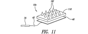
図11は、さらに別の例示的な実施形態によるハンドヘルド作用物質送達装置10eの一部を示す。ハンドヘルド作用物質送達装置10eは、ハンドル(図11には図示せず)から角度を成して延びる複数のプローブ18fを含む。
FIG. 11 illustrates a portion of a handheld agent delivery device 10e according to yet another exemplary embodiment. Handheld agent delivery device 10e includes a plurality of
ハンドヘルド作用物質送達装置10eは、少なくとも1つの作用物質貯留槽116も含む。作用物質貯留槽116は、作用物質58、62、64(図2)を一時的に保持するのに適している本明細書で説明した形態のいずれかを取り得る。例えば、作用物質貯留槽116は、外側イオン交換膜60(図2)と同様の1つ又は複数のイオン交換膜の形態を採り得る。作用物質貯留槽116は、2つ以上のプローブ18fに作用物質58、62、64(図2)を供給するように配置される。したがって、作用物質貯留槽116は、複数のプローブ18fに共通である。
Handheld agent delivery device 10 e also includes at least one
ハンドヘルド作用物質送達装置10eは、作用物質の極性と同じ極性の起電力を供給するように動作可能な少なくとも1つの作用側電極要素46、及び作用物質の極性とは逆の起電力を供給するように動作可能な対向電極76をさらに含む。作用側電極要素46及び対向電極要素76は、1つ又は複数の電池、スーパーキャパシタ若しくはウルトラキャパシタ、及び/又は燃料電池等の電源40に電気的に接続される。作用側電極要素76は、プローブ18fの2つ以上のそれぞれと流体連通している作用物質貯留槽116の2つ以上の部分に起電力を供給するように配置されるため、複数のプローブ18fに共通である。
The handheld agent delivery device 10e provides at least one working
図12は、さらに別の例示的な実施形態によるハンドヘルド作用物質送達装置10fの一部を示す。ハンドヘルド作用物質送達装置10fは、ハンドル(図12には図示せず)から角度を成して延びる複数のプローブ18gを含む。
FIG. 12 illustrates a portion of a handheld
ハンドヘルド作用物質送達装置10fは、少なくとも1つの作用物質貯留槽116も含む。作用物質貯留槽116は、作用物質58、62、64(図2)を一時的に保持するのに適している本明細書で説明した形態のいずれかを取り得る。例えば、作用物質貯留槽116は、外側イオン交換膜60(図2)と同様の1つ又は複数のイオン交換膜の形態を採り得る。作用物質貯留槽116は、2つ以上のプローブ18gに作用物質58、62、64を供給するように配置される。したがって、作用物質貯留槽116は、複数のプローブ18gに共通である。
Handheld
ハンドヘルド作用物質送達装置10fは、作用物質の極性と同じ極性の起電力を供給するように動作可能な少なくとも1つの作用側電極要素46、及び作用物質の極性とは逆の起電力を供給するように動作可能な対向電極76をさらに含む。作用側電極要素46及び対向電極要素76は、1つ又は複数の電池、燃料電池、及び/又はスーパーキャパシタ若しくはウルトラキャパシタ等の電源40に電気的に接続される。作用側電極要素46は、プローブ18gの2つ以上のそれぞれと流体連通している作用物質貯留槽116の2つ以上の部分に起電力を供給するように配置されるため、複数のプローブ18gに共通である。
The handheld active
ハンドヘルド作用物質送達装置10fは、作用物質貯留槽116と作用側電極要素46との間に配置される少なくとも1つの電解質貯留槽48をオプションで含む。電解質貯留槽48は、いくつかの実施形態では作用物質58、62、64(図2)と同じ物質であり得る電解質50(図2)を収容可能である。電解質貯留槽48は、本明細書で説明した形態のいずれかを取り得る。電解質貯留槽48及び電解質50の利点は、上述してあるため簡略化のためにここでは繰り返さない。
The handheld
ハンドヘルド作用物質送達装置10fは、電解質貯留槽48を作用物質貯留槽116から分離する少なくとも1つの内側イオン選択膜52もオプションで含む。内側イオン選択膜52は、本明細書で説明した形態のいずれかを取り得る。内側イオン選択膜52の利点は、上述してあるため簡略化のためにここでは繰り返さない。
The handheld
図13は、さらに別の例示的な実施形態によるハンドヘルド作用物質送達装置10gの一部破断概略図を示す。ハンドヘルド作用物質送達装置10gは、ハンドル(図13には図示せず)から角度を成して延びる複数のプローブ18hを含む。図示のように、プローブ18hの1つは、その内部構造よりよく示すために破断されている。
FIG. 13 shows a partially broken schematic view of a handheld
プローブ18hはそれぞれ、各自の作用物質貯留槽118及び作用側電極要素120を含む。作用物質貯留槽118は、本明細書で説明した様々な形態のいずれかを取り得る。作用側電極要素120は、本明細書で説明した様々な形態のいずれかを取り得る。
Each
プローブ18hはそれぞれ、各自の電解質貯留槽122及び/又は膜124をオプションで含み得る。電解質貯留槽122及び/又は電解質50(図2)は、本明細書で説明した様々な形態のいずれかを取り得る。膜124は、限定はされないが、多孔質膜、半透過膜、イオン選択膜、イオン交換膜、及び/又はバイポーラ膜を含む本明細書で説明した様々な形態のいずれかを取り得る。
Each
要約書に記載されるものを含めて、例示的な実施形態の上記の説明は、網羅的であることも特許請求の範囲を開示されたのと全く同じ形態に限定することも意図されない。具体的な実施形態及び実施例が説明のために本明細書に記載されているが、当業者に認識されるように、本発明の精神及び範囲から逸脱せずに様々な同等の変更を行うことができる。本明細書で提供した本発明の教示は、必ずしも上記で概説した例示的なイオントフォレーシス作用物質システム及び装置に限らず、他の薬剤送達システム及び装置に適用することができる。例えば、実施形態によっては付加的な構造を含み得る。例えば、実施形態によっては、作用側電極要素36及び対向電極要素38に加えられる電圧、電流、又は電力を制御する制御回路又はサブシステムを含み得る。さらに例えば、実施形態によっては、最外部作用側電極イオン選択膜60と生体界面20との間に挟まれる界面層を含み得る。実施形態によっては、付加的なイオン選択膜、イオン交換膜、半透過膜、及び/又は多孔質膜、並びに付加的な電解質及び/又は緩衝剤用の貯留槽を備え得る。
The above description of example embodiments, including what is described in the abstract, is not intended to be exhaustive or to limit the claims to the exact same form as disclosed. While specific embodiments and examples are described herein for purposes of illustration, various equivalent modifications will be made without departing from the spirit and scope of the invention, as will be appreciated by those skilled in the art. be able to. The teachings of the invention provided herein are not necessarily limited to the exemplary iontophoretic agent systems and devices outlined above, but can be applied to other drug delivery systems and devices. For example, some embodiments may include additional structures. For example, some embodiments may include a control circuit or subsystem that controls the voltage, current, or power applied to the working
被験体に電気刺激を伝えるために被験体の皮膚又は装置内に電気的インタフェースを提供する様々な導電性ヒドロゲルが、医療分野において既知であり用いられている。ヒドロゲルは皮膚を水化するため、ヒドロゲルを通して電気刺激による熱傷から保護するとともに、皮膚を膨張させて活性成分のより効率的な移送を可能にする。このようなヒドロゲルの例は、米国特許第6,803,420号、第6,576,712号、第6,908,681号、第6,596,401号、第6,329,488号、第6,197,324号、第5,290,585号、第6,797,276号、第5,800,685号、第5,660,178号、第5,573,668号、第5,536,768号、第5,489,624号、第5,362,420号、第5,338,490号、及び第5,240,995号に開示されており、これらの全体が参照により本明細書に援用される。このようなヒドロゲルのさらなる例は、米国特許出願第2004/166147号、第2004/105834号、及び第2004/247655号に開示されており、これらの全体が参照により本明細書に援用される。様々なヒドロゲル及びヒドロゲルシートの製品ブランド名として、CoriumによるCorplex(商標)、3MによるTegagel(商標)、BDによるPuraMatrix(商標)、BardによるVigilon(商標)、Conmed CorporationによるClearSite(商標)、Smith & NephewによるFlexiGel(商標)、MedlineによるDerma−Gel(商標)、Johnson & JohnsonによるNu−Gel(商標)、及びKendallによるCuragel(商標)、又はSun Contact Lens Co., Ltd.から入手可能なアクリルヒドロゲル膜が挙げられる。 A variety of conductive hydrogels that provide an electrical interface within a subject's skin or device to deliver electrical stimulation to the subject are known and used in the medical field. The hydrogel hydrates the skin, thus protecting it from electrical stimulation through the hydrogel and expanding the skin to allow more efficient transfer of the active ingredient. Examples of such hydrogels are US Pat. Nos. 6,803,420, 6,576,712, 6,908,681, 6,596,401, 6,329,488, 6,197,324, 5,290,585, 6,797,276, 5,800,685, 5,660,178, 5,573,668, 5 , 536,768, 5,489,624, 5,362,420, 5,338,490, and 5,240,995, which are incorporated by reference in their entirety. Incorporated herein by reference. Further examples of such hydrogels are disclosed in US Patent Application Nos. 2004/166147, 2004/105834, and 2004/247655, which are hereby incorporated by reference in their entirety. Product brand names for various hydrogels and hydrogel sheets include Corplex ™ by Corium, Tagegel ™ by 3M, PuraMatrix ™ by BD, Vigilon ™ by Bard, ClearSite ™ by Conmed Corporation, Smith & FlexiGel (TM) by Nephew, Derma-Gel (TM) by Medline, Nu-Gel (TM) by Johnson & Johnson, and Curagel (TM) by Kendall, or acrylic hydrogels available from Sun Contact Lens Co., Ltd. A membrane is mentioned.
イオントフォレーシス中、電極構造体を横断する起電力は、上記のように、生体界面を通して、生体組織中への、荷電活性物質分子並びにイオン及び他の荷電構成成分の移動をもたらす。この移動は、界面を越えた生体組織内の活性物質、イオン及び/又は他の荷電構成成分の蓄積をもたらし得る。イオントフォレーシス中、反発力に応答する荷電分子の移動のほかに、電極及び生体界面を通して組織中への溶媒(例えば水)の電気浸透流も存在する。或る種の実施形態では、電気浸透溶媒流は、荷電分子及び非荷電分子の両方の移動を増強する。電気浸透溶媒流による移動増強は、特に分子のサイズ増大に伴って起こり得る。 During iontophoresis, the electromotive force across the electrode structure results in the movement of charged active substance molecules and ions and other charged components through the biological interface and into the biological tissue, as described above. This migration can result in the accumulation of active substances, ions and / or other charged components within the biological tissue across the interface. During iontophoresis, in addition to the movement of charged molecules in response to repulsive forces, there is also an electroosmotic flow of solvent (eg water) through the electrode and biological interface into the tissue. In certain embodiments, electroosmotic solvent flow enhances the migration of both charged and uncharged molecules. Migration enhancement due to electroosmotic solvent flow can occur, particularly with increasing molecular size.
或る種の実施形態では、活性物質は高分子量分子であり得る。或る種の態様では、分子は極性高分子電解質であり得る。或る種の他の態様では、分子は親油性であり得る。或る種の実施形態では、活性電極内の条件下で、このような分子は荷電され得るし、そして低正味電荷を有するか、又は非荷電であり得る。或る種の態様では、このような活性物質は、小さなより高度に荷電された活性物質の移動に対比して、イオントフォレーシス反発力下では十分に移動し得ない。したがってこれらの高分子量活性物質は、主に電気浸透溶媒流により、生体界面を介して下に或る組織中に運搬され得る。或る種の実施形態では、高分子量の高分子電解質活性物質は、タンパク質、ポリペプチド又は核酸であり得る。 In certain embodiments, the active agent can be a high molecular weight molecule. In certain embodiments, the molecule can be a polar polyelectrolyte. In certain other embodiments, the molecule can be lipophilic. In certain embodiments, under conditions within the active electrode, such molecules can be charged and have a low net charge or can be uncharged. In certain embodiments, such active agents cannot move sufficiently under iontophoretic repulsion, as opposed to the movement of small, more highly charged active agents. These high molecular weight active substances can therefore be transported down into certain tissues via the biological interface, mainly by electroosmotic solvent flow. In certain embodiments, the high molecular weight polyelectrolyte active can be a protein, polypeptide or nucleic acid.
上記の種々の実施形態は、有益には、種々の微細構造、例えばマイクロニードルを用い得る。マイクロニードル及びマイクロニードルアレイ、それらの製造及び使用が記載されている。マイクロニードルは、独立して、又はアレイで、中空、固体及び透過性、固体及び半透性、或いは固体及び非透過性であり得る。固体、非透過性マイクロニードルはさらに、それらの外表面に沿って溝を含み得る。複数のマイクロニードルからなるマイクロニードルアレイは、種々の形状、例えば長方形又は円形で配列され得る。マイクロニードル及びマイクロニードルアレイは、種々の材料、例えばケイ素、二酸化ケイ素、成型プラスチック材料、例えば生分解性ポリマー又は非生分解性ポリマー、セラミック、並びに金属から製造され得る。マイクロニードルは、独立して、又はアレイで、中空開口部を通して、固体透過性物質又は半透性物質を通して、或いは外部溝を介して、流体を投与するか又はサンプリングするために用いられ得る。マイクロニードル装置は、例えば生体界面、例えば皮膚又は粘膜を介して、生きている身体に種々の化合物及び組成物を送達するために用いられる。或る種の実施形態では、化合物及び活性物質は、生体界面に又は生体界面を介して送達され得る。例えば皮膚を介して化合物又は組成物を送達するのに際しては、個々の或いはアレイでの(単一又は複数の)マイクロニードルの長さ、及び/又は挿入深度は、化合物又は組成物の投与が表皮中だけ、表皮を通して真皮、又は皮下に投与されるかを制御するために用いられ得る。或る種の実施形態では、マイクロニードル装置は、高分子量化合物及び活性物質、例えばタンパク質、ペプチド及び/又は核酸を含むもの並びにその対応する組成物の送達のために有用であり得る。例えば流体がイオン性溶液である或る種の実施形態では、(単一又は複数の)マイクロニードル又は(単一又は複数の)マイクロニードルアレイは電源とマイクロニードル(単数又は複数)の先端との間の電気的連続性を提供し得る。(単一又は複数の)マイクロニードル又は(単一又は複数の)マイクロニードルアレイは、本明細書中に記載されるようなイオントフォレーシス法により、化合物又は組成物を送達するか又はサンプリングするために有益に用いられ得る。或る種の実施形態では、例えばアレイ中の複数のマイクロニードルは、有益には、イオントフォレーシス装置の最外部生体界面の接触表面上に形成され得る。このような装置により送達されるか又はサンプリングされる化合物又は組成物は、例えば高分子量分子又は活性物質、例えばタンパク質、ペプチド及び/又は核酸を含み得る。 The various embodiments described above can beneficially use various microstructures, such as microneedles. Microneedles and microneedle arrays, their manufacture and use are described. The microneedles can be hollow, solid and permeable, solid and semi-permeable, or solid and non-permeable, independently or in an array. Solid, non-permeable microneedles can further include grooves along their outer surface. A microneedle array composed of a plurality of microneedles can be arranged in various shapes, for example, rectangular or circular. Microneedles and microneedle arrays can be made from a variety of materials such as silicon, silicon dioxide, molded plastic materials such as biodegradable or non-biodegradable polymers, ceramics, and metals. Microneedles can be used to administer or sample fluids independently or in an array, through a hollow opening, through a solid or semi-permeable material, or through an external groove. Microneedle devices are used to deliver various compounds and compositions to the living body, for example, via a biological interface, such as the skin or mucous membrane. In certain embodiments, the compound and the active agent can be delivered to or via the biological interface. For example, in delivering a compound or composition through the skin, the length of the microneedle (single or multiple) and / or depth of insertion, either individually or in an array, can be determined by the administration of the compound or composition. It can only be used to control whether it is administered through the epidermis, through the epidermis, or subcutaneously. In certain embodiments, the microneedle device may be useful for delivery of high molecular weight compounds and active agents, such as those comprising proteins, peptides and / or nucleic acids, and their corresponding compositions. For example, in certain embodiments where the fluid is an ionic solution, the microneedle (single or multiple) or microneedle array (single or multiple) is a combination of the power source and the tip of the microneedle (s). It can provide electrical continuity between. The microneedle (single or multiple) or microneedle array (single or multiple) delivers or samples a compound or composition by iontophoresis methods as described herein. Can be beneficially used. In certain embodiments, for example, a plurality of microneedles in an array can be beneficially formed on the outermost biological interface contact surface of the iontophoresis device. A compound or composition delivered or sampled by such a device may comprise, for example, high molecular weight molecules or active substances such as proteins, peptides and / or nucleic acids.
或る種の実施形態では、化合物又は組成物は、生体界面に、生体界面の中に、又は生体界面を介して、活性物質を送達するために、電源に電気的に結合された作用側電極構造体及び対向電極構造体を含むイオントフォレーシス装置により送達され得る。作用側電極構造体は、以下のものを包含する:電源の正電極に接続される第一の電極部材、第一の電極部材と接触し、そして第一の電極部材を介して電圧を印加される活性物質溶液を有する活性物質貯留槽、マイクロニードルアレイであり得、活性物質貯留槽の前面に対面して配置される生体界面接触部材、並びにこれらの部材を収容する第一のカバー又は容器。対向電極構造体は、以下のものを包含する:電源の負電極に接続される第二の電極部材、第二の電極部材と接触し、そして第二の電極部材を介して電圧が印加される電解質を担持する電解質貯留槽、並びにこれらの部材を収容する第二のカバー又は容器。 In certain embodiments, the compound or composition is a working electrode electrically coupled to a power source to deliver an active agent to, into or through the biological interface. It can be delivered by an iontophoresis device comprising a structure and a counter electrode structure. The working electrode structure includes: a first electrode member connected to the positive electrode of the power source, in contact with the first electrode member, and applied with a voltage via the first electrode member. An active substance storage tank having an active substance solution, a microneedle array, a biological interface contact member disposed facing the front surface of the active substance storage tank, and a first cover or container containing these members. The counter electrode structure includes the following: a second electrode member connected to the negative electrode of the power source, in contact with the second electrode member, and a voltage is applied through the second electrode member An electrolyte storage tank for carrying an electrolyte, and a second cover or container for housing these members.
或る種の他の実施形態では、化合物又は組成物は、生体界面に、生体界面の中に、又は生体界面を介して、活性物質を送達するために、電源に電気的に結合された作用側電極構造体及び対向電極構造体を含むイオントフォレーシス装置により送達され得る。作用側電極構造体は、以下のものを包含する:電源の正電極に接続される第一の電極部材、第一の電極部材と接触し、そして第一の電極部材を介して電圧を印加される電解質を有する第一の電解質貯留槽、第一の電解質貯留槽の前面に配置される第一の陰イオン交換膜、第一の陰イオン交換膜の前面に対して配置される活性物質貯留槽、マイクロニードルアレイであり得、活性物質貯留槽の前面に対面して配置される生体界面接触部材、並びにこれらの部材を収容する第一のカバー又は容器。対向電極構造体は、以下のものを包含する:電源の負電極に接続される第二の電極部材、第二の電極部材と接触し、そして第二の電極部材を介して電圧を印加される電解質を担持する第二の電解質貯留槽、第二の電解質貯留槽の前面に配置される陽イオン交換膜、陽イオン交換膜の前面に対して配置され、そして第二の電解質貯留槽及び陽イオン交換膜を介して第二の電極部材から電圧が印加される電解質を担持する第三の電解質貯留槽、第三の電解質貯留槽の前面に対して配置される第二の陰イオン交換膜、並びにこれらの部材を収容する第二のカバー又は容器。 In certain other embodiments, the compound or composition has an action that is electrically coupled to a power source to deliver an active agent to, into or through the biological interface. It can be delivered by an iontophoresis device comprising a side electrode structure and a counter electrode structure. The working electrode structure includes: a first electrode member connected to the positive electrode of the power source, in contact with the first electrode member, and applied with a voltage via the first electrode member. A first electrolyte storage tank having an electrolyte, a first anion exchange membrane disposed in front of the first electrolyte storage tank, and an active substance storage tank disposed in front of the first anion exchange membrane A biointerface contact member that can be a microneedle array and is disposed to face the front surface of the active substance reservoir, and a first cover or container that houses these members. The counter electrode structure includes the following: a second electrode member connected to the negative electrode of the power source, in contact with the second electrode member, and applied with a voltage via the second electrode member A second electrolyte reservoir holding the electrolyte, a cation exchange membrane disposed in front of the second electrolyte reservoir, disposed against the front of the cation exchange membrane, and the second electrolyte reservoir and cation A third electrolyte reservoir holding an electrolyte to which a voltage is applied from the second electrode member via the exchange membrane, a second anion exchange membrane disposed with respect to the front surface of the third electrolyte reservoir, and A second cover or container that houses these members.
マイクロニードル装置、それらの使用及び製造についての或る程度の詳細は、米国特許第6,256,533号、同第6,312,612号、同第6,334,856号、同第6,379,324号、同第6,451,240号、同第6,471,903号、同第6,503,231号、同第6,511,463号、同第6,533,949号、同第6,565,532号、同第6,603,987号、同第6,611,707号、同第6,663,820号、同第6,767,341号、同第6,790,372号、同第6,815,360号、同第6,881,203号、同第6,908,453号及び同第6,939,311号(これらの記載内容はすべて、参照により本明細書中で援用される)に開示されている。その中の教示のいくつか又はすべてが、マイクロニードル装置、それらの製造、並びにイオントフォレーシス用途におけるそれらの使用に適用され得る。 Some details on the microneedle devices, their use and manufacture are described in US Pat. Nos. 6,256,533, 6,312,612, 6,334,856, 379,324, 6,451,240, 6,471,903, 6,503,231, 6,511,463, 6,533,949, 6,565,532, 6,603,987, 6,611,707, 6,663,820, 6,767,341, 6,790 No. 372, No. 6,815,360, No. 6,881,203, No. 6,908,453 and No. 6,939,311 (all of which are incorporated herein by reference) (Incorporated in the specification). Some or all of the teachings therein can be applied to microneedle devices, their manufacture, and their use in iontophoresis applications.
上記の様々な実施形態を組合せて、さらなる実施形態を提供することができる。本明細書で言及され、且つ/又は出願データシートに列挙されるすべての米国特許、米国特許出願公開、米国特許出願、外国特許、外国特許出願及び非特許出版物は、下記に列記のものを非限定的に含めて、その全体が参照により本明細書に組み込まれる。
特許第3040517号として2000年3月3日に発行され、特開平04−297277号公報を有する1991年3月27日に出願された特願平03−86002号公報、特開2000−229128号公報を有する1999年2月10日に出願された特願平11−033076号公報、特開2000−229129号公報を有する1999年2月12日に出願された特願平11−033765号公報、特開2000−237326号公報を有する1999年2月19日に出願された特願平11−041415号公報、特開2000−237327号公報を有する1999年2月19日に出願された特願平11−041416号公報、特開2000−237328号公報を有する1999年2月22日に出願された特願平11−042752号公報、特開2000−237329号公報を有する1999年2月22日に出願された特願平11−042753号公報、特開2000−288098号公報を有する1999年4月6日に出願された特願平11−099008号公報、特開2000−288097号公報を有する1999年4月6日に出願された特願平11−099009号公報、PCT公開番号WO03037425を有する2002年5月15日に出願されたPCT特許出願WO2002JP4696、2004年3月9日に出願された米国特許出願第10/488970号、2004年10月29日に出願された特願2004/317317号公報、2004年11月16日に出願された米国仮特許出願第60/627,952号、2004年11月30日に出願された特願2004−347814号公報、2004年12月9日に出願された特願2004−357313号公報、2005年2月3日に出願された特願2005−027748号公報、2005年3月22日に出願された特願2005−081220号公報、2005年9月30日に出願された米国仮特許出願第60/722,759号。
The various embodiments described above can be combined to provide further embodiments. All U.S. patents, U.S. patent application publications, U.S. patent applications, foreign patents, foreign patent applications and non-patent publications referred to herein and / or listed in the application data sheet are listed below. Incorporated herein by reference in its entirety, including without limitation.
Japanese Patent Application No. 03-86002, Japanese Patent Application No. 2000-229128, which was issued on March 3, 2000 as Japanese Patent No. 3040517 and was filed on March 27, 1991 having Japanese Patent Application Laid-Open No. 04-297277. Japanese Patent Application No. 11-033076, filed on Feb. 10, 1999, and Japanese Patent Application No. 11-033765, filed on Feb. 12, 1999, having Japanese Patent Application Laid-Open No. 2000-229129. Japanese Patent Application No. 11-041415, filed on Feb. 19, 1999, which has a gazette of Japanese Patent Application No. 2000-237326, and Japanese Patent Application No. 11, filed on Feb. 19, 1999, which has a Japanese Patent Application Laid-Open No. 2000-237327. Japanese Patent Application No. 11-0427, filed on Feb. 22, 1999, having JP-A-041416 and JP-A-2000-237328. No. 2 and Japanese Patent Application No. 11-042753 filed on Feb. 22, 1999 having JP-A 2000-237329, and filed on Apr. 6, 1999 having JP-A 2000-288098. Japanese Patent Application No. 11-0909008, Japanese Patent Application No. 11-090909 filed on Apr. 6, 1999 having Japanese Patent Application Laid-Open No. 2000-288097, May 15, 2002 having PCT Publication No. WO03037425 PCT patent application WO2002JP4696 filed in US Patent Application No. 10/488970 filed on March 9, 2004, Japanese Patent Application No. 2004/317317 filed on October 29, 2004, November 2004 U.S. Provisional Patent Application No. 60 / 627,952 filed on 16th November 30, 2004 Japanese Patent Application No. 2004-347814 filed, Japanese Patent Application No. 2004-357313 filed on December 9, 2004, Japanese Patent Application No. 2005-027748 filed on February 3, 2005, March 2005 Japanese Patent Application No. 2005-081220 filed on May 22, and US Provisional Patent Application No. 60 / 722,759 filed on September 30, 2005.
種々の実施形態の態様は、必要な場合、さらなる実施形態を提供するために種々の特許、出願及び出版物のシステム、回路及び概念を用いるように変形され得る。いくつかの実施形態は、上記の膜、貯留槽及びその他の構造のすべてを包含し得るが、他の実施形態は、膜、貯留槽又は他の構造のいくつかを省略し得る。さらなる他の実施形態は、一般的に上記した膜、貯留槽及び構造の付加的なものを用いることができる。さらなる実施形態は、一般的に上記した膜、貯留槽及び構造の付加的なものを用いながら、上記の膜、貯留槽及び構造のいくつかを省略することができる。 Aspects of the various embodiments can be modified to use various patent, application and publication systems, circuits and concepts to provide further embodiments, if necessary. Some embodiments may include all of the membranes, reservoirs, and other structures described above, while other embodiments may omit some of the membranes, reservoirs, or other structures. Still other embodiments can use additional ones of the membranes, reservoirs and structures generally described above. Further embodiments may omit some of the membranes, reservoirs and structures described above, while generally using additional ones of the membranes, reservoirs and structures described above.
上記の詳細な記載にかんがみて、様々な変更が為され得る。概して、添付の特許請求の範囲においては、用いられる用語は、本明細書及び添付の特許請求の範囲に開示される特定の実施形態に限定するように解釈されるべきでなく、添付の特許請求の範囲に従って動作するすべてのシステム、装置及び/又は方法を含むように解釈されるべきである。したがって本発明は本開示により限定されなるものでなく、その範囲は添付の特許請求の範囲により専ら判定されるべきものである。 Various modifications can be made in light of the above detailed description. In general, in the appended claims, the terms used should not be construed as limited to the specific embodiments disclosed in the specification and the appended claims, but the appended claims. Should be construed to include all systems, devices, and / or methods operating in accordance with the scope of: Accordingly, the invention is not to be limited by the disclosure, but its scope should be determined entirely by the appended claims.
Claims (41)
把持されるサイズ及び寸法のハンドルと、
前記ハンドルから延びる複数のプローブと、
前記ハンドル内に少なくとも部分的に配置される対向電極構造体であって、第1の極性の電位を供給するように動作可能な少なくとも1つの対向電極要素を備え、前記ハンドルが把持されると第1の生体界面と前記対向電極要素との間に導電路を提供するように動作可能である、対向電極構造体と、
前記複数のプローブに近接して配置される少なくとも1つの作用側電極構造体であって、前記第1の極性とは異なる第2の極性の電位を供給するように動作可能な少なくとも1つの作用側電極要素を備え、前記プローブが第2の生体界面に近接して位置付けられると該第2の生体界面と前記作用側電極要素との間に導電路を提供するように動作可能である、作用側電極構造体光とを備え、
前記第1の生体界面及び前記第2の生体界面はそれぞれ前記生体の一部であり、前記作用物質の少なくとも一部は、前記少なくとも1つの作用側電極要素と前記プローブのそれぞれの外部との間に配置される、電源の影響下で生体に作用物質を送達する装置。 A device for delivering an active substance to a living body under the influence of a power source,
A handle of size and dimension to be gripped;
A plurality of probes extending from the handle;
A counter electrode structure disposed at least partially within the handle, the counter electrode structure comprising at least one counter electrode element operable to supply a potential of a first polarity; A counter electrode structure operable to provide a conductive path between one biological interface and the counter electrode element;
At least one working electrode structure disposed proximate to the plurality of probes, wherein the working electrode is operable to supply a potential of a second polarity different from the first polarity. A working side comprising an electrode element and operable to provide a conductive path between the second biological interface and the working electrode element when the probe is positioned proximate to a second biological interface; Electrode structure light,
The first biological interface and the second biological interface are each a part of the living body, and at least a part of the active substance is between the at least one working electrode element and the outside of the probe. An apparatus for delivering an active substance to a living body under the influence of a power source, disposed in
前記電解質と前記最外部イオン選択膜との間に配置されて、前記第1の極性のイオンを選択透過させるイオン交換膜である、内側イオン選択膜をさらに備える、請求項10に記載の装置。 The outermost ion selective membrane is an ion exchange membrane that selectively transmits ions of the second polarity, and the device includes:
The apparatus according to claim 10, further comprising an inner ion selective membrane that is disposed between the electrolyte and the outermost ion selective membrane and is an ion exchange membrane that selectively transmits ions of the first polarity.
把持されるサイズ及び構成の外周を有するハンドルと、
前記ハウジングの前記ハンドル部分に少なくとも部分的に収容される対向電極構造体であって、前記電源から第1の極性の電位を供給するように動作可能な対向電極要素を備える、対向電極構造体と、
複数のプローブ、少なくとも1つの作用側電極要素、及び少なくとも1つの作用物質貯留槽を含む少なくとも1つの作用側電極構造体であって、前記複数のプローブはそれぞれ、前記ハンドルから延びて互いに異なる外部を有し、前記少なくとも1つの作用物質貯留槽は、前記少なくとも1つの作用側電極要素と前記プローブの前記外部との間に配置され、前記少なくとも1つの作用側電極要素は、前記第1の極性とは逆の第2の極性の電位を前記作用物質貯留槽に供給するように動作可能であることにより、少なくとも一部の作用物質が、前記第2の極性の電位の供給に応答して前記プローブの前記外部を通して前記作用物質貯留槽から送り出されるようにする、少なくとも1つの作用側電極構造体とを備える、生体の2つの異なる部分を介した電源からの回路経路を形成することにより生体に作用物質を送達するイオントフォレーシス装置。 An iontophoresis device for delivering an agent to a living body by forming a circuit path from a power source through two different parts of the living body,
A handle having an outer periphery of the size and configuration to be gripped;
A counter electrode structure at least partially housed in the handle portion of the housing, the counter electrode structure comprising a counter electrode element operable to supply a first polarity potential from the power source; ,
At least one working electrode structure including at least one working electrode element and at least one working substance reservoir, wherein each of the plurality of probes extends from the handle and has a different exterior. The at least one active substance reservoir is disposed between the at least one active electrode element and the exterior of the probe, the at least one active electrode element having the first polarity; Is operable to supply a reverse second polarity potential to the agent reservoir so that at least some of the agents are responsive to the supply of the second polarity potential. Two different parts of the living body comprising at least one working electrode structure that is adapted to be delivered from the active substance reservoir through the exterior of Iontophoresis device for delivering an agent to a biological by forming a circuit path from the power source.
把持されるサイズ及び構成の外周を有するハンドルと、
前記ハウジングの前記ハンドル部分に少なくとも部分的に収容される対向電極構造体であって、前記電源から第1の極性の電位を供給するように動作可能な対向電極要素を備える、対向電極構造体と、
それぞれが前記ハンドルから延びて互いに異なる外部を有する複数のプローブ形の作用物質貯留槽、及び少なくとも1つの作用側電極要素を含む、少なくとも1つの作用側電極構造体であって、前記少なくとも1つの作用側電極要素は、前記第1の極性とは逆の第2の極性の電位を前記作用物質貯留槽に供給するように動作可能であることにより、少なくとも一部の作用物質が、前記第2の極性の電位の供給に応答して前記作用物質貯留槽から送り出されるようにする、少なくとも1つの作用側電極構造体とを備える、生体の2つの異なる部分を介した電源からの回路経路を形成することにより生体に作用物質を送達するイオントフォレーシス装置。 An iontophoresis device for delivering an agent to a living body by forming a circuit path from a power source through two different parts of the living body,
A handle having an outer periphery of the size and configuration to be gripped;
A counter electrode structure at least partially housed in the handle portion of the housing, the counter electrode structure comprising a counter electrode element operable to supply a first polarity potential from the power source; ,
At least one working electrode structure comprising a plurality of probe-shaped active substance reservoirs each extending from the handle and having different exteriors and at least one working electrode element, wherein the at least one action The side electrode element is operable to supply a potential of a second polarity opposite to the first polarity to the agent reservoir so that at least a portion of the agent is in the second polarity. Forming a circuit path from the power supply via two different parts of the living body, comprising at least one working electrode structure that is adapted to be delivered from the active substance reservoir in response to the supply of a polar potential An iontophoresis device that delivers an active substance to a living body.
電源と、
前記電源への有効電流経路を介して前記生体に作用物質を積極的に送達するための、前記生体の歯に近接して選択的に配置可能な複数のプローブ手段と、
前記生体を介した前記電源への帰還電流経路を形成するための、前記生体によって選択的に把持可能なハンドル手段と
を備える、生体に作用物質を送達する作用物質送達装置。 An agent delivery device for delivering an agent to a living body,
Power supply,
A plurality of probe means selectively proximate to the teeth of the living body for actively delivering an active substance to the living body via an effective current path to the power source;
An active substance delivery device for delivering an active substance to a living body, comprising handle means that can be selectively gripped by the living body to form a return current path to the power source via the living body.
Applications Claiming Priority (3)
| Application Number | Priority Date | Filing Date | Title |
|---|---|---|---|
| US72275905P | 2005-09-30 | 2005-09-30 | |
| US11/514,296 US20070232983A1 (en) | 2005-09-30 | 2006-08-30 | Handheld apparatus to deliver active agents to biological interfaces |
| PCT/US2006/036892 WO2007041016A2 (en) | 2005-09-30 | 2006-09-21 | Handheld apparatus to deliver active agents to biological interfaces |
Publications (1)
| Publication Number | Publication Date |
|---|---|
| JP2009509643A true JP2009509643A (en) | 2009-03-12 |
Family
ID=37906657
Family Applications (1)
| Application Number | Title | Priority Date | Filing Date |
|---|---|---|---|
| JP2008533458A Pending JP2009509643A (en) | 2005-09-30 | 2006-09-21 | Handheld device for delivering an agent to a biological interface |
Country Status (8)
| Country | Link |
|---|---|
| US (1) | US20070232983A1 (en) |
| EP (1) | EP1928541A2 (en) |
| JP (1) | JP2009509643A (en) |
| KR (1) | KR20080058434A (en) |
| BR (1) | BRPI0616613A2 (en) |
| CA (1) | CA2623557A1 (en) |
| RU (1) | RU2008117115A (en) |
| WO (1) | WO2007041016A2 (en) |
Cited By (1)
| Publication number | Priority date | Publication date | Assignee | Title |
|---|---|---|---|---|
| JP6905770B1 (en) * | 2020-07-01 | 2021-07-21 | アイオニック株式会社 | Facial equipment and facial equipment kit |
Families Citing this family (16)
| Publication number | Priority date | Publication date | Assignee | Title |
|---|---|---|---|---|
| US8386030B2 (en) | 2005-08-08 | 2013-02-26 | Tti Ellebeau, Inc. | Iontophoresis device |
| US8295922B2 (en) | 2005-08-08 | 2012-10-23 | Tti Ellebeau, Inc. | Iontophoresis device |
| US20070060860A1 (en) * | 2005-08-18 | 2007-03-15 | Transcutaneous Technologies Inc. | Iontophoresis device |
| BRPI0616165A2 (en) | 2005-09-15 | 2011-06-07 | Tti Ellebeau Inc | rod type iontophoresis device |
| NZ594136A (en) | 2006-06-15 | 2013-03-28 | Seagull Ip Pty Ltd | Delivery of bound material from body to surface using ultrasonic signal |
| TWM322238U (en) * | 2006-11-28 | 2007-11-21 | Shy-Ming Shih | Toothbrush structure with electronic circuit |
| CA2671069A1 (en) | 2006-12-01 | 2008-06-12 | Tti Ellebeau, Inc. | Systems, devices, and methods for powering and/or controlling devices, for instance transdermal delivery devices |
| JP2008183378A (en) * | 2007-01-31 | 2008-08-14 | Matsushita Electric Works Ltd | Oral hygiene apparatus |
| DE102008026067A1 (en) * | 2008-05-30 | 2010-01-14 | Schaffrath, Paul, Dr. | Device for improving oral hygiene |
| US20130071807A1 (en) * | 2011-09-20 | 2013-03-21 | Alexander Franz Doll | Iontophoretic oral care devices with automatic oral care implement detection and mode selection |
| EP2994189A4 (en) * | 2013-05-06 | 2017-01-18 | Mupharma Pty Ltd | Non-invasive agent applicator |
| EP3139990A4 (en) | 2014-05-06 | 2018-01-17 | Mupharma Pty Ltd | Non-invasive agent applicator |
| US11103058B2 (en) * | 2017-06-27 | 2021-08-31 | Colgate-Palmolive Company | Oral care implement |
| EP3682941B1 (en) * | 2019-01-18 | 2021-11-10 | Ecole Polytechnique Federale De Lausanne (EPFL) EPFL-TTO | Biomedical device comprising a mechanically adaptive member |
| KR20220074962A (en) * | 2019-11-27 | 2022-06-03 | 이 잉크 캘리포니아 엘엘씨 | Benefit agent delivery system comprising microcells having an electro-erodible sealing layer |
| WO2021257426A1 (en) * | 2020-06-15 | 2021-12-23 | Church & Dwight Co., Inc. | Ionic toothbrush |
Citations (6)
| Publication number | Priority date | Publication date | Assignee | Title |
|---|---|---|---|---|
| JPS5779437U (en) * | 1980-11-04 | 1982-05-17 | ||
| JPS63288102A (en) * | 1987-03-09 | 1988-11-25 | ワング リング | Microelectronics ionizing apparatus for treating oral disease |
| JP2000510012A (en) * | 1996-05-08 | 2000-08-08 | ジ・エイピーエス・オーガニゼイション・リミテッド・ライアビリティ・パートナーシップ | Drug delivery device by iontophoresis and method of using the same |
| WO2003061758A1 (en) * | 2002-01-24 | 2003-07-31 | Hisamitsu Pharmaceutical Co., Inc. | Electrode structure |
| JP2004188188A (en) * | 2002-11-27 | 2004-07-08 | Tokuyama Corp | Device for iontophoresis |
| WO2005004979A1 (en) * | 2003-06-30 | 2005-01-20 | Johnson & Johnson Consumer Companies, Inc. | Device for treatment of human or animal barrier membranes |
Family Cites Families (97)
| Publication number | Priority date | Publication date | Assignee | Title |
|---|---|---|---|---|
| DE1003395B (en) * | 1953-09-16 | 1957-02-28 | Sten Ingmar Wahlin | Dental care device to prevent the development of caries |
| US3520297A (en) * | 1967-01-31 | 1970-07-14 | Chemway Corp | Iontophoretic toothbrush |
| DE2626294C3 (en) * | 1976-06-11 | 1980-01-10 | Siemens Ag, 1000 Berlin Und 8000 Muenchen | Implantable dosing device |
| US4250878A (en) * | 1978-11-22 | 1981-02-17 | Motion Control, Inc. | Non-invasive chemical species delivery apparatus and method |
| JPS5810066A (en) * | 1981-07-10 | 1983-01-20 | 株式会社アドバンス | Plaster structure for ion tofuorese |
| US4640689A (en) * | 1983-08-18 | 1987-02-03 | Drug Delivery Systems Inc. | Transdermal drug applicator and electrodes therefor |
| CA1262564A (en) * | 1983-09-01 | 1989-10-31 | Minoru Sasaki | Iontophoresis device |
| US4585652A (en) * | 1984-11-19 | 1986-04-29 | Regents Of The University Of Minnesota | Electrochemical controlled release drug delivery system |
| US4702732A (en) * | 1984-12-24 | 1987-10-27 | Trustees Of Boston University | Electrodes, electrode assemblies, methods, and systems for tissue stimulation and transdermal delivery of pharmacologically active ligands |
| JPS622905A (en) * | 1985-06-29 | 1987-01-08 | 株式会社 サンギ | Toothbrush |
| US4752285B1 (en) * | 1986-03-19 | 1995-08-22 | Univ Utah Res Found | Methods and apparatus for iontophoresis application of medicaments |
| US4725263A (en) * | 1986-07-31 | 1988-02-16 | Medtronic, Inc. | Programmable constant current source transdermal drug delivery system |
| US4731049A (en) * | 1987-01-30 | 1988-03-15 | Ionics, Incorporated | Cell for electrically controlled transdermal drug delivery |
| US4940456A (en) * | 1987-02-10 | 1990-07-10 | Dan Sibalis | Electrolytic transdermal delivery of proteins |
| US4944296A (en) * | 1987-08-10 | 1990-07-31 | Hideo Suyama | Electronic toothbrush |
| US4927408A (en) * | 1988-10-03 | 1990-05-22 | Alza Corporation | Electrotransport transdermal system |
| US5006108A (en) * | 1988-11-16 | 1991-04-09 | Noven Pharmaceuticals, Inc. | Apparatus for iontophoretic drug delivery |
| GB8928748D0 (en) * | 1989-12-20 | 1990-02-28 | Ici Plc | Solid state electrochromic devices |
| US5085008A (en) * | 1990-02-15 | 1992-02-04 | Versicut, Ltd. | Apparatus and method for cutting and grinding masonry units |
| US6004309A (en) * | 1990-03-30 | 1999-12-21 | Alza Corporation | Method and apparatus for controlled environment electrotransport |
| DE9007277U1 (en) * | 1990-04-04 | 1990-11-29 | Zimmermann, Silvia, 7981 Schlier, De | |
| FR2666805B1 (en) * | 1990-09-14 | 1992-10-30 | Saint Gobain Vitrage Int | PROCESS FOR OBTAINING ELECTROCHROMIC WINDOWS. ELECTROCHROMIC WINDOWS. |
| US5224927A (en) * | 1990-11-01 | 1993-07-06 | Robert Tapper | Iontophoretic treatment system |
| JP2542792B2 (en) * | 1992-11-05 | 1996-10-09 | ベクトン・ディッキンソン・アンド・カンパニー | User-operated iontophoretic device |
| JP3587537B2 (en) * | 1992-12-09 | 2004-11-10 | 株式会社半導体エネルギー研究所 | Semiconductor device |
| DE69328042T2 (en) * | 1992-12-31 | 2000-11-16 | Alza Corp | Electrotransport device |
| CA2126487C (en) * | 1993-06-23 | 2001-05-29 | Keiichiro Okabe | Iontophoresis device |
| WO1996005884A1 (en) * | 1994-08-22 | 1996-02-29 | Iomed, Inc. | Iontophoretic delivery device with integral hydrating means |
| FR2729574B1 (en) * | 1995-01-24 | 1997-07-04 | Sanofi Sa | IONOPHORESIS DEVICE FOR THE TRANSCUTANEOUS ADMINISTRATION OF AN ANIONIC OLIGOSACCHARIDE ACTIVE PRINCIPLE |
| US6425892B2 (en) * | 1995-06-05 | 2002-07-30 | Alza Corporation | Device for transdermal electrotransport delivery of fentanyl and sufentanil |
| EP0748636B1 (en) * | 1995-06-14 | 2003-08-27 | Hisamitsu Pharmaceutical Co., Inc. | Interface for iontophoresis |
| US6678553B2 (en) * | 1995-11-21 | 2004-01-13 | Intraabrain International Nv | Device for enhanced delivery of biologically active substances and compounds in an organism |
| US5738647A (en) * | 1996-09-27 | 1998-04-14 | Becton Dickinson And Company | User activated iontophoretic device and method for activating same |
| US6797276B1 (en) * | 1996-11-14 | 2004-09-28 | The United States Of America As Represented By The Secretary Of The Army | Use of penetration enhancers and barrier disruption agents to enhance the transcutaneous immune response |
| US7033598B2 (en) * | 1996-11-19 | 2006-04-25 | Intrabrain International N.V. | Methods and apparatus for enhanced and controlled delivery of a biologically active agent into the central nervous system of a mammal |
| US6228206B1 (en) * | 1997-07-30 | 2001-05-08 | Drug Delivery Technologies, Inc. | Bonding agent composition containing conductive filler and method of bonding electrode to printed conductive trace with same |
| JP3998765B2 (en) * | 1997-09-04 | 2007-10-31 | シャープ株式会社 | Method for manufacturing polycrystalline semiconductor layer and method for evaluating semiconductor device |
| US6918901B1 (en) * | 1997-12-10 | 2005-07-19 | Felix Theeuwes | Device and method for enhancing transdermal agent flux |
| JP4154017B2 (en) * | 1997-12-30 | 2008-09-24 | 久光製薬株式会社 | Iontophoresis device and drug unit |
| WO1999038564A1 (en) * | 1998-01-28 | 1999-08-05 | Alza Corporation | Electrochemically reactive cathodes for an electrotransport device |
| EP0970719A3 (en) * | 1998-07-08 | 2000-08-23 | Nitto Denko Corporation | Electrode structure |
| US6532386B2 (en) * | 1998-08-31 | 2003-03-11 | Johnson & Johnson Consumer Companies, Inc. | Electrotransort device comprising blades |
| JP3620703B2 (en) * | 1998-09-18 | 2005-02-16 | キヤノン株式会社 | Negative electrode material for secondary battery, electrode structure, secondary battery, and production method thereof |
| US6596401B1 (en) * | 1998-11-10 | 2003-07-22 | C. R. Bard Inc. | Silane copolymer compositions containing active agents |
| US6329488B1 (en) * | 1998-11-10 | 2001-12-11 | C. R. Bard, Inc. | Silane copolymer coatings |
| US6477410B1 (en) * | 2000-05-31 | 2002-11-05 | Biophoretic Therapeutic Systems, Llc | Electrokinetic delivery of medicaments |
| US6597947B1 (en) * | 1999-04-13 | 2003-07-22 | Hisamitsu Pharmaceutical Co., Inc. | Iontophoresis device |
| EP1171195B1 (en) * | 1999-04-16 | 2005-03-16 | Johnson & Johnson Consumer Companies, Inc. | Electrotransport delivery system comprising internal sensors |
| CA2366900A1 (en) * | 1999-04-16 | 2000-10-26 | Stephen J. Wisniewski | Drug delivery device comprising a dual chamber reservoir |
| JP2000316991A (en) * | 1999-05-13 | 2000-11-21 | Hisamitsu Pharmaceut Co Inc | Electrode structural body for iontophoresis device and its manufacture |
| PT1189660E (en) * | 1999-06-08 | 2006-09-29 | Altea Therapeutics Corp | EQUIPMENT FOR FORMING MICROPORTS IN BIOLOGICAL MEMBRANES USING INTERFACE DEVICES FOR FINE FILM FABRIC AND PROCESS FOR THE SAME |
| US6421561B1 (en) * | 1999-12-30 | 2002-07-16 | Birch Point Medical, Inc. | Rate adjustable drug delivery system |
| US20020110739A1 (en) * | 2000-05-26 | 2002-08-15 | Mcewen Alan B. | Non-flammable electrolytes |
| JP4323797B2 (en) * | 2000-07-07 | 2009-09-02 | エイ.ブイ.トップチーブ インスティテュート オブ ペトロケミカル シンセシス | Preparation of hydrophilic pressure sensitive adhesives with optimized adhesive properties |
| AU2001295032A1 (en) * | 2000-09-08 | 2002-03-22 | Thomas J. Magnani | Iontophoretic apparatus |
| US6560483B1 (en) * | 2000-10-18 | 2003-05-06 | Minnesota High-Tech Resources, Llc | Iontophoretic delivery patch |
| WO2002081024A1 (en) * | 2001-04-04 | 2002-10-17 | Alza Corporation | Transdermal electrotransport delivery device including an antimicrobial compatible reservoir composition |
| DE10140666C2 (en) * | 2001-08-24 | 2003-08-21 | Univ Braunschweig Tech | Process for producing a conductive structured polymer film and use of the process |
| HUP0500882A2 (en) * | 2001-10-31 | 2005-12-28 | Transcutaneous Technologies Inc. | Iontophoresis device |
| WO2003053514A1 (en) * | 2001-12-19 | 2003-07-03 | Alza Corporation | Reservoir housing having a conductive region integrally formed therein |
| US6775570B2 (en) * | 2002-02-04 | 2004-08-10 | Ceramatec, Inc. | Iontophoretic treatment device |
| US7047069B2 (en) * | 2002-02-04 | 2006-05-16 | Ceramatec, Inc. | Iontophoretic fluid delivery device |
| AU2003225735A1 (en) * | 2002-03-11 | 2003-09-29 | Altea Therapeutics Corporation | Transdermal drug delivery patch system, method of making same and method of using same |
| US6708050B2 (en) * | 2002-03-28 | 2004-03-16 | 3M Innovative Properties Company | Wireless electrode having activatable power cell |
| JP4033382B2 (en) * | 2002-04-08 | 2008-01-16 | 久光製薬株式会社 | Insulin administration device |
| GB2390023A (en) * | 2002-06-27 | 2003-12-31 | Kieron Loy | Iontophoretic hairbrush with handle return electrode |
| US20060009730A2 (en) * | 2002-07-29 | 2006-01-12 | Eemso, Inc. | Iontophoretic Transdermal Delivery of One or More Therapeutic Agents |
| DE10245781A1 (en) * | 2002-10-01 | 2004-04-15 | Robert Bosch Gmbh | Method for triggering a restraint system in a vehicle |
| CA2453013C (en) * | 2002-12-13 | 2011-02-15 | Gary W. Cleary | Dermal, transdermal, mucosal or transmucosal ingredient delivery devices |
| JP2004202057A (en) * | 2002-12-26 | 2004-07-22 | Tokuyama Corp | Ionic medicine encapsulation bag |
| US6745071B1 (en) * | 2003-02-21 | 2004-06-01 | Birch Point Medical, Inc. | Iontophoretic drug delivery system |
| US7551957B2 (en) * | 2003-03-06 | 2009-06-23 | Bioelectronics Corp. | Electromagnetic therapy device and methods |
| CN100551463C (en) * | 2003-03-31 | 2009-10-21 | 阿尔萨公司 | Electrotransport device with reservoir housing of band flexible conductive element |
| US8734421B2 (en) * | 2003-06-30 | 2014-05-27 | Johnson & Johnson Consumer Companies, Inc. | Methods of treating pores on the skin with electricity |
| US20070139862A1 (en) * | 2003-10-09 | 2007-06-21 | Kaneka Corporation | Electrode composite body, electrolyte, and redox capacitor |
| US20060095001A1 (en) * | 2004-10-29 | 2006-05-04 | Transcutaneous Technologies Inc. | Electrode and iontophoresis device |
| WO2006055729A1 (en) * | 2004-11-16 | 2006-05-26 | Transcutaneous Technologies Inc. | Iontophoretic device and method for administering immune response-enhancing agents and compositions |
| JP2006346368A (en) * | 2005-06-20 | 2006-12-28 | Transcutaneous Technologies Inc | Iontophoresis apparatus and manufacturing method |
| JP2007000342A (en) * | 2005-06-23 | 2007-01-11 | Transcutaneous Technologies Inc | Iontophoresis device for controlling quantity and time of dosing a plurality of medicaments |
| US8295922B2 (en) * | 2005-08-08 | 2012-10-23 | Tti Ellebeau, Inc. | Iontophoresis device |
| US8386030B2 (en) * | 2005-08-08 | 2013-02-26 | Tti Ellebeau, Inc. | Iontophoresis device |
| US20070060860A1 (en) * | 2005-08-18 | 2007-03-15 | Transcutaneous Technologies Inc. | Iontophoresis device |
| US20070088332A1 (en) * | 2005-08-22 | 2007-04-19 | Transcutaneous Technologies Inc. | Iontophoresis device |
| US20070048362A1 (en) * | 2005-08-29 | 2007-03-01 | Transcutaneous Technologies Inc. | General purpose electrolyte solution composition for iontophoresis |
| US20070112294A1 (en) * | 2005-09-14 | 2007-05-17 | Transcutaneous Technologies Inc. | Iontophoresis device |
| BRPI0616165A2 (en) * | 2005-09-15 | 2011-06-07 | Tti Ellebeau Inc | rod type iontophoresis device |
| AU2006299520A1 (en) * | 2005-09-30 | 2007-04-12 | Tti Ellebeau, Inc. | Iontophoresis device to deliver multiple active agents to biological interfaces |
| JP2009509675A (en) * | 2005-09-30 | 2009-03-12 | Tti・エルビュー株式会社 | Transdermal drug delivery systems, devices, and methods using novel pharmaceutical vehicles |
| US20070078375A1 (en) * | 2005-09-30 | 2007-04-05 | Transcutaneous Technologies Inc. | Iontophoretic delivery of active agents conjugated to nanoparticles |
| WO2007041115A1 (en) * | 2005-09-30 | 2007-04-12 | Tti Ellebeau Inc. | Method and system to detect malfunctions in an iontophoresis device that delivers active agents to biological interfaces |
| US20070135754A1 (en) * | 2005-09-30 | 2007-06-14 | Hidero Akiyama | Electrode assembly for iontophoresis for administering active agent enclosed in nanoparticle and iontophoresis device using the same |
| JP2009509677A (en) * | 2005-09-30 | 2009-03-12 | Tti・エルビュー株式会社 | Iontophoretic delivery of vesicle encapsulated active substances |
| JP2009509634A (en) * | 2005-09-30 | 2009-03-12 | Tti・エルビュー株式会社 | Functionalized microneedle transdermal drug delivery system, apparatus and method |
| US20070197955A1 (en) * | 2005-10-12 | 2007-08-23 | Transcutaneous Technologies Inc. | Mucous membrane adhesion-type iontophoresis device |
| US20080033338A1 (en) * | 2005-12-28 | 2008-02-07 | Smith Gregory A | Electroosmotic pump apparatus and method to deliver active agents to biological interfaces |
| US20080033398A1 (en) * | 2005-12-29 | 2008-02-07 | Transcutaneous Technologies Inc. | Device and method for enhancing immune response by electrical stimulation |
| CA2671069A1 (en) * | 2006-12-01 | 2008-06-12 | Tti Ellebeau, Inc. | Systems, devices, and methods for powering and/or controlling devices, for instance transdermal delivery devices |
-
2006
- 2006-08-30 US US11/514,296 patent/US20070232983A1/en not_active Abandoned
- 2006-09-21 BR BRPI0616613-0A patent/BRPI0616613A2/en not_active Application Discontinuation
- 2006-09-21 JP JP2008533458A patent/JP2009509643A/en active Pending
- 2006-09-21 EP EP06815140A patent/EP1928541A2/en not_active Withdrawn
- 2006-09-21 CA CA002623557A patent/CA2623557A1/en not_active Abandoned
- 2006-09-21 WO PCT/US2006/036892 patent/WO2007041016A2/en active Application Filing
- 2006-09-21 KR KR1020087010040A patent/KR20080058434A/en not_active Application Discontinuation
- 2006-09-21 RU RU2008117115/14A patent/RU2008117115A/en not_active Application Discontinuation
Patent Citations (7)
| Publication number | Priority date | Publication date | Assignee | Title |
|---|---|---|---|---|
| JPS5779437U (en) * | 1980-11-04 | 1982-05-17 | ||
| JPS63288102A (en) * | 1987-03-09 | 1988-11-25 | ワング リング | Microelectronics ionizing apparatus for treating oral disease |
| JP2000510012A (en) * | 1996-05-08 | 2000-08-08 | ジ・エイピーエス・オーガニゼイション・リミテッド・ライアビリティ・パートナーシップ | Drug delivery device by iontophoresis and method of using the same |
| WO2003061758A1 (en) * | 2002-01-24 | 2003-07-31 | Hisamitsu Pharmaceutical Co., Inc. | Electrode structure |
| JP2004188188A (en) * | 2002-11-27 | 2004-07-08 | Tokuyama Corp | Device for iontophoresis |
| WO2005004979A1 (en) * | 2003-06-30 | 2005-01-20 | Johnson & Johnson Consumer Companies, Inc. | Device for treatment of human or animal barrier membranes |
| JP2007537767A (en) * | 2003-06-30 | 2007-12-27 | ジョンソン・アンド・ジョンソン・コンシューマー・カンパニーズ・インコーポレイテッド | Device for the treatment of human or animal barrier membranes |
Cited By (3)
| Publication number | Priority date | Publication date | Assignee | Title |
|---|---|---|---|---|
| JP6905770B1 (en) * | 2020-07-01 | 2021-07-21 | アイオニック株式会社 | Facial equipment and facial equipment kit |
| WO2022004075A1 (en) * | 2020-07-01 | 2022-01-06 | アイオニック株式会社 | Facial treatment device and facial treatment device kit |
| JP2022012237A (en) * | 2020-07-01 | 2022-01-17 | アイオニック株式会社 | Facial treatment device and facial treatment kit |
Also Published As
| Publication number | Publication date |
|---|---|
| BRPI0616613A2 (en) | 2011-06-28 |
| WO2007041016A3 (en) | 2007-08-30 |
| US20070232983A1 (en) | 2007-10-04 |
| EP1928541A2 (en) | 2008-06-11 |
| CA2623557A1 (en) | 2007-04-12 |
| RU2008117115A (en) | 2009-11-10 |
| WO2007041016A2 (en) | 2007-04-12 |
| KR20080058434A (en) | 2008-06-25 |
Similar Documents
| Publication | Publication Date | Title |
|---|---|---|
| JP2009509643A (en) | Handheld device for delivering an agent to a biological interface | |
| US20080033338A1 (en) | Electroosmotic pump apparatus and method to deliver active agents to biological interfaces | |
| US20070093787A1 (en) | Iontophoresis device to deliver multiple active agents to biological interfaces | |
| US7574256B2 (en) | Iontophoretic device and method of delivery of active agents to biological interface | |
| US20070073212A1 (en) | Iontophoresis apparatus and method to deliver active agents to biological interfaces | |
| US7848801B2 (en) | Iontophoretic systems, devices, and methods of delivery of active agents to biological interface | |
| US20070110810A1 (en) | Transdermal drug delivery systems, devices, and methods employing hydrogels | |
| US20070083147A1 (en) | Iontophoresis apparatus and method to deliver antibiotics to biological interfaces | |
| KR20080058432A (en) | Iontophoresis method and apparatus for systemic delivery of active agents | |
| US20070078376A1 (en) | Functionalized microneedles transdermal drug delivery systems, devices, and methods | |
| US20060258973A1 (en) | Micro-current Iontophoretic Percutaneous Absorptive Patch | |
| JP2009509685A (en) | Iontophoresis device and method for delivery of angiogenic factors to enhance healing of damaged tissue | |
| MX2009002321A (en) | Transdermal drug delivery systems, devices, and methods using inductive power supplies. | |
| WO2008027440A2 (en) | An iontophoresis device and method for operation with a usb (universal serial bus) power source | |
| CN101300044A (en) | Handheld apparatus to deliver active agents to biological interfaces | |
| JP4297401B2 (en) | Drug delivery electrode by ion osmosis therapy | |
| MX2008004224A (en) | Iontophoresis method and apparatus for systemic delivery of active agents |
Legal Events
| Date | Code | Title | Description |
|---|---|---|---|
| A621 | Written request for application examination |
Free format text: JAPANESE INTERMEDIATE CODE: A621 Effective date: 20090831 |
|
| A131 | Notification of reasons for refusal |
Free format text: JAPANESE INTERMEDIATE CODE: A131 Effective date: 20111206 |
|
| A02 | Decision of refusal |
Free format text: JAPANESE INTERMEDIATE CODE: A02 Effective date: 20120403 |