JP2009303331A - Direct drive motor and scara robot - Google Patents
Direct drive motor and scara robot Download PDFInfo
- Publication number
- JP2009303331A JP2009303331A JP2008153022A JP2008153022A JP2009303331A JP 2009303331 A JP2009303331 A JP 2009303331A JP 2008153022 A JP2008153022 A JP 2008153022A JP 2008153022 A JP2008153022 A JP 2008153022A JP 2009303331 A JP2009303331 A JP 2009303331A
- Authority
- JP
- Japan
- Prior art keywords
- motor
- rotor
- atmosphere
- ring
- vacuum
- Prior art date
- Legal status (The legal status is an assumption and is not a legal conclusion. Google has not performed a legal analysis and makes no representation as to the accuracy of the status listed.)
- Granted
Links
Images


Abstract
Description
本発明は、表面磁石型のブラシレスモータを備えたダイレクトドライブモータ及びスカラーロボットに関し、大気外の雰囲気例えば真空中で用いられる搬送ロボットなどに好適なダイレクトドライブモータ及びスカラーロボットに関する。 The present invention relates to a direct drive motor and a scalar robot provided with a surface magnet type brushless motor, and more particularly to a direct drive motor and a scalar robot suitable for a transfer robot used in an atmosphere outside the atmosphere such as a vacuum.
例えば半導体製造装置等においては、不純物を極力排除するために真空槽内の超高真空雰囲気中で被加工物に対する加工作業が行われる。その場合に使用されるアクチュエータとして、例えば被加工物位置決め装置の駆動モータにあっては、駆動軸の軸受に一般的なグリースなどのように揮発成分を含有する潤滑剤を用いることはできないから、金や銀などの軟質金属を軸受の内外輪にプレーティングすることで潤滑性を高めている。また、駆動モータのコイル絶縁材、配線被覆材及び積層磁極の接着剤なども、耐熱性に優れ放出ガスの少ない安定した材料が選定されるという実情がある。 For example, in a semiconductor manufacturing apparatus or the like, a workpiece is processed in an ultra-high vacuum atmosphere in a vacuum chamber in order to eliminate impurities as much as possible. As an actuator used in that case, for example, in a drive motor of a workpiece positioning device, a lubricant containing a volatile component such as general grease cannot be used for a drive shaft bearing. Lubrication is enhanced by plating soft metals such as gold and silver on the inner and outer rings of the bearing. In addition, there is a fact that a stable material with excellent heat resistance and low emission gas is selected for the coil insulating material of the drive motor, the wiring coating material, and the adhesive of the laminated magnetic pole.
特に近年、半導体の集積度が高まり、それに伴って同時にICのパターン幅の微細化による高密度化が進められている。この微細化に対応できるウエハを製造するために、ウエハ品質に対する高度の均一性が要求されている。その要求に応えるためには、ウエハの低圧ガス処理室における不純物ガス濃度の一層の低減が重要である。また、要求通りに微細加工を行うためには、極めて高精度の位置決め装置が必要である。こうした見地から上記従来のアクチュエータを検討すると、以下のような種々の問題点が指摘される。 In particular, in recent years, the degree of integration of semiconductors has increased, and at the same time, higher density has been promoted by reducing the pattern width of the IC. In order to manufacture a wafer that can cope with this miniaturization, a high degree of uniformity in wafer quality is required. In order to meet the demand, it is important to further reduce the impurity gas concentration in the low-pressure gas processing chamber of the wafer. Further, in order to perform microfabrication as required, an extremely high precision positioning device is required. From the above viewpoint, the following problems are pointed out when the conventional actuator is examined.
すなわち、超真空雰囲気を備えた真空槽内で用いる駆動モータの場合、たとえ駆動モータのコイル絶縁材や配線被覆等に、耐熱性に優れ放出ガスの少ない安定した材料が選定されても、それが有機系の絶縁材料である限り、ミクロ的には多孔質であって表面には無数の穴を有している。これを一旦大気にさらすと、その表面の穴にガスや水分子等を取り込んで吸蔵してしまう。それらの吸蔵不純分子を真空排気で除去する脱ガスに長時間を要してしまい、生産効率の低下は避けがたい。さらには、真空中においては空気の対流による放熱があり得ないから、コイル温度の局部的な上昇を生じた場合に、その部分の抵抗が増大して発熱が加速され、コイル絶縁皮膜の焼損を招き易い。これに対して、コイル絶縁材に無機材料を用いると共に、配線はステンレス管のシース電線を用いることで吸着不純分子を低減することが考えられる。しかしその場合はコストが非常に高くなるのみならず、コイル巻線スぺース内に占める銅などの導体の比率が減少して電気抵抗が増加し、その結果、モータの容量低下を来す恐れがある。 That is, in the case of a drive motor used in a vacuum chamber equipped with an ultra-vacuum atmosphere, even if a stable material with excellent heat resistance and low emission gas is selected for the coil insulation material or wiring coating of the drive motor, As long as it is an organic insulating material, it is microscopically porous and has numerous holes on its surface. Once this is exposed to the atmosphere, gas, water molecules, etc. are taken in and occluded in the holes on the surface. A long time is required for degassing to remove these occluded impure molecules by vacuum evacuation, and a reduction in production efficiency is unavoidable. Furthermore, since heat cannot be released due to air convection in a vacuum, when the coil temperature rises locally, the resistance of that portion increases, heat generation is accelerated, and the coil insulation film is burned out. Easy to invite. On the other hand, while using an inorganic material for the coil insulating material, it is conceivable to reduce adsorbed impure molecules by using a stainless steel sheath wire for the wiring. However, in that case, not only the cost becomes very high, but also the ratio of conductors such as copper in the coil winding space decreases, resulting in an increase in electrical resistance, resulting in a decrease in motor capacity. There is.
これに対し,従来においては,大気側から分離隔絶された真空槽内のフロッグレッグアーム式ロボットを駆動する手段として,ベロ−ズ式駆動方式や磁気結合駆動方式,磁性流体シール駆動方式等のカップリング機構やシール機構を介して,大気中に配置した複数台のモータの出力を多重構造のシャフトにまとめ,その多重構造のシャフトを真空槽内に導入する方法が用いられていた。 On the other hand, conventionally, as means for driving a frog-leg-arm robot in a vacuum chamber separated and isolated from the atmosphere side, cups such as a bellows drive system, a magnetic coupling drive system, and a magnetic fluid seal drive system are used. A method has been used in which the outputs of multiple motors arranged in the atmosphere are combined into a multi-structure shaft through a ring mechanism and a seal mechanism, and the multi-structure shaft is introduced into a vacuum chamber.
ところが、上記のようなベローズ式駆動方式や磁気結合駆動方式などのカップリング機構を用いた場合、バックラッシが大きかったり、回転方向のねじれ剛性が低かったりして、高精度の位置決め精度が得られないという問題点があった、一方、シール機構を介して凹転力を導入する方式の場合、シール材に含まれる揮発成分によるアウトガスが発生してしまい、超高真空槽に適用することが難しかった。そこで、特許文献1に示すように、回転子と固定子の間に大気側との分離隔絶するための隔壁を配することにより、アウトガスの発生を抑えたダイレクトドライブモータが開発された。 However, when a coupling mechanism such as the above-described bellows drive system or magnetic coupling drive system is used, the backlash is large and the torsional rigidity in the rotational direction is low, so that a high positioning accuracy cannot be obtained. On the other hand, in the case of the method in which the concave rolling force is introduced through the sealing mechanism, outgassing due to the volatile component contained in the sealing material is generated and it is difficult to apply to the ultrahigh vacuum chamber. . Therefore, as shown in Patent Document 1, a direct drive motor has been developed in which a partition for separating and separating from the atmosphere side is arranged between the rotor and the stator, thereby suppressing generation of outgas.
一方、大気側から分離隔絶された雰囲気中にモータを設置し、多重シャフト構造よりチャンバ内に駆動力を伝達する方法も、例えば特許文献2に示すように開発されている。
ここで、特許文献1の技術を流用して、特許文献2の3軸モータを改良することも考えられる。ところが、回転子と固定子の間に大気側との分離隔絶するための隔壁を配した3軸モータの場合、各々の回転子に軸受を配置する際、軸受の固定輪はチャンバ側の軸はモータ基台などの剛性の高い部材に固定できるが、もう一方の軸は剛性の低い薄管状の隔壁に固定せざるを得ず、スカラーアーム式などの搬送ロボットに適用する場合は、機械的な剛性および耐荷重を高めることが困難であった。また、多重シャフトにより動力をチャンバ内に伝える際に、各軸の慣性モーメント及びねじり剛性のバラツキが大きくなってしまい、バランスよく駆動することが難しくなり、長シャフトの使用によって機械バネ要素が含まれ、精密な位置決めが困難になるという問題もある。更に特許文献2に示すような多重シャフト式の場合は、装置全体の体積と重さが大きくなり、メンテナンスが困難であった。 Here, it is conceivable to improve the three-axis motor of Patent Document 2 by diverting the technique of Patent Document 1. However, in the case of a three-axis motor in which a partition for separating and separating from the atmosphere side is arranged between the rotor and the stator, when the bearing is arranged on each rotor, the fixed ring of the bearing is the chamber side shaft. It can be fixed to a highly rigid member such as a motor base, but the other shaft must be fixed to a thin tubular partition with low rigidity. When applied to a transfer robot such as a scalar arm type, it is mechanical. It was difficult to increase rigidity and load resistance. In addition, when power is transmitted into the chamber by multiple shafts, the moment of inertia and torsional rigidity of each axis increase, making it difficult to drive in a balanced manner, and the use of a long shaft includes mechanical spring elements. There is also a problem that precise positioning becomes difficult. Furthermore, in the case of the multi-shaft type as shown in Patent Document 2, the volume and weight of the entire apparatus become large, and maintenance is difficult.
また、大気側と分離隔絶された環境に配置される軸受は、固体潤滑や特殊な潤滑剤を用いることが多く、このような軸受は一般的な軸受に対して寿命が短いため頻繁に交換する必要がある。ところが、カップ型の隔壁に軸受の固定輪を配した場合、何れか一方の軸受を交換する際にはモータをチャンバから外す必要があり、その度にシール部材を分解するので、軸受交換後はシール性能を確認するためのリーク試験などが必要であり、これが装置全体の稼働率を低める原因となっていた。 In addition, bearings placed in an environment separated from the atmosphere side often use solid lubrication or special lubricants, and such bearings are often replaced because they have a shorter life than general bearings. There is a need. However, when a fixed ring of a bearing is arranged on a cup-shaped partition wall, it is necessary to remove the motor from the chamber when replacing one of the bearings, and the seal member is disassembled each time. A leak test or the like for confirming the sealing performance is necessary, and this is a cause of lowering the operating rate of the entire apparatus.
本発明は,かかる従来技術の間題点に鑑みてなされたものであり,磁極の固定に起因する雰囲気汚染を回避しながらも、ロボットに必要な剛性を確保でき且つ信頼性の高い,大気外の雰囲気中で用いられるダイレクトドライブモータ及びスカラーロボットを提供することを目的とする。 The present invention has been made in view of the problems in the prior art, and can avoid the atmospheric contamination caused by the fixation of the magnetic poles while ensuring the rigidity necessary for the robot and is highly reliable. An object of the present invention is to provide a direct drive motor and a scalar robot used in the atmosphere of
本発明のダイレクトドライブモータは、大気外の雰囲気中で用いられ、3つのモータを直列に配置した3軸同軸ダイレクトドライブモータにおいて、
各モータは、表面磁石型の周対向ブラシレスモータであって、
べースと、
前記ベースから延在し、大気側と大気外側を隔絶する隔壁と、
前記隔壁に対して大気外側に配置されたモータ回転子と、
前記モータ回転子を回転自在に支持する真空軸受装置と、
前記モータ回転子に対向し、前記隔壁に対して大気側に配置されたステータと、
前記隔壁に対して大気側に配置され、前記モータ回転子と共につれ回る大気側回転子と
前記大気側回転子の回転角度を検出する角度検出器と
前記大気側回転子を回転自在に支持する大気軸受装置と、を有しており、
前記大気側回転子は、前記ベースに対して、前記大気軸受装置により支持されており
前記ステータと、前記大気軸受装置と、前記大気側回転子と、前記角度検出器と、前記モータ回転子と、前記真空軸受装置のうち少なくとも2つは、モータ軸線方向において互いに少なくとも一部が重合する位置に配置されていることを特徴する。
The direct drive motor of the present invention is used in an atmosphere outside the atmosphere and is a three-axis coaxial direct drive motor in which three motors are arranged in series.
Each motor is a surface magnet type circumferentially opposed brushless motor,
Base,
A partition wall extending from the base and isolating the atmosphere side and the atmosphere outside;
A motor rotor disposed outside the atmosphere with respect to the partition;
A vacuum bearing device for rotatably supporting the motor rotor;
A stator facing the motor rotor and disposed on the atmosphere side with respect to the partition;
An atmosphere-side rotor that is arranged on the atmosphere side with respect to the partition wall and rotates together with the motor rotor, an angle detector that detects a rotation angle of the atmosphere-side rotor, and an atmosphere that rotatably supports the atmosphere-side rotor. A bearing device,
The atmosphere side rotor is supported by the atmosphere bearing device with respect to the base. The stator, the atmosphere bearing device, the atmosphere side rotor, the angle detector, and the motor rotor At least two of the vacuum bearing devices are arranged at positions where at least a part of the vacuum bearing devices overlap in the motor axial direction.
本発明によれば、直列的に連結された3段のブラシレスモータの少なくとも一つにおいて、前記ステータと、前記大気軸受装置と、前記大気側回転子と、前記角度検出器と、前記モータ回転子と、前記真空軸受装置のうち少なくとも2つを、モータ軸線方向において互いに少なくとも一部が重合する位置に配置しているので、コンパクトな構成ながら、高い剛性を確保することができる。 According to the present invention, in at least one of the three-stage brushless motors connected in series, the stator, the atmospheric bearing device, the atmospheric rotor, the angle detector, and the motor rotor Since at least two of the vacuum bearing devices are arranged at positions where at least a part of the vacuum bearing devices overlap with each other in the motor axial direction, high rigidity can be ensured with a compact configuration.
例えば、ベースに対して、第1の真空軸受装置を介して、第1の回転子を相対回転自在に支持しており、また第1のモータ回転子に対して、第2の真空軸受装置を介して、第2のモータ回転子を相対回転自在に支持しており、また第2のモータ回転子に対して、第3の真空軸受装置を介して、第3のモータ回転子を相対回転自在に支持しているダイレクトドライブモータが考えられる。このような構成とすることで、前記ステータと、前記大気軸受装置と、前記大気側回転子と、前記角度検出器と、前記モータ回転子と、前記真空軸受装置のうち少なくとも2つを、モータ軸線方向において互いに少なくとも一部が重合する位置に配置できる。このような特徴を有する本発明により、以下のような効果がある。
(1)モータ回転子を支持する真空軸受装置の静止輪を、隔壁に取り付ける必要が無く、機械的な剛性を高めることができる
(2)隔壁より外側に真空軸受装置を設けることで、べースと隔壁とをの間のシール部材等を分解しないで真空軸受装置のメンテナンス等を行える。
(3)ダイレクト駆動のため、従来技術のような多重シャフト構造は不要になり、軸線方向長を短くし、高剛性を確保しつつ、各軸の慣性とねじり剛性を等しく設定でき、またシャフトによるバネ要素がないので、バランスよく、精密な駆動性能が実現できる。
(4)多重シャフト構造と磁気カップリングによる動力伝達構造の代わりに、ダイレクト駆動と磁気カップリングによる位置信号伝達の構造を使用することによって、ダイレクト検出を実現でき、ロボット位置決め精度が向上できる。
For example, the first rotor is supported relative to the base via a first vacuum bearing device, and the second vacuum bearing device is supported with respect to the first motor rotor. The second motor rotor is supported so as to be relatively rotatable, and the third motor rotor is relatively rotatable with respect to the second motor rotor via a third vacuum bearing device. A direct drive motor supported by the motor can be considered. With this configuration, at least two of the stator, the atmospheric bearing device, the atmospheric rotor, the angle detector, the motor rotor, and the vacuum bearing device are used as motors. It can arrange | position in the position where at least one part superimposes mutually in an axial direction. The present invention having such characteristics has the following effects.
(1) It is not necessary to attach the stationary ring of the vacuum bearing device that supports the motor rotor to the partition wall, and mechanical rigidity can be improved. (2) By providing the vacuum bearing device outside the partition wall, Maintenance or the like of the vacuum bearing device can be performed without disassembling the sealing member between the sleeve and the partition wall.
(3) The direct drive eliminates the need for a multi-shaft structure as in the prior art, shortens the axial length, ensures high rigidity, and can set the inertia and torsional rigidity of each axis equally. Since there is no spring element, well-balanced and precise driving performance can be realized.
(4) By using a structure of position signal transmission by direct drive and magnetic coupling instead of a power transmission structure by multiple shaft structure and magnetic coupling, direct detection can be realized and robot positioning accuracy can be improved.
前記3軸同軸ダイレクトドライブモータの半径方向において、各モータの外周側から順に、前記真空軸受装置と、前記モータ回転子と、前記隔壁と、前記ステータと、前記角度検出器と、前記大気側回転子と、前記大気側軸受装置の並びで配置されていると好ましい。 In the radial direction of the triaxial coaxial direct drive motor, the vacuum bearing device, the motor rotor, the partition, the stator, the angle detector, and the atmosphere side rotation are sequentially performed from the outer peripheral side of each motor. It is preferable that the element and the atmosphere-side bearing device are arranged side by side.
前記3軸同軸ダイレクトドライブモータの半径方向において、第1のモータの前記モータ回転子を回転自在に支持する前記真空軸受装置の静止輪は、前記隔壁以外の静止部材に固定され、
前記第1のモータに隣接する第2のモータの前記モータ回転子を回転自在に支持する前記真空軸受装置の静止輪は、前記第1のモータの前記モータ回転子に固定されており、
前記第2のモータに隣接する第3のモータの前記モータ回転子を回転自在に支持する前記真空軸受装置の静止輪は、前記第2のモータの前記モータ回転子に固定されていると好ましい。
In the radial direction of the three-axis coaxial direct drive motor, the stationary ring of the vacuum bearing device that rotatably supports the motor rotor of the first motor is fixed to a stationary member other than the partition wall,
A stationary ring of the vacuum bearing device that rotatably supports the motor rotor of a second motor adjacent to the first motor is fixed to the motor rotor of the first motor;
The stationary ring of the vacuum bearing device that rotatably supports the motor rotor of the third motor adjacent to the second motor is preferably fixed to the motor rotor of the second motor.
前記大気側回転子は、前記真空軸受装置とは別の軸受によって回転自在に支持され、かつ前記モータ回転子に取り付けられた磁極または突極に対して半径方向に対向する磁極また突極を有しており、両磁極の磁気吸引力により前記モータ回転子と前記大気側回転子が連れ回ることによって、前記隔壁越しにモータ回転子の角度を検出すると好ましい。 The atmosphere-side rotor is rotatably supported by a bearing different from the vacuum bearing device, and has a magnetic pole or salient pole that faces the magnetic pole or salient pole attached to the motor rotor in the radial direction. It is preferable that the angle of the motor rotor is detected over the partition by the motor rotor and the atmosphere-side rotor being rotated by the magnetic attractive force of both magnetic poles.
前記角度検出器は、絶対角度を検出するアブソリュート検出器と、高分解能で相対角度を検出するインクリメンタル検出器と、を有すると好ましい。 The angle detector preferably includes an absolute detector that detects an absolute angle and an incremental detector that detects a relative angle with high resolution.
本発明のスカラーロボットは、上述したダイレクトドライブモータを用いており、前記第1のモータのモータ回転子に、第1回転環を回転可能に支持した第1アームアセンブリを取り付け、前記第3のモータのモータ回転子に、第2回転環を回転可能に支持した第2アームアセンブリを固定し、前記第2のモータのモータ回転子から、前記第1回転環及び前記第2回転環に対してそれぞれトルク伝達が可能となっていることを特徴する。 The scalar robot of the present invention uses the direct drive motor described above, and a first arm assembly that rotatably supports a first rotating ring is attached to the motor rotor of the first motor, and the third motor is mounted. A second arm assembly that rotatably supports the second rotating ring is fixed to the motor rotor of the second motor, and the motor rotor of the second motor is connected to the first rotating ring and the second rotating ring, respectively. Torque transmission is possible.
前記第2のモータのモータ回転子は、モータの軸線方向において分けられた一方側レース面と他方側レース面を有し、前記一方側レース面は前記第1回転環に対してベルト掛けされ、前記他方側レース面は前記第2回転環に対してベルト掛けされていると好ましい。 The motor rotor of the second motor has one side race surface and the other side race surface divided in the axial direction of the motor, and the one side race surface is belted with respect to the first rotation ring, It is preferable that the other race surface is belted on the second rotating ring.
前記第1アームアセンブリは、前記第1回転環を回転自在に支持し且つ前記第1のモータのモータ回転子に連結された第1フレームと、前記第1フレームに固定された第1固定環と、前記第1回転環に対して一端側を連結された第1アーム部と、前記第1アーム部の他端側に回転自在に支持され且つ前記第1固定環に対してベルト掛けされた第1末端環とを有すると好ましい。 The first arm assembly includes a first frame that rotatably supports the first rotating ring and is connected to a motor rotor of the first motor, and a first fixed ring fixed to the first frame. A first arm portion connected at one end to the first rotating ring, and a first arm portion rotatably supported on the other end side of the first arm portion and belted around the first fixed ring. It preferably has one terminal ring.
前記第2アームアセンブリは、前記第2回転環を回転自在に支持し且つ前記第2のモータのモータ回転子に連結された第2フレームと、前記第2フレームに固定された第2固定環と、前記第2回転環に対して一端側を連結された第2アーム部と、前記第2アーム部の他端側に回転自在に支持され且つ前記第2固定環に対してベルト掛けされた第2末端環とを有すると好ましい。 The second arm assembly includes a second frame rotatably supporting the second rotating ring and connected to a motor rotor of the second motor, and a second fixed ring fixed to the second frame. A second arm portion having one end connected to the second rotating ring, a second arm portion rotatably supported on the other end side of the second arm portion, and a belt hooked to the second fixed ring. It preferably has a 2-terminal ring.
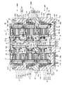
以下、本発明の実施の形態を図面を参照して説明する。図1は、本実施の形態にかかる表面磁石型の周対向ブラシレスモータを含むダイレクトドライブモータの断面図である。 Hereinafter, embodiments of the present invention will be described with reference to the drawings. FIG. 1 is a cross-sectional view of a direct drive motor including a surface magnet type circumferentially opposed brushless motor according to the present embodiment.
本実施の形態においては、表面磁石型の20極18スロットアウターロータ式ブラシレスタイプのダイレクトドライブモータを用いる。20極18スロットというスロットコンビネーションは、コギング力は小さいが径方向に磁気吸引力が発生し回転時の振動は大きいことが一般的に知られている10極9スロットというスロットコンビネーションの2倍の構成である。2n倍(nは整数)にしたことにより、径方向の磁気吸引力は相殺されるので、固定子と回転子の真円度や同軸度および機構部品の剛性を高めることなく回転時の振動を小さくでき、かつ、本来的にコギングが小さい構成であるので、非常に滑らかな回転が得られる。一方、このような多極なモータとすることにより、機械角の周期に対する電気角の周期が多いので、位置決め制御性が良い。よって、本発明の如く、減速器を用いずにロボット装置を駆動するようなダイレクトドライブモータには好適である。また、総磁束量を下げることなくステータ連結部の肉厚と突極幅、およびモータ回転子のヨーク肉厚を狭くできるので、本発明の如く、薄型かつ大径幅狭のダイレクトドライブモータには好適である。 In the present embodiment, a surface magnet type 20 pole 18 slot outer rotor brushless type direct drive motor is used. The slot combination of 20 poles and 18 slots has a configuration twice that of the slot combination of 10 poles and 9 slots, which is generally known to have a small cogging force but a large magnetic attraction force in the radial direction and a large vibration during rotation. It is. Since the magnetic attractive force in the radial direction is canceled by increasing 2n times (n is an integer), vibration during rotation without increasing the roundness and coaxiality of the stator and rotor and the rigidity of the mechanical parts Can be made small and cogging is inherently small, so that a very smooth rotation can be obtained. On the other hand, by using such a multipolar motor, the electrical angle cycle is greater than the mechanical angle cycle, so that the positioning controllability is good. Therefore, as in the present invention, it is suitable for a direct drive motor that drives a robot apparatus without using a speed reducer. In addition, since the thickness and salient pole width of the stator connecting portion and the yoke thickness of the motor rotor can be reduced without reducing the total magnetic flux, a direct drive motor having a thin and large diameter and narrow width as in the present invention can be used. Is preferred.
図1を参照して、3つのブラシレスモータBM1〜BM3を直接に連結した3軸のダイレクトドライブモータの内部構造について詳細に説明する。円盤部10aと、円盤部10aの外縁に連結された円筒部10bとからなるベース10は、円盤部10aの周囲を、定盤(不図示)に据え付けるようにして取り付けられている。円盤部10aの下面には、複数の周溝10cが形成されており、これを遮蔽するようにしてドーナツ板状の遮蔽板10dがボルトBにより取り付けられている。複数の周溝10cと遮蔽板10dとで囲われる空間は、2本のO−リングORで密封されており、かかる空間内には、遮蔽板10dに連結されたコネクタCN1から冷却液が注入され、動作時に発生した熱で加熱されたベース10の冷却が行われる。尚、熱交換が行われた冷却液は、コネクタCN2より外部に取り出される。
With reference to FIG. 1, the internal structure of a three-axis direct drive motor in which three brushless motors BM1 to BM3 are directly connected will be described in detail. A base 10 comprising a
ベース10の円盤部10aの上面に対して、円筒状の第1本体12Aがインロー嵌めにより同軸に取り付けられ、上方から挿通された長ボルトLBで固定されている。また第1本体12Aの上面には、円筒状の第2本体12Bがインロー嵌めにより同軸に取り付けられ、上方から挿通された長ボルトLBで固定されている。更に第2本体12Bの上面には、円筒状の第3本体12Cがインロー嵌めにより同軸に取り付けられ、上方から挿通された長ボルトLBで固定されている。第3本体12Cの上面には、円板12Dがインロー嵌めにより同軸に取り付けられ、ボルトBで固定されている。
A cylindrical first
薄肉円筒状の隔壁13が、ベース10の円盤部10aに下端を取り付け、円板12Dに上端を取り付けている。尚、本体12A〜12Cの中央に貫通孔を設け、ステータへの配線などを通すために用いることができる。ベース10,本体12A〜12C,円板12Dによりハウジングを構成する。
A thin
隔壁13は、非磁性体であるステンレス製であり、ベース10の円盤部10aに面当てするように放射状外側に広がった底部13aと、その内周縁から軸線方向にブラシレスモータBM1、BM2、BM3を貫くようにして延在する薄肉の円筒部13bと、円筒部13bの上縁から半径方向内方に延在するフランジ状の取付部13cとからなる。取付部13cの内方縁は、軸線方向内側に折り曲げられて短い距離だけ延在している。
The
尚、隔壁13の口元には口元つば部を嵌合することが出来、かかる場合、円筒部13bと略同一厚さの薄肉部と、円筒部13bとを軸方向のTIG溶接にて封止固定することができる。このように、溶接部を略同一厚さとすることにより、片側への部品にのみ熱が逃げることを避け、嵌合部を均一に溶接できる。口元つば部にはシール部材を填め込む溝加工を施すと好ましく、シール部材を溝に填め込んだ後にフランジにねじにて締結することにより、締結部分を大気側から分離隔絶できる。
It is to be noted that a mouth flange portion can be fitted to the mouth of the
明らかであるが、隔壁13は、ブラシレスモータBM1、BM2、BM3に共通に用いられる。隔壁13の底部13aは、ベース10の円盤部10aと、円筒部10bの内周に嵌合する環状の抑え板PT1により挟持され、ボルトBを用いて円盤部10aに固定されている。底部13aと円盤部10aとの間は、O−リングORで密封されている。又、隔壁13の取付部13cは、円板12Dと、円板状の抑え板PT2により挟持され、ボルトBを用いて円板12Dに固定されている。取付部13cと円板12Dとの間は、O−リングORで密封されている。以上により、隔壁13の締結部分を大気側から分離隔絶している。隔壁13は耐食性が高く、特に磁性の少ないオーステナイト系ステンレスのSUS316を材料としている。
As is apparent, the
更に、ベース10と定盤とは気密されているので、ベース10と隔壁13とで囲われる内部空間は、その外部(真空環境)から気密されている。尚、隔壁13は必ずしも非磁性体である必要はない。又、O−リングORを用いて気密する代わりに、電子ビーム溶接やレーザビーム溶接などで部材間を気密しても良い。
Furthermore, since the
ベース10の円筒部10bの内周段部には、真空中で用いられる背面組合せアンギュラ玉軸受19の外輪が嵌合的に取り付けられ、環状の抑え部材PT3を介して中空のボルトBにより固定されている。一方、背面組合せアンギュラ玉軸受19の内輪は、第1外側ロータ部材21のヨーク21dの外周段部に嵌合しており、上方から第1円筒状部材23により押圧されている。後述する第1アームアセンブリAA1を支持する第1円筒状部材23は、慣性低減のため、金属材料としては比重が小さいアルミニウム合金を材料とし、ヨーク21dの外径部との嵌合部と、ヨーク21dの端面との締結部を有している。第1円筒状部材23は、上部内周に、第2のブラシレスモータBM2の真空軸受装置19’の外輪を嵌合固定するための軸受ホルダ部を有している。このような構造を取ることにより、真空軸受装置19’の静止輪を隔壁12に取り付ける必要がなく、機械的な剛性を高められる。尚、第1外側ロータ部材21と第1円筒状部材23が、モータ回転子を構成する。
An outer ring of a back combination angular
ベース10は、耐食性が高いオーステナイト系ステンレスを材料としており、チャンバである定盤との嵌合固定およびシール装置を兼ねている。
The
背面組合せアンギュラ玉軸受19(真空軸受装置)は、ラジアル、アキシアル、モーメント荷重を1個の軸受で負荷できる。この形式の軸受を用いることにより、ブラシレスモータBM1のロータ支持用の軸受は1個で済むため、本発明の3軸同軸ダイレクトドライブモータを薄型化できる。背面組合せアンギュラ玉軸受19は、内外輪とも耐食性が高くかつ焼入れによる硬化が得られるマルテンサイト系ステンレスを材料とし、転動体はセラミックボール、潤滑剤は真空であっても固化しない真空用のグリスを用いている。
The back combination angular contact ball bearing 19 (vacuum bearing device) can carry radial, axial and moment loads with a single bearing. By using this type of bearing, since only one bearing for supporting the rotor of the brushless motor BM1 is required, the triaxial coaxial direct drive motor of the present invention can be thinned. The back combination angular
尚、背面組合せアンギュラ玉軸受19は内輪と外輪に金や銀などの軟質金属をプレーティングして、真空中でもアウトガス放出のない金属潤滑としたものを用いてもよく、また後述するアームアッセンブリからの第1外側ロータ部材21がチルトする方向のモーメントを受けることができるが、これに限らず、クロスローラ、クロスボール、クロステーパ軸受も用いることができ、予圧状態で用いても良いし、潤滑性向上のためフッ素系被膜処理(DFO)を行っても良い。
The back combination angular
第1外側ロータ部材21は、磁石ホルダ21aによって保持された永久磁石21b及び真空カップリング磁石21cと、磁路を形成するため磁性体から成る円環状のヨーク21dとによって構成されている。
The first
永久磁石21bは極ごとに分割されたセグメント形式であり、エネルギー積の高いネオジウム(Nd−Fe−B)系磁石を材料としている。このネオジウム系磁石は、鉄と比較して線膨張係数が非常に小さい上にもろく割れやすい性質を持つ。本実施の形態においては、耐食性を高め、かつ、耐磨耗性の高いニッケルコーティングを施してある。このような表面処理を施すことにより、不純分子を吸蔵しにくく、かつ、後述する磁石ホルダ21aで固定する際のすべりや、極度の高温または低温時にさらされた際の、摺動磨耗による発塵を防げるので真空環境に好適である、その個々の形状は略分割円環状である。
The
永久磁石21bのヨーク21dと接する外径側の形状は、後述するヨーク21dの内周と同一半径ないし若干大きい半径を有する円弧状である。又、永久磁石21bのエアギャップ側である内周側の形状は、ヨーク21dに配置された際に、各々の永久磁石21bの円弧中心が回転中心と同一となるような半径を有する円弧状である。更に、永久磁石21bの円周方向端面の形状は直線状であり、円周方向端面においては、後述する第1ステータ29と対向する側が狭く、ヨーク21dと接する側が広い略台形状であり、軸方向端面は直線状であるが、軸線に対して直角である。尚、永久磁石21bの各辺は面取りが施してあり、微細な割れや欠けを防いでいる。軸方向の長さは第1ステータ29の長さと同じか、やや長く設定し、トルク不足を防止することが望ましい。
The shape of the outer diameter side in contact with the
一方、真空カップリング磁石21cは、一つの磁石の面に3極(N−S−N又はS−N−S)着磁したタイプであって、エネルギー積の高いネオジウム(Nd−Fe−B)系磁石を材料としている。このネオジウム系磁石は、鉄と比較して線膨張係数が非常に小さい上にもろく割れやすい性質を持つ。本実施の形態においては、耐食性を高め、かつ、耐磨耗性の高いニッケルコーティングを施してある。このような表面処理を施すことにより、不純分子を吸蔵しにくく、かつ、後述する磁石ホルダ21aで固定する際のすべりや、極度の高温または低湿時にさらされた際の、摺動磨耗による発塵を防げるので真空環境に好適である。その個々の形状は略分割円環状である。
On the other hand, the
真空カップリング磁石21cのヨーク21dと接する外径側の形状は、後述するヨーク21dの内周と同一半径ないし若干大きい半径を有する円弧状である。又、真空カップリング磁石21cのエアギャップ側である内周側の形状は、ヨーク21dに配置された際に、各々の永久磁石21bの円弧中心が回転中心と同一となるような半径を有する円弧状である。更に、真空カップリング磁石21cの円周方向端面の形状は直線状であり、円周方向端面においては、後述する大気カップリング磁石30と対向する側が狭く、ヨーク21dと接する側が広い略台形状であり、軸方向端面は直線状であるが、軸線に対して直角である。尚、真空カップリング磁石21cの各辺は面取りが施してあり、微細な割れや欠けを防いでいる。軸方向の長さは後述する大気カップリング磁石30aの長さと同じか、やや長く設定し、トルク不足を防止することが望ましい。
The shape of the
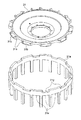
図10に、磁石ホルダ21aとロータホルダ31の斜視図を示す。磁石ホルダ21aは、磁束が短絡して第1ステータ29への鎖交磁束が低減することを防ぐため、非磁性材料で作られ、永久磁石21b及び真空カップリング磁石21cがヨーク21dから外れること防ぐ機能を有する。特に、この材料に非磁性ステンレスを使用した場合には、耐食性が高いので不純分子を吸蔵しにくく、真空環境に好適に使用されている。
FIG. 10 shows a perspective view of the
軸方向における磁石ホルダ21aの両端面には、均等に永久磁石21b及び真空カップリング磁石21cの固定用溝(切欠)21x、21yを櫛歯状に有し、円筒の外径はヨーク21dの内径と、しまり嵌めの関係になることよって、永久磁石21b及び真空カップリング磁石21cを円周上で精度良く均等に配置でき、これによりコキングトルクの低減や磁気カップリング剛性向上の効果が得られる。
On both end surfaces of the
永久磁石21bを保持する溝21xと真空カップリング磁石21cを保持する溝21yは互いに独立し、必要なモータトルクと磁気カップリングの性能に従って、永久磁石21b及び真空カップリング磁石21cを独立に設定できる。
The
本実施の形態の磁石ホルダ21aは、永久磁石21bの固定用溝21xが20個、真空カップリング磁石21cの固定用溝21yが10個で構成されている。
The
1つの磁石片は1つの溝21x、21yと嵌めあい、各溝21x、21yの側面は軸方向とほぼ平行し、かつ、円周方向において、永久磁石21b及び真空カップリング磁石21cの側面の傾きに倣って、平行かつ隙間を有する形状である。また、この隙間は永久磁石21b及び真空カップリング磁石21cがエアギャップ方向に浮いたとしても、第1ステータ29との吸着力より、ヨーク21dとの吸着力の方が強く、かつ、モータの使用温度および保存温度の低温側にさらされた際でも隙間が残留する寸法である。
One magnet piece fits into one
ヨーク21dは、高い磁性を有する低炭素鋼を材料とし、加工成形後に防錆および耐食性を高め、かつ軸受交換時の磨耗を防ぐためにニッケルめっきを施している。その形状は略円環状である。
The
図1において、永久磁石21b及び真空カップリング磁石21cを配置する内径部には、止め輪21eを配置する溝21fを両端に設置し、両端の止め輪溝21f間距離は、永久磁石21b長さ+磁石ホルダ21aの間座部長さ+真空カップリング磁石21c長さより若干幅広である。
In FIG. 1, a
両端の止め輪溝21f間距離と、永久磁石21b長さ+磁石ホルダ21aの間座部長さ+真空カップリング磁石21c長さとの差は、モータの使用温度および保存温度の低温側にさらされた際でも隙間が残留する寸法である。
The difference between the distance between the retaining
ヨーク21dの外径側には、背面組合せアンギュラ玉軸受19の内輪に嵌合固定する段部を有しており、互いに嵌合する構造となっている。本実施の形態の場合は、真空用グリス潤滑の背面組合せアンギュラ玉軸受19を用いているので、回転輪である内輪を、加工精度を出しやすくかつ線膨張係数が軸受の軌道輪材質と略同一であるヨークに対して締まり嵌めあるいは中間嵌めとし、固定輪である外輪を真空環境で頻繁に用いられるアルミニウムやオーステナイト系ステンレス製のベース10の円筒部10bに対してすきま嵌めとすることで、背面組合せアンギュラ玉軸受19の回転精度の低下や温度上昇による摩擦トルクの上昇を防ぐ構成となっている。
On the outer diameter side of the
本実施の形態では、トルク発生機能を持つ永久磁石21bと磁気カップリング吸引機能を持つ真空カップリング磁石21cは、磁石ホルダ21aにより、分離されているが、永久磁石21b及び真空カップリング磁石21cを必ず分ける必要がなく、トルク発生と磁気カップリング吸引力の発生源を一つの磁石にまとめ、適切な固定方法より固定することも可能である。
In the present embodiment, the
永久磁石21bを磁石ホルダ21dに組入れた後、軸方向における永久磁石21bの上下運動を拘束するために、非磁性ステンレスで作られた2重止め輪21eをヨーク21dの両端にある止め輪用溝21fにいれて、永久磁石21bを固定する。
After the
磁石ホルダ21dを固定するボルト(不図示)は、ヨーク21dと同様に高い磁性を有する低炭素鋼を材料とし、加工成形後に防錆および耐食性を高め、かつ軸受交換時の磨耗を防ぐためにニッケルめっきを施している。
The bolt (not shown) for fixing the
隔壁13の半径方向内側において、第1外側ロータ部材21の内周面に対向するようにして、第1ステータ29が配置されている。第1ステータ29は、第1本体12Aの下端から半径方向に延在したフランジ部12aの円筒状外周部に取り付けられており、電磁鋼板の積層材で形成され、各突極には絶縁処理としてボビンを嵌め込んだ後にモータコイルが集中巻されている。第1ステータ29の外径は隔壁13の内径と略同一もしくは小さい寸法としている。
A
第1ステータ29に隣接且つ平行して、第1内側ロータ30が配置されている。第1内側ロータ30は、ロータホルダ31の外周に固定され、第1本体12Aに対して、玉軸受33を介して回転自在に支持されている。
A first
第1内側ロータ30は、ロータホルダ31の外周に等間隔に形成された凹部内に配置される永久磁石30aと、永久磁石30aの背面に装着され磁路を形成するための磁性体から成る板状のバックヨーク30bとからなる。永久磁石30aは、30極の構成でS極−N極−S極又はN極−S極−N極の磁石が各10個交互に磁性金属からなっている。従って、第1内側ロータ30は、磁気カップリング作用により、第1ステータ29によって駆動される第1外側ロータ部材21に同期して連れ回されるようになっている。バックヨーク30bは、高い磁性を有する低炭素鋼を材料とし,加工成形後に防錆のためにクロメートめっきを施している。
The first
永久磁石30aのエアギャップ側の外周側の形状は、隔壁13の内径より若干小さい半径を有する円弧状であり、軸方向において、回転軸と平行である。永久磁石30aの回転軸中心側の形状は平面であり、軸方向において、回転軸と平行になる。永久磁石30aの円周方向端面の形状は直線状であり、円周方向端面においては真空側と対向する側が狭く、回転軸中心側が広い略台形状であり、軸方向端面は直線状であるが、軸線に対して直角である。永久磁石30aの各辺は面取りが施してあり、微細な割れや欠けを防いでいる。軸方向長さは大気側カップリング磁石とほぼ同じに設定する。
The shape of the outer peripheral side of the air gap side of the
ロータホルダ31は、図10に示すごとく花の形状のように、円周方向に沿って外周側に永久磁石30aの固定部31aがあり、各固定部31aは永久磁石30aと同極数で配置されている。各固定部には永久磁石30aと嵌めあう台形凹部31bが設置されている。各凹部31bの側面は軸方向とほぼ平行し、かつ、円周方向において、ここに組み付けられる永久磁石30aの側面の傾きに倣って、平行かつ隙間を有する形状である。また、この隙間は永久磁石30aがエアギャップ方向に浮いたとしても、位置決めキーとの吸着力よりヨーク21dとの吸着力の方が強く、かつ、モータの使用温度および保存温度の低温側にさらされた際でも隙間が残留する寸法である。永久磁石30aの軸方向運動を拘束するために、2液エポキシ接着剤を使って永久磁石30aを第1内側ロータ30に固定することより、高信頼性のモータを提供することができる。
As shown in FIG. 10, the
モータ軸方向において、大気側の永久磁石30aと真空側カップリング磁石21cの中心をずらして設置することによって、永久磁石30aに軸方向下向きの吸引力を作用させることができ、これにより第1内側ロータ30を介して、軸受装置33にアキシアル荷重が伝達され、適切な予圧効果を与えることができる。これによって、高精度な回転ができ、正確な位置検出ができる。
In the motor axial direction, the center of the atmospheric-side
第1内側ロータ30を回転自在に支持する軸受33は、ラジアル、アキシアル、モーメント荷重を負荷できる二つの深溝玉軸受からなる。隔壁13の内部は大気環境であるため、一般的な軸受鋼と鉱油を基油としたグリス潤滑を用いた軸受を適用できる。
The bearing 33 that rotatably supports the first
隔壁13内部は大気環境であるため、永久磁石30aはバックヨーク30bに接着固定してある。永久磁石30aはエネルギー積の高いネオジウム(Nd−Fe−B)系磁石であり、錆による減磁を防ぐためにニッケルコーティングを施してある。バックヨーク30bは高い磁性を有する低炭素鋼を材料とし、加工成形後に防錆のためにクロメートめっきを施している。
Since the inside of the
図1において、第1内側ロータ30を取り付けたロータホルダ31の内周は、回転角度を計測する検出器として、レゾルバロータ34a及び34bを保持してなる回転筒34cに組みつけられている。ロータホルダ31の内周を保持する回転筒34cは、軸受33により回転自在に支持されている。レゾルバロータ34a及び34bに対向する形で、第1本体12Aの外周に、レゾルバステータ35,36を取り付けているが、本実施の形態では、高分解能のインクリメンタルレゾルバステータ35と、1回転のいずれの位置にロータがあるかを検出できるアブソリュートレゾルバステータ36とを2層に配置している。これによりアブソリュートレゾルバからの絶対角度情報に基づき,電源投入直後の回転子機械角の認識と,モータコイルへのコンミテーションを行っている。一方,インクリメンタルレゾルバからの相対角度情報に基づき,高分解能の角度位置決め動作を行っている。このため電源投入時にも、アブソリュートレゾルバロータ34bの回転角度がわかり、原点復帰が不要であり、また、コイルに対する磁石の電気的位相角度がわかるため、ブラシレスモータBM1の駆動電流制御に使用する回転角度検出が、極検出センサを用いることなく可能となっている。このため、本実施の形態の如く,スカラーロボットを駆動するようなダイレクトドライブモータには好適である。
In FIG. 1, the inner periphery of the
本実施の形態に用いている高分解能の可変リラクタンス形レゾルバにおいて、インクリメンタルレゾルバロータ34aは、一定のピッチを有する複数のスロツト歯列を有し、インクリメンタルレゾルバステータ35の外周面には、回転軸と平行に各磁極でインクリメンタルレゾルバロータ34aに対して位相をずらした歯が設けられており、コイルが各磁極に巻回されている。軸受33により支持された第1内側ロータ30と一体でインクリメンタルレゾルバロータ34aが回転すると、インクリメンタルレゾルバステータ35の磁極との間のリラクタンスが変化し、インクリメンタルレゾルバロータ34aの1回転でリラクタンス変化の基本波成分がn周期となるようにして、そのリラクタンス変化を検出して、図2に例を示すレゾルバ制御回路によりデジタル化し、位置信号として利用することでインクリメンタルレゾルバロータ34a即ち第1内側ロータ30の回転角度(又は回転速度)を検出するようになっている。レゾルバロータ34a、34bと、レゾルバステータ35,36とで検出器を構成する。
In the high-resolution variable reluctance resolver used in the present embodiment, the
本実施の形態によれば、第1外側ロータ部材21に対して、磁気カップリング作用により第1内側ロータ30が同速で回転し、すなわち連れ回るので、第1外側ロータ部材21の回転角を隔壁13越しに検出することができる。また、本実施の形態では、モータを形成する部品やハウジングを用いることなくレゾルバ単体で軸受33を有しており、従ってハウジングに組み込む前に、レゾルバ単体での偏芯調整やレゾルバコイルの位置調整などの精度調整が行えるので、ハウジングや両フランジに調整用の穴や切り欠きを別途設ける必要がない。
According to the present embodiment, the first
次に、ブラシレスモータBM2について説明するが、ここでは第2本体12Bがハウジングを構成する。上述したブラシレスモータBM1の一部となる第1円筒状部材23は、ブラシレスモータBM2の上端近くまで上方に延在しており、その内周段部に、真空中で用いられる複列の背面組合せアンギュラ玉軸受19’の外輪が嵌合的に取り付けられ、環状の抑え部材PT4を介して中空のボルトBにより固定されている。一方、背面組合せアンギュラ玉軸受19’の内輪は、第2外側ロータ部材21’のヨーク21d’の外周段部に嵌合しており、上方から第2円筒状部材23’により押圧されている。第2円筒状部材23’の下端は二重円筒状になっており、その間に第1円筒状部材23の上端が入り込む形となっている。又、第2円筒状部材23’の外周には、後述する第11ベルトBL11が巻き付く第1レース面23a’と、第21ベルトBL21が巻き付く第1レース面23b’が軸線方向に離して設けられている。第2円筒状部材23’は、慣性低減のため、金属材料としては比重が小さいアルミニウム合金を材料とし、ヨーク21d’の外径部との嵌合部と、ヨーク21d’の端面との締結部を有している。第2外側ロータ部材21’は、第2円筒状部材23’と一体的に、隔壁13に対して回転自在に支持されている。尚、第2外側ロータ部材21’が、外側ロータを構成する。
Next, the brushless motor BM2 will be described. Here, the second
背面組合せアンギュラ玉軸受19’(真空軸受装置)は、ラジアル、アキシアル、モーメント荷重を1個の軸受で負荷できる。この形式の軸受を用いることにより、ブラシレスモータBM2のロータ支持用の軸受は1個で済むため、本発明の3軸同軸ダイレクトドライブモータを薄型化できる。背面組合せアンギュラ玉軸受19’は、内外輪とも耐食性が高くかつ焼入れによる硬化が得られるマルテンサイト系ステンレスを材料とし、転動体はセラミックボール、潤滑剤は真空であっても固化しない真空用のグリスを用いている。 The back combination angular contact ball bearing 19 '(vacuum bearing device) can carry radial, axial and moment loads with a single bearing. By using this type of bearing, only one bearing for supporting the rotor of the brushless motor BM2 is required, so that the triaxial coaxial direct drive motor of the present invention can be made thinner. The back combined angular contact ball bearing 19 'is made of martensitic stainless steel, which has high corrosion resistance for both the inner and outer rings and can be hardened by quenching. The rolling element is a ceramic ball, and the lubricant is vacuum grease that does not solidify even under vacuum. Is used.
尚、背面組合せアンギュラ玉軸受19’は内輪と外輪に金や銀などの軟質金属をプレーティングして、真空中でもアウトガス放出のない金属潤滑としたものを用いてもよく、また後述するアームアッセンブリからの第2外側ロータ部材21’がチルトする方向のモーメントを受けることができるが、これに限らず、クロスローラ、クロスボール、クロステーパ軸受も用いることができ、予圧状態で用いても良いし、潤滑性向上のためフッ素系被膜処理(DFO)を行っても良い。
The back combination angular contact ball bearing 19 'may be made by plating a soft metal such as gold or silver on the inner ring and the outer ring to obtain metal lubrication that does not release outgas even in a vacuum, or from an arm assembly described later. The second
第2外側ロータ部材21’は、磁石ホルダ21a’によって保持された永久磁石21b’及び真空カップリング磁石21c’と、磁路を形成するため磁性体から成る円環状のヨーク21d’とによって構成されている。
The second
永久磁石21b’は極ごとに分割されたセグメント形式であり、エネルギー積の高いネオジウム(Nd−Fe−B)系磁石を材料としている。このネオジウム系磁石は、鉄と比較して線膨張係数が非常に小さい上にもろく割れやすい性質を持つ。本実施の形態においては、耐食性を高め、かつ、耐磨耗性の高いニッケルコーティングを施してある。このような表面処理を施すことにより、不純分子を吸蔵しにくく、かつ、後述する磁石ホルダ21a’で固定する際のすべりや、極度の高温または低温時にさらされた際の、摺動磨耗による発塵を防げるので真空環境に好適である、その個々の形状は略分割円環状である。
The
永久磁石21b’のヨーク21d’と接する外径側の形状は、後述するヨーク21d’の内周と同一半径ないし若干大きい半径を有する円弧状である。又、永久磁石21b’のエアギャップ側である内周側の形状は、ヨーク21d’に配置された際に、各々の永久磁石21b’の円弧中心が回転中心と同一となるような半径を有する円弧状である。更に、永久磁石21b’の円周方向端面の形状は直線状であり、円周方向端面においては、後述する第2ステータ29’と対向する側が狭く、ヨーク21d’と接する側が広い略台形状であり、軸方向端面は直線状であるが、軸線に対して直角である。尚、永久磁石21b’の各辺は面取りが施してあり、微細な割れや欠けを防いでいる。軸方向の長さは第2ステータ29’の長さと同じか、やや長く設定し、トルク不足を防止することが望ましい。
The shape of the
一方、真空カップリング磁石21c’は、一つの磁石の面に3極(N−S−N又はS−N−S)着磁したタイプであって、エネルギー積の高いネオジウム(Nd−Fe−B)系磁石を材料としている。このネオジウム系磁石は、鉄と比較して線膨張係数が非常に小さい上にもろく割れやすい性質を持つ。本実施の形態においては、耐食性を高め、かつ、耐磨耗性の高いニッケルコーティングを施してある。このような表面処理を施すことにより、不純分子を吸蔵しにくく、かつ、後述する磁石ホルダ21a’で固定する際のすべりや、極度の高温または低湿時にさらされた際の、摺動磨耗による発塵を防げるので真空環境に好適である。その個々の形状は略分割円環状である。
On the other hand, the
真空カップリング磁石21c’のヨーク21d’と接する外径側の形状は、後述するヨーク21d’の内周と同一半径ないし若干大きい半径を有する円弧状である。又、真空カップリング磁石21c’のエアギャップ側である内周側の形状は、ヨーク21d’に配置された際に、各々の永久磁石21b’の円弧中心が回転中心と同一となるような半径を有する円弧状である。更に、真空カップリング磁石21c’の円周方向端面の形状は直線状であり、円周方向端面においては、後述する大気カップリング磁石30’と対向する側が狭く、ヨーク21d’と接する側が広い略台形状であり、軸方向端面は直線状であるが、軸線に対して直角である。尚、真空カップリング磁石21c’の各辺は面取りが施してあり、微細な割れや欠けを防いでいる。軸方向の長さは後述する大気カップリング磁石30a’の長さと同じか、やや長く設定し、トルク不足を防止することが望ましい。
The shape of the outer diameter side of the
磁石ホルダ21a’は、磁束が短絡して第2ステータ29’への鎖交磁束が低減することを防ぐため、非磁性材料で作られ、永久磁石21b’及び真空カップリング磁石21c’がヨーク21d’から外れること防ぐ機能を有する。特に、この材料に非磁性ステンレスを使用した場合には、耐食性が高いので不純分子を吸蔵しにくく、真空環境に好適に使用されている。
The
図10に示すものと同様に、軸方向における磁石ホルダ21a’の両端面には、均等に永久磁石21b’及び真空カップリング磁石21c’の固定用溝(切欠)を櫛歯状に有し、円筒の外径はヨーク21d’の内径と、しまり嵌めの関係になることよって、永久磁石21b’及び真空カップリング磁石21c’を円周上で精度良く均等に配置でき、これによりコキングトルクの低減や磁気カップリング剛性向上の効果が得られる。
Similar to the one shown in FIG. 10, the fixing grooves (notches) for the
永久磁石21b’を保持する溝と真空カップリング磁石21c’を保持する溝は互いに独立し、必要なモータトルクと磁気カップリングの性能に従って、永久磁石21b’及び真空カップリング磁石21c’を独立に設定できる。
The groove for holding the
本実施の形態の磁石ホルダ21a’は、永久磁石21b’の固定用溝が20個、真空カップリング磁石21c’の固定用溝10個で構成されている。
The
1つの磁石片は1つの溝と嵌めあい、各溝の側面は軸方向とほぼ平行し、かつ、円周方向において、永久磁石21b’及び真空カップリング磁石21c’の側面の傾きに倣って、平行かつ隙間を有する形状である。また、この隙間は永久磁石21b’及び真空カップリング磁石21c’がエアギャップ方向に浮いたとしても、第2ステータ29’との吸着力より、ヨーク21d’との吸着力の方が強く、かつ、モータの使用温度および保存温度の低温側にさらされた際でも隙間が残留する寸法である。
One magnet piece fits into one groove, the side surface of each groove is substantially parallel to the axial direction, and follows the inclination of the side surfaces of the
ヨーク21d’は、高い磁性を有する低炭素鋼を材料とし、加工成形後に防錆および耐食性を高め、かつ軸受交換時の磨耗を防ぐためにニッケルめっきを施している。その形状は略円環状である。
The
永久磁石21b’及び真空カップリング磁石21c’を配置する内径部には、止め輪21e’を配置する溝21f’を両端に設置し、両端の止め輪溝21f’間距離は、永久磁石21b’長さ+磁石ホルダ21a’の間座部長さ+真空カップリング磁石21c’長さより若干幅広である。
両端の止め輪溝21f’間距離と、永久磁石21b’長さ+磁石ホルダ21a’の間座部長さ+真空カップリング磁石21c’長さとの差は、モータの使用温度および保存温度の低温側にさらされた際でも隙間が残留する寸法である。
The difference between the distance between the retaining
ヨーク21d’の外径側には、背面組合せアンギュラ玉軸受19’の内輪に嵌合固定する段部を有しており、互いに嵌合する構造となっている。本実施の形態の場合は、真空用グリス潤滑の背面組合せアンギュラ玉軸受19’を用いているので、内輪を、加工精度を出しやすくかつ線膨張係数が軸受の軌道輪材質と略同一であるヨークに対して締まり嵌めあるいは中間嵌めとし、外輪を第1円筒状部材23に対してすきま嵌めとすることで、背面組合せアンギュラ玉軸受19’の回転精度の低下や温度上昇による摩擦トルクの上昇を防ぐ構成となっている。
On the outer diameter side of the
本実施の形態では、トルク発生機能を持つ永久磁石21b’と磁気カップリング吸引機能を持つ真空カップリング磁石21c’は、磁石ホルダ21a’により、分離されているが、永久磁石21b’及び真空カップリング磁石21c’を必ず分ける必要がなく、トルク発生と磁気カップリング吸引力の発生源を一つの磁石にまとめ、適切な固定方法より固定することも可能である。
In the present embodiment, the
永久磁石21b’を磁石ホルダ21d’に組入れた後、軸方向における永久磁石21b’の上下運動を拘束するために、非磁性ステンレスで作られた2重止め輪21e’をヨーク21d’の両端にある止め輪用溝21f’にいれて、永久磁石21b’を固定する。
After the
磁石ホルダ21d’を固定するボルト(不図示)は、ヨーク21d’と同様に高い磁性を有する低炭素鋼を材料とし、加工成形後に防錆および耐食性を高め、かつ軸受交換時の磨耗を防ぐためにニッケルめっきを施している。
The bolt (not shown) for fixing the
隔壁13の半径方向内側において、第2外側ロータ部材21’の内周面に対向するようにして、第2ステータ29’が配置されている。第2ステータ29’は、第2本体12Bの下端から半径方向に延在したフランジ部12bの円筒状外周部に取り付けられており、電磁鋼板の積層材で形成され、各突極には絶縁処理としてボビンを嵌め込んだ後にモータコイルが集中巻されている。第2ステータ29’の外径は隔壁13の内径と略同一もしくは小さい寸法としている。
A
第2ステータ29’に隣接且つ平行して、第2内側ロータ30’が配置されている。第2内側ロータ30’は、ロータホルダ31’の外周に固定され、第2本体12Bに対して、玉軸受33’を介して回転自在に支持されている。
A second inner rotor 30 'is disposed adjacent to and parallel to the second stator 29'. The second
第2内側ロータ30’は、ロータホルダ31’の外周に等間隔に形成された凹部内に配置される永久磁石30a’と、永久磁石30a’の背面に装着され磁路を形成するための磁性体から成る板状のバックヨーク30b’とからなる。永久磁石30a’は、30極の構成でS極−N極−S極又はN極−S極−N極の磁石が各10個交互に磁性金属からなっている。従って、第2内側ロータ30’は、磁気カップリング作用により、第2ステータ29’によって駆動される第2外側ロータ部材21’に同期して連れ回されるようになっている。バックヨーク30b’は、高い磁性を有する低炭素鋼を材料とし,加工成形後に防錆のためにクロメートめっきを施している。
The second
永久磁石30a’のエアギャップ側の外周側の形状は、隔壁13の内径より若干小さい半径を有する円弧状であり、軸方向において、回転軸と平行である。永久磁石30a’の回転軸中心側の形状は平面であり、軸方向において、回転軸と平行になる。永久磁石30a’の円周方向端面の形状は直線状であり、円周方向端面においては真空側と対向する側が狭く、回転軸中心側が広い略台形状であり、軸方向端面は直線状であるが、軸線に対して直角である。永久磁石30a’の各辺は面取りが施してあり、微細な割れや欠けを防いでいる。軸方向長さは大気側カップリング磁石とほぼ同じに設定する。
The shape of the outer peripheral side of the air gap side of the
ロータホルダ31’は、図10を参照して、花の形状のように、円周方向に沿って外周側に永久磁石30a’の固定部があり、各固定部は永久磁石30a’と同極数で配置されている。各固定部には永久磁石30a’と嵌めあう台形凹部が設置されている。各凹部の側面は軸方向とほぼ平行し、かつ、円周方向において、ここに組み付けられる永久磁石30a’の側面の傾きに倣って、平行かつ隙間を有する形状である。また、この隙間は永久磁石30a’がエアギャップ方向に浮いたとしても、位置決めキーとの吸着力よりヨーク21d’との吸着力の方が強く、かつ、モータの使用温度および保存温度の低温側にさらされた際でも隙間が残留する寸法である。永久磁石30a’の軸方向運動を拘束するために、2液エポキシ接着剤を使って永久磁石30a’を第2内側ロータ30’に固定することより、高信頼性のモータを提供することができる。
Referring to FIG. 10, the
モータ軸方向において、大気側の永久磁石30a’と真空側カップリング磁石21c’の中心をずらして設置することによって、永久磁石30a’に軸方向下向きの吸引力を作用させることができ、これにより第2内側ロータ30’を介して、軸受装置33’にアキシアル荷重が伝達され、適切な予圧効果を与えることができる。これによって、高精度な回転ができ、正確な位置検出ができる。
In the motor axial direction, by placing the center of the atmospheric
第2内側ロータ30’を回転自在に支持する軸受33’は、ラジアル、アキシアル、モーメント荷重を負荷できる二つの深溝玉軸受からなる。隔壁13の内部は大気環境であるため、一般的な軸受鋼と鉱油を基油としたグリス潤滑を用いた軸受を適用できる。
The bearing 33 ′ that rotatably supports the second
隔壁13内部は大気環境であるため、永久磁石30a’はバックヨーク30b’に接着固定してある。永久磁石30a’はエネルギー積の高いネオジウム(Nd−Fe−B)系磁石であり、錆による減磁を防ぐためにニッケルコーティングを施してある。バックヨーク30b’は高い磁性を有する低炭素鋼を材料とし、加工成形後に防錆のためにクロメートめっきを施している。
Since the inside of the
図1において、第2内側ロータ30’を取り付けたロータホルダ31’の内周は、回転角度を計測する検出器として、レゾルバロータ34a’及び34b’を保持してなる回転筒34c’に組みつけられている。ロータホルダ31’の内周を保持する回転筒34c’は、軸受33’により回転自在に支持されている。レゾルバロータ34a’及び34b’に対向する形で、第2本体12Bの外周に、レゾルバステータ35’,36’を取り付けているが、本実施の形態では、高分解能のインクリメンタルレゾルバステータ35’と、1回転のいずれの位置にロータがあるかを検出できるアブソリュートレゾルバステータ36’とを2層に配置している。これによりアブソリュートレゾルバからの絶対角度情報に基づき,電源投入直後の回転子機械角の認識と,モータコイルへのコンミテーションを行っている。一方,インクリメンタルレゾルバからの相対角度情報に基づき,高分解能の角度位置決め動作を行っている。このため電源投入時にも、アブソリュートレゾルバロータ34b’の回転角度がわかり、原点復帰が不要であり、また、コイルに対する磁石の電気的位相角度がわかるため、ブラシレスモータBM2の駆動電流制御に使用する回転角度検出が、極検出センサを用いることなく可能となっている。このため、本実施の形態の如く,スカラーロボットを駆動するようなダイレクトドライブモータには好適である。
In FIG. 1, the inner circumference of the
本実施の形態に用いている高分解能の可変リラクタンス形レゾルバにおいて、インクリメンタルレゾルバロータ34a’は、一定のピッチを有する複数のスロツト歯列を有し、インクリメンタルレゾルバステータ35’の外周面には、回転軸と平行に各磁極でインクリメンタルレゾルバロータ34a’に対して位相をずらした歯が設けられており、コイルが各磁極に巻回されている。軸受33’により支持された第2内側ロータ30’と一体でインクリメンタルレゾルバロータ34a’が回転すると、インクリメンタルレゾルバステータ35’の磁極との間のリラクタンスが変化し、インクリメンタルレゾルバロータ34a’の1回転でリラクタンス変化の基本波成分がn周期となるようにして、そのリラクタンス変化を検出して、図2に例を示すレゾルバ制御回路によりデジタル化し、位置信号として利用することでインクリメンタルレゾルバロータ34a’即ち第2内側ロータ30’の回転角度(又は回転速度)を検出するようになっている。レゾルバロータ34a’、34b’と、レゾルバステータ35’,36’とで検出器を構成する。
In the high-resolution variable reluctance resolver used in the present embodiment, the
本実施の形態によれば、第2外側ロータ部材21’に対して、磁気カップリング作用により第2内側ロータ30’が同速で回転し、すなわち連れ回るので、第2外側ロータ部材21’の回転角を隔壁13越しに検出することができる。また、本実施の形態では、モータを形成する部品やハウジングを用いることなくレゾルバ単体で軸受33’を有しており、従ってハウジングに組み込む前に、レゾルバ単体での偏芯調整やレゾルバコイルの位置調整などの精度調整が行えるので、ハウジングや両フランジに調整用の穴や切り欠きを別途設ける必要がない。
According to the present embodiment, the second
次に、ブラシレスモータBM3について説明するが、ここでは第3本体12Cがハウジングを構成する。上述したブラシレスモータBM2の一部となる第2円筒状部材23’は、ブラシレスモータBM3の上端まで上方に延在しており、その内周段部に、真空中で用いられる複列の背面組合せアンギュラ玉軸受19”の外輪が嵌合的に取り付けられ、環状の抑え部材PT5を介して不図示のボルトにより固定されている。一方、背面組合せアンギュラ玉軸受19”の内輪は、第3外側ロータ部材21”のヨーク21d”の外周段部に嵌合しており、上方から第3円筒状部材23”により押圧されている。第3外側ロータ部材21”は、第3円筒状部材23”と一体的に、隔壁13に対して回転自在に支持されている。後述する第2アームアセンブリAA2を支持する第3円筒状部材23”は、慣性低減のため、金属材料としては比重が小さいアルミニウム合金を材料とし、ヨーク21d”の外径部との嵌合部と、ヨーク21d”の端面との締結部を有している。第3外側ロータ部材21”は、第3円筒状部材23”と一体的に、隔壁13に対して回転自在に支持されている。尚、第3外側ロータ部材21”と第3円筒状部材23”が、モータ回転子を構成する。
Next, the brushless motor BM3 will be described. Here, the third
背面組合せアンギュラ玉軸受19”(真空軸受装置)は、ラジアル、アキシアル、モーメント荷重を1個の軸受で負荷できる。この形式の軸受を用いることにより、ブラシレスモータBM3のロータ支持用の軸受は1個で済むため、本発明の3軸同軸ダイレクトドライブモータを薄型化できる。背面組合せアンギュラ玉軸受19”は、内外輪とも耐食性が高くかつ焼入れによる硬化が得られるマルテンサイト系ステンレスを材料とし、転動体はセラミックボール、潤滑剤は真空であっても固化しない真空用のグリスを用いている。
The back combination angular
尚、背面組合せアンギュラ玉軸受19”は内輪と外輪に金や銀などの軟質金属をプレーティングして、真空中でもアウトガス放出のない金属潤滑としたものを用いてもよく、また後述するアームアッセンブリからの第3外側ロータ部材21”がチルトする方向のモーメントを受けることができるが、これに限らず、クロスローラ、クロスボール、クロステーパ軸受も用いることができ、予圧状態で用いても良いし、潤滑性向上のためフッ素系被膜処理(DFO)を行っても良い。
The back combination angular
第3外側ロータ部材21”は、磁石ホルダ21a”によって保持された永久磁石21b”及び真空カップリング磁石21c”と、磁路を形成するため磁性体から成る円環状のヨーク21d”とによって構成されている。
The third
永久磁石21b”は極ごとに分割されたセグメント形式であり、エネルギー積の高いネオジウム(Nd−Fe−B)系磁石を材料としている。このネオジウム系磁石は、鉄と比較して線膨張係数が非常に小さい上にもろく割れやすい性質を持つ。本実施の形態においては、耐食性を高め、かつ、耐磨耗性の高いニッケルコーティングを施してある。このような表面処理を施すことにより、不純分子を吸蔵しにくく、かつ、後述する磁石ホルダ21a”で固定する際のすべりや、極度の高温または低温時にさらされた際の、摺動磨耗による発塵を防げるので真空環境に好適である、その個々の形状は略分割円環状である。
The
永久磁石21b”のヨーク21d”と接する外径側の形状は、後述するヨーク21d”の内周と同一半径ないし若干大きい半径を有する円弧状である。又、永久磁石21b”のエアギャップ側である内周側の形状は、ヨーク21d”に配置された際に、各々の永久磁石21b”の円弧中心が回転中心と同一となるような半径を有する円弧状である。更に、永久磁石21b”の円周方向端面の形状は直線状であり、円周方向端面においては、後述する第3ステータ29”と対向する側が狭く、ヨーク21d”と接する側が広い略台形状であり、軸方向端面は直線状であるが、軸線に対して直角である。尚、永久磁石21b”の各辺は面取りが施してあり、微細な割れや欠けを防いでいる。軸方向の長さは第3ステータ29”の長さと同じか、やや長く設定し、トルク不足を防止することが望ましい。
The shape of the
一方、真空カップリング磁石21c”は、一つの磁石の面に3極(N−S−N又はS−N−S)着磁したタイプであって、エネルギー積の高いネオジウム(Nd−Fe−B)系磁石を材料としている。このネオジウム系磁石は、鉄と比較して線膨張係数が非常に小さい上にもろく割れやすい性質を持つ。本実施の形態においては、耐食性を高め、かつ、耐磨耗性の高いニッケルコーティングを施してある。このような表面処理を施すことにより、不純分子を吸蔵しにくく、かつ、後述する磁石ホルダ21a”で固定する際のすべりや、極度の高温または低湿時にさらされた際の、摺動磨耗による発塵を防げるので真空環境に好適である。その個々の形状は略分割円環状である。
On the other hand, the
真空カップリング磁石21c”のヨーク21d”と接する外径側の形状は、後述するヨーク21d”の内周と同一半径ないし若干大きい半径を有する円弧状である。又、真空カップリング磁石21c”のエアギャップ側である内周側の形状は、ヨーク21d”に配置された際に、各々の永久磁石21b”の円弧中心が回転中心と同一となるような半径を有する円弧状である。更に、真空カップリング磁石21c”の円周方向端面の形状は直線状であり、円周方向端面においては、後述する大気カップリング磁石30”と対向する側が狭く、ヨーク21d”と接する側が広い略台形状であり、軸方向端面は直線状であるが、軸線に対して直角である。尚、真空カップリング磁石21c”の各辺は面取りが施してあり、微細な割れや欠けを防いでいる。軸方向の長さは後述する大気カップリング磁石30a”の長さと同じか、やや長く設定し、トルク不足を防止することが望ましい。
The outer diameter side shape of the
磁石ホルダ21a”は、磁束が短絡して第3ステータ29”への鎖交磁束が低減することを防ぐため、非磁性材料で作られ、永久磁石21b”及び真空カップリング磁石21c”がヨーク21d”から外れること防ぐ機能を有する。特に、この材料に非磁性ステンレスを使用した場合には、耐食性が高いので不純分子を吸蔵しにくく、真空環境に好適に使用されている。
The
図10に示すものと同様に、軸方向における磁石ホルダ21a”の両端面には、均等に永久磁石21b”及び真空カップリング磁石21c”の固定用溝(切欠)を櫛歯状に有し、円筒の外径はヨーク21d”の内径と、しまり嵌めの関係になることよって、永久磁石21b”及び真空カップリング磁石21c”を円周上で精度良く均等に配置でき、これによりコキングトルクの低減や磁気カップリング剛性向上の効果が得られる。
Similarly to the one shown in FIG. 10, the fixing grooves (notches) for the
永久磁石21b”を保持する溝と真空カップリング磁石21c”を保持する溝は互いに独立し、必要なモータトルクと磁気カップリングの性能に従って、永久磁石21b”及び真空カップリング磁石21c”を独立に設定できる。
The groove for holding the
本実施の形態の磁石ホルダ21a”は、永久磁石21b”の固定用溝が20個、真空カップリング磁石21c”の固定用溝10個で構成されている。
The
1つの磁石片は1つの溝と嵌めあい、各溝の側面は軸方向とほぼ平行し、かつ、円周方向において、永久磁石21b”及び真空カップリング磁石21c”の側面の傾きに倣って、平行かつ隙間を有する形状である。また、この隙間は永久磁石21b”及び真空カップリング磁石21c”がエアギャップ方向に浮いたとしても、第3ステータ29”との吸着力より、ヨーク21d”との吸着力の方が強く、かつ、モータの使用温度および保存温度の低温側にさらされた際でも隙間が残留する寸法である。
One magnet piece fits into one groove, the side surface of each groove is substantially parallel to the axial direction, and follows the inclination of the side surfaces of the
ヨーク21d”は、高い磁性を有する低炭素鋼を材料とし、加工成形後に防錆および耐食性を高め、かつ軸受交換時の磨耗を防ぐためにニッケルめっきを施している。その形状は略円環状である。
The
永久磁石21b”及び真空カップリング磁石21c”を配置する内径部には、止め輪21e”を配置する溝21f”を両端に設置し、両端の止め輪溝21f”間距離は、永久磁石21b”長さ+磁石ホルダ21a”の間座部長さ+真空カップリング磁石21c”長さより若干幅広である。
両端の止め輪溝21f”間距離と、永久磁石21b”長さ+磁石ホルダ21a”の間座部長さ+真空カップリング磁石21c”長さとの差は、モータの使用温度および保存温度の低温側にさらされた際でも隙間が残留する寸法である。
The difference between the distance between the retaining
ヨーク21d”の外径側には、背面組合せアンギュラ玉軸受19”の内輪に嵌合固定する段部を有しており、互いに嵌合する構造となっている。本実施の形態の場合は、真空用グリス潤滑の背面組合せアンギュラ玉軸受19”を用いているので、内輪を、加工精度を出しやすくかつ線膨張係数が軸受の軌道輪材質と略同一であるヨークに対して締まり嵌めあるいは中間嵌めとし、外輪を第1円筒状部材23に対してすきま嵌めとすることで、背面組合せアンギュラ玉軸受19”の回転精度の低下や温度上昇による摩擦トルクの上昇を防ぐ構成となっている。
On the outer diameter side of the
本実施の形態では、トルク発生機能を持つ永久磁石21b”と磁気カップリング吸引機能を持つ真空カップリング磁石21c”は、磁石ホルダ21a”により、分離されているが、永久磁石21b”及び真空カップリング磁石21c”を必ず分ける必要がなく、トルク発生と磁気カップリング吸引力の発生源を一つの磁石にまとめ、適切な固定方法より固定することも可能である。
In the present embodiment, the
永久磁石21b”を磁石ホルダ21d”に組入れた後、軸方向における永久磁石21b”の上下運動を拘束するために、非磁性ステンレスで作られた2重止め輪21e”をヨーク21d”の両端にある止め輪用溝21f”にいれて、永久磁石21b”を固定する。
After the
磁石ホルダ21d”を固定するボルト(不図示)は、ヨーク21d”と同様に高い磁性を有する低炭素鋼を材料とし、加工成形後に防錆および耐食性を高め、かつ軸受交換時の磨耗を防ぐためにニッケルめっきを施している。
The bolt (not shown) for fixing the
隔壁13の半径方向内側において、第3外側ロータ部材21”の内周面に対向するようにして、第3ステータ29”が配置されている。第3ステータ29”は、第3本体12Cの下端から半径方向に延在したフランジ部12cの円筒状外周部に取り付けられており、電磁鋼板の積層材で形成され、各突極には絶縁処理としてボビンを嵌め込んだ後にモータコイルが集中巻されている。第3ステータ29”の外径は隔壁13の内径と略同一もしくは小さい寸法としている。
A
第3ステータ29”に隣接且つ平行して、第3内側ロータ30”が配置されている。第3内側ロータ30”は、ロータホルダ31”の外周に固定され、第3本体12Cに対して、玉軸受33”を介して回転自在に支持されている。
A third
第3内側ロータ30”は、ロータホルダ31”の外周に等間隔に形成された凹部内に配置される永久磁石30a”と、永久磁石30a”の背面に装着され磁路を形成するための磁性体から成る板状のバックヨーク30b”とからなる。永久磁石30a”は、30極の構成でS極−N極−S極又はN極−S極−N極の磁石が各10個交互に磁性金属からなっている。従って、第3内側ロータ30”は、磁気カップリング作用により、第3ステータ29”によって駆動される第3外側ロータ部材21”に同期して連れ回されるようになっている。バックヨーク30b”は、高い磁性を有する低炭素鋼を材料とし,加工成形後に防錆のためにクロメートめっきを施している。
The third
永久磁石30a”のエアギャップ側の外周側の形状は、隔壁13の内径より若干小さい半径を有する円弧状である。軸方向において、回転軸と平行である。永久磁石30a”の回転軸中心側の形状は平面であり、軸方向において、回転軸と平行になる。永久磁石30a”の円周方向端面の形状は直線状であり、円周方向端面においては真空側と対向する側が狭く、回転軸中心側が広い略台形状であり、軸方向端面は直線状であるが、軸線に対して直角である。永久磁石30a”の各辺は面取りが施してあり、微細な割れや欠けを防いでいる。軸方向長さは大気側カップリング磁石とほぼ同じに設定する。
The shape of the outer peripheral side of the air gap side of the
ロータホルダ31”は、図10を参照して、花の形状のように、円周方向に沿って外周側に永久磁石30a”の固定部があり、各固定部は永久磁石30a”と同極数で配置されている。各固定部には永久磁石30a”と嵌めあう台形凹部が設置されている。各凹部の側面は軸方向とほぼ平行し、かつ、円周方向において、ここに組み付けられる永久磁石30a”の側面の傾きに倣って、平行かつ隙間を有する形状である。また、この隙間は永久磁石30a”がエアギャップ方向に浮いたとしても、位置決めキーとの吸着力よりヨーク21d”との吸着力の方が強く、かつ、モータの使用温度および保存温度の低温側にさらされた際でも隙間が残留する寸法である。永久磁石30a”の軸方向運動を拘束するために、2液エポキシ接着剤を使って永久磁石30a”を第3内側ロータ30”に固定することより、高信頼性のモータを提供することができる。
Referring to FIG. 10, the
モータ軸方向において、大気側の永久磁石30a”と真空側カップリング磁石21c”の中心をずらして設置することによって、永久磁石30a”に軸方向下向きの吸引力を作用させることができ、これにより第3内側ロータ30”を介して、軸受装置33”にアキシアル荷重が伝達され、適切な予圧効果を与えることができる。これによって、高精度な回転ができ、正確な位置検出ができる。
In the motor axial direction, by disposing the center of the atmospheric-side
第3内側ロータ30”を回転自在に支持する軸受33”は、ラジアル、アキシアル、モーメント荷重を負荷できる二つの深溝玉軸受からなる。隔壁13の内部は大気環境であるため、一般的な軸受鋼と鉱油を基油としたグリス潤滑を用いた軸受を適用できる。
The bearing 33 ″ that rotatably supports the third
隔壁13内部は大気環境であるため、永久磁石30a”はバックヨーク30b”に接着固定してある。永久磁石30a”はエネルギー積の高いネオジウム(Nd−Fe−B)系磁石であり、錆による減磁を防ぐためにニッケルコーティングを施してある。バックヨーク30b”は高い磁性を有する低炭素鋼を材料とし、加工成形後に防錆のためにクロメートめっきを施している。
Since the inside of the
図1において、第3内側ロータ30”を取り付けたロータホルダ31”の内周は、回転角度を計測する検出器として、レゾルバロータ34a”及び34b”を保持してなる回転筒34c”に組みつけられている。ロータホルダ31”の内周を保持する回転筒34c”は、軸受33”により回転自在に支持されている。レゾルバロータ34a”及び34b”に対向する形で、第3本体12Cの外周に、レゾルバステータ35”,36”を取り付けているが、本実施の形態では、高分解能のインクリメンタルレゾルバステータ35”と、1回転のいずれの位置にロータがあるかを検出できるアブソリュートレゾルバステータ36”とを2層に配置している。これによりアブソリュートレゾルバからの絶対角度情報に基づき,電源投入直後の回転子機械角の認識と,モータコイルへのコンミテーションを行っている。一方,インクリメンタルレゾルバからの相対角度情報に基づき,高分解能の角度位置決め動作を行っている。このため電源投入時にも、アブソリュートレゾルバロータ34b”の回転角度がわかり、原点復帰が不要であり、また、コイルに対する磁石の電気的位相角度がわかるため、ブラシレスモータBM3の駆動電流制御に使用する回転角度検出が、極検出センサを用いることなく可能となっている。このため、本実施の形態の如く,スカラーロボットを駆動するようなダイレクトドライブモータには好適である。
In FIG. 1, the inner circumference of the
角度検出器の回転側と軸受33”の回転側および検出器カップリングとを連結するアウタボスおよび角度検出器の静止側と軸受装置の静止側とを連結するインナボスは,モータの界磁およびモータコイルからの電磁ノイズが検出器であるレゾルバに伝達しないように,磁性体である炭素鋼を材料とし,加工成形後に防錆のためにクロメートめっきを施している。
An outer boss that connects the rotation side of the angle detector, the rotation side of the
本実施の形態に用いている高分解能の可変リラクタンス形レゾルバにおいて、インクリメンタルレゾルバロータ34a”は、一定のピッチを有する複数のスロツト歯列を有し、インクリメンタルレゾルバステータ35”の外周面には、回転軸と平行に各磁極でインクリメンタルレゾルバロータ34a”に対して位相をずらした歯が設けられており、コイルが各磁極に巻回されている。軸受33”により支持された第3内側ロータ30”と一体でインクリメンタルレゾルバロータ34a”が回転すると、インクリメンタルレゾルバステータ35”の磁極との間のリラクタンスが変化し、インクリメンタルレゾルバロータ34a”の1回転でリラクタンス変化の基本波成分がn周期となるようにして、そのリラクタンス変化を検出して、図2に例を示すレゾルバ制御回路によりデジタル化し、位置信号として利用することでインクリメンタルレゾルバロータ34a”即ち第3内側ロータ30”の回転角度(又は回転速度)を検出するようになっている。レゾルバロータ34a”、34b”と、レゾルバステータ35”,36”とで検出器を構成する。
In the high-resolution variable reluctance resolver used in the present embodiment, the
本実施の形態によれば、第3外側ロータ部材21”に対して、磁気カップリング作用により第3内側ロータ30”が同速で回転し、すなわち連れ回るので、第3外側ロータ部材21”の回転角を隔壁13越しに検出することができる。また、本実施の形態では、モータを形成する部品やハウジングを用いることなくレゾルバ単体で軸受33”を有しており、従ってハウジングに組み込む前に、レゾルバ単体での偏芯調整やレゾルバコイルの位置調整などの精度調整が行えるので、ハウジングや両フランジに調整用の穴や切り欠きを別途設ける必要がない。
According to the present embodiment, the third
本実施の形態の3軸同軸ダイレクトドライブモータの半径方向において、ブラシレスモータBM1〜BM3の外周側から順に、真空軸受装置19,19’、19”と、モータ回転子である外側ロータ部材21,21’、21”と、隔壁13と、ステータ29,29’、29”と、大気側回転子である内側ロータ部材30,30’、30”に連結された角度検出器と、大気側軸受装置33,33’、33”の並びで配置されており、そのうち少なくとも2つは軸線直交方向に見て重合する位置に配置されている。
In the radial direction of the three-axis coaxial direct drive motor of the present embodiment, the
本実施の形態の3軸同軸ダイレクトドライブモータにおいて、第1のブラシレスモータBM1の真空軸受装置19の静止輪は、隔壁13以外の静止部材(ここではベース10の円筒部10b)に固定され、その回転輪は、第1円筒状部材23に固定されている。また、第2のブラシレスモータBM2の真空軸受装置19’の外輪は、第1円筒状部材23に固定され、その内輪は、第2円筒状部材23’に固定されている。更に、第3のブラシレスモータBM3の真空軸受装置19”の外輪は、第2円筒状部材23’に固定され、その内輪は、第3円筒状部材23”に固定されている。
In the three-axis coaxial direct drive motor of the present embodiment, the stationary ring of the
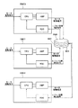
図3は、ブラシレスモータBM1〜BM3の駆動回路を示すブロック図である。外部のコンピュータからモータ回転指令が入力されたとき、ブラシレスモータBM1用のモータ制御回路DMC1、ブラシレスモータBM2用のモータ制御回路DMC2、ブラシレスモータBM3用のモータ制御回路DMC3は、それぞれ、そのCPUから3層アンプ(AMP)に駆動信号を出力し、3層アンプ(AMP)からブラシレスモータBM1〜BM3に駆動電流が供給される。それによりブラシレスモータBM1〜BM3の円筒状部材23,23’、23”が独立して回転し、後述するようにしてアームアセンブリを移動させるようになっている。円筒状部材23,23’、23”が回転すると、上述のようにして回転角度を検出したレゾルバステータ35,36,35’、36’、35”、36”からレゾルバ信号が出力されるので、それをレゾルバデジタル変換器(RDC)でデジタル変換した後に入力したCPUは、円筒状部材23,23’、23”が指令位置に到達したか否かを判断し、指令位置に到達すれば、3層アンプ(AMP)への駆動信号を停止することで円筒状部材23,23’、23”の回転を停止させる。これにより円筒状部材23,23’、23”のサーボ制御が可能となる。
FIG. 3 is a block diagram showing a drive circuit for the brushless motors BM1 to BM3. When a motor rotation command is input from an external computer, the motor control circuit DMC1 for the brushless motor BM1, the motor control circuit DMC2 for the brushless motor BM2, and the motor control circuit DMC3 for the brushless motor BM3 are each 3 from the CPU. A drive signal is output to the layer amplifier (AMP), and a drive current is supplied from the three-layer amplifier (AMP) to the brushless motors BM1 to BM3. Thereby, the
次に、本実施の形態の3軸同軸ダイレクトドライブモータを用いたスカラーロボットについて説明する。図4は、図1の3軸同軸ダイレクトドライブモータを用いたスカラーロボットの上方から見た斜視図であり、図5は下方から見た斜視図であり、図6は、ウェハ支持部を削除した状態で示すスカラーロボットの斜視図であり、図7は、ウェハ支持部を削除した状態で示すスカラーロボットの正面図であり、図8は、ウェハ支持部を削除した状態で示すスカラーロボットの断面図である。 Next, a scalar robot using the triaxial coaxial direct drive motor of the present embodiment will be described. 4 is a perspective view of a scalar robot using the triaxial coaxial direct drive motor of FIG. 1 as viewed from above, FIG. 5 is a perspective view as viewed from below, and FIG. 6 is a wafer support portion omitted. FIG. 7 is a front view of the scalar robot shown with the wafer support removed, and FIG. 8 is a cross-sectional view of the scalar robot shown with the wafer support removed. It is.
図において、第1のブラシレスモータBM1のモータ回転子に連結された円筒状部材23の周囲には、第1アームアセンブリAA1が設けられている。第1アームアセンブリAA1において、円筒状部材23に一端側をボルト止めされた筐体状の第1フレームFR1は、その他端側に第11ポストPS11を取り付けている。第11ポストPS11の上端には、第12プーリ(第1固定環)PL12が同軸に固定されている。
In the figure, a first arm assembly AA1 is provided around a
第11ポストPS11の周囲において、第1中空シャフトHS1が玉軸受BRにより回転自在に支持されている。第1中空シャフトHS1の下端には、第11プーリ(第1回転環)PL11が連結されており、第1中空シャフトHS1の上端には、筐体状の第1アーム部AM1の一端が固定されている。第1アーム部AM1の一端側は、第12プーリPL12を収容しており、その他端には、第12ポストPS12の下端側が玉軸受BRにより回転自在に支持されている。第12ポストPS12の上端には、第13プーリ(第1末端環)PL13が固定されている。第13プーリPL13の上面には、ウェハ等を保持するための第1爪部材NL1が一体的に回転するように取り付けられている。 Around the eleventh post PS11, the first hollow shaft HS1 is rotatably supported by the ball bearing BR. An eleventh pulley (first rotating ring) PL11 is connected to the lower end of the first hollow shaft HS1, and one end of the housing-like first arm portion AM1 is fixed to the upper end of the first hollow shaft HS1. ing. One end side of the first arm portion AM1 accommodates the twelfth pulley PL12, and the lower end side of the twelfth post PS12 is rotatably supported by the ball bearing BR at the other end. A thirteenth pulley (first end ring) PL13 is fixed to the upper end of the twelfth post PS12. A first claw member NL1 for holding a wafer or the like is attached to the upper surface of the thirteenth pulley PL13 so as to rotate integrally.
第11プーリPL11の外径部と、円筒状部材23’の第1レース面23a’との間には、第11ベルトBL11が張設され、両者は外径に応じた所定の関係で回転するようになっている。又、第12プーリPL12の外径部と、第13プーリPL13の外径部との間には、第12ベルトBL12が張設され、両者は外径に応じた所定の関係で回転するようになっている。
An eleventh belt BL11 is stretched between the outer diameter portion of the eleventh pulley PL11 and the
一方、第3のブラシレスモータBM2のモータ回転子に連結された円筒状部材23”の周囲には、第2アームアセンブリAA2が設けられている。第1アームアセンブリAA1と類似の構成を有する第2アームアセンブリAA2において、円筒状部材23”に一端側をボルト止めされた筐体状の第2フレームFR2は、その他端側に第21ポストPS21が取り付けられている。第21ポストPS21の上端には、第22プーリ(第1回転環)PL22が同軸に固定されている。
On the other hand, a second arm assembly AA2 is provided around a
第21ポストPS21の周囲において、第2中空シャフトHS2が玉軸受BRにより回転自在に支持されている。第2中空シャフトHS2の下端には、第21プーリ(第2回転環)PL21が連結されており、第2中空シャフトHS2の上端には、筐体状の第2アーム部AM2の一端が固定されている。第2アーム部AM2の一端側は、第22プーリPL22を収容しており、その他端には、第22ポストPS22の下端側が玉軸受BRにより回転自在に支持されている。第22ポストPS22の上端には、第23プーリ(第2末端環)PL23が固定されている。第23プーリPL23の上面には、ウェハ等を保持するための第2爪部材NL2が一体的に回転するように取り付けられている。尚、図8に示すように、高さ方向において、第1アーム部AM1は、第2アーム部AM3とダイレクトドライブモータDとの間に進入できる寸法となっている。 Around the 21st post PS21, the second hollow shaft HS2 is rotatably supported by the ball bearing BR. A 21st pulley (second rotating ring) PL21 is connected to the lower end of the second hollow shaft HS2, and one end of the housing-like second arm portion AM2 is fixed to the upper end of the second hollow shaft HS2. ing. The one end side of the second arm portion AM2 accommodates the twenty-second pulley PL22, and the lower end side of the twenty-second post PS22 is rotatably supported by the ball bearing BR at the other end. A 23rd pulley (second end ring) PL23 is fixed to the upper end of the 22nd post PS22. A second claw member NL2 for holding a wafer or the like is attached to the upper surface of the 23rd pulley PL23 so as to rotate integrally. As shown in FIG. 8, in the height direction, the first arm portion AM1 has a dimension that allows entry between the second arm portion AM3 and the direct drive motor D.
第21プーリPL21の外径部と、円筒状部材23’の第2レース面23b’との間には、第21ベルトBL21が張設され、両者は外径に応じた所定の関係で回転するようになっている。又、第22プーリPL22の外径部と、第23プーリPL23の外径部との間には、第22ベルトBL22が張設され、両者は外径に応じた所定の関係で回転するようになっている。
The 21st belt BL21 is stretched between the outer diameter portion of the 21st pulley PL21 and the
次に、図9を用いて、スカラーロボットの動作について説明する。図9は、簡略化した第1アームアセンブリAA1を、モータの軸線方向に見た図であるが、理解しやすいように第1アーム部は省略しており、プーリ径は実際と異なる。まず、第2のブラシレスモータBM2を静止させ、第1のブラシレスモータBM1を動作させることより、第1フレームが反時計回りに回動したとすると、第1フレームFR1の旋回により、第1ポストPS1が図9に示すようにモータの回転軸線Oの回りを移動する。 Next, the operation of the scalar robot will be described with reference to FIG. FIG. 9 is a view of the simplified first arm assembly AA1 as viewed in the axial direction of the motor, but the first arm portion is omitted for easy understanding, and the pulley diameter is different from the actual one. First, assuming that the first brushless motor BM2 is stationary and the first brushless motor BM1 is operated to rotate the first frame counterclockwise, the first post PS1 is rotated by the rotation of the first frame FR1. 9 moves around the rotation axis O of the motor as shown in FIG.
ところが、第2のブラシレスモータBM2が静止しているので、第2円筒状部材23’と第11ベルトBL11により連結された第11プーリPL11は回転が拘束される。よって、第11ポストPS11と第1中空シャフトHS1との間に相対回転が生じ、それにより第1フレームFR1に対して第1アーム部AM1が角度付けされることとなる。 However, since the second brushless motor BM2 is stationary, the rotation of the eleventh pulley PL11 connected by the second cylindrical member 23 'and the eleventh belt BL11 is restricted. Therefore, relative rotation occurs between the eleventh post PS11 and the first hollow shaft HS1, and thereby the first arm portion AM1 is angled with respect to the first frame FR1.
このとき、第1アーム部AM1に取り付けられた第12ポストPS12も変位するが、第12ポストPS12は、玉軸受BRにより回転自在に支持されており、且つ第13プーリPL13及び第12ベルトBL12を介して第11ポストPS11との間で回転が拘束されているため、結局、第13プーリPL13に取り付けられた第1爪部材NL1が、元の位置に対して、モータの回転軸線Oに対して半径方向に直線的に移動することとなる。即ち、第2のブラシレスモータBM2を静止させ、第1のブラシレスモータBM1を動作させることより、第1爪部材NL1が半径方向に所望の距離だけ移動する。逆方向も同様である。 At this time, the twelfth post PS12 attached to the first arm portion AM1 is also displaced, but the twelfth post PS12 is rotatably supported by the ball bearing BR, and the thirteenth pulley PL13 and the twelfth belt BL12 are connected. As a result, the rotation of the first claw member NL1 attached to the thirteenth pulley PL13 with respect to the original position relative to the rotation axis O of the motor is restricted. It will move linearly in the radial direction. That is, the first claw member NL1 is moved by a desired distance in the radial direction by stopping the second brushless motor BM2 and operating the first brushless motor BM1. The same applies to the reverse direction.
一方、第2のブラシレスモータBM2を静止させ、第3のブラシレスモータBM3を動作させることより、同様に、第2爪部材NL2が半径方向に所望の距離だけ移動する。逆方向も同様である。 On the other hand, since the second brushless motor BM2 is stopped and the third brushless motor BM3 is operated, the second claw member NL2 is similarly moved by a desired distance in the radial direction. The same applies to the reverse direction.
更に、ブラシレスモータBM1〜BM3を、同時に同一方向へ同速度・同角度で作動させることにより、アームアセンブリAA1,AA2を旋回前の姿勢を保ちながら、任意の角度で旋回させることができる。以上の組み合わせにより、爪部材NL1、NL2を独立して任意の2次元座標の位置に変位させることができる。 Furthermore, by simultaneously operating the brushless motors BM1 to BM3 in the same direction at the same speed and the same angle, the arm assemblies AA1 and AA2 can be turned at any angle while maintaining the posture before turning. With the above combination, the claw members NL1 and NL2 can be independently displaced to the positions of arbitrary two-dimensional coordinates.
本実施の形態によれば、モータ回転子を支持する軸受装置の静止輪を隔壁に取り付ける必要が無く、機械的な剛性を高めることができる。また、隔壁13とベース10との間に設けたO−リングORを分解しないで軸受交換を行える構造とすることができる。更に、ダイレクト駆動のため、多重シャフト構造は不要となり、各軸の慣性とねじり剛性がほぼ同じに設定できるので、バランスよい駆動性能が実現できる。多重シャフトと磁気カップリングによる動力伝達構造の代わりにダイレクト駆動と磁気カップリングによる位置信号伝達の構造を使用することによって、ダイレクト検出が実現でき、ロボット位置決め精度が向上できる。特に、3つのモータで二つのアーム部を独立に駆動でき、搬送効率向上ができる。
According to the present embodiment, it is not necessary to attach the stationary ring of the bearing device that supports the motor rotor to the partition wall, and the mechanical rigidity can be increased. Further, the bearing can be replaced without disassembling the O-ring OR provided between the
以上、本実施例においては、アウタロータ方式のモータを例として説明したが、インナロータ方式でも同様の効果が得られる。その場合、永久磁石とヨーク(磁石ホルダ)の端面の接線交点は、本実施の形態の如くヨークとの隙間以上は浮くことができない角度にすべきである。また、永久磁石の飛散防止のために、モータ回転子に非磁性の薄管を被せると良い。永久磁石は、ネオジウム(Nd−Fe−B)系磁石を用い、耐食性を高めるためのコーティングとして、ニッケルコーティングを施した例を用いて説明したが、この材質、表面処理に限定されるものではなく、使用される環境などによって適宜変更されるものであり、例えばベークアウト時の温度条件によっては高温減磁しにくいサマリウム−コバルト(Sm−Co)系の磁石を用いるべきであり、超真空中で使用されるのであればアウトガス遮断性の高い窒化チタンコーティングを施すべきである。 As described above, in the present embodiment, the outer rotor type motor has been described as an example, but the same effect can be obtained by the inner rotor type. In that case, the tangent intersection of the end face of the permanent magnet and the yoke (magnet holder) should be at an angle that cannot float more than the gap with the yoke as in this embodiment. In order to prevent the permanent magnets from scattering, it is preferable to cover the motor rotor with a nonmagnetic thin tube. The permanent magnet has been described using a neodymium (Nd-Fe-B) -based magnet as an example of nickel coating as a coating for enhancing corrosion resistance, but is not limited to this material and surface treatment. The samarium-cobalt (Sm-Co) magnet, which is difficult to demagnetize at high temperature, should be used depending on the temperature conditions at the time of baking out. If used, a titanium nitride coating with a high outgas barrier should be applied.
また、ヨークは、低炭素鋼を材料とし、ニッケルめっきを施した例を用いて説明したが、この材質、表面処理に限定されるものではなく、使用される環境などによって適宜変更されるものであり、特に表面処理に関しては、超真空中で使朋されるのであればピンホールの少ないカニゼンめっきやクリーンエスめっき、窒化チタンコーティング等を施すべきである。 In addition, the yoke has been described using an example in which nickel is plated with low carbon steel as a material. However, the yoke is not limited to this material and surface treatment, and may be appropriately changed depending on the environment used. In particular, regarding surface treatment, if used in ultra-vacuum, Kanigen plating, clean s plating, titanium nitride coating, etc. with few pinholes should be applied.
また、真空軸受装置は、真空用グリス潤滑の背面組合わせアンギュラ玉軸受を用いた例を説明したが、この形式、材質、潤滑方法に限定されるものではなく、使用される環境、荷重条件、回転速度などによって適宜変更されるものであり、クロスローラ軸受であっても良いし、深溝玉軸受や4点接触軸受として予圧をかける構造としても良いし、超真空中で使用される場合は、軌道輪に金や銀などの軟質金属をプレーティングしたような、ガス放出のない金属潤滑としたものを用いても良い。 In addition, the vacuum bearing device has been described as an example using a vacuum grease lubricated back-combination angular contact ball bearing, but is not limited to this type, material, and lubrication method, and the environment used, load conditions, It is appropriately changed depending on the rotational speed, and may be a cross roller bearing, a deep groove ball bearing or a structure that applies preload as a four-point contact bearing, and when used in ultra-vacuum, A metal lubrication that does not release gas, such as plating of a soft metal such as gold or silver, may be used.
また、ホルダやボルトの材質は、製造コストや使用される環境などによって適宣変更されるものである。更に、モータ回転子は、必ずしも一体の円形である必要もなく、同じ機能ができれば、分割構成となってもかまわない。この場合、素材コストを低減できる。 Further, the material of the holder and the bolt is appropriately changed depending on the manufacturing cost and the environment in which it is used. Further, the motor rotor does not necessarily have to be an integral circle, and may have a divided configuration as long as the same function can be achieved. In this case, the material cost can be reduced.
また、磁気カップリングとして機能する内側ロータとして、永久磁石とバックヨークを用いた形式で説明したが、永久磁石とバックヨークの材質および形状はこれに限定されるものではない。例えば、レゾルバの質量と軸受の摩擦トルクによっては、ロータと同極数でなくても良いし、同幅でなくても良い。永久磁石を用いない突極でも良い。 In addition, the inner rotor functioning as a magnetic coupling has been described as using a permanent magnet and a back yoke. However, the material and shape of the permanent magnet and the back yoke are not limited thereto. For example, depending on the mass of the resolver and the friction torque of the bearing, the number of poles may not be the same as that of the rotor, and the width may not be the same. A salient pole that does not use a permanent magnet may be used.
また、角度検出器としてレゾルバを用いた例で説明したが、製造コストや分解能によって適宜変更されるものであり、例えば光学式のロータリエンコーダでも良い。 Further, although an example in which a resolver is used as an angle detector has been described, it can be appropriately changed depending on manufacturing cost and resolution, and for example, an optical rotary encoder may be used.
また、角度検出器の回転側を回転自在に支持する軸受33,33”として、グリス潤滑の深溝玉軸受を用いた例を説明したが、この形式、潤滑方法に限定されるものではなく、設置スぺースや摩擦トルク、回転速度などによって適宜変更されるものであり、高速回転や摩擦トルクの低減など、多点接触軸受を用いることができない場合は、アンギュラ軸受や深溝玉軸受を各軸ごとに2個配置して、予圧をかける構造としても良い。
In addition, as an example of using a grease-lubricated deep groove ball bearing as the
また、その他の隔壁の外、中に配置される構造部品および隔壁の材質、形状、製造方法は、製造コストや使用される環境、荷重条件、構成などによって適宜変更されるものである。 In addition to the other partition walls, the structural parts and the material, shape, and manufacturing method of the partition parts and the partition walls are appropriately changed depending on the manufacturing cost, the environment used, the load conditions, the configuration, and the like.
以上、本発明を実施の形態を参照して説明してきたが、本発明は上記実施の形態に限定して解釈されるべきではなく、適宜変更・改良が可能であることはもちろんである。例えば、本実施の形態のスカラーロボットは、真空雰囲気に限らず、大気外の雰囲気で使用することができる。例えば、半導体製造工程の場合、真空排気後に真空槽内部にエッチング用の反応性ガスが導入されることがあるが、本実施の形態のダイレクトドライブモータでは、隔壁により内部と外部とが遮蔽されているため、モータコイルや絶縁材等がエッチングされてしまうおそれもない。 The present invention has been described above with reference to the embodiments. However, the present invention should not be construed as being limited to the above-described embodiments, and can be modified or improved as appropriate. For example, the scalar robot according to the present embodiment is not limited to a vacuum atmosphere, and can be used in an atmosphere outside the atmosphere. For example, in the case of a semiconductor manufacturing process, a reactive gas for etching may be introduced into the vacuum chamber after evacuation, but in the direct drive motor of the present embodiment, the inside and the outside are shielded by the partition wall. Therefore, there is no possibility that the motor coil, the insulating material, and the like are etched.
10 ベース
10a 円盤部
10b 円筒部
10c 周溝
10d 遮蔽板
12A 第1本体
12B 第2本体
12C 第3本体
12D 円板
12a フランジ部
12b フランジ部
12c フランジ部
13 隔壁
13a 底部
13b 円筒部
13c 取付部
19、19’、19” アンギュラ玉軸受
21、21’、21” 外側ロータ部材
21a、21a、21a” 磁石ホルダ
21b、21b’、21b” 永久磁石
21c、21c’、21c” 真空側カップリング磁石
21d、21d’、21d” ヨーク
21e、21e’、21e” 止め輪
21f、21f’、21f” 止め輪用溝
23、23’、23” 円筒状部材
23a’ 第1レース面
23b’ 第2レース面
29、29’、29” ステータ
30、30’、30” 内側ロータ
30a、30a’、30a” 永久磁石
30b、30b’、30B” バックヨーク
31、31’,31” ロータホルダ
33、33’、33” 玉軸受
34a、34a’、34a” インクリメンタルレゾルバロータ
34b、34b’、34b” アブソリュートレゾルバロータ
34c、34c’、34c” 回転筒
35、35’,35” インクリメンタルレゾルバステータ
36、36’、36” アブソリュートレゾルバステータ
AA1 第1アームアセンブリ
AA2 第2アームアセンブリ
AM1 第1アーム部
AM2 第2アーム部
B ボルト
BL11 第11ベルト
BL12 第12ベルト
BL21 第21ベルト
BL22 第22ベルト
BM1〜BM3 ブラシレスモータ
BR 玉軸受
CN1 コネクタ
CN2 コネクタ
D ダイレクトドライブモータ
DMC1 モータ制御回路
DMC2 モータ制御回路
DMC3 モータ制御回路
FR1 第1フレーム
FR2 第2フレーム
HS1 第1中空シャフト
HS2 第2中空シャフト
LB 長ボルト
NL1 第1爪部材
NL2 第2爪部材
OR O−リング
PL11 第11プーリ
PL12 第12プーリ
PL13 第13プーリ
PL21 第21プーリ
PL22 第22プーリ
PL23 第23プーリ
PS11 第11ポスト
PS12 第12ポスト
PS21 第21ポスト
PS22 第22ポスト
PT1 抑え板
PT2 抑え板
PT3 抑え部材
PT4 抑え部材
PT5 抑え部材
DESCRIPTION OF SYMBOLS 10 Base 10a Disk part 10b Cylindrical part 10c Circumferential groove 10d Shielding board 12A 1st main body 12B 2nd main body 12C 3rd main body 12D Disc 12a Flange part 12b Flange part 12c Flange part 13 Partition 13a Bottom part 13b Cylindrical part 13c Attachment part 19, 19 ', 19 "angular contact ball bearings 21, 21', 21" outer rotor members 21a, 21a, 21a "magnet holders 21b, 21b ', 21b" permanent magnets 21c, 21c', 21c "vacuum side coupling magnets 21d, 21d ', 21d "Yoke 21e, 21e', 21e" Retaining ring 21f, 21f ', 21f "Retaining ring groove 23, 23', 23" Cylindrical member 23a 'First race surface 23b' Second race surface 29, 29 ', 29 "Stator 30, 30', 30" Inner rotor 30a, 30a ', 30a "Permanent magnet 30b, 30b ', 30B "Back yoke 31, 31', 31" Rotor holder 33, 33 ', 33 "Ball bearing 34a, 34a', 34a" Incremental resolver rotor 34b, 34b ', 34b "Absolute resolver rotor 34c, 34c' 34c "rotating cylinder 35, 35 ', 35" incremental resolver stator 36, 36', 36 "absolute resolver stator AA1 first arm assembly AA2 second arm assembly AM1 first arm part AM2 second arm part B bolt BL11 eleventh Belt BL12 12th belt BL21 21st belt BL22 22nd belt BM1 to BM3 Brushless motor BR Ball bearing CN1 Connector CN2 Connector D Direct drive motor DMC1 Motor control circuit DMC2 Motor control circuit MC3 Motor control circuit FR1 1st frame FR2 2nd frame HS1 1st hollow shaft HS2 2nd hollow shaft LB Long bolt NL1 1st claw member NL2 2nd claw member OR O-ring PL11 11th pulley PL12 12th pulley PL13 13th Pulley PL21 21st pulley PL22 22nd pulley PL23 23rd pulley PS11 11th post PS12 12th post PS21 21st post PS22 22nd post PT1 restraining plate PT2 restraining plate PT3 restraining member PT4 restraining member PT5 restraining member
Claims (9)
各モータは、表面磁石型の周対向ブラシレスモータであって、
べースと、
前記ベースから延在し、大気側と大気外側を隔絶する隔壁と、
前記隔壁に対して大気外側に配置されたモータ回転子と、
前記モータ回転子を回転自在に支持する真空軸受装置と、
前記モータ回転子に対向し、前記隔壁に対して大気側に配置されたステータと、
前記隔壁に対して大気側に配置され、前記モータ回転子と共につれ回る大気側回転子と
前記大気側回転子の回転角度を検出する角度検出器と
前記大気側回転子を回転自在に支持する大気軸受装置と、を有しており、
前記大気側回転子は、前記ベースに対して、前記大気軸受装置により支持されており
前記ステータと、前記大気軸受装置と、前記大気側回転子と、前記角度検出器と、前記モータ回転子と、前記真空軸受装置のうち少なくとも2つは、モータ軸線方向において互いに少なくとも一部が重合する位置に配置されていることを特徴するダイレクトドライブモータ。 In a 3-axis coaxial direct drive motor that is used in an atmosphere outside the atmosphere and has three motors arranged in series,
Each motor is a surface magnet type circumferentially opposed brushless motor,
Base,
A partition wall extending from the base and isolating the atmosphere side and the atmosphere outside;
A motor rotor disposed outside the atmosphere with respect to the partition;
A vacuum bearing device for rotatably supporting the motor rotor;
A stator facing the motor rotor and disposed on the atmosphere side with respect to the partition;
An atmosphere-side rotor that is arranged on the atmosphere side with respect to the partition wall and rotates together with the motor rotor, an angle detector that detects a rotation angle of the atmosphere-side rotor, and an atmosphere that rotatably supports the atmosphere-side rotor. A bearing device,
The atmosphere side rotor is supported by the atmosphere bearing device with respect to the base. The stator, the atmosphere bearing device, the atmosphere side rotor, the angle detector, and the motor rotor The direct drive motor is characterized in that at least two of the vacuum bearing devices are arranged at positions where at least a part of the vacuum bearing devices overlap in the motor axial direction.
前記第1のモータに隣接する第2のモータの前記真空軸受装置の一方の輪は、前記第1のモータの前記モータ回転子に固定されており、他方の輪は、前記第2のモータの前記モータ回転子に固定されており、
前記第2のモータに隣接する第3のモータの前記真空軸受装置の一方の輪は、前記第2のモータの前記モータ回転子に固定されており、他方の輪は、前記第3のモータの前記モータ回転子に固定されていることを特徴する請求項1又は2に記載のダイレクトドライブモータ。 Of the three-axis coaxial direct drive motor, the stationary wheel of the vacuum bearing device of the first motor is fixed to a stationary member other than the partition wall, and the rotating wheel is connected to the motor rotor of the first motor. Fixed,
One wheel of the vacuum bearing device of the second motor adjacent to the first motor is fixed to the motor rotor of the first motor, and the other wheel is fixed to the second motor. Fixed to the motor rotor,
One ring of the vacuum bearing device of the third motor adjacent to the second motor is fixed to the motor rotor of the second motor, and the other ring of the third motor The direct drive motor according to claim 1, wherein the direct drive motor is fixed to the motor rotor.
Priority Applications (1)
| Application Number | Priority Date | Filing Date | Title |
|---|---|---|---|
| JP2008153022A JP5288164B2 (en) | 2008-06-11 | 2008-06-11 | Scalar robot |
Applications Claiming Priority (1)
| Application Number | Priority Date | Filing Date | Title |
|---|---|---|---|
| JP2008153022A JP5288164B2 (en) | 2008-06-11 | 2008-06-11 | Scalar robot |
Publications (2)
| Publication Number | Publication Date |
|---|---|
| JP2009303331A true JP2009303331A (en) | 2009-12-24 |
| JP5288164B2 JP5288164B2 (en) | 2013-09-11 |
Family
ID=41549636
Family Applications (1)
| Application Number | Title | Priority Date | Filing Date |
|---|---|---|---|
| JP2008153022A Expired - Fee Related JP5288164B2 (en) | 2008-06-11 | 2008-06-11 | Scalar robot |
Country Status (1)
| Country | Link |
|---|---|
| JP (1) | JP5288164B2 (en) |
Cited By (4)
| Publication number | Priority date | Publication date | Assignee | Title |
|---|---|---|---|---|
| US8716909B2 (en) | 2011-09-16 | 2014-05-06 | Persimmon Technologies, Corp. | Robot with heat dissipating stator |
| JP2014520681A (en) * | 2011-07-13 | 2014-08-25 | ブルックス オートメーション インコーポレイテッド | Compact direct drive spindle |
| JP2016116297A (en) * | 2014-12-12 | 2016-06-23 | 日本精工株式会社 | Motor, transfer device, machine tool, flat panel display manufacturing apparatus, and semiconductor manufacturing apparatus |
| US10476354B2 (en) | 2011-09-16 | 2019-11-12 | Persimmon Technologies Corp. | Robot drive with isolated optical encoder |
Citations (2)
| Publication number | Priority date | Publication date | Assignee | Title |
|---|---|---|---|---|
| JPH11215780A (en) * | 1998-01-30 | 1999-08-06 | Tamagawa Seiki Co Ltd | Vacuum motor |
| JP2006109657A (en) * | 2004-10-07 | 2006-04-20 | Nsk Ltd | Motor system |
-
2008
- 2008-06-11 JP JP2008153022A patent/JP5288164B2/en not_active Expired - Fee Related
Patent Citations (2)
| Publication number | Priority date | Publication date | Assignee | Title |
|---|---|---|---|---|
| JPH11215780A (en) * | 1998-01-30 | 1999-08-06 | Tamagawa Seiki Co Ltd | Vacuum motor |
| JP2006109657A (en) * | 2004-10-07 | 2006-04-20 | Nsk Ltd | Motor system |
Cited By (13)
| Publication number | Priority date | Publication date | Assignee | Title |
|---|---|---|---|---|
| US10493620B2 (en) | 2011-07-13 | 2019-12-03 | Brooks Automation, Inc. | Compact direct drive spindle |
| JP2014520681A (en) * | 2011-07-13 | 2014-08-25 | ブルックス オートメーション インコーポレイテッド | Compact direct drive spindle |
| US11772261B2 (en) | 2011-07-13 | 2023-10-03 | Brooks Automation Us, Llc | Compact direct drive spindle |
| US11110598B2 (en) | 2011-07-13 | 2021-09-07 | Brooks Automation, Inc. | Compact direct drive spindle |
| US9751209B2 (en) | 2011-07-13 | 2017-09-05 | Brooks Automation, Inc. | Compact direct drive spindle |
| US11031850B2 (en) | 2011-09-16 | 2021-06-08 | Persimmon Technologies Corporation | Robot drive with isolated optical encoder |
| US10020704B2 (en) | 2011-09-16 | 2018-07-10 | Persimmon Technologies Corporation | Electrical connection through motor housing |
| US10476354B2 (en) | 2011-09-16 | 2019-11-12 | Persimmon Technologies Corp. | Robot drive with isolated optical encoder |
| US9800114B2 (en) | 2011-09-16 | 2017-10-24 | Persimmon Technologies Corporation | Robot drive with radially adjustable sensor connection |
| US8716909B2 (en) | 2011-09-16 | 2014-05-06 | Persimmon Technologies, Corp. | Robot with heat dissipating stator |
| US11469649B2 (en) | 2011-09-16 | 2022-10-11 | Persimmon Technologies Corporation | Robot drive with isolated optical encoder |
| JP2014528170A (en) * | 2011-09-16 | 2014-10-23 | パーシモン テクノロジーズ コーポレイションPersimmon Technologies, Corp. | Driving a robot with a passive rotor |
| JP2016116297A (en) * | 2014-12-12 | 2016-06-23 | 日本精工株式会社 | Motor, transfer device, machine tool, flat panel display manufacturing apparatus, and semiconductor manufacturing apparatus |
Also Published As
| Publication number | Publication date |
|---|---|
| JP5288164B2 (en) | 2013-09-11 |
Similar Documents
| Publication | Publication Date | Title |
|---|---|---|
| JP5288164B2 (en) | Scalar robot | |
| JP4930050B2 (en) | Direct drive motor | |
| JP4692050B2 (en) | Rotating support device | |
| JP2010273539A (en) | Direct drive motor | |
| JP4581757B2 (en) | Motor system | |
| JP4792793B2 (en) | Direct drive motor | |
| JP4656380B2 (en) | Motor system | |
| JP5401837B2 (en) | Direct drive motor, transfer robot, and semiconductor manufacturing equipment | |
| JP4711218B2 (en) | Motor system | |
| JP2009038910A (en) | Brushless motor | |
| JP4618422B2 (en) | Direct drive motor | |
| JP2006109655A (en) | Direct drive motor | |
| JP2009038911A (en) | Brushless motor | |
| JP2006296057A (en) | Motor | |
| JP4613574B2 (en) | Motor system | |
| JP2012249519A (en) | Direct drive motor, transport device, and semiconductor manufacturing apparatus | |
| JP4736025B2 (en) | Direct drive motor | |
| JP4613573B2 (en) | Motor system | |
| JP2008167588A (en) | Brushless motor | |
| JP4692156B2 (en) | Motor system | |
| JP2009131104A (en) | Transfer robot | |
| JP2006296061A (en) | Motor | |
| WO2008050418A1 (en) | Rotation support device | |
| JP5246278B2 (en) | Direct drive motor | |
| JP2021118675A (en) | motor |
Legal Events
| Date | Code | Title | Description |
|---|---|---|---|
| A621 | Written request for application examination |
Free format text: JAPANESE INTERMEDIATE CODE: A621 Effective date: 20110609 |
|
| A977 | Report on retrieval |
Free format text: JAPANESE INTERMEDIATE CODE: A971007 Effective date: 20130220 |
|
| A131 | Notification of reasons for refusal |
Free format text: JAPANESE INTERMEDIATE CODE: A131 Effective date: 20130221 |
|
| A521 | Request for written amendment filed |
Free format text: JAPANESE INTERMEDIATE CODE: A523 Effective date: 20130416 |
|
| TRDD | Decision of grant or rejection written | ||
| A01 | Written decision to grant a patent or to grant a registration (utility model) |
Free format text: JAPANESE INTERMEDIATE CODE: A01 Effective date: 20130509 |
|
| A61 | First payment of annual fees (during grant procedure) |
Free format text: JAPANESE INTERMEDIATE CODE: A61 Effective date: 20130522 |
|
| R150 | Certificate of patent or registration of utility model |
Ref document number: 5288164 Country of ref document: JP Free format text: JAPANESE INTERMEDIATE CODE: R150 |
|
| LAPS | Cancellation because of no payment of annual fees |