JP2009299806A - Seal structure and power transmitting device - Google Patents
Seal structure and power transmitting device Download PDFInfo
- Publication number
- JP2009299806A JP2009299806A JP2008155558A JP2008155558A JP2009299806A JP 2009299806 A JP2009299806 A JP 2009299806A JP 2008155558 A JP2008155558 A JP 2008155558A JP 2008155558 A JP2008155558 A JP 2008155558A JP 2009299806 A JP2009299806 A JP 2009299806A
- Authority
- JP
- Japan
- Prior art keywords
- dust cover
- seal
- cover
- cover member
- end portion
- Prior art date
- Legal status (The legal status is an assumption and is not a legal conclusion. Google has not performed a legal analysis and makes no representation as to the accuracy of the status listed.)
- Withdrawn
Links
Images

Classifications
-
- F—MECHANICAL ENGINEERING; LIGHTING; HEATING; WEAPONS; BLASTING
- F16—ENGINEERING ELEMENTS AND UNITS; GENERAL MEASURES FOR PRODUCING AND MAINTAINING EFFECTIVE FUNCTIONING OF MACHINES OR INSTALLATIONS; THERMAL INSULATION IN GENERAL
- F16H—GEARING
- F16H48/00—Differential gearings
- F16H48/06—Differential gearings with gears having orbital motion
- F16H48/08—Differential gearings with gears having orbital motion comprising bevel gears
Landscapes
- Sealing With Elastic Sealing Lips (AREA)
- General Details Of Gearings (AREA)
Abstract
Description
本発明は、シール構造および動力伝達装置に関し、特に、軸線回りに相対回転可能に設けられた第一部材と第二部材との間の隙間を密封するシール構造と、そのシール構造を備える動力伝達装置に関する。 The present invention relates to a seal structure and a power transmission device, and in particular, a seal structure that seals a gap between a first member and a second member that are provided to be relatively rotatable about an axis, and a power transmission that includes the seal structure. Relates to the device.
従来のシール構造に関する技術は、たとえば実開平6−10025号公報(特許文献1)、特開平9−174346号公報(特許文献2)および実開平5−87359号公報(特許文献3)などに開示されている。特許文献1では、シャフト部の摺動に対してもシール性を保持するよう、ラジアル方向(径方向)に延びるリップが相手材のラジアル面に当接されている構成が提案されている。
軸線回りに相対回転可能に設けられた第一部材と第二部材との間の隙間を密封するシール構造の場合、リップ部を含むシール材とカバー部材とを備え、軸線方向と直交する径方向に延設されるカバー部材などの相手材のスラスト面にリップ部を当接させる構成が、シール性能上有利である。 In the case of a seal structure that seals the gap between the first member and the second member that are provided so as to be relatively rotatable around the axis, the seal member including the lip portion and the cover member are provided, and the radial direction is orthogonal to the axial direction. A configuration in which the lip portion is brought into contact with a thrust surface of a mating member such as a cover member that is extended to the side is advantageous in terms of sealing performance.
相対回転する第一部材または第二部材のラジアル面にリップ部が当接されていると、回転中に回転軸周りに偏心する軸ずれが発生した場合に、シール性能が低下するおそれがあると考えられる。これに対し、カバー部材のスラスト面にリップ部を当接させた場合、回転中に軸ずれが発生してもシール性能への影響は微小である。しかし、特許文献1〜3に記載の技術では、相手材のスラスト方向にリップ部を当接させるための工夫は開示されていない。 When the lip portion is in contact with the radial surface of the first member or the second member that rotates relative to each other, there is a risk that the sealing performance may be deteriorated when an axial deviation occurs around the rotation axis during rotation. Conceivable. On the other hand, when the lip portion is brought into contact with the thrust surface of the cover member, the influence on the sealing performance is small even if an axial deviation occurs during rotation. However, the techniques described in Patent Documents 1 to 3 do not disclose a device for bringing the lip portion into contact with the mating member in the thrust direction.
本発明は上記の問題に鑑みてなされたものであり、その主たる目的は、径方向に延設されるカバー部材のスラスト面にリップ部を当接させることを可能とする、シール構造を提供することである。 The present invention has been made in view of the above problems, and a main object thereof is to provide a seal structure that enables a lip portion to abut against a thrust surface of a cover member extending in a radial direction. That is.
本発明に係るシール構造は、軸線回りに相対回転可能に設けられた第一部材と第二部材との間の隙間を密封するシール構造である。シール構造は、シール材と、カバー部材と、山部とを備える。シール材は、第二部材に支持されている。このシール材が第一部材に密着して、第一部材と第二部材との間の隙間を密封する。第一部材は、第二部材に対向する対向面を有する。カバー部材は、第一部材の対向面から、軸線と直交する径方向に沿って第二部材に向かって延設される。山部は、第一部材が対向面から径方向に突起して形成されている。山部は、シール材から離れる側からカバー部材と当接して、軸線方向におけるカバー部材の位置決めを行なう。シール材は、軸線方向に沿って延設されたリップ部を有する。カバー部材は、シール材に対向するスラスト面を有する。リップ部は、カバー部材のスラスト面に当接している。 The seal structure according to the present invention is a seal structure that seals a gap between a first member and a second member that are provided so as to be relatively rotatable about an axis. The seal structure includes a seal material, a cover member, and a peak portion. The sealing material is supported by the second member. The sealing material is in close contact with the first member and seals the gap between the first member and the second member. The first member has a facing surface that faces the second member. The cover member extends from the facing surface of the first member toward the second member along a radial direction orthogonal to the axis. The peak portion is formed by projecting the first member in the radial direction from the facing surface. The peak portion contacts the cover member from the side away from the sealing material to position the cover member in the axial direction. The sealing material has a lip portion extending along the axial direction. The cover member has a thrust surface facing the seal material. The lip portion is in contact with the thrust surface of the cover member.
好ましくは、カバー部材は、軸線方向に沿ってシール材から離れる向きに延びる、基部を有する。基部において、カバー部材は第一部材に固定支持されている。 Preferably, the cover member has a base portion extending in the direction away from the sealing material along the axial direction. At the base, the cover member is fixedly supported by the first member.
好ましくは、山部は、カバー部材と当接する当接部を有する。第一部材には、当接部から軸線方向に沿って窪んだ窪み部が形成されている。基部は、窪み部の内部に収容されている。 Preferably, the peak portion has a contact portion that contacts the cover member. The first member is formed with a recessed portion that is recessed from the contact portion along the axial direction. The base is housed inside the recess.
好ましくは、第二部材は、軸線方向端部を有する。カバー部材は、軸線方向端部を覆うように径方向に延在している。 Preferably, the second member has an axial end portion. The cover member extends in the radial direction so as to cover the axial end portion.
好ましくは、カバー部材は、径方向において軸線方向端部に対して第一部材から離れる側にある先端部を有する。 Preferably, the cover member has a distal end portion on a side away from the first member with respect to the axial end portion in the radial direction.
好ましくは、先端部が軸線方向および径方向に対して傾斜して設けられている。カバー部材によって、軸線方向端部が囲まれている。 Preferably, the tip portion is provided to be inclined with respect to the axial direction and the radial direction. An end portion in the axial direction is surrounded by the cover member.
好ましくは、シール材は、環状部材を介在させて第二部材に支持されている。環状部材は、軸線方向端部を覆うように形成されている。環状部材は、径方向において軸線方向端部に対して第一部材から離れる側に突き出した突出部を有する。突出部は、カバー部材と対向している。 Preferably, the sealing material is supported by the second member with an annular member interposed therebetween. The annular member is formed so as to cover the end portion in the axial direction. The annular member has a protruding portion that protrudes toward the side away from the first member with respect to the axial end portion in the radial direction. The protruding portion faces the cover member.
本発明に係る動力伝達装置は、回転シャフトと、ハウジングと、シール構造とを備える。回転シャフトは、回転可能に設けられている。ハウジングは、回転シャフトを取り囲む。シール構造は、上記のいずれかの局面に係るシール構造であって、回転シャフトとハウジングとの間の隙間を密閉する。 The power transmission device according to the present invention includes a rotating shaft, a housing, and a seal structure. The rotating shaft is rotatably provided. The housing surrounds the rotating shaft. The seal structure is a seal structure according to any one of the above aspects, and seals a gap between the rotating shaft and the housing.
本発明のシール構造によると、カバー部材の軸線方向における位置決めが行なわれるため、軸線方向におけるカバー部材の設置位置についての誤差を小さく抑えることができる。したがって、軸線方向に沿って延設されたシール材のリップ部を確実にカバー部材に当接させることができるので、泥水の浸入を抑制し、シール構造の耐泥水性を向上させることができる。 According to the seal structure of the present invention, since the cover member is positioned in the axial direction, an error in the installation position of the cover member in the axial direction can be reduced. Therefore, the lip portion of the sealing material extending along the axial direction can be reliably brought into contact with the cover member, so that intrusion of muddy water can be suppressed and the muddy water resistance of the seal structure can be improved.
以下、図面に基づいてこの発明の実施の形態を説明する。なお、以下の図面において、同一または相当する部分には同一の参照番号を付し、その説明は繰返さない。 Embodiments of the present invention will be described below with reference to the drawings. In the following drawings, the same or corresponding parts are denoted by the same reference numerals, and description thereof will not be repeated.
なお、以下に説明する実施の形態において、各々の構成要素は、特に記載がある場合を除き、本発明にとって必ずしも必須のものではない。また、以下の実施の形態において、個数、量などに言及する場合、特に記載がある場合を除き、上記個数などは例示であり、本発明の範囲は必ずしもその個数、量などに限定されない。 In the embodiments described below, each component is not necessarily essential for the present invention unless otherwise specified. In the following embodiments, when referring to the number, amount, etc., unless otherwise specified, the above number is an example, and the scope of the present invention is not necessarily limited to the number, amount, etc.
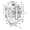
図1は、本実施の形態のシール構造を備える、車両の動力伝達装置としてのディファレンシャルギヤ装置を示す断面模式図である。図1には、車両に搭載され、エンジンなどの駆動力源から入力される回転駆動力を駆動輪に伝達する、動力伝達装置の一部を示している。本実施の形態の動力伝達装置は、エンジン横置きFF(Front engine Front drive)方式をベースとした車両に適用される。 FIG. 1 is a schematic cross-sectional view showing a differential gear device as a power transmission device for a vehicle provided with the seal structure of the present embodiment. FIG. 1 shows a part of a power transmission device that is mounted on a vehicle and transmits a rotational driving force input from a driving force source such as an engine to driving wheels. The power transmission device according to the present embodiment is applied to a vehicle based on a lateral engine FF (Front engine Front drive) system.
ディファレンシャルギヤ装置100は、駆動力源より入力される回転力の一部をドライブシャフトである車軸102を経由させて左右の前輪へ伝達する、差動装置である。ディファレンシャルギヤ装置100は、トランスアクスルケース101内に収容されている。ディファレンシャルギヤ装置100は、回転シャフトとしての車軸102と、車軸102とともに回転運動を行なうディファレンシャルケース103とを備える。
The
ディファレンシャルケース103は、仮想の回転中心線である軸線Oを車軸102と共有するように設けられている。車軸102は、軸線O回りに回転可能に設けられており、トランスアクスルケース101は固定されている。つまり、車軸102は、トランスアクスルケース101に対して軸線O回りに相対的に回転可能に設けられている。ハウジングとしてのトランスアクスルケース101は、車軸102を取り囲んでいる。
The
ディファレンシャルケース103には、リングギヤ106がボルト結合されている。駆動力源で発生し、変速機で駆動力、回転速度および回転方向が変換された動力は、リングギヤ106を経てディファレンシャルケース103に伝達される。ディファレンシャルケース103の一方端側は軸受104により、他方端側は図示しない他の軸受により、それぞれ回転可能にトランスアクスルケース101に支持されている。
A
旋回時や路面に凹凸がある場合などに車軸102に回転差を与えて車両の円滑な走行を可能とするディファレンシャルギヤは、ピニオンギヤ107とサイドギヤ108とを含んで構成されている。ピニオンギヤ107はディファレンシャルケース103に取り付けられており、このピニオンギヤ107にサイドギヤ108が噛合っている。またサイドギヤ108は、スプラインにより車軸102と結合している。
The differential gear that allows the
車両が平坦路を直進する場合には、左右の駆動輪の転がる距離が等しい。そのため左右
のサイドギヤ108は同じ回転速度で回転し、サイドギヤ108の間に挟まれたピニオンギヤ107は自転せず、ディファレンシャルケース103、ピニオンギヤ107およびサイドギヤ108は一体となって公転する。
When the vehicle goes straight on a flat road, the distance that the left and right drive wheels roll is equal. Therefore, the left and right side gears 108 rotate at the same rotational speed, the
車両がカーブを曲がる場合には、カーブ外側の駆動輪の転がる距離がカーブ内側の駆動輪よりも長いため、カーブ外側のサイドギヤ108はカーブ内側のサイドギヤ108よりも速く回転する。このとき、カーブ外側のサイドギヤ108はディファレンシャルケース103よりも速く回転しており、カーブ内側のサイドギヤ108はディファレンシャルケース103よりも遅く回転している。したがって、ディファレンシャルケース103に取り付けられ左右のサイドギヤ108の間に挟まれたピニオンギヤ107は、公転だけでなく自転もするようになる。これにより、異なる速度で回転している左右のサイドギヤ108にディファレンシャルケース103からの動力を伝えることを可能にしている。
When the vehicle turns a curve, the driving wheel outside the curve rolls longer than the driving wheel inside the curve, so the
このようなディファレンシャルギヤの働きにより、車両は駆動輪と路面との間ですべりを起こすことなく、円滑にカーブを曲がったり、凹凸路面を走行することができる。 By such a differential gear, the vehicle can smoothly turn a curve or travel on an uneven road surface without causing a slip between the driving wheel and the road surface.
車軸102とトランスアクスルケース101との間の隙間には、本実施の形態のシール構造としてのオイルシール1が設けられている。オイルシール1は、トランスアクスルケース101と車軸102との間の隙間を密封して、トランスアクスルケース101内部に封入された潤滑油が外部へ漏出することを抑制している。
In the gap between the
図2は、図1に示す領域II付近を拡大視して、オイルシールを拡大して示す模式図である。図2中の左右方向であるDR1(DR1a,DR1b)方向は、軸線Oに沿う軸線方向である。また図2中の上下方向であるDR2(DR2a,DR2b)方向は、軸線Oと直交する径方向である。図2に示すように、オイルシール1は、第二部材としてのハウジング20(トランスアクスルケース101)に支持された、シール材としてのオイルシール本体30を備える。またオイルシール1は、第一部材としての軸10(車軸102)に固定された、カバー部材としてのダストカバー40を備える。
FIG. 2 is a schematic view showing an oil seal in an enlarged manner by enlarging the vicinity of the region II shown in FIG. The DR1 (DR1a, DR1b) direction that is the left-right direction in FIG. 2 is an axial direction along the axis O. Further, the DR2 (DR2a, DR2b) direction which is the vertical direction in FIG. 2 is a radial direction orthogonal to the axis O. As shown in FIG. 2, the oil seal 1 includes an
ダストカバー40は、ハウジング20に対向する軸10の対向面11から、DR2a方向に沿ってハウジング20に向かって延設されている。ダストカバー40は、オイルシール本体30に対向するシール面42を有する。またダストカバー40は、DR1a方向に沿ってオイルシール本体30から離れる向きに延びる基部43を有する。ダストカバー40は、基部43において軸10に固定支持されている。基部43は、ダストカバー40の最内径側を形成している。
The
基部43は、ダストカバー40を確実に軸10に固定するために、DR1方向における延在長さをダストカバー40の厚みの5倍以上とするように、形成することができる。たとえば、ダストカバー40が板厚1mmとして形成される場合、基部43のDR1方向の延在長さは5mm以上とすることができる。ダストカバー40の板厚は任意に設定することができ、たとえば0.8mm以上1.2mm以下の範囲とすることができる。
The base 43 can be formed so that the extending length in the DR1 direction is 5 times or more the thickness of the
基部43は、ダストカバー40をプレス加工することにより、オイルシール本体30から離れる向きに延びるように曲げられて形成される。このように曲げ加工を受けてDR1a方向に延びる基部43を形成することによって、基部43とオイルシール本体30のダストリップ32との干渉を回避することができる。ダストカバー40がダストリップ32と干渉するとオイルシール1のシール性が低下する場合があるが、本実施の形態のようにダストカバー40を形成すれば、ダストカバー40とダストリップ32との干渉を回避して、オイルシール1のシール性を向上させることができる。
The
オイルシール本体30は、アクリル系樹脂により形成されている。アクリル系樹脂を鋳鉄製のハウジング20に直接圧入すると、圧入後に逆戻りするスプリングバックが発生し、DR1方向におけるオイルシール本体30の寸法バラツキが発生することが懸念される。そのため、オイルシール本体30は、環状部材としての金属製の支持部材35を介在させてハウジング20に支持されている。
The
オイルシール本体30は、DR1a方向に沿って延設されたリップ部31と、ダストリップ32と、シール部33とを有する。シール部33の外周にはスプリングリング34が配設されており、スプリングリング34の締付力によってシール部33の軸10に対するシール性を向上させている。このシール部33がラジアル面である軸10の対向面11と密着することにより、軸10とハウジング20との間の隙間90が密封される。そして、図2中に「オイル側」と示されたハウジング20内部に封入された潤滑油が、図2中に「空気側」と示された外部へ漏出することが抑制されている。
The oil seal
リップ部31は、DR2方向に延設されているダストカバー40の、スラスト面であるシール面42に当接している。ダストカバー40は、オイルシール本体30の相手材である、サイドリップ端面当て板材として機能している。リップ部31がダストカバー40のシール面42に当接し、またダストリップ32が軸10の対向面11に当接することにより、シール部33への泥水の浸入が抑制されており、オイルシール1の耐泥水性を向上させてシール性能を向上できる構成とされている。
The
オイルシール1はまた、軸10の対向面11からDR2a方向に突設された山部12を備える。山部12は、軸10が対向面11から径方向に突起して形成されている。山部12は、ダストカバー40に対してオイルシール本体30とDR1方向の反対側に設けられている。山部12は、ダストカバー40のシール面42と反対側の面でありDR1方向においてオイルシール本体30から離れる側の面である当接面41において、ダストカバー40と当接している。
The oil seal 1 also includes a
山部12は、ダストカバー40の当接面41と当接する当接部14を有する。当接部14はDR1b方向に突設されて当接面41と当接している。当接部14において、対向面11から最もDR2方向に突出している部分は、突端部13を形成している。DR1方向におけるダストカバー40の位置決め精度を向上させるために、山部12の当接部14は削り加工され、DR1方向における寸法精度を向上させるように仕上げられている。当接部14における、突端部13に対してDR2b方向側の位置であって、突端部13に対し対向面11により近接する位置には、ダストカバー挿入部としての窪み部15が形成されている。軸10には、山部12とダストカバー40とが当接する当接部14からDR1a方向に沿って窪んだ、窪み部15が形成されている。
The
ダストカバー40の基部43は、窪み部15の内部に配設されている。基部43は、窪み部15の内部において、軸10の対向面11と接合している。窪み部15は、ダストカバー40の基部43を受入れ可能に形成されている。窪み部15の内部に基部43を収容することによって、ダストリップ32との干渉を回避しつつ基部43を確実に軸10に固定することができる。ダストカバー40の窪み部15への圧入深さは当接部14の精度により決定されるので、上述した通り、DR1方向の寸法精度が高められるように当接部14は形成されている。
The
山部12の当接部14が当接面41側からダストカバー40と当接していることにより、DR1方向におけるダストカバー40の位置決めが行なわれている。山部12によってダストカバー40のDR1方向における位置決めがされているために、シール面42のDR1方向における寸法精度も向上している。そのため、リップ部31の先端部を、確実にダストカバー40の圧入面であるシール面42に当接させることが可能とされている。
Since the
上述した通り、ダストカバー40はプレス加工により成形されており、加工寸法の公差レンジが比較的大きい。そのため、基部43においてダストカバー40を軸10に固定するのみでは、シール面42のDR1方向の位置決め精度を向上させることは困難である。そこで、本実施の形態では、山部12を用いてダストカバー40のDR1方向の位置決めを行なっている。当接部14は軸10と一体成形され、削り加工によって精度良く仕上げることが可能であるために、当接部14が当接面41に当たることによってダストカバー40のDR1方向の位置決め精度を向上させることが可能となる。
As described above, the
つまり、ダストカバー40のプレス加工公差の影響を受けることなく、シール面42のDR1方向における位置決めをすることができる。そのため、DR1方向におけるダストカバー40の設置位置についての誤差を小さく抑えることができ、オイルシール本体30のリップ部31とダストカバー40のシール面42との当たり代のバラツキを抑制することができるので、シール面42に確実にリップ部31を当接させることが可能とされている。
That is, the
当接部14の肉厚(DR2方向における当接部14の寸法)はどのような厚みとしてもよい。但し、ダストカバー40のDR2方向に対する傾斜角度を小さくしてシール面42とリップ部31との当たり代のバラツキを低減するためには、当接部14の外径(軸線O〜突端部13間の距離)はできるだけ大きくするのが望ましい。たとえば、リップ部31がシール面42と接触する部分における、軸線Oに対するダストカバー40の全振れ量を0.4mm以内とすることができ、この条件を具備するように当接部14の外径を決定することができる。なお全振れ量とは、取り付け偏心と軸偏心との2種類の和によって表される軸の偏心を示す。
The thickness of the contact portion 14 (dimension of the
ダストカバー40はまた、先端部44を有する。先端部44は、軸10とともに軸線O回りに回転するダストカバー40の最外径側を形成している。先端部44は、DR2a方向に延びるダストカバー40において、軸10の対向面11から最も離れる位置に配設されている。ダストカバー40の外径側端部である先端部44は、DR1方向とDR2方向とのいずれに対しても傾斜する、テーパ形状加工が施されて形成されている。
The
ハウジング20は、端部21を有する。ハウジング20はDR1方向に沿って延びる部分を有しており、最もDR1a方向に延びる先端に、軸線方向端部としての端部21が形成されている。端部21は、ダストカバー40の先端部44によって囲まれている。ダストカバー40は、端部21を覆うように、DR2a方向に延在している。ダストカバー40の先端部44は、DR2方向において、端部21よりも軸10の対向面11から離れる側に位置している。
The
オイルシール本体30を支持する支持部材35は、ハウジング20の端部21を覆うように形成されている。支持部材35は、端部21に対してDR2a方向に突き出した突出部36を有する。突出部36は、DR2方向において軸10から離れる側に、端部21に対して突き出している。突出部36は、DR2方向に対して傾斜するように、DR1b方向へ曲げられている。突出部36は、ダストカバー40の先端部44と対向している。
The
先端部44が端部21に被さるようにDR2a方向に延びているために、ダストカバー40とハウジング20との間の隙間が小さくなっている。支持部材35がハウジング20の外径まで延びて先端部44と対向する突出部36を形成しているために、ハウジング20の外径部におけるダストカバー40と支持部材35との間隔はさらに小さくなっている。そのため、先端部44と突出部36との間の隙間を通過してオイルシール本体30側へ流れる泥水の流路が狭められており、泥水がオイルシール本体30に向けて流れることを抑制できる構造が形成されている。
Since the
また、突出部36がDR1b方向に曲げられ、ハウジング20の外周側の面と突出部36とは鋭角を形成するように、突出部36は設けられている。このように曲げられた突出部36は、とい機構として機能し、泥水の浸入を抑制している。つまり、ハウジング20の外周面に沿ってDR1a方向に流れる泥水は、突出部36によってせき止められるので、先端部44と突出部36との間の隙間を通過して泥水がオイルシール本体30に向けて流れることをより抑制することができる。
Further, the protruding
先端部44と突出部36との間の隙間から泥水が浸入した場合でも、シール部33よりも空気側においてリップ部31が確実にダストカバー40のシール面42と当接しているために、リップ部31を通過して泥水がさらにDR2b方向へ流れてシール部33に至ることが抑制される。軸10が回転している場合、リップ部31によってせき止められた泥水には、回転に伴って発生する遠心力によって、DR2a方向へ向かう力が作用するので、泥水の浸入を一層抑制することができる。
Even when muddy water enters from the gap between the
また、ダストカバー40の先端部44が上述の通りテーパ形状に加工されているために、遠心力の作用によってダストカバー40に沿ってDR2a方向へ流れる泥水の振り切り効果が発揮される。ダストカバー40は軸10とともに回転運動するため、先端部44が回転時に発揮する振り切り効果によって、泥水の浸入をさらに抑制することが可能となる。この振り切り効果を有効に発揮するには、ダストカバー40の最外径側を形成している先端部44をテーパ形状に加工するのが好適であり、このようにすれば、軸10の回転数が増大するに従って、より大きな振り切り効果が得られる。
Further, since the
以上説明したように、本実施の形態のオイルシール1は、軸線O回りに相対回転可能に設けられた軸10とハウジング20との間の隙間90を密封する。オイルシール1は、オイルシール本体30と、ダストカバー40と、山部12とを備える。オイルシール本体30は、ハウジング20に支持されている。このオイルシール本体30が軸10に密着して、軸10とハウジング20との間の隙間90を密封する。軸10は、ハウジング20に対向する対向面11を有する。ダストカバー40は、軸10の対向面11から、軸線Oと直交するDR2方向に沿ってハウジング20に向かって延設される。
As described above, the oil seal 1 according to the present embodiment seals the
山部12は、軸10が対向面11からDR2a方向に突起して形成されている。山部12は、オイルシール本体30から離れる側からダストカバー40と当接して、DR1方向におけるダストカバー40の位置決めを行なう。オイルシール本体30は、DR1a方向に沿って延設されたリップ部31を有する。ダストカバー40は、オイルシール本体30に対向するシール面42を有する。リップ部31は、ダストカバー40のシール面42に当接している。
The
このようにすれば、ダストカバー40のDR1方向における位置決めが行なわれるため、DR1方向におけるダストカバー40の設置位置についての誤差を小さく抑えることができる。したがって、DR1a方向に沿って延設されたリップ部31を確実にダストカバー40のシール面42に当接させることができるので、泥水の浸入を抑制し、オイルシール1の耐泥水性を向上させることができる。また、リップ部31とダストカバー40との当たり代のバラツキを抑制することができるので、オイルシール本体30がダストカバー40と接触しながら軸10が回転することにより発生する損失トルクを減少させることができる。
In this way, since the
これまでの説明においては、軸10が対向面11から径方向に突起して形成された山部12によってダストカバー40のDR1方向の位置決めを行なう構成について述べたが、ダストカバー40の位置決めが可能であれば、山部12はどのように形成されてもよい。上述したように軸10の一部を大径部として山部12を形成してもよく、または山部12を構成する別部材を軸10の対向面11に固定してもよい。山部12の立体形状は、軸10の全部または一部が径方向外側へ隆起したフランジ形状でもよく、複数の突起により山部12を形成してもよく、軸線方向に延びるリブ形状が複数形成されて山部12を成していてもよい。
In the description so far, the configuration in which the
また、これまでの説明においては、回転側である軸10にダストカバー40が固定され、固定側であるハウジング20にオイルシール本体30が支持されている例について説明したが、この構成に限られない。つまり、固定部にダストカバーが支持され、当該固定部に対し相対回転する回転部にオイルシール本体が支持される構成であってもよい。
In the description so far, the example in which the
以上のように本発明の実施の形態について説明を行なったが、今回開示された実施の形態はすべての点で例示であって、制限的なものではないと考えられるべきである。この発明の範囲は上記した説明ではなくて特許請求の範囲によって示され、特許請求の範囲と均等の意味、および範囲内でのすべての変更が含まれることが意図される。 Although the embodiment of the present invention has been described as above, the embodiment disclosed this time should be considered as illustrative in all points and not restrictive. The scope of the present invention is defined by the terms of the claims, rather than the description above, and is intended to include any modifications within the scope and meaning equivalent to the terms of the claims.
本発明は、車両のトランスミッション、トランスファまたはディファレンシャルなどのインプット/アウトプット部に用いられるシール構造に、特に有利に適用され得る。 The present invention can be applied particularly advantageously to a seal structure used in an input / output section of a vehicle transmission, transfer, or differential.
1 オイルシール、10 軸、11 対向面、12 山部、13 突端部、14 当接部、15 窪み部、20 ハウジング、21 端部、30 オイルシール本体、31 リップ部、32 ダストリップ、33 シール部、34 スプリングリング、35 支持部材、36 突出部、40 ダストカバー、41 当接面、42 シール面、43 基部、44 先端部、90 隙間、DR1,DR1a,DR1b 軸線方向、DR2,DR2a,DR2b 径方向、O 軸線。 DESCRIPTION OF SYMBOLS 1 Oil seal, 10 axis | shaft, 11 Opposite surface, 12 Crest part, 13 Projection end part, 14 Contact part, 15 Recessed part, 20 Housing, 21 End part, 30 Oil seal main body, 31 Lip part, 32 Dustrip, 33 Seal Part, 34 spring ring, 35 support member, 36 projecting part, 40 dust cover, 41 contact surface, 42 sealing surface, 43 base part, 44 tip part, 90 gap, DR1, DR1a, DR1b axial direction, DR2, DR2a, DR2b Radial direction, O axis.
Claims (8)
前記第二部材に支持され、前記第一部材に密着して前記隙間を密封するシール材と、
前記第二部材に対向する前記第一部材の対向面から、前記軸線と直交する径方向に沿って前記第二部材に向かって延設されるカバー部材と、
前記第一部材が前記対向面から前記径方向に突起して形成されており、前記シール材から離れる側から前記カバー部材と当接して軸線方向における前記カバー部材の位置決めを行なう山部とを備え、
前記シール材は、前記軸線方向に沿って延設されたリップ部を有し、
前記カバー部材は、前記シール材に対向するスラスト面を有し、
前記リップ部は、前記カバー部材の前記スラスト面に当接している、シール構造。 A seal structure for sealing a gap between a first member and a second member provided so as to be relatively rotatable about an axis;
A sealing material supported by the second member, tightly contacting the first member and sealing the gap;
A cover member extending from the facing surface of the first member facing the second member toward the second member along a radial direction orthogonal to the axis;
The first member is formed so as to protrude in the radial direction from the facing surface, and includes a peak portion that contacts the cover member from the side away from the sealing material and positions the cover member in the axial direction. ,
The sealing material has a lip portion extending along the axial direction,
The cover member has a thrust surface facing the seal material,
The lip portion is in a sealing structure in contact with the thrust surface of the cover member.
前記基部において、前記カバー部材は前記第一部材に固定支持されている、請求項1に記載のシール構造。 The cover member has a base extending in a direction away from the seal material along the axial direction,
The seal structure according to claim 1, wherein the cover member is fixedly supported by the first member in the base portion.
前記第一部材には、前記当接部から前記軸線方向に沿って窪んだ窪み部が形成されており、
前記基部は、前記窪み部の内部に収容されている、請求項2に記載のシール構造。 The mountain portion has a contact portion that contacts the cover member,
The first member is formed with a recessed portion that is recessed along the axial direction from the contact portion,
The seal structure according to claim 2, wherein the base portion is accommodated in the hollow portion.
前記カバー部材は、前記軸線方向端部を覆うように前記径方向に延在している、請求項1から請求項3のいずれかに記載のシール構造。 The second member has an axial end;
The seal structure according to any one of claims 1 to 3, wherein the cover member extends in the radial direction so as to cover the end portion in the axial direction.
前記環状部材は、前記軸線方向端部を覆うように形成されており、前記径方向において前記軸線方向端部に対して前記第一部材から離れる側に突き出した突出部を有し、
前記突出部は、前記カバー部材と対向している、請求項4から請求項6のいずれかに記載のシール構造。 The sealing material is supported by the second member with an annular member interposed therebetween,
The annular member is formed so as to cover the end portion in the axial direction, and has a protruding portion that protrudes away from the first member with respect to the end portion in the radial direction in the radial direction,
The seal structure according to claim 4, wherein the protruding portion faces the cover member.
前記回転シャフトを取り囲むハウジングと、
前記回転シャフトと前記ハウジングとの間の隙間を密閉する、請求項1から請求項7のいずれかに記載のシール構造とを備える、動力伝達装置。 A rotating shaft provided rotatably,
A housing surrounding the rotating shaft;
A power transmission device comprising: the sealing structure according to any one of claims 1 to 7, which seals a gap between the rotating shaft and the housing.
Priority Applications (1)
| Application Number | Priority Date | Filing Date | Title |
|---|---|---|---|
| JP2008155558A JP2009299806A (en) | 2008-06-13 | 2008-06-13 | Seal structure and power transmitting device |
Applications Claiming Priority (1)
| Application Number | Priority Date | Filing Date | Title |
|---|---|---|---|
| JP2008155558A JP2009299806A (en) | 2008-06-13 | 2008-06-13 | Seal structure and power transmitting device |
Publications (1)
| Publication Number | Publication Date |
|---|---|
| JP2009299806A true JP2009299806A (en) | 2009-12-24 |
Family
ID=41546911
Family Applications (1)
| Application Number | Title | Priority Date | Filing Date |
|---|---|---|---|
| JP2008155558A Withdrawn JP2009299806A (en) | 2008-06-13 | 2008-06-13 | Seal structure and power transmitting device |
Country Status (1)
| Country | Link |
|---|---|
| JP (1) | JP2009299806A (en) |
Cited By (3)
| Publication number | Priority date | Publication date | Assignee | Title |
|---|---|---|---|---|
| CN108027067A (en) * | 2015-09-25 | 2018-05-11 | Nok株式会社 | Box of tricks sealing device |
| KR101956636B1 (en) * | 2018-10-19 | 2019-03-11 | 평화오일씰공업 주식회사 | Rotary cover for dust blocking to improve oil seal performance |
| CN115059749A (en) * | 2022-06-17 | 2022-09-16 | 华为数字能源技术有限公司 | Oil seal protection device and speed reducer |
-
2008
- 2008-06-13 JP JP2008155558A patent/JP2009299806A/en not_active Withdrawn
Cited By (5)
| Publication number | Priority date | Publication date | Assignee | Title |
|---|---|---|---|---|
| CN108027067A (en) * | 2015-09-25 | 2018-05-11 | Nok株式会社 | Box of tricks sealing device |
| CN108027067B (en) * | 2015-09-25 | 2020-07-28 | Nok株式会社 | Differential sealing device |
| US11261968B2 (en) | 2015-09-25 | 2022-03-01 | Nok Corporation | Sealing device for differential mechanism |
| KR101956636B1 (en) * | 2018-10-19 | 2019-03-11 | 평화오일씰공업 주식회사 | Rotary cover for dust blocking to improve oil seal performance |
| CN115059749A (en) * | 2022-06-17 | 2022-09-16 | 华为数字能源技术有限公司 | Oil seal protection device and speed reducer |
Similar Documents
| Publication | Publication Date | Title |
|---|---|---|
| JP5218735B2 (en) | Sealing device | |
| JP4367503B2 (en) | Planetary gear device for vehicle | |
| WO2013047695A1 (en) | Bearing device for wheel with built-in in-wheel motor | |
| CN101595329A (en) | Differential device for vehicle | |
| JP2019502079A (en) | Structure in differential ring gear and gearbox with target for measuring rotational speed | |
| CN106995004A (en) | Steering device | |
| WO2012005254A1 (en) | Torque-distribution control device | |
| KR102544727B1 (en) | Boot assembly of drive axle | |
| JP2010255733A (en) | Seal structure and power transmission device | |
| JP6445813B2 (en) | In-wheel motor drive device | |
| JP6234135B2 (en) | Sealing device | |
| KR20220144075A (en) | Drive axle assembly | |
| JP4813889B2 (en) | Hub unit for driven wheels | |
| US12485702B2 (en) | Drive axle assembly | |
| JP4994298B2 (en) | Power transmission device | |
| JP4694899B2 (en) | Reduction gear bearing preload mechanism | |
| KR102802983B1 (en) | Integratde drive axle assembly | |
| JP2016141311A (en) | Support structure of rotating shaft of vehicle | |
| JP5198970B2 (en) | Differential device | |
| JP2005170261A (en) | Power transmission device connection structure and connection method | |
| JP2007187217A (en) | Bearing device for wheel | |
| JP3872655B2 (en) | Labyrinth seal structure for constant velocity joints | |
| JP4313578B2 (en) | Torque transmission device | |
| JP4206347B2 (en) | Driving force transmission device for vehicle | |
| CN102848852B (en) | For being connected to the static seal of the hub unit of constant velocity cardan joint |
Legal Events
| Date | Code | Title | Description |
|---|---|---|---|
| A300 | Withdrawal of application because of no request for examination |
Free format text: JAPANESE INTERMEDIATE CODE: A300 Effective date: 20110906 |