JP2009291780A - Nozzle and method for dispensing adhesive filaments in random pattern - Google Patents
Nozzle and method for dispensing adhesive filaments in random pattern Download PDFInfo
- Publication number
- JP2009291780A JP2009291780A JP2009097756A JP2009097756A JP2009291780A JP 2009291780 A JP2009291780 A JP 2009291780A JP 2009097756 A JP2009097756 A JP 2009097756A JP 2009097756 A JP2009097756 A JP 2009097756A JP 2009291780 A JP2009291780 A JP 2009291780A
- Authority
- JP
- Japan
- Prior art keywords
- air
- shim plate
- adhesive
- nozzle
- liquid
- Prior art date
- Legal status (The legal status is an assumption and is not a legal conclusion. Google has not performed a legal analysis and makes no representation as to the accuracy of the status listed.)
- Granted
Links
- 239000000853 adhesive Substances 0.000 title claims abstract description 179
- 230000001070 adhesive effect Effects 0.000 title claims abstract description 178
- 238000000034 method Methods 0.000 title claims abstract description 115
- 239000007788 liquid Substances 0.000 claims abstract description 160
- 230000008569 process Effects 0.000 claims abstract description 95
- 238000000926 separation method Methods 0.000 claims description 17
- 239000000758 substrate Substances 0.000 claims description 17
- 238000009826 distribution Methods 0.000 claims description 15
- 239000003795 chemical substances by application Substances 0.000 claims description 2
- 238000007599 discharging Methods 0.000 claims 3
- 239000000835 fiber Substances 0.000 abstract description 7
- 239000012790 adhesive layer Substances 0.000 abstract description 5
- 238000005516 engineering process Methods 0.000 abstract description 4
- 239000004831 Hot glue Substances 0.000 description 11
- 239000010410 layer Substances 0.000 description 8
- 238000004519 manufacturing process Methods 0.000 description 5
- 230000002745 absorbent Effects 0.000 description 4
- 239000002250 absorbent Substances 0.000 description 4
- 238000010586 diagram Methods 0.000 description 4
- 238000001125 extrusion Methods 0.000 description 4
- 239000004698 Polyethylene Substances 0.000 description 3
- -1 polyethylene Polymers 0.000 description 3
- 229920000573 polyethylene Polymers 0.000 description 3
- 230000000694 effects Effects 0.000 description 2
- 230000004048 modification Effects 0.000 description 2
- 238000012986 modification Methods 0.000 description 2
- 229920002635 polyurethane Polymers 0.000 description 2
- 239000004814 polyurethane Substances 0.000 description 2
- 230000002411 adverse Effects 0.000 description 1
- 230000008859 change Effects 0.000 description 1
- 238000000151 deposition Methods 0.000 description 1
- 239000012530 fluid Substances 0.000 description 1
- 239000012943 hotmelt Substances 0.000 description 1
- 230000006872 improvement Effects 0.000 description 1
- 238000002955 isolation Methods 0.000 description 1
- 239000011344 liquid material Substances 0.000 description 1
- 238000012423 maintenance Methods 0.000 description 1
- 239000000463 material Substances 0.000 description 1
- 238000004806 packaging method and process Methods 0.000 description 1
- 239000007787 solid Substances 0.000 description 1
- 125000006850 spacer group Chemical group 0.000 description 1
- 239000007921 spray Substances 0.000 description 1
- 238000005507 spraying Methods 0.000 description 1
- 229920001169 thermoplastic Polymers 0.000 description 1
- 239000004416 thermosoftening plastic Substances 0.000 description 1
- 238000009827 uniform distribution Methods 0.000 description 1
Images


Classifications
-
- B—PERFORMING OPERATIONS; TRANSPORTING
- B05—SPRAYING OR ATOMISING IN GENERAL; APPLYING FLUENT MATERIALS TO SURFACES, IN GENERAL
- B05B—SPRAYING APPARATUS; ATOMISING APPARATUS; NOZZLES
- B05B7/00—Spraying apparatus for discharge of liquids or other fluent materials from two or more sources, e.g. of liquid and air, of powder and gas
- B05B7/02—Spray pistols; Apparatus for discharge
- B05B7/08—Spray pistols; Apparatus for discharge with separate outlet orifices, e.g. to form parallel jets, i.e. the axis of the jets being parallel, to form intersecting jets, i.e. the axis of the jets converging but not necessarily intersecting at a point
- B05B7/0807—Spray pistols; Apparatus for discharge with separate outlet orifices, e.g. to form parallel jets, i.e. the axis of the jets being parallel, to form intersecting jets, i.e. the axis of the jets converging but not necessarily intersecting at a point to form intersecting jets
- B05B7/0861—Spray pistols; Apparatus for discharge with separate outlet orifices, e.g. to form parallel jets, i.e. the axis of the jets being parallel, to form intersecting jets, i.e. the axis of the jets converging but not necessarily intersecting at a point to form intersecting jets with one single jet constituted by a liquid or a mixture containing a liquid and several gas jets
-
- B—PERFORMING OPERATIONS; TRANSPORTING
- B05—SPRAYING OR ATOMISING IN GENERAL; APPLYING FLUENT MATERIALS TO SURFACES, IN GENERAL
- B05B—SPRAYING APPARATUS; ATOMISING APPARATUS; NOZZLES
- B05B1/00—Nozzles, spray heads or other outlets, with or without auxiliary devices such as valves, heating means
- B05B1/02—Nozzles, spray heads or other outlets, with or without auxiliary devices such as valves, heating means designed to produce a jet, spray, or other discharge of particular shape or nature, e.g. in single drops, or having an outlet of particular shape
-
- B—PERFORMING OPERATIONS; TRANSPORTING
- B05—SPRAYING OR ATOMISING IN GENERAL; APPLYING FLUENT MATERIALS TO SURFACES, IN GENERAL
- B05B—SPRAYING APPARATUS; ATOMISING APPARATUS; NOZZLES
- B05B7/00—Spraying apparatus for discharge of liquids or other fluent materials from two or more sources, e.g. of liquid and air, of powder and gas
- B05B7/02—Spray pistols; Apparatus for discharge
- B05B7/08—Spray pistols; Apparatus for discharge with separate outlet orifices, e.g. to form parallel jets, i.e. the axis of the jets being parallel, to form intersecting jets, i.e. the axis of the jets converging but not necessarily intersecting at a point
- B05B7/0884—Spray pistols; Apparatus for discharge with separate outlet orifices, e.g. to form parallel jets, i.e. the axis of the jets being parallel, to form intersecting jets, i.e. the axis of the jets converging but not necessarily intersecting at a point the outlet orifices for jets constituted by a liquid or a mixture containing a liquid being aligned
-
- B—PERFORMING OPERATIONS; TRANSPORTING
- B05—SPRAYING OR ATOMISING IN GENERAL; APPLYING FLUENT MATERIALS TO SURFACES, IN GENERAL
- B05C—APPARATUS FOR APPLYING FLUENT MATERIALS TO SURFACES, IN GENERAL
- B05C5/00—Apparatus in which liquid or other fluent material is projected, poured or allowed to flow on to the surface of the work
- B05C5/02—Apparatus in which liquid or other fluent material is projected, poured or allowed to flow on to the surface of the work the liquid or other fluent material being discharged through an outlet orifice by pressure, e.g. from an outlet device in contact or almost in contact, with the work
- B05C5/027—Coating heads with several outlets, e.g. aligned transversally to the moving direction of a web to be coated
-
- D—TEXTILES; PAPER
- D01—NATURAL OR MAN-MADE THREADS OR FIBRES; SPINNING
- D01D—MECHANICAL METHODS OR APPARATUS IN THE MANUFACTURE OF ARTIFICIAL FILAMENTS, THREADS, FIBRES, BRISTLES OR RIBBONS
- D01D4/00—Spinnerette packs; Cleaning thereof
- D01D4/02—Spinnerettes
- D01D4/025—Melt-blowing or solution-blowing dies
Abstract
Description
本発明は、一般的には、所望のパターンにて粘性流体のフィラメントを押し出して動かすような空気補助ノズルおよびシステムに関し、より詳しくは、ホットメルト接着剤のフィラメントを、空気補助によって吐出する技術に関する。 The present invention relates generally to air assisted nozzles and systems that extrude and move viscous fluid filaments in a desired pattern, and more particularly to techniques for ejecting hot melt adhesive filaments with air assistance. .
様々な吐出システムは、従来、ホットメルト接着剤などの粘性液体材料のパターンを移動する基板上に塗布するために使用されてきており、それらには、広範囲の製造目的が含まれ、限定はしないが、包装、様々な製品の組み立て、使い捨ての吸収材衛生製品の構造などがある。従って、上述した吐出システムは、おしめなどの使い捨ての吸収材衛生製品の生産において使用される。使い捨ての吸収材衛生製品の生産において、ホットメルト接着剤の吐出システムは、不織布層と薄いポリエチレンの裏材との間に、ホットメルトの熱可塑性接着剤の積層又は結合層を塗布するために開発された。代表的には、ホットメルト接着剤の吐出システムは、移動するポリエチレン裏材層の上方に取り付けられ、裏材基板の上面の幅を横切るように、ホットメルト接着剤の均一なパターンを塗布する。吐出システムの下流側には、圧力ニップを通して不織布層がポリウレタン層に積層され、さらに、最終的な使用可能な製品になるように処理される。 Various dispensing systems have traditionally been used to apply a pattern of viscous liquid material, such as hot melt adhesive, onto a moving substrate, which includes a wide range of manufacturing purposes, including but not limited to But there are packaging, assembly of various products, structure of disposable absorbent hygiene products. Thus, the dispensing system described above is used in the production of disposable absorbent hygiene products such as diapers. In the production of disposable absorbent hygiene products, a hot melt adhesive dispensing system was developed to apply a laminate or tie layer of hot melt thermoplastic adhesive between a nonwoven layer and a thin polyethylene backing. It was done. Typically, a hot melt adhesive dispensing system is mounted over a moving polyethylene backing layer and applies a uniform pattern of hot melt adhesive across the width of the top surface of the backing substrate. Downstream of the dispensing system, a nonwoven layer is laminated to the polyurethane layer through a pressure nip and further processed to a final usable product.
様々な公知のホットメルト接着剤の吐出システムにおいては、接着剤の連続的なフィラメントが、複数の接着剤出口から放出され、それぞれの接着剤出口の周囲に隣接して、様々な構成の複数のプロセス空気ジェットが配置される。複数の空気ジェットは、接着剤出口からフィラメントが出るとき、放出された接着剤のフィラメント又はファイバーに対して、収束、分散、又は平行な方法で、空気を放出する。このプロセス空気は、一般的に、それぞれの接着剤フィラメントを細くして、移動する基板上に付着する前に、重なり合った又は重なり合わないパターンにフィラメントを動かす。 In various known hot melt adhesive dispensing systems, a continuous filament of adhesive is discharged from a plurality of adhesive outlets and adjacent to the periphery of each adhesive outlet, A process air jet is arranged. The plurality of air jets release air in a manner that converges, disperses, or parallels to the released adhesive filaments or fibers as the filament exits the adhesive outlet. This process air generally thins each adhesive filament and moves the filaments into an overlapping or non-overlapping pattern before depositing on the moving substrate.
使い捨ての吸収材衛生製品の製造者を含む、多くの分野の製造者は、ホットメルト接着剤の層を不織布およびポリウレタンシート層に結合させるための、微細なファイバーの技術に対して興味がある。このため、ホットメルト接着剤の吐出システムには、スロットノズルダイが組み込まれ、ダイにおける細長い押出スロットの両側に形成された、一対の空気通路を備えている。空気通路は、押出スロットに対して斜めになっていて、対称的に配置され、加圧プロセス空気のカーテンが、押出スロットの反対側から放出される。従って、ホットメルト接着剤は、押出スロットから、連続的なシート又はカーテンとして放出され、プロセス空気のカーテンは、接着剤のカーテンに衝突し、細くして、基板上に接着剤の均一なウェブを形成する。 Many fields of manufacture, including those of disposable absorbent hygiene products, are interested in the fine fiber technology for bonding hot melt adhesive layers to nonwoven and polyurethane sheet layers. For this reason, the hot melt adhesive dispensing system includes a slot nozzle die and a pair of air passages formed on opposite sides of the elongated extrusion slot in the die. The air passages are slanted with respect to the extrusion slot and are arranged symmetrically so that a curtain of pressurized process air is discharged from the opposite side of the extrusion slot. Thus, hot melt adhesive is expelled from the extrusion slot as a continuous sheet or curtain, and the process air curtain impinges on the adhesive curtain and thins to produce a uniform web of adhesive on the substrate. Form.
また、溶融吹出技術は、この領域で使用するのに適合しており、比較的小さい直径をもったファイバーを有する、ホットメルト接着剤結合層を生産する。溶融吹出ダイは、代表的に、一連の近接して隔てられた接着剤のノズル又はオリフィスを具備し、ダイの頭部を横切る共通の軸線上に整列されている。一対の斜めの空気通路又は個々の空気通路とオリフィスとが、接着剤のノズル又はオリフィスの両側に配置されて、共通するノズル軸線に対して平行に整列される。ホットメルト接着剤が、一連の整列されたノズル又はオリフィスから放出されると、加圧プロセス空気が、空気の通路又はオリフィスから放出されて、接着剤のファイバー又はフィラメントが細くなってから、移動する基板上に塗布される。また、空気は、基板の動きに整列された(すなわち、縦方向)平面において、又は、横方向に整列された平面において、ファイバーを振動させる。 The meltblown technology is also adapted for use in this area and produces a hot melt adhesive tie layer having fibers with a relatively small diameter. The meltblowing dies typically comprise a series of closely spaced adhesive nozzles or orifices aligned on a common axis across the die head. A pair of diagonal air passages or individual air passages and orifices are disposed on either side of the adhesive nozzle or orifice and aligned parallel to a common nozzle axis. When hot melt adhesive is released from a series of aligned nozzles or orifices, pressurized process air is released from the air passages or orifices and travels after the fibers or filaments of the adhesive are thinned. It is applied on the substrate. Air also causes the fibers to vibrate in a plane that is aligned with the movement of the substrate (ie, in the longitudinal direction) or in a plane that is aligned in the lateral direction.
上述した技術に関連する1つの困難な課題は、間欠動作中における繊維質の接着剤層の生産に関する。より詳しくは、いくつかの用途においては、連続的な接着剤層よりもむしろ、離散的なパターンの繊維質の接着剤層を作ることが望ましい。公知の繊維質の接着剤吐出装置は、接着剤と空気流の間欠的な制御を組み込んで、そうした離散的なパターンを作るけれども、くっきりした縁部をもった離散的なパターンを提供することは達成困難である。 One difficult problem associated with the techniques described above relates to the production of fibrous adhesive layers during intermittent operation. More particularly, in some applications it is desirable to create a discrete pattern of fibrous adhesive layer rather than a continuous adhesive layer. While known fibrous adhesive dispensing devices incorporate intermittent control of adhesive and air flow to create such a discrete pattern, it is not possible to provide a discrete pattern with sharp edges. It is difficult to achieve.
例えば、接着剤に導かれる空気の速度は、接着剤の流れが停止したとき、フィラメントを綺麗に“破断”するのに充分でなければならない。さもなければ、フィラメントは、“糸状に”続き、移動する基板上に付着される隣接するパターンの間に、明瞭に形成されたカットオフ縁部とカットオン縁部は存在しないことになる。しかしながら、高速の空気が使用されるならば、カットオン縁部とカットオフ縁部との間のファイバーのパターンは、さらに制御することが困難になる。このことが特に言えるのは、高速の空気が、接着剤フィラメントの反対側に衝突するように収束するときである。フィラメントは、単なる接着剤流れの開始点および停止点というよりもむしろ、吐出サイクル中における、一定の破断につながる。 For example, the velocity of air introduced into the adhesive must be sufficient to cleanly “break” the filament when the adhesive flow stops. Otherwise, the filament will continue “in a string” and there will be no clearly formed cut-off and cut-on edges between adjacent patterns deposited on the moving substrate. However, if high speed air is used, the fiber pattern between the cut-on edge and the cut-off edge becomes more difficult to control. This is especially true when high velocity air converges to impinge on the opposite side of the adhesive filament. The filament leads to a constant break during the dispensing cycle, rather than just an adhesive flow start and stop.
この方法で導かれる高速空気から生じる、関連する問題点は、“飛沫”することであり、これは、望ましい付着パターンから接着剤が吹き飛ばされるときに生じる。“飛沫”は、パターンにおける所望の縁部の外側に付着し、又は、吐出機器に蓄積するように付着し、著しい保守を必要とする動作上の問題点を引き起こす。高速の空気は、近接して隔てられたノズルと組み合わせられて、“ショット”を生じさせ、隣接する接着剤フィラメントは、もつれて、基板上に接着剤の小球体を形成する。“ショット”は、デリケートなポリエチレンの裏材基板に熱歪みを引き起こすために、不都合である。
なお、特許文献1には、ノズルを吐出バルブまたはモジュールに固定するために使用される例が引用されている。
In
認識されるように、連続的な繊維質の接着剤層を生成する、公知の接着剤吐出装置は、間欠的な動作に対して、特に適していない。従って、繊維質の接着剤吐出技術におけるかかる領域には、改良の余地が残されている。 As will be appreciated, known adhesive dispensing devices that produce a continuous fibrous adhesive layer are not particularly suitable for intermittent operation. Accordingly, there remains room for improvement in such areas of fibrous adhesive dispensing technology.
図示の実施形態においては、液体接着剤フィラメントをランダムパターンにて吐出するノズルは、一般的に、第1および第2空気シム板と、第1および第2空気シム板の間に配置された接着剤シム板とを備えている。接着剤シム板は、加圧液体接着剤を受けて放出するように適合した、複数の液体スロットを有している。第1および第2空気シム板はそれぞれ、加圧プロセス空気を受けて導くように適合した、複数の空気スロットを有している。この加圧プロセス空気は、乱流の領域を形成し、液体スロットから放出された、加圧液体接着剤のフィラメントを動かす。 In the illustrated embodiment, the nozzle that ejects the liquid adhesive filaments in a random pattern is typically an adhesive shim disposed between the first and second air shim plates and the first and second air shim plates. And a board. The adhesive shim plate has a plurality of liquid slots adapted to receive and release pressurized liquid adhesive. The first and second air shim plates each have a plurality of air slots adapted to receive and direct pressurized process air. This pressurized process air forms a region of turbulence and moves the filament of pressurized liquid adhesive released from the liquid slot.
1つの実施形態においては、第1空気シム板は、接着剤シム板に対して第1の角度に沿って加圧プロセス空気を導くように構成され、第2空気シム板は、接着剤シム板に対して第2の角度に沿って加圧プロセス空気を導くように構成されている。第1の角度は、第2の角度とは異なっており、従って、第1および第2空気シム板は、加圧プロセス空気を非対称的に、接着剤フィラメントに向けて導く。この非対称の空気流を得るためには、様々な構成のシム板、および、シム板を使用しない、その他の形態のノズル構造が可能である。 In one embodiment, the first air shim plate is configured to direct pressurized process air along a first angle with respect to the adhesive shim plate, and the second air shim plate is the adhesive shim plate. With respect to the pressurized process air along a second angle. The first angle is different from the second angle, so the first and second air shim plates guide the pressurized process air asymmetrically toward the adhesive filament. In order to obtain this asymmetric airflow, various configurations of shim plates and other forms of nozzle structures that do not use shim plates are possible.
例えば、第1空気シム板および第2空気シム板と接着剤シム板とは、ノズル本体に結合される。ノズル本体は、第1および第2の表面を具備し、第1および第2の表面は互いの方向に向かってほぼまとまるように収束している角度を持つような面であって、接着剤シム板と第1空気シム板とは、実質的に平行に配置されるように第1の表面に結合され、第2空気シム板は、実質的に平行に配置されるように第2の表面に結合されている。分離シム板は、第1空気シム板と接着剤シム板との間に配置されている。 For example, the first air shim plate, the second air shim plate, and the adhesive shim plate are coupled to the nozzle body. The nozzle body includes first and second surfaces, the first and second surfaces having such a surface that has an angle of convergence so as to be substantially integrated toward each other, the adhesive shim The plate and the first air shim plate are coupled to the first surface so as to be disposed substantially parallel, and the second air shim plate is disposed on the second surface so as to be disposed substantially parallel. Are combined. The separation shim plate is disposed between the first air shim plate and the adhesive shim plate.
第1および第2空気シム板における空気スロットは、それぞれの対として配置される。接着剤シム板におけるそれぞれの液体スロットは、第1空気シム板における一対の空気スロットと、ほぼ、第2空気シム板における一対の空気スロットとの間に配置され、それにより4つの空気スロットをそれぞれの液体スロットに関連づけられている。 The air slots in the first and second air shim plates are arranged as respective pairs. Each liquid slot in the adhesive shim plate is disposed between a pair of air slots in the first air shim plate and approximately a pair of air slots in the second air shim plate, thereby each of the four air slots. Associated with the liquid slot.
別の実施形態においては、第2空気シム板における空気スロットだけが、対として配置される。接着剤シム板におけるそれぞれの液体スロットは、第1空気シム板における1つの空気スロットと、第2空気シム板における一対の空気スロットとの間に概略配置され、それにより、3つの空気スロットをそれぞれの液体スロットに関連させる。この結果、加圧プロセス空気の3つの流れは、それぞれの接着剤フィラメントに向けて導かれる。第1空気シム板におけるそれぞれの空気スロットは、加圧プロセス空気の単一の流れを、関連する液体出口から放出された接着剤フィラメントに対して概略平行に導き、第2空気シム板におけるそれぞれの対の空気スロットは、加圧プロセス空気の2つの流れを、関連する液体出口から放出された接着剤フィラメントに対して導く。 In another embodiment, only the air slots in the second air shim plate are arranged in pairs. Each liquid slot in the adhesive shim plate is generally disposed between one air slot in the first air shim plate and a pair of air slots in the second air shim plate, thereby each of the three air slots. Related to the liquid slot. As a result, three flows of pressurized process air are directed towards the respective adhesive filaments. Each air slot in the first air shim plate directs a single flow of pressurized process air generally parallel to the adhesive filament released from the associated liquid outlet, and each air slot in the second air shim plate The paired air slots direct two streams of pressurized process air to the adhesive filaments released from the associated liquid outlet.
さらに別の実施形態においては、第1空気シム板における空気スロットも、第2空気シム板における空気スロットも、それぞれの対には配置されない。代わりに、接着剤シム板におけるそれぞれの液体スロットは、第1空気シム板における1つの空気スロットと、第2空気シム板における1つの空気スロットとの間に概略配置され、それにより、2つの空気スロットをそれぞれの液体スロットに関連させる。従って、加圧プロセス空気の2つの流れは、それぞれの接着剤フィラメントに向けて導かれる。特に、第1空気シム板におけるそれぞれの空気スロットは、加圧プロセス空気の単一の流れを、関連する液体出口から放出される接着剤フィラメントに対して概略平行に導く。第2空気シム板におけるそれぞれの空気スロットは、加圧プロセス空気の単一の流れを、関連する液体出口から放出される接着剤フィラメントに向ける。 In yet another embodiment, neither air slots in the first air shim plate nor air slots in the second air shim plate are arranged in each pair. Instead, each liquid slot in the adhesive shim plate is generally disposed between one air slot in the first air shim plate and one air slot in the second air shim plate, thereby providing two air slots. A slot is associated with each liquid slot. Thus, two streams of pressurized process air are directed towards the respective adhesive filaments. In particular, each air slot in the first air shim plate directs a single flow of pressurized process air generally parallel to the adhesive filaments emitted from the associated liquid outlet. Each air slot in the second air shim plate directs a single flow of pressurized process air to the adhesive filament emitted from the associated liquid outlet.
さらに別の実施形態においては、ノズルは、複数の液体接着剤フィラメントをそれぞれ放出するために構成された、複数の液体出口を備えている。少なくとも1つの空気通路は、液体出口の1つに関連し、関連する液体出口を含む平面に対して、第1の角度に沿って、加圧プロセス空気を導くように構成されている。加えて、少なくとも1つの空気通路は、液体出口の1つに関連し、関連する液体出口を含む平面に対して、第2の角度に沿って、加圧プロセス空気を導くように構成されている。異なる空気通路は、液体出口の1つにおける反対側にある。下記の詳細な説明においては、複数の液体出口が列に配置され、第1および第2の複数の空気通路が列を含む平面の反対側に配置されているような、例示的なノズルの構成に着目しているけれども、“直列”又は“インライン”の液体出口および空気通路の構成も変形例として提供される。いずれの構成においても、第1の角度は、第2の角度とは異なり、異なる空気通路は、加圧プロセス空気を非対称に、それぞれの液体出口から放出された液体接着剤フィラメントに向けて、ランダムパターンを作る。 In yet another embodiment, the nozzle includes a plurality of liquid outlets configured to discharge a plurality of liquid adhesive filaments, respectively. At least one air passage is associated with one of the liquid outlets and is configured to direct pressurized process air along a first angle relative to a plane including the associated liquid outlet. In addition, at least one air passage is associated with one of the liquid outlets and is configured to direct pressurized process air along a second angle relative to a plane including the associated liquid outlet. . A different air passage is on the opposite side of one of the liquid outlets. In the detailed description below, an exemplary nozzle configuration in which a plurality of liquid outlets are arranged in a row and a first and a second plurality of air passages are arranged on opposite sides of the plane containing the row. However, "series" or "in-line" liquid outlet and air passage configurations are also provided as variations. In either configuration, the first angle is different from the second angle, and the different air passages are randomly directed toward the liquid adhesive filaments discharged from the respective liquid outlets asymmetrically with the pressurized process air. Make a pattern.
例示的な構成を有するノズルは、さらに、第1および第2の表面を有するノズル本体を具備し、第1の表面の近くでノズル本体に結合された第1の端部板と、第2の表面の近くでノズル本体に結合された第2の端部板とを備えている。第1の複数の空気通路は、ノズル本体の第1の表面と第1の端部板との間に形成される。第2の複数の空気通路は、ノズル本体の第2の表面と第2の端部板との間に形成される。加えて、液体出口は、第1および第2の表面の間に形成された、列をなして配置される。この例示的な実施形態によるノズルにおいては、第1および第2の複数の空気通路は、液体出口の列を含む平面の反対側に、それぞれ配置される。 The nozzle having an exemplary configuration further comprises a nozzle body having first and second surfaces, a first end plate coupled to the nozzle body near the first surface, and a second And a second end plate coupled to the nozzle body near the surface. The first plurality of air passages are formed between the first surface of the nozzle body and the first end plate. The second plurality of air passages are formed between the second surface of the nozzle body and the second end plate. In addition, the liquid outlets are arranged in a row formed between the first and second surfaces. In the nozzle according to this exemplary embodiment, the first and second plurality of air passages are each disposed on opposite sides of the plane containing the row of liquid outlets.
また、非対称の加圧プロセス空気を使用して、複数の接着剤フィラメントを基板上にランダムパターンにて吐出する方法も提供される。方法は、一般的に、縦方向に沿って基板を動かす段階と、複数の液体出口から複数の接着剤フィラメントを放出する段階とを備えている。加圧プロセス空気は、関連する液体出口を含む平面に対して、第1の角度に沿って、それぞれ、複数の接着剤フィラメントの1つに向けて導かれる。また、加圧プロセス空気は、関連する液体出口を含む平面に対して第2の角度に沿って複数の接着剤フィラメントのそれぞれの1つに向けて、かつ第1の角度に沿って向けられた加圧プロセス空気に対し関連づけられている液体出口の反対側上に、導かれる。第2の角度は、第1の角度とは異なっていて、加圧プロセス空気は、複数の接着剤フィラメントに向けて、非対称に導かれる。 Also provided is a method of dispensing a plurality of adhesive filaments in a random pattern onto a substrate using asymmetric pressurized process air. The method generally includes moving the substrate along a longitudinal direction and releasing a plurality of adhesive filaments from a plurality of liquid outlets. Pressurized process air is directed toward one of the plurality of adhesive filaments, respectively, along a first angle relative to a plane containing the associated liquid outlet. The pressurized process air was also directed along each of the plurality of adhesive filaments along a second angle and along the first angle relative to a plane containing the associated liquid outlet. Directed on the opposite side of the liquid outlet associated with the pressurized process air. The second angle is different from the first angle, and the pressurized process air is directed asymmetrically toward the plurality of adhesive filaments.
また、方法は、複数の接着剤フィラメントに向けて導かれる加圧プロセス空気を用いて、液体出口の下方に乱気流の領域を形成する段階を備えている。複数の接着剤フィラメントは、乱流の領域を通して導かれ、主として縦方向に行き来して動かされる(いくらかの二次的な横方向の動きも存在する)。従って、最終的には、複数の接着剤フィラメントは、概略縦方向に沿ったランダムパターンにて、基板上に付着する。 The method also includes forming a region of turbulence below the liquid outlet using pressurized process air directed towards the plurality of adhesive filaments. The plurality of adhesive filaments are guided through the turbulent region and moved back and forth primarily in the longitudinal direction (there is also some secondary lateral movement). Therefore, finally, the plurality of adhesive filaments adhere to the substrate in a random pattern substantially along the longitudinal direction.
1つの実施形態においては、液体出口の列から放出された複数の接着剤フィラメントは、接着剤シム板に収容された液体スロットから放出される。加えて、第1の角度に沿って、複数の接着剤フィラメントに向けて導かれた加圧プロセス空気は、第1空気シム板に収容された空気スロットから導かれ、第2の角度に沿って、複数の接着剤フィラメントに向けて導かれた加圧プロセス空気は、第2空気シム板に収容された空気スロットから導かれる。接着剤シム板におけるそれぞれの液体スロットは、第1空気シム板における一対の空気スロットと、第2空気シム板における一対の空気スロットとの間に概略配置され、それにより、4つの空気スロットをそれぞれの液体スロットに関連させる。従って、乱流の領域は、関連する4つの空気スロットのグループによって導かれた加圧プロセス空気から形成される。 In one embodiment, the plurality of adhesive filaments released from the row of liquid outlets is released from a liquid slot housed in an adhesive shim plate. In addition, the pressurized process air guided along the first angle toward the plurality of adhesive filaments is guided from an air slot contained in the first air shim plate and along the second angle. The pressurized process air guided toward the plurality of adhesive filaments is guided from an air slot accommodated in the second air shim plate. Each liquid slot in the adhesive shim plate is generally disposed between a pair of air slots in the first air shim plate and a pair of air slots in the second air shim plate, thereby providing four air slots each. Related to the liquid slot. Thus, the turbulent region is formed from pressurized process air guided by a group of four associated air slots.
別の実施形態においては、加圧プロセス空気は、異なるように導かれる。例えば、別の実施形態においては、加圧プロセス空気は、第1および第2の複数の空気通路から、ノズルの液体出口に向けて導かれる。それぞれの液体出口は、第1の複数の空気通路の1つと、一対の第2の複数の空気通路との間に概略配置される。従って、3つの空気通路が、それぞれの接着剤フィラメントに向けて、加圧プロセス空気を向ける。 In another embodiment, the pressurized process air is directed differently. For example, in another embodiment, pressurized process air is directed from a first and second plurality of air passages toward a liquid outlet of the nozzle. Each liquid outlet is generally disposed between one of the first plurality of air passages and the pair of second plurality of air passages. Thus, three air passages direct pressurized process air towards each adhesive filament.
別の実施形態においては、それぞれの液体出口は、第1の複数の空気通路の1つと第2の複数の空気通路の1つとの間に概略配置されている。従って、2つの空気通路は、加圧プロセス空気を非対称に、それぞれの接着剤フィラメントに向けて導く。第1および第2の複数の空気通路と液体出口とは、直列に構成され又は列に構成される。 In another embodiment, each liquid outlet is generally disposed between one of the first plurality of air passages and one of the second plurality of air passages. Thus, the two air passages direct the pressurized process air asymmetrically toward the respective adhesive filaments. The first and second plurality of air passages and the liquid outlet are configured in series or in a row.
図1および図2は、1つの実施形態によるノズル10であって、液体接着剤フィラメント(図示せず)をランダムパターンにて吐出するものである。詳しくは後述するように、ノズル10は、非対称な方法で、液体接着剤フィラメントに、加圧プロセス空気を導くように構成されている。この一般的な原理は、広範囲の接着剤吐出システムに組み込まれる。従って、ノズル10の構造についてかなり詳しく開示されるけれども、当業者が認識するように、ノズル10は、単なる一例であって、構成要素を配置する方法又は中実のノズルに孔を開けて、後述する非対称な構成を達成する方法が開示される。
1 and 2 illustrate a
ノズル10は、ノズル本体12と、ノズル本体12に固定された第1および第2の端部板14,16とを備えている。ノズル本体12は、略三角形、又は、楔形状の横断面の構造を有し、第1および第2の表面20,22は互いに向けて略収束し、上面18は、第1および第2の表面20,22の間に延びている。上面18の両側にある横方向の突起部24,26は、ノズル10を吐出バルブ又はモジュール(図示せず)に固定するために使用され、これについては、特許文献1に開示されているので、その開示をここで参照によって引用する。
The
ノズル本体12はさらに、上面18に設けられた液体入口32を具備し、液体入口は、ノズル10が吐出バルブ又はモジュールに固定されたとき、加圧液体接着剤を受け入れる。シール部材34は、液体入口32のまわりに設けられ、これらの構成要素の間における漏れを防止する。また、上面18は、加圧プロセス空気を受け入れるために、複数のプロセス空気入口36a,36b,36c,36dを有している。図1および図2は、プロセス空気入口36a,36b,36c,36dは、液体入口32の両側にある第1および第2の弓形通路40,42に形成されている。より詳しくは、第1および第2のプロセス空気入口36a,36bは、第1の弓形通路40の底面44に設けられ、第3および第4のプロセス空気入口36c,36dは、第2の弓形通路42の底面46に設けられる。第1および第2の弓形通路40,42は、上面18に導かれた加圧プロセス空気を、それぞれのプロセス空気入口36a,36b,36c,36dに、均一に分配するのを助ける。
The
1つの実施形態においては、第1の端部板14は、ノズル本体12における第1の表面20に固定され、第2の端部板16は、ノズル本体12における第2の表面22に固定される。第1空気シム板50と、分離シム板52と、接着剤シム板54とは、第1の端部板14と第1の表面20との間に配置される。第1空気シム板50は、加圧プロセス空気を導くように働く、と後述されているけれども、変形例による実施形態においては、この目的のために、第1の端部板14に溝部(図示せず)などが設けられることを認識されたい。第1空気シム板50と、分離シム板52と、接着剤シム板54とは、実質的に平行に配置されるように、第1の表面20に結合される。ねじ付き取付具60は、第1空気シム板50と、分離シム板52と、接着剤シム板54とを、第1の端部板14と第1の表面20との間にクランプするために使用される。このため、それぞれのねじ付き取付具60は、第1の端部板14に対して保持される拡大した頭部62と、(それぞれ、第1の端部板14と、第1空気シム板50と、分離シム板52と、接着剤シム板54とに設けられた)整列された孔68,70,72,74に延在する軸64とを具備し、第1の表面20におけるタップ孔(図示せず)に係合する。
In one embodiment, the
第2の端部板16は、第1の端部板14および第1の表面20と実質的に同一の方法で、但し、第2空気シム板80を挟んで、第2の表面22にクランプされ又は別の方法で固定される。従って、第2空気シム板80は、実質的に平行に配置されるように、第2の表面22に結合させる。第2空気シム板80は、後述の如く、加圧プロセス空気を導くように働くが、変形例による実施形態では、この目的のために、第1の端部板14と、第2の端部板16とに、溝部(図示せず)などが設けられる。従って、いくつかの変形例による実施形態においては、第1の端部板14と第2の端部板16との両方が、第1および第2空気シム板50,80の代わりに、加圧プロセス空気を導く。
The
図1および図2に示した実施形態に戻ると、第1の端部板14と、第2の端部板16とは、さらに、突起部又は位置決め部材84を具備し、第1および第2の端部板14,16と、第1および第2空気シム板50,80,分離シム板52と、接着剤シム板54とがノズル本体12に対して適切に配置されるように助ける。このため、第1の端部板14における位置決め部材84は、第1空気シム板50と、分離シム板52と、接着剤シム板54(図5)とのそれぞれの上部スロット86を延通し、第1の表面20におけるめくら穴88(図6)に受け入れられる。同様に、第2の端部板16における位置決め部材84は、第2空気シム板80における上部スロット86を延通し、それから、第2の表面22におけるめくら穴90(図6)に受け入れられる。
Returning to the embodiment shown in FIGS. 1 and 2, the
図3は、第1空気シム板50の詳細を示している。第1空気シム板50と、第2空気シム板80とは、交換可能なように、実質的に同一の構造を有しており、以下の説明は、第2空気シム板80にも等しく当てはまる。図3に示すように、第1空気シム板50は、底部縁部98aと、底部縁部98aから延びた複数の空気スロット100とを具備している。また、第1空気シム板50は、孔102を具備しており、加圧プロセス空気は、ノズル本体12から、第1の端部板14における分配通路104に導かれる。詳しくは後述するように、空気スロット100は、第1の端部板14から、加圧プロセス空気を受けて導くように適合している。
FIG. 3 shows details of the first
1つの実施形態においては、空気スロット100は、第1空気シム板50における反対側の端部106と108との間において、対をなして配置される。それぞれの対における空気スロット100a,100bは、底部縁部98aに向けて延びるとき、互いに向けて収束している。第1空気シム板50におけるテーパ付き部材110は、それぞれの対における空気スロット100aと100bとの間に形成されている。空気スロット100a,100bは、それぞれの空気入口114a,114bを具備し、関連するテーパ付き部材110のベース部分116の付近に形成され、それぞれの空気出口118a,118bは、底部縁部98aと、関連するテーパ付き部材110における終端部112との間に形成されている。空気スロット100a,100b自体は、テーパしており、それらの幅は、それぞれの空気出口118a,118bに比べて、それぞれの空気入口114a,114bにて大きくなっている。しかしながら、空気スロット100a,100bは、実質的に均一な幅を有するように、テーパ無しで、交互に設計されている。テーパ付き部材110の終端部112は、底部縁部98aを含む平面120から間隔を隔てている。別の実施形態においては、終端部112は、実質的に面一であるか又は平面120を越えて延びている。
In one embodiment, the
それぞれの対において収束している空気スロット100a,100bの間の中心線122は、底部縁部98aに対して実質的に垂直に示されており、空気スロット100a,100bは、中心線122が底部縁部98aに対して斜めに配置されるように、交互に配置される。例えば、それぞれの対における空気スロット100a,100bは、中心線122が、第1空気シム板50の中央部分124から反対側の端部106,108に向けて、徐々に外方へ傾くように配置される。そうした構成は、米国特許出願第11/610,148号に開示されているので、その開示をここで参照によって完全に引用する。
The
図4に示すように、分離シム板52は、第1空気シム板50における孔102(図3)と整列されるように構成された孔130を具備している。分離シム板52は、略矩形であり、第1空気シム板50と接着剤シム板54との間のスペーサとして働く。当業者は認識するだろうが、任意の数の分離シム板52を、第1空気シム板50と接着剤シム板54との間に配置することができる。
As shown in FIG. 4, the
図5は、接着剤シム板54の詳細を示している。分離シム板52と同様に、接着剤シム板54は、第1空気シム板50における孔102(図3)に整列するように構成された、孔134を具備している。また、接着剤シム板54は、複数の液体スロット136を具備し、底部縁部138から反対側の端部142と144との間に延びている。液体スロット136は、長さが変化し、外方へ徐々に傾斜し、接着剤シム板54の中央部分140から反対側の端部142,144に向かう。また、液体スロット136は、接着剤シム板54上におけるそれらの位置に応じて、幅と高さとが変化する。例えば、中央部分140に近接した液体スロット136aは、第1の高さと第1の幅とを有し、端部142,144に近接した液体スロット136bは、第1の高さに比べて低い第2の高さと、第1の高さに比べて広い第2の幅とを有している。液体スロット136の幅の増加は、中央部分140からのそれらの距離の増加に基づいて増加し、詳しくは後述するように、特に利点を有する。
FIG. 5 shows details of the
他の液体スロット136に対して幅が変化することに加えて、それぞれの液体スロット136は、長さに沿って幅が変化する。例えば、それぞれの液体スロット136は、液体入口156と液体出口158とを具備している。液体スロット136は、関連する液体入口156と液体出口158との間に延在しており、液体スロット136aから明らかなように、実質的に均一な幅を備え、又は、液体スロット136bから明らかなように、関連する液体出口158の付近にて幅狭になっている。このため、複数の又はすべての液体スロット136は、略V字形の、収束部分162を、関連する液体出口158に隣接させて具備している。
In addition to varying widths relative to other
次に、図5および図6を参照すると、接着剤シム板54は、ノズル10が組み立てられたとき、ノズル本体12から加圧液体接着剤を受けるように構成されている。より詳しくは、ノズル本体12は、液体供給通路150を具備し、液体入口32から、第1の表面20に形成された分配通路154へと、加圧液体接着剤が連通している。分配通路154の一部分は、液体スロット136の液体入口156に近接した第1の表面20を横切って延在している。従って、分配通路154に連通した加圧液体接着剤は、液体入口156を通って液体スロット136に入り、底部縁部138に向けて導かれる。加圧液体接着剤は、最終的には、関連する液体出口158を通って、それぞれの液体スロット136から、接着材料のフィラメントとして放出される。
5 and 6, the
有利には、液体スロット136の幅が変化していることで、底部縁部138を横切って、液体出口158を通して放出される加圧液体接着剤の分布を実質的に均一に維持する助けとなる。例えば、加圧液体接着剤がノズル本体12に供給されるとき、接着剤シム板54の反対側の端部142,144に近い分配通路154の部分は、接着剤シム板54の中央部分140に対面している分配通路154の部分に比べて、高い背圧を受ける。液体スロット136bの幅を増加させることで、高まった背圧に適応し、加圧液体接着剤は、(関連する液体出口158を通って)液体スロット136bから放出され、その流速は、液体スロット136aから放出される加圧液体接着剤の流速と実質的に同一になる。
Advantageously, the varying width of the
詳しくは示していないけれども、ノズル本体12はさらに、空気供給通路160a,160b,160c,160dを具備し、加圧プロセス空気を、プロセス空気入口36a,36b,36c,36dから、第1の表面20および第2の表面22へと導く。それぞれのプロセス空気入口36a,36b,36c,36dのために、別々の空気供給通路160a,160b,160c,160dを設けることもできる。空気供給通路160a,160cは、プロセス空気入口36a,36cに関連しており、第1の表面20には、それぞれのプロセス空気出口(図示せず)を形成されて有している。これらの出口は、接着剤シム板54における孔134(図2および図5)に整列している。その結果、空気供給通路160a,160cによって連通した加圧プロセス空気は、第1の端部板14に達するまでに、接着剤シム板54の孔134と、分離シム板52の孔130と、第1空気シム板50の孔102とを通り抜けることができる。
Although not shown in detail, the
第1の端部板14は、分配通路(図2)を内面168に形成されて具備し、第1空気シム板50と対面している。分配通路104は、加圧プロセス空気を、空気スロット100における空気入口114(図3)に導くように構成されている。分配通路104は、米国特許出願第11/610,148号に開示された、プロセス空気分配システムの一部分と類似しているので、この出願をここで参照によって引用する。このため、分配通路104は、孔102に整列された垂直凹部174,176と、垂直凹部174,176に対して交差して、空気スロット100の空気入口114を横切って延びる水平凹部178とを具備している。
The
加圧プロセス空気は、同じ方法で、第2の端部板16に導かれて、分配される。例えば、プロセス空気入口36b,36dに関連した空気供給通路160b,160dは、第2の表面22に形成された、それぞれのプロセス空気出口(図示せず)を有している。これらの出口は、第2空気シム板80における孔102と整列され、加圧プロセス空気は、第2の端部板16の内面184に形成された、分配通路182を流れることができる。分配通路182は、分配通路104と同様な構成を有し、又は、少なくとも同様な原理にて動作する。
Pressurized process air is directed and distributed to the
次に、図7および図8を参照すると、組立状態において、ノズル本体12における第1の表面20は、平面190に整列され、第2の表面22は、平面192に整列されて、平面190に対して角度θ1に配置されている。接着剤シム板54は、第1の表面20に対して実質的に平行であり、第2空気シム板80は、第2の表面22に対して実質的に平行であり、第2空気シム板80は、接着剤シム板54に対して角度θ1に配置されている。
7 and 8, in the assembled state, the
当業者は認識するだろうが、第1空気シム板50は、接着剤シム板54に対して斜めではあるが、オフセットして配置されている。例えば、図8Aは、図8の構成から、このオフセットを除去したものを示した模式図である。第1空気シム板50と、接着剤シム板54との角度的な向きは、実質的に同じである(接着剤シム板54に対する第1空気シム板50の角度は、約0度である。)。従って、接着剤シム板54に対して角度θ1に配置されていることに加えて、第2空気シム板は、第1空気シム板50に対して角度θ1に配置されている。角度θ1は、ノズル10の構造およびその目的とする用途に応じて変化する。しかしながら、本出願人は、図示の例示的な実施形態における角度θ1の適切な範囲は、約40度から約90度であることを見つけた。1つの特定の実施形態においては、角度θ1は、約70度である。
As will be appreciated by those skilled in the art, the first
変形例による実施形態においては、第1空気シム板50は、接着剤シム板54に対して、実質的に平行ではない。例えば、図8Bに示した模式図の構成においては、第1空気シム板50は、接着剤シム板54に対して角度θ2だけ傾斜している。そうした構成を達成するためには、第1空気シム板50と接着剤シム板54との間に、楔形状である分離シム板(図示せず)か、又は、同様に形成された要素を配置する。角度θ2は、角度θ1と同様に、ノズルの構造およびその目的とする用途に応じて変化する。しかしながら、有利には、角度θ2は、角度θ1とは異なり、第1空気シム板50と第2空気シム板80とは、接着剤シム板54に対して非対称な角度になっている。さらに、第1空気シム板50は、オフセットして、平面192と実質的に同じ位置にて、平面190と交差するような平面(図示せず)に整列される。
In an alternative embodiment, the first
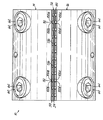
また、図7および図8は、ノズル10が組み立てられたときの、接着剤シム板54と、第1および第2空気シム板50,80と、第1および第2の端部板14,16との相対的な位置を示している。第1空気シム板50は、第1の端部板14を越えて延在し、関連する底部縁部98aは、第1の端部板14の底部縁部200から間隔を隔てている。また、底部縁部98aは、接着剤シム板54の底部縁部138をわずかに越えて突出して延びている。同様に、第2空気シム板80は、第2の端部板16を越えて延在し、関連する底部縁部98bは、第2の端部板16の底部縁部202から間隔を隔てている。この構成のために、底部縁部200,202は、関連する第1および第2空気シム板50,80における空気スロット100(図3)の部分を横切って延びている。底部縁部200,202の位置は、テーパ付き部材110の終端部112におおよそ対応している。
7 and 8 show the
例えば、図9および図10に示すように、第2空気シム板80は、第2の表面22と第2の端部板16との間に配置され、終端部112は、底部縁部202をわずかに越えて延びている。第1空気シム板50と第1の端部板14とは、同様な方法で配置されている。それぞれの空気スロット100が形成する空気通路は、関連する空気入口114(図3)から、関連する空気出口118へと延びており、加圧プロセス空気を1又は複数の液体出口158に向けて導く。
For example, as shown in FIGS. 9 and 10, the second
変形例による実施形態においては、第1および第2空気シム板50,80のうち、一方又は両方は、関連する底部縁部98a,98bが、第1の端部板14における底部縁部200又は第2の端部板16における底部縁部202に対して実質的に面一になるように配置されている。また、第1および第2のシム板50,80は、テーパ付き部材110の終端部112が、平面120(図3)において、関連する底部縁部98a,98bと実質的に整列されるように設計される。例えば、図12は、そうした構造を有する第3の空気シム板220を示しており、第1空気シム板50と同様な構造には、対応する参照符号を付している。従って、第3の空気シム板220は、ここでも、収束する対をなす空気スロット100a,100bを具備し、それぞれの空気入口114a,114bと、それぞれの空気出口118a,118bを有している。図13は、ノズル10における第1空気シム板50と置換したとき、接着剤シム板54および第1の端部板14に対して、第3の空気シム板220が配置される方法を示している。第3の空気シム板220と実質的に同一の構造を有する第4の空気シム板230が、第2空気シム板80(図8)の代わりに置換される。第4の空気シム板230は、第3の空気シム板220が第1の端部板14に対して配置されるのと実質的に同じ方法で、第2の端部板16に対して配置される。
In an alternative embodiment, one or both of the first and second
ノズル10は、第1および第2空気シム板50,80に代えて、第3および第4の空気シム板220,230が用いられているかどうかにかかわらず、同じ原理で動作する。再び、図10に示した実施形態を参照すると、接着剤シム板54は、それぞれの液体スロット136が、第1空気シム板50における一対の空気スロット100a,100bと、第2空気シム板80における一対の空気スロット100c,100dとの間に概略配置されるように位置決めされる。その結果、4つの空気スロット100a,100b,100c,100d(および、それらに対応する空気通路および空気出口118a,118b,118c,118d)は、それぞれの液体スロット136(および、対応する液体出口158)に関連している。図11は、この観点をさらに詳しく示しており、空気出口118と液体出口158との符号は、図面を明瞭にするために記していない。図11Aは、変形例による実施形態を示しており、第1空気シム板50からテーパ付き部材110を除去した点を除いて、ノズル10は前述のように構成されている。従って、3つの空気スロットが、それぞれの液体出口に関連している。もちろん、3つの空気スロットの設計は、第2空気シム板80からテーパ付き部材110を取り除くことによって達成されている。図11Bは、さらに別の実施形態によるノズル10を示しており、第1および第2空気シム板50,80の両方からテーパ付き部材110を除去した点を除いて、前述のように構成されている。従って、この実施形態においては、2つの空気スロット又は通路が、それぞれの液体スロットと関連する。
The
従って、吐出動作中には、上述したように、加圧液体接着剤は、接着剤シム板54における液体スロット136の液体入口156に供給される。液体スロット136は、加圧液体接着剤を、液体出口158を通して接着剤フィラメントとして放出する。接着剤フィラメントは、縦方向210に対するノズル10の構成に起因して、ノズル10を通過する基板(図示せず)の縦方向210(図6)に、わずかに斜めに放出される。同時に、加圧プロセス空気は、第1および第2空気シム板50,80における空気スロット100の空気入口114に供給される。空気スロット100によって形成された空気通路は、加圧プロセス空気を、液体スロット136から放出された接着剤フィラメントに向ける。それぞれのグループの4つの空気スロット100a,100b,100c,100dは、関連する液体スロット136の下方に乱流の領域を形成し、フィラメントをランダム方向に行き来させる。例えば、接着剤フィラメントは、“ウェブ方向”、すなわち、縦方向210に対して実質的に平行な方向と、“交差ウェブ方向”、すなわち、縦方向210に対して実質的に垂直な方向との両方において、行き来して動かされる。ノズル10のほとんどの動きは、ウェブ方向において生じる。そうして、最終的には、接着剤フィラメントは、概略縦方向210に沿ったランダムパターンにて、基板上に付着する。
Accordingly, during the dispensing operation, the pressurized liquid adhesive is supplied to the
本出願人は、加圧プロセス空気を、液体出口158を含む平面に対して、異なる角度に沿って、接着剤フィラメントに向けて導くことで、ノズル10は改良させた間欠性能を達成できることを見つけた。特に、非対称の構成によれば、加圧プロセス空気は、迅速且つ効果的に、吐出サイクルの間において、接着剤フィラメントを“破断”させて、輪郭が明確なカットオフ縁部およびカットオン縁部を備えた付着パターンを提供する。しかしながら、吐出サイクル中には、同一の速度の加圧プロセス空気が、接着剤フィラメントを破壊させずに行き来させて、ランダムに動かす。不都合な副作用(例えば、“飛沫”)は、しばしば、輪郭が明瞭なカットオフおよびカットオン縁部を提供するのに必要な速度に関連し、従って、減少又は実質的に解消される。
Applicants have found that the
輪郭が明瞭なカットオフおよびカットオン縁部の生産を助ける別の特徴は、接着剤シム板54に対する第2空気シム板80の構成である。より詳しくは、第2空気シム板80は、加圧プロセス空気を液体出口158(図5)の直近に導くように構成されている。角度θ1(図8)および底部縁部138に向かう底部縁部98bの近接のためである。この構成によれば、加圧プロセス空気は、液体出口158から放出されると直ちに、接着剤フィラメントに衝突する。従来の構成においては、加圧プロセス空気は、液体出口158から離された位置にて、接着剤フィラメントに衝突する。
Another feature that helps produce a well-defined cut-off and cut-on edge is the configuration of the second
当業者は認識するだろうが、上述した第1および第2空気シム板50,80と、接着剤シム板54との構成は、加圧プロセス空気を接着剤フィラメントに対して導く方法を示した単なる一例である。従って、第1空気シム板50は、接着剤シム板54に対して平行(すなわち、相対的に0度の角度)であると説明したけれども、第1空気シム板50は、代替的に、接着剤シム板54に対して異なる角度に配置することもできる。これを達成するには、上述したように、楔形状の分離シム板(図示せず)を使用する。非対称の構成を維持するためには、接着剤シム板54に対する第1空気シム板50の角度を、接着剤シム板54に対する第2空気シム板80の角度とは異なるように保持する。
Those skilled in the art will recognize that the configuration of the first and second
非対称の構成に加えて、対における空気スロット100のグループは、吐出サイクルの間において、接着剤フィラメントを有効に細くして“破断”する加圧プロセス空気の能力を高める。加圧プロセス空気の2つの流れは、接着剤フィラメントの両側に向けて導かれ、接着剤の迅速なカットオフを助ける。しかしながら、第1および第2空気シム板50,80のうち、一方又は両方は、対に配置される空気スロット100無しに、代替的に設計してもよいことを認識されたい。例えば、不図示の別の実施形態においては、第1又は第2空気シム板50,80のうちの一方は、テーパ付き部材112を含まない空気シム板で置換することができる。そうした代替的な空気シム板におけるそれぞれの空気スロット100は、液体出口158の1つに整列され、(1つは代替的な空気シム板の、2つは残りの第1又は第2空気シム板50,80の)3つの空気スロット100は、それぞれの液体出口158に関連付けられる。そうした構成によれば、接着剤フィラメントの箇所に向けられた、加圧プロセス空気の速度が高められ、接着剤の高い吐出圧力、流速などにおいて、不都合な副作用(例えば、飛沫)無しに、迅速なカットオフを達成する。別の実施形態においては、第1および第2空気シム板50,80の両方は、上述した代替的な空気シム板に置換される。
In addition to the asymmetric configuration, the group of
図14は、別の実施形態によるノズル232を示した底面図であって、複数の、例えば3枚の板から構成されている。一連の空気出口234と液体出口236とを形成している複数のスロットが、中央の板238に収容されている。出口234を有する空気スロットは、それぞれの液体出口236の反対側にある空気出口234から放出された空気流が、前述した方法で、略非対称に導かれるように構成されている。例えば、接着剤フィラメントの片側に放出される空気流は、液体出口236から放出され、フィラメント放出方向に対して略平行であり、一方、液体出口236の反対側にある空気出口234から放出された空気は、放出されたフィラメントに向けて、大きな角度に向けられる。外側板240,242は、両者の間に、中央板をサンドイッチにしている。
FIG. 14 is a bottom view showing a
本発明について、1又は複数の実施形態の説明によって例示したけれども、また、実施形態は詳細であると考えられるように説明したけれども、特許請求の範囲の範囲をそうした詳細に制限又は限定する意図はない。追加的な利点および変形は、当業者に容易に明らかになる。例えば、図6は、1つの構成によるノズル10を縦方向210に示しているけれども、ノズル10は、代替的に、縦方向210が逆方向になるように(例えば、図6における右側から左側に)配置してもよい。そうした実施形態においては、接着剤シム板54は、縦方向に対してわずかに斜めの角度に接着剤フィラメントを放出する。本願において説明した、様々な観点および特徴は、ユーザの要望に応じて、単独で、又は、任意の組み合わせにて使用される。従って、本発明は、その広い観点においては、特定の詳細、代表的な装置および方法、および、図示して説明した例に限定されない。従って、一般的な発明の概念の範囲又は精神から逸脱せずに、そうした詳細から出発することができる。
Although the invention has been illustrated by the description of one or more embodiments, and the embodiments have been described in detail, it is not intended to limit or limit the scope of the claims to such details. Absent. Additional advantages and modifications will be readily apparent to those skilled in the art. For example, although FIG. 6 shows the
Claims (26)
加圧プロセス空気を受けて導くようになっている複数の空気スロットをそれぞれが備える前記第1空気シム板および第2空気シム板と、
前記第1空気シム板および第2空気シム板の間に配置される接着剤シム板であって、該接着剤シム板は、加圧液体接着剤を受けて液体接着剤フィラメントを放出するようになっている複数の液体スロットを有し、該加圧プロセス空気は前記スロットによって導かれ、前記加圧液体接着剤のフィラメントをランダムパターンで前記液体スロットから吐出する接着剤シム板とを備え、
前記第1空気シム板における前記空気スロットは前記接着剤シム板に対して第1の角度に沿って加圧プロセス空気を導くように構成され、前記第2空気シム板における前記空気スロットは前記接着剤シム板に対して第2の角度に沿って加圧プロセス空気を導くように構成され、前記第1の角度は前記第2の角度とは異なっており、前記第1空気シム板および第2空気シム板は加圧プロセス空気を非対称的に接着剤フィラメントに向けて導くことを特徴とするノズル。 A nozzle for discharging a liquid adhesive filament in a random pattern, the nozzle comprising:
Said first air shim plate and second air shim plate each comprising a plurality of air slots adapted to receive and direct pressurized process air;
An adhesive shim plate disposed between the first air shim plate and the second air shim plate, wherein the adhesive shim plate receives a pressurized liquid adhesive and releases a liquid adhesive filament. A plurality of liquid slots, wherein the pressurized process air is guided by the slots and includes an adhesive shim plate that discharges filaments of the pressurized liquid adhesive from the liquid slots in a random pattern;
The air slot in the first air shim plate is configured to direct pressurized process air along a first angle with respect to the adhesive shim plate, and the air slot in the second air shim plate is the adhesive Configured to direct pressurized process air along a second angle with respect to the agent shim plate, wherein the first angle is different from the second angle, and the first air shim plate and the second air shim plate A nozzle characterized in that the air shim plate guides the pressurized process air asymmetrically toward the adhesive filament.
該第1の角度はほぼ0度であって、前記第1空気シム板は、前記接着剤シム板に対してほぼ平行であることを特徴とするノズル。 The nozzle according to claim 1,
The nozzle according to claim 1, wherein the first angle is approximately 0 degrees, and the first air shim plate is substantially parallel to the adhesive shim plate.
前記ノズルは、さらに、前記第1空気シム板と前記接着剤シム板との間に配置された分離シム板を備えていることを特徴とするノズル。 The nozzle according to claim 2,
The nozzle further includes a separation shim plate disposed between the first air shim plate and the adhesive shim plate.
該第2の角度は、約40度から約90度であることを特徴とするノズル。 The nozzle according to claim 2,
The nozzle characterized in that the second angle is about 40 degrees to about 90 degrees.
前記ノズル本体は、互いの方向にほぼ一つにまとまるような第1の表面および第2の表面を有し、前記接着剤シム板と前記第1空気シム板とはほぼ平行に配置されるように前記第1の表面に結合され、前記第2空気シム板はほぼ平行に配置されるように前記第2の表面に結合されていることを特徴とするノズル。 The nozzle according to claim 1,
The nozzle body has a first surface and a second surface that are substantially united in the direction of each other, and the adhesive shim plate and the first air shim plate are arranged substantially parallel to each other. The nozzle is coupled to the first surface, and the second air shim plate is coupled to the second surface so as to be disposed substantially in parallel.
前記ノズルは、さらに、前記第1空気シム板と前記接着剤シム板との間に配置された分離シム板を備えていることを特徴とするノズル。 The nozzle according to claim 5,
The nozzle further includes a separation shim plate disposed between the first air shim plate and the adhesive shim plate.
前記ノズルは、さらに、
前記ノズル本体における前記第1の表面に固定される第1の端部板であって、前記第1空気シム板と前記接着剤シム板とが、前記第1の端部板と前記ノズル本体との間に配置されている上記第1の端部板と、
前記ノズル本体における前記第2の表面に固定される第2の端部板であって、前記第2空気シム板が、前記第2の端部板と前記ノズル本体との間に配置されている上記第2の端部板と、
前記第1の表面と第2の表面との間に配置された上面を具備し、前記上面から前記第1の表面へ加圧プロセス空気を導くための少なくとも1つの空気供給通路と、前記上面から前記第2の表面へ加圧プロセス空気を導くための少なくとも1つのプロセス空気供給通路と、前記上面から前記第1の表面へ加圧液体接着剤を導くための少なくとも1つの液体供給通路とを備え、
前記第1の端部板および第2の端部板は、それぞれの分配通路を形成し、関連する第1の表面または第2の表面から、関連する第1空気シム板または第2空気シム板における前記空気スロットへ加圧プロセス空気を導くことを特徴とするノズル。 The nozzle according to claim 5,
The nozzle further comprises:
A first end plate fixed to the first surface of the nozzle body, wherein the first air shim plate and the adhesive shim plate are the first end plate and the nozzle body. The first end plate disposed between; and
A second end plate fixed to the second surface of the nozzle body, wherein the second air shim plate is disposed between the second end plate and the nozzle body. The second end plate;
An upper surface disposed between the first surface and the second surface, at least one air supply passage for directing pressurized process air from the upper surface to the first surface, and from the upper surface At least one process air supply passage for directing pressurized process air to the second surface; and at least one liquid supply passage for directing pressurized liquid adhesive from the top surface to the first surface. ,
The first end plate and the second end plate form a respective distribution passage, and from the associated first surface or second surface, the associated first air shim plate or second air shim plate. A nozzle for directing pressurized process air to the air slot in
前記接着剤シム板は、反対側の端部と、前記液体スロットとを具備し、前記接着剤シム板の中央部分から前記反対側の端部に向けて、漸進的に、外方へ傾いていることを特徴とするノズル。 The nozzle according to claim 1,
The adhesive shim plate includes an opposite end portion and the liquid slot, and is gradually inclined outward from the central portion of the adhesive shim plate toward the opposite end portion. Nozzle characterized by being.
前記液体スロットのそれぞれは、前記第1空気シム板における一対の前記空気スロットと、ほぼ前記第2空気シム板における一対の前記空気スロットとの間に配置され、それにより、4つの前記空気スロットをそれぞれの液体スロットに関連させることを特徴とするノズル。 The nozzle according to claim 1,
Each of the liquid slots is disposed between a pair of the air slots in the first air shim plate and a pair of the air slots in the second air shim plate so that the four air slots are arranged. A nozzle characterized in that it is associated with each liquid slot.
前記液体スロットのそれぞれは、前記第1空気シム板における一対の前記空気スロットと、ほぼ前記第2空気シム板における前記空気スロットの1つとの間に配置され、それにより、3つの前記空気スロットをそれぞれの液体スロットに関連させることを特徴とするノズル。 The nozzle according to claim 1,
Each of the liquid slots is disposed between a pair of the air slots in the first air shim plate and approximately one of the air slots in the second air shim plate, thereby providing three air slots. A nozzle characterized in that it is associated with each liquid slot.
前記液体スロットのそれぞれは、前記第1空気シム板における前記空気スロットの1つと、ほぼ前記第2空気シム板における前記空気スロットの1つとの間に配置され、それにより、2つの前記空気スロットをそれぞれの液体スロットに関連させることを特徴とするノズル。 The nozzle according to claim 1,
Each of the liquid slots is disposed between one of the air slots in the first air shim plate and approximately one of the air slots in the second air shim plate, thereby connecting the two air slots. A nozzle characterized in that it is associated with each liquid slot.
前記空気スロットのそれぞれは、空気入口と、空気出口とを具備し、それぞれの対における前記空気スロットは、互いに向けて収束しており、前記空気入口は、それぞれの対における前記空気出口に比べて遠くに離れていることを特徴とするノズル。 The nozzle according to claim 9,
Each of the air slots comprises an air inlet and an air outlet, the air slots in each pair converging towards each other, and the air inlet is compared to the air outlet in each pair A nozzle characterized by being far away.
前記第1空気シム板および第2空気シム板は、前記空気スロットのそれぞれの対の間に形成されたそれぞれのテーパ付き部材を具備し、前記第1空気シムおよび第2空気シム板はさらに、底部縁部を具備し、前記テーパ付き部材は、前記底部縁部を含む平面の上方にて終端していることを特徴とするノズル。 The nozzle according to claim 12, wherein
The first air shim plate and the second air shim plate include respective tapered members formed between the respective pairs of the air slots, and the first air shim and the second air shim plate further include: A nozzle comprising a bottom edge, wherein the tapered member terminates above a plane including the bottom edge.
複数の液体接着剤フィラメントをそれぞれ放出するように構成された複数の液体出口と、
第1の複数の空気通路であって、前記第1の複数の空気通路におけるそれぞれの空気通路は、前記液体出口の1つに関連し、前記関連する液体出口を含む平面に対して、第1の角度に沿って、加圧プロセス空気を導くように構成されている第1の複数の空気通路と、
第2の複数の空気通路であって、前記第2の複数の空気通路におけるそれぞれの空気通路は、前記液体出口の1つに関連し、前記関連する液体出口を含む平面に対して、第2の角度に沿って、加圧プロセス空気を導くように構成されている第2の複数の空気通路と、
少なくとも1つの前記第1の複数の空気通路と、少なくとも1つの前記第2の複数の空気通路とは、前記液体出口の1つにおける反対側にあり、
前記第1の角度は前記第2の角度とは異なっており、該加圧プロセス空気は前記第1および第2の複数の空気通路から、それぞれの液体接着剤フィラメントに向かってランダムパターンを作るように非対称に導かれることを特徴とするノズル。 A nozzle that discharges a plurality of liquid adhesive filaments in a random pattern, the nozzle comprising:
A plurality of liquid outlets configured to each discharge a plurality of liquid adhesive filaments;
A first plurality of air passages, each air passage in the first plurality of air passages being associated with one of the liquid outlets and first relative to a plane including the associated liquid outlet. A first plurality of air passages configured to direct pressurized process air along an angle of
A second plurality of air passages, each air passage in the second plurality of air passages being associated with one of the liquid outlets and second relative to a plane including the associated liquid outlet. A second plurality of air passages configured to direct pressurized process air along an angle of
At least one of the first plurality of air passages and at least one of the second plurality of air passages are on opposite sides of one of the liquid outlets;
The first angle is different from the second angle so that the pressurized process air creates a random pattern from the first and second air passages toward the respective liquid adhesive filaments. A nozzle characterized by being guided asymmetrically.
前記複数の液体出口は、列をなして配置され、前記第1の複数の空気通路および第2の複数の空気通路は、前記列を含む平面とは反対側に配置されていることを特徴とするノズル。 The nozzle according to claim 14,
The plurality of liquid outlets are arranged in rows, and the first plurality of air passages and the second plurality of air passages are arranged on a side opposite to a plane including the rows. Nozzle to do.
前記第1の複数の空気通路および第2の複数の空気通路と、前記複数の液体出口とは、直列に配置されていることを特徴とするノズル。 The nozzle according to claim 14,
The first plurality of air passages, the second plurality of air passages, and the plurality of liquid outlets are arranged in series.
前記第1の複数の空気通路の1つは、前記1つの液体出口における第1の側にあり、前記第2の複数の空気通路の2つは、前記1つの液体出口における第2の反対側にあり、それにより、3つの空気通路をそれぞれの前記液体出口に関連させることを特徴とするノズル。 The nozzle according to claim 14,
One of the first plurality of air passages is on a first side of the one liquid outlet, and two of the second plurality of air passages are a second opposite side of the one liquid outlet. A nozzle characterized in that three air passages are associated with each said liquid outlet.
前記第1の複数の空気通路の2つは、前記1つの液体出口における第1の側にあり、前記第2の複数の空気通路の2つは、前記1つの液体出口における第2の反対側にあり、それにより、4つの空気通路をそれぞれの前記液体出口に関連させることを特徴とするノズル。 The nozzle according to claim 14,
Two of the first plurality of air passages are on a first side of the one liquid outlet, and two of the second plurality of air passages are a second opposite side of the one liquid outlet. A nozzle, characterized in that four air passages are associated with each said liquid outlet.
前記第1の複数の空気通路の1つは、前記1つの液体出口における第1の側にあり、前記第2の複数の空気通路の1つは、前記1つの液体出口における第2の反対側にあり、それにより、2つの空気通路をそれぞれの前記液体出口に関連させることを特徴とするノズル。 The nozzle according to claim 14,
One of the first plurality of air passages is on a first side of the one liquid outlet, and one of the second plurality of air passages is a second opposite side of the one liquid outlet. A nozzle, characterized in that two air passages are associated with each said liquid outlet.
第1の表面および第2の表面を有するノズル本体であって、前記複数の液体出口が前記第1の表面および第2の表面の間に形成されている、上記ノズル本体と、
前記第1の表面に近接して前記ノズル本体に結合された第1の端部板であって、該第1の複数の空気通路は前記ノズル本体と前記第1の端部板との間に形成されている第1の端部板と、
前記第2の表面に近接して前記ノズル本体に結合された第2の端部板であって、該第2の複数の空気通路は前記ノズル本体と前記第1の端部板との間に形成されている第2の端部板とを備えていることを特徴とするノズル。 The nozzle according to claim 14, wherein the nozzle further comprises:
A nozzle body having a first surface and a second surface, wherein the plurality of liquid outlets are formed between the first surface and the second surface;
A first end plate coupled to the nozzle body proximate to the first surface, the first plurality of air passages between the nozzle body and the first end plate; A first end plate being formed;
A second end plate coupled to the nozzle body proximate to the second surface, wherein the second plurality of air passages are between the nozzle body and the first end plate. A nozzle comprising: a second end plate formed.
前記ノズル本体に結合された接着剤シム板であって、前記接着剤シム板は前記複数の液体出口を形成する複数の液体スロットを有している接着剤シム板を備えていることを特徴とするノズル。 The nozzle according to claim 20, wherein the nozzle further comprises:
An adhesive shim plate coupled to the nozzle body, wherein the adhesive shim plate includes an adhesive shim plate having a plurality of liquid slots forming the plurality of liquid outlets. Nozzle to do.
縦方向に沿って基板を動かす段階と、
複数の液体出口から、複数の接着剤フィラメントを放出する段階と、
関連する液体出口を含む平面に対して、第1の角度に沿って、複数の接着剤フィラメントに向けて加圧プロセス空気を導く段階と、
関連する液体出口の反対側にある関連する液体出口を含む平面に対して、第2の角度に沿って、複数の接着剤フィラメントに向けて加圧プロセス空気を導く段階であって、該第2の角度は第1の角度と異なっていて、加圧プロセス空気を複数の接着剤フィラメントに向けて非対称に導く段階と、
複数の接着剤フィラメントを基板上にランダムパターンにて付着させる段階と、
を備えていることを特徴とする方法。 A method of discharging a plurality of adhesive filaments on a substrate in a random pattern, the method comprising:
Moving the substrate along the vertical direction;
Discharging a plurality of adhesive filaments from a plurality of liquid outlets;
Directing the pressurized process air toward a plurality of adhesive filaments along a first angle relative to a plane including an associated liquid outlet;
Directing pressurized process air toward a plurality of adhesive filaments along a second angle relative to a plane containing the associated liquid outlet opposite the associated liquid outlet, the second The angle of is different from the first angle and directs the pressurized process air asymmetrically toward the plurality of adhesive filaments;
Attaching a plurality of adhesive filaments on the substrate in a random pattern;
A method characterized by comprising:
複数の接着剤フィラメントに向けて導かれる加圧プロセス空気を用いて、液体出口の下方に乱気流の領域を形成する段階と、
乱流の領域を通過するように複数の接着剤フィラメントを導いて、複数の接着剤フィラメントをランダム方向に移動させる段階と、
を備えていることを特徴とする方法。 23. The method of claim 22, further comprising:
Forming a region of turbulence below the liquid outlet using pressurized process air directed toward a plurality of adhesive filaments;
Directing a plurality of adhesive filaments to pass through a region of turbulence and moving the plurality of adhesive filaments in a random direction;
A method characterized by comprising:
第1の角度に沿って加圧プロセス空気を導く段階は、空気の1つの流れを導く段階をさらに備え、第2の角度に沿って加圧プロセス空気を導く段階は、空気の2つの流れを導く段階をさらに備え、それにより合計3つの空気の流れを、それぞれの前記接着剤フィラメントに向けて導くことを特徴とする方法。 23. The method of claim 22, comprising
The step of directing the pressurized process air along the first angle further comprises the step of directing one flow of air, and the step of directing the pressurized process air along the second angle comprises two flows of air. A method further comprising the step of directing a total of three air streams toward each of said adhesive filaments.
第1の角度に沿って加圧プロセス空気を導く段階は、空気の2つの流れを導く段階をさらに備え、第2の角度に沿って加圧プロセス空気を導く段階は、空気の2つの流れを導く段階をさらに備え、それにより、合計4つの空気の流れをそれぞれの前記接着剤フィラメントに向けて導くことを特徴とする方法。 23. The method of claim 22, comprising
The step of directing the pressurized process air along the first angle further comprises the step of directing the two flows of air, and the step of directing the pressurized process air along the second angle includes the two flows of air. A method further comprising directing a total of four air streams toward each of said adhesive filaments.
第1の角度に沿って加圧プロセス空気を導く段階は、空気の1つの流れを導く段階をさらに備え、第2の角度に沿って加圧プロセス空気を導く段階は、空気の1つの流れを導く段階をさらに備え、それにより合計2つの空気の流れをそれぞれの前記接着剤フィラメントに向けて導くことを特徴とする方法。 23. The method of claim 22, comprising
Directing the pressurized process air along the first angle further comprises directing a single flow of air, and directing the pressurized process air along the second angle includes directing the single flow of air. A step of directing, whereby a total of two air streams are directed toward each of said adhesive filaments.
Applications Claiming Priority (2)
| Application Number | Priority Date | Filing Date | Title |
|---|---|---|---|
| US12/102501 | 2008-04-14 | ||
| US12/102,501 US8074902B2 (en) | 2008-04-14 | 2008-04-14 | Nozzle and method for dispensing random pattern of adhesive filaments |
Publications (2)
| Publication Number | Publication Date |
|---|---|
| JP2009291780A true JP2009291780A (en) | 2009-12-17 |
| JP5502361B2 JP5502361B2 (en) | 2014-05-28 |
Family
ID=40827492
Family Applications (1)
| Application Number | Title | Priority Date | Filing Date |
|---|---|---|---|
| JP2009097756A Active JP5502361B2 (en) | 2008-04-14 | 2009-04-14 | Nozzle and method for discharging adhesive filament in random pattern |
Country Status (7)
| Country | Link |
|---|---|
| US (3) | US8074902B2 (en) |
| EP (1) | EP2110184B1 (en) |
| JP (1) | JP5502361B2 (en) |
| CN (1) | CN101559410B (en) |
| BR (1) | BRPI0900971B1 (en) |
| ES (1) | ES2454273T3 (en) |
| MX (2) | MX354271B (en) |
Cited By (1)
| Publication number | Priority date | Publication date | Assignee | Title |
|---|---|---|---|---|
| JP2017535460A (en) * | 2014-11-26 | 2017-11-30 | イリノイ トゥール ワークス インコーポレイティド | Laminated nozzle with thick plate |
Families Citing this family (27)
| Publication number | Priority date | Publication date | Assignee | Title |
|---|---|---|---|---|
| US7798434B2 (en) | 2006-12-13 | 2010-09-21 | Nordson Corporation | Multi-plate nozzle and method for dispensing random pattern of adhesive filaments |
| US8074902B2 (en) | 2008-04-14 | 2011-12-13 | Nordson Corporation | Nozzle and method for dispensing random pattern of adhesive filaments |
| DE102009034687B4 (en) * | 2009-07-24 | 2017-03-30 | Windmöller & Hölscher Kg | Device and method for providing workpieces or webs with glue |
| US8640641B2 (en) | 2010-07-02 | 2014-02-04 | Nordson Corporation | Multi-slot applicator with automatic closing function |
| PT2719518T (en) * | 2011-09-02 | 2016-09-19 | Rkw Se | Method for stretching a sheet of film |
| US8986474B2 (en) | 2012-01-11 | 2015-03-24 | Nordson Corporation | Method of manufacturing a composite superabsorbent core structure |
| WO2015126761A1 (en) | 2014-02-24 | 2015-08-27 | Nanofiber, Inc. | Melt blowing die, apparatus and method |
| US9849480B2 (en) | 2014-11-26 | 2017-12-26 | Illinois Tool Works Inc. | Laminated nozzle with thick plate |
| US9446422B2 (en) * | 2015-02-10 | 2016-09-20 | Nordson Corporation | Adhesive dispensing module and method of spraying a plurality of droplets of a liquid adhesive |
| US10130972B2 (en) * | 2015-09-09 | 2018-11-20 | Illinois Tool Works Inc. | High speed intermittent barrier nozzle |
| US10989888B2 (en) * | 2016-02-02 | 2021-04-27 | Ofs Fitel, Llc | Flexible ribbon structure and method for making |
| CN109843449B (en) | 2016-09-08 | 2022-02-18 | 诺信公司 | Remote metering station |
| US10864544B2 (en) * | 2016-09-08 | 2020-12-15 | Nordson Corporation | Applicator with at least one pump having an integrated drive |
| US10695779B2 (en) | 2016-09-08 | 2020-06-30 | Nordson Corporation | Applicator having active backpressure control devices |
| DE102016014269A1 (en) | 2016-11-30 | 2018-05-30 | Dürr Systems Ag | Nozzle device with at least two nozzle plates and at least three openings |
| DE102016014270A1 (en) * | 2016-11-30 | 2018-05-30 | Dürr Systems Ag | A nozzle device for emitting two approaching jets of a delivery medium |
| JP7447018B2 (en) | 2018-05-03 | 2024-03-11 | エイブリィ・デニソン・コーポレイション | Adhesive laminate and method for manufacturing adhesive laminate |
| DE102019106146A1 (en) * | 2019-03-11 | 2020-09-17 | Illinois Tool Works Inc. | NOZZLE ARRANGEMENT FOR APPLYING FLUIDS, SYSTEM WITH SUCH NOZZLE ARRANGEMENT AND METHOD FOR APPLYING FLUIDS |
| JP2021154195A (en) * | 2020-03-26 | 2021-10-07 | ノードソン コーポレーションNordson Corporation | Nozzle, adhesive application head, adhesive application device, and diaper manufacturing method |
| EP4171841A1 (en) * | 2020-06-24 | 2023-05-03 | Nordson Corporation | Dual dispensing nozzle and method of using the same |
| MX2023001703A (en) | 2020-09-01 | 2023-03-09 | Procter & Gamble | Dispensing package and method for controlled delivery of a viscous composition. |
| DE202020004080U1 (en) * | 2020-09-29 | 2020-10-27 | Franz-Josef Schnödewind | Grooved sheet for externally mixing two-fluid nozzles, in particular as a slot nozzle for spraying fluids over a large area |
| US20230140800A1 (en) * | 2020-10-28 | 2023-05-04 | Lg Energy Solution, Ltd. | Slot Die Coater |
| US20220258197A1 (en) * | 2021-02-15 | 2022-08-18 | Harrington & Associates, Inc. | Adhesive dispensing nozzle |
| US11583887B2 (en) * | 2021-04-30 | 2023-02-21 | Nordson Corporation | Slot nozzle for adhesive applicators |
| USD986302S1 (en) * | 2021-04-30 | 2023-05-16 | Nordson Corporation | Slot nozzle assembly |
| WO2023192148A1 (en) | 2022-03-30 | 2023-10-05 | Nordson Corporation | Full cover/fine lines spray application |
Citations (13)
| Publication number | Priority date | Publication date | Assignee | Title |
|---|---|---|---|---|
| US3981650A (en) * | 1975-01-16 | 1976-09-21 | Beloit Corporation | Melt blowing intermixed filaments of two different polymers |
| JPH06198239A (en) * | 1992-12-31 | 1994-07-19 | San Tool:Kk | Spray coating device for curtain fiber like adhesive |
| JPH08501974A (en) * | 1992-07-08 | 1996-03-05 | ノードソン コーポレーション | Split slot die for fiber air spray |
| JPH08243461A (en) * | 1995-03-06 | 1996-09-24 | Santsuule:Kk | Curtain-like spray coating method, and coating nozzle apparatus in curtain-like spray coating apparatus |
| JPH11156268A (en) * | 1997-09-29 | 1999-06-15 | Illinois Tool Works Inc <Itw> | Fluid applying device and method therefor |
| JPH11347459A (en) * | 1998-06-10 | 1999-12-21 | Sun Tool:Kk | Contactless intermittent spray coating applicator for hot melt adhesive |
| JP2002102765A (en) * | 2000-09-29 | 2002-04-09 | Suntool Corp | Method and device for curtain fiberlike spray coating |
| JP2002512122A (en) * | 1998-04-17 | 2002-04-23 | ノードソン コーポレーション | Method and apparatus for applying a controlled pattern of fibrous material to a moving support |
| JP2002126596A (en) * | 2000-10-20 | 2002-05-08 | Nordson Kk | Method and apparatus for applying liquid to substrate such as sheet |
| JP2002361123A (en) * | 2001-03-22 | 2002-12-17 | Nordson Corp | All-round distribution system for pushing out filamentous liquid by support of air |
| WO2003086655A1 (en) * | 2002-04-12 | 2003-10-23 | Nordson Corporation | Module, nozzle and method for dispensing controlled patterns of liquid material |
| JP2004154665A (en) * | 2002-11-06 | 2004-06-03 | Suntool Corp | Spray coating application method for hot melt adhesive and coating application nozzle device for hot melt adhesive spray coatingapplicator |
| JP2004195434A (en) * | 2002-12-20 | 2004-07-15 | Nordson Corp | Coated object of stitch-like pattern, coating method of viscous fluid material, coating device, and nozzle |
Family Cites Families (179)
| Publication number | Priority date | Publication date | Assignee | Title |
|---|---|---|---|---|
| US2031387A (en) | 1934-08-22 | 1936-02-18 | Schwarz Arthur | Nozzle |
| US2212448A (en) | 1935-06-08 | 1940-08-20 | Owens Corning Fiberglass Corp | Method and apparatus for the production of fibers from molten glass and similar meltable materials |
| US2297726A (en) | 1938-04-02 | 1942-10-06 | Thermo Plastics Corp | Method and apparatus for drying or the like |
| BE492010A (en) | 1948-11-05 | |||
| US2628386A (en) | 1952-04-29 | 1953-02-17 | Modern Plastic Machinery Corp | Web extrusion die |
| US3032008A (en) | 1956-05-07 | 1962-05-01 | Polaroid Corp | Apparatus for manufacturing photographic films |
| US3038202A (en) | 1959-01-28 | 1962-06-12 | Multiple Extrusions Inc | Method and apparatus for making multiple tube structures by extrusion |
| US3181738A (en) | 1960-11-04 | 1965-05-04 | Hartvig-Johansen Leif | Dispensing device |
| DE1132896B (en) | 1961-01-05 | 1962-07-12 | Bayer Ag | Process for the production of granular or cylindrical granulates |
| US3178770A (en) | 1962-01-19 | 1965-04-20 | Du Pont | Variable orifice extruder die |
| US3176345A (en) | 1962-06-25 | 1965-04-06 | Monsanto Co | Spinnerette |
| US3192563A (en) | 1962-06-25 | 1965-07-06 | Monsanto Co | Laminated spinneret |
| NL125332C (en) | 1962-06-25 | |||
| US3204290A (en) | 1962-12-27 | 1965-09-07 | Monsanto Co | Laminated spinneret |
| US3501805A (en) | 1963-01-03 | 1970-03-24 | American Cyanamid Co | Apparatus for forming multicomponent fibers |
| US3253301A (en) | 1963-01-14 | 1966-05-31 | Monsanto Co | Non-circular spinneret orifices |
| DE1435461C3 (en) | 1964-02-22 | 1978-04-06 | Fa. Carl Freudenberg, 6940 Weinheim | Spinneret for melt spinning sheets of thread |
| DE1584324A1 (en) | 1965-04-15 | 1969-12-18 | Schneider & Co | Device for the production of ceramic bodies |
| US3334792A (en) | 1966-05-19 | 1967-08-08 | Herculite Protective Fab | Adhesive applicator |
| DE1969216U (en) | 1966-10-24 | 1967-09-28 | Du Pont | SPIN PACK. |
| NL6801610A (en) | 1967-02-07 | 1968-08-08 | ||
| US3849241A (en) | 1968-12-23 | 1974-11-19 | Exxon Research Engineering Co | Non-woven mats by melt blowing |
| US3978185A (en) | 1968-12-23 | 1976-08-31 | Exxon Research And Engineering Company | Melt blowing process |
| US3613170A (en) | 1969-05-27 | 1971-10-19 | American Cyanamid Co | Spinning apparatus for sheath-core bicomponent fibers |
| US3755527A (en) | 1969-10-09 | 1973-08-28 | Exxon Research Engineering Co | Process for producing melt blown nonwoven synthetic polymer mat having high tear resistance |
| US3704198A (en) | 1969-10-09 | 1972-11-28 | Exxon Research Engineering Co | Nonwoven polypropylene mats of increased strip tensile strength |
| US3650866A (en) | 1969-10-09 | 1972-03-21 | Exxon Research Engineering Co | Increasing strip tensile strength of melt blown nonwoven polypropylene mats of high tear resistance |
| JPS5115124B1 (en) | 1971-05-04 | 1976-05-14 | ||
| BE787033A (en) | 1971-08-06 | 1973-02-01 | Solvay | |
| US3730662A (en) | 1971-12-01 | 1973-05-01 | Monsanto Co | Spinneret assembly |
| BE795841A (en) | 1972-02-25 | 1973-08-23 | Montedison Spa | PROCESS FOR PREPARING FIBERS FROM POLYMERIC MATERIALS, SUITABLE FOR THE PREPARATION OF PAPER PULP |
| US3801400A (en) | 1972-03-24 | 1974-04-02 | Celanese Corp | Varying density cartridge filters |
| US3806289A (en) | 1972-04-05 | 1974-04-23 | Kimberly Clark Co | Apparatus for producing strong and highly opaque random fibrous webs |
| US3825379A (en) | 1972-04-10 | 1974-07-23 | Exxon Research Engineering Co | Melt-blowing die using capillary tubes |
| US3847537A (en) | 1972-08-22 | 1974-11-12 | W Velie | Air-atomizing fuel burner |
| US3861850A (en) | 1972-09-05 | 1975-01-21 | Marvin E Wallis | Film forming head |
| DE2245820C2 (en) | 1972-09-19 | 1974-08-22 | Windmoeller & Hoelscher, 4540 Lengerich | Extrusion press for processing plastic, in particular thermoplastic or non-crosslinked elastomeric materials |
| US3803951A (en) | 1972-10-10 | 1974-04-16 | Corning Glass Works | Method of forming an extrusion die |
| US3920362A (en) | 1972-10-27 | 1975-11-18 | Jeffers Albert L | Filament forming apparatus with sweep fluid channel surrounding spinning needle |
| US4015964A (en) | 1973-03-30 | 1977-04-05 | Saint-Gobain Industries | Method and apparatus for making fibers from thermoplastic materials |
| US4015963A (en) | 1973-03-30 | 1977-04-05 | Saint-Gobain Industries | Method and apparatus for forming fibers by toration |
| US4052183A (en) | 1973-04-24 | 1977-10-04 | Saint-Gobain Industries | Method and apparatus for suppression of pollution in toration of glass fibers |
| FR2223318B1 (en) | 1973-03-30 | 1978-03-03 | Saint Gobain | |
| US3888610A (en) | 1973-08-24 | 1975-06-10 | Rothmans Of Pall Mall | Formation of polymeric fibres |
| US4100324A (en) | 1974-03-26 | 1978-07-11 | Kimberly-Clark Corporation | Nonwoven fabric and method of producing same |
| US3970417A (en) | 1974-04-24 | 1976-07-20 | Beloit Corporation | Twin triple chambered gas distribution system for melt blown microfiber production |
| US3942723A (en) | 1974-04-24 | 1976-03-09 | Beloit Corporation | Twin chambered gas distribution system for melt blown microfiber production |
| US3923444A (en) | 1974-05-03 | 1975-12-02 | Ford Motor Co | Extrusion die |
| US3954361A (en) | 1974-05-23 | 1976-05-04 | Beloit Corporation | Melt blowing apparatus with parallel air stream fiber attenuation |
| DD115206A5 (en) | 1974-07-13 | 1975-09-12 | Monforts Fa A | Fluidic OSC |
| US4052002A (en) | 1974-09-30 | 1977-10-04 | Bowles Fluidics Corporation | Controlled fluid dispersal techniques |
| NL7507443A (en) | 1975-06-23 | 1976-12-27 | Akzo Nv | MELTING EQUIPMENT. |
| US4185981A (en) | 1975-08-20 | 1980-01-29 | Nippon Sheet Glass Co.,Ltd. | Method for producing fibers from heat-softening materials |
| DE2614596C3 (en) | 1976-04-05 | 1980-03-13 | Vereinigte Glaswerke Gmbh, 5100 Aachen | Skimmer head for applying castable plastic layers on flat surfaces |
| US5035361A (en) | 1977-10-25 | 1991-07-30 | Bowles Fluidics Corporation | Fluid dispersal device and method |
| US4151955A (en) | 1977-10-25 | 1979-05-01 | Bowles Fluidics Corporation | Oscillating spray device |
| USRE33448E (en) | 1977-12-09 | 1990-11-20 | Fluidic oscillator and spray-forming output chamber | |
| US4277436A (en) | 1978-04-26 | 1981-07-07 | Owens-Corning Fiberglas Corporation | Method for forming filaments |
| US4231519A (en) | 1979-03-09 | 1980-11-04 | Peter Bauer | Fluidic oscillator with resonant inertance and dynamic compliance circuit |
| US4300876A (en) | 1979-12-12 | 1981-11-17 | Owens-Corning Fiberglas Corporation | Apparatus for fluidically attenuating filaments |
| US4359445A (en) | 1980-01-21 | 1982-11-16 | Owens-Corning Fiberglas Corporation | Method for producing a lofted mat |
| US4380570A (en) | 1980-04-08 | 1983-04-19 | Schwarz Eckhard C A | Apparatus and process for melt-blowing a fiberforming thermoplastic polymer and product produced thereby |
| US4340563A (en) | 1980-05-05 | 1982-07-20 | Kimberly-Clark Corporation | Method for forming nonwoven webs |
| US4798619A (en) * | 1980-06-02 | 1989-01-17 | American Cyanamid Co. | 2-(2-imidazolin-2-yl)-pyridines and quinolines and use of said compounds as herbicidal agents |
| US4414276A (en) | 1980-07-29 | 1983-11-08 | Teijin Limited | Novel assembly of composite fibers |
| US4457685A (en) | 1982-01-04 | 1984-07-03 | Mobil Oil Corporation | Extrusion die for shaped extrudate |
| US4468366A (en) | 1982-08-19 | 1984-08-28 | Corning Glass Works | Baffled laminated extrusion dies |
| US4526733A (en) | 1982-11-17 | 1985-07-02 | Kimberly-Clark Corporation | Meltblown die and method |
| EP0300120B1 (en) | 1983-03-23 | 1992-05-06 | B a r m a g AG | Spinnerette for melt-spinning filaments |
| JPS6086051A (en) | 1983-10-19 | 1985-05-15 | Nippon Sheet Glass Co Ltd | Manufacture of fiber |
| US4596364A (en) | 1984-01-11 | 1986-06-24 | Peter Bauer | High-flow oscillator |
| US4818464A (en) | 1984-08-30 | 1989-04-04 | Kimberly-Clark Corporation | Extrusion process using a central air jet |
| DE3506924A1 (en) | 1985-02-27 | 1986-09-04 | Reifenhäuser GmbH & Co Maschinenfabrik, 5210 Troisdorf | DEVICE FOR SPINNING MONOFILE THREADS FROM THERMOPLASTIC PLASTIC |
| FR2579516B1 (en) | 1985-04-01 | 1987-06-12 | Solvay | POWER SUPPLY FOR FLAT COEXTRUSION SECTOR |
| GB8509712D0 (en) | 1985-04-16 | 1985-05-22 | Elopak As | Fluid flow nozzle |
| US4694992A (en) | 1985-06-24 | 1987-09-22 | Bowles Fluidics Corporation | Novel inertance loop construction for air sweep fluidic oscillator |
| US4730197A (en) | 1985-11-06 | 1988-03-08 | Pitney Bowes Inc. | Impulse ink jet system |
| DE3543469A1 (en) | 1985-12-09 | 1987-06-11 | Henning J Claassen | SPRAYING HEAD FOR SPRAYING A THERMOPLASTIC PLASTIC, ESPECIALLY A MELTING ADHESIVE |
| US4889476A (en) | 1986-01-10 | 1989-12-26 | Accurate Products Co. | Melt blowing die and air manifold frame assembly for manufacture of carbon fibers |
| US4874451A (en) | 1986-03-20 | 1989-10-17 | Nordson Corporation | Method of forming a disposable diaper with continuous/intermittent rows of adhesive |
| US4818463A (en) | 1986-04-26 | 1989-04-04 | Buehning Peter G | Process for preparing non-woven webs |
| EP0265249B1 (en) | 1986-10-21 | 1993-03-10 | Mitsui Petrochemical Industries, Ltd. | Melt blow die |
| US4747986A (en) | 1986-12-24 | 1988-05-31 | Allied-Signal Inc. | Die and method for forming honeycomb structures |
| ES2042612T3 (en) | 1987-03-07 | 1993-12-16 | Fuller H B Licensing Financ | PROCEDURE FOR THE PERMANENT JOINING OF EXPANDABLE ELEMENTS IN THE FORM OF THREADS OR RIBBONS ON A SURFACE SUBSTRATE AS WELL AS USING IT FOR THE MANUFACTURE OF CURLED LEAF BAND SECTORS. |
| US4711683A (en) | 1987-03-09 | 1987-12-08 | Paper Converting Machine Company | Method and apparatus for making elastic diapers |
| US4746283A (en) | 1987-04-01 | 1988-05-24 | Hobson Gerald R | Head tooling parison adapter plates |
| USRE33481E (en) | 1987-04-23 | 1990-12-11 | Nordson Corporation | Adhesive spray gun and nozzle attachment |
| US4785996A (en) | 1987-04-23 | 1988-11-22 | Nordson Corporation | Adhesive spray gun and nozzle attachment |
| US4774109A (en) | 1987-07-21 | 1988-09-27 | Nordson Corporation | Method and apparatus for applying narrow, closely spaced beads of viscous liquid to a substrate |
| US4955547A (en) | 1987-09-02 | 1990-09-11 | Spectra Technologies, Inc. | Fluidic oscillating nozzle |
| US4905909A (en) | 1987-09-02 | 1990-03-06 | Spectra Technologies, Inc. | Fluidic oscillating nozzle |
| KR950001645B1 (en) | 1987-10-02 | 1995-02-27 | 바스프 코포레이션 | Profiled multi-component fibers and method and apparatus for making the same |
| US4983109A (en) | 1988-01-14 | 1991-01-08 | Nordson Corporation | Spray head attachment for metering gear head |
| US4923706A (en) | 1988-01-14 | 1990-05-08 | Thomas J. Lipton, Inc. | Process of and apparatus for shaping extrudable material |
| JP2660415B2 (en) | 1988-02-17 | 1997-10-08 | チッソ株式会社 | Sheath-core composite spinneret |
| US4812276A (en) | 1988-04-29 | 1989-03-14 | Allied-Signal Inc. | Stepwise formation of channel walls in honeycomb structures |
| US4949668A (en) | 1988-06-16 | 1990-08-21 | Kimberly-Clark Corporation | Apparatus for sprayed adhesive diaper construction |
| US5069853A (en) | 1988-06-17 | 1991-12-03 | Gencorp Inc. | Method of configuring extrudate flowing from an extruder die assembly |
| US5067885A (en) | 1988-06-17 | 1991-11-26 | Gencorp Inc. | Rapid change die assembly |
| US4960619A (en) | 1988-06-30 | 1990-10-02 | Slautterback Corporation | Method for depositing adhesive in a reciprocating motion |
| US4844003A (en) | 1988-06-30 | 1989-07-04 | Slautterback Corporation | Hot-melt applicator |
| US5114752A (en) | 1988-12-12 | 1992-05-19 | Nordson Corporation | Method for gas-aided dispensing of liquid materials |
| US5017116A (en) | 1988-12-29 | 1991-05-21 | Monsanto Company | Spinning pack for wet spinning bicomponent filaments |
| US5312500A (en) | 1989-01-27 | 1994-05-17 | Nippon Petrochemicals Co., Ltd. | Non-woven fabric and method and apparatus for making the same |
| US4918017A (en) | 1989-02-03 | 1990-04-17 | Bridgestone/Firestone, Inc. | Screen assembly for screening elastomeric material |
| US5160746A (en) | 1989-06-07 | 1992-11-03 | Kimberly-Clark Corporation | Apparatus for forming a nonwoven web |
| DE3927254A1 (en) | 1989-08-18 | 1991-02-21 | Reifenhaeuser Masch | METHOD AND SPINNING NOZZLE UNIT FOR THE PRODUCTION OF PLASTIC THREADS AND / OR PLASTIC FIBERS INTO THE PRODUCTION OF A SPINNING FLEECE FROM THERMOPLASTIC PLASTIC |
| US5013232A (en) | 1989-08-24 | 1991-05-07 | General Motors Corporation | Extrusion die construction |
| US5124111A (en) | 1989-09-15 | 1992-06-23 | Kimberly-Clark Corporation | Method of forming a substantially continous swirled filament |
| US5066435A (en) | 1989-09-16 | 1991-11-19 | Rohm Gmbh Chemische Fabrik | Process and system for producing multi-layer extrudate |
| US5242644A (en) | 1990-02-20 | 1993-09-07 | The Procter & Gamble Company | Process for making capillary channel structures and extrusion die for use therein |
| US5169071A (en) | 1990-09-06 | 1992-12-08 | Nordson Corporation | Nozzle cap for an adhesive dispenser |
| US5075068A (en) | 1990-10-11 | 1991-12-24 | Exxon Chemical Patents Inc. | Method and apparatus for treating meltblown filaments |
| US5145689A (en) | 1990-10-17 | 1992-09-08 | Exxon Chemical Patents Inc. | Meltblowing die |
| DE4040242A1 (en) | 1990-12-15 | 1992-06-17 | Peter Roger Dipl Ing Nyssen | METHOD AND DEVICE FOR PRODUCING FINE FIBERS FROM THERMOPLASTIC POLYMERS |
| US5397227A (en) | 1990-12-26 | 1995-03-14 | Basf Corporation | Apparatus for changing both number and size of filaments |
| US5147197A (en) | 1990-12-26 | 1992-09-15 | Basf Corporation | Sealing plate for a spinnerette assembly |
| JP2602460B2 (en) | 1991-01-17 | 1997-04-23 | 三菱化学株式会社 | Spinning nozzle, method for producing metal compound fiber precursor and method for producing inorganic oxide fiber using the spinning nozzle |
| US5094792A (en) | 1991-02-27 | 1992-03-10 | General Motors Corporation | Adjustable extrusion coating die |
| US5129585A (en) | 1991-05-21 | 1992-07-14 | Peter Bauer | Spray-forming output device for fluidic oscillators |
| DK0625939T3 (en) | 1992-02-13 | 1999-04-19 | Accurate Prod Co | Blow mold nozzle with preset air gap and offset |
| US5209410A (en) | 1992-03-05 | 1993-05-11 | United Air Specialists, Inc. | Electrostatic dispensing nozzle assembly |
| US5234650A (en) | 1992-03-30 | 1993-08-10 | Basf Corporation | Method for spinning multiple colored yarn |
| US5382312A (en) | 1992-04-08 | 1995-01-17 | Nordson Corporation | Dual format adhesive apparatus for intermittently disrupting parallel, straight lines of adhesive to form a band |
| US5165940A (en) | 1992-04-23 | 1992-11-24 | E. I. Du Pont De Nemours And Company | Spinneret |
| US5418009A (en) | 1992-07-08 | 1995-05-23 | Nordson Corporation | Apparatus and methods for intermittently applying discrete adhesive coatings |
| JPH07508923A (en) | 1992-07-08 | 1995-10-05 | ノードソン コーポレーション | Apparatus and method for applying separate foam coatings |
| US5354378A (en) | 1992-07-08 | 1994-10-11 | Nordson Corporation | Slot nozzle apparatus for applying coatings to bottles |
| CA2098784A1 (en) | 1992-07-08 | 1994-01-09 | Bentley Boger | Apparatus and methods for applying conformal coatings to electronic circuit boards |
| EP0579012B1 (en) | 1992-07-08 | 1998-04-01 | Nordson Corporation | Apparatus and methods for applying discrete coatings |
| US5275676A (en) | 1992-09-18 | 1994-01-04 | Kimberly-Clark Corporation | Method and apparatus for applying a curved elastic to a moving web |
| KR100276093B1 (en) * | 1992-10-19 | 2000-12-15 | 히가시 데쓰로 | Plasma etching system |
| DE4332345C2 (en) | 1993-09-23 | 1995-09-14 | Reifenhaeuser Masch | Process and fleece blowing system for the production of a spunbonded web with high filament speed |
| JP3088890B2 (en) | 1994-02-04 | 2000-09-18 | 日本碍子株式会社 | Piezoelectric / electrostrictive film type actuator |
| US5478224A (en) | 1994-02-04 | 1995-12-26 | Illinois Tool Works Inc. | Apparatus for depositing a material on a substrate and an applicator head therefor |
| US5458291A (en) | 1994-03-16 | 1995-10-17 | Nordson Corporation | Fluid applicator with a noncontacting die set |
| PL182731B1 (en) | 1994-10-12 | 2002-02-28 | Kimberly Clark Co | Thermoplastic polypropylene-based composition for as-fused extruding and non-woven fabric obtained therefrom |
| USD367865S (en) | 1994-10-28 | 1996-03-12 | Spokane Industries, Inc. | Single breaker rock crusher anvil |
| US5476616A (en) | 1994-12-12 | 1995-12-19 | Schwarz; Eckhard C. A. | Apparatus and process for uniformly melt-blowing a fiberforming thermoplastic polymer in a spinnerette assembly of multiple rows of spinning orifices |
| US5679379A (en) | 1995-01-09 | 1997-10-21 | Fabbricante; Anthony S. | Disposable extrusion apparatus with pressure balancing modular die units for the production of nonwoven webs |
| US5618347A (en) | 1995-04-14 | 1997-04-08 | Kimberly-Clark Corporation | Apparatus for spraying adhesive |
| US5618566A (en) | 1995-04-26 | 1997-04-08 | Exxon Chemical Patents, Inc. | Modular meltblowing die |
| US5620139A (en) | 1995-07-18 | 1997-04-15 | Nordson Corporation | Nozzle adapter with recirculation valve |
| US5620664A (en) | 1995-09-11 | 1997-04-15 | Palmer; Kenneth J. | Personal oxygen dispenser |
| US5645790A (en) | 1996-02-20 | 1997-07-08 | Biax-Fiberfilm Corporation | Apparatus and process for polygonal melt-blowing die assemblies for making high-loft, low-density webs |
| US5904298A (en) | 1996-10-08 | 1999-05-18 | Illinois Tool Works Inc. | Meltblowing method and system |
| US6680021B1 (en) | 1996-07-16 | 2004-01-20 | Illinois Toolworks Inc. | Meltblowing method and system |
| US5902540A (en) | 1996-10-08 | 1999-05-11 | Illinois Tool Works Inc. | Meltblowing method and apparatus |
| JP2992812B2 (en) | 1996-10-21 | 1999-12-20 | 株式会社サンツール | Hot melt adhesive application device and hot melt adhesive application method |
| US5927560A (en) | 1997-03-31 | 1999-07-27 | Nordson Corporation | Dispensing pump for epoxy encapsulation of integrated circuits |
| DE19715740A1 (en) | 1997-04-16 | 1998-10-22 | Forbo Int Sa | Production of non-woven surface-textured fabric floor covering using diverse fibres, titres and colours |
| US6114017A (en) | 1997-07-23 | 2000-09-05 | Fabbricante; Anthony S. | Micro-denier nonwoven materials made using modular die units |
| USD420099S (en) | 1997-07-31 | 2000-02-01 | Nordson Corporation | Fitting for a valve switch |
| US5964973A (en) | 1998-01-21 | 1999-10-12 | Kimberly-Clark Worldwide, Inc. | Method and apparatus for making an elastomeric laminate web |
| US6210141B1 (en) * | 1998-02-10 | 2001-04-03 | Nordson Corporation | Modular die with quick change die tip or nozzle |
| US6235137B1 (en) | 1998-08-06 | 2001-05-22 | Kimberly-Clark Worldwide, Inc. | Process for manufacturing an elastic article |
| US6051180A (en) | 1998-08-13 | 2000-04-18 | Illinois Tool Works Inc. | Extruding nozzle for producing non-wovens and method therefor |
| SE9901253D0 (en) | 1999-04-08 | 1999-04-08 | Mydata Automation Ab | Dispensing assembly |
| US6264113B1 (en) | 1999-07-19 | 2001-07-24 | Steelcase Inc. | Fluid spraying system |
| USD429263S (en) | 1999-07-21 | 2000-08-08 | Nordson Corporation | Liquid dispensing gun and manifold |
| US6719846B2 (en) * | 2000-03-14 | 2004-04-13 | Nordson Corporation | Device and method for applying adhesive filaments to materials such as strands or flat substrates |
| US20020119722A1 (en) | 2000-05-15 | 2002-08-29 | Welch Howard M. | Elastic stranded laminate with adhesive bonds and method of manufacture |
| US6435425B1 (en) * | 2000-05-15 | 2002-08-20 | Nordson Corporation | Module and nozzle for dispensing controlled patterns of liquid material |
| US6375099B1 (en) * | 2000-06-21 | 2002-04-23 | Illinois Tool Works Inc. | Split output adhesive nozzle assembly |
| USD456427S1 (en) | 2001-03-22 | 2002-04-30 | Nordson Corporation | Discharge portion of a liquid filament dispensing valve |
| USD457538S1 (en) | 2001-03-22 | 2002-05-21 | Nordson Corporation | Liquid filament dispensing nozzle |
| US6619566B2 (en) | 2001-03-22 | 2003-09-16 | Nordson Corporation | Universal dispensing system for air assisted extrusion of liquid filaments |
| USD461483S1 (en) | 2001-10-31 | 2002-08-13 | Nordson Corporation | Liquid filament dispensing nozzle |
| USD460092S1 (en) | 2001-10-31 | 2002-07-09 | Nordson Corporation | Discharge portion of a liquid filament dispensing valve |
| US6936125B2 (en) | 2002-03-15 | 2005-08-30 | Nordson Corporation | Method of applying a continuous adhesive filament to an elastic strand with discrete bond points and articles manufactured by the method |
| US6938795B2 (en) | 2003-11-26 | 2005-09-06 | Nordson Corporation | Hand-held fluid dispenser system and method of operating hand-held fluid dispenser systems |
| US6972104B2 (en) * | 2003-12-23 | 2005-12-06 | Kimberly-Clark Worldwide, Inc. | Meltblown die having a reduced size |
| USD519536S1 (en) | 2004-04-14 | 2006-04-25 | Nordson Corporation | Nozzle holding portion of an adhesive dispenser |
| USD529321S1 (en) | 2004-05-06 | 2006-10-03 | Nordson Corporation | Liquid dispenser assembly and dispenser body portion |
| USD524833S1 (en) | 2004-06-07 | 2006-07-11 | Varco I/P, Inc. | Access platform for a well top drive system |
| USD536354S1 (en) | 2005-01-27 | 2007-02-06 | Nordson Corporation | Liquid spray applicator device |
| USD550261S1 (en) | 2006-12-13 | 2007-09-04 | Nordson Corporation | Adhesive dispensing nozzle |
| US7798434B2 (en) | 2006-12-13 | 2010-09-21 | Nordson Corporation | Multi-plate nozzle and method for dispensing random pattern of adhesive filaments |
| US8074902B2 (en) | 2008-04-14 | 2011-12-13 | Nordson Corporation | Nozzle and method for dispensing random pattern of adhesive filaments |
-
2008
- 2008-04-14 US US12/102,501 patent/US8074902B2/en active Active
-
2009
- 2009-04-13 MX MX2013000720A patent/MX354271B/en unknown
- 2009-04-13 MX MX2009003866A patent/MX2009003866A/en active IP Right Grant
- 2009-04-14 EP EP09157856.7A patent/EP2110184B1/en active Active
- 2009-04-14 CN CN2009101335552A patent/CN101559410B/en active Active
- 2009-04-14 BR BRPI0900971-0A patent/BRPI0900971B1/en not_active IP Right Cessation
- 2009-04-14 JP JP2009097756A patent/JP5502361B2/en active Active
- 2009-04-14 ES ES09157856.7T patent/ES2454273T3/en active Active
-
2011
- 2011-11-03 US US13/288,545 patent/US8435600B2/en active Active
-
2013
- 2013-04-10 US US13/860,108 patent/US8550381B2/en active Active
Patent Citations (13)
| Publication number | Priority date | Publication date | Assignee | Title |
|---|---|---|---|---|
| US3981650A (en) * | 1975-01-16 | 1976-09-21 | Beloit Corporation | Melt blowing intermixed filaments of two different polymers |
| JPH08501974A (en) * | 1992-07-08 | 1996-03-05 | ノードソン コーポレーション | Split slot die for fiber air spray |
| JPH06198239A (en) * | 1992-12-31 | 1994-07-19 | San Tool:Kk | Spray coating device for curtain fiber like adhesive |
| JPH08243461A (en) * | 1995-03-06 | 1996-09-24 | Santsuule:Kk | Curtain-like spray coating method, and coating nozzle apparatus in curtain-like spray coating apparatus |
| JPH11156268A (en) * | 1997-09-29 | 1999-06-15 | Illinois Tool Works Inc <Itw> | Fluid applying device and method therefor |
| JP2002512122A (en) * | 1998-04-17 | 2002-04-23 | ノードソン コーポレーション | Method and apparatus for applying a controlled pattern of fibrous material to a moving support |
| JPH11347459A (en) * | 1998-06-10 | 1999-12-21 | Sun Tool:Kk | Contactless intermittent spray coating applicator for hot melt adhesive |
| JP2002102765A (en) * | 2000-09-29 | 2002-04-09 | Suntool Corp | Method and device for curtain fiberlike spray coating |
| JP2002126596A (en) * | 2000-10-20 | 2002-05-08 | Nordson Kk | Method and apparatus for applying liquid to substrate such as sheet |
| JP2002361123A (en) * | 2001-03-22 | 2002-12-17 | Nordson Corp | All-round distribution system for pushing out filamentous liquid by support of air |
| WO2003086655A1 (en) * | 2002-04-12 | 2003-10-23 | Nordson Corporation | Module, nozzle and method for dispensing controlled patterns of liquid material |
| JP2004154665A (en) * | 2002-11-06 | 2004-06-03 | Suntool Corp | Spray coating application method for hot melt adhesive and coating application nozzle device for hot melt adhesive spray coatingapplicator |
| JP2004195434A (en) * | 2002-12-20 | 2004-07-15 | Nordson Corp | Coated object of stitch-like pattern, coating method of viscous fluid material, coating device, and nozzle |
Cited By (1)
| Publication number | Priority date | Publication date | Assignee | Title |
|---|---|---|---|---|
| JP2017535460A (en) * | 2014-11-26 | 2017-11-30 | イリノイ トゥール ワークス インコーポレイティド | Laminated nozzle with thick plate |
Also Published As
| Publication number | Publication date |
|---|---|
| EP2110184A3 (en) | 2011-10-05 |
| CN101559410B (en) | 2012-11-14 |
| MX2009003866A (en) | 2009-10-22 |
| BRPI0900971A2 (en) | 2010-04-06 |
| US20130192520A1 (en) | 2013-08-01 |
| MX354271B (en) | 2018-02-21 |
| EP2110184B1 (en) | 2014-01-08 |
| US8435600B2 (en) | 2013-05-07 |
| US20120048447A1 (en) | 2012-03-01 |
| BRPI0900971B1 (en) | 2019-05-14 |
| US8550381B2 (en) | 2013-10-08 |
| CN101559410A (en) | 2009-10-21 |
| EP2110184A2 (en) | 2009-10-21 |
| US20090258138A1 (en) | 2009-10-15 |
| JP5502361B2 (en) | 2014-05-28 |
| US8074902B2 (en) | 2011-12-13 |
| ES2454273T3 (en) | 2014-04-10 |
Similar Documents
| Publication | Publication Date | Title |
|---|---|---|
| JP5502361B2 (en) | Nozzle and method for discharging adhesive filament in random pattern | |
| US7798434B2 (en) | Multi-plate nozzle and method for dispensing random pattern of adhesive filaments | |
| US6378782B1 (en) | Method and apparatus for applying a controlled pattern of fibrous material to a moving substrate | |
| JP4008547B2 (en) | Melt blowing method and apparatus | |
| EP1201320B1 (en) | Dispensing system using a die tip having an air foil | |
| JP6875381B2 (en) | High speed intermittent barrier nozzle | |
| US20070102841A1 (en) | Applicators and methods for dispensing a liquid material | |
| US7462240B2 (en) | Module, nozzle and method for dispensing controlled patterns of liquid material | |
| US20050092775A1 (en) | Liquid material dispensing apparatus and method utilizing pulsed pressurized air | |
| WO2023192148A1 (en) | Full cover/fine lines spray application |
Legal Events
| Date | Code | Title | Description |
|---|---|---|---|
| A621 | Written request for application examination |
Free format text: JAPANESE INTERMEDIATE CODE: A621 Effective date: 20120111 |
|
| A131 | Notification of reasons for refusal |
Free format text: JAPANESE INTERMEDIATE CODE: A131 Effective date: 20130725 |
|
| A601 | Written request for extension of time |
Free format text: JAPANESE INTERMEDIATE CODE: A601 Effective date: 20131025 |
|
| A602 | Written permission of extension of time |
Free format text: JAPANESE INTERMEDIATE CODE: A602 Effective date: 20131030 |
|
| A521 | Request for written amendment filed |
Free format text: JAPANESE INTERMEDIATE CODE: A523 Effective date: 20140124 |
|
| TRDD | Decision of grant or rejection written | ||
| A01 | Written decision to grant a patent or to grant a registration (utility model) |
Free format text: JAPANESE INTERMEDIATE CODE: A01 Effective date: 20140213 |
|
| A61 | First payment of annual fees (during grant procedure) |
Free format text: JAPANESE INTERMEDIATE CODE: A61 Effective date: 20140313 |
|
| R150 | Certificate of patent or registration of utility model |
Ref document number: 5502361 Country of ref document: JP Free format text: JAPANESE INTERMEDIATE CODE: R150 |
|
| R250 | Receipt of annual fees |
Free format text: JAPANESE INTERMEDIATE CODE: R250 |
|
| R250 | Receipt of annual fees |
Free format text: JAPANESE INTERMEDIATE CODE: R250 |
|
| R250 | Receipt of annual fees |
Free format text: JAPANESE INTERMEDIATE CODE: R250 |
|
| R250 | Receipt of annual fees |
Free format text: JAPANESE INTERMEDIATE CODE: R250 |
|
| R250 | Receipt of annual fees |
Free format text: JAPANESE INTERMEDIATE CODE: R250 |
|
| R250 | Receipt of annual fees |
Free format text: JAPANESE INTERMEDIATE CODE: R250 |
|
| R250 | Receipt of annual fees |
Free format text: JAPANESE INTERMEDIATE CODE: R250 |
|
| R250 | Receipt of annual fees |
Free format text: JAPANESE INTERMEDIATE CODE: R250 |