JP2009274436A - Tear-off information communication medium and its manufacturing method - Google Patents
Tear-off information communication medium and its manufacturing method Download PDFInfo
- Publication number
- JP2009274436A JP2009274436A JP2009047450A JP2009047450A JP2009274436A JP 2009274436 A JP2009274436 A JP 2009274436A JP 2009047450 A JP2009047450 A JP 2009047450A JP 2009047450 A JP2009047450 A JP 2009047450A JP 2009274436 A JP2009274436 A JP 2009274436A
- Authority
- JP
- Japan
- Prior art keywords
- pseudo
- information communication
- sheet
- communication body
- perforation
- Prior art date
- Legal status (The legal status is an assumption and is not a legal conclusion. Google has not performed a legal analysis and makes no representation as to the accuracy of the status listed.)
- Granted
Links
Images













Landscapes
- Credit Cards Or The Like (AREA)
Abstract
【課題】 疑似接着積層体を構成するフィルムとして、安価で腰の強いフィルム材料を基材に使用しても、廃棄にあたって容易に裂断可能な情報通信体及びその製造方法を提供する。
【解決手段】 折り線及び/又は切取線3を介して横方向に連接された複数の葉片1、2からなる情報通信体用紙S1を折り線及び/又は切取線3から折り畳み及び/又は切り重ねることにより生じる任意の対向葉片間を、樹脂層同士が剥離可能に接着されてなる透明な疑似接着積層体を介して剥離可能に一体化してなる情報通信体J1において、前記情報通信体J1の少なくとも1辺H1、H2の端面が、葉片及び疑似接着積層体を含めて、破断用ミシン目からの破断により形成された多数の切れ目を含む凹凸状態を呈する。
【選択図】 図3PROBLEM TO BE SOLVED: To provide an information communication body that can be easily torn and disposed in the disposal even when an inexpensive and strong film material is used as a base material as a film constituting a pseudo-adhesive laminate.
By folding and / or stacking an information communication sheet S1 composed of a plurality of leaf pieces 1, 2 connected in a lateral direction via a fold line and / or a cut line 3 from the fold line and / or the cut line 3. At least one side of the information communication body J1 in the information communication body J1 that is formed so as to be peelable and integrated through a transparent pseudo-adhesive laminate in which the resin layers are removably bonded to each other between the generated opposing leaf pieces. The end surfaces of H1 and H2 exhibit a concavo-convex state including a large number of cuts formed by breaking from the breaking perforation including the leaf pieces and the pseudo-adhesive laminate.
[Selection] Figure 3
Description
本発明は、ダイレクトメールを始めとして葉書、往復葉書、封書等に利用可能な情報通信体及びその製造方法に関する。さらに詳しくは、本発明は、見掛けは通常のダイレクトメール、葉書、往復葉書、封書等であるにもかかわらず、折り畳まれ或いは切り離されて多層に重ね合わされた葉片が剥離可能に積層されているため内部に多量の情報を隠蔽することが可能な情報通信体及びその製造方法に関する。 The present invention relates to an information communication body that can be used for direct mail, postcards, reciprocal postcards, sealed letters, and the like, and a manufacturing method thereof. More specifically, in the present invention, although the appearance is normal direct mail, postcards, reciprocating postcards, sealed letters, etc., the leaf pieces that are folded or separated and stacked in multiple layers are detachably stacked. The present invention relates to an information communication body capable of concealing a large amount of information inside and a manufacturing method thereof.
近年、情報が記載された複数の葉片を折り畳み或いは切り離し、重ね合わせて郵送可能にした情報通信体が、葉書等の郵便物として多用されている。そのような情報通信体として、例えば特開平6−219083号公報には、合成樹脂フィルムを具備した葉書でありながら連続的且つ自動的に製作することが可能であり、また破り捨てによる破棄、処分等も容易に行える葉書が開示されている。 2. Description of the Related Art In recent years, information communication bodies in which a plurality of leaf pieces on which information is described are folded or separated and can be mailed by being superimposed are widely used as postal items such as postcards. As such an information communication body, for example, in Japanese Patent Application Laid-Open No. 6-219083, it is possible to continuously and automatically produce a postcard equipped with a synthetic resin film. A postcard that can easily be used is disclosed.
前記従来技術における葉書及びその製造方法では、紙製の葉書本体を構成する二つ折りされた用紙の対向葉片間に、裂断可能な合成樹脂製フィルムが、一方の葉片とは剥離可能に接着されると共に他方の葉片とは剥離不能に接着された状態で介装されている。 In the above-mentioned postcard and its manufacturing method in the prior art, a tearable synthetic resin film is detachably bonded to one leaf piece between opposed leaf pieces of the folded paper constituting the paper postcard body. And the other leaf piece is interposed so as not to be peeled off.
前記従来技術における裂断可能な合成樹脂フィルムの使用は、プライバシーに関る内容(住所、氏名や各種金額及び個人的に付された番号等)を記載した葉書を破り捨てることを可能にしたものであるり、そのようなフィルム材料として、一方向に裂断可能な2軸延伸ポリプロピレンフィルムである東洋紡績株式会社製の「パイレンフィルム−ET」(「パイレン」:三菱レーヨン株式会社の登録商標)が具体的に記載されている。 The use of a tearable synthetic resin film in the prior art makes it possible to tear down a postcard that describes privacy-related contents (address, name, various amounts, personally assigned numbers, etc.) As such a film material, “Pyrene Film-ET” (“Pyrene”: registered trademark of Mitsubishi Rayon Co., Ltd.) manufactured by Toyobo Co., Ltd., which is a biaxially stretched polypropylene film that can be torn in one direction. Is specifically described.
しかしながら、前記のような特殊フィルムを使用する従来技術には、前記フィルムの価格が高価であるため製品自体のコストが上昇し、また前記フィルムが本来容易に裂断し得るものであるため葉書の製造作業中に前記フィルムが誤って裂断を起こしたり、そのように裂断したフィルムがローラ類等に巻き付いたりして作業が中断するのみならず、製品の歩留まりが非常に悪くなる等の問題があった。 However, in the prior art using the special film as described above, the cost of the product is increased due to the high price of the film, and the postcard is used because the film can be easily broken. Problems such as the film may be accidentally torn during the manufacturing operation, or the broken film may be wound around rollers or the like to interrupt the work, resulting in a very poor product yield. was there.
本発明の解決すべき課題は、情報通信体を構成する用紙の対向葉片間に介装させる疑似接着積層体を構成するフィルムとして、従来のように高価で、葉書の製造作業中に裂断を起こして作業に支障を来たし易い特殊フィルムを使用する必要がなく、安価で腰が強く、容易に裂断しないような通常のフィルム材料、例えば通常のPETフィルム等を基材とするフィルム材料を使用しても、廃棄にあたって容易に裂断可能であり、しかも葉書の製造作業中においてはフィルムの裂断が生じず、作業性に優れ、作業に支障を来たすことのない裂断可能な情報通信体及びその製造方法を提供することにある。 The problem to be solved by the present invention is that, as a film constituting a pseudo-adhesive laminate to be interposed between opposed leaf pieces of paper constituting an information communication body, it is expensive as in the past, and tears during postcard manufacturing operations. It is not necessary to use a special film that is likely to cause trouble to work, and a normal film material that is inexpensive, strong, and does not easily tear, for example, a film material based on a normal PET film or the like is used. However, it can be easily torn at the time of disposal, and it does not cause tearing of the film during the postcard manufacturing process, has excellent workability, and can be torn without causing any trouble. And a manufacturing method thereof.
前記課題を解決するための請求項1に係る発明の裂断可能な情報通信体は、折り線及び/又は切取線を介して横方向に連接された複数の葉片からなる情報通信体用紙を折り線及び/又は切取線から折り畳み及び/又は切り重ねることにより生じる任意の対向葉片間を、樹脂層同士が剥離可能に接着されてなる透明な疑似接着積層体を介して剥離可能に一体化してなる情報通信体において、
前記情報通信体用紙における左右側及び天地側の少なくとも1辺の端面が、葉片及び疑似接着積層体を含めて、該辺における破断用ミシン目からの破断により形成された多数の切れ目を含む凹凸状態を呈することを特徴としている。
A tearable information communication body according to a first aspect of the present invention for solving the above-described problem is a folding line of an information communication body paper composed of a plurality of leaf pieces connected laterally via a folding line and / or a cutting line. And / or information communication in which any opposing leaf pieces generated by folding and / or stacking from a tear line are integrated so as to be peelable through a transparent pseudo-adhesive laminate in which the resin layers are peelably bonded to each other. In the body,
An uneven state in which the end faces of at least one side of the left and right sides and the top and bottom sides of the information communication body paper include a number of cuts formed by breaking from the breaking perforations in the sides, including leaf pieces and pseudo-adhesive laminates. It is characterized by presenting.
前記疑似接着積層体は、請求項2に記載のように、樹脂層同士が予め剥離可能に接着されてなるシート(以下、第一疑似接着シートと記載する)であってもよく、或いは請求項3に記載のように、表面に疑似接着樹脂層を有すると共に対向葉片の各対向面にラミネートされたシート(以下、第二疑似接着シートと記載する)同士の剥離可能な接着により形成されたものであってもよい。
As described in
前記の裂断可能な情報通信体において、破断用ミシン目は、請求項4に記載のように、マイクロミシン目であることが好ましく、その場合のマイクロミシン目は、請求項5に記載のように、カット長さ0.2mm〜0.85mm、アンカット長さ0.1mm〜0.25mmの比率を有していることが好ましい。
In the tearable information communication body, the perforation for breaking is preferably a micro perforation as described in
請求項1又は2に記載の裂断可能な情報通信体を製造する方法は、例えば、長尺状情報通信体用紙と第一疑似接着シートを用いて実施され、請求項6に記載のように、折り線及び/又は切取線を介して横方向に連接された複数の葉片からなる単位用紙が縦方向に連接されてなる長尺状情報通信体用紙を連続的に供給しつつ、折り線及び/又は切取線から連続的に折り畳み及び/又は切り重ねる工程と、前記折り畳み及び/又は切り重ね工程の後に、任意の対向葉片間に、樹脂層同士が予め剥離可能に接着されてなる第一疑似接着シートをその両外側に感熱接着剤層を介して連続的に挿入する工程と、前記挿入工程の後に、各単位用紙の左右側の各辺で断裁する工程と、前記左右側の各辺での断裁工程の後に、各単位用紙の天地側の各辺で断裁する工程と、前記挿入工程と前記天地側の各辺での断裁工程の間又は前記天地側の各辺での断裁工程の後に、対向葉片間の各対向面に、加圧又は加熱・加圧により第一疑似接着シートをその両外側の感熱接着剤層により接着させる工程とからなり、それらの工程によって対向葉片間を、第一疑似接着シートからなる疑似接着積層体を介して剥離可能に一体化してなる情報通信体の製造方法において、
前記挿入工程を経た長尺状情報通信体用紙における単位用紙の左右側及び天地側の少なくとも1辺に葉片と第一疑似接着シートを合わせて破断用ミシン目加工を施すと共に該辺で破断用ミシン目からの破断により断裁し、それによって、前記破断により断裁された辺の端面が多数の切れ目を含む凹凸状態に形成されるようにしたことを特徴としている。
The method for producing a tearable information communication body according to
At least one side of the unit paper in the long information communication body paper that has undergone the insertion step is subjected to perforation processing for breakage by combining the leaf pieces and the first pseudo adhesive sheet on the left and right sides, and the breakage sewing machine at the side. Cutting is performed by breaking from the eyes, whereby the end face of the side cut by the breaking is formed in an uneven state including a number of cuts.
なお、前記挿入工程を経た長尺状情報通信体用紙における単位用紙の左右側の2辺及び天地側の2辺の内、破断用ミシン目加工及び該破断用ミシン目からの破断による断裁に供されない辺については、通常の断裁工程において通常の断裁手段により断裁されればよい。また、前記加圧又は加熱・加圧による接着工程は、通常、前記天地側の各辺での断裁工程の後に行われるが、必要に応じて、前記挿入工程と前記天地側の各辺での断裁工程の間の適当な時期に行われても差し支えない。 In addition, in the long information communication body paper that has undergone the insertion process, the perforation for breaking and the cutting by breaking from the breaking perforation of the two sides on the left and right sides of the unit paper and the two sides on the top and bottom sides are provided. The non-performed side may be cut by a normal cutting means in a normal cutting process. Moreover, although the adhesion process by the pressurization or heating / pressurization is usually performed after the cutting process at each side on the top and bottom sides, if necessary, the insertion process and each side on the top and bottom side are performed. It can be done at an appropriate time during the cutting process.
請求項1又は3に記載の裂断可能な情報通信体を製造する方法は、例えば、枚葉状情報通信体用紙と第二疑似接着シートを用いて実施され、請求項7に記載のように、折り線及び/又は切取線を介して横方向に連接された複数の葉片からなる単位用紙が1丁又は複数丁配置されてなる枚葉状情報通信体用紙における各単位用紙の少なくとも片面の任意の連接した2葉片の疑似接着予定面に、表面に疑似接着樹脂層を有する第二疑似接着シートをラミネートする工程と、前記ラミネート工程の後に、各単位用紙の左右側及び天地側の各辺で断裁する工程と、前記各辺での断裁工程の後に、ラミネート面を内側にして折り線及び/又は切取線から折り畳み及び/又は切り重ねる工程と、前記折り畳み及び/又は切り重ね工程の後に、対向葉片間を、各対向面にラミネートされた両第二疑似接着シートを介して加圧又は加熱・加圧により剥離可能に接着させる工程とからなり、それらの工程によって対向葉片間を、各対向面にラミネートされた第二疑似接着シート同士の剥離可能な接着により形成された疑似接着積層体を介して剥離可能に一体化してなる情報通信体の製造方法において、
前記ラミネート工程を経た枚葉状情報通信体用紙における単位用紙の左右側及び天地側の少なくとも1辺に葉片と第二疑似接着シートを合わせて破断用ミシン目加工を施すと共に該辺で破断用ミシン目からの破断により断裁し、それによって、前記破断により断裁された辺の端面が多数の切れ目を含む凹凸状態に形成されるようにしたことを特徴としている。
The method of manufacturing a tearable information communication body according to
In the sheet-like information communication body paper that has undergone the laminating process, a break perforation is applied to at least one side of the unit paper on the left and right sides and the top and bottom sides of the unit paper, and a break perforation is applied on the sides. It is characterized in that it is cut by breakage from the edge, whereby the end face of the side cut by the breakage is formed in an uneven state including a number of cuts.
なお、前記ラミネート工程を経た枚葉状情報通信体用紙における単位用紙の左右側の2辺及び天地側の2辺の内、破断用ミシン目加工及び該破断用ミシン目からの破断による断裁に供されない辺については、通常の断裁工程において通常の断裁手段により断裁されればよい。 In addition, it is not used for cutting by breakage perforation processing and breakage from the breakage perforation among the two sides on the left and right sides of the unit paper in the sheet-like information communication body paper that has undergone the laminating step and the top and bottom sides. The sides may be cut by a normal cutting means in a normal cutting process.
請求項7に記載の前記裂断可能な情報通信体の製造方法において、請求項8に記載のように、破断用ミシン目加工が破断用ミシン刃を具備した抜き型により行われてもよい。
In the method for manufacturing a tearable information communication body according to
請求項1又は3に記載の裂断可能な情報通信体を製造する方法の別態様は、長尺状情報通信体用紙と第二疑似接着シートを用いて実施され、請求項9に記載のように、折り線及び/又は切取線を介して横方向に連接された複数の葉片からなる単位用紙が縦方向に連接されてなる長尺状情報通信体用紙を連続的に供給しつつ、該長尺状情報通信体用紙における各単位用紙の少なくとも片面の連接した2葉片の疑似接着予定面に、表面に疑似接着樹脂層を有する第二疑似接着シートを連続的にラミネートする工程と、前記ラミネート工程の後に、ラミネート面を内側にして折り線及び/又は切取線から折り畳む工程と、前記折り畳み工程の前及び/又は後に、各単位用紙の左右側の各辺で断裁する工程と、前記折り畳み工程の後で且つ前記左右側の各辺での断裁工程の後に、各単位用紙の天地側の各辺で断裁する工程と、前記折り畳み工程と前記天地側の各辺での断裁工程の間又は前記天地側の各辺での断裁工程の後に、対向葉片間を、各対向面にラミネートされた両第二疑似接着シートを介して加圧又は加熱・加圧により剥離可能に接着させる工程とからなり、それらの工程によって対向葉片間を、各対向面にラミネートされた第二疑似接着シート同士の剥離可能な接着により形成された疑似接着積層体を介して剥離可能に一体化してなる情報通信体の製造方法において、
前記ラミネート工程を経た長尺状情報通信体用紙における単位用紙の左右側の少なくとも1辺に前記折り畳み工程の前及び/又は後に葉片と第二疑似接着シートを合わせて破断用ミシン目加工を施すと共に前記折り畳み工程の前及び/又は後に該辺で破断用ミシン目からの破断により断裁し、それによって、前記破断により断裁された辺の端面が多数の切れ目を含む凹凸状態に形成されるようにしたことを特徴としている。
Another aspect of the method for producing a tearable information communication body according to
In the long information communication body paper that has undergone the laminating process, at least one side on the left and right sides of the unit paper is subjected to perforation for breaking by combining the leaf pieces and the second pseudo adhesive sheet before and / or after the folding process. Before and / or after the folding step, the side is cut by breakage from the breaking perforation, so that the end face of the side cut by the breakage is formed in an uneven state including a number of cuts. It is characterized by that.
さらに、請求項1又は3に記載の裂断可能な情報通信体を製造する方法の別態様は、連続的に供給される枚葉状情報通信体用紙と第二疑似接着シートを用いて実施され、請求項10に記載のように、折り線及び/又は切取線を介して横方向に連接された複数の葉片からなる単位用紙が1丁又は複数丁配置されてなる枚葉状情報通信体用紙を1枚ごとに連続的に供給しつつ、該枚葉状情報通信体用紙における各単位用紙の少なくとも片面の連接した2葉片の疑似接着予定面に、表面に疑似接着樹脂層を有する第二疑似接着シートを連続的にラミネートすると共にそれによって該枚葉状情報通信体用紙を長尺状態に連結する工程と、前記ラミネート工程の後に、ラミネート面を内側にして折り線及び/又は切取線から折り畳む工程と、前記折り畳み工程の前及び/又は後に、各単位用紙の左右側の各辺で断裁する工程と、前記折り畳み工程の後で且つ前記左右側の各辺での断裁工程の後に、各単位用紙の天地側の各辺で断裁する工程と、前記折り畳み工程と前記天地側の各辺での断裁工程の間又は前記天地側の各辺での断裁工程の後に、対向葉片間を、各対向面にラミネートされた両第二疑似接着シートを介して加圧又は加熱・加圧により剥離可能に接着させる工程とからなり、それらの工程によって対向葉片間を、各対向面にラミネートされた第二疑似接着シート同士の剥離可能な接着により形成された疑似接着積層体を介して剥離可能に一体化してなる情報通信体の製造方法において、
前記ラミネート工程を経て長尺状態に連結された枚葉状情報通信体用紙における単位用紙の左右側の少なくとも1辺に前記折り畳み工程の前及び/又は後に葉片と第二疑似接着シートを合わせて破断用ミシン目加工を施すと共に前記折り畳み工程の前及び/又は後に該辺で破断用ミシン目からの破断により断裁し、それによって、前記破断により断裁された辺の端面が多数の切れ目を含む凹凸状態に形成されるようにしたことを特徴としている。
Furthermore, another aspect of the method for producing a tearable information communication body according to
For breakage, the leaf piece and the second pseudo-adhesive sheet are combined with at least one side on the left and right sides of the unit paper in the sheet-like information communication body paper connected in a long state through the laminating process before and / or after the folding process. A perforation process is performed, and before and / or after the folding step, the side is cut by breakage from the breaking perforation, and thereby the end surface of the side cut by the breakage has an uneven state including a number of cuts. It is characterized by being formed.
請求項9又は10に記載の前記裂断可能な情報通信体の製造方法において、例えば、請求項11に記載のように、前記ラミネート工程を経た長尺状情報通信体用紙又は長尺状態に連結された枚葉状情報通信体用紙における単位用紙の左右側の少なくとも1辺に前記折り畳み工程の後に葉片と第二疑似接着シートを合わせて破断用ミシン目加工を施すと共に該辺で破断用ミシン目からの破断により断裁するように構成してもよい。
In the manufacturing method of the tearable information communication body according to
また、請求項9又は10に記載の前記裂断可能な情報通信体の製造方法において、例えば、請求項12に記載のように、前記ラミネート工程を経た長尺状情報通信体用紙又は長尺状態に連結された枚葉状情報通信体用紙における単位用紙の左右側の少なくとも1辺に前記折り畳み工程の前に葉片と第二疑似接着シートを合わせて破断用ミシン目加工を施すと共に前記折り畳み工程の前及び/又は後に該辺で破断用ミシン目からの破断により断裁するように構成してもよい。
Moreover, in the manufacturing method of the tearable information communication body according to
また、請求項9、10又は12に記載の前記裂断可能な情報通信体の製造方法において、請求項13に記載のように、前記ラミネート工程を経た長尺状情報通信体用紙又は長尺状態に連結された枚葉状情報通信体用紙における単位用紙の左右側の2辺に前記折り畳み工程の前に葉片と第二疑似接着シートを合わせて破断用ミシン目加工を施し、前記折り畳み工程の前に前記左右側の2辺の内の1辺で破断用ミシン目からの破断により断裁すると共に前記折り畳み工程の後に他の1辺で破断用ミシン目からの破断により断裁するように構成してもよい。なお、前記のように単位用紙の左右側の2辺に前記折り畳み工程の前に破断用ミシン目加工を施した場合に、前記構成に代えて、該2辺での破断用ミシン目からの破断による断裁が前記折り畳み工程の前又は後の何れかに2辺一挙に行われるように変形することも可能である。
Moreover, in the manufacturing method of the tearable information communication body according to
さらに、請求項9又は10に記載の前記裂断可能な情報通信体の製造方法において、請求項14に記載のように、前記ラミネート工程を経た長尺状情報通信体用紙又は長尺状態に連結された枚葉状情報通信体用紙における単位用紙の左右側の2辺の内の1辺に前記折り畳み工程の前に葉片と第二疑似接着シートを合わせて破断用ミシン目加工を施すと共に該辺で破断用ミシン目からの破断により断裁し、他の1辺に前記折り畳み工程の後に葉片と第二疑似接着シートを合わせて破断用ミシン目加工を施すと共に該辺で破断用ミシン目からの破断により断裁するように構成することもできる。なお、前記のように単位用紙の左右側の1辺のみに前記折り畳み工程の前に破断用ミシン目加工を施した場合に、前記構成に代えて、該辺での破断用ミシン目からの破断による断裁が前記折り畳み工程の後に行われるように変形することも可能である。
Furthermore, in the manufacturing method of the tearable information communication body according to
請求項9〜14の何れかに記載の前記裂断可能な情報通信体の製造方法においては、請求項15に記載のように、前記折り畳み工程を経た長尺状情報通信体用紙又は長尺状態に連結された枚葉状情報通信体用紙における単位用紙の天地側の少なくとも1辺に、前記左右側の各辺での断裁工程の後で且つ前記加圧又は加熱・加圧による接着工程の前又は後に、葉片と第二疑似接着シートを合わせて破断用ミシン目加工を施すと共に該辺で破断用ミシン目からの破断により断裁し、それによって、前記破断により断裁された辺の端面が多数の切れ目を含む凹凸状態に形成されるようにしてもよい。 In the manufacturing method of the tearable information communication body according to any one of claims 9 to 14, as described in claim 15, the long information communication body paper or the long state that has undergone the folding process. At least one side of the unit paper in the sheet-like information communication body paper connected to the paper sheet after the cutting process at each of the left and right sides and before the adhering process by the pressurization or heating / pressurization or Later, the leaf piece and the second pseudo-adhesive sheet are combined and subjected to perforation for breakage, and the edge is cut by breakage from the breakage perforation, whereby the end face of the side cut by the breakage has a number of cuts. It may be formed in a concavo-convex state including.
なお、前記ラミネート工程を経た長尺状情報通信体用紙又は長尺状態に連結された枚葉状情報通信体用紙における単位用紙の左右側の2辺及び天地側の2辺の内、破断用ミシン目加工及び該破断用ミシン目からの破断による断裁に供されない辺については、通常の断裁工程において通常の断裁手段により断裁されればよい。また、前記加圧又は加熱・加圧による接着工程は、通常、前記天地側の各辺での断裁工程の後に行われるが、必要に応じて、前記折り畳み工程と前記天地側の各辺での断裁工程の間の適当な時期に行われても差し支えない。 It should be noted that the perforation for breaking among the two sides on the left and right sides and the two sides on the top and bottom sides of the unit paper in the long information communication paper or the sheet information communication paper connected in a long state after the laminating process. The sides that are not subjected to processing and cutting by breakage from the breaking perforation may be cut by a normal cutting means in a normal cutting step. Moreover, although the adhesion process by the pressurization or heating / pressurization is usually performed after the cutting process at each side on the top and bottom sides, if necessary, the folding process and the top and bottom sides at each side are performed. It can be done at an appropriate time during the cutting process.
請求項9〜15の何れかに記載の前記裂断可能な情報通信体の製造方法においては、請求項16に記載のように、前記ラミネート工程と前記折り畳み工程の間に折り用ミシン目加工の工程が介設されてもよい。 In the manufacturing method of the tearable information communication body according to any one of claims 9 to 15, as described in claim 16, a folding perforation process is performed between the laminating step and the folding step. A process may be interposed.
請求6〜16の何れかに記載の前記裂断可能な情報通信体の製造方法においては、請求項17に記載のように、破断用ミシン目がマイクロミシン目であることが好ましく、またその場合のマイクロミシン目は、請求項18に記載のように、カット長さ0.2mm〜0.85mm、アンカット長さ0.1mm〜0.25mmの比率を有していることが好ましい。
In the method for producing a tearable information communication body according to any one of
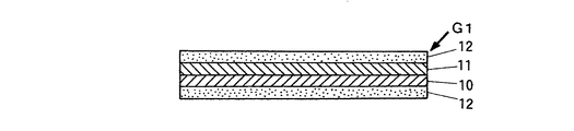
本発明で使用される第一疑似接着シートとしては、例えば図2に示すように、比較的腰のある安定したポリエチレンテレフタレート、ポリプロピレン、ポリカーボネート、アセテート等からなる樹脂層を支持体10として、その一方の面にそれよりも軟化溶融温度の低いポリエチレン、EVA、EEA、EAA、アイオノマ一等からなる熱可塑性樹脂層11(熱硬化性樹脂層でも差し支えない)を剥離可能に形成し、さらにその両外側に感熱接着剤層12を形成してなる4層構成の積層シートを好適に使用することができる。しかし、前記第一疑似接着シートの層構成や各層の材質等に特別な制限はなく、また前記特許文献1に示すように意図的に裂断が可能な材質を選択する必要がなく、極めて安価な材質の中から選択することも可能である。
As the first pseudo-adhesive sheet used in the present invention, for example, as shown in FIG. 2, a resin layer composed of relatively stable and stable polyethylene terephthalate, polypropylene, polycarbonate, acetate, etc. is used as the
また、本発明で使用される第二疑似接着シートとしては、例えば図12に示すように、比較的腰のある安定したポリエチレンテレフタレート、ポリプロピレン等からなる樹脂層を支持体130として、その一方の面に感熱接着剤層131を形成し、他方の面に疑似接着樹脂層である表面処理層132を形成してなる積層シートを好適に使用することできるが、前記構成のものに限られるものではない。なお、前記第二疑似接着シートは、ラミネート時の加熱により、透明化されるものであってもよい。 Further, as the second pseudo-adhesive sheet used in the present invention, for example, as shown in FIG. 12, a resin layer made of a relatively firm and stable polyethylene terephthalate, polypropylene or the like is used as a support 130, and one surface thereof. It is possible to suitably use a laminated sheet in which the heat-sensitive adhesive layer 131 is formed on the surface and the surface treatment layer 132 which is a pseudo-adhesive resin layer is formed on the other surface, but it is not limited to the one having the above-described configuration. . The second pseudo adhesive sheet may be made transparent by heating during lamination.
本発明における破断用ミシン目加工の手段としては、枚葉状情報通信体用紙を用いるオフセット印刷等の枚葉システムによる前記裂断可能な情報通信体の製造方法では、例えば、破断用ミシン刃、好ましくはマイクロミシン刃を具備した抜き型、特にトムソン刃型やピナクルダイ(「ピナクル」:株式会社塚谷刃物製作所の登録商標)等の腐食刃型等を好適に使用することができ、また長尺状情報通信体用紙や長尺状態に連結される枚葉状情報通信体用紙を用いるビジネスフォームシステムによる前記裂断可能な情報通信体の製造方法では、例えば通常使用される厚さ1mm未満の横刃や丸刃等に破断用ミシン刃、好ましくはマイクロミシン刃を具備させたものを好適に使用することができる。 In the present invention, the breaking perforation processing means is, for example, a breaking perforation blade, preferably in a method for producing a tearable information communication body by a sheet system such as offset printing using a sheet-like information communication body paper. Can be suitably used a punching die having a micro-sewing blade, in particular, a corrosive cutting die such as a Thomson blade die or Pinnacle die ("Pinacle": registered trademark of Tsukaya Cutlery Co., Ltd.), etc. In the manufacturing method of the tearable information communication body by the business form system using the information communication body paper or the sheet-like information communication body paper connected in a long state, for example, a commonly used horizontal blade having a thickness of less than 1 mm, A round blade or the like provided with a breaking sewing blade, preferably a micro sewing blade, can be suitably used.
前記マイクロミシン目におけるカットとアンカットの比率に制限はなく、要は、情報通信体の製造工程において、長尺状情報通信体用紙や枚葉状情報通信体用紙における単位用紙の所要辺で、葉片と第一疑似接着シート又は第二疑似接着シートを合わせて破断分離することを可能にし、且つ得られた情報通信体の廃棄時には、破断用ミシン目からの破断により断裁された辺における多数の切れ目を含む凹凸状態を呈する端面から、葉片と第一疑似接着シート又は第二疑似接着シートを合わせて裂断することを可能にする程度のミシン目であればよい。そのようなミシン目としては、本発明者等の実験によれば、カット長さ0.2mm〜0.85mm、アンカット長さ0.1mm〜0.25mmの比率を有するマイクロミシン目を好適に選択することができ、そのような組み合わせの比率の中でも、例えばカット長さ0.5mm:アンカット長さ0.15mm、カット長さ0.25mm:アンカット長さ0.15mm、或いはカット長さ0.35mm:アンカット長さ0.1mm等の比率を好適に採用してもよい。 There is no restriction on the ratio of cut and uncut at the micro perforation, and the important point is that the leaf piece is the required side of the unit paper in the long information communication body paper or the sheet information communication body paper in the manufacturing process of the information communication body. And the first pseudo-adhesive sheet or the second pseudo-adhesive sheet can be broken and separated, and at the time of disposal of the obtained information communication body, a number of cuts at the side cut by the break from the breaking perforation Any perforation that allows the leaf piece and the first pseudo-adhesive sheet or the second pseudo-adhesive sheet to be combined and torn from the end face exhibiting the concavo-convex state. As such a perforation, according to experiments by the present inventors, a micro perforation having a ratio of a cut length of 0.2 mm to 0.85 mm and an uncut length of 0.1 mm to 0.25 mm is preferable. Among the ratios of such combinations, for example, cut length 0.5 mm: uncut length 0.15 mm, cut length 0.25 mm: uncut length 0.15 mm, or cut length A ratio such as 0.35 mm: uncut length of 0.1 mm may be suitably employed.
なお、本発明における破断用ミシン目として、前記マイクロミシン目のみならず、例えばカット長さ3mm:アンカット長さ1mmやカット長さ2mm:アンカット長さ0.5mm等の比率を有する通常の切り取り用ミシン目や折り用ミシン目等を用いることも可能である。 The break perforation in the present invention is not limited to the above-mentioned micro perforation, but has a ratio of, for example, a cut length of 3 mm: an uncut length of 1 mm or a cut length of 2 mm: an uncut length of 0.5 mm. It is also possible to use a cut perforation or a folding perforation.
なお、前記破断用ミシン目の形状にも制限はなく、カット部分が例えば通常どおりの直線状や曲線状のスリットで形成されていてもよく、またカット部分として円形やその他の形状の微細な穴が連続的に形成されてミシン目とされていても差し支えない。 The shape of the breaking perforation is not limited, and the cut portion may be formed by, for example, a normal straight or curved slit, and the cut portion may be a circular or other fine hole. May be formed continuously and perforated.
即ち、破断用ミシン目におけるカットとアンカットの比率、破断用ミシン目の形状や形成手段等は、情報通信体に使用される用紙の斤量や種類、及び第一疑似接着シート、第二疑似接着シートの厚みや硬度等に応じて任意に選択すればよいのである。 That is, the ratio of cut to uncut in the breaking perforation, the shape and forming means of the breaking perforation, the amount and type of paper used for the information communication body, the first pseudo-adhesive sheet, the second pseudo-adhesive What is necessary is just to select arbitrarily according to the thickness, hardness, etc. of a sheet | seat.
上述したように、請求項1〜5に係る裂断可能な情報通信体の発明によれば、情報通信体を構成する用紙の対向葉片間に介装させる疑似接着積層体の構成材料として、従来のように高価で本来容易に裂断し得る特殊フィルムを使用することなく、たとえ安価で腰が強く、容易に裂断しないような通常のフィルム材料を基材に含む第一疑似接着シートや第二疑似接着シートを使用しても、情報通信体をその廃棄時に、破断用ミシン目からの破断により断裁された辺における、多数の切れ目を含む凹凸状態を呈する端面から引き裂くことにより、該破断面における細かい切れ目をきっかけとして裂け目が連続的に拡大し、極めて容易に裂断させることが可能である。また、本発明によれば、疑似接着積層体の構成材料として、既述のように高価で裂断し易い特殊フィルムではなく、安価で腰が強く、容易に裂断しないような通常のフィルム材料を基材に使用することが可能であることから、製品コストを著しく低下させることが可能である。
As described above, according to the invention of the tearable information communication body according to
また、請求項6〜18に係る裂断可能な情報通信体の製造方法の発明によれば、用紙の対向葉片間に介装させる疑似接着積層体の構成材料として、従来のように高価で本来容易に裂断し得る特殊フィルムではなく、安価で腰が強く、容易に裂断しないような通常のフィルム材料を基材に含む第一疑似接着シートや第二疑似接着シートを使用しても、廃棄時に極めて容易に裂断することが可能な情報通信体を製造することができる。また、本発明によれば、疑似接着積層体の構成材料として、前記のように高価で裂断し易い特殊フィルムではなく、安価で腰が強く、容易に裂断しないような通常のフィルム材料を基材に含む第一疑似接着シートや第二疑似接着シートを使用することが可能であることから、製造作業中に前記フィルムが誤って裂断を起こしたり、そのように裂断したフィルムがローラ類等に巻き付いたりするトラブルが回避され、生産効率及び製品の歩留まりが向上するものである。
Further, according to the invention of the method for manufacturing a tearable information communication body according to
請求項16に係る裂断可能な情報通信体の製造方法の発明のように、前記ラミネート工程と前記折り畳み工程の間に折り用ミシン目加工の工程が介設されている場合は、第二疑似接着シートが連続的にラミネートされた長尺状情報通信体用紙や枚葉状情報通信体用紙に、葉片と第二疑似接着シートを合わせて折り用ミシン目加工が施されるので、ラミネート工程の前に予め葉片のみに折り用ミシン目加工が施されている場合に比べて、折り畳み工程における折り畳みがより効果的且つ正確に行われることになる。 As in the invention of the tearable information communication body manufacturing method according to claim 16, when a folding perforation process is interposed between the laminating process and the folding process, Before the laminating process, a long perforated information communication sheet or a sheet-shaped information communication body sheet that has been continuously laminated is subjected to perforation for folding by combining the leaf pieces and the second pseudo adhesive sheet. Compared with the case where the perforation for folding is applied only to the leaf pieces in advance, folding in the folding process is performed more effectively and accurately.
なお、請求項17〜18に係る裂断可能な情報通信体の製造方法の発明のように、前記破断用ミシン目がマイクロミシン目、特にカット長さ0.2mm〜0.85mm、アンカット長さ0.1mm〜0.25mmの比率を有するマイクロミシン目である場合は、破断用ミシン目からの破断により断裁された辺における多数の切れ目を含む凹凸状態を呈する端面が、そのように無数の切り目を含みながら、情報通信体の製造作業中には裂断し難く、また外観及び触感共に通常の断裁刃による断裁面に極めて近い状態を呈することになる。 Note that, as in the invention of the method for manufacturing a tearable information communication body according to claims 17 to 18, the perforation for break is a micro perforation, particularly a cut length of 0.2 mm to 0.85 mm, an uncut length In the case of a micro perforation having a ratio of 0.1 mm to 0.25 mm, the end surface exhibiting a concavo-convex state including a large number of cuts on the side cut by the break from the breaking perforation is innumerable as such While including the cut, it is difficult to tear during the manufacturing operation of the information communication body, and the appearance and the touch are very close to a cutting surface by a normal cutting blade.
本発明では、情報通信体用紙における左右側及び/又は天地側の辺で破断用ミシン目からの破断により断裁され、それによって該辺の端面が多数の切れ目を含む凹凸状態に形成される。以下、本発明を実施例に基づき、図面を参照して具体的に説明する。 In the present invention, the right and left sides and / or the top and bottom sides of the information communication sheet are cut by breaking from the breaking perforations, whereby the end surfaces of the sides are formed in an uneven state including a number of cuts. Hereinafter, the present invention will be specifically described based on examples with reference to the drawings.
[長尺状二つ折り葉書用紙と第一疑似接着シートを用いた裂断可能な葉書]
図1は基本的な二つ折り葉書用紙を示すものであり、同図において、二つ折り葉書用紙S1は、第一葉片1と第二葉片2が折り線3を介して横方向に連接されて構成されている。なお、前記折り線3は、必ずしも表示されている必要はなく、折り用ミシン目等でもあってもよい。第一葉片1表面には郵便切手欄4、郵便番号欄5及び受取人の住所氏名6等が記載され、第二葉片2表面には一般情報7が記載されている。そして、第一葉片1及び第二葉片2の各裏面には個人情報8が記載されている。なお、前記個人情報8は、必ずしも秘密を要する情報である必要はなく、一般情報であっても、或いは秘密を要する個人的な情報と一般情報が混在する内容であっても差し支えない。
[A tearable postcard using a long, double-folded postcard and a first pseudo-adhesive sheet]
FIG. 1 shows a basic two-fold postcard paper. In FIG. 1, the two-fold postcard paper S1 is composed of a
前記二つ折り葉書用紙S1については、第一葉片1と第二葉片2の裏面同士が折り線3から折り畳まれて形成された対向葉片間に、図2に示す第一疑似接着シートG1が挟み込まれると共に加圧又は加圧・加熱処理を施され、図3に示す裂断可能な二つ折り葉書J1の形態に仕上げられている。前記挟み込み形式の第一疑似接着シートG1は、既述のように、比較的腰のある安定した樹脂層を支持体10として、その一方の面にそれよりも軟化溶融温度の低い熱可塑性樹脂層11を剥離可能に形成し、さらにその両外側に感熱接着剤層12を形成して構成されている。
For the two-folded postcard paper S1, the first pseudo adhesive sheet G1 shown in FIG. 2 is sandwiched between opposing leaf pieces formed by folding the back surfaces of the
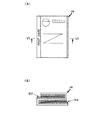
前記のように仕上げられた裂断可能な二つ折り葉書J1については、製造途中に、例えば天地側の2辺H1、H2に、葉片及び第一疑似接着シートG1を合わせてマイクロミシン刃により破断用ミシン目加工が施されると共に該辺でマイクロミシン目からの破断により断裁され、それによって、図3に示すように、前記天地側の2辺H1、H2の端面が多数の切れ目を含む凹凸状態に形成されている。 For the two-fold postcard J1 that can be torn and finished as described above, for example, the leaf piece and the first pseudo-adhesive sheet G1 are combined with the two sides H1 and H2 on the top and bottom sides for breakage with a micro-sewing blade. A perforated state in which the perforations are cut by breakage from the micro perforation at the side and the end faces of the two sides H1 and H2 on the top and bottom sides include a number of cuts as shown in FIG. Is formed.
前記のような二つ折り葉書をビジネスフォームシステムにより製造する方法では、図6に示す長尺状二つ折り葉書用紙S3と図2に示す挟み込み形式の第一疑似接着シートG1が使用される。 In the method of manufacturing the above-mentioned bi-fold postcard by the business form system, the long bi-fold postcard sheet S3 shown in FIG. 6 and the sandwiched first pseudo adhesive sheet G1 shown in FIG. 2 are used.
図6に示す長尺状二つ折り葉書用紙S3における二つ折り葉書用の単位用紙t1は、第一葉片31と第二葉片32が折り線33を介して連接されてなり、それらは切断線42を介して上下方向に連続的に連接されている。なお、前記切断線42は必ずしも表示されている必要はなく、ミシン目等であっても差し支えない。第一葉片31表面には郵便切手欄34、郵便番号欄35及び受取人の住所氏名36等が例えばプリンタ等の印字により記載されており、また第二葉片32表面には一般情報37が記載され、さらに第一葉片31及び第二葉片32の各裏面には個人情報38が各々記載されている。また、各葉片31、32の外側には、後述するピントラクタで用紙を移送するための複数のマージナル孔39が穿設されたマージナル部分40が切断線41を介して設けられている。なお、前記切断線41は必ずしも表示されている必要はなく、ミシン目等であっても差し支えない。
A unit sheet t1 for bi-fold postcards in the long bi-fold postcard sheet S3 shown in FIG. 6 is formed by connecting a
前記長尺状二つ折り葉書用紙S3は、切断線42から蛇腹状に折り畳まれており、このようなブロック単位の状態で、図7の左端下方に示す折り畳み装置の折り畳みアングル50に設置される。なお、前記長尺状二つ折り葉書用紙S3は、前記のように蛇腹状にブロック単位に折り畳まれて供給される代わりに、それらが巻き取られたロールから供給されてもよい。
The long bi-fold postcard sheet S3 is folded in a bellows shape from the cutting
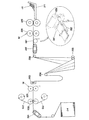
前記長尺状二つ折り葉書用紙S3は、折り線33から二つ折りに折り畳まれつつ折り畳みアングル50から上部のサポートローラ51へ引き上げられ、その後、ほぼ水平方向に進行方向を変更する。サポートローラ51を通過した前記長尺状二つ折り葉書用紙S3は、そのマージナル孔39を下流側のピントラクタ52のピンと合致させつつ、下流側のピントラクタ54に牽引されながら下流へと移送され、その途上で下方に待機したロールから連続的に繰り出される第一疑似接着シートG1が、ターンプレート53等を介して、前記長尺状二つ折り葉書用紙S3における折り畳みにより生じた対向葉片間に連続的に挿入される。
The long bi-fold postcard sheet S3 is pulled up from the
対向葉片間に第一疑似接着シートG1を挟み込んだ前記長尺状二つ折り葉書用紙S3については、先に、単位用紙t1における左右側の各辺で両外側の不要なマージナル部分40がスリッタ装置55により切り落とされ、続いて、単位用紙t1における天地側の2辺に、下流側に設置された、マイクロミシンMを装備したダイカットローラ装置56により、葉片及び第一疑似接着シートG1を合わせてマイクロミシン目加工が施されると共に該辺でマイクロミシン目からの破断により断裁され、それによって断裁された辺の端面が多数の切れ目を含む凹凸状態に形成される。断裁分離された二つ折り状態の単位用紙t1は、その対向葉片間に第一疑似接着シートG1を挟み込んだ形態で下流側のシーラ部へと移送される。
For the long half-folded postcard sheet S3 having the first pseudo adhesive sheet G1 sandwiched between the opposing leaf pieces, the unnecessary
前記シーラ部は、複数の搬送ローラ57、複数のヒータパネル58及び加圧ローラ装置59からなり、前記搬送ローラ57及びヒータパネル58は交互に且つ各々上下に対向するように配置されている。シーラ部に移送された前記二つ折り状態の単位用紙t1は、上下に対向するヒータパネル58間を加熱されながら通過する間に、対向葉片間に挟み込まれた第一疑似接着シートG1の両外側の感熱接着剤層12を前記加熱により接着性発揮状態とされ、排出口に設置された加圧ローラ装置59により加圧され、それによって対向葉片間の各対向面と第一疑似接着シートG1が接着一体化されると共に対向葉片間に第一疑似接着シートG1からなる透明な疑似接着積層体が形成される。そして、最終的に図3に示す状態に仕上げられた裂断可能な二つ折り葉書J1は、後部のベルトコンベア等からなるスタッカ60に順次積載されるのである。なお、前記シーラ部は、必要に応じて、ターンプレート53とダイカットローラ装置56の間に、即ちスリッタ装置55の前若しくは後に、又はダイカットローラ装置56の前に配置されてもよい。
The sealer section includes a plurality of
前記のようにして仕上げられた裂断可能な二つ折り葉書J1の受取人は、剥離可能に接着された対向葉片間を第一疑似接着シートG1の疑似接着部分から平面に剥離展開し、内部の個人情報38を、第一疑似接着シートG1の構成樹脂層である各透明フィルムを透して視認することができる。
The recipient of the tearable foldable postcard J1 finished as described above peels and unfolds the opposing leaf pieces, which are bonded in a peelable manner, from the pseudo-adhesive portion of the first pseudo-adhesive sheet G1 in a plane. The
前記葉書の廃棄に際して、受取人は、従来は手では引裂くことが困難であった剥離展開後の前記葉書を、前記のようにマイクロミシン目からの破断により断裁された辺における多数の切れ目を含む凹凸状態を呈する端面の任意の位置から、各葉片及び第一疑似接着シートG1の構成樹脂層を合わせて容易に引き裂くことができ、それによって安心して廃棄することができるのである。 Upon discarding the postcard, the recipient can remove the postcard after the separation and deployment, which has been difficult to tear by hand, as described above. Each leaf piece and the constituent resin layers of the first pseudo-adhesive sheet G1 can be easily torn together from any position on the end surface including the concavo-convex state, and thus can be disposed of with peace of mind.
[長尺状三つ折り葉書用紙と第一疑似接着シートを用いた裂断可能な葉書]
図4は基本的な三つ折り葉書用紙を示すものであり、同図において、三つ折り(Z折り)葉書用紙S2は、第一葉片21、第二葉片22、第三葉片23が折り線24、25を介して横方向に連接されている。第一葉片21の表面には、郵便切手欄26、郵便番号欄27及び受取人の住所氏名28等が記載され、第二葉片22及び第三葉片23の各表面には個人情報29が各々記載されている。そして、第一葉片21及び第二葉片22の各裏面には個人情報29が各々記載されており、さらに第三葉片23裏面には一般情報30が記載されている。
[A tearable postcard using a long tri-fold postcard and a first pseudo-adhesive sheet]
FIG. 4 shows a basic tri-fold postcard paper. In FIG. 4, a tri-fold (Z-fold) postcard paper S2 includes a
前記三つ折り葉書用紙S2については、第一葉片21と第二葉片22の裏面同士を対向させて折り線24から折り畳まれて形成され、さらに第二葉片22と第三葉片23の表面同士を対向させて折り線25から折り畳まれて形成された各対向葉片間に、図2に示す第一疑似接着シートG1が挟み込まれると共に加圧又は加圧・加熱処理を施され、図5に示す断面Z字状の裂断可能な三つ折り葉書J2の形態に仕上げられている。
The tri-fold postcard paper S2 is formed by folding the
前記のように仕上げられた裂断可能な三つ折り葉書J2については、製造途中に、例えば天地側の2辺H3、H4に、葉片及び第一疑似接着シートG1を合わせてマイクロミシン刃により破断用ミシン目加工が施されると共に該辺でマイクロミシン目からの破断により断裁され、それによって、図5に示すように、前記2辺H3、H4の端面が多数の切れ目を含む凹凸状態に形成されている。 For the tearable tri-fold postcard J2 finished as described above, for example, the leaf piece and the first pseudo-adhesive sheet G1 are aligned with the two sides H3 and H4 on the top and bottom side for breakage by a micro-sewing blade during the manufacturing process. The perforation is performed and the side is cut by breakage from the micro perforation, whereby the end surfaces of the two sides H3 and H4 are formed in an uneven state including a number of cuts as shown in FIG. ing.
前記のような三つ折り葉書をビジネスフォームシステムにより製造する方法では、図8に示す長尺状三つ折り葉書用紙S4と図2に示す挟み込み形式の第一疑似接着シートG1が使用される。 In the method of manufacturing the tri-fold postcard as described above by the business form system, the long tri-fold postcard paper S4 shown in FIG. 8 and the sandwiched first pseudo adhesive sheet G1 shown in FIG. 2 are used.
図8に示す長尺状三つ折り(Z折り)葉書用紙S4における三つ折り葉書用の単位用紙t2は、第一葉片71、第二葉片72及び第三葉片73が折り線74、75を介して連接されてなり、それらは切断線84を介して上下方向に連続的に連接されている。第一葉片71表面には郵便切手欄76、郵便番号欄77及び受取人の住所氏名78等が例えばプリンタ等の印字により記載されており、また第二葉片72及び第三葉片73の各表面には個人情報79が各々記載され、さらに第一葉片71及び第二葉片72の各裏面には個人情報79が記載され、第三葉片73裏面には一般情報80が記載されている。また、第一葉片71及び第三葉片73の外側には、後述するピントラクタで用紙を移送するための複数のマージナル孔81が穿設されたマージナル部分82が切断線83を介して設けられている。
A unit sheet t2 for a tri-fold postcard in the long tri-fold (Z-fold) postcard sheet S4 shown in FIG. 8 includes a
図9に示すように、前記長尺状三つ折り葉書用紙S4は、切断線84から蛇腹状にブロック単位に折り畳まれて、図中、左端下方に示す折り畳み装置の折り畳みアングル90に設置される。なお、前記長尺状三つ折り葉書用紙S4は、前記のように蛇腹状にブロック単位に折り畳まれて供給される代わりに、それらが巻き取られたロールから供給されてもよい。
As shown in FIG. 9, the elongate tri-fold postcard sheet S4 is folded into a block unit in a bellows shape from the cutting
前記長尺状三つ折り葉書用紙S4は、折り線74、75から三つ折りに折り畳まれつつ折り畳みアングル90から上部のサポートローラ91へと引き上げられ、その後、ほぼ水平方向に進行方向を変更する。サポートローラ91を通過した前記長尺状三つ折り葉書用紙S4は、そのマージナル孔81を下流側のピントラクタ92と合致させつつ、下流側のピントラクタ95に牽引されながら下流へと移送され、その途上で下方に二個所に待機したロールから連続的に繰り出される各第一疑似接着シートG1が、各々ターンプレート93、94を介して、前記長尺状三つ折り葉書用紙S4における折り畳みにより生じた二個所の対向葉片間に各々連続的に挿入される。
The elongate tri-fold postcard sheet S4 is pulled up from the
なお、前記二個所の第一疑似接着シートG1のロールの内の何れかを、前記のように対向葉片間を剥離可能に接着する第一疑似接着シートではなく、例えば対向葉片間を剥離不能に接着する両面接着シートのような接着シートに代えることも可能である。この場合、使用する用紙は三つ折り葉書用紙であっても、両面接着シートが挿入された側の対向葉片間が剥離不能に接着されるため、最終的には二つ折り葉書と実質的に同じ形態のものが得られることになる。 It should be noted that any one of the rolls of the first pseudo-adhesive sheet G1 is not the first pseudo-adhesive sheet that releasably bonds the opposing leaf pieces as described above, but, for example, the opposing leaf pieces cannot be peeled off. It is also possible to replace with an adhesive sheet such as a double-sided adhesive sheet to be adhered. In this case, even if the paper to be used is a tri-fold postcard paper, the opposing leaf pieces on the side where the double-sided adhesive sheet is inserted are bonded so as not to be peeled off. Will be obtained.
各対向葉片間に第一疑似接着シートG1を挟み込んだ前記長尺状三つ折り葉書用紙S4について、先に、単位用紙t2における左右側の各辺で両外側の不要なマージナル部分82がスリッタ装置96で切り落とされ、続いて、単位用紙t2における天地側の2辺に、下流側に設置された、マイクロミシンMを装備したダイカットローラ装置97により、葉片及び第一疑似接着シートG1を合わせてマイクロミシン目加工が施されると共に該辺でマイクロミシン目からの破断により断裁され、それによって断裁された辺の端面が多数の切れ目を含む凹凸状態に形成される。断裁分離された三つ折り状態の単位用紙t2は、その各対向葉片間に第一疑似接着シートG1を挟み込んだ形態で下流側のシーラ部へと移送され、既述の二つ折り葉書の製造方法の場合と同様に搬送ローラ98、複数のヒータパネル99及び加圧ローラ装置100からなるシーラ部を経て、図5に示すように、各対向葉片間に第一疑似接着シートG1からなる透明な疑似接着積層体が形成された、裂断可能な三つ折り葉書J2に仕上げられ、スタッカ101に順次積載される。なお、前記シーラ部は、必要に応じて、ターンプレート94とダイカットローラ装置97の間に、即ちスリッタ装置96の前若しくは後に、又はダイカットローラ装置97の前に配置されてもよい。
With respect to the long trifold postcard sheet S4 in which the first pseudo adhesive sheet G1 is sandwiched between the opposing leaf pieces, unnecessary
前記のようにして仕上げられた断面Z字状の裂断可能な三つ折り葉書J2の受取人は、剥離可能に接着された対向葉片間を第一疑似接着シートG1の疑似接着部分から平面に剥離展開し、内部の個人情報79を、第一疑似接着シートG1の構成樹脂層である各透明フィルムを透して視認することができる。
The recipient of the tearable tri-fold postcard J2 having a Z-shaped cross section finished as described above peels the opposing leaf pieces that are peelably bonded from the pseudo-adhesive portion of the first pseudo-adhesive sheet G1 to the plane. The
前記葉書の廃棄に際して、受取人は、従来は手では引裂くことが困難であった剥離展開後の前記葉書を、前記のようにマイクロミシン目からの破断により断裁された辺における多数の切れ目を含む凹凸状態を呈する端面の任意の位置から、各葉片及び第一疑似接着シートG1の構成樹脂層を合わせて容易に引き裂くことができる。 Upon discarding the postcard, the recipient can remove the postcard after the separation and deployment, which has been difficult to tear by hand, as described above. Each leaf piece and the constituent resin layers of the first pseudo-adhesive sheet G1 can be easily torn together from any position on the end face that exhibits an uneven state.
前記の実施例1において、前記シーラ部は前記構成に限るものではなく、ヒートローラ等の他の手段により加熱・加圧処理を一気に行ってもよく、さらにファンヒータで加熱したり、ヒータプレス等により加圧・加熱処理を施しても差し支えない。 In the first embodiment, the sealer portion is not limited to the above-described configuration, and the heating / pressurizing process may be performed at once by other means such as a heat roller, and further heating with a fan heater, heater press, etc. There is no problem even if pressure and heat treatment are applied.
また、実施例1において、前記単位用紙t1、t2の天地側の2辺の内の1辺のみにマイクロミシン目加工を施すと共に該辺でマイクロミシン目からの破断により断裁するように変形してもよい。さらに、前記スリッタ装置55、96にもマイクロミシンMを配備して、葉片及び第一疑似接着シートG1を合わせて、単位用紙t1、t2における左右側の1〜2辺でマイクロミシン目からの破断により断裁するように構成することも可能である。前記単位用紙t1、t2の天地側の1〜2辺でのマイクロミシン目からの破断による断裁を要しない場合は、該辺を通常の断裁、例えばマイクロミシンMを装備しない通常のダイカットローラ装置やギロチン式断裁装置等による断裁に供してもよい。
Further, in the first embodiment, only one of the two sides on the top and bottom sides of the unit papers t1 and t2 is subjected to micro perforation, and the side is deformed so as to be cut by breakage from the micro perforation. Also good. Further, a micro-sewing machine M is also provided in the
[枚葉状二つ折り葉書用紙と第二疑似接着シートを用いた裂断可能な葉書]
既述のような二つ折り葉書をオフセット印刷等の枚葉システムにより製造する方法では、図10に示す枚葉状二つ折り葉書用紙S5と図12に示すラミネート用の第二疑似接着シートG2が使用される。
[A tearable postcard using a sheet-like folded paper and a second pseudo-adhesive sheet]
In the method for manufacturing a bi-fold postcard as described above by a sheet-feed system such as offset printing, the sheet-like bi-fold postcard sheet S5 shown in FIG. 10 and the second pseudo adhesive sheet G2 for lamination shown in FIG. 12 are used. The
図10に示すように、菊四つ切サイズの枚葉状二つ折り葉書用紙S5には、二つ折り葉書用の単位用紙t3が4丁印刷されている。前記単位用紙t3は、第一葉片111と第二葉片112が折り線113を介して連接されてなり、第一葉片111表面には郵便切手欄114、郵便番号欄115及び受取人の住所氏名116等が例えばプリンタ等の印字により記載されており、また第二葉片112表面には一般情報117が記載され、さらに第一葉片葉片111及び第二葉片112の各裏面には個人情報118が各々記載されている。
As shown in FIG. 10, four unit sheets t3 for two-fold postcards are printed on the sheet-like two-fold postcard sheet S5 of the chrysanthemum quadrilateral size. The unit sheet t3 is formed by connecting a
前記枚葉状二つ折り葉書用紙S5の裏面には、図11に示すように、所要情報の印刷後に、疑似接着予定面及びその周辺を含むほぼ全面にわたって図12に示す第二疑似接着シートG2がラミネートされる。前記ラミネート用の第二疑似接着シートG2は、既述のように、比較的腰のある安定した樹脂層を支持体130として、その一方の面に感熱接着剤層131を形成し、他方の面に疑似接着樹脂層である表面処理層132を形成して構成されている。 As shown in FIG. 11, the second pseudo-adhesive sheet G2 shown in FIG. 12 is laminated on the back surface of the sheet-like folded postcard paper S5 over almost the entire surface including the pseudo-adhesive planned surface and its periphery after the required information is printed. Is done. As described above, the second pseudo-adhesive sheet G2 for laminating has a heat-sensitive adhesive layer 131 formed on one surface of a stable resin layer having a relatively low waist as a support 130, and the other surface. The surface treatment layer 132 which is a pseudo-adhesive resin layer is formed.
前記ラミネートを施した前記枚葉状二つ折り葉書用紙S5は、例えばマイクロミシン刃を具備したトムソン刃型等の抜き型により、図13に示すように、左右側及び天地側の各辺で裁断され、得られた単品の二つ折り葉書用の単位用紙t3には、裏面全面に第二疑似接着シートG2がラミネートされ、左右側及び天地側の4辺全てで、葉片及び第二疑似接着シートG2を合わせてマイクロミシン目から破断され、それによって断裁された辺の端面が多数の切れ目を含む凹凸状態に形成される。なお、必要に応じて、左右側及び天地側の4辺の内、所要の1〜3辺で、マイクロミシン目からの破断により断裁するように構成することも可能である。 The sheet-like two-folded postcard paper S5 subjected to the lamination is cut at each side of the left and right sides and the top and bottom sides, as shown in FIG. 13, by a punching die such as a Thomson blade type having a micro-sewing blade, for example. The obtained unit paper t3 for the two-fold postcard is laminated with the second pseudo adhesive sheet G2 on the entire back surface, and the leaf pieces and the second pseudo adhesive sheet G2 are combined on all four sides of the left and right sides and the top and bottom sides. Thus, the end surface of the side that is cut from the micro perforation and thereby cut is formed in an uneven state including a number of cuts. In addition, if necessary, it is also possible to configure to cut by breakage from the micro perforation at required one to three sides among the four sides on the left and right sides and the top and bottom sides.
既述のように第二疑似接着シートG2をラミネートされると共に断裁分離された二つ折り葉書用の単位用紙t3は、図15に示すシーラ機における左側の折り機120に載せられると共に折りに掛けられ、ラミネート面同士を対向させて折り線113から二つ折りに折り畳まれた状態で搬送テーブル122に排出される。搬送テーブル122に排出された前記単位用紙t3は、そのまま自動的に、既述のビジネスフォームシステムの場合と同様に、搬送ローラ123とヒータパネル124の組み合わせ工程を加熱されつつ通過すると共に加圧ローラ装置125により加圧される。前記のような折り畳み状態の単位用紙t3の加熱・加圧処理により、対向葉片間の各対向面にラミネートされていた第二疑似接着シートG2の表面処理層同士が剥離可能に接着一体化されると共に対向葉片間には第二疑似接着シートG2同士を剥離可能に接着してなる透明な疑似接着積層体が形成され、図14に示す裂断可能な二つ折り葉書J3に仕上げられてスタッカ126に順次積載されるのである。
As described above, the unit paper t3 for the two-fold postcard laminated with the second pseudo adhesive sheet G2 and cut and separated is placed on the
前記のようにして仕上げられた裂断可能な二つ折り葉書J3の受取人は、剥離可能に接着された対向葉片間を第二疑似接着シートG2同士の疑似接着部分から平面に剥離展開し、内部の個人情報118を、透明な第二疑似接着シートG2を透して視認することができる。そして、受取人は、従来は手では引裂くことが困難であった剥離展開後の前記二つ折り葉書J3を、前記のようにマイクロミシン目からの破断により断裁された辺における多数の切れ目を含む凹凸状態を呈する端面の任意の位置から、各葉片及び第二疑似接着シートG2の構成樹脂層を合わせて容易に引き裂くことができる。
The recipient of the tearable foldable postcard J3 finished as described above peels and unfolds the opposing leaf pieces, which are bonded in a peelable manner, from the pseudo-adhesive portion between the second pseudo-adhesive sheets G2 in a plane. The
[枚葉状三つ折り葉書用紙と第二疑似接着シートを用いた裂断可能な葉書]
既述のような三つ折り葉書をオフセット印刷等の枚葉システムにより製造する方法では、図16に示す枚葉状三つ折り(Z折り)葉書用紙S6と図12に示すラミネート用の第二疑似接着シートG2が使用される。
[A tearable postcard using a sheet-like tri-fold postcard and a second pseudo-adhesive sheet]
In the method of manufacturing a tri-fold postcard as described above by a sheet-feed system such as offset printing, the sheet-like tri-fold (Z-fold) postcard paper S6 shown in FIG. 16 and the second pseudo adhesive sheet for lamination shown in FIG. G2 is used.
図16に示すように、菊四つ切サイズの枚葉状三つ折り葉書用紙S6には、3葉片が横方向に連接されてなる三つ折り葉書用の単位用紙t4が3丁面付けされている。 As shown in FIG. 16, three sheets of unit paper t4 for tri-fold postcards in which three leaf pieces are connected in the horizontal direction are imprinted on the sheet-like tri-fold postcard sheet S6 of chrysanthemum quadrilateral size.
前記の枚葉状三つ折り葉書用紙S6についても、既述の枚葉状二つ折り葉書用紙S5の場合と同様に、表裏面における疑似接着予定面に第二疑似接着シートG2によるラミネートが施されると共にマイクロミシン刃により左右側及び天地側の各辺で単品の三つ折り葉書用の単位用紙t4に裁断され、最終的に図17(A)に示すように断面Z字状の裂断可能な三つ折り葉書となり、左右側及び天地側の4辺全てで、葉片及び第二疑似接着シートG2を合わせてマイクロミシン目から破断された形態とされている。なお、必要に応じて、左右側及び天地側の4辺の内、所要の1〜3辺で、マイクロミシン目からの破断により断裁するように構成してもよい。また、第二疑似接着シートG2による前記ラミネートは、必要に応じて、前記枚葉状三つ折り葉書用紙S6における剥離可能な疑似接着に供される葉片の疑似接着予定面のみならず、剥離可能な疑似接着に供されずに折り畳み後に表出する葉片にも拡張して施されてもよい。 The sheet-like tri-folded postcard sheet S6 is also laminated with the second pseudo-adhesive sheet G2 on the pseudo-adhesive planned surfaces on the front and back surfaces as in the case of the sheet-like two-folded postcard sheet S5 described above. A tri-fold postcard that is cut into unit paper t4 for a single tri-fold postcard on each of the left and right sides and the top and bottom sides by a sewing blade, and finally can be torn as shown in FIG. Thus, the leaf piece and the second pseudo-adhesive sheet G2 are combined and broken from the micro perforation along all four sides on the left and right sides and the top and bottom sides. In addition, as needed, you may comprise so that it cuts by the fracture | rupture from a micro perforation in required 1-3 sides among 4 sides of the right-and-left side and the top-and-bottom side. In addition, the laminate by the second pseudo-adhesive sheet G2 can be peeled off as well as the pseudo-adhesive planned surface of the leaf pieces used for the peelable pseudo-adhesion in the sheet-like tri-folded postcard paper S6 as necessary. You may extend and apply to the leaf piece exposed after folding, without using for adhesion | attachment.
また、前記の断面Z字状の裂断可能な三つ折り葉書について折り畳み態様及び疑似接着予定面を変更し、図17(B)に示すように巻き折り形態の裂断可能な三つ折り葉書とすることも可能である。さらに、前記三つ折り葉書について折り畳み態様及び疑似接着予定面を変更し、図17(C)に示すように、二つ折り葉書に返信葉書が連接された形態の裂断可能な往復葉書とすることも可能である。前記ような形態の葉書においても、左右側及び天地側の4辺全て又はその内の所要の1〜3辺で、マイクロミシン目から破断された形態とされる。 In addition, the folding mode and the pseudo-adhesive planned surface of the tri-fold postcard having a Z-shaped cross section can be changed to form a tri-fold postcard in the form of winding as shown in FIG. It is also possible. Further, the folding mode and the pseudo-adhesive planned surface of the tri-folded postcard are changed, and as shown in FIG. 17C, a reciprocating postcard in which a reply postcard is connected to the two-folded postcard may be used. Is possible. Also in the postcard of the above-mentioned form, it is a form that is broken from the micro perforation on all four sides on the left and right sides and the top and bottom sides or on the required 1-3 sides thereof.
[長尺状三つ折り葉書用紙と第二疑似接着シートを用いた裂断可能な葉書]
既述のような三つ折り葉書をビジネスフォームシステムにより製造する別の方法では、図8に示す長尺状三つ折り(Z折り)葉書用紙S4と図12に示すラミネート用の第二疑似接着シートG2が使用される。
[A tearable postcard using a long tri-fold postcard and a second pseudo-adhesive sheet]
In another method of manufacturing a tri-fold postcard as described above by the business form system, the long tri-fold (Z-fold) postcard paper S4 shown in FIG. 8 and the second pseudo adhesive sheet G2 for lamination shown in FIG. Is used.
図19に示すように、前記長尺状三つ折り葉書用紙S4は、例えば切断線84から蛇腹状にブロック単位に折り畳まれて図中、左側下方に配置され、そこから上方のピントラクタ201を介して下流へと移送されるのであるが、その途上で、上方及び下方に待機したロールからラミネートローラ202を介して連続的に繰り出される第二疑似接着シートG2が、図18及び図20(A)に示すように、前記長尺状三つ折り葉書用紙S4の第二葉片72及び第三葉片73の両表面並びに第一葉片71及び第二葉片72の両裏面の疑似接着予定面にスポット的にラミネートされる。
As shown in FIG. 19, the elongate tri-fold postcard sheet S4 is folded, for example, in a bellows shape from the cutting
なお、前記長尺状三つ折り葉書用紙S4は、前記のように蛇腹状にブロック単位に折り畳まれて供給される代わりに、それらが巻き取られたロールから供給されてもよい。また、第二疑似接着シートG2による前記ラミネートは、必要に応じて、前記長尺状三つ折り葉書用紙S4における剥離可能な疑似接着に供される葉片の疑似接着予定面のみならず、剥離可能な疑似接着に供されずに折り畳み後に表出する葉片、例えば第一葉片71の表面及び/又は第三葉片73の裏面にも拡張して施されてもよい。
In addition, the elongate tri-fold postcard sheet S4 may be supplied from a roll around which the elongate tri-fold postcard sheet S4 is wound instead of being supplied in a accordion shape in units of blocks. In addition, the laminate by the second pseudo-adhesive sheet G2 can be peeled off not only as the pseudo-adhesive planned surface of the leaf piece used for the peelable pseudo-adhesion in the long tri-fold postcard paper S4, if necessary. It may be applied to a leaf piece that is not subjected to pseudo-adhesion and is exposed after folding, for example, the front surface of the
ラミネートが施された前記長尺状三つ折り葉書用紙S4は、ニップローラ203により排出され、サポートローラ204との間に弛みを形成した後に、続く下流の折り畳みアングル205からサポートローラ206に到達する間に、図20(B)に示すように、ラミネート面同士を対向させて折り線74、75から断面Z字状の三つ折り状態に折り畳まれる。
The elongated tri-fold postcard sheet S4 that has been laminated is discharged by the
断面Z字状に折り畳まれた前記長尺状三つ折り葉書用紙S4は、サポートローラ206を介して水平方向に進行し、そのマージナル孔81を下流側のピントラクタ207と合致させながら下流へ搬送され、単位用紙t2における左右側の各辺で両外側のマージナル部分82がスリッタ装置208により切り落とされ、続いて、単位用紙t2における天地側の2辺に、マイクロミシンMを装備したダイカットローラ装置209により、葉片及び第二疑似接着シートG2を合わせてマイクロミシン目加工が施されると共に該辺でマイクロミシン目からの破断により断裁され、それによって断裁された辺の端面が多数の切れ目を含む凹凸状態に形成される。断裁分離された三つ折り状態の単位用紙t2は、その各対向葉片間の対向面に第二疑似接着シートG2がラミネートされた形態で下流に移送され、ヒートローラ装置210を通過して加圧或いは加圧・加熱処理を施されると共にそれによって対向する第二疑似接着シートG2の表面処理層同士が剥離可能に接着一体化され、図21(A)及び(B)に示す断面Z字状の裂断可能な三つ折り葉書J4に仕上げられて、後部のベルトコンベア等からなるスタッカ211に順次積載される。なお、前記ヒートローラ装置210は、必要に応じて、サポートローラ206とダイカットローラ装置209の間に、即ちスリッタ装置208の前若しくは後に、又はダイカットローラ装置209の前に配置されてもよい。
The long tri-fold postcard sheet S4 folded in a Z-shaped cross section proceeds in the horizontal direction via the
なお、前記のようにダイカットローラ装置209にマイクロミシンMを配備する代わりに、又はそれと共に、スリッタ装置208又はそれに代わる左右側断裁装置にマイクロミシンMを配備して、葉片及び第二疑似接着シートG2を合わせて、単位用紙t2における左右側の1〜2辺でマイクロミシン目からの破断により断裁するように構成することも可能である。
In addition to or instead of arranging the micro-sewing machine M in the die-
例えば、図22(A)及び(B)に示す裂断可能な三つ折り葉書J4は、何れもマイクロミシンMを配備したダイカットローラ装置209及びスリッタ装置208又はそれに代わる左右側断裁装置により、左右側の2辺及び天地側の2辺の全ての辺でマイクロミシン目からの破断により断裁された状態の単位用紙t2から得られたものである。
For example, the tearable tri-fold postcard J4 shown in FIGS. 22 (A) and 22 (B) is obtained by the die cut
また、図23(A)及び(B)に示す裂断可能な三つ折り葉書J4は、前記と略同様にして、左右側の1辺(左辺)及び天地側の2辺でマイクロミシン目からの破断により断裁された状態の単位用紙t2から得られたものである。この例では、図8に示す長尺状三つ折り葉書用紙S4の代わりに、第一葉片71を第二葉片72及び第三葉片73のよりも若干幅狭く形成すると共に第二葉片72裏面における折り線75に隣接する端縁に「POST CARD」の文字を印刷してなる長尺状三つ折り葉書用紙が使用され、得られた三つ折り葉書J4には、第一葉片71におけるマイクロミシン目からの破断により断裁された辺に隣接して、第二葉片72における「POST CARD」の文字が印刷された裏面が帯状に表出している。
In addition, the tearable tri-fold postcard J4 shown in FIGS. 23 (A) and 23 (B) is substantially the same as described above, and is separated from the micro perforation by one side on the left and right sides (left side) and two sides on the top and bottom sides. This is obtained from the unit paper t2 that has been cut by breaking. In this example, the
さらに、図24(A)及び(B)に示す裂断可能な三つ折り葉書J4は、図23(A)及び(B)に示す前記三つ折り葉書J4において、左右側の他辺(右辺)でも、図22(A)及び(B)に示す前記三つ折り葉書J4における左右側の右辺と同様の形態で、マイクロミシン目からの破断により断裁されたものである。 Further, the tearable tri-fold postcard J4 shown in FIGS. 24 (A) and 24 (B) is the same as the tri-fold postcard J4 shown in FIGS. 23 (A) and 23 (B). FIGS. 22A and 22B are cut in the same manner as the right side of the left and right sides of the tri-fold postcard J4 shown in FIG.
なお、図23(A)及び(B)や図24(A)及び(B)に示す前記裂断可能な三つ折り葉書J4においては、前記のように、他の2葉片より若干幅狭く形成された第一葉片71におけるマイクロミシン目からの破断により断裁された辺が、第二葉片72における折り線75に隣接する端縁から内側に入り込んでいるので、これらの三つ折り葉書J4の製造に際して、左右側の前記辺(左辺)は、断面Z字状の三つ折り状態に折り畳まれる前にマイクロミシン目加工及び該マイクロミシン目からの破断による断裁に供される必要があり、そのような工程は、後述する図26〜29に示す各製造方法において適宜実施することができる。
In the tri-foldable postcard J4 shown in FIGS. 23A and 23B and FIGS. 24A and 24B, as described above, it is formed slightly narrower than the other two-leaf pieces. Since the side cut by the break from the micro perforation in the
前記のようにして仕上げられた断面Z字状の裂断可能な三つ折り葉書J4の受取人は、剥離可能に接着された対向葉片間を第二疑似接着シートG2同士の疑似接着部分から平面に剥離展開し、内部の個人情報79を、透明な第二疑似接着シートG2を透して視認することができる。そして、前記葉書の廃棄に際して、受取人は、従来は手では引裂くことが困難であった剥離展開後の前記三つ折り葉書J4を、前記のようにマイクロミシン目からの破断により断裁された辺における多数の切れ目を含む凹凸状態を呈する端面の任意の位置から、各葉片及び第二疑似接着シートG2の構成樹脂層を合わせて容易に引き裂くことができる。
The recipient of the tearable tri-fold postcard J4 having a Z-shaped cross section finished as described above makes the plane between the pseudo-adhesive portions between the second pseudo-adhesive sheets G2 between the opposing leaf pieces that are peelably bonded. By peeling and developing, the internal
図19に示す前記裂断可能な情報通信体の製造方法において、ラミネート工程と折り畳み工程の間に、長尺状情報通信体用紙や連続的に供給される枚葉状情報通信体用紙に、葉片と第二疑似接着シートを合わせて折り用ミシン目加工を施すために、図25に示すように、ラミネートローラ202とニップローラ203の間に折り用ミシン丸刃装置221が介設されてもよい。
In the method for manufacturing the tearable information communication body shown in FIG. 19, between the laminating step and the folding step, the long information communication body paper or the continuously fed sheet information communication body paper, In order to perform the perforation processing for folding together with the second pseudo adhesive sheet, a folding sewing machine
また、図19に示す前記裂断可能な情報通信体及びその製造方法において、ラミネートが施された前記長尺状三つ折り葉書用紙S4における単位用紙t2の左右側の1〜2辺へのマイクロミシン目加工及び該辺でのマイクロミシン目からの破断による断裁が、ラミネート工程と折り畳み工程との間で行われるように変形することもできる。 Further, in the tearable information communication body and the manufacturing method thereof shown in FIG. 19, the micro-sewing machine on the left and right sides of the unit paper t2 in the elongated tri-fold postcard paper S4 to which the laminate is applied. It can also be modified such that the cutting by the break from the micro perforation at the side and the side is performed between the laminating step and the folding step.
図26に示す第一変形態様では、ラミネートローラ202とニップローラ203の間に、マイクロミシンMを装備した丸刃装置231が設けられ、既述のようにラミネートローラ202を通過してラミネートされた前記長尺状三つ折り葉書用紙S4における単位用紙t2の左右側の1辺に、前記丸刃装置231により、葉片及び第二疑似接着シートG2を合わせてマイクロミシン目加工が施されると共に該辺で一方側のマージナル部分82がマイクロミシン目からの破断により断裁され、それによって断裁された辺の端面が多数の切れ目を含む凹凸状態に形成される。
In the first modification shown in FIG. 26, a
その後、前記長尺状三つ折り葉書用紙S4は、既述の工程どおり、ニップローラ203を経て折り畳みアングル205により折り畳まれ、他方側のマージナル部分82のマージナル孔81を下流側のピントラクタ207と合致させながら下流に移送され、スリッタ装置208により、左右側の他方の辺で他方側の残りのマージナル部分82が断裁され、続いて、既述の工程どおり、単位用紙t2の天地側の2辺に、マイクロミシンMを装備したダイカットローラ装置209により、葉片及び第二疑似接着シートG2を合わせてマイクロミシン目加工が施されると共に該辺でマイクロミシン目からの破断により断裁され、それによって断裁された辺の端面が多数の切れ目を含む凹凸状態に形成される。断裁分離された三つ折り状態の単位用紙t2は、その各対向葉片間の対向面に第二疑似接着シートG2がラミネートされた形態で下流に移送され、ヒートローラ装置210を通過して加圧或いは加圧・加熱処理を施されると共にそれによって対向する第二疑似接着シートG2の表面処理層同士が剥離可能に接着一体化される。なお、前記ヒートローラ装置210は、必要に応じて、サポートローラ206とダイカットローラ装置209の間に、即ちスリッタ装置208の前若しくは後に、又はダイカットローラ装置209の前に配置されてもよい。
Thereafter, the long tri-fold postcard sheet S4 is folded by the
図27に示す第二変形態様では、図26に示す第一変形態様がさらに変形され、既述のようにラミネートローラ202を通過してラミネートされた前記長尺状三つ折り葉書用紙S4における単位用紙t2の左右側の2辺に、前記丸刃装置231により、葉片及び第二疑似接着シートG2を合わせてマイクロミシン目加工が施されると共に前記2辺のうちの1辺で一方側のマージナル部分82がマイクロミシン目からの破断により断裁され、それによって断裁された辺の端面が多数の切れ目を含む凹凸状態に形成される。
In the second modification shown in FIG. 27, the first modification shown in FIG. 26 is further modified, and the unit sheet in the long tri-fold postcard sheet S4 laminated through the
その後、前記長尺状三つ折り葉書用紙S4は、既述の工程どおり、ニップローラ203を経て折り畳みアングル205により折り畳まれ、他方側のマージナル部分82のマージナル孔81を下流側のピントラクタ207と合致させながら下流に移送され、既述のスリッタ装置208に代わる破断用ローラ241により、左右側の他方の辺で他方側の残りのマージナル部分82が断裁され、それによって断裁された辺の端面が多数の切れ目を含む凹凸状態に形成される。続いて、既述の工程どおり、単位用紙t2の天地側の2辺に、マイクロミシンMを装備したダイカットローラ装置209により、葉片及び第二疑似接着シートG2を合わせてマイクロミシン目加工が施されると共に該辺でマイクロミシン目からの破断により断裁され、それによって断裁された辺の端面が多数の切れ目を含む凹凸状態に形成される。断裁分離された三つ折り状態の単位用紙t2は、その各対向葉片間の対向面に第二疑似接着シートG2がラミネートされた形態で下流に移送され、ヒートローラ装置210を通過して加圧或いは加圧・加熱処理を施されると共にそれによって対向する第二疑似接着シートG2の表面処理層同士が剥離可能に接着一体化される。なお、前記ヒートローラ装置210は、必要に応じて、サポートローラ206とダイカットローラ装置209の間に、即ち破断用ローラ241の前若しくは後に、又はダイカットローラ装置209の前に配置されてもよい。
Thereafter, the long tri-fold postcard sheet S4 is folded by the
図28に示す第三変形態様では、図26に示す第一変形態様がさらに別形態に変形され、既述のようにラミネートローラ202を通過してラミネートされた前記長尺状三つ折り葉書用紙S4における単位用紙t2の左右側の1辺に、前記丸刃装置231により、葉片及び第二疑似接着シートG2を合わせてマイクロミシン目加工が施されると共に該辺で一方側のマージナル部分82がマイクロミシン目からの破断により断裁され、それによって断裁された辺の端面が多数の切れ目を含む凹凸状態に形成される。
In the third modified embodiment shown in FIG. 28, the first modified embodiment shown in FIG. 26 is further transformed into another form, and the long tri-fold postcard paper S4 laminated through the
その後、前記長尺状三つ折り葉書用紙S4は、既述の工程どおり、ニップローラ203を経て折り畳みアングル205により折り畳まれ、他方側のマージナル部分82のマージナル孔81を下流側のピントラクタ207と合致させながら下流に移送され、左右側の他方の辺に、既述のスリッタ装置208に代わるマイクロミシンMを装備した丸刃装置251により、葉片及び第二疑似接着シートG2を合わせてマイクロミシン目加工が施されると共に該辺で他方側のマージナル部分82がマイクロミシン目からの破断により断裁され、それによって断裁された辺の端面が多数の切れ目を含む凹凸状態に形成される。続いて、既述の工程どおり、単位用紙t2の天地側の2辺に、マイクロミシンMを装備したダイカットローラ装置209により、葉片及び第二疑似接着シートG2を合わせてマイクロミシン目加工が施されると共に該辺でマイクロミシン目からの破断により断裁され、それによって断裁された辺の端面が多数の切れ目を含む凹凸状態に形成される。断裁分離された三つ折り状態の単位用紙t2は、その各対向葉片間の対向面に第二疑似接着シートG2がラミネートされた形態で下流に移送され、ヒートローラ装置210を通過して加圧或いは加圧・加熱処理を施されると共にそれによって対向する第二疑似接着シートG2の表面処理層同士が剥離可能に接着一体化される。なお、前記ヒートローラ装置210は、必要に応じて、サポートローラ206とダイカットローラ装置209の間に、即ち丸刃装置251の前若しくは後に、又はダイカットローラ装置209の前に配置されてもよい。
Thereafter, the long tri-fold postcard sheet S4 is folded by the
前記の実施例3の第一〜第三変形態様においても、図25に示すように、ラミネートローラ202とニップローラ203の間に折り用ミシン丸刃装置221が、必要に応じて丸刃装置231と同軸上に介設されてもよい。また、前記の実施例3において、前記単位用紙t2の天地側の2辺の内の1辺のみにマイクロミシン目加工を施すと共に該辺でマイクロミシン目からの破断により断裁するように変形してもよい。天地側の1〜2辺でのマイクロミシン目からの破断による断裁を要しない場合は、該辺を通常の断裁、例えばマイクロミシンMを装備しない通常のダイカットローラ装置やギロチン式断裁装置等による断裁に供してもよい。
Also in the first to third modifications of the third embodiment, as shown in FIG. 25, the folding sewing machine
[連続的に供給される枚葉状葉書用紙と第二疑似接着シートを用いた裂断可能な葉書]
既述のような三つ折り葉書をビジネスフォームシステムにより製造する別の方法では、3葉片が折り線及び/又は切取線を介して横方向に連接されてなる、図16に示すような三つ折り葉書用の単位用紙t4が3丁面付けされた枚葉状三つ折り(Z折り)葉書用紙S6と第二疑似接着シートG2が使用され、既述の実施例3と類似の工程が配備される。
[A tearable postcard using continuously supplied sheet-fed postcard paper and a second pseudo-adhesive sheet]
In another method for producing a tri-fold postcard as described above by the business form system, the tri-leaf post is connected in the lateral direction via a fold line and / or a cut line, and is used for a tri-fold postcard as shown in FIG. A sheet-like three-fold (Z-fold) postcard sheet S6 on which three unit sheets t4 are imprinted and the second pseudo-adhesive sheet G2 are used, and a process similar to that of the above-described third embodiment is provided.
図29に示すように、図中、左側下方に積載された枚葉状三つ折り葉書用紙S6が、吸着パッド262により1枚ずつ吸い上げられて搬送台261上に送り出されると共に給紙ローラ263により下流に順次連続的に等間隔で搬送され、上方及び下方に待機したロールからラミネートローラ202を介して連続的に繰り出される第二疑似接着シートG2が、枚葉状三つ折り葉書用紙S6の表裏の疑似接着予定面にスポット的にラミネートされ、それによって、連続的に供給される枚葉状三つ折り葉書用紙S6は長尺状態に連結される。なお、第二疑似接着シートG2による前記ラミネートは、必要に応じて、前記枚葉状三つ折り葉書用紙S6における剥離可能な疑似接着に供される葉片の疑似接着予定面のみならず、剥離可能な疑似接着に供されずに折り畳み後に表出する葉片の表面や裏面にも拡張して施されてもよい。
As shown in FIG. 29, in the drawing, the sheet-like tri-fold postcard sheets S6 stacked on the lower left side are sucked up one by one by the
ラミネートが施されると共に長尺状態に連結された枚葉状三つ折り葉書用紙S6は、同軸上に配置された折り用ミシン丸刃装置221及びマイクロミシンMを装備した丸刃装置231に通され、前記枚葉状三つ折り葉書用紙S7に、折り用ミシン丸刃装置221により、葉片及び第二疑似接着シートG2を合わせて折り用ミシン目加工が施され、それと同時に該枚葉状三つ折り葉書用紙S6における単位用紙t4の左右側の2辺に、前記丸刃装置231により、葉片及び第二疑似接着シートG2を合わせてマイクロミシン目加工が施されると共に該辺でマイクロミシン目からの破断により断裁され、それによって断裁された辺の端面が多数の切れ目を含む凹凸状態に形成される。
The sheet-like three-fold postcard paper S6 that is laminated and connected in a long state is passed through a folding sewing machine
その後、前記枚葉状三つ折り葉書用紙S6は、既述の工程どおり、ニップローラ203、サポートローラ204を経て折り畳みアングル205により折り畳まれ、サポートローラ206を経てさらに搬送され、既述の工程どおり、単位用紙t4の天地側の2辺に、マイクロミシンMを装備したダイカットローラ装置209により、葉片及び第二疑似接着シートG2を合わせてマイクロミシン目加工が施されると共に該辺でマイクロミシン目からの破断により断裁され、それによって断裁された辺の端面が多数の切れ目を含む凹凸状態に形成される。前記のように、単位用紙t4の左右側及び天地側の各辺でマイクロミシン目からの破断により断裁された枚葉状三つ折り葉書用紙S6は、ヒートローラ装置210を通過して加圧或いは加圧・加熱処理を施されると共にそれによって対向する第二疑似接着シートG2の表面処理層同士が剥離可能に接着一体化され、断面Z字状の裂断可能な三つ折り葉書J4に仕上げられて後部のスタッカ211に順次積載される。なお、前記ヒートローラ装置210は、必要に応じて、サポートローラ206とダイカットローラ装置209の間に、即ちダイカットローラ装置209の前に配置されてもよい。
Thereafter, the sheet-like three-fold postcard sheet S6 is folded by the
前記の実施例4において、必要に応じて、折り用ミシン丸刃装置221の介設を省略してもよく、また単位用紙t4における左右側及び天地側の4辺の内の1〜3辺でマイクロミシン目からの破断により断裁されるように変形することもでき、さらに単位用紙t4における左右側の1〜2辺に折り畳み工程の後にマイクロミシン目加工を施すと共に該辺でマイクロミシン目からの破断により断裁するように変形することもできる。天地側の1〜2辺でのマイクロミシン目からの破断による断裁を要しない場合は、該辺を通常の断裁、例えばマイクロミシンMを装備しない通常のダイカットローラ装置やギロチン式断裁装置等による断裁に供してもよい。
In the fourth embodiment, if necessary, the folding sewing machine
S1 二つ折り葉書用紙
S2 三つ折り葉書用紙
S3 長尺状二つ折り葉書用紙
S4 長尺状三つ折り葉書用紙
S5 枚葉状二つ折り葉書用紙
S6 枚葉状三つ折り葉書用紙
G1 第一疑似接着シート
G2 第二疑似接着シート
J1 二つ折り葉書(第一疑似接着シート使用)
J2 三つ折り葉書(第一疑似接着シート使用)
J3 二つ折り葉書(第二疑似接着シート使用)
J4 三つ折り葉書(第二疑似接着シート使用)
H1、H2 天地側の辺(二つ折り葉書)
H3、H4 天地側の辺(三つ折り葉書)
t1 長尺状二つ折り葉書用紙における単位用紙
t2 長尺状三つ折り葉書用紙における単位用紙
t3 枚葉状二つ折り葉書用紙における単位用紙
t4 枚葉状三つ折り葉書用紙における単位用紙
M マイクロミシン
1、2、2312、23、31、32、71、72、73、111、112 葉片
3、24、25、33、74、75、113 折り線
41、42、83、84 切断線
4、26、34、76、114 郵便切手欄
5、27、35、77、115 郵便番号欄
6、28、36、78、116 受取人住所氏名
7、30、37、80、117 一般情報
8、29、38、79、118 個人情報
10、130 支持体
11 熱可塑性樹脂層
12、131 感熱接着剤層
132 表面処理層
39、81 マージナル孔
40、82 マージナル部分
50、90、205 折り畳みアングル
51、91、204、206 サポートローラ
52、54、92、95、201、207 ピントラクタ
53、93、94 ターンプレート
55、96,208 スリッタ装置
56、97、209 ダイカットローラ装置
58、98、124 搬送ローラ
58、99、123 ヒータプレート
59、100、125 加圧ローラ装置
60、101、126、211 スタッカ
120 折り機
122 搬送テーブル
202 ラミネートローラ
203 ニップローラ
210 ヒートローラ装置
221 折り用ミシン丸刃装置
231、251 丸刃装置
241 破断用ローラ
261 搬送台
262 吸着パッド
263 給紙ローラ
S1 Two-fold postcard paper S2 Three-fold postcard paper S3 Long two-fold postcard paper S4 Long three-fold postcard paper S5 Single-leaf two-fold postcard paper S6 Single-leaf three-fold postcard paper G1 First pseudo adhesive sheet G2 Second pseudo Adhesive sheet J1 Folded postcard (using the first pseudo adhesive sheet)
J2 Tri-fold postcard (using first pseudo adhesive sheet)
J3 Folded postcard (using second pseudo adhesive sheet)
J4 Tri-fold postcard (using second pseudo adhesive sheet)
H1, H2 Upside down (folded postcard)
H3, H4 Upside down (tri-fold postcard)
t1 Unit paper in long bi-fold postcard paper t2 Unit paper in long tri-fold postcard paper t3 Unit paper in sheet bi-fold postcard paper t4 Unit paper in sheet tri-fold postcard paper M Micro-sewing machine 1, 2, 2312 23, 31, 32, 71, 72, 73, 111, 112 Leaf piece 3, 24, 25, 33, 74, 75, 113 Folding line 41, 42, 83, 84 Cutting line 4, 26, 34, 76, 114 Postal stamp field 5, 27, 35, 77, 115 Postal code field 6, 28, 36, 78, 116 Recipient address name 7, 30, 37, 80, 117 General information 8, 29, 38, 79, 118 Personal information DESCRIPTION OF SYMBOLS 10, 130 Support body 11 Thermoplastic resin layer 12, 131 Heat-sensitive adhesive layer 132 Surface treatment layer 39, 81 Marginal hole 40, 82 Marginal part 50, 90, 205 Folding angle 51, 91, 204, 206 Support roller 52, 54, 92, 95, 201, 207 Pin tractor 53, 93, 94 Turn plate 55, 96, 208 Slitter device 56, 97, 209 Die cut roller Device 58, 98, 124 Conveying roller 58, 99, 123 Heater plate 59, 100, 125 Pressure roller device 60, 101, 126, 211 Stacker 120 Folding machine 122 Conveying table 202 Laminating roller 203 Nip roller 210 Heat roller device 221 For folding Sewing machine round blade device 231 251 Round blade device 241 Breaking roller 261 Carriage 262 Suction pad 263 Feed roller
Claims (18)
前記情報通信体用紙における左右側及び天地側の少なくとも1辺の端面が、葉片及び疑似接着積層体を含めて、該辺における破断用ミシン目からの破断により形成された多数の切れ目を含む凹凸状態を呈することを特徴とする裂断可能な情報通信体。 A resin layer between any opposing leaf pieces produced by folding and / or stacking an information communication body paper composed of a plurality of leaf pieces connected in a lateral direction via a fold line and / or a cut line from the fold line and / or the cut line. In the information communication body that is integrated so as to be peelable through a transparent pseudo-adhesive laminate that is peelably bonded to each other,
An uneven state in which the end faces of at least one side of the left and right sides and the top and bottom sides of the information communication body paper include a number of cuts formed by breaking from the breaking perforations in the sides, including leaf pieces and pseudo-adhesive laminates. A tearable information communication body characterized by presenting
折り線及び/又は切取線を介して横方向に連接された複数の葉片からなる単位用紙が縦方向に連接されてなる長尺状情報通信体用紙を連続的に供給しつつ、折り線及び/又は切取線から連続的に折り畳み及び/又は切り重ねる工程と、前記折り畳み及び/又は切り重ね工程の後に、任意の対向葉片間に、樹脂層同士が予め剥離可能に接着されてなる第一疑似接着シートをその両外側に感熱接着剤層を介して連続的に挿入する工程と、前記挿入工程の後に、各単位用紙の左右側の各辺で断裁する工程と、前記左右側の各辺での断裁工程の後に、各単位用紙の天地側の各辺で断裁する工程と、前記挿入工程と前記天地側の各辺での断裁工程の間又は前記天地側の各辺での断裁工程の後に、対向葉片間の各対向面に、加圧又は加熱・加圧により第一疑似接着シートをその両外側の感熱接着剤層により接着させる工程とからなり、それらの工程によって対向葉片間を、第一疑似接着シートからなる疑似接着積層体を介して剥離可能に一体化してなる情報通信体の製造方法において、
前記挿入工程を経た長尺状情報通信体用紙における単位用紙の左右側及び天地側の少なくとも1辺に葉片と第一疑似接着シートを合わせて破断用ミシン目加工を施すと共に該辺で破断用ミシン目からの破断により断裁し、それによって、前記破断により断裁された辺の端面が多数の切れ目を含む凹凸状態に形成されるようにしたことを特徴とする裂断可能な情報通信体の製造方法。 A method for producing a tearable information communication body according to claim 1 or 2,
While continuously supplying a long information communication body sheet in which unit sheets composed of a plurality of leaf pieces connected in the horizontal direction via fold lines and / or cut lines are connected in the vertical direction, fold lines and / or A first pseudo-adhesive sheet in which resin layers are preliminarily bonded to each other between any opposing leaf pieces after the step of folding and / or cutting continuously from the tear line and the folding and / or cutting step. A step of continuously inserting the heat-sensitive adhesive layers on both outer sides thereof, a step of cutting at each side on the left and right sides of each unit paper after the insertion step, and a step of cutting at each side on the left and right sides After the step, cutting at each side on the top and bottom sides of each unit sheet, and between the insertion step and the cutting step at each side on the top and bottom, or after the cutting step at each side on the top and bottom sides, First, pressurize or heat / pressurize each facing surface It consists of a step of adhering a similar adhesive sheet with heat-sensitive adhesive layers on both outer sides, and by these steps, the opposing leaf pieces are integrated so as to be peelable through a pseudo-adhesive laminate composed of a first pseudo-adhesive sheet. In a method for manufacturing an information communication body,
At least one side of the unit paper in the long information communication body paper that has undergone the insertion step is subjected to perforation processing for breakage by combining the leaf pieces and the first pseudo adhesive sheet on the left and right sides, and the breakage sewing machine at the side. A method for producing a tearable information communication body, characterized in that cutting is performed by breakage from the eyes, whereby end surfaces of the sides cut by the breakage are formed in an uneven state including a number of cuts. .
折り線及び/又は切取線を介して横方向に連接された複数の葉片からなる単位用紙が1丁又は複数丁配置されてなる枚葉状情報通信体用紙における各単位用紙の少なくとも片面の任意の連接した2葉片の疑似接着予定面に、表面に疑似接着樹脂層を有する第二疑似接着シートをラミネートする工程と、前記ラミネート工程の後に、各単位用紙の左右側及び天地側の各辺で断裁する工程と、前記各辺での断裁工程の後に、ラミネート面を内側にして折り線及び/又は切取線から折り畳み及び/又は切り重ねる工程と、前記折り畳み及び/又は切り重ね工程の後に、対向葉片間を、各対向面にラミネートされた両第二疑似接着シートを介して加圧又は加熱・加圧により剥離可能に接着させる工程とからなり、それらの工程によって対向葉片間を、各対向面にラミネートされた第二疑似接着シート同士の剥離可能な接着により形成された疑似接着積層体を介して剥離可能に一体化してなる情報通信体の製造方法において、
前記ラミネート工程を経た枚葉状情報通信体用紙における単位用紙の左右側及び天地側の少なくとも1辺に葉片と第二疑似接着シートを合わせて破断用ミシン目加工を施すと共に該辺で破断用ミシン目からの破断により断裁し、それによって、前記破断により断裁された辺の端面が多数の切れ目を含む凹凸状態に形成されるようにしたことを特徴とする裂断可能な情報通信体の製造方法。 A method for producing a tearable information communication body according to claim 1 or 3,
Arbitrary continuous connection of at least one side of each unit sheet in a sheet-like information communication sheet in which one or a plurality of unit sheets composed of a plurality of leaf pieces connected in the lateral direction via a fold line and / or a cut line are arranged. A step of laminating a second pseudo-adhesive sheet having a pseudo-adhesive resin layer on the surface of the two-leaf piece pseudo-adhesion surface, and a step of cutting at each side on the left and right sides and top and bottom sides of each unit sheet after the laminating step And after the cutting step at each side, the step of folding and / or cutting from the fold line and / or the cut line with the laminate surface inside, and between the opposing leaf pieces after the folding and / or cutting step, It consists of a step of adhering so as to be peelable by pressure or heating / pressurization through both second pseudo-adhesive sheets laminated on each facing surface, and between the opposing leaf pieces by those steps, In the manufacturing method of the second pseudo adhesive sheet between the peelable adhered through pseudo adhesive laminate formed by formed by peelably integrated information communication body which is laminated on the opposite surface,
In the sheet-like information communication body paper that has undergone the laminating process, a break perforation is applied to at least one side of the unit paper on the left and right sides and the top and bottom sides of the unit paper, and a break perforation is applied on the sides. A method for producing a tearable information communication body, characterized in that the end face of the side cut by the break is formed in an uneven state including a number of cuts.
折り線及び/又は切取線を介して横方向に連接された複数の葉片からなる単位用紙が縦方向に連接されてなる長尺状情報通信体用紙を連続的に供給しつつ、該長尺状情報通信体用紙における各単位用紙の少なくとも片面の連接した2葉片の疑似接着予定面に、表面に疑似接着樹脂層を有する第二疑似接着シートを連続的にラミネートする工程と、前記ラミネート工程の後に、ラミネート面を内側にして折り線及び/又は切取線から折り畳む工程と、前記折り畳み工程の前及び/又は後に、各単位用紙の左右側の各辺で断裁する工程と、前記折り畳み工程の後で且つ前記左右側の各辺での断裁工程の後に、各単位用紙の天地側の各辺で断裁する工程と、前記折り畳み工程と前記天地側の各辺での断裁工程の間又は前記天地側の各辺での断裁工程の後に、対向葉片間を、各対向面にラミネートされた両第二疑似接着シートを介して加圧又は加熱・加圧により剥離可能に接着させる工程とからなり、それらの工程によって対向葉片間を、各対向面にラミネートされた第二疑似接着シート同士の剥離可能な接着により形成された疑似接着積層体を介して剥離可能に一体化してなる情報通信体の製造方法において、
前記ラミネート工程を経た長尺状情報通信体用紙における単位用紙の左右側の少なくとも1辺に前記折り畳み工程の前及び/又は後に葉片と第二疑似接着シートを合わせて破断用ミシン目加工を施すと共に前記折り畳み工程の前及び/又は後に該辺で破断用ミシン目からの破断により断裁し、それによって、前記破断により断裁された辺の端面が多数の切れ目を含む凹凸状態に形成されるようにしたことを特徴とする裂断可能な情報通信体の製造方法。 A method for producing a tearable information communication body according to claim 1 or 3,
While continuously supplying a long information communication body paper in which unit papers composed of a plurality of leaf pieces connected in the horizontal direction via folding lines and / or cut lines are connected in the vertical direction, the long information A step of continuously laminating a second pseudo-adhesive sheet having a pseudo-adhesive resin layer on the surface thereof on the pseudo-adhesive planned surface of the two-leaf pieces connected to at least one side of each unit paper in the communication body paper, and after the laminating step, A step of folding from the fold line and / or the cut line with the laminate surface inside, a step of cutting at each side on the left and right sides of each unit sheet before and / or after the folding step, and after the folding step and After the cutting process at each side on the left-hand side, between the process of cutting at each side on the top and bottom sides of each unit sheet, and the cutting process at each side on the folding side and the top and bottom sides, or each side on the top and bottom sides Cutting process Later, between the opposing leaf pieces, it consists of a step of adhering so as to be peelable by pressurization or heating / pressurization via both second pseudo-adhesive sheets laminated on each opposing surface, and between the opposing leaf pieces by those steps, In the manufacturing method of the information communication body that is integrated so as to be peelable through the pseudo-adhesive laminate formed by the peelable adhesion between the second pseudo-adhesive sheets laminated on each facing surface,
In the long information communication body paper that has undergone the laminating process, at least one side on the left and right sides of the unit paper is subjected to perforation for breaking by combining the leaf pieces and the second pseudo adhesive sheet before and / or after the folding process. Before and / or after the folding step, the side is cut by breakage from the breaking perforation, so that the end face of the side cut by the breakage is formed in an uneven state including a number of cuts. A method for producing a tearable information communication body.
折り線及び/又は切取線を介して横方向に連接された複数の葉片からなる単位用紙が1丁又は複数丁配置されてなる枚葉状情報通信体用紙を1枚ごとに連続的に供給しつつ、該枚葉状情報通信体用紙における各単位用紙の少なくとも片面の連接した2葉片の疑似接着予定面に、表面に疑似接着樹脂層を有する第二疑似接着シートを連続的にラミネートすると共にそれによって該枚葉状情報通信体用紙を長尺状態に連結する工程と、前記ラミネート工程の後に、ラミネート面を内側にして折り線及び/又は切取線から折り畳む工程と、前記折り畳み工程の前及び/又は後に、各単位用紙の左右側の各辺で断裁する工程と、前記折り畳み工程の後で且つ前記左右側の各辺での断裁工程の後に、各単位用紙の天地側の各辺で断裁する工程と、前記折り畳み工程と前記天地側の各辺での断裁工程の間又は前記天地側の各辺での断裁工程の後に、対向葉片間を、各対向面にラミネートされた両第二疑似接着シートを介して加圧又は加熱・加圧により剥離可能に接着させる工程とからなり、それらの工程によって対向葉片間を、各対向面にラミネートされた第二疑似接着シート同士の剥離可能な接着により形成された疑似接着積層体を介して剥離可能に一体化してなる情報通信体の製造方法において、
前記ラミネート工程を経て長尺状態に連結された枚葉状情報通信体用紙における単位用紙の左右側の少なくとも1辺に前記折り畳み工程の前及び/又は後に葉片と第二疑似接着シートを合わせて破断用ミシン目加工を施すと共に前記折り畳み工程の前及び/又は後に該辺で破断用ミシン目からの破断により断裁し、それによって、前記破断により断裁された辺の端面が多数の切れ目を含む凹凸状態に形成されるようにしたことを特徴とする裂断可能な情報通信体の製造方法。 A method for producing a tearable information communication body according to claim 1 or 3,
While continuously supplying a sheet-like information communication body sheet in which one or a plurality of unit sheets composed of a plurality of leaf pieces connected in a lateral direction via a folding line and / or a cutting line are arranged, A second pseudo-adhesive sheet having a pseudo-adhesive resin layer on the surface thereof is continuously laminated on at least one side of the unit paper in the sheet-like information communication paper, which is connected to the pseudo-adhesive planned surface of the two-leaf pieces. A unit for connecting the leaf-shaped information communication body paper in a long state, a step of folding from the fold line and / or the cut line with the laminated surface inside after the laminating step, and before and / or after the folding step. Cutting on each side on the left and right sides of the sheet, cutting on each side on the top and bottom of each unit sheet after the folding step and after the cutting process on each side on the left and right sides, and the folding Between the folding process and the cutting process at each side on the top and bottom sides, or after the cutting process at each side on the top and bottom sides, between the opposing leaf pieces, via both second pseudo adhesive sheets laminated on each facing surface It consists of a process of releasably bonding by pressurization or heating / pressurization, and a pseudo formed by releasable adhesion between the second pseudo-adhesive sheets laminated on each facing surface between the opposing leaf pieces by these processes In the manufacturing method of the information communication body that is integrated so as to be peelable through the adhesive laminate,
For breakage, the leaf piece and the second pseudo-adhesive sheet are combined with at least one side on the left and right sides of the unit paper in the sheet-like information communication body paper connected in a long state through the laminating process before and / or after the folding process. A perforation process is performed, and before and / or after the folding step, the side is cut by breakage from the breaking perforation, and thereby the end surface of the side cut by the breakage has an uneven state including a number of cuts. A method for producing a tearable information communication body, characterized by being formed.
Priority Applications (1)
| Application Number | Priority Date | Filing Date | Title |
|---|---|---|---|
| JP2009047450A JP5209543B2 (en) | 2008-04-16 | 2009-02-28 | Tearable postal information communication body and method for manufacturing the same |
Applications Claiming Priority (3)
| Application Number | Priority Date | Filing Date | Title |
|---|---|---|---|
| JP2008130132 | 2008-04-16 | ||
| JP2008130132 | 2008-04-16 | ||
| JP2009047450A JP5209543B2 (en) | 2008-04-16 | 2009-02-28 | Tearable postal information communication body and method for manufacturing the same |
Publications (2)
| Publication Number | Publication Date |
|---|---|
| JP2009274436A true JP2009274436A (en) | 2009-11-26 |
| JP5209543B2 JP5209543B2 (en) | 2013-06-12 |
Family
ID=41440281
Family Applications (1)
| Application Number | Title | Priority Date | Filing Date |
|---|---|---|---|
| JP2009047450A Expired - Fee Related JP5209543B2 (en) | 2008-04-16 | 2009-02-28 | Tearable postal information communication body and method for manufacturing the same |
Country Status (1)
| Country | Link |
|---|---|
| JP (1) | JP5209543B2 (en) |
Cited By (9)
| Publication number | Priority date | Publication date | Assignee | Title |
|---|---|---|---|---|
| JP2010137535A (en) * | 2008-12-15 | 2010-06-24 | K D K Kk | Pseudo-adhesive sheet for information communication medium, and breakable information communication medium using the same |
| JP2010286806A (en) * | 2009-06-10 | 2010-12-24 | K D K Kk | Laminated printed material that can be torn |
| JP2011240696A (en) * | 2010-05-18 | 2011-12-01 | K D K Kk | Method of manufacturing information communication medium |
| JP2012056304A (en) * | 2010-09-10 | 2012-03-22 | K D K Kk | Separation means for demarcated card part, information communicator using the same, and method for manufacturing information communicator having demarcated card part |
| JP2012116009A (en) * | 2010-11-29 | 2012-06-21 | Duplo Seiko Corp | Apparatus for manufacturing press bonding postcard |
| JP2012131209A (en) * | 2010-12-18 | 2012-07-12 | K D K Kk | Double postcard, and manufacturing method for the same |
| JP2012148545A (en) * | 2011-01-15 | 2012-08-09 | K D K Kk | Double postcard and method for manufacturing the same |
| JP2013052665A (en) * | 2011-08-31 | 2013-03-21 | K D K Kk | Reciprocating postcard manufacturing method |
| JP2015107628A (en) * | 2013-12-03 | 2015-06-11 | ケイディケイ株式会社 | Slitter, and method for manufacturing an information communicator using the slitter |
Citations (8)
| Publication number | Priority date | Publication date | Assignee | Title |
|---|---|---|---|---|
| JPH0976665A (en) * | 1995-09-13 | 1997-03-25 | Deyupuro Seiko Kk | Sealed letter manufacturing apparatus |
| JPH10129157A (en) * | 1996-10-30 | 1998-05-19 | Toppan Forms Co Ltd | postcard |
| JP2000168273A (en) * | 1998-12-08 | 2000-06-20 | K D K Kk | Information communication body manufacturing method and manufacturing apparatus |
| JP2001260089A (en) * | 2000-03-13 | 2001-09-25 | Sato Corp | Punched blade structure |
| JP2002113980A (en) * | 2000-10-11 | 2002-04-16 | K D K Kk | Method for manufacturing information communicating medium |
| JP2004025891A (en) * | 2003-08-27 | 2004-01-29 | Hisago Label Kk | Card making paper |
| JP2005014296A (en) * | 2003-06-24 | 2005-01-20 | Hisago Label Kk | Laminated card making paper |
| JP2005074997A (en) * | 2003-09-02 | 2005-03-24 | K D K Kk | Paper for pressure-sensitive paper |
-
2009
- 2009-02-28 JP JP2009047450A patent/JP5209543B2/en not_active Expired - Fee Related
Patent Citations (8)
| Publication number | Priority date | Publication date | Assignee | Title |
|---|---|---|---|---|
| JPH0976665A (en) * | 1995-09-13 | 1997-03-25 | Deyupuro Seiko Kk | Sealed letter manufacturing apparatus |
| JPH10129157A (en) * | 1996-10-30 | 1998-05-19 | Toppan Forms Co Ltd | postcard |
| JP2000168273A (en) * | 1998-12-08 | 2000-06-20 | K D K Kk | Information communication body manufacturing method and manufacturing apparatus |
| JP2001260089A (en) * | 2000-03-13 | 2001-09-25 | Sato Corp | Punched blade structure |
| JP2002113980A (en) * | 2000-10-11 | 2002-04-16 | K D K Kk | Method for manufacturing information communicating medium |
| JP2005014296A (en) * | 2003-06-24 | 2005-01-20 | Hisago Label Kk | Laminated card making paper |
| JP2004025891A (en) * | 2003-08-27 | 2004-01-29 | Hisago Label Kk | Card making paper |
| JP2005074997A (en) * | 2003-09-02 | 2005-03-24 | K D K Kk | Paper for pressure-sensitive paper |
Cited By (9)
| Publication number | Priority date | Publication date | Assignee | Title |
|---|---|---|---|---|
| JP2010137535A (en) * | 2008-12-15 | 2010-06-24 | K D K Kk | Pseudo-adhesive sheet for information communication medium, and breakable information communication medium using the same |
| JP2010286806A (en) * | 2009-06-10 | 2010-12-24 | K D K Kk | Laminated printed material that can be torn |
| JP2011240696A (en) * | 2010-05-18 | 2011-12-01 | K D K Kk | Method of manufacturing information communication medium |
| JP2012056304A (en) * | 2010-09-10 | 2012-03-22 | K D K Kk | Separation means for demarcated card part, information communicator using the same, and method for manufacturing information communicator having demarcated card part |
| JP2012116009A (en) * | 2010-11-29 | 2012-06-21 | Duplo Seiko Corp | Apparatus for manufacturing press bonding postcard |
| JP2012131209A (en) * | 2010-12-18 | 2012-07-12 | K D K Kk | Double postcard, and manufacturing method for the same |
| JP2012148545A (en) * | 2011-01-15 | 2012-08-09 | K D K Kk | Double postcard and method for manufacturing the same |
| JP2013052665A (en) * | 2011-08-31 | 2013-03-21 | K D K Kk | Reciprocating postcard manufacturing method |
| JP2015107628A (en) * | 2013-12-03 | 2015-06-11 | ケイディケイ株式会社 | Slitter, and method for manufacturing an information communicator using the slitter |
Also Published As
| Publication number | Publication date |
|---|---|
| JP5209543B2 (en) | 2013-06-12 |
Similar Documents
| Publication | Publication Date | Title |
|---|---|---|
| JP5209543B2 (en) | Tearable postal information communication body and method for manufacturing the same | |
| JP5246621B2 (en) | Tearable information communication body and manufacturing method thereof | |
| JP5342926B2 (en) | Manufacturing method of information communication body | |
| JP2012240412A (en) | Folded information communication medium and method of manufacturing the same | |
| JP2016203603A (en) | Manufacturing method of information communication body | |
| JP2019111796A (en) | Cut-off opening bookbinding type postcard and method of manufacturing the same | |
| JP2013086507A (en) | Bookbinding means of information communicator, bookbinding type information communicator using the same and method for manufacturing the same | |
| JP5826505B2 (en) | Manufacturing method of information communication body resistant to water | |
| JP5880929B2 (en) | Folding bookbinding information communication body and method for manufacturing the same | |
| JP5600259B2 (en) | Method of manufacturing tearable and breakable laminated paper, method of manufacturing tearable and breakable information communication body, and tearable and breakable information communication body | |
| JP2012183814A (en) | Information communicator resistant to wetting, and method for manufacturing the same | |
| JP2012056304A (en) | Separation means for demarcated card part, information communicator using the same, and method for manufacturing information communicator having demarcated card part | |
| JP5360706B2 (en) | Pseudo-adhesive sheet for breakable information communication body and breakable information communication body using the same | |
| JP2017170872A (en) | Information communication body and manufacturing method thereof | |
| JP2011056930A (en) | Manufacturing method of double postal card | |
| JP6454921B2 (en) | Bookbinding type reciprocal postcard and its manufacturing method | |
| JP5733657B2 (en) | Reciprocating postcard and its manufacturing method | |
| JP5545044B2 (en) | Manufacturing method of information communication body | |
| JP2011031597A (en) | Method for manufacturing double postal card | |
| JP2013052665A (en) | Reciprocating postcard manufacturing method | |
| JP7457223B2 (en) | Foldable information communication body and its manufacturing method | |
| JP6979581B2 (en) | Round-trip postcards and their manufacturing methods | |
| JP6343856B2 (en) | Folded pseudo-adhesive film sheet and method for manufacturing information communication body using the same | |
| JP2018012316A (en) | Bookbinding type information communication body and manufacturing method thereof | |
| JP2007152919A (en) | Insertion means for pseudo adhesive sheet |
Legal Events
| Date | Code | Title | Description |
|---|---|---|---|
| A621 | Written request for application examination |
Free format text: JAPANESE INTERMEDIATE CODE: A621 Effective date: 20120205 |
|
| A977 | Report on retrieval |
Free format text: JAPANESE INTERMEDIATE CODE: A971007 Effective date: 20120906 |
|
| A131 | Notification of reasons for refusal |
Free format text: JAPANESE INTERMEDIATE CODE: A131 Effective date: 20121129 |
|
| A521 | Request for written amendment filed |
Free format text: JAPANESE INTERMEDIATE CODE: A523 Effective date: 20130123 |
|
| TRDD | Decision of grant or rejection written | ||
| A01 | Written decision to grant a patent or to grant a registration (utility model) |
Free format text: JAPANESE INTERMEDIATE CODE: A01 Effective date: 20130212 |
|
| A61 | First payment of annual fees (during grant procedure) |
Free format text: JAPANESE INTERMEDIATE CODE: A61 Effective date: 20130221 |
|
| FPAY | Renewal fee payment (event date is renewal date of database) |
Free format text: PAYMENT UNTIL: 20160301 Year of fee payment: 3 |
|
| R150 | Certificate of patent or registration of utility model |
Free format text: JAPANESE INTERMEDIATE CODE: R150 Ref document number: 5209543 Country of ref document: JP Free format text: JAPANESE INTERMEDIATE CODE: R150 |
|
| R250 | Receipt of annual fees |
Free format text: JAPANESE INTERMEDIATE CODE: R250 |
|
| R250 | Receipt of annual fees |
Free format text: JAPANESE INTERMEDIATE CODE: R250 |
|
| R250 | Receipt of annual fees |
Free format text: JAPANESE INTERMEDIATE CODE: R250 |
|
| R250 | Receipt of annual fees |
Free format text: JAPANESE INTERMEDIATE CODE: R250 |
|
| LAPS | Cancellation because of no payment of annual fees |