JP2009155801A - Vibration control structure - Google Patents
Vibration control structure Download PDFInfo
- Publication number
- JP2009155801A JP2009155801A JP2007331611A JP2007331611A JP2009155801A JP 2009155801 A JP2009155801 A JP 2009155801A JP 2007331611 A JP2007331611 A JP 2007331611A JP 2007331611 A JP2007331611 A JP 2007331611A JP 2009155801 A JP2009155801 A JP 2009155801A
- Authority
- JP
- Japan
- Prior art keywords
- building
- vibration
- floor
- damping
- displacement
- Prior art date
- Legal status (The legal status is an assumption and is not a legal conclusion. Google has not performed a legal analysis and makes no representation as to the accuracy of the status listed.)
- Pending
Links
Images







Landscapes
- Buildings Adapted To Withstand Abnormal External Influences (AREA)
- Vibration Prevention Devices (AREA)
Abstract
Description
本発明は、例えばマンションやオフィスビルなどの多層構造の建物に、この建物に作用した振動エネルギーを減衰させるための制振機構を設けて構成した制振構造に関する。 The present invention relates to a vibration control structure configured by providing a vibration control mechanism for attenuating vibration energy applied to a building having a multilayer structure such as an apartment building or an office building.
従来、マンションやオフィスビルなどの多層構造の建物においては、建物内に設置した制震ダンパーによって、例えば地震時に作用した地震エネルギー(振動エネルギー)を吸収して減衰させ、建物の応答を低減させるようにしている。すなわち、制震ダンパーを設置することで耐震性能を向上させ、建物を制震構造(制振構造)にしている。また、このような制震ダンパーには、鋼材等の降伏耐力やすべり材の摩擦抵抗を利用した履歴系ダンパー、粘性体の粘性抵抗を利用したオイルダンパーなどの粘性系ダンパー、粘弾性体のせん断抵抗を利用した粘弾性系ダンパーが多用されている。 Conventionally, in multi-layered buildings such as condominiums and office buildings, the seismic damper installed in the building absorbs and attenuates, for example, seismic energy (vibration energy) that acts during an earthquake to reduce the response of the building I have to. In other words, by installing a damping damper, seismic performance is improved and the building has a damping structure (damping structure). In addition, such damping dampers include hysteresis dampers that use the yield strength of steel and frictional resistance of sliding materials, viscous dampers such as oil dampers that use viscous resistance of viscous materials, and shearing of viscoelastic materials. Viscoelastic dampers using resistance are often used.
そして、一般に、この種の制震ダンパーは、地震時に生じる建物の変形に抵抗するようにブレース、壁、間柱の形状として各階(各層)の柱と梁の架構内(層間)に設置される。しかしながら、このように制震ダンパーの設置箇所を各階の架構内に限定することで、建物の階数が多くなるほど制震ダンパーの設置台数が増え、建築計画を行う上で必要十分な台数の制震ダンパーの配置に苦慮する場合が多々ある。 In general, this type of damping damper is installed in the frame (layer) of columns and beams on each floor (each layer) in the form of braces, walls, and studs so as to resist the deformation of the building that occurs during an earthquake. However, by limiting the installation locations of damping dampers to the structure on each floor in this way, the number of damping dampers increases as the number of floors in the building increases. There are many cases where it is difficult to arrange the damper.
これに対し、特許文献1の制震構造物(制振構造)では、ブレースと制震ダンパー(可変減衰装置)からなる制震機構(制振機構)を、応答最大せん断力が大きくなる下層階においては各層(各階)ごとに設置し、下層階に比べて応答最大せん断力が小さい上層階においては2層または3層以上に跨る柱梁架構ごとに設置している。これにより、少ない設置台数で、各階ごとに制震ダンパーを設置する場合と同様の応答低減効果を得ることを可能にしている。なお、制震とは制振のうち専ら地震のみを対象としたものを指している。
On the other hand, in the damping structure (damping structure) of
一方、地震時の応答を低減する手段として、いわゆるTMD(Tuned Mass Damper)と称する制震装置(制振機構)を採用する場合もある。このTMDは、錘体(重錘)と付加バネとオイルダンパーなどの付加減衰装置とを備え、錘体が往復振動する1自由度振動系として構成されている。そして、建物の1次固有周期と同調させて、建物の振動と逆方向に錘体を振動させることにより、すなわち錘体が振動することによる慣性抵抗力(慣性質量効果)を利用することによって、建物に作用した地震エネルギーを減衰させ、建物の応答を低減させることを可能にしている。
しかしながら、特許文献1の制震構造においては、ブレースに履歴系ダンパー、粘性系ダンパー、粘弾性系ダンパーを接続して制震機構が構成され、TMDのように慣性質量効果を利用して地震エネルギーを減衰させるものではないため、建物の最下層から最上層(1階から最上階)まで連続的に制震機構(制震ダンパー)を配置することが必要になる。このため、上層階において2層または3層以上に跨る柱梁架構ごとに設置するようにしても、十分な応答低減効果を得るためには、やはり多くの制震機構(制震ダンパー)を設置することが必要になってしまう。また、制震機構の設置箇所が架構内(層間)に限定されるため、やはり建築計画を行う上で、その配置に苦慮することになる。
However, in the vibration control structure of
一方、TMDにおいても、地震のような過渡応答に対して応答低減効果を確実に発揮させるためには、建物重量の数%の重量の錘体を建物の頂部近傍に設置することが必要になる。このため、TMDを屋上庭園に一体に設けた実施例があるものの、建物への荷重負荷が大きくなり、且つ大きな設置スペースを要するため、現実的には採用できない場合が多い。 On the other hand, in TMD, it is necessary to install a weight body having a weight of several percent of the building weight in the vicinity of the top of the building in order to surely exert a response reducing effect against a transient response such as an earthquake. . For this reason, although there is an embodiment in which the TMD is integrally provided in the roof garden, the load load on the building becomes large and a large installation space is required, so that it is often not practically possible to employ.
本発明は、上記事情に鑑み、多層構造の建物への制振機構の設置台数を大幅に少なくして、確実に建物全体の応答低減効果を得ることが可能な制振構造を提供することを目的とする。 In view of the above circumstances, the present invention provides a vibration suppression structure that can significantly reduce the response reduction effect of the entire building by significantly reducing the number of vibration suppression mechanisms installed in a multilayer structure building. Objective.
上記の目的を達するために、この発明は以下の手段を提供している。 In order to achieve the above object, the present invention provides the following means.
本発明の制振構造は、多層構造の建物に、該建物に作用した振動エネルギーを減衰させるための制振機構を設置してなる制振構造であって、前記制振機構が、回転慣性質量ダンパーと付加バネを直列に接続して構成され、前記建物の中間層の架構を挟んで上下に位置する上層と下層の架構に接続して、複数層に跨って設けられていることを特徴とする。 The vibration damping structure of the present invention is a vibration damping structure in which a vibration damping mechanism for attenuating vibration energy acting on the building is installed in a multi-layer structure building, wherein the vibration damping mechanism is a rotary inertia mass. It is constructed by connecting a damper and an additional spring in series, and is provided across a plurality of layers by connecting to upper and lower frames positioned above and below the intermediate layer frame of the building. To do.
この発明においては、制振機構が回転慣性質量ダンパーと付加バネを直列に接続して構成されているため、TMDと同様に回転慣性質量と付加バネからなる付加振動系の固有振動数を建物と同調させることで、回転慣性質量ダンパーの錘体の回転慣性を利用し、その慣性抵抗力によって、同調振動数における建物の応答を低減させることができる。 In the present invention, since the vibration damping mechanism is configured by connecting the rotary inertia mass damper and the additional spring in series, the natural frequency of the additional vibration system including the rotary inertia mass and the additional spring is set to the building as in the case of TMD. By tuning, the rotational inertia of the mass of the rotary inertia mass damper can be utilized, and the response of the building at the tuning frequency can be reduced by the inertial resistance.
また、この制振機構を、複数層に跨って中間層の架構を挟んで上下に位置する上層と下層の架構に接続して設けることで、例えば建物の外周部(外側)や建物内の上下に連通する吹き抜け部(床開口部)などに設置できる。このため、従来の制震ダンパーのように架構内(層間)に設置したり、従来のTMDのように建物の頂部近傍に設置するものと比較し、設置箇所の制約が少なく、建築計画を行う上でその配置を容易に決めることが可能になる。 In addition, by providing this vibration control mechanism connected to the upper and lower frames located above and below the intermediate layer frame across multiple layers, for example, the outer periphery of the building (outside) and the upper and lower layers in the building It can be installed in the atrium (floor opening) that communicates with the For this reason, there are fewer restrictions on the installation location and the construction planning is performed in the frame (interlayer) as in the conventional seismic damper, or in the vicinity of the top of the building as in the conventional TMD. The arrangement can be easily determined above.
さらに、この制振機構を、例えば建物の階高が大きく層剛性が小さい階など、特定箇所(特定した複数階の間)にのみ設置して、建物全体の応答を低減することが可能になる。このとき、制振機構を複数層に跨って設けることにより、1層だけでは層間変位が小さい場合においても、複数層全体の相対変位(層間変位を合計した比較的大きな相対変位)を制振機構に作用させることが可能になるため、大きな制振効果を発揮させることが可能になる。このため、従来のように、各階(各層)ごとに制震ダンパー(層間ダンパーとしてブレースダンパーや制震壁などの制震機構)を設置する場合と比較し、制振機構の設置台数を大幅に減らすことが可能になる。これにより、建築平面計画を阻害することなく建物への荷重負荷を軽減して、低コストで耐振性能を向上させることが可能になる。 Furthermore, it becomes possible to reduce the response of the entire building by installing this vibration control mechanism only at a specific location (between specified multiple floors) such as a floor where the floor height of the building is large and the layer rigidity is small. . At this time, by providing the vibration control mechanism across multiple layers, even if the interlayer displacement is small with only one layer, the relative displacement of the entire multiple layers (relatively large relative displacement that is the sum of the interlayer displacements) can be controlled. Therefore, it is possible to exert a great vibration damping effect. For this reason, the number of vibration control mechanisms installed is greatly increased compared to the conventional case where vibration control dampers are installed for each floor (each layer) (such as brace dampers and vibration control mechanisms such as vibration control walls). It becomes possible to reduce. As a result, it is possible to reduce the load applied to the building without obstructing the architectural plan, and to improve the vibration resistance performance at a low cost.
さらに、付加バネ(付加バネのバネ剛性)を調整することによって、制振機構の固有振動数を容易に調整することができる。このため、例えば建物の1次固有振動数に制振機構の固有振動数を容易に同調させることができ、建物に作用した1次モードの振動エネルギーを確実に吸収して減衰させ、建物の応答を低減させることが可能になる。また、このとき、制振機構がTMDと同様に慣性質量効果を利用して振動エネルギーを減衰させるものであるため、微小振幅から制振効果を発揮させることが可能である。 Furthermore, the natural frequency of the vibration damping mechanism can be easily adjusted by adjusting the additional spring (the spring rigidity of the additional spring). For this reason, for example, the natural frequency of the damping mechanism can be easily tuned to the primary natural frequency of the building, and the vibration energy of the primary mode that has acted on the building can be reliably absorbed and attenuated, and the response of the building Can be reduced. Further, at this time, since the vibration damping mechanism uses the inertial mass effect to attenuate the vibration energy in the same way as TMD, it is possible to exert the vibration damping effect from a minute amplitude.
また、本発明の制振構造においては、前記制振機構が、付加減衰装置を備え、該付加減衰装置を前記回転慣性質量ダンパーあるいは前記付加バネに対して並列に接続して構成されていることが望ましい。 In the vibration damping structure of the present invention, the vibration damping mechanism includes an additional damping device, and the additional damping device is configured to be connected in parallel to the rotary inertia mass damper or the additional spring. Is desirable.
この発明においては、制振機構が例えばオイルダンパーなどの付加減衰装置を備えて構成されているため、回転慣性質量ダンパーと付加バネと付加減衰からなる動吸振機構により、建物に作用した振動エネルギーを消費して建物の応答を低減させることが可能になる。 In the present invention, since the vibration damping mechanism includes an additional damping device such as an oil damper, the vibration energy acting on the building is absorbed by the dynamic vibration damping mechanism including the rotary inertia mass damper, the additional spring, and the additional damping. It can be consumed to reduce the response of the building.
さらに、本発明の制振構造においては、前記制振機構が、前記上層と下層の架構に接続して設けられて前記上層と下層の架構が相対変位するとともに該上層と下層の架構の相対変位量よりも大きな変位量を生じる変位拡大機構を備えており、前記回転慣性質量ダンパーと前記付加バネ、及び/又は前記付加減衰装置が前記変位拡大機構に接続して設けられていることがより望ましい。 Further, in the vibration damping structure of the present invention, the vibration damping mechanism is provided in connection with the upper and lower frames, so that the upper and lower frames are relatively displaced and the upper and lower frames are relatively displaced. It is more preferable that a displacement magnifying mechanism for generating a displacement amount larger than that is provided, and that the rotary inertia mass damper, the additional spring, and / or the additional damping device are connected to the displacement magnifying mechanism. .
この発明においては、建物に振動エネルギーが作用して上層と下層の架構が相対変位した際に、この相対変位量よりも大きな変位量で変位拡大機構が変位するため、この変位拡大機構に接続した回転慣性質量ダンパーや付加減衰装置を大きく変位させることが可能になる。これにより、回転慣性質量ダンパーや付加減衰装置が、上層と下層の架構の相対変位に対して大きな慣性質量効果、減衰効果を発揮することになり、より確実に建物に作用した振動エネルギーを減衰させて建物の応答を低減させることが可能になる。また、変位拡大機構に組込むことで、回転慣性質量ダンパーや付加減衰装置に作用する力が小さくてすみ、安価な装置を用いることが可能となる。 In this invention, when the vibration energy acts on the building and the upper and lower frames are relatively displaced, the displacement magnifying mechanism is displaced by a displacement larger than the relative displacement, so the displacement magnifying mechanism is connected. The rotary inertia mass damper and the additional damping device can be greatly displaced. As a result, the rotary inertia mass damper and additional damping device exhibit a large inertial mass effect and damping effect with respect to the relative displacement of the upper and lower frames, and more reliably attenuate the vibration energy that has acted on the building. The response of the building can be reduced. Further, by incorporating it into the displacement enlarging mechanism, the force acting on the rotary inertia mass damper and the additional damping device can be reduced, and an inexpensive device can be used.
本発明の制振構造によれば、制振機構が回転慣性質量ダンパーと付加バネを直列に接続して構成され、この制振機構を複数層に跨って中間層の架構を挟んで上下に位置する上層と下層の架構に接続して設けることにより、設置箇所を限定することなく、少ない設置台数で、確実に建物全体の応答を低減させる大きな制振効果を得ることが可能になる。これにより、建築計画を行う上で、制振機構の配置を容易に決めることができ、低コストで確実に耐振性能を向上させることが可能になる。 According to the vibration damping structure of the present invention, the vibration damping mechanism is configured by connecting the rotary inertia mass damper and the additional spring in series, and the vibration damping mechanism is positioned above and below the intermediate layer frame across a plurality of layers. By connecting to the upper and lower frames to be provided, it is possible to obtain a great vibration suppression effect that reliably reduces the response of the entire building with a small number of installations without limiting the installation location. As a result, the placement of the vibration control mechanism can be easily determined in the construction planning, and the vibration resistance performance can be reliably improved at low cost.
以下、図1から図13を参照し、本発明の第1実施形態に係る制振構造について説明する。 Hereinafter, the vibration damping structure according to the first embodiment of the present invention will be described with reference to FIGS.
本実施形態の制振構造Aは、図1及び図2に示すように、例えばマンションやオフィスビルなどの多層構造の建物1に、制振機構2を設けて構成されている。ここで、本実施形態においては、建物1が鉄骨造の15階建てで建造されているものとし、図1はこの建物1に制振機構2を設けてなる制振構造Aの架構モデル(軸組図)、図2は制振構造Aの振動モデルをそれぞれ示している。
As shown in FIGS. 1 and 2, the vibration damping structure A of the present embodiment is configured by providing a
また、本実施形態の制振機構2は、回転慣性質量ダンパー3と、積層ゴムなどの付加バネ4と、オイルダンパーなどの付加減衰装置5とを備えて構成されている。また、回転慣性質量ダンパー3と付加バネ4を直列に接続し、付加減衰装置5を付加バネ4に対して並列に接続して、制振機構2が構成されている。
The
そして、このように構成した制振機構2は、建物1の1階(1FL)と2階(2FL)の複数階に跨って(建物1の複数層に跨って)、例えば建物1の外周部(外側)や建物1内の上下に連通する吹き抜け部などに設置されている。具体的に、この制振機構2は、2階の床梁(中間層の架構1b)を挟んで、上方に位置する3階(3FL)の床梁(上層の架構1c)に付加バネ4と付加減衰装置5とをそれぞれ接続し、下方に位置する1階の床梁(下層の架構1a)に回転慣性質量ダンパー3を接続して、2階の床梁1bに接続することなく設置されている。
And the
また、本実施形態において、回転慣性質量ダンパー3は、図1、図3及び図4に示すように、錘体3aと、この錘体3aを収容する外枠(ケース)3bとを備えて構成されている。錘体3aは、その上端側が外枠3bに軸支された回転軸(ピン)3cに繋げられ、この回転軸3cの軸線回りに回動自在に懸吊状態で支持されている。そして、回転慣性質量ダンパー3は、外枠3bの下端を1階の床梁1aに固定して設置され、錘体3aの回転軸3cよりも上方に位置する上端部分に付加バネ4と付加減衰装置5をそれぞれ接続して設置されている。
In the present embodiment, the rotary
ついで、上記構成からなる制振構造Aの作用及び効果について説明する。 Next, the operation and effect of the vibration damping structure A having the above configuration will be described.
例えば地震や風などによって建物1に振動エネルギーが作用し、1階の床梁1aと3階の床梁1cとが相対変位するとともに、付加バネ4を通じて回転慣性質量ダンパー3の錘体3aの上端側に横方向の加力が作用する。そして、このように加力された錘体3aが回転軸3cの軸線回りに回動し、この錘体3aの回動による慣性抵抗力が回転慣性質量ダンパー3の負担力となって、建物1に作用した振動エネルギーを吸収し減衰させる。このとき、錘体3aの上端側が回転軸3cに軸支されているため、加力点変位(錘体3aの上端の変位)より錘体3aの重心位置の変位が大きくなり、これにより、錘体3aの質量よりも大幅に大きな慣性抵抗力が発生し、効果的に振動エネルギーが減衰することになる。
For example, vibration energy acts on the
また、このとき、1階の床梁1aと3階の床梁1cとが相対変位するとともに、付加減衰装置5が作動し、この付加減衰装置5によっても振動エネルギーが吸収されて減衰する。これにより、回転慣性質量ダンパー3の慣性質量効果と付加減衰装置5の減衰効果とによってエネルギーを消費することで、建物1に作用した振動エネルギーが減衰し、建物1の応答が低減される。
Further, at this time, the
また、上記のように制振機構2で建物1に作用した振動エネルギーを減衰させるためには、この制振機構2の固有振動数(回転慣性質量ダンパー3の錘体3aの固有振動数)を、建物1の固有振動数(例えば建物の1次固有振動数)に同調させる必要がある。ここで、制振機構2の固有振動数f0は、制振機構2の回転慣性質量をΨ、付加バネ4の剛性をk0としたとき、式(1)で表される。なお、この式(1)において等号を用いないのは、減衰によりわずかに固有振動数がずれるからである。
In addition, in order to attenuate the vibration energy applied to the

このため、付加バネ4の剛性k0を調整することによって、容易に制振機構2の固有振動数f0を建物1の1次固有振動数に同調させることが可能になる。そして、制振機構2の固有振動数f0を建物1の1次固有振動数に同調させることで、回転慣性質量ダンパー3の慣性質量効果と付加減衰装置5の減衰効果とにより、振動エネルギーを減衰させ、建物1の応答が低減される。
For this reason, by adjusting the stiffness k 0 of the
ついで、制振機構2を設置して建物1を制振構造Aにした場合と、制振機構2を設置していない場合における応答解析を行った結果を示す。
Next, the results of response analysis when the
ここで、制振機構2は、回転慣性質量ダンパー3の錘体3aの質量Ψを10000ton、付加バネ4の剛性k0を100kN/mm、付加減衰装置5の減衰定数C0を44kN/kineとし、固有振動数f0を建物1の1次固有振動数に同調させるように設定した。このとき、付加振動系の減衰定数は0.07である。
Here, in the
また、建物1の階高h、各階の質量m、層間バネの剛性kは図5に示すようにした。この建物1の1次固有周期(1次固有振動数の逆数)は1.98秒であり、減衰は1次固有振動数に対して2%の振動数比例型としている。
Further, the floor height h of the
ここでは、入力地震動に建築センター波L2を用いている。入力地震動の加速度波形は図6に示す通りであり、最大加速度は356galで1方向入力とした。また、解析モデルは、基礎固定で等価せん断型の振動モデルとし、応答解析は、継続時間120秒として、架構の非線形を無視した弾性応答解析としている。 Here, the building center wave L2 is used for the input ground motion. The acceleration waveform of the input seismic motion is as shown in FIG. 6, and the maximum acceleration is 356 gal and the input is one direction. The analysis model is a foundation-fixed, equivalent shear type vibration model, and the response analysis is an elastic response analysis that ignores the nonlinearity of the frame with a duration of 120 seconds.
以下に、上記の振動モデルに対して時刻歴応答解析を行った結果を示す。
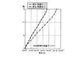
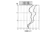
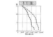
図7は、制振機構2を設置した場合(制震あり)と、設置してない場合(制震なし)における建物1の変位、図8は各階の加速度、図9は各階の層間変位、図10は各階の層せん断力をそれぞれ示している。
Below, the result of having performed the time history response analysis with respect to said vibration model is shown.
7 shows the displacement of the
これらの結果から、本実施形態の制振機構2を建物1に設けて制振構造Aにすることによって、最大で30%以上の応答低減効果が得られることが確認された。また、この制振機構2は、1階と3階の床梁1a、1cを連結しただけであるが、建物1全体の応答を効果的に抑制できることが確認された。なお、図7に示すように、制振機構2の回転慣性質量ダンパー3の変位が0.149mとなり、1階と3階の架構1a、1cの相対変位の3.4倍となるが、これは十分ダンパーのストロークでカバーできる範囲であり特に問題となる大きさではない。
From these results, it was confirmed that a response reduction effect of 30% or more can be obtained at the maximum by providing the
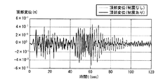
また、図11は建物1の頂部変位の時間変化、図12は頂部加速度の時間変化、図13は7階における層間変位の時間変化を示している。
11 shows the time change of the top displacement of the
これらの結果から、いずれも制振機構2を付加することで大きな応答低減効果が得られることが確認された。また、振動が励起されていく過程での応答低減はあまり認められないが、その後に続く、特に50秒以降で一定周期の揺れ(後揺れ)が効果的に低減されることが確認された。
From these results, it was confirmed that a large response reduction effect can be obtained by adding the
したがって、本実施形態の制振構造Aにおいては、制振機構2が回転慣性質量ダンパー3と付加バネ4を直列に接続して構成されているため、TMDと同様に、回転慣性質量ダンパー3の錘体3aの回転慣性を利用し、付加振動系となる制振機構Aの固有振動数を建物1と同調することで、建物1に作用した振動エネルギーを効果的に消費して建物1の応答を低減させることができる。
Therefore, in the vibration damping structure A of the present embodiment, since the
また、この制振機構2を、複数階に跨って(複数層に跨って)中間層の架構1bを挟んで上下に位置する上層と下層の床梁(架構)1a、1cに接続して設けることで、建物1の外周部(外側)や建物1内の上下に連通する吹き抜け部(床開口部)などに設置できる。このため、従来の制震ダンパーのように架構内(層間)に設置したり、従来のTMDのように建物1の頂部近傍に設置するものと比較し、設置箇所の制約が小さくなり、建築計画を行う上でその配置を容易に決めることが可能になる。
Further, the
さらに、この制振機構2を、特定箇所(本実施形態では1階床から3階床の間)にのみ設置することで、建物1全体の応答を低減することが可能になる。このとき、制振機構2を複数階に跨って設けることにより、1層だけでは層間変位が小さい場合においても、複数層全体の相対変位(この間の層間変位の合計となる比較的大きな相対変位)を制振機構2に作用させることが可能になるため、大きな制振効果を発揮させることが可能になる。また、特に、地震動の継続時間が長く、後揺れが問題になる場合には、絶大な応答低減効果を得ることが可能である。また、風荷重など長時間にわたり1次モードが卓越する振動を効果的に抑制できるため、建物1の居住性を向上させることが可能である。
Furthermore, the response of the
これにより、従来のように、各階(各層)ごとに制震ダンパー(層間ダンパー、ブレースダンパーや制震壁などの制震機構)を設置する場合と比較し、制振機構2の設置台数を大幅に減らすことが可能になる。よって、建物1への荷重負荷を軽減して、低コストで確実に且つ好適に耐振性能を向上させることが可能になる。
As a result, the number of installed damping
さらに、付加バネ4(付加バネ4の剛性k0)を調整することによって、制振機構2の固有振動数を容易に調整することが可能である。このため、例えば建物1の1次固有振動に制振機構2の固有振動数を容易に同調させることができ、建物1に作用した1次モードの振動エネルギーを確実に吸収して減衰させ、建物1の応答を低減させることが可能になる。また、このとき、制振機構2がTMDと同様に慣性質量効果を利用して振動エネルギーを減衰させるものであるため、微小振幅から制振効果を発揮させることが可能である。
Furthermore, the natural frequency of the
また、制振機構2が例えばオイルダンパーなどの付加減衰装置5を備えて構成されているため、回転慣性質量ダンパー3による慣性質量効果に加えてこの付加減衰装置5による減衰効果によって、さらに建物1に作用した振動エネルギーを減衰させて建物1の応答を低減させることが可能になる。
In addition, since the
このとき、付加減衰装置5の減衰定数C0を44kN/kineと桁違いに小さくしても建物1の応答を低減させることが可能である。このため、従来の制震ダンパーと比べて付加減衰装置5の減衰は小さくてよく、安価なダンパーを付加減衰装置5として使用できる。
At this time, it is possible to reduce the response of the
さらに、本実施形態のように建物1の最下部(1階から3階の間)に制振機構2を設けることで、建物頂部に設置する従来のTMDのように建物1への荷重負荷が大きくなることがなく、制振機構2の自重や反力処理を容易に行うことも可能である。
Furthermore, by providing the
以上、本発明に係る制振構造の第1実施形態について説明したが、本発明は上記の実施形態に限定されるものではなく、その趣旨を逸脱しない範囲で適宜変更可能である。例えば、本実施形態では、制振機構2の固有振動数f0を建物1の1次固有振動数に同調させるものとしたが、本発明の制振構造は、制振機構2の固有振動数f0を建物1の2次や3次の高次の振動数に同調させるようにしたり、建物1内に収納され、振動を嫌う装置機器類の固有振動数に同調させて、任意の固有振動数の揺れを低減させるために適用してもよい。
The first embodiment of the vibration damping structure according to the present invention has been described above. However, the present invention is not limited to the above-described embodiment, and can be changed as appropriate without departing from the spirit of the present invention. For example, in the present embodiment, the natural frequency f 0 of the
また、本実施形態では、付加減衰装置5が付加バネ4と並列に配置して設けられているものとしたが、回転慣性質量ダンパー3と並列に配しても本実施形態と同様の効果を得ることが可能である。また、特定の振動数で加振される場合には付加減衰装置5を備えずに制振機構2を構成してもよい。
Further, in the present embodiment, the additional damping
さらに、本実施形態では、制振機構2が1階と3階の床梁1a、1cに接続して設けられているものとしたが、例えば地震時に層間変位が大きくなる階を含めるようにして制振機構2を設置することが効果的であり、制振機構2を設置する階を限定する必要はない。また、制振機構2を特定の階間にだけ設置することに限定せず、建物1内の全ての層に配置したり、複数の制振機構2を例えば1階と3階の間、4階と6階の間というように不連続に配置してもよい。
Further, in the present embodiment, the
また、本実施形態では、回転慣性質量ダンパー3が、錘体3aと外枠3bとを備え、この錘体3aを回転軸3cによって回動自在に支持して構成されているものとしたが、回転慣性質量ダンパー3は、必ずしもこのように構成されていなくてもよく、周知の他の回転慣性質量ダンパーを採用してもよい。
In the present embodiment, the rotary
ついで、図14及び図15を参照し、本発明の第2実施形態に係る制振構造について説明する。本実施形態においては、第1実施形態と同様の構成に対して同一符号を付し、その詳細な説明を省略する。 Next, a vibration damping structure according to the second embodiment of the present invention will be described with reference to FIGS. In this embodiment, the same code | symbol is attached | subjected with respect to the structure similar to 1st Embodiment, and the detailed description is abbreviate | omitted.
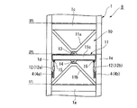
本実施形態の制振構造Bは、図14に示すように、第1実施形態と同様、建物1の1階(1FL)と2階(2FL)の複数階に跨って(建物1の複数層に跨って)、制振機構10を設置して構成されている。
As shown in FIG. 14, the vibration damping structure B of the present embodiment straddles the first floor (1FL) and the second floor (2FL) of the building 1 (several layers of the building 1) as in the first embodiment. The
本実施形態の制振機構10は、変位拡大機構11と回転慣性質量ダンパー12と付加バネ4とからなり、変位拡大機構11は、上下一対のV型鉄骨ブレース11a、11bと変位拡大部材11cとを備えて構成されている。
The
そして、変位拡大機構11の一方のV型鉄骨ブレース11aは、両端部を2階の床梁(中間層の架構1b)を挟んで上方に位置する3階(3FL)の床梁(上層の架構1c)に固定して設置されている。また、他方のV型鉄骨ブレース11bが、両端部を2階の床梁1bを挟んで下方に位置する1階の床梁(下層の架構1a)に固定して設置されている。
One V-shaped
変位拡大部材11cは、例えばH形鋼であり、一方のV型鉄骨ブレース11aの下端と他方のV型鉄骨ブレース11bの上端の間に配置されている。そして、この変位拡大部材11cは、その長さ方向中央において一方のV型鉄骨ブレース11aの下端と他方のV型鉄骨ブレース11bの上端とにそれぞれ回転軸(ピン)13、14を介して回転可能に接続して支持されている。これにより、変位拡大部材11cは、建物1に振動エネルギーが作用していない状態で水平に保持され、1階の床梁1aと3階の床梁1cとが横方向に相対変位して一方のV型鉄骨ブレース11aと他方のV型鉄骨ブレース11bとが横方向に相対変位するとともに、図15に示すように回転軸13、14を中心に上下方向に回転する。
The
一方、回転慣性質量ダンパー12は、ボールネジとフライホイール(回転錘、錘体)を組み合わせて構成され、図14に示すように、その下端に高減衰積層ゴムなどの付加減衰機能を併せもつ付加バネ4が直列に接続されている。そして、本実施形態の制振機構10においては、直列に接続した回転慣性質量ダンパー12と付加バネ4が2組設けられており、一方の付加バネ4(4a)が1階の左右一対の柱1d、1eの一方の柱(下層の架構)1dに、他方の付加バネ4(4b)が他方の柱(下層の架構)1eにそれぞれ固定されている。また、一方の付加バネ4aに接続した一方の回転慣性質量ダンパー12(12a)の上端が変位拡大部材11cの長さ方向一端側に回転軸(ピン)15を介して回転可能に接続されている。さらに、他方の付加バネ4bに接続した他方の回転慣性質量ダンパー12(12b)の上端が変位拡大部材11cの長さ方向他端側に回転軸(ピン)16を介して回転可能に接続されている。
On the other hand, the rotary
このように構成した本実施形態の制振機構10(制振構造B)においては、図15に示すように、例えば地震によって建物1に振動エネルギーが作用し、1階の床梁1aと3階の床梁1cとが横方向に相対変位して変位拡大部材11cが回転すると、1階の床梁1aと3階の床梁1cの相対変位量t1に対して変位拡大部材11cの両端側の上下方向の変位量t2(変位拡大機構11の変位量)が大きくなる。このため、変位拡大部材11cの両端側にそれぞれ回転可能に接続した各回転慣性質量ダンパー12(12a、12b)と付加バネ4との合計の変位量t2が1階の床梁1aと3階の床梁1cの相対変位量t1に対して大きくなる。
In the vibration damping mechanism 10 (damping structure B) of the present embodiment configured as described above, as shown in FIG. 15, vibration energy acts on the
これにより、1階の床梁1aと3階の床梁1cに回転慣性質量ダンパー12を直接接続した場合と比較し、1階の床梁1aと3階の床梁1cの相対変位に対して回転慣性質量ダンパー12が大きな慣性質量効果を発揮することになる。
Thereby, compared with the case where the rotary
したがって、本実施形態の制振構造Bによれば、建物1に振動エネルギーが作用して床梁1a、1cが相対変位した際に、この相対変位量t1よりも大きな変位量t2で変位拡大機構11が変位するため、この変位拡大機構11に接続した回転慣性質量ダンパー12を大きく変位させることが可能になる。これにより、回転慣性質量ダンパー12が床梁1a、1cの相対変位に対して大きな慣性質量効果を発揮することになり、より確実に且つ効率的に建物1に作用した振動エネルギーを減衰させて建物1の応答を低減させることが可能になる。
Therefore, according to the vibration damping structure B of this embodiment, when vibration energy acts on the
また、制振機構10が建物1の複数階に跨って設けられることで、第1実施形態と同様に、設置箇所を限定することなく、少ない設置台数で、確実に建物1全体の応答を低減させる大きな制振効果を得ることが可能になる。これにより、建築計画を行う上で、制振機構10の配置を容易に決めることができ、建物1への荷重負荷を軽減して、低コストでさらに耐振性能を向上させることが可能になる。
In addition, since the
なお、本発明は上記の第2実施形態に限定されるものではなく、第1実施形態に示した変更例を含め、その趣旨を逸脱しない範囲で適宜変更可能である。例えば、本実施形態では、変位拡大機構11が上下一対のV型鉄骨ブレース11a、11bとH形鋼からなる変位拡大部材11cとで構成されているものとしたが、変位拡大機構11は、建物1の床梁1a、1cの相対変位量t1よりも大きな変位量t2で変位し、回転慣性質量ダンパー12と付加バネ4とを直列にしてこの大きな変位量t2で変位させることが可能であれば、特にその構成を限定する必要はない。
In addition, this invention is not limited to said 2nd Embodiment, Including the example of a change shown in 1st Embodiment, it can change suitably in the range which does not deviate from the meaning. For example, in the present embodiment, the
また、本実施形態では、回転慣性質量ダンパー12の慣性質量効果によって建物1に作用した振動エネルギーを減衰させるように構成しているが、第1実施形態と同様に、高減衰ゴムを用いないでオイルダンパーなどの付加減衰装置を設けて、慣性質量効果に加えこの付加減衰装置の減衰効果で振動エネルギーを減衰させるようにしてもよい。例えば図16に示すように、一端を建物1の架構に、他端を変位拡大機構11の変位拡大部材11cに接続して付加減衰装置17を設置することで、減衰効果を発揮させることが可能である。そして、この場合、建物1に振動エネルギーが作用して床梁1a、1cが相対変位した際に、回転慣性質量ダンパー12と同様に、この相対変位量t1よりも大きな変位量t2で付加減衰装置17が変位することになる。このため、付加減衰装置17が床梁1a、1cの相対変位に対して大きな減衰効果を発揮することになり、さらに確実に且つ効率的に建物1に作用した振動エネルギーを減衰させて建物1の応答を低減させることが可能になる。
In the present embodiment, the vibration energy acting on the
1 建物
1a 1階の床梁(下層の架構)
1b 2階の床梁(中間層の架構)
1c 3階の床梁(上層の架構)
1d 1階の柱(下層の架構)
1e 1階の柱(下層の架構)
2 制振機構
3 回転慣性質量ダンパー
3a 錘体
3b 外枠
3c 回転軸
4 付加バネ
5 付加減衰装置
10 制振機構
11 変位拡大機構
11a 一方のV型鉄骨ブレース
11b 他方のV型鉄骨ブレース
11c 変位拡大部材
12 回転慣性質量ダンパー
13 回転軸
14 回転軸
15 回転軸
16 回転軸
17 付加減衰装置
A 制振構造
B 制振構造
t1 架構の相対変位量
t2 変位拡大機構の変位量
1
1b Floor beams on the 2nd floor (intermediate frame)
1c 3rd floor floor beam (upper frame)
1d First floor pillar (lower frame)
1e 1st floor pillar (lower frame)
2 Damping
Claims (3)
前記制振機構が、回転慣性質量ダンパーと付加バネを直列に接続して構成され、前記建物の中間層の架構を挟んで上下に位置する上層と下層の架構に接続して、複数層に跨って設けられていることを特徴とする制振構造。 A vibration control structure in which a vibration control mechanism for attenuating vibration energy applied to the building is installed in a multilayer structure building,
The vibration damping mechanism is configured by connecting a rotary inertia mass damper and an additional spring in series, and is connected to upper and lower frames positioned above and below the intermediate layer frame of the building and spans a plurality of layers. Damping structure characterized by being provided.
前記制振機構が、付加減衰装置を備え、該付加減衰装置を前記回転慣性質量ダンパーあるいは前記付加バネに対して並列に接続して構成されていることを特徴とする制振構造。 The vibration damping structure according to claim 1,
A vibration damping structure, wherein the vibration damping mechanism includes an additional damping device, and the additional damping device is connected in parallel to the rotary inertia mass damper or the additional spring.
前記制振機構が、前記上層と下層の架構に接続して設けられて前記上層と下層の架構が相対変位するとともに該上層と下層の架構の相対変位量よりも大きな変位量を生じる変位拡大機構を備えており、
前記回転慣性質量ダンパーと前記付加バネ、及び/又は前記付加減衰装置が前記変位拡大機構に接続して設けられていることを特徴とする制振構造。 In the vibration damping structure according to claim 1 or 2,
A displacement enlarging mechanism in which the vibration damping mechanism is provided in connection with the upper and lower frames so that the upper and lower frames are relatively displaced and the displacement is larger than the relative displacement of the upper and lower frames. With
The vibration damping structure, wherein the rotary inertia mass damper, the additional spring, and / or the additional damping device are provided in connection with the displacement magnifying mechanism.
Priority Applications (1)
| Application Number | Priority Date | Filing Date | Title |
|---|---|---|---|
| JP2007331611A JP2009155801A (en) | 2007-12-25 | 2007-12-25 | Vibration control structure |
Applications Claiming Priority (1)
| Application Number | Priority Date | Filing Date | Title |
|---|---|---|---|
| JP2007331611A JP2009155801A (en) | 2007-12-25 | 2007-12-25 | Vibration control structure |
Publications (1)
| Publication Number | Publication Date |
|---|---|
| JP2009155801A true JP2009155801A (en) | 2009-07-16 |
Family
ID=40960099
Family Applications (1)
| Application Number | Title | Priority Date | Filing Date |
|---|---|---|---|
| JP2007331611A Pending JP2009155801A (en) | 2007-12-25 | 2007-12-25 | Vibration control structure |
Country Status (1)
| Country | Link |
|---|---|
| JP (1) | JP2009155801A (en) |
Cited By (6)
| Publication number | Priority date | Publication date | Assignee | Title |
|---|---|---|---|---|
| JP2011141026A (en) * | 2009-12-10 | 2011-07-21 | Shimizu Corp | Tmd mechanism |
| JP2012041799A (en) * | 2010-08-23 | 2012-03-01 | Shimizu Corp | Vibration control reinforcement structure of existing building |
| JP2013044155A (en) * | 2011-08-24 | 2013-03-04 | Shimizu Corp | Vibration control structure |
| EP2767653A3 (en) * | 2013-02-14 | 2015-12-30 | Hitachi-GE Nuclear Energy, Ltd. | Higher-order vibration control device |
| JP2022110464A (en) * | 2021-01-18 | 2022-07-29 | 株式会社竹中工務店 | Vibration control structure |
| CN115613861A (en) * | 2022-09-08 | 2023-01-17 | 河南大方重型装备有限公司 | Effectual steel construction factory building of resistance to compression shock attenuation |
Citations (2)
| Publication number | Priority date | Publication date | Assignee | Title |
|---|---|---|---|---|
| JP2001349094A (en) * | 2000-06-08 | 2001-12-21 | Sekisui House Ltd | Synchronized pendulum damping device |
| JP2004263419A (en) * | 2003-02-28 | 2004-09-24 | Edogawa Lumber Industrial Co Ltd | Damping device |
-
2007
- 2007-12-25 JP JP2007331611A patent/JP2009155801A/en active Pending
Patent Citations (2)
| Publication number | Priority date | Publication date | Assignee | Title |
|---|---|---|---|---|
| JP2001349094A (en) * | 2000-06-08 | 2001-12-21 | Sekisui House Ltd | Synchronized pendulum damping device |
| JP2004263419A (en) * | 2003-02-28 | 2004-09-24 | Edogawa Lumber Industrial Co Ltd | Damping device |
Cited By (7)
| Publication number | Priority date | Publication date | Assignee | Title |
|---|---|---|---|---|
| JP2011141026A (en) * | 2009-12-10 | 2011-07-21 | Shimizu Corp | Tmd mechanism |
| JP2012041799A (en) * | 2010-08-23 | 2012-03-01 | Shimizu Corp | Vibration control reinforcement structure of existing building |
| JP2013044155A (en) * | 2011-08-24 | 2013-03-04 | Shimizu Corp | Vibration control structure |
| EP2767653A3 (en) * | 2013-02-14 | 2015-12-30 | Hitachi-GE Nuclear Energy, Ltd. | Higher-order vibration control device |
| JP2022110464A (en) * | 2021-01-18 | 2022-07-29 | 株式会社竹中工務店 | Vibration control structure |
| JP7650153B2 (en) | 2021-01-18 | 2025-03-24 | 株式会社竹中工務店 | Vibration-damping structure |
| CN115613861A (en) * | 2022-09-08 | 2023-01-17 | 河南大方重型装备有限公司 | Effectual steel construction factory building of resistance to compression shock attenuation |
Similar Documents
| Publication | Publication Date | Title |
|---|---|---|
| JP4968682B2 (en) | Vibration reduction mechanism and specification method thereof | |
| US20110283653A1 (en) | Fork Configuration Dampers and Method of Using Same | |
| JP6694672B2 (en) | Vibration control device and building equipped with the same | |
| JP2013044155A (en) | Vibration control structure | |
| JP2009007916A (en) | Damping structure and its specification method | |
| JP5316849B2 (en) | Damping structure | |
| JP3828695B2 (en) | Seismic control wall of a three-story house | |
| JP6456774B2 (en) | Vibration control structure | |
| JP5574330B2 (en) | Seismic isolation structure | |
| JP2017089151A (en) | Vibration control structure of building | |
| JP5574326B2 (en) | Structural seismic control structure | |
| JP5495013B2 (en) | Vibration control mechanism | |
| JP2011038294A (en) | Additional mass seismic response control building | |
| JP4277649B2 (en) | Composite damper and column beam structure | |
| JP2010242449A (en) | Seismic retrofit structure and seismic retrofit method for existing buildings | |
| JP2012046936A (en) | Vertical vibration control system of building floor | |
| JP7037320B2 (en) | Vibration control building | |
| JP3677706B2 (en) | Seismic isolation and control structure | |
| JP3248684B2 (en) | Damping structure | |
| JP6853869B2 (en) | Vibration control structure of the building | |
| JP3671317B2 (en) | Seismic isolation mechanism | |
| Komur et al. | Nonlinear dynamic analysis of isolated and fixed-base reinforced concrete structures | |
| JP6098866B2 (en) | Vertical vibration control structure | |
| JP2011140970A (en) | Base isolation construction and structure | |
| JP2005090101A (en) | Seismic response control structure |
Legal Events
| Date | Code | Title | Description |
|---|---|---|---|
| A621 | Written request for application examination |
Free format text: JAPANESE INTERMEDIATE CODE: A621 Effective date: 20100528 |
|
| A131 | Notification of reasons for refusal |
Free format text: JAPANESE INTERMEDIATE CODE: A131 Effective date: 20120821 |
|
| A02 | Decision of refusal |
Free format text: JAPANESE INTERMEDIATE CODE: A02 Effective date: 20121221 |