JP2009118054A - Power supply system for terminal network controller - Google Patents
Power supply system for terminal network controller Download PDFInfo
- Publication number
- JP2009118054A JP2009118054A JP2007287324A JP2007287324A JP2009118054A JP 2009118054 A JP2009118054 A JP 2009118054A JP 2007287324 A JP2007287324 A JP 2007287324A JP 2007287324 A JP2007287324 A JP 2007287324A JP 2009118054 A JP2009118054 A JP 2009118054A
- Authority
- JP
- Japan
- Prior art keywords
- power supply
- terminal network
- voltage
- output
- network control
- Prior art date
- Legal status (The legal status is an assumption and is not a legal conclusion. Google has not performed a legal analysis and makes no representation as to the accuracy of the status listed.)
- Pending
Links
Images


Abstract
Description
本発明は、通信回線を利用して遠隔検針を行うテレメータシステムの端末網制御装置用電源装置に関する。 The present invention relates to a power supply device for a terminal network control device of a telemeter system that performs remote meter reading using a communication line.
図7には電池駆動される端末網制御装置の全体構成図が示されている。図7に示すように、ガス、水道、電気などのメータを、電話回線などの通信回線を利用してセンタ側より遠隔検針するテレメータシステムにおいては、端末網制御装置(以下、「NCU」と略す)は、主として電池駆動である。その理由は、NCUの動作回数が月に数回に限られるというように動作頻度が低く、且つ待機時の消費電力がマイクロアンペアオーダーと少ないため、電池で運用しても10年程度の間にわたって動作可能なことである。 FIG. 7 shows an overall configuration diagram of a battery-driven terminal network control device. As shown in FIG. 7, a terminal network controller (hereinafter abbreviated as “NCU”) is used in a telemeter system in which meters such as gas, water, and electricity are remotely metered from the center side using a communication line such as a telephone line. ) Is mainly battery powered. The reason for this is that the frequency of operation of the NCU is low, such as being limited to several times a month, and the standby power consumption is as low as microamperes. It is possible to operate.
しかしながら、電池は消耗するため、特許文献1にあるように、NCUが電池切れを起こす前にセンタに電池末期であることを通報し、それを受けてNCUに電池交換などのメンテナンスを行うことによって、システムが長期に渡って円滑に運用できるようにしている。特許文献1に記載されている自動検針端末装置は、電圧検知部が電池電源部の電池電圧を所定の電圧と比較することで電池の電圧低下を検出したときに、電話回線からダイヤルしてセンタ側に電池低下情報を通報し、更に、通報後、所定時間経過するまでは端末装置を正常に動作させてメンテナンス期間を確保し、所定時間経過すると端末装置を自動的に停止させて、端末装置の電圧低下に起因した誤作動を防止することを図っている。
However, since the battery is exhausted, as described in
その一方で、特定用途で頻繁に動作させるNCUや、携帯電話の無線通信を利用したNCUなどの場合は、待機時の消費電力がミリアンペアオーダーと大きく、電池の消耗が早くなる。したがって、頻繁にNCUのメンテナンスが必要となるか、或いは、NCUに多くの電池を搭載しなければならなくなる。 On the other hand, in the case of an NCU that is frequently operated for a specific purpose or an NCU that uses wireless communication of a mobile phone, power consumption during standby is as large as milliampere, and battery consumption is accelerated. Therefore, frequent maintenance of the NCU is required, or many batteries must be mounted on the NCU.
このような場合は、商用電源を利用するほうがメンテナンス、コスト、大きさの面で有利となる。例えば、電池駆動のNCUに対して商用電源を利用する場合は、商用電源を電池と同じ直流電圧にレギュレートするNCU用電源装置を用意し、NCUの電池接続口に接続する。また商用電源の代わりに太陽電池と蓄電池を利用した電源なども考えられる。 In such a case, the use of a commercial power supply is advantageous in terms of maintenance, cost, and size. For example, when a commercial power source is used for a battery-driven NCU, an NCU power supply device that regulates the commercial power source to the same DC voltage as that of the battery is prepared and connected to the battery connection port of the NCU. A power source using a solar battery and a storage battery instead of a commercial power source is also conceivable.
テレメータシステムにおいて、端末網制御装置用電源装置が商用電源駆動の電源装置である場合、コンセントがユーザーによって抜かれた場合や停電時には動作不能となるので、そうした電源供給の確実性の点では電池駆動に劣る。それをカバーするため、補助電源としてバックアップ電池や、大容量キャパシタを持つ電源装置がある。 In a telemeter system, if the power supply for the terminal network control device is a commercial power supply power supply, it will become inoperable when the outlet is pulled out by the user or during a power failure. Inferior. In order to cover this, there are backup batteries and power supply devices with large capacitors as auxiliary power supplies.
このような補助電源付きの電源装置でも、コンセントが抜かれた場合などには、至急ユーザーに連絡するなどメンテナンスを行わなければ補助電源も使い果たしてしまう事態となる。そのため、コンセント抜けや停電を検知したときには、センタに通報しなければならない。また、補助電源がバックアップ電池の場合、補助電源の動作頻度によってはバックアップ電池も消耗し、補助電源の機能を果たさなくなってしまう。そのため、バックアップ電池の消耗を検知したときには、センタに通報しなければならない。 Even in such a power supply device with an auxiliary power supply, when the outlet is unplugged, the auxiliary power supply will be used up unless maintenance is performed such as contacting the user immediately. For this reason, when an outlet or power failure is detected, the center must be notified. Further, when the auxiliary power source is a backup battery, the backup battery is also consumed depending on the operation frequency of the auxiliary power source, and the function of the auxiliary power source cannot be performed. Therefore, when exhaustion of the backup battery is detected, the center must be notified.
他に、太陽電池と蓄電池を利用した電源装置も考えられるが、こうした電源装置では、日射量不足による充電量の不足や、蓄電池の充放電回数、使用時間による寿命がきた場合には、それぞれセンタに通報しなければならない。 In addition, power supply devices using solar cells and storage batteries are also conceivable. However, in such power supply devices, if the amount of charge due to insufficient solar radiation, the number of times the storage battery is charged / discharged, or the life due to usage time is reached, the power supply device is You must report to.
つまり、テレメータシステムを円滑に運用するためには、上記の電源装置のどれを採用した場合でも、それぞれセンタに通報する必要な事態が生じる。
ところがこれらの通報を行うためには、停電や寿命などそれぞれの異常の情報をNCUに伝える必要がある。情報を伝えるには電源装置からNCUへの信号線の設置や、NCUのソフトウェアの変更が必要となるが、既存のNCUの場合には大幅な改造となり、対策として現実的ではない。
However, in order to make these notifications, it is necessary to inform the NCU of information on each abnormality such as a power failure and a life span. In order to convey information, it is necessary to install a signal line from the power supply unit to the NCU and to change the software of the NCU. However, in the case of an existing NCU, it is a significant modification, which is not practical as a countermeasure.
そこで、電源装置が異常状態にあることの情報を通報するために、電源装置の状態が停電又はバックアップ電池の寿命である等の異常状態に変化するときに、その電源状態を端末網制御装置への出力に反映させる点で解決すべき課題がある。 Therefore, in order to report information that the power supply device is in an abnormal state, when the power supply device state changes to an abnormal state such as a power failure or the life of the backup battery, the power supply state is sent to the terminal network control device. There is a problem to be solved in that it is reflected in the output.
この発明の目的は、電源装置の状態が異常状態に変化するときに、その電源状態を端末網制御装置への出力に反映させることにより、電源装置が異常状態に変化したことついての情報がセンタに通報され、早急な電源回復を図るメンテナンスを実施することを可能にする、テレメータシステムにおける端末網制御装置用電源装置を提供することである。 The object of the present invention is to reflect the power supply state in the output to the terminal network control device when the state of the power supply device changes to an abnormal state, so that information about the change of the power supply device to the abnormal state is centered. It is to provide a power supply device for a terminal network control device in a telemeter system that makes it possible to carry out maintenance for prompt power recovery.
主なNCUは電池駆動であるため、電池電圧の低下を検知し、センタへ通報する機能を持っている。本発明ではこの機能を利用する。即ち、本発明による端末網制御装置用電源装置は、通信回線を利用して遠隔検針を行うテレメータシステムの端末網制御装置に用いられる電源装置であって、端末網制御装置に出力される電源装置の出力電圧値が当該電源装置の電源状態に応じて可変であることを特徴としている。 Since the main NCU is battery-driven, it has a function of detecting a drop in battery voltage and reporting to the center. The present invention uses this function. That is, the power supply apparatus for a terminal network control apparatus according to the present invention is a power supply apparatus used in a terminal network control apparatus of a telemeter system that performs remote meter reading using a communication line, and is a power supply apparatus that is output to the terminal network control apparatus The output voltage value is variable in accordance with the power supply state of the power supply apparatus.
通常時は電源装置からNCUの定格電圧を出力する。例えばリチウム電池1本で動作のNCUの場合は3Vである。この電圧は、端末網制御装置が通常動作する第1電圧値とされる。
電源装置の異常時、つまり停電やコンセント抜けの検知、バックアップ電池の消耗、充電量不足、蓄電池の寿命など、センタに通報する必要のある場合は、電源装置から出力する電圧を意図的に低下させて出力する。低下させる電圧値は、NCUが電池電圧低下と判断してその旨を発呼する第2電圧値とする。例えば、リチウム電池1本で動作するNCUの場合はNCUによって異なるが2.4Vなどとなる。
In normal times, the rated voltage of the NCU is output from the power supply unit. For example, in the case of an NCU operating with one lithium battery, it is 3V. This voltage is the first voltage value at which the terminal network control device normally operates.
When it is necessary to report to the center when there is an abnormality in the power supply, that is, when a power outage or outlet disconnection is detected, the backup battery is exhausted, the amount of charge is insufficient, the life of the storage battery, etc., the voltage output from the power supply is intentionally reduced. Output. The voltage value to be decreased is a second voltage value that the NCU determines that the battery voltage has decreased and calls that effect. For example, in the case of an NCU that operates with a single lithium battery, the voltage is 2.4 V although it varies depending on the NCU.
また、電源装置の内部にバックアップ電池を具備している場合には、バックアップ電池が寿命の場合は第2電圧値を出力し、それ以外の場合は第1電圧値を出力することができる。また、電源装置の内部にバックアップ電池を具備している場合には、バックアップ電池の電圧が一定電圧以上であることに応じて第1電圧値を出力し、バックアップ電池の電圧が一旦一定電圧以下になることに応じて、以後電圧値が一定電圧を超えて上昇しても、第2電圧値を継続して出力することができる。 Further, when the backup battery is provided inside the power supply device, the second voltage value can be output when the backup battery is at the end of its life, and the first voltage value can be output otherwise. In addition, when the backup battery is provided in the power supply device, the first voltage value is output in response to the backup battery voltage being equal to or higher than a certain voltage, and the backup battery voltage is once lowered below the certain voltage. Accordingly, the second voltage value can be continuously output even if the voltage value subsequently increases beyond a certain voltage.
また、電源装置が商用電源を電源とし、商用電源からの電源供給が停電又はコンセント抜けに起因して途絶えた場合に作動するバックアップ手段を具備している場合には、通常は商用電源に基づいて第1電圧値を出力し、商用電源からの電源供給が途絶えることに応じてバックアップ手段に基づいて第2電圧値を出力することができる。また、電源装置が内部に蓄電池を具備している場合には、通常は第1電圧値を出力し、蓄電池の充放電回数が一定以上になった場合に第2電圧値を出力することができる。 In addition, when the power supply device has a commercial power source as a power source and has backup means that operates when the power supply from the commercial power source is interrupted due to a power failure or disconnection from the outlet, it is usually based on the commercial power source. The first voltage value can be output, and the second voltage value can be output based on the backup means in response to the interruption of power supply from the commercial power supply. Further, when the power supply device has a storage battery therein, the first voltage value is normally output, and the second voltage value can be output when the number of times of charging / discharging of the storage battery exceeds a certain level. .
また、電源装置が通常は第1電圧値を出力し、電源装置の動作時間が一定以上になった場合に第2電圧値を出力することができる。また、通常は第1電圧値を出力し、電源装置に異常が発生した場合に第2電圧値を出力することができる。 In addition, the power supply device normally outputs the first voltage value, and the second voltage value can be output when the operation time of the power supply device becomes a certain value or more. Further, the first voltage value is normally output, and the second voltage value can be output when an abnormality occurs in the power supply device.
更に、この端末網制御装置用電源装置においては、商用電源又は蓄電池などの主電源からの停電又は充電不足等の電源異常を検知する主電源異常検知部と、蓄電池又はバックアップ電池を備える場合はそのバックアップ電池の電池消耗検知部と、出力電圧制御部とを備え、出力電圧制御部は、通常は第1電圧値を出力し、主電源異常検知部からの出力信号又は電池消耗検知部からの出力信号に基づいて第2電圧値を出力する構成にできる。 Further, in this power supply device for terminal network control device, if it has a main power supply abnormality detection unit for detecting a power supply abnormality such as a power failure from a main power supply such as a commercial power supply or a storage battery, or insufficient charging, and a storage battery or a backup battery, A backup battery battery consumption detection unit and an output voltage control unit are provided. The output voltage control unit normally outputs a first voltage value, and an output signal from the main power supply abnormality detection unit or an output from the battery consumption detection unit. The second voltage value can be output based on the signal.
電源装置の異常時にこのような電圧操作をすることによって、NCUは、電池電圧低下と判断し、センタへ通報する。センタ側では、NCUに電池ではなく電源装置を接続していることを把握していれば、電池電圧低下通報ではなく、電源装置の異常であると解釈でき、メンテナンスを行うことができる。 By performing such a voltage operation when the power supply apparatus is abnormal, the NCU determines that the battery voltage has dropped and notifies the center. If the center knows that the power supply device is connected to the NCU instead of the battery, it can be interpreted as a power supply device abnormality rather than a battery voltage drop notification, and maintenance can be performed.
例えば、商用電源とバックアップ電池で構成される電源装置では、通報があった場合、停電、コンセント抜けかバックアップ電池の消耗と考えられる。同時に多数のNCUから通報が来た場合は地域的な停電と考えられ、この場合は停電の復旧を待つ事となる。通報が一つのNCUの場合はコンセント抜け又はバックアップ電池の消耗が疑われるためユーザーに連絡し、コンセント抜けがないか確認していただく。コンセント抜けでなければバックアップ電池の消耗ということになるので出動して対応する。 For example, in a power supply device composed of a commercial power source and a backup battery, if there is a report, it is considered that a power failure, disconnection from the outlet, or the backup battery is exhausted. If a number of NCU reports are received at the same time, it is considered a regional power outage. In this case, the recovery from the power outage is awaited. If the notification is for one NCU, it is suspected that the outlet has been disconnected or the backup battery has been exhausted. If the outlet is not disconnected, it means that the backup battery is exhausted.
以上のように、この発明によれば、電源装置の出力電圧値が電源装置の停電・コンセント抜け、或いは電池消耗や使用履歴等の電源状態に応じて可変とされるので、電源装置の電源状態が異常である旨の異常情報が端末網制御装置に伝わったこととなり、電源装置の種類により適時にメンテナンスを行うことによってシステムの円滑な運用が可能となる。また、本発明によるとNCUに信号線の追加やソフトウェアの更新などの変更を必要とせず、既存のシステムに適用可能である。 As described above, according to the present invention, since the output voltage value of the power supply device can be changed according to the power supply state such as power failure / outlet of the power supply device, battery consumption or usage history, the power supply state of the power supply device As a result, abnormality information indicating that is abnormal is transmitted to the terminal network control device, and the system can be smoothly operated by performing maintenance in a timely manner depending on the type of the power supply device. Further, according to the present invention, the NCU does not require any change such as addition of a signal line or software update, and can be applied to an existing system.
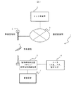
以下に、図面を参照して本発明の実施形態について説明する。図1は、この発明による端末網制御装置用電源装置が適用されるテレメータシステムの一例を示す全体構成図である。図2は図1に示す端末網制御装置のブロック図、図3は図2に示すブロック図に対応する回路図である。 Embodiments of the present invention will be described below with reference to the drawings. FIG. 1 is an overall configuration diagram showing an example of a telemeter system to which a power supply device for a terminal network control device according to the present invention is applied. 2 is a block diagram of the terminal network control apparatus shown in FIG. 1, and FIG. 3 is a circuit diagram corresponding to the block diagram shown in FIG.
図1の示すテレメータシステム1において、センタ側装置2は通信回線網3を介して無線基地局4と接続されており、無線基地局4は、携帯電話無線仕様であって、端末網制御装置(以下、「NCU」と略す)5と無線通信6によってデータ通信可能である。NCU5は、その電源装置7から電力の供給を受け、水道、ガス、電気などのメータ8とデータ通信可能である。
In the
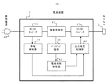
図2に示すように、図1に示す電源装置7においては、AC/DCコンバータ部11は、商用交流電源10のAC100Vを直流電圧にレギュレートする。本実施例では、バックアップ電池13より高い5Vにレギュレートしている。電源切替部12は、停電などに起因してAC/DCコンバータ11からの電圧が一定以下となった場合などに、バックアップ電池13が電源として使われるように動作する。AC/DCコンバータ11の出力電圧がバックアップ電池13の電圧より高い場合は、簡単に直列にダイオードを挿入するのみでも構成できる。後述する停電検知部14の信号を受けてトランジスタなどによるスイッチとしてもよい。
As shown in FIG. 2, in the
電池消耗検知部15は、バックアップ電池13の消耗の有無を検知する。停電検知部14の出力信号と電池消耗検知部15の出力信号は、出力電圧制御部16に入力される。DC/DCコンバータ部17は、出力電圧制御部16で制御された電圧を出力する。制御電圧の1つは本実施例のNCU5の定格電圧である3Vとし、もう1つはNCU5が電池電圧低下を検知する電圧である2.4Vとする。
The battery
DC/DCコンバータ17には出力電圧を任意に決められるように出力電圧制御部16からフィードバック入力がある。本実施例のDC/DCコンバータ17はフィードバック電圧が1.23Vであるので、所望の出力電圧を抵抗で分圧した値が1.23Vとなるような抵抗値を決めればよい。計算式で表すと、出力電圧=1.23×(1+R1/R2)となる。ここで、図3において出力電圧制御部16に示すように、R1は分圧抵抗のうち上側の抵抗1の抵抗値、R2は下側の抵抗2の抵抗値である。
The DC / DC converter 17 has a feedback input from the output
本実施例では、抵抗1を820kΩ、抵抗2を560kΩ、抵抗1と並列に置かれる抵抗1aを1.5MΩとしている。トランジスタ1がオフの場合は抵抗1と抵抗2の分圧となり、出力電圧は約3Vとなる。トランジスタ1がオンの時は抵抗1と抵抗1aの合成抵抗値である約530kΩと抵抗2の分圧となり、出力電圧は約2.4Vとなる。
つまり、DC/DCコンバータ部17は、出力電圧制御部16のトランジスタ1をオフとすればNCU5の定格電圧である3Vを、トランジスタ1をオンにすればNCU5が電池電圧低下を検知する電圧である2.4Vを出力する。
In this embodiment, the
That is, the DC / DC converter unit 17 is a voltage at which the rated voltage of the
停電検知部14は、商用電源10からの電源供給が途絶えた場合に出力電圧制御部16のトランジスタ1をオンする信号を出力する電圧検知回路1である。電圧検知回路1はトランジスタや電圧検知ICなどを利用して容易に実現できる。
The power
電池消耗検知部15は、電源装置7内のバックアップ電池13の消耗を検知した場合に出力電圧制御部16のトランジスタ1をオンする信号を出力する電圧検知回路2である。
The battery
電池消耗検知部15の具体的な構成においては、色々な方法がある。一つの方法として、バックアップ電池13の電圧値で消耗を判断する方法があるが、電池の電圧は放電深度、温度、負荷によって大きく変動する。動作時などの負荷の大きい時は電圧値が低下し、待機時などの負荷の小さい時は電圧値が回復していく。この性質のため、一定電圧を閾値として信号を出力した場合、動作中の特に負荷の大きい一瞬だけ信号を出力し、その他動作時や待機時などには電池の電圧が回復し信号を出力しないことが考えられ、結果としてDC/DCコンバータ17の出力電圧が不規則に変化することとなり、NCU5が不安定になる可能性が高い。それを避けるために電池電圧が一定電圧以下となった場合、出力信号をラッチする方法がよい。また、更には、新品の電池を交換した際に出力がラッチされたままでは電池交換が反映されないので、新品の電池電圧程度であれば出力信号のラッチを解除する回路を設けるのがよい。
There are various methods in the specific configuration of the battery
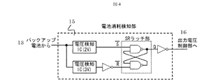
図4に電池消耗検知部15の一例をブロック図として示す。バックアップ電池13の電圧を2種類の電圧検知ICで検知する。低いほうの電圧値がラッチ電圧で2Vとし、高いほうの電圧値は解除電圧で3Vとする。バックアップ電池13の電圧が2Vを下回った場合は、出力電圧制御部16に信号を出力してラッチする。つまり、一旦、バックアップ電池13の電圧が2Vを下回れば、再び2Vを超えても信号を出力し続ける。また、新しいバックアップ電池13に交換した場合などにはラッチを解除しなければならないので、3Vを超えればラッチを解除するようになっている。
FIG. 4 shows an example of the
図5には、図4に示す電池消耗検知部15におけるバックアップ電池13の電圧と各部の出力波形例が示されている。バックアップ電池13の電圧が3V以上であれば、2種類の電圧検知ICの出力はいずれもH(QはL、Rの反転信号はL)であり、その結果、出力電圧制御部16への出力信号はH(トランジスタ1をOFF)となる。バックアップ電池13の電圧が3Vよりも低下(2V以上)すれば、電圧検知IC(3V)の出力がLとなる。したがって、Rの反転信号はHになるが、QはLのままであるので、出力電圧制御部16への出力信号はH(OFF)が維持される。バックアップ電池13の電圧が更に低下して、一旦2Vよりも低下すると、その後、2Vを回復して電圧検知IC(2V)がHになっても、QもRの反転信号も共にHとなり、出力電圧制御部16への出力信号はL(トランジスタ1をON)となり、その後もその状態が維持される。バックアップ電池13の新品への交換によって電圧が3Vを回復すると、当初の状態に復帰する。
FIG. 5 shows the voltage of the
このように、本実施例によれば、電源装置7は、通常時、NCU5の定格電圧である3Vを出力しているが、電源装置7の電源状態の異常、つまりコンセント抜けや停電、電源装置7に内蔵のバックアップ電池13の消耗が生じて、電源供給能力が通常ではない又はそれと見なし得る事態が生じたと判断される場合、NCU5への出力電圧を2.4Vに意図的に低下させる。NCU5は、電圧低下を受けて電池電圧低下と判断し、センタ側装置2にその旨を通報する。通報を受けたセンタ側装置2は、この通報を電源装置7の異常であると解釈する。電源装置7のメンテナンスを行うことによってシステムの円滑な運用を図ることができる。
As described above, according to the present embodiment, the
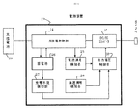
図6は、電源装置の他の実施形態を示すブロック図である。図6に示す電源装置21は、電源を太陽電池20から取り、鉛蓄電池、リチウムイオン電池、ニッケル水素電池などの蓄電池(2次電池)26に電力を蓄える電源装置である。このようなシステムの場合、日照不足による電力不足が懸念されるため、充電不足検知部27で電力不足を検知する。充電不足検知部27は、閾値電圧を1日以上下回った場合に、信号を出力電圧制御部36に出力するなどが考えられる。
FIG. 6 is a block diagram showing another embodiment of the power supply device. The
また、蓄電池26は充放電回数や動作時間による寿命があるため、電池消耗検知部25でそれを検知する。電池消耗検知部25は、充放電制御部24の信号から充放電回数をカウントし、例えば、500回になると寿命と判断し信号を出力する。更に、電池消耗検知部25は、動作開始からの時間をカウントし、例えば、3年を過ぎると信号を出力するなどが考えられる。このように、一定の使用履歴が生じて電源供給能力が通常ではないと見なし得る事態が生じたと判断される場合も、NCU5への出力電圧が意図的に低下され、NCU5は電圧低下を受けて電池電圧低下と判断し、センタ側装置2にその旨が通報される。
Further, since the
他に電源装置の異常として検知できるものがあれば、装置異常検知部28でそれを検知し信号を出力する。充電不足検知部27、電池消耗検知部25或いは装置異常検知部28からのこれらの信号を出力電圧制御部36で受け、出力電圧制御部36がDC/DCコンバータ37を経てNCU5への出力電圧を制御することにより、NCU5がセンタ側装置2に通報することとなる。これによってセンタ側装置2で電源装置21の異常を把握することができる。
If there is anything else that can be detected as an abnormality of the power supply device, the device
1 テレメータシステム 2 センタ側装置
3 通信回線網 4 無線基地局
5 端末網制御装置 6 無線通信
7 電源装置 8 メータ
10 商用交流電源 11 AC/DCコンバータ部
12 電源切替部 13 バックアップ電池
14 停電検知部 15 電池消耗検知部
16 出力電圧制御部 17 DC/DCコンバータ部
20 太陽電池 21 電源装置
24 充放電制御部 25 電池消耗検知部
26 蓄電池(2次電池) 27 充電不足検知部
28 装置異常検知部 36 出力電圧制御部
DESCRIPTION OF
Claims (9)
前記出力電圧値は、前記端末網制御装置が通常動作する第1電圧値と、前記端末網制御装置が電池電圧低下を発呼する第2電圧値とであることを特徴とする端末網制御装置用電源装置。 The power supply device for a terminal network control device according to claim 1,
The output voltage value is a first voltage value at which the terminal network control device normally operates and a second voltage value at which the terminal network control device calls a battery voltage drop. Power supply.
内部にバックアップ電池を具備しており、前記バックアップ電池が寿命の場合は前記第2電圧値を出力し、それ以外の場合は前記第1電圧値を出力することを特徴とする端末網制御装置用電源装置。 The power supply device for a terminal network control device according to claim 2,
For a terminal network control device comprising a backup battery inside, wherein the second voltage value is output when the backup battery is at the end of its life, and the first voltage value is output otherwise. Power supply.
内部にバックアップ電池を具備しており、前記バックアップ電池の電圧が一定電圧以上であることに応じて前記第1電圧値を出力し、前記バックアップ電池の電圧が一旦前記一定電圧以下になることに応じて、以後電圧値が前記一定電圧を超えて上昇しても、前記第2電圧値を継続して出力することを特徴とする端末網制御装置用電源装置。 The power supply device for a terminal network control device according to claim 2,
A backup battery is provided inside, and the first voltage value is output in response to the voltage of the backup battery being equal to or higher than a predetermined voltage, and the voltage of the backup battery is once lower than the predetermined voltage. Then, even if the voltage value subsequently rises beyond the certain voltage, the second voltage value is continuously output, and the power supply device for a terminal network control device,
商用電源を電源とし、前記商用電源からの電源供給が停電又はコンセント抜けに起因して途絶えた場合に作動するバックアップ手段を具備しており、通常は前記商用電源に基づいて前記第1電圧値を出力し、前記商用電源からの電源供給が途絶えることに応じて前記バックアップ手段に基づいて前記第2電圧値を出力することを特徴とする端末網制御装置用電源装置。 The power supply device for a terminal network control device according to claim 2,
Back-up means that operates when a commercial power source is used as a power source and the power supply from the commercial power source is interrupted due to a power failure or an outlet disconnection, and the first voltage value is normally set based on the commercial power source. And outputting the second voltage value based on the backup means in response to the interruption of the power supply from the commercial power supply.
内部に蓄電池を具備しており、通常は前記第1電圧値を出力し、前記蓄電池の充放電回数が一定以上になった場合に前記第2電圧値を出力することを特徴とする端末網制御装置用電源装置。 The power supply device for a terminal network control device according to claim 2,
Terminal network control characterized by comprising a storage battery inside, normally outputting the first voltage value, and outputting the second voltage value when the charge / discharge frequency of the storage battery exceeds a certain value. Device power supply.
通常は前記第1電圧値を出力し、前記電源装置の動作時間が一定以上になった場合に前記第2電圧値を出力することを特徴とする端末網制御装置用電源装置。 The power supply device for a terminal network control device according to claim 2,
A power supply apparatus for a terminal network control apparatus, characterized in that the first voltage value is normally output and the second voltage value is output when an operation time of the power supply apparatus exceeds a certain level.
通常は前記第1電圧値を出力し、前記電源装置に異常が発生した場合に前記第2電圧値を出力することを特徴とする端末網制御装置用電源装置。 The power supply device for a terminal network control device according to claim 2,
A power supply apparatus for a terminal network control apparatus, characterized in that the first voltage value is normally output and the second voltage value is output when an abnormality occurs in the power supply apparatus.
商用電源又は蓄電池などの主電源からの停電又は充電不足等の電源異常を検知する主電源異常検知部と、前記蓄電池又はバックアップ電池を備える場合はそのバックアップ電池の電池消耗検知部と、出力電圧制御部とを備え、
前記出力電圧制御部は、通常は前記第1電圧値を出力し、前記主電源異常検知部からの出力信号又は前記電池消耗検知部からの出力信号に基づいて前記第2電圧値を出力することを特徴とする端末網制御装置用電源装置。 The power supply device for a terminal network control device according to claim 2,
A main power supply abnormality detection unit that detects a power supply abnormality such as a power failure from a main power supply such as a commercial power supply or a storage battery, or insufficient charging, and a battery consumption detection unit of the backup battery if the storage battery or backup battery is provided, and an output voltage control With
The output voltage control unit normally outputs the first voltage value, and outputs the second voltage value based on an output signal from the main power supply abnormality detection unit or an output signal from the battery consumption detection unit. A power supply device for a terminal network control device.
Priority Applications (1)
| Application Number | Priority Date | Filing Date | Title |
|---|---|---|---|
| JP2007287324A JP2009118054A (en) | 2007-11-05 | 2007-11-05 | Power supply system for terminal network controller |
Applications Claiming Priority (1)
| Application Number | Priority Date | Filing Date | Title |
|---|---|---|---|
| JP2007287324A JP2009118054A (en) | 2007-11-05 | 2007-11-05 | Power supply system for terminal network controller |
Publications (2)
| Publication Number | Publication Date |
|---|---|
| JP2009118054A true JP2009118054A (en) | 2009-05-28 |
| JP2009118054A5 JP2009118054A5 (en) | 2010-07-08 |
Family
ID=40784703
Family Applications (1)
| Application Number | Title | Priority Date | Filing Date |
|---|---|---|---|
| JP2007287324A Pending JP2009118054A (en) | 2007-11-05 | 2007-11-05 | Power supply system for terminal network controller |
Country Status (1)
| Country | Link |
|---|---|
| JP (1) | JP2009118054A (en) |
Cited By (5)
| Publication number | Priority date | Publication date | Assignee | Title |
|---|---|---|---|---|
| JP2014204288A (en) * | 2013-04-04 | 2014-10-27 | 日本電信電話株式会社 | Information communication terminal device deterioration status determination system |
| JP2014216917A (en) * | 2013-04-26 | 2014-11-17 | シャープ株式会社 | Terminal network controller |
| JP2016529596A (en) * | 2013-06-28 | 2016-09-23 | ローズマウント インコーポレイテッド | Power module capable of logical operation processing |
| JP2016536708A (en) * | 2013-09-06 | 2016-11-24 | ローズマウント インコーポレイテッド | Hybrid power module with fault detection function |
| JP2021043971A (en) * | 2019-09-11 | 2021-03-18 | 黄朝枝 | Smart monitoring box for gas supply system |
Citations (2)
| Publication number | Priority date | Publication date | Assignee | Title |
|---|---|---|---|---|
| JP2003018766A (en) * | 2001-07-02 | 2003-01-17 | Nec Eng Ltd | Power-supply-alarm transfer system |
| JP2007151272A (en) * | 2005-11-25 | 2007-06-14 | Sharp Corp | Data communication system and auxiliary power unit |
-
2007
- 2007-11-05 JP JP2007287324A patent/JP2009118054A/en active Pending
Patent Citations (2)
| Publication number | Priority date | Publication date | Assignee | Title |
|---|---|---|---|---|
| JP2003018766A (en) * | 2001-07-02 | 2003-01-17 | Nec Eng Ltd | Power-supply-alarm transfer system |
| JP2007151272A (en) * | 2005-11-25 | 2007-06-14 | Sharp Corp | Data communication system and auxiliary power unit |
Cited By (5)
| Publication number | Priority date | Publication date | Assignee | Title |
|---|---|---|---|---|
| JP2014204288A (en) * | 2013-04-04 | 2014-10-27 | 日本電信電話株式会社 | Information communication terminal device deterioration status determination system |
| JP2014216917A (en) * | 2013-04-26 | 2014-11-17 | シャープ株式会社 | Terminal network controller |
| JP2016529596A (en) * | 2013-06-28 | 2016-09-23 | ローズマウント インコーポレイテッド | Power module capable of logical operation processing |
| JP2016536708A (en) * | 2013-09-06 | 2016-11-24 | ローズマウント インコーポレイテッド | Hybrid power module with fault detection function |
| JP2021043971A (en) * | 2019-09-11 | 2021-03-18 | 黄朝枝 | Smart monitoring box for gas supply system |
Similar Documents
| Publication | Publication Date | Title |
|---|---|---|
| JP5866494B2 (en) | Distribution board and battery pack | |
| KR101064631B1 (en) | Automatic electric power distribution system using uninterruptible power supply | |
| JP6007385B2 (en) | Power storage device, control method therefor, and power supply device | |
| US20130093242A1 (en) | Smart power supply system for minimizing power consumption during device standby | |
| US9843222B2 (en) | Uninterruptible power supply system for preventing charging of batteries and method for controlling uninterruptible power supply system | |
| CN102593540A (en) | Battery activating method, battery activating module and terminal | |
| JP2007151272A (en) | Data communication system and auxiliary power unit | |
| CN110823277B (en) | Equipment anti-dismounting device and equipment with anti-dismounting function | |
| JP2009118054A (en) | Power supply system for terminal network controller | |
| JP5570897B2 (en) | Terminal network control device and telemeter system | |
| CN203434637U (en) | Energy storage system | |
| US10459014B2 (en) | Electronic device | |
| JP2002010519A (en) | Power system in remote device | |
| JP2015060775A (en) | Maintenance management system for power storage system | |
| EP3806267A1 (en) | Dc-dc converter for solar-related energy storage system, and control method thereof | |
| US9236766B2 (en) | Control of a power adapter with energy storage elements based on output voltage thresholds | |
| KR20190093405A (en) | Battery control unit compatible for lithium ion battery, and control method thereof | |
| JP2016095771A (en) | Backup circuit of device drive battery | |
| JP2016046872A (en) | Battery system and control method therefor | |
| KR100982560B1 (en) | Battery unit for switchgear | |
| KR102159459B1 (en) | Uninterruptible Power Supply Control System with Capacitor | |
| CN116636110A (en) | Electric meter primary energy retention management | |
| JP3171111U (en) | Energy storage power supply | |
| JP2021190735A (en) | Wireless communication device | |
| JP2017184540A (en) | Uninterruptible power supply device and control method for uninterruptible power supply device |
Legal Events
| Date | Code | Title | Description |
|---|---|---|---|
| A521 | Written amendment |
Free format text: JAPANESE INTERMEDIATE CODE: A523 Effective date: 20100526 |
|
| A621 | Written request for application examination |
Effective date: 20100526 Free format text: JAPANESE INTERMEDIATE CODE: A621 |
|
| A977 | Report on retrieval |
Free format text: JAPANESE INTERMEDIATE CODE: A971007 Effective date: 20120213 |
|
| A131 | Notification of reasons for refusal |
Free format text: JAPANESE INTERMEDIATE CODE: A131 Effective date: 20120228 |
|
| A02 | Decision of refusal |
Effective date: 20121023 Free format text: JAPANESE INTERMEDIATE CODE: A02 |