JP2009097577A - Lever float type drain trap - Google Patents
Lever float type drain trap Download PDFInfo
- Publication number
- JP2009097577A JP2009097577A JP2007268243A JP2007268243A JP2009097577A JP 2009097577 A JP2009097577 A JP 2009097577A JP 2007268243 A JP2007268243 A JP 2007268243A JP 2007268243 A JP2007268243 A JP 2007268243A JP 2009097577 A JP2009097577 A JP 2009097577A
- Authority
- JP
- Japan
- Prior art keywords
- valve
- lever
- float
- valve chamber
- valve port
- Prior art date
- Legal status (The legal status is an assumption and is not a legal conclusion. Google has not performed a legal analysis and makes no representation as to the accuracy of the status listed.)
- Granted
Links
Images

Abstract
Description
本発明は、蒸気配管系や圧縮空気配管系やガス配管系に発生するドレンをフロートを用いて自動的に排出するレバーフロート式ドレントラップに関する。 The present invention relates to a lever float drain trap that automatically discharges drain generated in a steam piping system, compressed air piping system, and gas piping system using a float.
従来のレバーフロート式ドレントラップは、ケーシングで入口と弁室と出口を形成し、弁室と出口を連通する弁口を弁室の下部に形成し、弁室内に設けられた支持孔に回転可能に支持された揺動軸にレバーを連結し、弁室内の液位に応じて浮上降下するフロートをレバーに連結すると共に弁口を開閉する弁体をレバーに連結したもので、弁室内の液位に応じて浮上降下するフロートで揺動軸と共にレバーを回転させて弁体で弁口を開閉することによりドレンを自動的に排出するものである。 The conventional lever float drain trap forms an inlet, a valve chamber, and an outlet in a casing, and a valve port that communicates the valve chamber and the outlet is formed in the lower portion of the valve chamber and can be rotated in a support hole provided in the valve chamber. The lever is connected to the swing shaft supported by the valve, the float that rises and falls according to the liquid level in the valve chamber is connected to the lever, and the valve body that opens and closes the valve port is connected to the lever. Drain is automatically discharged by rotating the lever together with the swing shaft with a float that rises and falls according to the position, and opening and closing the valve port with the valve body.
上記従来のレバーフロート式ドレントラップにおいては、配管系でウォータハンマ等が発生して弁室内の圧力や液位が急激に変動したときに、弁体が弁口を閉じる位置から更にレバーが閉弁方向に回転し、フロートが弁室底壁に衝突して損傷する問題点があった。
解決しようとする課題は、フロートの損傷を防止できるレバーフロート式ドレントラップを提供することである。 The problem to be solved is to provide a lever float drain trap that can prevent float damage.
本発明は、ケーシングで入口と弁室と出口を形成し、弁室と出口を連通する弁口を弁室の下部に形成し、弁室内に設けられた支持孔に回転可能に支持された揺動軸にレバーを連結し、弁室内の液位に応じて浮上降下するフロートをレバーに連結すると共に弁口を開閉する弁体をレバーに連結したものにおいて、揺動軸を断面三角形に形成して該三角形の一つの頂点をフロートの中心に向けてレバーに連結し、弁体が弁口を閉じる位置から更にレバーが閉弁方向に回転したときに揺動軸上面が当接する上ストッパ面を支持孔に形成したことを特徴とする。 In the present invention, an inlet, a valve chamber, and an outlet are formed by a casing, a valve port that communicates the valve chamber and the outlet is formed in a lower portion of the valve chamber, and the rocker is rotatably supported by a support hole provided in the valve chamber. A lever is connected to the dynamic shaft, a float that rises and falls according to the liquid level in the valve chamber is connected to the lever, and a valve body that opens and closes the valve port is connected to the lever. The top of the triangle is connected to the lever with one apex of the triangle facing the center of the float. It is formed in the support hole.
本発明は、揺動軸を断面三角形に形成して該三角形の一つの頂点をフロートの中心に向けてレバーに連結し、弁体が弁口を閉じる位置から更にレバーが閉弁方向に回転したときに揺動軸上面が当接する上ストッパ面を支持孔に形成したものであるので、フロートが弁室底壁に衝突する前に揺動軸上面が支持孔の上ストッパ面に当接することにより、フロートが弁室底壁に衝突することを防止でき、フロートが損傷することを防止できるという優れた効果を生じる。 In the present invention, the rocking shaft is formed in a cross-sectional triangle, and one of the triangles is connected to the lever with the top of the triangle directed toward the center of the float. Since the upper stopper surface with which the upper surface of the swing shaft abuts is formed in the support hole, the upper surface of the swing shaft contacts the upper stopper surface of the support hole before the float collides with the valve chamber bottom wall. The float can be prevented from colliding with the bottom wall of the valve chamber, and the float can be prevented from being damaged.
本発明は、揺動軸を断面三角形に形成して該三角形の一つの頂点をフロートの中心に向けてレバーに連結し、弁体が弁口を閉じる位置から更にレバーが閉弁方向に回転したときに揺動軸上面が当接する上ストッパ面を支持孔に形成したものである。そのため、フロートが弁室底壁に衝突する前に揺動軸上面が支持孔の上ストッパ面に当接することにより、フロートが弁室底壁に衝突することを防止でき、フロートが損傷することを防止できる。 In the present invention, the rocking shaft is formed in a cross-sectional triangle, one vertex of the triangle is connected to the lever toward the center of the float, and the lever further rotates in the valve closing direction from the position where the valve body closes the valve port. In some cases, the upper stopper surface with which the upper surface of the swing shaft abuts is formed in the support hole. Therefore, the upper surface of the swing shaft abuts the upper stopper surface of the support hole before the float collides with the valve chamber bottom wall, so that the float can be prevented from colliding with the valve chamber bottom wall, and the float can be damaged. Can be prevented.
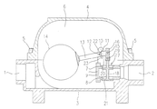
上記の技術的手段の具体例を示す実施例を説明する(図1と図2参照)。本発明のレバーフロート式ドレントラップは、入口1と出口2を有する本体3に蓋体4をボルト5で締結して内部に弁室6を有するケーシングを構成する。弁室6と出口2を連通する第1弁口7及び第2弁口8を有する弁座部材9を弁室6の下部の本体3に図示しないねじにより取り付ける。入口1は弁室6の下部に開口し、出口2は第1弁口7及び第2弁口8を介して弁室6の下部に開口する。
An embodiment showing a specific example of the above technical means will be described (see FIGS. 1 and 2). The lever float type drain trap of the present invention constitutes a casing having a
弁座部材9に図示しないねじにより取り付けた支持部材10の支持孔11に揺動軸12を回転可能に支持する。揺動軸12の回転に伴って回転するように揺動軸12にレバー13の右端部を嵌合して連結する。レバー13の左端に弁室6内の液位に応じて浮上降下する中空球形のフロート14を連結する。揺動軸12は断面三角形で三角形の一つの頂点をフロート14の中心に向けてレバー13に連結する。レバー13の右端に揺動軸12と平行な連結軸15を支持し、連結軸15に連結棒16の上部を回転可能に連結する。連結棒16の下部は弁体17の弁棒18の上端部に支持された揺動軸12と平行な弁軸19に回転可能に連結する。
The
弁体17は第1弁口7を下方の出口2側から開閉する第1弁体20と、第2弁口8を下方の弁室6側から開閉する第2弁体21と、第1弁体18と第2弁体19を連結する弁棒18とから構成する。第1弁体20及び第2弁体21が第1弁口7及び第2弁口8を閉じる位置からレバー13が更に閉弁方向に回転したときに揺動軸12上面が当接する上ストッパ面22を支持孔11に形成し、第1弁体20及び第2弁体21が第1弁口7及び第2弁口8を全開した位置から更にレバー13が閉弁方向に回転したときに揺動軸12下面が当接する下ストッパ面23を支持孔11に形成する。
The valve body 17 includes a
弁室6内の液位が低い場合は、図1に示すようにフロート14は降下し、第1弁体20及び第2弁体21が第1弁口7及び第2弁口8を閉じている。このとき、揺動軸12上面は支持孔11の上ストッパ面22に当接していない。配管系でウォータハンマ等が発生し弁室6内の圧力や液位が急激に変動してレバー13が更に閉弁方向に回転すると、フロート14が弁室6の底壁に当接する前に揺動軸12上面が支持孔11の上ストッパ面22に当接してフロート14の損傷を防止する。入口1から流入するドレンによって弁室6内の液位が上昇すると、フロート14が上動してレバー13が揺動軸12を中心に時計回り方向に回転する。このレバー13の回転により、連結棒16を介して弁体17が下動して第1弁体20及び第2弁体21が第1弁口7及び第2弁口8を開く。これにより、弁室6のドレンを出口2から排出する。図2に示すように第1弁体20及び第2弁体21が第1弁口7及び第2弁口8を全開した位置において、揺動軸12下面は支持孔11の下ストッパ面23に当接していない。配管系でウォータハンマ等が発生し弁室6内の圧力や液位が急激に変動してレバー13が更に開弁方向に回転すると、フロート14が弁室6の頂壁に当接する前に揺動軸12下面が支持孔11の下ストッパ面23に当接してフロート14の損傷を防止する。
When the liquid level in the
ドレンの排出により弁室6内の液位が低下すると、フロート14が下動してレバー13が揺動軸12を中心に反時計回り方向に回転する。このレバー13の回転により、連結棒16を介して弁体17が上動して第1弁体18及び第2弁体19が第1弁口7及び第2弁口8を閉じる。これにより、気体の漏出を防止する。
When the liquid level in the
1 入口
2 出口
3 本体
4 蓋体
6 弁室
7 第1弁口
8 第2弁口
10 支持部材
11 支持孔
12 揺動軸
13 レバー
14 フロート
17 弁体
20 第1弁体
21 第2弁体
22 上ストッパ面
23 下ストッパ面
DESCRIPTION OF SYMBOLS 1
Claims (1)
The casing forms an inlet, a valve chamber, and an outlet. A valve port that communicates the valve chamber and the outlet is formed in the lower portion of the valve chamber. The lever is pivotally supported by a support hole provided in the valve chamber. The float that rises and falls according to the liquid level in the valve chamber is connected to the lever, and the valve body that opens and closes the valve port is connected to the lever. One top point is connected to the lever toward the center of the float, and an upper stopper surface is formed in the support hole that contacts the upper surface of the swing shaft when the lever rotates further in the valve closing direction from the position where the valve body closes the valve port Lever float type drain trap.
Priority Applications (1)
| Application Number | Priority Date | Filing Date | Title |
|---|---|---|---|
| JP2007268243A JP5112809B2 (en) | 2007-10-15 | 2007-10-15 | Lever float drain trap |
Applications Claiming Priority (1)
| Application Number | Priority Date | Filing Date | Title |
|---|---|---|---|
| JP2007268243A JP5112809B2 (en) | 2007-10-15 | 2007-10-15 | Lever float drain trap |
Publications (2)
| Publication Number | Publication Date |
|---|---|
| JP2009097577A true JP2009097577A (en) | 2009-05-07 |
| JP5112809B2 JP5112809B2 (en) | 2013-01-09 |
Family
ID=40700769
Family Applications (1)
| Application Number | Title | Priority Date | Filing Date |
|---|---|---|---|
| JP2007268243A Expired - Fee Related JP5112809B2 (en) | 2007-10-15 | 2007-10-15 | Lever float drain trap |
Country Status (1)
| Country | Link |
|---|---|
| JP (1) | JP5112809B2 (en) |
Citations (4)
| Publication number | Priority date | Publication date | Assignee | Title |
|---|---|---|---|---|
| JPS4923925B1 (en) * | 1969-05-27 | 1974-06-19 | ||
| JPS55112488A (en) * | 1979-02-23 | 1980-08-30 | Tlv Co Ltd | Float type steam trap |
| JPH08114175A (en) * | 1994-10-14 | 1996-05-07 | Tlv Co Ltd | Liquid force feed device |
| JP2005036901A (en) * | 2003-07-15 | 2005-02-10 | Tlv Co Ltd | Float type drain trap |
-
2007
- 2007-10-15 JP JP2007268243A patent/JP5112809B2/en not_active Expired - Fee Related
Patent Citations (4)
| Publication number | Priority date | Publication date | Assignee | Title |
|---|---|---|---|---|
| JPS4923925B1 (en) * | 1969-05-27 | 1974-06-19 | ||
| JPS55112488A (en) * | 1979-02-23 | 1980-08-30 | Tlv Co Ltd | Float type steam trap |
| JPH08114175A (en) * | 1994-10-14 | 1996-05-07 | Tlv Co Ltd | Liquid force feed device |
| JP2005036901A (en) * | 2003-07-15 | 2005-02-10 | Tlv Co Ltd | Float type drain trap |
Also Published As
| Publication number | Publication date |
|---|---|
| JP5112809B2 (en) | 2013-01-09 |
Similar Documents
| Publication | Publication Date | Title |
|---|---|---|
| JP2008286238A (en) | Lever float type drain trap | |
| JP2008286239A (en) | Lever float type drain trap | |
| JP5917130B2 (en) | Lever float drain trap | |
| JP2009168087A (en) | Lever float type drain trap | |
| JP4980250B2 (en) | Lever float drain trap | |
| JP6086802B2 (en) | Lever float drain trap | |
| JP2009068634A (en) | Liquid pumping device | |
| JP5112810B2 (en) | Lever float drain trap | |
| JP5112809B2 (en) | Lever float drain trap | |
| JP5189026B2 (en) | Lever float drain trap | |
| JP4387718B2 (en) | Float type drain trap | |
| JP5112916B2 (en) | Lever float drain trap | |
| JP5524648B2 (en) | Lever float drain trap | |
| JP5456595B2 (en) | Lever float drain trap | |
| JP2011226503A (en) | Lever float type drain trap | |
| JP2010096252A (en) | Lever float type drain trap | |
| JP6118541B2 (en) | Float type drain trap | |
| JP6071496B2 (en) | Float type drain trap | |
| JP6416537B2 (en) | Float valve | |
| JP6077834B2 (en) | Float type drain trap | |
| JP2008020043A (en) | Force feeding device of liquid | |
| JP2012149663A (en) | Double seat valve | |
| JP2013024271A (en) | Lever float type drain trap | |
| JP2005061523A (en) | Exhaust valve | |
| JP6027791B2 (en) | Float type drain trap |
Legal Events
| Date | Code | Title | Description |
|---|---|---|---|
| A621 | Written request for application examination |
Free format text: JAPANESE INTERMEDIATE CODE: A621 Effective date: 20100825 |
|
| A977 | Report on retrieval |
Free format text: JAPANESE INTERMEDIATE CODE: A971007 Effective date: 20120213 |
|
| A131 | Notification of reasons for refusal |
Free format text: JAPANESE INTERMEDIATE CODE: A131 Effective date: 20120221 |
|
| A521 | Request for written amendment filed |
Free format text: JAPANESE INTERMEDIATE CODE: A523 Effective date: 20120420 |
|
| TRDD | Decision of grant or rejection written | ||
| A01 | Written decision to grant a patent or to grant a registration (utility model) |
Free format text: JAPANESE INTERMEDIATE CODE: A01 Effective date: 20121009 |
|
| A01 | Written decision to grant a patent or to grant a registration (utility model) |
Free format text: JAPANESE INTERMEDIATE CODE: A01 |
|
| A61 | First payment of annual fees (during grant procedure) |
Free format text: JAPANESE INTERMEDIATE CODE: A61 Effective date: 20121011 |
|
| FPAY | Renewal fee payment (event date is renewal date of database) |
Free format text: PAYMENT UNTIL: 20151019 Year of fee payment: 3 |
|
| R150 | Certificate of patent or registration of utility model |
Ref document number: 5112809 Country of ref document: JP Free format text: JAPANESE INTERMEDIATE CODE: R150 Free format text: JAPANESE INTERMEDIATE CODE: R150 |
|
| LAPS | Cancellation because of no payment of annual fees |