JP2009097567A - Pressure sensor integrated type electromagnetic valve and brake-fluid pressure control device using the same - Google Patents
Pressure sensor integrated type electromagnetic valve and brake-fluid pressure control device using the same Download PDFInfo
- Publication number
- JP2009097567A JP2009097567A JP2007267838A JP2007267838A JP2009097567A JP 2009097567 A JP2009097567 A JP 2009097567A JP 2007267838 A JP2007267838 A JP 2007267838A JP 2007267838 A JP2007267838 A JP 2007267838A JP 2009097567 A JP2009097567 A JP 2009097567A
- Authority
- JP
- Japan
- Prior art keywords
- pressure sensor
- terminal
- solenoid valve
- coil
- pressure
- Prior art date
- Legal status (The legal status is an assumption and is not a legal conclusion. Google has not performed a legal analysis and makes no representation as to the accuracy of the status listed.)
- Granted
Links
Images


Abstract
Description
この発明は、液圧の制御に利用される圧力センサ一体型電磁弁とそれを用いた車両用のブレーキ液圧制御装置に関する。 The present invention relates to a pressure sensor integrated electromagnetic valve used for controlling hydraulic pressure and a brake hydraulic pressure control device for a vehicle using the same.
例えば、電子制御機能を備えた車両用のブレーキ液圧制御装置は、液圧ユニットのハウジングに電子制御ユニットを組み付けて構成される。液圧ユニットのハウジングには液圧回路が設けられ、さらに、その液圧回路内の液圧を制御する電磁弁が組み付けられている。その電磁弁の中に、下記特許文献1に開示されるようなもの、すなわち、回路内液圧を検出する圧力センサを一体化して設けたものがある。この電磁弁は、磁性体で形成されたコア(ステータコア)に流体通路を設け、さらに、このコアの端部(電磁弁の可動子に対面する側とは反対側の端部)に圧力センサを取り付け、前記流体通路を通して導入される回路内ブレーキ液の液圧を前記圧力センサで検出する構造になっている。
For example, a brake hydraulic pressure control device for a vehicle having an electronic control function is configured by assembling an electronic control unit in a housing of a hydraulic pressure unit. A hydraulic circuit is provided in the housing of the hydraulic unit, and an electromagnetic valve for controlling the hydraulic pressure in the hydraulic circuit is further assembled. Among the solenoid valves, there is a solenoid valve disclosed in
一方、電子制御ユニットは、制御回路を設けた回路基板をケースに収納して構成されている。前記電磁弁はこの電子制御ユニットのケースによって覆われ、前記回路基板内の電気回路と前記圧力センサとの電気的導通が圧力センサと回路基板との間でなされている。なお、前記特許文献1は、圧力センサから電磁弁の軸方向に延びだしたセンサ端子(接触子)を圧力センサの上部に配置したセンサ保持部で保持する構造を図3に開示している。
前掲の特許文献1の図3の構造は、圧力センサを電磁弁に一体化しているため圧力制御装置の小型化が図れ、また、センサ端子をセンサ保持部で保持することで圧力センサの電気接続を安定させることもできる。ところが、同文献の図3の構造は、センサ保持部が圧力センサの上部に配置されているため、圧力制御装置の電磁弁軸方向寸法(以下では単に軸方向寸法と言う)がセンサ保持部の設置スペース相当分長くなって同装置の更なる小型化が図り難い。
The structure shown in FIG. 3 of the above-mentioned
車両用のブレーキ液圧制御装置は、車両の更なる軽量化やエンジンルーム内スペースの更なる有効利用などのためにより一層小型化することが望まれている。その要求に応えるためには、同装置の軸方向寸法をこれまで以上に短縮することが不可欠である。 It is desired to further reduce the size of the brake hydraulic pressure control device for a vehicle in order to further reduce the weight of the vehicle and further effectively use the space in the engine room. In order to meet the demand, it is essential to shorten the axial dimension of the apparatus more than ever.
この発明は、圧力センサ一体型電磁弁やそれを用いたブレーキ液圧制御装置の更なる小型化を可能となすために、その電磁弁やそれを用いたブレーキ液圧制御装置の軸方向寸法を電気接続の安定性を確保しながら短くすることを課題としている。 In order to enable further miniaturization of a pressure sensor integrated solenoid valve and a brake fluid pressure control device using the pressure sensor, the axial dimension of the solenoid valve and the brake fluid pressure control device using the solenoid valve can be reduced. The problem is to shorten the electrical connection while ensuring stability.
上記の課題を解決するため、この発明においては、弁体駆動用の磁力を発生させるコイルの内側に磁性体のコアを有し、そのコアの端部に圧力センサが固定して取り付けられ、前記コアに設けられた流体通路に液圧回路内の液体が導入され、その液体の圧力を前記圧力センサで検出するように構成された圧力センサ一体型電磁弁において、
センサ端子と、このセンサ端子を保持する端子保持部とを有し、前記端子保持部が前記コイルの径方向において前記圧力センサの外側に配置され、前記センサ端子が接続導体を介して前記圧力センサに電気的に接続される構造にした。
In order to solve the above problems, in the present invention, a magnetic core is provided inside a coil for generating a magnetic force for driving a valve body, and a pressure sensor is fixedly attached to an end of the core. In a pressure sensor-integrated solenoid valve configured to detect a pressure of the liquid in the fluid passage provided in the core, and the pressure of the liquid is detected by the pressure sensor.
A sensor terminal and a terminal holding part for holding the sensor terminal, wherein the terminal holding part is disposed outside the pressure sensor in a radial direction of the coil, and the sensor terminal is connected to the pressure sensor via a connection conductor. The structure is electrically connected to.
この圧力センサ一体型電磁弁の、好ましい形態を以下に列挙する。
(1)前記端子保持部が前記コイルにおけるその軸方向を臨む端面に配置されているもの。(2)前記端子保持部が前記コアの外周、又は電磁弁のヨークに設けた延長筒部の内周に圧入して固定されているもの。
(3)前記センサ端子が前記端子保持部に前記コイルの軸方向に延びて保持されているもの。
(4)前記コイルを電源に接続するコイル端子を有し、そのコイル端子が前記端子保持部を貫通して同端子保持部に保持されているもの。
(5)前記接続導体が前記圧力センサに形成された電極に弾性的に押し付けられて前記圧力センサと前記センサ端子との間の電気導通が確保されているもの。この形態での前記接続導体の押し付けは、電磁弁の軸と平行方向に向けてなされる構造と電磁弁の径方向に向けてなされる構造の2通りが考えられる。
(6)前記接続導体がボンディングワイヤであり、前記圧力センサと前記センサ端子との電気接続がそのボンディングワイヤを介してなされているもの。
(7)前記圧力センサが前記コイルよりも同コイルの軸方向に突出して設けられているもの。
Preferred forms of this pressure sensor integrated solenoid valve are listed below.
(1) The terminal holding portion is disposed on an end face of the coil facing the axial direction. (2) The terminal holding portion is fixed by being press-fitted into the outer periphery of the core or the inner periphery of the extension tube portion provided in the yoke of the electromagnetic valve.
(3) The sensor terminal is held by the terminal holding portion extending in the axial direction of the coil.
(4) A coil terminal that connects the coil to a power source, and the coil terminal penetrates the terminal holding part and is held by the terminal holding part.
(5) The connection conductor is elastically pressed against an electrode formed on the pressure sensor to ensure electrical continuity between the pressure sensor and the sensor terminal. The connection conductor can be pressed in this form in two ways: a structure formed in a direction parallel to the axis of the electromagnetic valve and a structure formed in the radial direction of the electromagnetic valve.
(6) The connection conductor is a bonding wire, and the pressure sensor and the sensor terminal are electrically connected through the bonding wire.
(7) The pressure sensor is provided so as to protrude in the axial direction of the coil from the coil.
上述した圧力センサ一体型電磁弁は、例えば、自動車用のブレーキ液圧制御装置に利用する。そのブレーキ液圧制御装置は、ハウジングの内部に液圧回路が設けられた液圧ユニットを有し、その液圧ユニットの前記ハウジングの一面側に前記液圧回路の液圧を制御する電磁弁が組み付けられ、その電磁弁の中の少なくとも一つがこの発明の圧力センサ一体型電磁弁で構成され、さらに、ケースの内部に回路基板を収納して構成される電子制御ユニットが、前記ハウジングの一面側に取り付けられ、前記圧力センサ一体型電磁弁が前記ケースに覆われ、前記端子保持部が前記回路基板と前記コイルとの間に配置されてこの端子保持部で保持した前記センサ端子が前記回路基板上の電気回路に電気的に接続されたものとなす。 The above-described pressure sensor integrated solenoid valve is used, for example, in a brake fluid pressure control device for automobiles. The brake fluid pressure control device has a fluid pressure unit provided with a fluid pressure circuit inside a housing, and an electromagnetic valve for controlling the fluid pressure of the fluid pressure circuit is provided on one surface side of the housing of the fluid pressure unit. At least one of the solenoid valves is assembled with the pressure sensor integrated solenoid valve of the present invention, and an electronic control unit configured by housing a circuit board inside the case is provided on one side of the housing. The pressure sensor integrated solenoid valve is covered by the case, the terminal holding part is disposed between the circuit board and the coil, and the sensor terminal held by the terminal holding part is the circuit board. It shall be electrically connected to the above electrical circuit.
この発明は、かかるブレーキ液圧制御装置も併せて提供する。なお、この装置は、前記端子保持部がケースと一体に形成されて前記圧力センサ一体型電磁弁と前記回路基板との間に配置されているものであってもよい。また、前記電磁弁のコイルが、前記電子制御ユニットとの接続状態を維持して電磁弁のコア及び弁ハウジングから分離可能とされるものも好ましい形態として考えられる。 The present invention also provides such a brake fluid pressure control device. In this device, the terminal holding portion may be formed integrally with the case and disposed between the pressure sensor integrated electromagnetic valve and the circuit board. In addition, a configuration in which the coil of the solenoid valve is separable from the core and the valve housing of the solenoid valve while maintaining a connection state with the electronic control unit is also considered as a preferable mode.
この発明の圧力センサ一体型電磁弁は、端子保持部をコイルの径方向において圧力センサの外側に配置したので、前掲の特許文献1が圧力センサの上方に確保していたセンサ保持部挿入用のスペースが不要であり、その分、軸方向寸法を短縮することができる。そのために、当該電磁弁を採用したブレーキ液圧制御装置の軸方向寸法も短縮することが可能になる。
In the pressure sensor integrated solenoid valve according to the present invention, since the terminal holding portion is arranged outside the pressure sensor in the radial direction of the coil, the above-mentioned
センサ端子と圧力センサの電気接続は接続導体を設けて行っており、このことによって端子保持部を圧力センサの側面の周囲に配置することが可能になっている。 Electrical connection between the sensor terminal and the pressure sensor is performed by providing a connection conductor, which makes it possible to arrange the terminal holding portion around the side surface of the pressure sensor.
なお、端子保持部をコイルにおけるその軸方向を臨む端面に配置した電磁弁は、端子保持部の設置スペースが径方向に広がらず、さらなる小型化が図れる。 In addition, the solenoid valve which arrange | positioned the terminal holding part in the end surface which faces the axial direction in a coil does not spread the installation space of a terminal holding part to radial direction, and can achieve further size reduction.
また、端子保持部をコアの外周やヨークの延長筒部の内周に圧入して固定した電磁弁は、接続導体を接続相手に接触導通させる構造を採用したときに、振動等に起因した接続導体の接触不良を防ぐ効果が得られる。 In addition, the solenoid valve with the terminal holding part pressed into and fixed to the outer periphery of the core or the inner periphery of the extension cylinder part of the yoke is connected due to vibrations etc. The effect which prevents the poor contact of a conductor is acquired.
さらに、センサ端子やコイル端子が端子保持部に保持されているものは、端子保持部による各端子や接続導体の位置決めが可能になる。 Further, when the sensor terminal and the coil terminal are held by the terminal holding part, the terminals and connecting conductors can be positioned by the terminal holding part.
接続導体がセンサの電極に弾性的に押し付けられて電気導通が確保されているものは、これらの接触導通部の導体接触面に圧力が加わって導通状態が安定する。また、コイルを電磁弁のコア及び弁ハウジングから一旦分離して再度組み付けるときの接触導通部の切り離し、再接続も簡単である。 When the connection conductor is elastically pressed against the electrode of the sensor to ensure electrical conduction, pressure is applied to the conductor contact surfaces of these contact conduction portions, and the conduction state is stabilized. In addition, when the coil is once separated from the core of the solenoid valve and the valve housing and reassembled, the contact conducting portion is easily disconnected and reconnected.
このほか、圧力センサとセンサ端子との電気接続がボンディングワイヤを介してなされるようにすることも可能である。 In addition, the electrical connection between the pressure sensor and the sensor terminal can be made through a bonding wire.
また、圧力センサはコイルからの磁気的影響を回避するためにコイルよりもその軸方向に突出させて設けるようにしてもよく、この構造のものは、コイル軸方向側にできるスペースを端子保持部の設置スペースとして有効に活用することができ、無駄なスペースが減少して小型化の効果が高まる。 Further, the pressure sensor may be provided so as to protrude in the axial direction of the coil in order to avoid magnetic influence from the coil. It can be effectively used as an installation space, reducing wasted space and increasing the effect of miniaturization.
この発明のブレーキ液圧制御装置も、上記電磁弁の使用によって小型化が図れる。また、電磁弁に設ける端子保持部が電子制御ユニットのケースに一体化されている装置は、部品数の削減や組み付け性の改善も図れる。 The brake fluid pressure control device of the present invention can also be reduced in size by using the electromagnetic valve. In addition, the device in which the terminal holding portion provided in the electromagnetic valve is integrated with the case of the electronic control unit can reduce the number of components and improve the assembling property.
さらに、電磁弁のコイルが、電子制御ユニットとの接続状態を維持して電磁弁のコア及び弁ハウジングから分離可能とされているブレーキ液圧制御装置は、コイルを電子制御ユニットに組み付けた後、これらをハウジングに組み付けることができ、組み立ての手順に自由度が生じる。そのため、市場で電子制御ユニットを液圧ユニットのハウジングから外して部品の交換などを行うときの対応も容易になる。 Furthermore, the brake hydraulic pressure control device in which the coil of the electromagnetic valve maintains the connection state with the electronic control unit and can be separated from the core of the electromagnetic valve and the valve housing is, after the coil is assembled to the electronic control unit, These can be assembled to the housing, and the assembly procedure is free. Therefore, it becomes easy to deal with the case where the electronic control unit is removed from the housing of the hydraulic unit and parts are exchanged in the market.
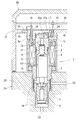
以下、添付図面の図1〜図8に基づいてこの発明の実施の形態を説明する。図1は、圧力センサ一体型電磁弁の第1の実施形態である。この図1の圧力センサ一体型電磁弁1は、弁ハウジング2と、その弁ハウジング2の内部に組み込んだ弁体3と、その弁体と組み合わせて弁部を構成する弁座4と、弁体3を保持した可動子(アーマチュア)5と、その可動子5を閉弁方向に付勢する復帰スプリング6と、弁ハウジング2の後部に気密封止がなされるように連結した磁性体のコア7と、そのコア7の周囲に配置されるコイル8と、そのコイル8を覆う磁性体のヨーク9と、コア7の端部に固定して取り付けられる圧力センサ10と、この発明を特徴づける端子保持部11を組み合わせて構成されている。図示の電磁弁1は、コイル8が発生させる磁力を駆動力にして可動子5が復帰スプリング6の力に抗して図中上方に引き動かされ、弁体3が弁座4から離反して弁部を境にした液圧回路23の上流側と下流側が連通する。
Embodiments of the present invention will be described below with reference to FIGS. FIG. 1 shows a first embodiment of a pressure sensor integrated solenoid valve. 1 includes a
液圧回路23は、液圧ユニットのハウジング22に設けられており、この液圧回路23に導入される液体の圧力が電磁弁1によって制御される。コア7の内部には流体通路12が設けられている。その流体通路12は、可動子5に設けられた連絡路13を介して弁ハウジング2の内部に形成された液室14に連通しており、液圧回路23内の液体が流体通路12に導入される。圧力センサ10はコア7の端部に接合されており、流体通路12に導入した液圧で流体通路12の終端に配置されたコア7の薄肉部7aを弾性変形させて歪ませ、そのときの歪量を圧力センサ10で検出して液圧回路23内の液圧を測定する構造になっている。なお、例示の電磁弁での圧力検出は薄肉部7aを介して間接的になされるが、前掲の特許文献1が開示しているように、圧力通路を貫通させ、液圧回路内の液体を圧力センサの一面に直接触れさせて圧力検出を行うこともできる。
The
コア7の圧力センサ10を固定した部分は、コイル8よりもその軸方向(図1においては上方)に突出しており、その突出部の周囲、かつ、コイル8の端面8a上に端子保持部11が配置されている。この端子保持部11は絶縁性を有する樹脂などで形成されており、コア7によってコイル径方向に動き止めされるようにコア7の外周に圧入するなどして嵌められている。
The portion of the
図1の15は、圧力センサ10を回路基板32上に形成された電気回路に接続するセンサ端子である。このセンサ端子15は、電磁弁の軸心と平行方向に延びる向きにして設けられ、一部分が端子保持部11に植え込まれ、位置決めされた状態で端子保持部11に保持されている。
図1の16は、コイル8を電源に接続するコイル端子である。このコイル端子16も電磁弁の軸心と平行方向に延びる向きにして設けられている。そのコイル端子16は端子保持部11を貫通しており、センサ端子15と同様に、端子保持部11に位置決めされて保持される。
図1の17は、センサ端子15につながれた接続導体である。図1の接続導体17は、端子保持部11の内径面から内側に張り出している。張り出し部17aは、ばね弾性を付与しており、端子保持部11の組み付け状態(図1の状態)でその張り出し部17aが弾性変形して電磁弁軸方向の弾性復元力を生じ、その力で張り出し部17aが圧力センサ10の上面に形成された電極10aに圧力をもって押し付けられて電極10aと接続導体17との間に接触導通部が形成されるようになっている。
端子保持部11とコイル8は、回路基板32を内蔵したケース31と一緒に電磁弁のコア7及び弁ハウジング2から取り外せるようにしており、このために、完全に組み立てた電磁弁をハウジング22に組み付け、その後に端子保持部11の装着、電子制御ユニットの組み付けを行う手順のほかに、端子保持部11とコイル8を予めケース31側に組み付け、ケース31を液圧ユニットのハウジング22に組み付けるときにそのコイル8をハウジング22に取り付けられている電磁弁のコア7及び弁ハウジング2の外周に挿入し、その後にコイル端子16を回路導体33に接続する組み立て手順を採用することも可能になり、組み立ての自由度が高まっている。また、コア7及び弁ハウジング2からのコイル8の分離、再装着を接続導体の切断、再連結なしで行うことができ、市場で電子制御ユニットを液圧ユニットのハウジングから外して部品の交換などを行うときの対応も容易になる。
The
図1の構造は、端子保持部11をコア7の外周に嵌め、端子保持部11に設けた貫通孔18をガイドにしてその貫通孔18にコイル端子16を挿入する。その作業で電極10aと接続導体17が相互接続点に位置決めされるため、組み付け性に優れる。
In the structure of FIG. 1, the
図1の19はフィルタ、31は電子制御ユニットのケース、33は電源に接続される回路導体である。バスバーで形成されたこの回路導体33はケース31にモールドして設けられており、この回路導体33にコイル端子16が溶接するなどして接続される。センサ端子15とコイル端子16は、図1に示すように、ケース31に設けたガイド孔34(これは必須ではない)でガイドしてケース31内に挿入すると回路基板32及び回路導体33との位置合わせがなされて端子の接続作業がしやすい。
In FIG. 1, 19 is a filter, 31 is a case of an electronic control unit, and 33 is a circuit conductor connected to a power source. The
なお、端子保持部11は、図2に示すように、ヨーク9に延長筒部9aを設け、その延長筒部9aの内側に端子保持部11を圧入等で挿入してヨーク9で保持することもできる。また、図3に示すように、ケース31と一体に形成してケース31で保持することもできる。
As shown in FIG. 2, the
図4、図5に、この発明の電磁弁の第2の実施形態を示す。この第2の実施形態の圧力センサ一体型電磁弁1は、ばね弾性を有する接続導体17を端子保持部11の内径側に配置し、センサ端子15に接続したその接続導体17を圧力センサ10の外周に設けた電極10aに圧接させる構造にしたものである。接続導体17は、電極10aに対して電磁弁の径方向に押し付けられる。この構造は、コア7と端子保持部11の軸方向への相対変位が接続導体17と電極10aの相対スライドによって許容されるため、コア7と端子保持部11が線膨張係数の異なる材料で形成されていても環境温度が変化したときの接触導通部の面圧(電極10aに対する接続導体17の押し付け圧)変動が起こり難く、接触導通部の導通状態が安定する。その他の構成は図1の電磁弁と同じであるので、図1と同一部分の図と同一要素に関する説明は省く。
4 and 5 show a second embodiment of the electromagnetic valve of the present invention. In the pressure sensor integrated
図6に、この発明の電磁弁の第3の実施形態を示す。この第3の実施形態の圧力センサ一体型電磁弁1は、接続導体17として図1の接触導通方式の接続導体に代えてボンディングワイヤを採用し、圧力センサ10とセンサ端子15との間の電気接続をそのボンディングワイヤで行ったものである。その他の構成は図1の電磁弁と同じであるので、同一要素に同一符号を付して説明を省く。端子保持部11が圧力センサ10の周囲に配置されているので、図示のボンディングワイヤによる接続も支障なく実施することができる。
FIG. 6 shows a third embodiment of the solenoid valve of the present invention. In the pressure sensor integrated
この図6の圧力センサ一体型電磁弁1は、接続導体17としてボンディングワイヤを用いているので、市場でコイルを電磁弁のコア及び弁ハウジングから分離することが要求される用途には適していないが、電気接続の安定性に優れる。
The pressure sensor integrated
図7は、車両に搭載される電子制御機能を備えたブレーキ液圧制御装置の一例を表している。このブレーキ液圧制御装置20は、液圧ユニット21と電子制御ユニット30を組み合わせて構成されている。液圧ユニット21は、ハウジング22の内部に、液圧回路23、ポンプ24、マスタシリンダに接続されるポート25、車両のホイールシリンダに接続されるポート26を設けたもの(必要に応じてリザーバ27なども設けられる)であって、ハウジング22の外部にポンプ24を駆動するモータ28が取り付けられている。また、ハウジング22の一面側にポート25,26の接続状態、ポンプ24とポート26の接続状態、ポート26とリザーバ27の接続状態を切り替える電磁弁Vが組み付けられている。電磁弁Vは複数個設けられる。その電磁弁は、弁部の開度を変化させてポート26内の液圧を調節する機能をもつものが採用されることもある。その中の少なくとも一つがこの発明の圧力センサ一体型電磁弁で構成されている。
FIG. 7 shows an example of a brake fluid pressure control device having an electronic control function mounted on a vehicle. The brake fluid
電子制御ユニット30は、制御回路を有する回路基板32をケース31に収納して構成されており、この電子制御ユニット30が液圧ユニット21のハウジング22の一面側に取り付けられて各電磁弁Vがケース31に覆われる。例示のブレーキ液圧制御装置20は、図8に示すように、端子保持部11が回路基板32とコイル8との間に配置され、この端子保持部11で保持したセンサ端子15がケース31に設けたガイド孔34に挿通されて回路基板32上の電気回路に電気的に接続される。また、コイル端子16もケース31に設けたガイド孔34に挿通されて回路導体33に接続される。回路基板32には各種センサ(これには電磁弁に一体化された圧力センサも含まれる)からの情報に基づいてホイールシリンダ圧の調圧の必要性を判断し、調圧が必要と判断したときに電磁弁に調圧指令を出すECU(電子制御装置)が搭載されており(図示せず)、そのECUからの指令に基づいて電磁弁Vが作動して液圧回路23内のブレーキ液圧を制御する。
The
なお、例示のブレーキ液圧制御装置20に採用する圧力センサ一体型電磁弁は、電子制御ユニット30とともに電磁弁のコイル8を分離できるもの、できないものを問わない。
In addition, the pressure sensor integrated solenoid valve employed in the illustrated brake fluid
1 圧力センサ一体型電磁弁
2 弁ハウジング
3 弁体
4 弁座
5 可動子(アーマチュア)
6 復帰スプリング
7 コア
7a 薄肉部
8 コイル
8a 端面
9 ヨーク
9a 延長筒部
10 圧力センサ
10a 電極
11 端子保持部
12 流体通路
13 連絡路
14 液室
15 センサ端子
16 コイル端子
17 接続導体
17a 張り出し部
18 貫通孔
19 フィルタ
20 ブレーキ液圧制御装置
21 液圧ユニット
22 ハウジング
23 液圧回路
24 ポンプ
25、26 ポート
27 リザーバ
28 モータ
30 電子制御ユニット
31 ケース
32 回路基板
33 回路導体
34 ガイド孔
V 電磁弁
DESCRIPTION OF
6
Claims (11)
センサ端子(15)と、このセンサ端子(15)を保持する端子保持部(11)とを有し、前記端子保持部(11)が前記コイルの径方向において前記圧力センサ(10)の外側に配置され、前記センサ端子(15)が接続導体(17)を介して前記圧力センサ(10)に電気的に接続されていることを特徴とする圧力センサ一体型電磁弁。 A magnetic core (7) is provided inside a coil (8) for generating a magnetic force, and a pressure sensor (10) is fixedly attached to an end of the core (7) and provided on the core (7). A pressure sensor-integrated solenoid valve configured to detect the pressure of the liquid by introducing the liquid in the hydraulic circuit (23) into the fluid passage (12) and detecting the pressure of the liquid with the pressure sensor (10);
It has a sensor terminal (15) and a terminal holding part (11) for holding the sensor terminal (15), and the terminal holding part (11) is outside the pressure sensor (10) in the radial direction of the coil. The pressure sensor integrated solenoid valve, wherein the solenoid terminal is disposed and the sensor terminal (15) is electrically connected to the pressure sensor (10) via a connection conductor (17).
Priority Applications (1)
| Application Number | Priority Date | Filing Date | Title |
|---|---|---|---|
| JP2007267838A JP5104186B2 (en) | 2007-10-15 | 2007-10-15 | Pressure sensor integrated solenoid valve and brake fluid pressure control device using the same |
Applications Claiming Priority (1)
| Application Number | Priority Date | Filing Date | Title |
|---|---|---|---|
| JP2007267838A JP5104186B2 (en) | 2007-10-15 | 2007-10-15 | Pressure sensor integrated solenoid valve and brake fluid pressure control device using the same |
Publications (2)
| Publication Number | Publication Date |
|---|---|
| JP2009097567A true JP2009097567A (en) | 2009-05-07 |
| JP5104186B2 JP5104186B2 (en) | 2012-12-19 |
Family
ID=40700762
Family Applications (1)
| Application Number | Title | Priority Date | Filing Date |
|---|---|---|---|
| JP2007267838A Expired - Fee Related JP5104186B2 (en) | 2007-10-15 | 2007-10-15 | Pressure sensor integrated solenoid valve and brake fluid pressure control device using the same |
Country Status (1)
| Country | Link |
|---|---|
| JP (1) | JP5104186B2 (en) |
Cited By (2)
| Publication number | Priority date | Publication date | Assignee | Title |
|---|---|---|---|---|
| JP2012162118A (en) * | 2011-02-04 | 2012-08-30 | Hitachi Automotive Systems Ltd | Brake device |
| JP2021092321A (en) * | 2015-04-28 | 2021-06-17 | パーカー・ハニフィン・コーポレーション | Low profile miniature solenoid proportional valve |
Citations (11)
| Publication number | Priority date | Publication date | Assignee | Title |
|---|---|---|---|---|
| JPS63252228A (en) * | 1987-04-09 | 1988-10-19 | Nippon Denso Co Ltd | Semiconductor pressure detector |
| JPH05340962A (en) * | 1992-06-10 | 1993-12-24 | Omron Corp | Capacitive acceleration sensor |
| JPH08122179A (en) * | 1994-10-24 | 1996-05-17 | Matsushita Electric Works Ltd | Semiconductor pressure sensor and its production |
| JP2000036408A (en) * | 1998-07-07 | 2000-02-02 | Fasco Controls Corp | Solenoid pressure converter |
| JP2002520211A (en) * | 1998-07-08 | 2002-07-09 | コンティネンタル・テーベス・アクチエンゲゼルシヤフト・ウント・コンパニー・オッフェネ・ハンデルスゲゼルシヤフト | Brake pressure control device |
| JP2003522677A (en) * | 2000-02-18 | 2003-07-29 | コンチネンタル・テベス・アーゲー・ウント・コンパニー・オーハーゲー | Pressure control device |
| JP2004090847A (en) * | 2002-09-03 | 2004-03-25 | Mitsubishi Electric Corp | Vehicular pressure control device |
| JP2005282680A (en) * | 2004-03-29 | 2005-10-13 | Nissin Kogyo Co Ltd | Vehicular brake liquid pressure control device |
| JP2005280444A (en) * | 2004-03-29 | 2005-10-13 | Nissin Kogyo Co Ltd | Brake hydraulic control device for vehicle |
| JP2005351409A (en) * | 2004-06-11 | 2005-12-22 | Advics:Kk | Solenoid valve and method for assembling the same |
| JP2006083886A (en) * | 2004-09-14 | 2006-03-30 | Denso Corp | Mounting structure for solenoid valve integrated type pressure sensor |
-
2007
- 2007-10-15 JP JP2007267838A patent/JP5104186B2/en not_active Expired - Fee Related
Patent Citations (11)
| Publication number | Priority date | Publication date | Assignee | Title |
|---|---|---|---|---|
| JPS63252228A (en) * | 1987-04-09 | 1988-10-19 | Nippon Denso Co Ltd | Semiconductor pressure detector |
| JPH05340962A (en) * | 1992-06-10 | 1993-12-24 | Omron Corp | Capacitive acceleration sensor |
| JPH08122179A (en) * | 1994-10-24 | 1996-05-17 | Matsushita Electric Works Ltd | Semiconductor pressure sensor and its production |
| JP2000036408A (en) * | 1998-07-07 | 2000-02-02 | Fasco Controls Corp | Solenoid pressure converter |
| JP2002520211A (en) * | 1998-07-08 | 2002-07-09 | コンティネンタル・テーベス・アクチエンゲゼルシヤフト・ウント・コンパニー・オッフェネ・ハンデルスゲゼルシヤフト | Brake pressure control device |
| JP2003522677A (en) * | 2000-02-18 | 2003-07-29 | コンチネンタル・テベス・アーゲー・ウント・コンパニー・オーハーゲー | Pressure control device |
| JP2004090847A (en) * | 2002-09-03 | 2004-03-25 | Mitsubishi Electric Corp | Vehicular pressure control device |
| JP2005282680A (en) * | 2004-03-29 | 2005-10-13 | Nissin Kogyo Co Ltd | Vehicular brake liquid pressure control device |
| JP2005280444A (en) * | 2004-03-29 | 2005-10-13 | Nissin Kogyo Co Ltd | Brake hydraulic control device for vehicle |
| JP2005351409A (en) * | 2004-06-11 | 2005-12-22 | Advics:Kk | Solenoid valve and method for assembling the same |
| JP2006083886A (en) * | 2004-09-14 | 2006-03-30 | Denso Corp | Mounting structure for solenoid valve integrated type pressure sensor |
Cited By (2)
| Publication number | Priority date | Publication date | Assignee | Title |
|---|---|---|---|---|
| JP2012162118A (en) * | 2011-02-04 | 2012-08-30 | Hitachi Automotive Systems Ltd | Brake device |
| JP2021092321A (en) * | 2015-04-28 | 2021-06-17 | パーカー・ハニフィン・コーポレーション | Low profile miniature solenoid proportional valve |
Also Published As
| Publication number | Publication date |
|---|---|
| JP5104186B2 (en) | 2012-12-19 |
Similar Documents
| Publication | Publication Date | Title |
|---|---|---|
| JP5678011B2 (en) | Connection unit for pressure measuring cell | |
| JP2015107749A (en) | Input device for brake system and vehicle brake system | |
| CN110383402B (en) | Electric component assembly and vehicle brake hydraulic pressure control device | |
| CN110383401B (en) | Coil assembly and brake control device | |
| JP6024622B2 (en) | Brake hydraulic pressure control device | |
| JP5104186B2 (en) | Pressure sensor integrated solenoid valve and brake fluid pressure control device using the same | |
| CN110447314A (en) | Electric components assembly and hydraulic brake controlling device for vehicle | |
| JP4978455B2 (en) | Press-fit terminal and hydraulic pressure control device using the same | |
| JP6056238B2 (en) | Electrical connection structure between circuit board and electrical components | |
| JP2009030801A (en) | Fluid control device and method of manufacturing the same | |
| JP2010014476A (en) | Contact probe, pressure sensor, and brake hydraulic pressure control device for vehicle | |
| CN108778867B (en) | Electronic control device | |
| JP4705415B2 (en) | Electric motor | |
| JP5584061B2 (en) | Brake fluid pressure control unit | |
| JP3653260B2 (en) | Vehicle pressure control device | |
| CN110382314A (en) | Electric components assembly and hydraulic brake controlling device for vehicle | |
| JP2008185334A (en) | Pressure sensor | |
| JP2012056391A5 (en) | ||
| JP2005280444A (en) | Brake hydraulic control device for vehicle | |
| JP5281608B2 (en) | Electronic control unit and vehicle brake hydraulic pressure control device | |
| JP2012240640A (en) | Actuator for hydraulic pressure control of brake | |
| US10551268B2 (en) | Pressure sensor with lengthily disposed substrate | |
| JPWO2018105259A1 (en) | Pressure detection device | |
| KR101268472B1 (en) | Modulate block | |
| KR20240042856A (en) | Apparatus for sensing displacement of brake pedal |
Legal Events
| Date | Code | Title | Description |
|---|---|---|---|
| A621 | Written request for application examination |
Free format text: JAPANESE INTERMEDIATE CODE: A621 Effective date: 20100909 |
|
| A977 | Report on retrieval |
Free format text: JAPANESE INTERMEDIATE CODE: A971007 Effective date: 20120210 |
|
| A131 | Notification of reasons for refusal |
Free format text: JAPANESE INTERMEDIATE CODE: A131 Effective date: 20120228 |
|
| A521 | Written amendment |
Free format text: JAPANESE INTERMEDIATE CODE: A523 Effective date: 20120418 |
|
| TRDD | Decision of grant or rejection written | ||
| A01 | Written decision to grant a patent or to grant a registration (utility model) |
Free format text: JAPANESE INTERMEDIATE CODE: A01 Effective date: 20120904 |
|
| A01 | Written decision to grant a patent or to grant a registration (utility model) |
Free format text: JAPANESE INTERMEDIATE CODE: A01 |
|
| A61 | First payment of annual fees (during grant procedure) |
Free format text: JAPANESE INTERMEDIATE CODE: A61 Effective date: 20120917 |
|
| R150 | Certificate of patent or registration of utility model |
Free format text: JAPANESE INTERMEDIATE CODE: R150 |
|
| FPAY | Renewal fee payment (event date is renewal date of database) |
Free format text: PAYMENT UNTIL: 20151012 Year of fee payment: 3 |
|
| LAPS | Cancellation because of no payment of annual fees |