JP2009092993A - Display filter and display module having display filter - Google Patents

Display filter and display module having display filter Download PDF

Info

Publication number
JP2009092993A
JP2009092993A JP2007264375A JP2007264375A JP2009092993A JP 2009092993 A JP2009092993 A JP 2009092993A JP 2007264375 A JP2007264375 A JP 2007264375A JP 2007264375 A JP2007264375 A JP 2007264375A JP 2009092993 A JP2009092993 A JP 2009092993A
Authority
JP
Japan
Prior art keywords
filter
design pattern
light
light source
display
Prior art date
Legal status (The legal status is an assumption and is not a legal conclusion. Google has not performed a legal analysis and makes no representation as to the accuracy of the status listed.)
Pending
Application number
JP2007264375A
Other languages
Japanese (ja)
Inventor
Atsumasa Fujii
淳将 藤井
Hideki Nakajo
秀樹 中條
Soichi Matsushita
壮一 松下
Current Assignee (The listed assignees may be inaccurate. Google has not performed a legal analysis and makes no representation or warranty as to the accuracy of the list.)
Omron Corp
Original Assignee
Omron Corp
Omron Tateisi Electronics Co
Priority date (The priority date is an assumption and is not a legal conclusion. Google has not performed a legal analysis and makes no representation as to the accuracy of the date listed.)
Filing date
Publication date
Application filed by Omron Corp, Omron Tateisi Electronics Co filed Critical Omron Corp
Priority to JP2007264375A priority Critical patent/JP2009092993A/en
Priority to KR1020080076237A priority patent/KR100989240B1/en
Priority to US12/246,698 priority patent/US20090097145A1/en
Publication of JP2009092993A publication Critical patent/JP2009092993A/en
Pending legal-status Critical Current

Links

Images

Classifications

    • GPHYSICS
    • G02OPTICS
    • G02BOPTICAL ELEMENTS, SYSTEMS OR APPARATUS
    • G02B5/00Optical elements other than lenses
    • G02B5/20Filters
    • GPHYSICS
    • G02OPTICS
    • G02BOPTICAL ELEMENTS, SYSTEMS OR APPARATUS
    • G02B5/00Optical elements other than lenses
    • G02B5/20Filters
    • G02B5/28Interference filters
    • G02B5/285Interference filters comprising deposited thin solid films
    • G02B5/286Interference filters comprising deposited thin solid films having four or fewer layers, e.g. for achieving a colour effect

Abstract

<P>PROBLEM TO BE SOLVED: To provide a display filter in which a plurality of design patterns are independently transmissively illuminated and displayed and aesthetics is not lost during turn-off of a source light beam, and to provide a display module having the display filter. <P>SOLUTION: The display filter includes a plurality of design pattern filters 111, 112, and a blindfold filter 113. The blindfold filter is disposed on a visibility side opposite to a light source 120 and transmits source light beams having specific wavelength ranges which are transmitted through the design patterns 111b, 112b respectively, and absorbs light beams having wavelength ranges out of the specific wavelength ranges. By providing the blindfold filter, each design pattern can be transmissively illuminated and displayed when the light source is lit on, and each design pattern is hardly visible to prevent degradation of the aesthetics compared with a conventional technique when only external light is present while the light source is turned off. <P>COPYRIGHT: (C)2009,JPO&INPIT

Description

本発明は、表示箇所に複数の意匠パターンを切り替えて表示する表示フィルタ、及び該表示フィルタを有する表示モジュールに関する。   The present invention relates to a display filter that switches and displays a plurality of design patterns at a display location, and a display module having the display filter.

複数の光源から発生するそれぞれ異なる発光色を切り替えることで、同一の表示箇所に複数の意匠を切替表示する表示装置が存在する。このような表示装置は、基本的に以下のように構成されている(例えば特許文献1)。   There are display devices that switch and display a plurality of designs at the same display location by switching different emission colors generated from a plurality of light sources. Such a display device is basically configured as follows (for example, Patent Document 1).

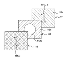
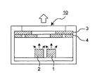
即ち、図31に示すように、表示装置10には、例えば赤色光を発する赤光源1と、例えば緑色光を発する緑光源2と、緑色光を遮光する赤色にてなる赤色フィルタ3と、赤色光を遮光する緑色にてなる緑色フィルタ4とが備わり、各光源1,2からの光が各フィルタ3、4を透過するように構成されている。又、赤色フィルタ3と緑色フィルタ4とは実際には合体され、一枚のフィルタとして形成されている。ここで、赤色フィルタ3には、図32の(ロ)に示すような、透明な又は開口にてなる円形意匠部分3aが形成され、それ以外の領域3bは赤色である。又、緑色フィルタ4には、図32の(ハ)に示すような赤色にてなるX形意匠部分4aが形成され、それ以外の領域4bは緑色である。上述のように、赤色フィルタ3と緑色フィルタ4とは一枚のフィルタであることから、図32の(イ)に示すように、円形意匠部分3aとX形意匠部分4aとは、同一箇所に位置する。   That is, as shown in FIG. 31, the display device 10 includes, for example, a red light source 1 that emits red light, a green light source 2 that emits green light, a red filter 3 that is red that blocks green light, and a red light. A green filter 4 made of green that blocks light is provided, and the light from each of the light sources 1 and 2 is transmitted through the filters 3 and 4. The red filter 3 and the green filter 4 are actually combined to form a single filter. Here, in the red filter 3, a circular design portion 3a that is transparent or has an opening as shown in FIG. 32B is formed, and the other region 3b is red. The green filter 4 is formed with an X-shaped design portion 4a in red as shown in FIG. 32C, and the other region 4b is green. As described above, since the red filter 3 and the green filter 4 are a single filter, as shown in FIG. 32A, the circular design portion 3a and the X-shaped design portion 4a are located at the same location. To position.

このように構成される従来の表示装置10は、以下のような表示動作を行う。即ち。赤光源1を点灯させたときには、赤色光は、赤色フィルタ3では、赤色領域3b、及び透明な又は開口にてなる円形意匠部分3aの両方を透過し、緑色フィルタ4では、緑色領域4bで遮光され赤色にてなるX形意匠部分4aを透過する。よって結果的に、赤光源1の点灯時には、X形意匠部分4aが赤色にて透過照明表示される。一方、緑光源2を点灯させたときには、緑色光は、赤色フィルタ3では、赤色領域3bで遮光され、透明な又は開口にてなる円形意匠部分3aを透過し、緑色フィルタ4では、緑色領域4bを透過し、赤色にてなるX形意匠部分4aで遮光される。よって結果的に、緑光源2の点灯時には、円形意匠部分3aが緑色にて透過照明表示される。
このように表示装置10では、光源1,2の点灯を切り替えることで、同一箇所に2つの意匠をそれぞれ独立して表示することができる。
The conventional display device 10 configured as described above performs the following display operation. That is. When the red light source 1 is turned on, the red light is transmitted through both the red region 3b and the transparent or open circular design portion 3a in the red filter 3, and is blocked by the green region 4b in the green filter 4. The red X-shaped design portion 4a is transmitted. Therefore, as a result, when the red light source 1 is turned on, the X-shaped design portion 4a is transmitted and displayed in red. On the other hand, when the green light source 2 is turned on, the green light is shielded by the red region 3b in the red filter 3 and is transmitted through the circular design portion 3a that is transparent or open, and the green region 4b in the green filter 4. Are shielded from light by the red X-shaped design portion 4a. Therefore, as a result, when the green light source 2 is turned on, the circular design portion 3a is transmitted and displayed in green.
As described above, in the display device 10, the two designs can be independently displayed at the same location by switching the lighting of the light sources 1 and 2.

実開昭61−171088号公報Japanese Utility Model Publication No. 61-171088

上述のように、従来の表示装置10では、赤光源1及び緑光源2のいずれかが点灯しているときには、円形意匠部分3a及びX形意匠部分4aをそれぞれ独立して表示することができる。しかしながら、赤光源1及び緑光源2の両方とも消灯しているときには、表示装置10の周りの外周光の作用により、円形意匠部分3a及びX形意匠部分4aの両方が図32の(イ)に示すように重なって見えてしまうという問題点がある。即ち、表示装置10は、例えば携帯電話等の操作部に用いることができるが、電池駆動されるモバイル機器等では、消費電力の低減が望まれている。よって、操作ボタン等の照明用光源は、必要時以外、消灯するのが一般的である。従って、モバイル機器等の操作部のように美観を重視する機器では、消灯時に不要な意匠パターンが見えることは大きな欠点となる。   As described above, in the conventional display device 10, when either the red light source 1 or the green light source 2 is lit, the circular design portion 3a and the X-shaped design portion 4a can be displayed independently. However, when both the red light source 1 and the green light source 2 are turned off, both the circular design portion 3a and the X-shaped design portion 4a are shown in FIG. As shown, there is a problem that they appear to overlap. In other words, the display device 10 can be used for an operation unit such as a mobile phone, but it is desired to reduce power consumption in a battery-driven mobile device or the like. Therefore, the illumination light source such as the operation button is generally turned off except when necessary. Therefore, in a device that places importance on aesthetics such as an operation unit such as a mobile device, it is a great disadvantage that an unnecessary design pattern can be seen when the light is turned off.

又、上述の問題点を解決するものとして、色フィルタ3,4の光透過側に、例えば黒色系のスモークフィルタをさらに設けた構成を開示する文献もある(例えば、日本国特許第3160166号)。しかしながら、上記スモークフィルタを設けることで、消灯時において複数の意匠パターンは見えにくくなるが、スモークフィルタは、全波長域の光を一様に遮光するものであることから、光源点灯時における意匠パターンの透過表示の輝度までも低下させてしまうという、新たな問題点を発生する。   Further, as a means for solving the above problems, there is a document disclosing a configuration in which, for example, a black smoke filter is further provided on the light transmitting side of the color filters 3 and 4 (for example, Japanese Patent No. 3160166). . However, the provision of the smoke filter makes it difficult to see a plurality of design patterns when the light is turned off, but the smoke filter uniformly blocks light in all wavelength ranges, so the design pattern when the light source is turned on. This causes a new problem that the brightness of the transmissive display is reduced.

本発明は、上述したような問題点を解決するためになされたもので、光源光が切り替えられることで、複数の意匠パターンをそれぞれ独立して透過照明表示し、かつ光源光の消灯時における美観をも損なわない表示フィルタ、及び該表示フィルタを有する表示モジュールを提供することを目的とする。   The present invention has been made to solve the above-described problems. By switching the light source light, a plurality of design patterns are individually transmitted and displayed, and the aesthetic appearance when the light source light is turned off is provided. Another object of the present invention is to provide a display filter that does not damage the display, and a display module having the display filter.

上記目的を達成するため、本発明は以下のように構成する。
即ち、本発明の第1態様における表示フィルタは、互いに重ね合わされる複数の意匠パターンフィルタと、
上記複数の意匠パターンフィルタを間に挟み光源とは反対側に位置する視認側に上記複数の意匠パターンフィルタと重ね合わされ配置される目隠しフィルタとを備え、
それぞれの上記意匠パターンフィルタは、特定波長域の光源光を透過する意匠パターンを有し上記意匠パターン外の素地部では上記特定波長域の光源光を吸収する吸収型のフィルタであり、互いに異なる意匠パターンを有し、かつそれぞれの上記特定波長域の光源光を吸収してそれぞれ異なる上記意匠パターンを表示し、
上記目隠しフィルタは、上記光源光が消灯状態で外周光により複数の上記意匠パターンが可視となるのを防止するフィルタであり、それぞれの上記意匠パターンを透過するそれぞれの上記特定波長域の光源光を透過し、かつそれぞれの上記特定波長域外の波長域の光を吸収する、
ことを特徴とする。
In order to achieve the above object, the present invention is configured as follows.
That is, the display filter in the first aspect of the present invention, a plurality of design pattern filters that are superposed on each other,
A blindfold filter that is arranged to overlap with the plurality of design pattern filters on the viewing side that is located on the opposite side of the light source with the plurality of design pattern filters interposed therebetween,
Each of the design pattern filters is an absorptive filter having a design pattern that transmits light source light in a specific wavelength region and absorbing the light source light in the specific wavelength region in the substrate portion outside the design pattern, and different designs Each having a pattern and displaying the design pattern different from each other by absorbing the light source light in the specific wavelength range,
The blindfold filter is a filter that prevents the plurality of design patterns from becoming visible due to ambient light when the light source light is turned off, and the light sources in the specific wavelength range that pass through the design patterns. Transmits light and absorbs light in a wavelength region outside the specific wavelength region.
It is characterized by that.

又、それぞれの上記意匠パターンフィルタ及び上記目隠しフィルタは、一枚のシート材として一体的に形成してもよい。この場合、一枚のシート材にインク印刷にて一体的に形成することもできる。   Each of the design pattern filter and the blindfold filter may be integrally formed as a single sheet material. In this case, it can be integrally formed on one sheet material by ink printing.

又、上記目隠しフィルタよりも上記視認側又は光源側に配置され、上記光源光が消灯状態であり上記外周光により可視となる表示意匠パターンを有する無彩色フィルタをさらに備えることもできる。   In addition, an achromatic filter having a display design pattern that is arranged on the viewing side or the light source side of the blindfold filter and that is visible when the light source light is off and the peripheral light is visible.

又、上記表示意匠パターンは、上記目隠しフィルタへのインク印刷により形成することができる。   The display design pattern can be formed by ink printing on the blindfold filter.

又、上記無彩色フィルタにおける上記表示意匠パターンは、透明又は半透明のシート材へインク印刷又は真空蒸着にて形成することができる。   The display design pattern in the achromatic filter can be formed on a transparent or translucent sheet material by ink printing or vacuum deposition.

又、上記無彩色フィルタにおける上記表示意匠パターンは、上記意匠パターンフィルタにおけるいずれかの意匠パターンと同一パターンであってもよい。   Further, the display design pattern in the achromatic color filter may be the same pattern as any design pattern in the design pattern filter.

又、それぞれの上記意匠パターンフィルタが吸収する上記光源光の上記特定波長域は、それぞれ独立しており重複しないようにしてもよいし、境界域で重複してもよい。   Further, the specific wavelength ranges of the light source light absorbed by the design pattern filters are independent and may not overlap with each other, or may overlap at a boundary region.

又、それぞれの上記意匠パターンフィルタに形成された各意匠パターンは、同一箇所に重複して配置することもできるし、重複せず、互いに独立した位置に配置することもできる。   In addition, each design pattern formed on each of the above-described design pattern filters can be arranged in duplicate at the same location, or can be arranged in an independent position without overlapping.

さらに本発明の第2態様における表示モジュールは、上記第1態様に記載するいずれかの表示フィルタと、
上記表示フィルタに含まれるそれぞれの意匠パターンフィルタが吸収する特定波長域の光源光を発する光源と、を備えたことを特徴とする。
Furthermore, the display module according to the second aspect of the present invention includes any one of the display filters described in the first aspect,
And a light source that emits light in a specific wavelength range that is absorbed by each of the design pattern filters included in the display filter.

上記第2態様において、上記光源は複数個設けられ、各光源は、それぞれの意匠パターンフィルタにおいて吸収されるそれぞれの特定波長域に対応した光源光をそれぞれ発し、
発光させる上記光源を切り替え、発光した光源からの光源光に対応する意匠パターンフィルタにおける意匠パターンを表示させる切替スイッチをさらに備えることもできる。
In the second aspect, a plurality of the light sources are provided, and each light source emits light source light corresponding to each specific wavelength region absorbed in each design pattern filter,
A changeover switch for switching the light source to emit light and displaying the design pattern in the design pattern filter corresponding to the light source light from the emitted light source can be further provided.

本発明の第1態様における表示フィルタによれば、複数の意匠パターンフィルタと、目隠しフィルタとが備わり、光源とは反対側の視認側に目隠しフィルタを配置し、目隠しフィルタは、それぞれの意匠パターンを透過するそれぞれの特定波長域の光源光を透過し、かつそれぞれの特定波長域外の波長域の光を吸収するように構成される。
よって、当該表示フィルタにおいて光源から光源光が照射されたときには、光源光が有する特定波長域を吸収する意匠パターンフィルタに描かれた意匠パターンを上記光源光が透過し目隠しフィルタに入射する。目隠しフィルタでは、上述のように、それぞれの上記意匠パターンを透過するそれぞれの特定波長域の光源光が透過することから、上記意匠パターンを透過した上記光源光は、目隠しフィルタを透過する。したがって、光源光が有する特定波長域を吸収する意匠パターンフィルタに描かれた意匠パターンを視認することができ、上記光源光を切り替えることで、複数の意匠パターンをそれぞれ独立して透過照明表示することができる。
According to the display filter in the first aspect of the present invention, a plurality of design pattern filters and a blindfold filter are provided, the blindfold filter is disposed on the viewing side opposite to the light source, and the blindfold filter The light source light of each specific wavelength range which permeate | transmits is transmitted, and it comprises so that the light of the wavelength range outside each specific wavelength range may be absorbed.
Therefore, when light source light is emitted from the light source in the display filter, the light source light passes through the design pattern drawn on the design pattern filter that absorbs the specific wavelength range of the light source light and enters the blind filter. In the blindfold filter, as described above, the light source light of each specific wavelength range that transmits each of the design patterns is transmitted. Therefore, the light source light that has transmitted the design pattern transmits the blindfold filter. Therefore, the design pattern drawn on the design pattern filter that absorbs the specific wavelength range of the light source light can be visually recognized, and a plurality of design patterns can be transmitted and displayed independently by switching the light source light. Can do.

一方、光源光が消灯されたときには、外周光が、目隠しフィルタに入射し、又、目隠しフィルタにて反射し、さらに、目隠しフィルタを透過した外周光は、それぞれの意匠パターンフィルタへ入射し、又、各意匠パターンフィルタで反射する。目隠しフィルタでは、上述のように、それぞれの上記意匠パターンを透過するそれぞれの特定波長域の光源光は透過され、かつそれぞれの特定波長域外の波長域の光は吸収される。よって、各意匠パターンフィルタで反射されて目隠しフィルタを透過した光は、各意匠パターンフィルタに対応したそれぞれの特定波長域を合成した波長域の光となる。よって、各意匠パターンフィルタの重なりによる色のバラツキを低減することができ、又、複数の意匠パターンフィルタに対して目隠しフィルタを加えることで、視認される色を黒色(無彩色)に近づけることができる。したがって、光源光が存在せず外周光のみが存在する場合に、各意匠パターンフィルタに形成されているそれぞれの意匠パターンを従来に比べて視認し難くすることができ、表示部分の美観の低下を防止することができる。   On the other hand, when the light source light is turned off, the ambient light is incident on the blindfold filter, reflected by the blindfold filter, and the ambient light transmitted through the blindfold filter is incident on each design pattern filter. Reflected by each design pattern filter. In the blindfold filter, as described above, the light source light in each specific wavelength range that passes through each of the design patterns is transmitted, and the light in the wavelength range outside the specific wavelength range is absorbed. Therefore, the light reflected by each design pattern filter and transmitted through the blindfold filter becomes light in a wavelength range obtained by synthesizing each specific wavelength range corresponding to each design pattern filter. Therefore, it is possible to reduce color variation due to the overlap of each design pattern filter, and by adding a blindfold filter to a plurality of design pattern filters, the visually recognized color can be brought close to black (achromatic color). it can. Therefore, when there is no light source light and only ambient light is present, it is possible to make each design pattern formed on each design pattern filter more difficult to see compared to the conventional case, and the appearance of the display portion is reduced. Can be prevented.

又、各意匠パターンフィルタ及び目隠しフィルタを一枚のシート材に形成することで、当該表示フィルタをよりコンパクトに形成可能となり、扱いやすくなる。   Further, by forming each design pattern filter and blindfold filter on a single sheet material, the display filter can be formed more compactly and is easy to handle.

さらに無彩色フィルタを備えることで、光源光が存在せず外周光のみが存在するときに、無彩色フィルタに備わる表示意匠パターンを表示させることができる。   Furthermore, by providing the achromatic color filter, it is possible to display the display design pattern provided in the achromatic color filter when the light source light does not exist and only the peripheral light exists.

又、無彩色フィルタを目隠しフィルタに印刷により形成することで、当該表示フィルタをよりコンパクトに形成可能となり、扱いやすくなる。一方、無彩色フィルタを透明又は半透明のシート材にて形成することで、無彩色フィルタの着脱が可能となる。又、無彩色フィルタに備わる表示意匠パターンを、いずれかの意匠パターンフィルタに備わる意匠パターンと同一とすることで、光源光が照射されたときには、表示意匠パターンは、上記光源光及び外周光の両方の作用によって、輝度をより向上させることができる。   In addition, by forming the achromatic color filter on the blind filter by printing, the display filter can be formed more compactly and easier to handle. On the other hand, the achromatic filter can be attached and detached by forming the achromatic filter with a transparent or translucent sheet material. Further, by making the display design pattern provided in the achromatic color filter the same as the design pattern provided in any of the design pattern filters, when the light source light is irradiated, the display design pattern is both the light source light and the peripheral light. The luminance can be further improved by the action of.

又、本発明の第2態様における表示モジュールによれば、上述した第1態様の表示フィルタを備えることから、複数の意匠パターンをそれぞれ独立して透過照明表示することができ、かつ光源光の消灯時においても美観の低下を防止することができる。   Further, according to the display module of the second aspect of the present invention, since the display filter of the first aspect described above is provided, a plurality of design patterns can be independently transmitted and displayed and the light source light can be turned off. Even at times, it is possible to prevent a decrease in aesthetics.

本発明の実施形態である表示フィルタ、及び該表示フィルタを備えた表示モジュールについて、図を参照しながら以下に説明する。尚、各図において、同一又は同様の構成部分については同じ符号を付している。又、各図において、点線によるハッチング及び網目模様は、断面を示すものではなく、以下に説明する各種の意匠パターンフィルタ、目隠しフィルタ、及び無彩色フィルタを表現するものである。一方、実線によるハッチングは、構造物の断面を示している。   A display filter according to an embodiment of the present invention and a display module including the display filter will be described below with reference to the drawings. In each figure, the same or similar components are denoted by the same reference numerals. Moreover, in each figure, the hatching and mesh pattern by a dotted line do not show a cross section, but represent various design pattern filters, blindfold filters, and achromatic filters described below. On the other hand, hatching with a solid line indicates a cross section of the structure.

第1実施形態;
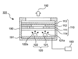
図1に示すように、本実施形態における表示モジュール101は、基本的構成部分として、表示フィルタ110と光源120とを備え、筐体190内に、回路基板191に実装された光源120に対向して表示フィルタ110を配置した構成を有する。さらに、光源120のオン、オフ、及び複数光源の切り替えを行う光源駆動回路部193を回路基板191に接続することができる。
このような構成により、表示モジュール101は、光源120から照射された光源光が表示フィルタ110を透過することで、表示フィルタ110に形成されている意匠パターンを視認側192にて視認させることができるとともに、光源120の消灯時において表示部の美観の低下を防止することができる。以下に、さらに詳しく説明する。
1st Embodiment;
As shown in FIG. 1, the display module 101 in this embodiment includes a display filter 110 and a light source 120 as basic components, and faces a light source 120 mounted on a circuit board 191 in a housing 190. The display filter 110 is arranged. Furthermore, a light source driving circuit unit 193 that turns on and off the light source 120 and switches a plurality of light sources can be connected to the circuit board 191.
With such a configuration, the display module 101 can make the design pattern formed on the display filter 110 visible on the viewing side 192 by allowing the light source light emitted from the light source 120 to pass through the display filter 110. In addition, it is possible to prevent a decrease in the appearance of the display unit when the light source 120 is turned off. This will be described in more detail below.

光源120は、複数色を発光可能な構造を有し、本実施形態では、青色の波長域の光を発する青色光源121と、赤色の波長域の光を発する赤色光源122とを備えている。このように光源120は、特定の波長域の光を発する必要があることから、例えばLED(発光ダイオード)、LD(レーザダイオード)、及びEL(エレクトロルミネッセンス)等を使用するのが好ましい。本実施形態では、青色光源121として、例えば465±20nmの特定波長域の光源光121aを発するLEDを使用し、赤色光源122として、例えば630±15nmの特定波長域の光源光122aを発するLEDを使用している。尚、赤色光源122の特定波長域として、605±15nmの光源光122aを使用することもできる。   The light source 120 has a structure capable of emitting a plurality of colors. In this embodiment, the light source 120 includes a blue light source 121 that emits light in a blue wavelength region and a red light source 122 that emits light in a red wavelength region. Thus, since the light source 120 needs to emit light in a specific wavelength range, it is preferable to use, for example, an LED (light emitting diode), an LD (laser diode), and an EL (electroluminescence). In the present embodiment, for example, an LED that emits light source light 121a in a specific wavelength range of 465 ± 20 nm is used as the blue light source 121, and an LED that emits light source light 122a in a specific wavelength range of 630 ± 15 nm is used as the red light source 122, for example. I use it. As a specific wavelength region of the red light source 122, a light source light 122a of 605 ± 15 nm can be used.

尚、本明細書において「特定波長域」とは、上述のように所定幅を有する波長帯を意味することは勿論のこと、該波長帯に含まれる一つの波長、例えば上記465nm等、のみをも指す場合も含む概念である。   In the present specification, the “specific wavelength range” means not only a wavelength band having a predetermined width as described above, but also only one wavelength included in the wavelength band, for example, the above-mentioned 465 nm. It is a concept that includes the case where

又、光源120は、上述の青色光源121及び赤色光源122に限定されるものではない。図11に示すように、既に存在し周知の緑色、黄緑色、黄色、オレンジ色等を発する各LED等を光源120として使用可能であり、さらに将来製造可能となるであろう発色光源をも使用可能である。
又、本実施形態では、光源120は、青色及び赤色の2色であるが、3色以上を発生させる構成とすることもできる。
The light source 120 is not limited to the blue light source 121 and the red light source 122 described above. As shown in FIG. 11, it is possible to use each already-existing and well-known LED emitting green, yellow-green, yellow, orange, or the like as the light source 120, and also use a color light source that may be manufactured in the future. Is possible.
In the present embodiment, the light source 120 has two colors of blue and red, but it may be configured to generate three or more colors.

又、本実施形態で使用する青色光源121及び赤色光源122では、互いの特定波長域が重なり合うことはないが、光源120から2つの特定波長域の光源光が発せられる場合に、2つの特定波長域の境界領域において重なり合うような2つの光源光を使用することもできる。さらに、3つ以上の特定波長域の光源光が発せられる場合、少なくとも2つの特定波長域の境界領域が重なり合うような光源光を使用することもできる。   In the blue light source 121 and the red light source 122 used in the present embodiment, the specific wavelength regions do not overlap each other, but when the light source light of two specific wavelength regions is emitted from the light source 120, the two specific wavelengths are emitted. It is also possible to use two light source lights that overlap in the boundary region. Furthermore, when the light source light of three or more specific wavelength ranges is emitted, the light source light in which the boundary regions of at least two specific wavelength ranges overlap can be used.

さらに又、構成が簡易なことから本実施形態では光源120として独立した2つの発色源を設けているが、光源120は、一つの光源と、複数の色フィルタとを有し、色フィルタの選択により発色を変更可能とした構造を採ることもできる。   In addition, since the configuration is simple, in the present embodiment, two independent color sources are provided as the light source 120. However, the light source 120 includes one light source and a plurality of color filters. Therefore, it is possible to adopt a structure in which the color development can be changed.

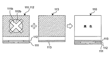
表示フィルタ110は、図1及び図2に示すように、青色の意匠パターンフィルタ111と、赤色の意匠パターンフィルタ112と、目隠しフィルタ113とを備え、本実施形態では拡散板114を付属している。これらのフィルタは、同一形状にてなり、かつ重なって配置され、光源120側から視認側192に向けて、拡散板114、青色の意匠パターンフィルタ111、赤色の意匠パターンフィルタ112、目隠しフィルタ113の順で、最も視認側192に目隠しフィルタ113が配置されている。又、このように構成される表示フィルタ110を保護するため、通常、目隠しフィルタ113よりも視認側192に透明なカバーが配置される。
尚、青色意匠パターンフィルタ111と、赤色意匠パターンフィルタ112とは、上述の順番に限らずに配置位置を交換してもよい。
As shown in FIGS. 1 and 2, the display filter 110 includes a blue design pattern filter 111, a red design pattern filter 112, and a blindfold filter 113, and a diffusion plate 114 is attached in the present embodiment. . These filters have the same shape and are arranged in an overlapping manner. From the light source 120 side to the viewing side 192, the diffusion plate 114, the blue design pattern filter 111, the red design pattern filter 112, and the blind filter 113 In order, the blindfold filter 113 is disposed on the most visible side 192. In order to protect the display filter 110 configured as described above, a transparent cover is usually disposed on the viewing side 192 relative to the blindfold filter 113.
The arrangement positions of the blue design pattern filter 111 and the red design pattern filter 112 may be exchanged without being limited to the order described above.

図示及び以下の説明では、図示及び理解を容易にするため、青色の意匠パターンフィルタ111、赤色の意匠パターンフィルタ112、及び目隠しフィルタ113は、それぞれ別個独立したシート材にて形成されるものとするが、当該第1実施形態及び後述する第2実施形態では、一枚のシート材にインク印刷処理にて、青色意匠パターンフィルタ111、赤色意匠パターンフィルタ112、及び目隠しフィルタ113が一体的に形成されている。勿論、以下の説明のように、それぞれ別個独立したシート材にて形成した、青色意匠パターンフィルタ111、赤色意匠パターンフィルタ112、及び目隠しフィルタ113を重ね合わせて、例えば貼り合わせることで一体的に表示フィルタ110を形成してもよい。
又、一枚のシート材への蒸着処理により、青色意匠パターンフィルタ111、赤色意匠パターンフィルタ112、及び目隠しフィルタ113を一体的に形成することもできる。
In the drawings and the following description, for ease of illustration and understanding, the blue design pattern filter 111, the red design pattern filter 112, and the blindfold filter 113 are each formed of a separate and independent sheet material. However, in the first embodiment and the second embodiment to be described later, the blue design pattern filter 111, the red design pattern filter 112, and the blindfold filter 113 are integrally formed on one sheet material by ink printing processing. ing. Of course, as described below, the blue design pattern filter 111, the red design pattern filter 112, and the blindfold filter 113, which are formed of separate and independent sheet materials, are overlapped and displayed, for example, by bonding them together. The filter 110 may be formed.
Further, the blue design pattern filter 111, the red design pattern filter 112, and the blindfold filter 113 can be integrally formed by vapor deposition on one sheet material.

表示フィルタ110を構成する各意匠パターンフィルタ111,112は、光源120が発する上記特定波長域の光源光を吸収する吸収型のフィルタである。即ち、本実施形態では、光源120として、上述の特定波長域の光源光121aを発する青色光源121と、上述の特定波長域の光源光122aを発する赤色光源122とを有することから、図12及び図14に示すような、赤色の光源光122aにおける特定波長域の光を吸収する青色の意匠パターンフィルタ111と、図13及び図15に示すような、青色の光源光121aにおける特定波長域の光を吸収する赤色の意匠パターンフィルタ112とが設けられる。このように、意匠パターンフィルタは、設置した光源120が発する複数色の光源光、つまり複数の特定波長域に対応して、複数、設けられる。   The design pattern filters 111 and 112 constituting the display filter 110 are absorption type filters that absorb the light source light in the specific wavelength range emitted from the light source 120. That is, in this embodiment, the light source 120 includes the blue light source 121 that emits the light source light 121a in the specific wavelength range described above and the red light source 122 that emits the light source light 122a in the specific wavelength range described above. The blue design pattern filter 111 that absorbs light in a specific wavelength range in the red light source light 122a as shown in FIG. 14 and the light in the specific wavelength range in the blue light source light 121a as shown in FIGS. And a red design pattern filter 112 that absorbs light. As described above, a plurality of design pattern filters are provided corresponding to a plurality of colors of light source light emitted from the installed light source 120, that is, a plurality of specific wavelength regions.

尚、図12には、赤色光源122の発光特性、換言すると特定波長域122b(実線)に対する青色意匠パターンフィルタ111における光波長の透過特性111c(点線)を図示し、図13には、青色光源121の発光特性、換言すると特定波長域121b(点線)に対する赤色意匠パターンフィルタ112における光波長の透過特性112c(実線)を図示している。
ここで、図12に示す青色意匠パターンフィルタ111における光波長の透過特性111c、及び図13に示す赤色意匠パターンフィルタ112における光波長の透過特性112cは、意匠パターンフィルタ111,112におけるそれぞれ理想的な透過特性を示している。意匠パターンフィルタ111,112の素地部111a,112aを蒸着処理にて形成した場合には、比較的、上記理想的な透過特性に近い特性を得ることができる。
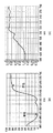
FIG. 12 shows the light emission characteristics of the red light source 122, in other words, the transmission characteristics 111c (dotted line) of the light wavelength in the blue design pattern filter 111 with respect to the specific wavelength range 122b (solid line), and FIG. The light emission characteristic 121, in other words, the light wavelength transmission characteristic 112c (solid line) in the red design pattern filter 112 for the specific wavelength region 121b (dotted line) is illustrated.
Here, the transmission characteristic 111c of the light wavelength in the blue design pattern filter 111 shown in FIG. 12 and the transmission characteristic 112c of the light wavelength in the red design pattern filter 112 shown in FIG. 13 are ideal for the design pattern filters 111 and 112, respectively. The transmission characteristics are shown. When the substrate portions 111a and 112a of the design pattern filters 111 and 112 are formed by vapor deposition, characteristics that are relatively close to the ideal transmission characteristics can be obtained.

又、図14の(a)、(b)には、青色意匠パターンフィルタ111の素地部111aをインク印刷にて形成した場合の青色意匠パターンフィルタ111における、光波長に対する透過率及び反射率をそれぞれ図示し、図15の(a)、(b)には、赤色意匠パターンフィルタ112の素地部112aをインク印刷にて形成した場合の赤色意匠パターンフィルタ112における、光波長に対する透過率、及び反射率をそれぞれ図示している。   14A and 14B show the transmittance and reflectance with respect to the light wavelength in the blue design pattern filter 111 when the base portion 111a of the blue design pattern filter 111 is formed by ink printing, respectively. FIGS. 15A and 15B show the transmittance and the reflectance with respect to the light wavelength in the red design pattern filter 112 when the base portion 112a of the red design pattern filter 112 is formed by ink printing. Respectively.

又、それぞれの意匠パターンフィルタ111、112には、青色光源121及び赤色光源122のいずれかが点灯したときに視認させる意匠パターンがそれぞれ形成されている。即ち、本実施形態では図2に示すように、青色の意匠パターンフィルタ111には、青色の素地部111aに対して、例えばバツ印にてなる意匠パターン111bが透明に又は開口にて形成され、赤色の意匠パターンフィルタ112には、赤色の素地部112aに対して、例えば丸印にてなる意匠パターン112bが透明に又は開口にて形成されている。これらの各意匠パターン111b、112bは、本実施形態では、図3に示すように、互いに重なって配置される。尚、図10に示すように、各意匠パターン111b、112bを重ならせずに、互いに独立した位置、例えば隣接位置に配置することもできる。この場合、各意匠パターンを同一とし、例えばその向きを「―」、「|」のように変更することもできる。   The design pattern filters 111 and 112 are respectively formed with design patterns that are visually recognized when one of the blue light source 121 and the red light source 122 is turned on. That is, in the present embodiment, as shown in FIG. 2, the blue design pattern filter 111 is formed with a design pattern 111b made of, for example, a cross mark transparently or in an opening with respect to the blue base portion 111a. In the red design pattern filter 112, a design pattern 112b made of, for example, a circle is formed transparently or in an opening with respect to the red base portion 112a. In the present embodiment, these design patterns 111b and 112b are arranged so as to overlap each other as shown in FIG. As shown in FIG. 10, the design patterns 111b and 112b can be arranged at positions independent from each other, for example, adjacent positions without overlapping each other. In this case, each design pattern can be made the same, and the direction thereof can be changed to “-”, “|”, for example.

したがって、意匠パターンフィルタ111、112は、図12〜図15に示す特性から明らかなように、以下のように作用する。
即ち、赤色光源122が点灯したときには、赤色光源光122aは、青色の意匠パターンフィルタ111の素地部111aでは吸収され、一方、透明又は開口にてなるバツ印にてなる意匠パターン111bを透過して、赤色の意匠パターンフィルタ112へ入射する。赤色の意匠パターンフィルタ112では、赤色光源光122aは、素地部112a、さらに透明又は開口にてなる円形の意匠パターン112b部分を透過する。よって、赤色光源122が点灯したときには、青色の意匠パターンフィルタ111におけるバツ印の意匠パターン111bが赤色にて表示される。
又、青色光源121が点灯したときには、青色光源光121aは、青色の意匠パターンフィルタ111の素地部111a、及び透明又は開口にてなる意匠パターン111bを透過して、つまりバツ印の意匠パターン111bを表示することなく赤色の意匠パターンフィルタ112へ入射する。赤色の意匠パターンフィルタ112では、青色光源光121aは、素地部112aでは吸収され、透明又は開口にてなる円形の意匠パターン112b部分を透過する。よって、青色光源121が点灯したときには、赤色の意匠パターンフィルタ112における丸印の意匠パターン112bが青色にて表示される。
Therefore, the design pattern filters 111 and 112 operate as follows, as is apparent from the characteristics shown in FIGS.
That is, when the red light source 122 is turned on, the red light source light 122a is absorbed by the base portion 111a of the blue design pattern filter 111, while being transmitted through the design pattern 111b that is a transparent or open cross mark. , And enters the red design pattern filter 112. In the red design pattern filter 112, the red light source light 122a is transmitted through the base portion 112a and the circular design pattern 112b portion that is transparent or has an opening. Therefore, when the red light source 122 is turned on, the cross-shaped design pattern 111b in the blue design pattern filter 111 is displayed in red.
When the blue light source 121 is turned on, the blue light source light 121a passes through the base portion 111a of the blue design pattern filter 111 and the design pattern 111b made of transparent or opening, that is, passes through the cross-shaped design pattern 111b. The light enters the red design pattern filter 112 without displaying. In the red design pattern filter 112, the blue light source light 121 a is absorbed by the base portion 112 a and passes through a transparent design or circular design pattern 112 b portion. Therefore, when the blue light source 121 is turned on, the circular design pattern 112b in the red design pattern filter 112 is displayed in blue.

次に、本実施形態において特徴的構成部分の一つである目隠しフィルタ113について説明する。
目隠しフィルタ113は、光源120からの光源光121a、122aが消灯状態のときに外周光のみによって複数の意匠パターン111b、112bが可視となるのを防止するフィルタであって、図1に示すように、意匠パターンフィルタ111,112を間に挟み光源120とは反対側に位置する視認側192に、意匠パターンフィルタ111,112と重ね合わされて配置される。このような目隠しフィルタ113は、それぞれの意匠パターン111b、112bを透過するそれぞれの上記特定波長域の光源光122a,121aを透過し、かつそれぞれの上記特定波長域外の波長域の光を吸収し、反射光成分を減らす。
Next, the blindfold filter 113 that is one of characteristic components in the present embodiment will be described.
The blindfold filter 113 is a filter that prevents the plurality of design patterns 111b and 112b from being visible only by the peripheral light when the light source lights 121a and 122a from the light source 120 are turned off, as shown in FIG. The design pattern filters 111 and 112 are sandwiched between the design pattern filters 111 and 112 on the viewing side 192 located on the opposite side of the light source 120. Such a blind filter 113 transmits the light source lights 122a and 121a in the specific wavelength range that pass through the design patterns 111b and 112b, and absorbs light in the wavelength range outside the specific wavelength range, Reduce reflected light components.

図16及び図17を参照して具体的に説明する。図16には、上述した、図12に示す、赤色光源122の発光特性122bに対する青色意匠パターンフィルタ111の光波長透過特性111c、及び、図13に示す、青色光源121の発光特性121bに対する赤色意匠パターンフィルタ112の光波長透過特性112cに加えて、目隠しフィルタ113の光波長透過特性113cを図示している。尚、光波長透過特性113cは、理想的な透過特性を示しており、目隠しフィルタ113を蒸着処理にて形成した場合には、比較的、上記理想的な透過特性に近い特性を得ることができる。又、図17の(a)、(b)には、目隠しフィルタ113をインク印刷にて形成した場合の光波長に対する透過率及び反射率をそれぞれ図示している。   This will be specifically described with reference to FIGS. 16 and 17. 16 shows the light wavelength transmission characteristic 111c of the blue design pattern filter 111 with respect to the emission characteristic 122b of the red light source 122 shown in FIG. 12 and the red design with respect to the emission characteristic 121b of the blue light source 121 shown in FIG. In addition to the light wavelength transmission characteristic 112c of the pattern filter 112, the light wavelength transmission characteristic 113c of the blind filter 113 is illustrated. The light wavelength transmission characteristic 113c shows an ideal transmission characteristic. When the blindfold filter 113 is formed by vapor deposition, a characteristic that is relatively close to the ideal transmission characteristic can be obtained. . FIGS. 17A and 17B show the transmittance and reflectance with respect to the light wavelength when the blindfold filter 113 is formed by ink printing.

図16及び図17から明らかなように、目隠しフィルタ113は、青色光源121が発する例えば465±20nmの特定波長域121bの光源光121a、及び、赤色光源122が発する例えば630±15nmの特定波長域122bの光源光122aをほぼ100%透過するが、一方、これらの特定波長域以外の波長域、つまり約560nm付近を中心とした波長域の光をほぼ100%吸収する。尚、目隠しフィルタ113、並びに青色の意匠パターンフィルタ111及び赤色の意匠パターンフィルタ112をインク印刷にて形成した場合、これらのフィルタの透過率、反射率及び吸収率について、理論的には、透過率+反射率+吸収率=1の関係があり、さらに、インク印刷で使用される顔料では、透過率と反射率との間には相関関係がある。つまり、例えば透過率が上がれば反射率も上がる。このような光波長の吸収、透過特性を有することから、目隠しフィルタ113を色で表現すると、各光源光121a,122aの青色と赤色とを合成した合成色、つまり紫色(マゼンタ)である。   As apparent from FIGS. 16 and 17, the blindfold filter 113 includes the light source light 121 a in the specific wavelength range 121 b of 465 ± 20 nm emitted from the blue light source 121 and the specific wavelength range of 630 ± 15 nm emitted from the red light source 122. Although the light source light 122a of 122b is transmitted almost 100%, it absorbs almost 100% of light in a wavelength region other than these specific wavelength regions, that is, a wavelength region centered around about 560 nm. When the blindfold filter 113, the blue design pattern filter 111, and the red design pattern filter 112 are formed by ink printing, the transmittance, the reflectance, and the absorptance of these filters are theoretically the transmittance. There is a relationship of + reflectance + absorption rate = 1, and furthermore, in the pigment used in ink printing, there is a correlation between transmittance and reflectance. That is, for example, if the transmittance increases, the reflectance also increases. Because of having such light wavelength absorption and transmission characteristics, when the blind filter 113 is expressed in color, it is a composite color obtained by combining the blue and red light of each of the light source lights 121a and 122a, that is, purple (magenta).

本実施形態の目隠しフィルタ113では、上述のように特定波長域の光源光の透過率はほぼ100%、特定波長域外の光源光の吸収率はほぼ0%である光波長の吸収、透過特性を有する。又、本実施形態のように特定波長域121bの青色の光源光121a及び特定波長域122bの赤色の光源光122aに対して、目隠しフィルタ113としての以下に説明するような機能を果たすためには、目隠しフィルタ113は、目隠しフィルタ113の理想に近い透過特性の一例を示す図18に示すような矩形の透過特性を有するのが好ましい。一方、光源120からの光源光121a、122aが消灯状態のときに外周光のみによって複数の意匠パターン111b、112bを視認できなくする観点からすれば、目隠しフィルタ113の透過率は、低い程よく例えば10%以下であってもよい。しかしながらこのような低い透過率では、光源120の点灯時に光源光121a、122aが目隠しフィルタ113を透過できず、意匠パターン111b、112bの視認ができなくなってしまう。又、現状では実際のところ図17の(a)に示すように、インク印刷にて目隠しフィルタ113を形成した場合における青色及び赤色の特定波長域における透過率は、40%前後であり、この程度の透過率で十分に目隠しフィルタ113の機能を果たすことが可能である。したがって、目隠しフィルタ113としての以下に説明するような機能を果たすためには、約40%前後から、好ましくは70%以上、より好ましくは80%以上の特定波長域の光源光の透過率、及び95%以上の上記特定波長域外の波長域の光の吸収率が備わっていれば良いことが確認されている。   In the blindfold filter 113 of the present embodiment, as described above, the light wavelength absorption and transmission characteristics are approximately 100% for the light source light in the specific wavelength range and about 0% for the light source light outside the specific wavelength range. Have. In order to fulfill the functions described below as the blindfold filter 113 for the blue light source light 121a in the specific wavelength range 121b and the red light source light 122a in the specific wavelength range 122b as in the present embodiment. The blindfold filter 113 preferably has a rectangular transmission characteristic as shown in FIG. 18 showing an example of a transmission characteristic close to the ideal of the blindfold filter 113. On the other hand, from the viewpoint of making the plurality of design patterns 111b and 112b invisible only by the peripheral light when the light source lights 121a and 122a from the light source 120 are turned off, the transmittance of the blindfold filter 113 is preferably as low as 10 for example. % Or less. However, with such a low transmittance, the light source lights 121a and 122a cannot pass through the blindfold filter 113 when the light source 120 is turned on, and the design patterns 111b and 112b cannot be visually recognized. Further, as shown in FIG. 17A, the transmittance in the specific wavelength range of blue and red is about 40% when the blind filter 113 is formed by ink printing. It is possible to fulfill the function of the blindfold filter 113 with a sufficient transmittance. Therefore, in order to perform the function as described below as the blindfold filter 113, the transmittance of the light source light in a specific wavelength region of about 40%, preferably 70% or more, more preferably 80% or more, and It has been confirmed that a light absorptance of a wavelength region outside the specific wavelength region of 95% or more should be provided.

又、青色の光源光121a、及び赤色の光源光122a以外の2又は3以上の波長域の光源光が用いられる場合であっても、目隠しフィルタ113が上述の光源光の透過率及び吸収率を備えることで、複数の光源120からの各特定波長域にかかわらず、目隠しフィルタ113としての以下に説明するような機能を果たすことができる。   Further, even when the light source light having two or more wavelength ranges other than the blue light source light 121a and the red light source light 122a is used, the blindfold filter 113 has the above-described transmittance and absorption rate of the light source light. By providing, regardless of each specific wavelength range from the plurality of light sources 120, the function as described below as the blind filter 113 can be achieved.

又、上述したように、目隠しフィルタ113は、意匠パターンフィルタ111、112に対して最も視認側192に配置されることから、意匠パターンフィルタ112を出射した光は、目隠しフィルタ113に入射する。これに対し目隠しフィルタ113は、上述の光波長透過、吸収特性を有することから、青色光源121が点灯したときに赤色の意匠パターンフィルタ112にて表現される青色の円形の意匠パターン112b、及び、赤色光源122が点灯したときに青色の意匠パターンフィルタ111にて表現される赤色のバツ印の意匠パターン111bは、それぞれ透過率が低下することなく、そのまま視認可能である。この点で、目隠しフィルタ113は、従来用いられている、いわゆるスモークフィルタと大きく特性を異にする。   Further, as described above, the blindfold filter 113 is disposed on the most visible side 192 with respect to the design pattern filters 111 and 112, so that the light emitted from the design pattern filter 112 enters the blindfold filter 113. On the other hand, the blindfold filter 113 has the light wavelength transmission and absorption characteristics described above, and therefore, a blue circular design pattern 112b expressed by the red design pattern filter 112 when the blue light source 121 is turned on, and When the red light source 122 is turned on, the red cross-shaped design pattern 111b expressed by the blue design pattern filter 111 is visible as it is without any decrease in transmittance. In this respect, the blindfold filter 113 is greatly different in characteristics from a so-called smoke filter conventionally used.

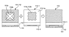
上述の目隠しフィルタ113は、図3に示すように、その全面に対して、上述の光波長の吸収、透過特性を有するように構成してもよいし、あるいは図4に示す目隠しフィルタ113−1のように、各意匠パターン111b、112bに対応する部分に対して上述の光波長の吸収、透過特性を有し、各意匠パターン111b、112b以外の領域113−1aについては透明に構成してもよい。   As shown in FIG. 3, the above-described blindfold filter 113 may be configured to have the above-described light wavelength absorption and transmission characteristics over the entire surface, or the blindfold filter 113-1 shown in FIG. 4. As described above, the portions corresponding to the design patterns 111b and 112b have the above-described absorption and transmission characteristics of the light wavelength, and the region 113-1a other than the design patterns 111b and 112b may be configured to be transparent. Good.

上述のように最も視認側192に目隠しフィルタ113を配置することで、目隠しフィルタ113は、さらに以下の作用を行う。
青色光源121及び赤色光源122が消灯し光源光が存在しないときには、全波長を含む外周光が、目隠しフィルタ113に入射し、あるいは目隠しフィルタ113の表面にて反射し、さらに、目隠しフィルタ113を透過した外周光は、それぞれの意匠パターンフィルタ111,112へ入射し、又、各意匠パターンフィルタ111,112の表面で反射する。目隠しフィルタ113では、上述のように、それぞれの意匠パターン111b、112bを透過するそれぞれの特定波長域の光源光122a、121aは透過され、かつそれぞれの特定波長域外の波長域の光は吸収される。よって、各意匠パターンフィルタ111,112で反射され目隠しフィルタ113を透過した光は、各意匠パターンフィルタ111,112に対応したそれぞれの特定波長域を合成した波長域の光となる。よって、各意匠パターンフィルタ111,112の重なりによる色のバラツキを低減させることができ、又、各意匠パターンフィルタ111,112に目隠しフィルタ113を加えることで、視認される色を黒色(無彩色)に近づけることができる。したがって、青色光源121及び赤色光源122が消灯した状態で外周光のみが存在するときに、各意匠パターンフィルタ111,112に形成されているそれぞれの意匠パターン111b、112bを従来に比べて視認し難くすることができ、表示部分の美観の低下を防止することができる。
By arranging the blindfold filter 113 on the most visible side 192 as described above, the blindfold filter 113 further performs the following actions.
When the blue light source 121 and the red light source 122 are turned off and there is no light source light, the peripheral light including all wavelengths is incident on the blindfold filter 113 or is reflected by the surface of the blindfold filter 113 and further passes through the blindfold filter 113. The outer peripheral light that has entered the design pattern filters 111 and 112 is reflected by the surfaces of the design pattern filters 111 and 112. In the blindfold filter 113, as described above, the light source lights 122a and 121a in the specific wavelength ranges that pass through the design patterns 111b and 112b are transmitted, and light in the wavelength ranges outside the specific wavelength ranges is absorbed. . Therefore, the light reflected by the design pattern filters 111 and 112 and transmitted through the blind filter 113 becomes light in a wavelength range obtained by synthesizing the specific wavelength ranges corresponding to the design pattern filters 111 and 112. Therefore, the variation in color due to the overlap of the design pattern filters 111 and 112 can be reduced, and the blinded filter 113 is added to the design pattern filters 111 and 112 so that the visible color is black (achromatic color). Can be approached. Therefore, when only the peripheral light is present with the blue light source 121 and the red light source 122 turned off, it is difficult to visually recognize the design patterns 111b and 112b formed on the design pattern filters 111 and 112 as compared with the related art. It is possible to prevent a decrease in the aesthetic appearance of the display portion.

上記消灯状態にて、各意匠パターン111b、112bを従来に比べて見えにくくすることができることについて、図5〜図9を参照してさらに詳しく説明する。
まず、上記消灯状態で外周光のみが存在する場合で、目隠しフィルタ113を設けないときには、各意匠パターンフィルタ111,112に形成されているそれぞれの意匠パターン111b、112bがうっすらと見えてしまう原理を説明する。
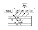
上記消灯状態で外周光のみが存在する場合において、積層された複数層によって視認される表示つまり反射光は、図5に示すように、各層で透過反射したものが合成されて見える。これは、視覚の特性より、赤(R)、青(B)、緑(G)成分の合成で考えることができ、上記合成されて見える反射光(Ref)は、各層で透過反射したもの(ref1〜refn)を加算して求まり、下記の式にて表すことができる。
The fact that each of the design patterns 111b and 112b can be made harder to see in the light-off state than in the prior art will be described in more detail with reference to FIGS.
First, the principle that the design patterns 111b and 112b formed on the design pattern filters 111 and 112 are slightly visible when only the peripheral light is present in the light-off state and the blindfold filter 113 is not provided. explain.
When only the peripheral light is present in the light-off state, the display, that is, the reflected light that is visually recognized by the stacked layers, that is, the reflected light, appears to be synthesized by the transmission and reflection of the respective layers as shown in FIG. This can be considered by the composition of red (R), blue (B), and green (G) components from the viewpoint of visual characteristics, and the reflected light (Ref) that appears to be synthesized is transmitted and reflected by each layer ( ref1 to refn) are added and can be expressed by the following formula.

Ref=ref1 + ref2 + ref3 +・・・+ refn
=(r1)+(T1*T1*r2)+(T1*T2*T1*T2*r3) +・・・+(T1*T1*T2*T2*…Tn-1*Tn-1*rn)
ここで、r: 反射率(rn:n層目の反射率)、T:透過率(Tn:n層目の透過率)。
Ref = ref1 + ref2 + ref3 + ... + refn
= (R1) + (T1 * T1 * r2) + (T1 * T2 * T1 * T2 * r3) + ... + (T1 * T1 * T2 * T2 * ... Tn-1 * Tn-1 * rn)
Here, r: reflectance (rn: reflectance of the nth layer), T: transmittance (Tn: transmittance of the nth layer).

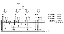
上述の原理に基づいて、図6では、目隠しフィルタ113が存在しない場合に外周光194が青色意匠パターンフィルタ111及び赤色意匠パターンフィルタ112に作用する状態を図示し、図7では、目隠しフィルタ113を設けた場合に外周光194が青色意匠パターンフィルタ111及び赤色意匠パターンフィルタ112に作用する状態を図示している。   Based on the above principle, FIG. 6 illustrates a state in which the ambient light 194 acts on the blue design pattern filter 111 and the red design pattern filter 112 when the blindfold filter 113 is not present, and FIG. The state in which the peripheral light 194 acts on the blue design pattern filter 111 and the red design pattern filter 112 when provided is illustrated.

即ち、図6に示すように、RGB成分を有する外周光194が赤色意匠パターンフィルタ112、青色意匠パターンフィルタ111、赤色意匠パターンフィルタ112と青色意匠パターンフィルタ111とが重なっているマゼンタ部分、及び無色透明部分に作用することで、赤色意匠パターンフィルタ112部分及び上記マゼンタ部分からは主に赤色波長域の光が視認側192へ出射され、青色意匠パターンフィルタ111からは主に青色波長域の光が視認側192へ出射され、上記無色透明部分からは赤色、緑色、及び青色波長域の光が視認側192へ出射される。   That is, as shown in FIG. 6, the ambient light 194 having RGB components is a red design pattern filter 112, a blue design pattern filter 111, a magenta portion where the red design pattern filter 112 and the blue design pattern filter 111 are superposed, and colorless. By acting on the transparent portion, light in the red wavelength region is mainly emitted from the red design pattern filter 112 portion and the magenta portion to the viewing side 192, and light in the blue wavelength region is mainly emitted from the blue design pattern filter 111. Light is emitted to the viewing side 192, and light in the red, green, and blue wavelength regions is emitted from the colorless and transparent portion to the viewing side 192.

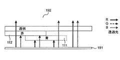
一方、図7に示すように、視認側192に目隠しフィルタ113を配置した本実施形態の表示フィルタ110の構成では、RGB成分を有する外周光194が表示フィルタ110に入射することで、以下のような作用が生じる。即ち、目隠しフィルタ113では上述のように緑色波長域の光を吸収することから、目隠しフィルタ113からは青色波長域の光、及び赤色波長域の光が視認側192へ出射される。又、赤色意匠パターンフィルタ112部分では、緑色波長域の光は目隠しフィルタ113にてほぼ吸収され赤色意匠パターンフィルタ112まで到達せず、青色波長域の光は目隠しフィルタ113を透過するが当該赤色意匠パターンフィルタ112にて吸収される。よって、赤色意匠パターンフィルタ112部分からは、赤色波長域の光が目隠しフィルタ113を透過して出射されるとともに、目隠しフィルタ113の表面にて反射した青色及び赤色の波長域の光が視認側192へ出射される。又、上記マゼンタ部分では、赤色意匠パターンフィルタ112の表面で反射し目隠しフィルタ113を透過した赤色波長域の光、及び目隠しフィルタ113の表面にて反射した青色及び赤色の波長域の光が視認側192へ出射される。又、青色意匠パターンフィルタ111部分では、青色意匠パターンフィルタ111の表面で反射し目隠しフィルタ113を透過した青色波長域の光、及び目隠しフィルタ113の表面にて反射した青色及び赤色の波長域の光が視認側192へ出射される。   On the other hand, as shown in FIG. 7, in the configuration of the display filter 110 of the present embodiment in which the blindfold filter 113 is arranged on the viewing side 192, the peripheral light 194 having RGB components is incident on the display filter 110 as follows. The effect occurs. In other words, since the blindfold filter 113 absorbs light in the green wavelength range as described above, light in the blue wavelength range and light in the red wavelength range are emitted from the blindfold filter 113 to the viewing side 192. Further, in the red design pattern filter 112 portion, the light in the green wavelength range is almost absorbed by the blindfold filter 113 and does not reach the red design pattern filter 112, and the light in the blue wavelength range passes through the blindfold filter 113, but the red design pattern Absorbed by the pattern filter 112. Therefore, from the red design pattern filter 112 portion, light in the red wavelength range is transmitted through the blindfold filter 113 and emitted in the blue and red wavelength ranges reflected on the surface of the blindfold filter 113. Is emitted. In the magenta portion, the red wavelength band light reflected on the surface of the red design pattern filter 112 and transmitted through the blindfold filter 113, and the blue and red wavelength band lights reflected on the surface of the blindfold filter 113 are visible. The light is emitted to 192. Further, in the blue design pattern filter 111 portion, light in the blue wavelength range reflected on the surface of the blue design pattern filter 111 and transmitted through the blindfold filter 113, and light in the blue and red wavelength ranges reflected on the surface of the blindfold filter 113. Is emitted to the viewing side 192.

このように目隠しフィルタ113を配置した本実施形態の表示フィルタ110の構成では、外周光194によって視認側192へ出射される光の波長域は、赤色意匠パターンフィルタ112部分、マゼンタ部分、青色意匠パターンフィルタ111部分、及び透明部分のいずれにおいても、青色及び赤色の波長域となる。したがって、視認側192では、色むらが認識され難い。即ち、光源120が消灯状態において、各意匠パターン111b、112bを従来に比べて見えにくくすることができる。   In the configuration of the display filter 110 of the present embodiment in which the blindfold filter 113 is arranged in this way, the wavelength range of the light emitted to the viewing side 192 by the peripheral light 194 is the red design pattern filter 112 portion, the magenta portion, and the blue design pattern. Both the filter 111 portion and the transparent portion have blue and red wavelength ranges. Therefore, the color unevenness is hardly recognized on the viewing side 192. That is, when the light source 120 is turned off, the design patterns 111b and 112b can be made harder to see than in the past.

さらに又、色フィルタの素材が光の吸収特性を有する場合、減色法の理論よりマゼンタ+青+赤でより黒に近づく。よって、本実施形態におけるマゼンタ色の目隠しフィルタ113と、青色の意匠パターンフィルタ111、及び赤色の意匠パターンフィルタ112とが混色されることで黒色(無彩色)に近づけることができる。この点からも、目隠しフィルタ113を設けることで、特に本実施形態の構成では、光源120の消灯状態において各意匠パターン111b、112bを従来に比べて見えにくくすることができる。
尚、理想の黒色とするには、Y(イエロー)+C(シアン)+M(マゼンタ)が望ましい。よって、このような組み合わせとなる光の波長域を有するように、光源120、意匠パターンフィルタ、及び目隠しフィルタを構成することで、光源120の消灯状態において各意匠パターン111b、112bをほぼ視認不可とすることができる。
Furthermore, when the material of the color filter has a light absorption characteristic, magenta + blue + red is closer to black than the theory of the subtractive color method. Therefore, the magenta blindfold filter 113, the blue design pattern filter 111, and the red design pattern filter 112 according to the present embodiment can be mixed to be close to black (achromatic color). Also from this point, by providing the blindfold filter 113, it is possible to make the design patterns 111b and 112b less visible in the configuration of the present embodiment when the light source 120 is turned off compared to the conventional case.
In order to obtain an ideal black color, Y (yellow) + C (cyan) + M (magenta) is desirable. Therefore, by configuring the light source 120, the design pattern filter, and the blindfold filter so as to have the wavelength range of light in such a combination, the design patterns 111b and 112b are almost invisible in the light-off state of the light source 120. can do.

尚、目隠しフィルタ113を設けた構成にあっても、青色光源121及び赤色光源122が点灯状態であるときには、上述したように、及び図9に示すように、青色の光源光121a及び赤色の光源光122aが目隠しフィルタ113を透過して視認側192に到達可能である。図8では、目隠しフィルタ113を設けていない場合を示し、青色の光源光121a及び赤色の光源光122aは、視認側192に到達している。   Even when the blind filter 113 is provided, when the blue light source 121 and the red light source 122 are in the lighting state, as described above and as shown in FIG. 9, the blue light source light 121a and the red light source are provided. The light 122 a can pass through the blindfold filter 113 and reach the viewing side 192. FIG. 8 shows a case where the blindfold filter 113 is not provided, and the blue light source light 121 a and the red light source light 122 a reach the viewing side 192.

以上説明したように本実施形態の表示フィルタ110によれば、光源120が点灯状態であるときには、光源光が有する特定波長域を吸収する意匠パターンフィルタに描かれた意匠パターンを透過照明表示することができる。一方、光源120が消灯状態であり外周光194のみが目隠しフィルタ113及び複数の意匠パターンフィルタ111,112に入射するときには、目隠しフィルタ113により、各意匠パターンフィルタ111,112に形成されているそれぞれの意匠パターン111b、112bを従来に比べて見えにくくすることができ、表示部分の美観の低下を防止することができる。   As described above, according to the display filter 110 of the present embodiment, when the light source 120 is in the lighting state, the design pattern drawn on the design pattern filter that absorbs the specific wavelength range of the light source light is transmitted and displayed. Can do. On the other hand, when the light source 120 is turned off and only the peripheral light 194 is incident on the blindfold filter 113 and the plurality of design pattern filters 111 and 112, the blindfold filter 113 forms the respective design pattern filters 111 and 112. The design patterns 111b and 112b can be made harder to see than before, and the appearance of the display portion can be prevented from deteriorating.

本実施形態では、上述のように、光源120からの青色光源光121a及び赤色光源光122aに対して、青色の意匠パターンフィルタ111、赤色の意匠パターンフィルタ112、及びマゼンタ色の目隠しフィルタ113を設けた。これに限定されず、青色光源光121a及び赤色光源光122aを用いる場合、例えば、赤色の意匠パターンフィルタ112、緑色の意匠パターンフィルタ、及び黄色の目隠しフィルタを用いることもでき、又、青色の意匠パターンフィルタ111、緑色の意匠パターンフィルタ、及びシアン色の目隠しフィルタを用いることもできる。   In the present embodiment, as described above, the blue design pattern filter 111, the red design pattern filter 112, and the magenta blindfold filter 113 are provided for the blue light source light 121a and the red light source light 122a from the light source 120. It was. When the blue light source light 121a and the red light source light 122a are used, for example, a red design pattern filter 112, a green design pattern filter, and a yellow blindfold filter may be used, or a blue design may be used. A pattern filter 111, a green design pattern filter, and a cyan blindfold filter can also be used.

このような表示フィルタ110を有する表示モジュール101の動作について説明する。
光源駆動回路部193にて青色光源121を点灯させたときには、赤色の意匠パターンフィルタ112に形成さている丸印の意匠パターン112bを透過した青色光源光121aがさらに目隠しフィルタ113をも透過して、視認側192に到達する。よって、青色光源121の点灯時には、青色の丸印の意匠パターン112bを視認することができる。
又、赤色光源122を点灯させたときには、青色の意匠パターンフィルタ111に形成さているバツ印の意匠パターン111bを透過した赤色光源光122aがさらに目隠しフィルタ113をも透過して、視認側192に到達する。よって、赤色光源122の点灯時には、赤色のバツ印の意匠パターン111bを視認することができる。
よって、光源駆動回路部193にて光源120が発するそれぞれ特定波長域を有する複数の光源光を切り替えることで、表示モジュール101は、各光源光121a,122aが有する特定波長域を吸収する意匠パターンフィルタ112,111に描かれた意匠パターン112b、111bをそれぞれ独立して透過照明表示することができる。
The operation of the display module 101 having such a display filter 110 will be described.
When the blue light source 121 is turned on by the light source driving circuit unit 193, the blue light source light 121a that has passed through the round design pattern 112b formed in the red design pattern filter 112 further passes through the blind filter 113, It reaches the viewing side 192. Therefore, when the blue light source 121 is turned on, the blue circle design pattern 112b can be visually recognized.
Further, when the red light source 122 is turned on, the red light source light 122a that has passed through the cross-shaped design pattern 111b formed on the blue design pattern filter 111 further passes through the blind filter 113 and reaches the viewing side 192. To do. Therefore, when the red light source 122 is turned on, the design pattern 111b with a red cross can be visually recognized.
Therefore, the display module 101 absorbs the specific wavelength range which each light source light 121a, 122a absorbs by switching the several light source light which each has the specific wavelength range which the light source 120 emits in the light source drive circuit part 193. The design patterns 112b and 111b drawn on 112 and 111 can be independently transmitted and displayed.

一方、青色光源121及び赤色光源122が消灯状態であり、外周光194のみが存在するときには、目隠しフィルタ113により、各意匠パターンフィルタ111,112に形成されているそれぞれの意匠パターン111b、112bを従来に比べて見えにくくすることができ、美観の低下を防止することができる。   On the other hand, when the blue light source 121 and the red light source 122 are in the off state and only the peripheral light 194 exists, the design patterns 111b and 112b formed on the design pattern filters 111 and 112 by the blindfold filter 113 are conventionally used. It can be made harder to see than can be prevented, and a decrease in aesthetics can be prevented.

上述したような表示フィルタ110を備えた表示モジュールの具体的な構成例を図19から図23に示す。これらの図示は、例えば携帯電話のテンキー部の一部分等を模式的に示したものである。又、光源等の各構成部分の配置場所、数等は、図示の構成に限定するものではない。又、図19から図23に示す表示モジュールには、図1に示す光源駆動回路部193は図示していない。   A specific configuration example of the display module including the display filter 110 as described above is shown in FIGS. These drawings schematically show, for example, a part of a numeric keypad of a mobile phone. Further, the arrangement location, the number, and the like of each component such as the light source are not limited to the illustrated configuration. Further, the light source driving circuit unit 193 shown in FIG. 1 is not shown in the display modules shown in FIGS.

図19は、光源120をLEDとして青色光源121及び赤色光源122を有し、ドームスイッチ195を備えた表示モジュール105の一部分を図示している。該表示モジュール105では、上述した表示フィルタ110が印刷処理にて透明な筐体部105aに形成され、筐体部105aに設けた可動部105bには、青色光源121又は赤色光源122の点灯に応じて意匠パターン112b、111bが表示される。意匠パターン112b、111bを視認して可動部105bを押下することで、シリコーンゴム等の透明な弾性部材に設けた押し子195aを介してドームスイッチ195が作動する。   FIG. 19 illustrates a part of the display module 105 that includes a blue light source 121 and a red light source 122 using the light source 120 as an LED and includes a dome switch 195. In the display module 105, the display filter 110 described above is formed in a transparent casing 105a by a printing process, and the movable part 105b provided in the casing 105a is responsive to lighting of the blue light source 121 or the red light source 122. Design patterns 112b and 111b are displayed. By visually recognizing the design patterns 112b and 111b and pressing the movable portion 105b, the dome switch 195 is operated via a pusher 195a provided on a transparent elastic member such as silicone rubber.

図20は、図19に示す表示モジュール105における光源をLEDに代えて、青色及び赤色のEL123とした表示モジュール105−1を図示している。表示モジュール105−1の動作は、上述の表示モジュール105と変わるところはない。   FIG. 20 shows a display module 105-1 in which the light source in the display module 105 shown in FIG. The operation of the display module 105-1 is not different from that of the display module 105 described above.

図21は、光源120として青色光源及び赤色光源を有するEL123とし、タッチセンサ196を備えた表示モジュール106の一部分を図示している。該表示モジュール106では、上述した表示フィルタ110が印刷処理にて透明な筐体部106aに形成され、該筐体部106aには、青色光源又は赤色光源の点灯に応じて意匠パターン112b、111bが表示される。これらの意匠パターン112b、111bを視認して筐体部106aに触れることで、タッチセンサ196が作動する。   FIG. 21 illustrates a part of the display module 106 including the touch sensor 196, which is an EL 123 having a blue light source and a red light source as the light source 120. In the display module 106, the display filter 110 described above is formed in a transparent casing 106a by a printing process, and design patterns 112b and 111b are formed on the casing 106a in accordance with lighting of a blue light source or a red light source. Is displayed. The touch sensor 196 is activated by visually recognizing the design patterns 112b and 111b and touching the housing 106a.

図22には、図19に示す表示モジュール101の構成に電子ペーパ197を加えた構成を有する表示モジュール107が示される。該表示モジュール107では、電子ペーパ197が透明に形成された場合、青色光源121又は赤色光源122の点灯に応じて筐体部105aに表示された意匠パターン112b、111bを視認することができる。   FIG. 22 shows a display module 107 having a configuration in which electronic paper 197 is added to the configuration of the display module 101 shown in FIG. In the display module 107, when the electronic paper 197 is formed to be transparent, the design patterns 112b and 111b displayed on the housing portion 105a can be visually recognized according to the lighting of the blue light source 121 or the red light source 122.

図23には、図21に示す表示モジュール106の構成に電子ペーパ197を加えた構成を有する表示モジュール108が示される。上述の表示モジュール107と同様に、表示モジュール108は、電子ペーパ197が透明に形成された場合、意匠パターン112b、111bを視認することができる。   23 shows a display module 108 having a configuration obtained by adding electronic paper 197 to the configuration of the display module 106 shown in FIG. Similar to the display module 107 described above, the display module 108 can visually recognize the design patterns 112b and 111b when the electronic paper 197 is formed to be transparent.

第2実施形態;
図24は、第2実施形態における表示モジュール102を図示している。表示モジュール102は、上述の第1実施形態における表示モジュール101に備わる表示フィルタ110を表示フィルタ110−1に変更した以外、上記表示モジュール101と構成上、変わる部分はない。よって、以下には、変更部分である表示フィルタ110−1について説明を行い、その他の同一構成部分について、ここでの説明は省略する。又、表示フィルタ110−1においても、第1実施形態における表示フィルタ110と同一の構成部分については、同じ符番を付し、その説明は省略する。
A second embodiment;
FIG. 24 illustrates the display module 102 according to the second embodiment. The display module 102 has the same configuration as the display module 101 except that the display filter 110 included in the display module 101 in the first embodiment is changed to the display filter 110-1. Therefore, hereinafter, the display filter 110-1 which is a changed portion will be described, and description of other identical components will be omitted here. In the display filter 110-1, the same components as those of the display filter 110 in the first embodiment are denoted by the same reference numerals, and the description thereof is omitted.

第2実施形態における表示モジュール102においても、光源120から照射された光源光121a,122aが表示フィルタ110−1を透過することで、表示フィルタ110−1に含まれている意匠パターン112b、111bを視認側192にて視認させることができる。さらに、本実施形態の表示モジュール102は、光源120の消灯時において、上記外周光194により、以下に説明する表示意匠パターンを視認させることができる。以下に詳しく説明する。   Also in the display module 102 in the second embodiment, the design patterns 112b and 111b included in the display filter 110-1 are obtained by transmitting the light source lights 121a and 122a emitted from the light source 120 through the display filter 110-1. It can be visually recognized on the viewing side 192. Furthermore, the display module 102 according to the present embodiment can visually recognize a display design pattern described below by the peripheral light 194 when the light source 120 is turned off. This will be described in detail below.

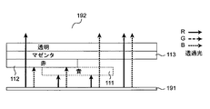
図24及び図25に示すように、表示フィルタ110−1は、第1実施形態にて説明した、青色の意匠パターンフィルタ111と、赤色の意匠パターンフィルタ112と、目隠しフィルタ113とを備え、さらに、第2実施形態にて特徴的構成部分である無彩色フィルタ115を備えている。尚、本第2実施形態においても拡散板114を付属している。   As shown in FIGS. 24 and 25, the display filter 110-1 includes the blue design pattern filter 111, the red design pattern filter 112, and the blindfold filter 113 described in the first embodiment. The achromatic filter 115 which is a characteristic component in the second embodiment is provided. Note that the diffusion plate 114 is also attached in the second embodiment.

無彩色フィルタ115は、意匠パターンフィルタ111,112、及び目隠しフィルタ113と同一形状にてなり、かつ重ねて配置され、目隠しフィルタ113よりも視認側192に配置される。
無彩色フィルタ115には、光源120が消灯状態で外周光194のみが表示フィルタ110−1に作用するとき、外周光194により可視となる表示意匠パターン115aが形成されている。本実施形態では、無彩色フィルタ115は、図25及び図26に示すように、目隠しフィルタ113を含む第1実施形態における表示フィルタ110の目隠しフィルタ113上に配置されることから、表示意匠パターン115aは、上記意匠パターン111a,112aと重なる位置に配置される。
The achromatic color filter 115 has the same shape as the design pattern filters 111 and 112 and the blindfold filter 113 and is arranged so as to overlap with each other, and is disposed closer to the viewing side 192 than the blindfold filter 113.
The achromatic color filter 115 is formed with a display design pattern 115a that is visible by the peripheral light 194 when only the peripheral light 194 acts on the display filter 110-1 with the light source 120 turned off. In the present embodiment, the achromatic color filter 115 is disposed on the blindfold filter 113 of the display filter 110 in the first embodiment including the blindfold filter 113 as shown in FIGS. 25 and 26, and therefore, the display design pattern 115a. Are arranged at positions overlapping the design patterns 111a and 112a.

無彩色フィルタ115は、例えば、透明又は半透明のシート材を基材とし、表示意匠パターン115a以外の素地部115bを、表示意匠パターン115a部分とは光反射率、光吸収率、及び光拡散度差の少なくとも一つが異なる材料にて印刷又は真空蒸着することで作製される。例えば、表示意匠パターン115a部分を光反射率が高い材料で、素地部115bを光吸収率が高い材料で形成する。   The achromatic color filter 115 is made of, for example, a transparent or translucent sheet material as a base material, and the base portion 115b other than the display design pattern 115a is different from the display design pattern 115a portion in terms of light reflectance, light absorption rate, and light diffusion rate. At least one of the differences is produced by printing or vacuum deposition with different materials. For example, the display design pattern 115a is formed of a material having a high light reflectance, and the base portion 115b is formed of a material having a high light absorption rate.

このように作製された無彩色フィルタ115では、外周光194が照射されたとき反射する部分は白く見え、光吸収が高い部分は黒く見える。よって、光源120が消灯状態であり外周光194のみが作用するとき、無彩色フィルタ115を有する表示フィルタ110−1は、第1実施形態で説明したように上記意匠パターン111b、112bを視認し難くするとともに、表示意匠パターン115a部分を素地部115bとは異なって視認可能とする。即ち、消灯時には、表示意匠パターン115aが表現される。   In the achromatic filter 115 manufactured in this way, when the peripheral light 194 is irradiated, the portion that reflects is white and the portion with high light absorption looks black. Therefore, when the light source 120 is turned off and only the peripheral light 194 acts, the display filter 110-1 having the achromatic filter 115 is difficult to visually recognize the design patterns 111b and 112b as described in the first embodiment. In addition, the display design pattern 115a can be visually recognized unlike the base portion 115b. That is, when the light is turned off, the display design pattern 115a is expressed.

又、光源120の発光時において、表示意匠パターン115aが邪魔をして意匠パターン111b、112bに表示ムラが発生するのを防止するため、表示意匠パターン115aと、素地部115bとの光透過率を同一又はほぼ同一にするのが好ましい。
上述のように、無彩色フィルタ115は、表示意匠パターン115a部分を光反射率が高い、例えば数%の反射率の材料で形成し、素地部115bを光吸収率が高い材料で形成している。しかしながら、表示意匠パターン115a部分の光反射は、外周光の照度に大きく左右される。このことは、屋内外で使用される例えば携帯電話等のモバイル機器に当該表示フィルタ110−1を採用する場合、表示意匠パターン115aの光反射率の決定を非常に難しくする。即ち、光源120が消灯しているとき、屋内における外周光のみで表示意匠パターン115a部分を表示させるために表示意匠パターン115a部分の光反射率を高くし過ぎると、光源120の点灯時に光源120の光により表示意匠パターン115a部分が表現されてしまうという問題が生じ、逆に、該問題を防止するため、また屋外における外周光に対応させて、表示意匠パターン115a部分の光反射率を低く設定し過ぎると、屋内では光源120の消灯時に表示意匠パターン115a部分が表現できない。したがって、実際には、表示意匠パターン115a部分の光反射率と、素地部115bの光吸収率と、表示意匠パターン115a部分及び素地部115bの光透過率とを、微妙に調整する必要がある。
Further, in order to prevent the display design pattern 115a from interfering with the display patterns 115b and 112b when the light source 120 emits light, the light transmittance between the display design pattern 115a and the base portion 115b is set. Preferably they are the same or nearly the same.
As described above, in the achromatic color filter 115, the display design pattern 115a is formed of a material having a high light reflectance, for example, a reflectance of several percent, and the base portion 115b is formed of a material having a high light absorption rate. . However, the light reflection of the display design pattern 115a is greatly influenced by the illuminance of the peripheral light. This makes it very difficult to determine the light reflectance of the display design pattern 115a when the display filter 110-1 is employed in a mobile device such as a cellular phone used indoors and outdoors. That is, when the light reflectance of the display design pattern 115a is excessively increased in order to display the display design pattern 115a only with the outside light indoors when the light source 120 is turned off, the light source 120 is turned on when the light source 120 is turned on. There is a problem that the display design pattern 115a portion is expressed by light, and conversely, in order to prevent this problem, the light reflectance of the display design pattern 115a portion is set to be low in correspondence with the ambient light outside. If it is too long, the display design pattern 115a portion cannot be expressed indoors when the light source 120 is turned off. Therefore, in practice, it is necessary to finely adjust the light reflectance of the display design pattern 115a portion, the light absorption rate of the base portion 115b, and the light transmittance of the display design pattern 115a portion and the base portion 115b.

上述の例では、無彩色フィルタ115は、意匠パターンフィルタ111,112、及び目隠しフィルタ113を有する表示フィルタ110とは別の部材にて形成したが、図27及び図28に示すように、目隠しフィルタに表示意匠パターン115aを形成することもできる。即ち、図27及び図28において、符号116にて示すものは、上述した目隠しフィルタ113と、無彩色フィルタ115との機能を併せ持つ目隠しフィルタである。当該目隠しフィルタ116の視認側192には、上記表示意匠パターン115aが形成されている。又、このような目隠しフィルタ116を有する表示フィルタについて符号110−2を符番し、該表示フィルタ110−2を備えた表示モジュールについて符号103を符番する。
このように構成した表示フィルタ110−2についても、上述の表示フィルタ110−1と同一の作用、効果を得ることができる。
In the above example, the achromatic filter 115 is formed of a member different from the display filter 110 having the design pattern filters 111 and 112 and the blindfold filter 113. However, as shown in FIGS. The display design pattern 115a can also be formed. That is, in FIG. 27 and FIG. 28, what is indicated by reference numeral 116 is a blindfold filter having the functions of the above-described blindfold filter 113 and the achromatic color filter 115. The display design pattern 115 a is formed on the viewing side 192 of the blindfold filter 116. Further, reference numeral 110-2 is assigned to a display filter having such a blindfold filter 116, and reference numeral 103 is assigned to a display module having the display filter 110-2.
The display filter 110-2 configured in this way can also obtain the same operations and effects as the display filter 110-1.

又、上述した表示フィルタ110−1、110−2では、表示意匠パターン115aは、意匠パターンフィルタ111,112における意匠パターン111b、112bとは異なる意匠パターンであるが、図29に示すように、例えば青色の意匠パターンフィルタ111に形成した意匠パターン111b−1と同一の形状及びサイズとすることもできる。表示意匠パターン115aを、意匠パターンフィルタ111における意匠パターン111b、又は意匠パターンフィルタ112における意匠パターン112bと同一にすることで、光源120からの光源光及び外周光により、表示意匠パターン115aの輝度を向上させることができる。   In the display filters 110-1 and 110-2 described above, the display design pattern 115a is a design pattern different from the design patterns 111b and 112b in the design pattern filters 111 and 112. As shown in FIG. It can also be set as the same shape and size as the design pattern 111b-1 formed in the blue design pattern filter 111. By making the display design pattern 115 a the same as the design pattern 111 b in the design pattern filter 111 or the design pattern 112 b in the design pattern filter 112, the luminance of the display design pattern 115 a is improved by the light source light and the peripheral light from the light source 120. Can be made.

又、上述した第2実施形態では、表示意匠パターン115aを有する無彩色フィルタ115は、目隠しフィルタ113よりも視認側192に配置しているが、例えば図30に示すように、目隠しフィルタ113よりも光源120側に配置することもできる。即ち、無彩色フィルタ115は、目隠しフィルタ113と意匠パターンフィルタ112との間、意匠パターンフィルタ112と意匠パターンフィルタ111との間、又は意匠パターンフィルタ111よりも光源120側に配置することができる。尚、図30は、無彩色フィルタ115を、目隠しフィルタ113と意匠パターンフィルタ112との間に配置した表示フィルタ110−3を図示している。   In the second embodiment described above, the achromatic color filter 115 having the display design pattern 115a is arranged on the visual recognition side 192 relative to the blindfold filter 113. For example, as shown in FIG. It can also be arranged on the light source 120 side. That is, the achromatic filter 115 can be disposed between the blindfold filter 113 and the design pattern filter 112, between the design pattern filter 112 and the design pattern filter 111, or closer to the light source 120 than the design pattern filter 111. 30 illustrates a display filter 110-3 in which the achromatic filter 115 is disposed between the blindfold filter 113 and the design pattern filter 112.

本発明は、同一の表示箇所に複数の意匠パターンを切り替えて表示するような表示フィルタ、及び該表示フィルタを有する表示モジュールに適用可能である。   The present invention can be applied to a display filter that switches and displays a plurality of design patterns at the same display location, and a display module having the display filter.

本発明の第1実施形態における表示モジュールの断面図である。It is sectional drawing of the display module in 1st Embodiment of this invention. 図1に示す表示モジュールに備わる表示フィルタを示す斜視図である。It is a perspective view which shows the display filter with which the display module shown in FIG. 1 is equipped. 図2に示す表示フィルタに備わる目隠しフィルタの一例の作用により意匠パターンが視認し難くなることを説明するための図である。It is a figure for demonstrating that it becomes difficult to visually recognize a design pattern by the effect | action of an example of the blindfold filter with which the display filter shown in FIG. 2 is equipped. 図2に示す表示フィルタに備わる目隠しフィルタの他の例による作用により意匠パターンが視認し難くなることを説明するための図である。It is a figure for demonstrating that it becomes difficult to visually recognize a design pattern by the effect | action by the other example of the blindfold filter with which the display filter shown in FIG. 2 is equipped. 図2に示す表示フィルタに含まれる意匠パターンが視認される原理を説明するための図である。It is a figure for demonstrating the principle by which the design pattern contained in the display filter shown in FIG. 2 is visually recognized. 図2に示す目隠しフィルタにより意匠パターンが視認し難くなることを説明するために目隠しフィルタが存在しない場合を説明するための図である。It is a figure for demonstrating the case where a blindfold filter does not exist in order to demonstrate that a design pattern becomes difficult to visually recognize with the blindfold filter shown in FIG. 図2に示す目隠しフィルタにより意匠パターンが視認し難くなることを説明するための図である。It is a figure for demonstrating that a design pattern becomes difficult to visually recognize with the blindfold filter shown in FIG. 図2に示す目隠しフィルタの存在の有無に関係なく意匠パターンを視認可能であることを説明するため目隠しフィルタが存在しない場合を説明するための図である。It is a figure for demonstrating the case where a blindfold filter does not exist in order to demonstrate that a design pattern is visually recognizable irrespective of the presence or absence of the blindfold filter shown in FIG. 図2に示す目隠しフィルタの存在の有無に関係なく意匠パターンを視認可能であることを説明するため目隠しフィルタを設けた場合を説明するための図である。It is a figure for demonstrating the case where the blindfold filter is provided in order to demonstrate that the design pattern can be visually recognized irrespective of the presence or absence of the blindfold filter shown in FIG. 図2に示す表示フィルタに含まれる意匠パターンを重ねず別々に配置した状態を示す図である。It is a figure which shows the state which has arrange | positioned separately the design pattern contained in the display filter shown in FIG. 2 without overlapping. 図1に示す表示モジュールに備わる光源に使用可能な各色のLEDにおける光源光の波長域を示すグラフである。It is a graph which shows the wavelength range of the light source light in LED of each color which can be used for the light source with which the display module shown in FIG. 1 is equipped. 図1に示す表示モジュールに備わる赤色光源の発光特性、及び青色の意匠パターンフィルタの光透過特性を示すグラフである。It is a graph which shows the light transmission characteristic of the red light source with which the display module shown in FIG. 1 is equipped, and the light transmission characteristic of a blue design pattern filter. 図1に示す表示モジュールに備わる青色光源の発光特性、及び赤色の意匠パターンフィルタの光透過特性を示すグラフである。2 is a graph showing light emission characteristics of a blue light source and light transmission characteristics of a red design pattern filter provided in the display module shown in FIG. 1. 図1に示す表示モジュールに備わる青色の意匠パターンフィルタの光透過特性及び光反射特性を示すグラフである。It is a graph which shows the light transmission characteristic and light reflection characteristic of the blue design pattern filter with which the display module shown in FIG. 1 is equipped. 図1に示す表示モジュールに備わる赤色の意匠パターンフィルタの光透過特性及び光反射特性を示すグラフである。It is a graph which shows the light transmission characteristic and light reflection characteristic of the red design pattern filter with which the display module shown in FIG. 1 is equipped. 図1に示す表示モジュールに備わる赤色及び青色の光源の発光特性、青色及び赤色の意匠パターンフィルタの光透過特性、並びに目隠しフィルタの光透過特性を示すグラフである。2 is a graph showing light emission characteristics of red and blue light sources, light transmission characteristics of a blue and red design pattern filter, and light transmission characteristics of a blindfold filter included in the display module shown in FIG. 1. 図1に示す表示モジュールに備わる目隠しフィルタの光透過特性及び光反射特性を示すグラフである。2 is a graph showing light transmission characteristics and light reflection characteristics of a blindfold filter provided in the display module shown in FIG. 1. 図1に示す表示モジュールに備わる目隠しフィルタの理想に近い光透過特性の一例を示す図である。It is a figure which shows an example of the light transmission characteristic close | similar to the ideal of the blindfold filter with which the display module shown in FIG. 1 is equipped. 図1に示す表示モジュールの具体的構成例の断面図である。It is sectional drawing of the specific structural example of the display module shown in FIG. 図1に示す表示モジュールの具体的構成例の断面図である。It is sectional drawing of the specific structural example of the display module shown in FIG. 図1に示す表示モジュールの具体的構成例の断面図である。It is sectional drawing of the specific structural example of the display module shown in FIG. 図1に示す表示モジュールの具体的構成例の断面図である。It is sectional drawing of the specific structural example of the display module shown in FIG. 図1に示す表示モジュールの具体的構成例の断面図である。It is sectional drawing of the specific structural example of the display module shown in FIG. 本発明の第2実施形態における表示モジュールの断面図である。It is sectional drawing of the display module in 2nd Embodiment of this invention. 図24に示す表示モジュールに備わる表示フィルタを示す斜視図である。FIG. 25 is a perspective view showing a display filter provided in the display module shown in FIG. 24. 図24に示す表示フィルタに備わる無彩色フィルタの作用を説明するための図である。It is a figure for demonstrating the effect | action of the achromatic filter with which the display filter shown in FIG. 24 is equipped. 図24に示す表示フィルタの他の例を備えた表示モジュールの断面図である。FIG. 25 is a cross-sectional view of a display module including another example of the display filter shown in FIG. 24. 図27に示す他の例における表示フィルタの斜視図である。It is a perspective view of the display filter in the other example shown in FIG. 図24及び図27に示す表示フィルタにおいて、無彩色フィルタに形成した表示意匠パターンを意匠パターンと同一にした場合を示す斜視図である。It is a perspective view which shows the case where the display design pattern formed in the achromatic color filter is made the same as a design pattern in the display filter shown in FIG.24 and FIG.27. 図24に示す表示フィルタの変形例であって、無彩色フィルタを、目隠しフィルタと意匠パターンフィルタとの間に配置した場合を示す斜視図である。FIG. 25 is a perspective view showing a modification of the display filter shown in FIG. 24 and showing a case where an achromatic color filter is disposed between a blindfold filter and a design pattern filter. 従来の表示モジュールの断面図である。It is sectional drawing of the conventional display module. 従来の表示モジュールの動作を説明するための図である。It is a figure for demonstrating operation | movement of the conventional display module.

符号の説明Explanation of symbols

101,102,103…表示モジュール、110…表示フィルタ、
111…青色の意匠パターンフィルタ、111b…意匠パターン、
112…赤色の意匠パターンフィルタ、112b…意匠パターン、
113…目隠しフィルタ、115…無彩色フィルタ、
115a…表示意匠パターン、116…無彩色フィルタ、
120…光源、121…青色光源、121a…青色光源光、
122…赤色光源、122a…赤色光源光、
193…光源駆動回路部。
101, 102, 103 ... display module, 110 ... display filter,
111 ... Blue design pattern filter, 111b ... Design pattern,
112 ... red design pattern filter, 112b ... design pattern,
113 ... Blindfold filter, 115 ... Achromatic filter,
115a: Display design pattern, 116: Achromatic filter,
120 ... light source, 121 ... blue light source, 121a ... blue light source light,
122 ... Red light source, 122a ... Red light source light,
193: a light source driving circuit unit.

Claims (13)

互いに重ね合わされる複数の意匠パターンフィルタ(111、112)と、
上記複数の意匠パターンフィルタを間に挟み光源とは反対側に位置する視認側(192)に上記複数の意匠パターンフィルタと重ね合わされ配置される目隠しフィルタ(113)とを備え、
それぞれの上記意匠パターンフィルタは、特定波長域の光源光(121a,122a)を透過する意匠パターン(111b、112b)を有し上記意匠パターン外の素地部(111a、112a)では上記特定波長域の光源光を吸収する吸収型のフィルタであり、互いに異なる意匠パターンを有し、かつそれぞれの上記特定波長域の光源光を吸収してそれぞれ異なる上記意匠パターンを表示し、
上記目隠しフィルタは、上記光源光が消灯状態で外周光により複数の上記意匠パターンが可視となるのを防止するフィルタであり、それぞれの上記意匠パターンを透過するそれぞれの上記特定波長域の光源光を透過し、かつそれぞれの上記特定波長域外の波長域の光を吸収する、
ことを特徴とする表示フィルタ。
A plurality of design pattern filters (111, 112) superimposed on each other;
A blindfold filter (113) disposed on the viewing side (192) located on the opposite side of the light source with the plurality of design pattern filters interposed therebetween and overlaid with the plurality of design pattern filters,
Each of the design pattern filters has a design pattern (111b, 112b) that transmits light source light (121a, 122a) in a specific wavelength range, and the substrate portion (111a, 112a) outside the design pattern has a specific wavelength range. It is an absorption type filter that absorbs light source light, has design patterns different from each other, and absorbs light source light in each of the specific wavelength ranges to display the different design patterns.
The blindfold filter is a filter that prevents the plurality of design patterns from becoming visible due to ambient light when the light source light is turned off, and the light sources in the specific wavelength range that pass through the design patterns. Transmits light and absorbs light in a wavelength region outside the specific wavelength region.
A display filter characterized by that.
それぞれの上記意匠パターンフィルタ及び上記目隠しフィルタは、一枚のシート材として一体的に形成される、請求項1記載の表示フィルタ。   The display filter according to claim 1, wherein each of the design pattern filter and the blindfold filter is integrally formed as one sheet material. それぞれの上記意匠パターンフィルタ及び上記目隠しフィルタは、一枚のシート材にインク印刷にて一体的に形成される、請求項2記載の表示フィルタ。   The display filter according to claim 2, wherein each of the design pattern filter and the blind filter is integrally formed on one sheet material by ink printing. 上記目隠しフィルタよりも上記視認側又は光源側に配置され、上記光源光が消灯状態であり上記外周光により可視となる表示意匠パターン(115a)を有する無彩色フィルタ(115)をさらに備えた、請求項1から3のいずれかに記載の表示フィルタ。   An achromatic color filter (115) further comprising a display design pattern (115a) disposed on the viewing side or the light source side of the blindfold filter and having the light source light turned off and visible by the peripheral light. Item 4. The display filter according to any one of Items 1 to 3. 上記表示意匠パターンは、上記目隠しフィルタへのインク印刷により形成される、請求項4記載の表示フィルタ。   The display filter according to claim 4, wherein the display design pattern is formed by ink printing on the blindfold filter. 上記無彩色フィルタにおける上記表示意匠パターンは、透明又は半透明のシート材へインク印刷又は真空蒸着にて形成される、請求項4記載の表示フィルタ。   The display filter according to claim 4, wherein the display design pattern in the achromatic color filter is formed by ink printing or vacuum deposition on a transparent or translucent sheet material. 上記無彩色フィルタにおける上記表示意匠パターンは、上記意匠パターンフィルタにおけるいずれかの意匠パターンと同一パターンである、請求項4から6のいずれかに記載の表示フィルタ。   The display filter according to claim 4, wherein the display design pattern in the achromatic color filter is the same pattern as any one of the design patterns in the design pattern filter. それぞれの上記意匠パターンフィルタが吸収する上記光源光の上記特定波長域は、それぞれ独立しており重複しない、請求項1から7のいずれかに記載の表示フィルタ。   The display filter according to claim 1, wherein the specific wavelength ranges of the light source light absorbed by the design pattern filters are independent and do not overlap each other. それぞれの上記意匠パターンフィルタが吸収する上記光源光の上記特定波長域は、境界域で重複する、請求項1から7のいずれかに記載の表示フィルタ。   The display filter according to claim 1, wherein the specific wavelength region of the light source light absorbed by each of the design pattern filters overlaps in a boundary region. それぞれの上記意匠パターンフィルタに形成された各意匠パターンは、同一箇所に重複して配置されている、請求項1から9のいずれかに記載の表示フィルタ。   The display filter according to any one of claims 1 to 9, wherein each design pattern formed on each of the design pattern filters is arranged in duplicate at the same location. それぞれの上記意匠パターンフィルタに形成された各意匠パターンは、互いに独立した位置に重複せずに配置されている、請求項1から9のいずれかに記載の表示フィルタ。   The display filter according to any one of claims 1 to 9, wherein each design pattern formed on each of the design pattern filters is arranged in an independent position without overlapping. 請求項1から11のいずれかに記載の表示フィルタ(110,110−1、110−2)と、
上記表示フィルタに含まれるそれぞれの意匠パターンフィルタ(111,112)が吸収する特定波長域の光源光を発する光源(120)と、
を備えたことを特徴とする表示モジュール。
A display filter (110, 110-1, 110-2) according to any of claims 1 to 11,
A light source (120) that emits light of a specific wavelength region that is absorbed by each of the design pattern filters (111, 112) included in the display filter;
A display module characterized by comprising:
上記光源は複数個設けられ、各光源は、それぞれの意匠パターンフィルタにおいて吸収されるそれぞれの特定波長域に対応した光源光をそれぞれ発し、
発光させる上記光源を切り替え、発光した光源からの光源光に対応する意匠パターンフィルタにおける意匠パターンを表示させる切替スイッチ(193)をさらに備えた、請求項12記載の表示モジュール。
A plurality of the light sources are provided, and each light source emits light source light corresponding to each specific wavelength region absorbed in each design pattern filter,
The display module according to claim 12, further comprising a changeover switch (193) for switching the light source to emit light and displaying a design pattern in a design pattern filter corresponding to light source light from the emitted light source.
JP2007264375A 2007-10-10 2007-10-10 Display filter and display module having display filter Pending JP2009092993A (en)

Priority Applications (3)

Application Number Priority Date Filing Date Title
JP2007264375A JP2009092993A (en) 2007-10-10 2007-10-10 Display filter and display module having display filter
KR1020080076237A KR100989240B1 (en) 2007-10-10 2008-08-05 Display filter and display module having the same
US12/246,698 US20090097145A1 (en) 2007-10-10 2008-10-07 Display filter and display module provided therewith

Applications Claiming Priority (1)

Application Number Priority Date Filing Date Title
JP2007264375A JP2009092993A (en) 2007-10-10 2007-10-10 Display filter and display module having display filter

Publications (1)

Publication Number Publication Date
JP2009092993A true JP2009092993A (en) 2009-04-30

Family

ID=40533940

Family Applications (1)

Application Number Title Priority Date Filing Date
JP2007264375A Pending JP2009092993A (en) 2007-10-10 2007-10-10 Display filter and display module having display filter

Country Status (3)

Country Link
US (1) US20090097145A1 (en)
JP (1) JP2009092993A (en)
KR (1) KR100989240B1 (en)

Cited By (6)

* Cited by examiner, † Cited by third party
Publication number Priority date Publication date Assignee Title
WO2012090589A1 (en) * 2010-12-28 2012-07-05 株式会社Jvcケンウッド Lighting device
JP2012159678A (en) * 2011-01-31 2012-08-23 Tokai Kogaku Kk Optical display device
KR101244053B1 (en) 2011-06-30 2013-03-18 대성전기공업 주식회사 Power window switching module
WO2014129577A1 (en) * 2013-02-22 2014-08-28 アルプス電気株式会社 Display device
WO2019225636A1 (en) * 2018-05-22 2019-11-28 三菱ケミカル株式会社 Color display device, vehicle interior/exterior member, lamp for panel light, signboard for display and vehicle
WO2023191087A1 (en) * 2022-03-31 2023-10-05 大日本印刷株式会社 Decorative member, resin molded product and display device with decoration

Families Citing this family (6)

* Cited by examiner, † Cited by third party
Publication number Priority date Publication date Assignee Title
KR101271380B1 (en) * 2011-12-15 2013-06-04 대성전기공업 주식회사 Variable sysmbol displaying switch unit and method for controlling the same
KR101271335B1 (en) * 2011-12-29 2013-06-05 대성전기공업 주식회사 Variable sysmbol displaying switch unit and method for controlling the same
EP3723073A1 (en) 2019-03-21 2020-10-14 Panasonic Intellectual Property Management Co., Ltd. Information display device
EP3789990A1 (en) 2019-09-05 2021-03-10 Panasonic Intellectual Property Management Co., Ltd. Information display terminal
CN110780746B (en) * 2019-10-09 2021-08-24 维沃移动通信有限公司 Key structure, key control method and electronic equipment
EP3828872B1 (en) * 2019-11-28 2023-11-01 Panasonic Intellectual Property Management Co., Ltd. Information display device

Family Cites Families (9)

* Cited by examiner, † Cited by third party
Publication number Priority date Publication date Assignee Title
US4354739A (en) * 1980-09-03 1982-10-19 Optical Coating Laboratory, Inc. Color absorption-type filter and method of making
JP3160166B2 (en) * 1994-11-02 2001-04-23 矢崎総業株式会社 Multiple display
DE19935386A1 (en) * 1999-07-29 2001-02-01 Mannesmann Vdo Ag Display with an X-ray display field
US20050253505A1 (en) * 2002-03-06 2005-11-17 Braak Rogier J Electronic display device
JP2005257938A (en) * 2004-03-10 2005-09-22 Calsonic Kansei Corp Variable display structure
JP2006337772A (en) * 2005-06-02 2006-12-14 Calsonic Kansei Corp Variable display structure
US7581342B2 (en) * 2005-08-24 2009-09-01 Calsonic Kansei Corporation Display device
JP4993985B2 (en) * 2006-03-30 2012-08-08 カルソニックカンセイ株式会社 Variable display structure
TWI344661B (en) * 2007-09-12 2011-07-01 Wistron Corp Keypad device and related input device for an electronic device

Cited By (11)

* Cited by examiner, † Cited by third party
Publication number Priority date Publication date Assignee Title
WO2012090589A1 (en) * 2010-12-28 2012-07-05 株式会社Jvcケンウッド Lighting device
JP2012159678A (en) * 2011-01-31 2012-08-23 Tokai Kogaku Kk Optical display device
KR101244053B1 (en) 2011-06-30 2013-03-18 대성전기공업 주식회사 Power window switching module
WO2014129577A1 (en) * 2013-02-22 2014-08-28 アルプス電気株式会社 Display device
JPWO2014129577A1 (en) * 2013-02-22 2017-02-02 アルプス電気株式会社 Display device
WO2019225636A1 (en) * 2018-05-22 2019-11-28 三菱ケミカル株式会社 Color display device, vehicle interior/exterior member, lamp for panel light, signboard for display and vehicle
JPWO2019225636A1 (en) * 2018-05-22 2020-05-28 三菱ケミカル株式会社 Color display devices, vehicle interior/exterior members, lamps for lighting, display signs, and vehicles
CN112166467A (en) * 2018-05-22 2021-01-01 三菱化学株式会社 Color display device, vehicle interior/exterior member, lamp for illumination lamp, display signboard, and vehicle
JP7052808B2 (en) 2018-05-22 2022-04-12 三菱ケミカル株式会社 Color display devices, vehicle interior / exterior members, lighting lamps, display signs and vehicles
US11623518B2 (en) 2018-05-22 2023-04-11 Mitsubishi Chemical Corporation Color display device, vehicle interior/exterior member, lamp for panel light, signboard for display and vehicle
WO2023191087A1 (en) * 2022-03-31 2023-10-05 大日本印刷株式会社 Decorative member, resin molded product and display device with decoration

Also Published As

Publication number Publication date
KR20090037289A (en) 2009-04-15
KR100989240B1 (en) 2010-10-20
US20090097145A1 (en) 2009-04-16

Similar Documents

Publication Publication Date Title
JP2009092993A (en) Display filter and display module having display filter
TWI598918B (en) Illuminated keyboard
JP2007280677A5 (en)
JP6206870B2 (en) Optical display device
JP5178427B2 (en) Display device and electronic apparatus
JP2010145477A (en) Light emitting display device
JP6085779B2 (en) Optical structure
KR101345664B1 (en) Mobile terminal
JP4712476B2 (en) Variable display structure
US8740399B2 (en) Touch type lamp switch
JP2009128375A (en) Display
JP2019076248A (en) Operation unit and game machine
JP2001345912A (en) Portable terminal equipment
JP4056608B2 (en) Surface illuminated display device
JP2022090750A (en) Display unit and display board
EP3696800A1 (en) Display device
CN217386614U (en) Display device, human-computer interaction system and household appliance
JP2006337772A (en) Variable display structure
JP2023109735A (en) Display device, display method, human machine interaction system, and home appliances
KR100801973B1 (en) El sheet for multi-light emitting and el keypad using the same
JP2009283174A (en) Illumination structure equipped with light guide layer
JP2007073301A (en) Key panel with illumination
JPH11202806A (en) Display unit
JP2022090751A (en) Display unit and display board
JP2010134151A (en) Light emitting display device

Legal Events

Date Code Title Description
A621 Written request for application examination

Free format text: JAPANESE INTERMEDIATE CODE: A621

Effective date: 20100804

A977 Report on retrieval

Free format text: JAPANESE INTERMEDIATE CODE: A971007

Effective date: 20120312

A131 Notification of reasons for refusal

Free format text: JAPANESE INTERMEDIATE CODE: A131

Effective date: 20120626

A02 Decision of refusal

Free format text: JAPANESE INTERMEDIATE CODE: A02

Effective date: 20121106