JP2009072012A - Axial gap type rotary electric machine - Google Patents
Axial gap type rotary electric machine Download PDFInfo
- Publication number
- JP2009072012A JP2009072012A JP2007239268A JP2007239268A JP2009072012A JP 2009072012 A JP2009072012 A JP 2009072012A JP 2007239268 A JP2007239268 A JP 2007239268A JP 2007239268 A JP2007239268 A JP 2007239268A JP 2009072012 A JP2009072012 A JP 2009072012A
- Authority
- JP
- Japan
- Prior art keywords
- rotor
- gap type
- axial gap
- type rotating
- rotating electrical
- Prior art date
- Legal status (The legal status is an assumption and is not a legal conclusion. Google has not performed a legal analysis and makes no representation as to the accuracy of the status listed.)
- Granted
Links
Images


Classifications
-
- H—ELECTRICITY
- H02—GENERATION; CONVERSION OR DISTRIBUTION OF ELECTRIC POWER
- H02K—DYNAMO-ELECTRIC MACHINES
- H02K1/00—Details of the magnetic circuit
- H02K1/06—Details of the magnetic circuit characterised by the shape, form or construction
- H02K1/22—Rotating parts of the magnetic circuit
- H02K1/28—Means for mounting or fastening rotating magnetic parts on to, or to, the rotor structures
- H02K1/30—Means for mounting or fastening rotating magnetic parts on to, or to, the rotor structures using intermediate parts, e.g. spiders
-
- H—ELECTRICITY
- H02—GENERATION; CONVERSION OR DISTRIBUTION OF ELECTRIC POWER
- H02K—DYNAMO-ELECTRIC MACHINES
- H02K1/00—Details of the magnetic circuit
- H02K1/06—Details of the magnetic circuit characterised by the shape, form or construction
- H02K1/22—Rotating parts of the magnetic circuit
- H02K1/27—Rotor cores with permanent magnets
-
- H—ELECTRICITY
- H02—GENERATION; CONVERSION OR DISTRIBUTION OF ELECTRIC POWER
- H02K—DYNAMO-ELECTRIC MACHINES
- H02K21/00—Synchronous motors having permanent magnets; Synchronous generators having permanent magnets
- H02K21/12—Synchronous motors having permanent magnets; Synchronous generators having permanent magnets with stationary armatures and rotating magnets
- H02K21/24—Synchronous motors having permanent magnets; Synchronous generators having permanent magnets with stationary armatures and rotating magnets with magnets axially facing the armatures, e.g. hub-type cycle dynamos
Abstract
Description
本発明は、ステータと、円盤形状のロータとを軸線方向に対向配置したアキシャルギャップ型回転電機が、面振動により共振することを防止する技術に関する。 The present invention relates to a technique for preventing an axial gap type rotating electrical machine in which a stator and a disk-shaped rotor are arranged opposite to each other in the axial direction from resonating due to surface vibration.
単位時間における円運動回数である回転電機のロータ回転速度が、単位時間における波形運動回数である回転電機の固有振動数と符合する場合、ロータが加振力を回転電機に与えることになって、回転電機が共振するという問題が知られている。
そこで従来、回転電機の共振を防止する技術として、例えば特許文献1に記載のごときものが知られている。
特許文献1に記載の回転電機は、回転電機のフレームに熱交換器を取り付ける取付剛性調整ボルトの締め付け力を調整することにより取り付け剛性を適宜に変化させて、これにより回転電機全体の固有振動数を変化させるというものである。特許文献1に記載の技術は、回転電機の据え付け剛性が工場出荷時の評価と異なっていても、共振現象を回避して静粛な運転を図るものである。
Therefore, conventionally, as a technique for preventing the resonance of the rotating electrical machine, for example, a technique described in
The rotating electrical machine described in
しかし、上記従来のような回転電機によっても、回転電機のロータ自身の固有振動数を変化させることはできない。特に、ロータが円盤形状であるアキシャルギャップ型回転電機にあっては、ロータ厚みが小さく、当該ロータ厚みと比較してロータ半径が大きいことからロータの剛性が低く、軸線方向に直角な仮想平面に対してロータが撓んだり歪んだりする振動モードである面振動が生じやすい。
ロータ回転速度がロータ自身の固有振動数と符合した場合、ロータ自身の共振が無視し得ないほど大きくなって、回転電機の静粛な運転を妨げてしまう。
However, the natural frequency of the rotor itself of the rotating electrical machine cannot be changed even by the conventional rotating electrical machine. In particular, in an axial gap type rotating electrical machine in which the rotor has a disk shape, the rotor thickness is small and the rotor radius is large compared to the rotor thickness, so that the rigidity of the rotor is low, and the virtual plane is perpendicular to the axial direction. On the other hand, surface vibration, which is a vibration mode in which the rotor is bent or distorted, is likely to occur.
When the rotor rotational speed matches the natural frequency of the rotor itself, the resonance of the rotor itself becomes so large that it cannot be ignored, which hinders quiet operation of the rotating electrical machine.
なお、ロータにリブなどの補強部材を設けることが考えられるが、このような補強部材は、ロータを駆動する電磁力の磁気回路としてなんら有用でなく、むしろ、ロータ自身の体積が大きくなって、前記磁気回路を構成する磁束の密度を弱めてしまい、ロータ出力トルクが減少する。 Although it is conceivable to provide a reinforcing member such as a rib on the rotor, such a reinforcing member is not useful at all as a magnetic circuit of electromagnetic force for driving the rotor, but rather the volume of the rotor itself is increased, The density of the magnetic flux constituting the magnetic circuit is weakened, and the rotor output torque is reduced.
本発明は、上述の実情に鑑み、別途の補強部材をロータに設けることなく、ロータの共振を効果的に防ぐことができる技術を提案するものである。 In view of the above circumstances, the present invention proposes a technique that can effectively prevent resonance of a rotor without providing a separate reinforcing member on the rotor.
この目的のため本発明によるアキシャルギャップ型回転電機は、請求項1に記載のごとく、
ステータと、円盤形状のロータとを軸線方向に対向配置し、前記ステータと前記ロータとの間で発生する電磁力で前記ロータを駆動するアキシャルギャップ型の回転電機において、
前記ロータと該ロータに結合する出力軸との結合状態を変化させることにより、前記ロータが面振動により共振する固有振動数を前記ロータの回転速度から離隔するよう構成したことを特徴としたものである。
For this purpose, an axial gap type rotating electrical machine according to the present invention is as described in
In an axial gap type rotating electrical machine in which a stator and a disk-shaped rotor are arranged opposite to each other in the axial direction, and the rotor is driven by electromagnetic force generated between the stator and the rotor,
By changing the coupling state between the rotor and the output shaft coupled to the rotor, the natural frequency at which the rotor resonates due to surface vibration is separated from the rotational speed of the rotor. is there.
かかる本発明の構成によれば、ロータと該ロータに結合する出力軸との結合状態を変化させることにより、前記ロータが面振動により共振する固有振動数を前記ロータの回転速度から離隔するよう構成したことから、回転電機の運転中にロータ自身の共振を防止して静粛な運転が可能になる。 According to such a configuration of the present invention, by changing the coupling state of the rotor and the output shaft coupled to the rotor, the natural frequency at which the rotor resonates due to surface vibration is separated from the rotational speed of the rotor. As a result, the rotor itself can be prevented from resonating during the operation of the rotating electrical machine, and a quiet operation can be performed.
以下、本発明の実施の形態を、図面に示す実施例に基づき詳細に説明する。 Hereinafter, embodiments of the present invention will be described in detail based on examples shown in the drawings.
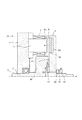
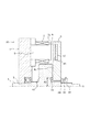
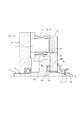
図1〜図3は本発明の第1実施例になるアキシャルギャップ型回転電機の構造を概略示す縦断面図である。 1 to 3 are longitudinal sectional views schematically showing the structure of an axial gap type rotating electrical machine according to a first embodiment of the present invention.
アキシャルギャップ型回転電機11のステータ1は、ステータコア2とステータ鉄心5と電機子巻線7とを具える。
強磁性体材料からなるステータコア2は円環状であり、ステータコア2の外周縁でモータケース8に支持固定される。またステータコア1の中央部には、中心孔3を設け、出力軸4を貫通させる。この出力軸4は中心孔3に設けた軸受で回動自在に支持される。ステータコア2のうち中心孔3より外径側の部位には、複数のステータ鉄心5を周方向に等間隔となるよう配置する。積層鋼板からなるステータ鉄心5は、ステータコア2から出力軸4の軸線O方向に突出し、先端5sが拡幅してロータ6と対向する。それぞれのステータコア5の軸線O方向中程には、電機子巻線7を巻回する。
The
The stator core 2 made of a ferromagnetic material has an annular shape and is supported and fixed to the
ロータ6は円盤状であり、エアギャップ9を介して上述したステータ鉄心先端5sと向き合うロータ6前面には複数の永久磁石10を周方向に等間隔となるよう配置する。ロータ6の内部には、バックヨーク12を埋設し、バックヨーク12を永久磁石10に貼り合わせる。永久磁石10は軸線O方向に着磁され、バックヨーク12は磁気回路を通す。ステータ1の電機子巻線7を流れる交流電流は回転磁界を発生させて、永久磁石10の磁束と共に磁気回路を形成する。この磁気回路は、ステータ1と、永久磁石10を具えるロータ6との間で電磁力を発生させて、ロータ6を同期モータとして回転させる。
The
ロータ6の中央に前述の出力軸4を貫通する。この出力軸4はスプラインによりロータ6と相対回転不能に係合して、ロータ6の回転を取り出す。ステータ鉄心5と軸線O方向で同じ位置には、出力軸4の中程を拡径して大径部4dを形成する。大径部4dは、ロータ6側で軸線Oに直角な環状端面4tを具える。環状端面4tの内径側には、軸線Oを中心とする環状のストッパ13を取り付ける。ストッパ13は、ロータ6前面と接合して、ロータ6の軸線方向位置を規定する。
The
ストッパ13は、テーパに形成され、ロータ6前面と出力軸4のストッパ13とが接合する接合面は、図1に示すように軸線O方向に突出したテーパと、このテーパを受け止める面の組合せになる。ストッパ13は、金属類の中でもヤング率の高い軽金属あるいはゴム類乃至樹脂類の中でもヤング率の低い硬質ゴム乃至硬質樹脂からなり、軸線O方向のスラストが生じると、僅かに変形する。そうすると、上述した接合面の接合面積が変化する。
The
ロータ6から見てストッパ13と反対側には、出力軸4に通された環状のカラー14と、菊ワッシャ15と、菊ワッシャ15によって緩まないよう出力軸4に螺合するロックナット16とを軸線O方向に順次配設する。カラー14はロータ6背面が出力軸4から抜け出ることを防止する。上述および図1に示すようにロータ6は前面および背面から軸線O方向位置を規定されて、軸線O方向にガタツキ無く出力軸Oと結合する。
An
次に第1実施例のアキシャルギャップ型回転電機11の作用について説明する。
ステータ1とロータ6との間で磁気回路による電磁力が発生してロータ6が回転するが、この電磁力としてステータ1とロータ6との間には吸引力が発生する。ロータ6から見てステータ1と出力軸大径部4dとが同じ前面側にあることから、電磁力の軸線O方向成分になる吸引力が、大径部4dとロータ6との間に介在するストッパ13にスラストを与える。
Next, the operation of the axial gap type rotating
An electromagnetic force generated by a magnetic circuit is generated between the
この吸引力が少なく、ストッパ13を押圧する軸線O方向のスラストが少ない場合にはストッパ13が殆ど変形しないことから、ストッパ13とロータ6との接合面の半径は図1に示すようにR1となる。
When the suction force is small and the thrust in the direction of the axis O pressing the
この吸引力が図1に示す場合よりも大きいとき、図2に細い矢で示す電磁力の軸線O方向成分がロータ6を引き寄せる。そうするとスラストによりストッパ13が変形し、テーパが少なくなるとともにストッパ13とロータ6との接合面の半径が大きくなって図2に示すようにR2となる(R1<R2)。
When this attraction force is larger than the case shown in FIG. 1, the axial O direction component of the electromagnetic force indicated by a thin arrow in FIG. 2 attracts the
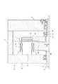
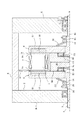
この吸引力が図2に示す場合よりもさらに大きいとき、図3に太い矢で示す電磁力の軸線O方向成分がロータ6を引き寄せる。そうするとスラストによりストッパ13がさらに変形し、テーパがなくなるとともにストッパ13とロータ6との接合面の半径が大きくなって図3に示すようにR3となる(R1<R2<R3)。この場合、ストッパ13よりも外径側にある大径部4dの環状端面4tが、ロータ6に接合する。環状端面4tおよびロータ6は、ストッパ6よりもヤング率が小さい鋼なので、ロータ6の支持剛性が最も大きくなる。
When this attractive force is larger than the case shown in FIG. 2, the axial force O direction component of the electromagnetic force indicated by the thick arrow in FIG. 3 attracts the
このように電磁力の軸線O方向成分によって出力軸4とロータ6との接合面の半径を、R1、R2、R3と連続的に変化させて、ロータ6が面振動により共振する固有振動数を変化させる。図3に示す状態から吸引力を減少させると接合面の半径がR3から減少し、図1および図2に示す状態に戻る。
In this way, the natural frequency at which the
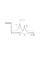
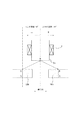
図4(a)は第1実施例におけるロータ6の面振動の振幅とロータ回転速度との関係を示すグラフである。接合面の半径がR1のとき、ロータ6の面振動の振幅が最も大きくなる固有振動数はfR1である。つまりロータ回転速度がfR1のとき、ロータ6の面振動が最も大きくなる。なお固有振動数もロータ回転速度も単位時間における運動であるため、双方とも図4(a)の横軸に示す。
FIG. 4A is a graph showing the relationship between the amplitude of the surface vibration of the
接合面の半径がR3(>R1)のとき、ロータ6の面振動の振幅が最も大きくなる固有振動数はfR3(>fR1)である。接合面の半径が大きいほど、接合面積が大きくなり、ロータ6の支持剛性が高くなるため、固有振動数が大きくなる。
When the radius of the joint surface is R3 (> R1), the natural frequency at which the amplitude of the surface vibration of the
第1実施例では、図4(a)に矢で示すように、接合面の半径をR1とR3との間で変化させることで、ロータ6の面振動による固有振動数を変化させ、ロータ6の回転速度から離隔する。例えば、ロータ回転速度がfR3のときは、接合面半径をR1として、ロータ固有振動数をfR3から離隔する。また、ロータ回転速度がfR1のときは、接合面半径をR3として、ロータ固有振動数をfR1から離隔する。これにより、ロータ6の面振動の共振を防止することができ、静粛な運転が可能になる。
In the first embodiment, as shown by an arrow in FIG. 4A, the natural frequency due to the surface vibration of the
上述した図4(a)に示した第1実施例のロータ6の固有振動数につき、図4(b)のマップに改めて示す。図4(b)の横軸は上述した接合部半径を2倍した結合部直径である。また縦軸は面振動により共振するロータ6の共振回転速度であり、図4(a)に示した固有振動数と同じである。図4(b)に示すように、結合部直径が大きくなれば共振回転速度も大きくなる。第1実施例では結合部直径を変化させて、ロータ6の共振回転速度を実際の回転速度から離隔することにより、ロータ6の面振動の共振を防止することができ、静粛な運転が可能になる。
The natural frequency of the
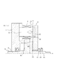
図5〜図7は本発明の第2実施例になるアキシャルギャップ型回転電機の構造を概略示す縦断面図である。図5は接合面半径が小さい状態(=R1)を表す。図6は接合面半径が図5の状態より大きい状態(=R2)を表す。また図7は接合面半径が図6の状態より大きい状態(=R4)を表す。この第2実施例の基本構成は、上述した第1実施例と共通するため、同一部材については、共通する符号を付して説明を省略し、異なる構成について説明する。 5 to 7 are longitudinal sectional views schematically showing the structure of an axial gap type rotating electrical machine according to a second embodiment of the present invention. FIG. 5 shows a state (= R1) where the radius of the joint surface is small. FIG. 6 shows a state (= R2) where the radius of the joint surface is larger than the state of FIG. FIG. 7 shows a state (= R4) where the radius of the joint surface is larger than the state of FIG. Since the basic configuration of the second embodiment is the same as that of the first embodiment described above, the same members are denoted by the same reference numerals, description thereof is omitted, and different configurations will be described.
第2実施例のアキシャルギャップ型回転電機21は、出力軸4が貫通した環状のストッパ23を具える。ストッパ23の材質は上述した第1実施例のストッパ13と同じであるが、テーパではなく、凸曲面で、ストッパ23の表面は、周縁から軸中心に向かうほど、ロータ6側へ球面や双曲面などの曲面で突出し、ストッパ23の軸中心部がロータ6前面に接合する。これにより、ロータ6の軸線O方向の動きをガタツキ無く規制する。
これに対しストッパ23の周縁部は、図5に示すように端面4tよりも窪んでおり、軸線Oを中心とする環状の窪み部4kを形成する。
The axial gap type rotating
On the other hand, the peripheral edge portion of the
ステータ1とロータ6との間の吸引力(電磁力)が少なく、ストッパ23を押圧する軸線O方向のスラストが少ない場合にはストッパ23が殆ど変形しないことから、ストッパ23とロータ6との接合面の半径は図5に示すようにR1となる。
When the attractive force (electromagnetic force) between the
吸引力(電磁力)が図5に示す場合よりも大きいとき、図6に細い矢で示す電磁力の軸線O方向成分がロータ6を引き寄せる。そうするとスラストによりストッパ23が変形し、凸曲面が少なくなるとともにストッパ23とロータ6との接合面の半径が大きくなって図6に示すようにR2となる(R1<R2)。
When the attractive force (electromagnetic force) is larger than the case shown in FIG. 5, the axial force O direction component of the electromagnetic force shown by the thin arrow in FIG. 6 attracts the
吸引力(電磁力)が図6に示す場合よりもさらに大きいとき、図7に太い矢で示す電磁力の軸線O方向成分がロータ6を引き寄せる。そうするとスラストによりストッパ23がさらに変形して凸曲面がなくなるとともに、ストッパ13とロータ6との接合面の半径が大きくなって図7に示すように窪み部4kを除いたR4となる(R1<R2<R4)。この場合、ストッパ13よりも外径側にある大径部4dの環状端面4tが、ロータ6に接合する。環状端面4tおよびロータ6は、ストッパ6よりもヤング率が小さく高鋼性なので、ロータ6の支持剛性が最も大きくなる。
When the attractive force (electromagnetic force) is larger than the case shown in FIG. 6, the axial force O direction component of the electromagnetic force shown by the thick arrow in FIG. 7 attracts the
図8は第2実施例におけるロータ6の面振動の振幅とロータ回転速度との関係を示すグラフである。接合面の半径がR1のとき、ロータ6の面振動の振幅が最も大きくなる固有振動数はfR1である。つまりロータ回転速度がfR1のとき、ロータ6の面振動が最も大きくなる。
FIG. 8 is a graph showing the relationship between the amplitude of the surface vibration of the
接合面の半径がR4(>R1)のとき、ロータ6の面振動の振幅が最も大きくなる固有振動数はfR4(>fR1)である。接合面の半径が大きいほど、接合面積が大きくなり、ロータ6の支持剛性が高くなるため、固有振動数が大きくなる。
When the radius of the joint surface is R4 (> R1), the natural frequency at which the amplitude of the surface vibration of the
第2実施例では、図8に矢で示すように、接合面の半径をR1とR4との間で変化させることで、ロータ6の面振動による固有振動数を変化させ、ロータ6の回転速度から離隔する。例えば、ロータ回転速度がfR4のときは、接合面半径をR1として、ロータ固有振動数をfR4から離隔する。また、ロータ回転速度がfR1のときは、接合面半径をR4として、ロータ固有振動数をfR1から離隔する。これにより、ロータ6の面振動の共振を防止することができ、静粛な運転が可能になる。
In the second embodiment, as indicated by an arrow in FIG. 8, the natural frequency due to the surface vibration of the
特に第2実施例では、ロータ6と出力軸4とが接合する接合面が、軸線O方向に突出した曲面であるストッパ23と、該曲面を受け止めるロータ6前面の組合せであることから、
前述した第1実施例のテーパであるストッパ13とは、前記吸引力に対するロータ固有振動数の変化特性を異ならせることができる。また、窪み部4kを具えることから、ロータ固有振動数を非連続的に変化させることができる。
Particularly in the second embodiment, the joint surface where the
The change characteristic of the rotor natural frequency with respect to the suction force can be made different from the
図9および図10は本発明の第3実施例になるアキシャルギャップ型回転電機の構造を概略示す縦断面図である。図9は接合面半径が小さい状態(=R1)を表す。図10は接合面半径が図9の状態より大きい状態(=R3)を表す。この第3実施例の基本構成は、上述した第1実施例と共通するため、同一部材については、共通する符号を付して説明を省略し、異なる構成について説明する。 9 and 10 are longitudinal sectional views schematically showing the structure of an axial gap type rotating electrical machine according to a third embodiment of the present invention. FIG. 9 shows a state (= R1) where the joint surface radius is small. FIG. 10 shows a state (= R3) where the radius of the joint surface is larger than the state of FIG. Since the basic configuration of the third embodiment is the same as that of the first embodiment described above, the same members are denoted by the same reference numerals, description thereof is omitted, and different configurations will be described.
第3実施例のアキシャルギャップ型回転電機31は、出力軸4が貫通した環状のストッパ33を具える。ストッパ33の材質は上述した第1実施例のストッパ13と同じであるが、テーパではなく、軸線Oに直角な平面でロータ6前面に接合する。これにより、ロータ6の軸線O方向の動きをガタツキ無く規制する。
The axial gap type rotating
ステータ1とロータ6との間の吸引力(電磁力)が少なく、吸引力(電磁力)の軸線O方向成分が図9に細い矢で示すように少ない場合には、ストッパ33が殆ど変形しないことから、ストッパ33とロータ6との接合面の半径は図9に示すようにR1となる。
When the attractive force (electromagnetic force) between the
吸引力(電磁力)が図9に示す場合よりも大きいとき、図10に太い矢で示す電磁力の軸線O方向成分がロータ6を引き寄せる。そうするとスラストによりストッパ33が変形して、ストッパ13よりも外径側にある大径部4dの環状端面4tが、ロータ6に接合する。環状端面4tおよびロータ6は、ストッパ6よりもヤング率が小さく高鋼性なので、ロータ6の支持剛性が最も大きくなる。
When the attractive force (electromagnetic force) is larger than that shown in FIG. 9, the axial force O direction component of the electromagnetic force shown by the thick arrow in FIG. 10 attracts the
第3実施例でも接合面の半径をR1とR3との間で変化させることで、ロータ6の面振動による固有振動数を変化させ、ロータ6の回転速度から離隔する。例えば、ロータ回転速度がfR3のときは、接合面半径をR1として、ロータ固有振動数をfR3から離隔する。また、ロータ回転速度がfR1のときは、接合面半径をR3として、ロータ固有振動数をfR1から離隔する。これにより、ロータ6の面振動の共振を防止することができ、静粛な運転が可能になる。
Also in the third embodiment, by changing the radius of the joint surface between R1 and R3, the natural frequency due to the surface vibration of the
特に第3実施例では、ロータ6と出力軸4とが接合する接合面が、軸線O方向に直角な平面であるストッパ33と、該平面を受け止めるロータ6前面の組合せであることから、
前述した第1実施例のテーパであるストッパ13とも、第2実施例の曲面であるストッパ23とも異なるよう、前記吸引力に対するロータ固有振動数の変化特性を設計することができる。
In particular, in the third embodiment, the joining surface where the
The change characteristic of the natural frequency of the rotor with respect to the suction force can be designed so as to be different from the
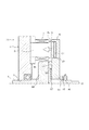
図11は本発明の第4実施例になるアキシャルギャップ型回転電機の構造を概略示す縦断面図である。図11は接合面半径が小さい状態(=R1)を表す。この第4実施例の基本構成は、上述した第1実施例と共通するため、同一部材については、共通する符号を付して説明を省略し、異なる構成について説明する。 FIG. 11 is a longitudinal sectional view schematically showing the structure of an axial gap type rotating electrical machine according to the fourth embodiment of the present invention. FIG. 11 shows a state where the radius of the joint surface is small (= R1). Since the basic configuration of the fourth embodiment is the same as that of the first embodiment described above, the same members will be denoted by the same reference numerals and description thereof will be omitted, and different configurations will be described.
第4実施例のアキシャルギャップ型回転電機41は、出力軸大径部4dの軸線Oに直角な端面が、ロータ6前面に直接に接合する。これにより、ロータ6の軸線O方向の動きをガタツキ無く規制する。ロータ6前面は、図11に示すように、軸中心部でテーパに形成される。
In the axial gap type rotating
吸引力(電磁力)が図11に示す場合よりも大きいとき、電磁力の軸線O方向成分がロータ6を引き寄せる。そうするとスラストによりテーパ6前面が変形し、テーパが少なくなるとともに大径部4dとロータ6との接合面の半径が大きくなる。
When the attractive force (electromagnetic force) is larger than that shown in FIG. 11, the component of the electromagnetic force in the direction of the axis O attracts the
このように電磁力の軸線O方向成分によって出力軸4とロータ6との接合面の半径を変化させて、ロータ6が面振動により共振する固有振動数を変化させる。これにより、ロータ6の面振動の共振を防止することができ、静粛な運転が可能になる。
In this way, the radius of the joint surface between the
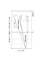
上述した第1〜第4実施例のアキシャルギャップ型回転電機11,21,31,41はいずれも吸引力になる電磁力の軸線O方向成分によって出力軸4とロータ6との接合面の半径を変化させる。この電磁力の制御は、図12に示す交流電流と吸引力との関係を表した特性図に基づく。
In the axial gap type rotating
図12中、横軸は電機子巻線7を流れる相電流の実効値(または最大値)であり、縦軸は、ステータ1とロータ6との間に発生する電磁力の軸線O方向成分になる吸引力である。また、図12中には、電流位相角βが−90度(強め界磁)のときを破線で示す。また、電流位相角βが0度のときを実線で示す。また、電流位相角βが+90度(弱め界磁)のときを一点鎖線で示す。
通常は、相電流をIa以下にしてアキシャルギャップ型回転電機11,21,31,41を駆動運転する。また電流位相角βの極性を+側にする弱め界磁制御を行う。このため、吸引力を弱める側になる。したがって通常運転における駆動時使用領域は、図12に示すようにβ=0度の線と、電機位相角β=+90度の線と、相電流=Iaの線で包囲されたを示す。
In FIG. 12, the horizontal axis represents the effective value (or maximum value) of the phase current flowing through the armature winding 7, and the vertical axis represents the axial O direction component of the electromagnetic force generated between the
Normally, the axial gap rotating
上述した通常運転における駆動時使用領域に対し、ロータ固有振動数を前述した図4および図8のように変化させてロータ回転速度から離隔するときは、相電流をIa以上にしてアキシャルギャップ型回転電機11,21,31,41を駆動運転する。また電流位相角βの極性を−側にする強め界磁制御を行う。このため、吸引力を強める側になる。図12には、実線の楕円で示すように、固有振動数を回転速度から離隔する運転における固有値可変制御領域を示す。
When the rotor natural frequency is changed as shown in FIG. 4 and FIG. 8 as described above with respect to the above-mentioned operating range in the normal operation, the axial current is rotated by setting the phase current to Ia or more. The
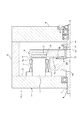
ここで弱め界磁制御および強め界磁制御につき、図13に沿って説明する。図13は、ステータ鉄心5と、磁石10との周方向相対位置関係を模式的に示す周方向展開図であって、電流位相角βが0のときを示す。図13において、電流位相角βの極性を−側にすると先端5sがN極であるステータ鉄心5に、前面がS極の永久磁石10bが近づくこととなり、吸引力が強くなることが理解されよう。
Here, the weak field control and the strong field control will be described with reference to FIG. FIG. 13 is a circumferential development diagram schematically showing the circumferential relative positional relationship between the
図14および図15は本発明の第5実施例になるアキシャルギャップ型回転電機の構造を概略示す縦断面図である。図14は接合面半径が大きい状態(=R3)を表す。図15は接合面半径が図14の状態より小さい状態(=R1)を表す。この第5実施例の基本構成は、上述した第1実施例と共通するため、同一部材については、共通する符号を付して説明を省略し、異なる構成について説明する。 14 and 15 are longitudinal sectional views schematically showing the structure of an axial gap type rotating electrical machine according to a fifth embodiment of the present invention. FIG. 14 shows a state (= R3) where the radius of the joint surface is large. FIG. 15 shows a state (= R1) where the radius of the joint surface is smaller than the state of FIG. Since the basic configuration of the fifth embodiment is the same as that of the first embodiment described above, the same members are denoted by the same reference numerals, description thereof is omitted, and different configurations are described.
第5実施例のアキシャルギャップ型回転電機51は、ロータ6と出力軸4との接合面積を変化させるアクチュエータを具える。このアクチュエータは、ロータ6を軸線方向に変位させるピストン機構である。
The axial gap type rotating
環状の皿ばね52に出力軸4を貫通し、この皿ばね52をロータ6背面に配設する。カラー14は皿ばね52が軸線O方向に抜け出ることを防止する。皿ばね52はロータ6を出力軸大径部4d側に押圧し、図14に示すようにロータ6を出力軸大径部4dに接合する。
The
出力軸大径部4dには、軸線O方向に摺動するピストン53と、ピストン53を収納するシリンダ54を設ける。シリンダ54は、出力軸4内部に設けた油圧配管55と接続する。ロータ6が大径部4dに半径R3で接合する間、図14に示すようにピストン53は完全にシリンダ54に収納されている。
The output shaft large-
油圧配管55からシリンダ54に油圧を供給して、ピストン53を大径部4dの環状端面4tから突出させてロータ6を皿ばね52側に変位させると、図15に示すように、ロータ6と出力軸大径部4dとの接合面半径がR1と小さくなる。
なお、シリンダ54の油圧を低下させると、皿ばね52の押圧力によってピストン53は環状端面4tまで後退する。このようにシリンダ54の油圧を変化させることにより、接合面半径をR1またはR4に任意に変化させることができる。
When hydraulic pressure is supplied from the
When the hydraulic pressure of the
以上の説明から明らかなように第5実施例では、図16の特性図に示すように、接合面半径がR3のとき面振動により共振する固有振動数(回転速度)はfR3である。接合面半径がR1のとき面振動により共振する固有振動数(回転速度)はfR1である。ロータ6と出力軸4との接合半径がR3と大きければ、ロータ6の支持剛性が高いため、図16に示すように、固有振動数fR3が固有振動数fR1より大きくなる。固有振動数を図16の矢に示すように小さくするには、シリンダ54に油圧を供給して接合面半径をR3からR1に小さくする。
As is apparent from the above description, in the fifth embodiment, as shown in the characteristic diagram of FIG. 16, when the joint surface radius is R3, the natural frequency (rotational speed) that resonates due to surface vibration is fR3 . When the joint surface radius is R1, the natural frequency (rotational speed) that resonates by surface vibration is f R1 . If the joint radius between the
また第5実施例のアキシャルギャップ型回転電機51では、ピストン機構を用いてロータ6の軸線O方向に変位させることから、第1〜第4実施例のアキシャルギャップ型回転電機よりも、遥かにロータ6の軸線O方向変位量を大きくすることができ、エアギャップ9を大きくすることができる。したがって、ロータ回転速度が所定値よりも大きい場合には、エアギャップ9を大きくしてモータとしての高速回転に不利益となる誘起電圧を低下させることができる。
Further, in the axial gap type rotating
これまで説明して来た第1〜第5実施例のアキシャルギャップ型回転電機11,21,31,41,51はロータを1個具える構造であったが、以下に説明するようにロータを2個具えた2ロータ1ステータ構造のアキシャルギャップ型回転電機であっても、ロータと出力軸との結合状態を変化させて、ロータが面振動により共振する固有振動数をロータの回転速度から離隔することが可能である。
The axial gap type rotating
図17は本発明の第6実施例になるアキシャルギャップ型回転電機の構造を概略示す縦断面図であり、接合面半径が小さい状態(=R1)を表す。この第6実施例の基本構成は、上述した第1実施例と共通し、ステータ1からみてロータ6を左右対称に配置したものである。
FIG. 17 is a longitudinal sectional view schematically showing the structure of an axial gap type rotating electrical machine according to the sixth embodiment of the present invention, and shows a state (= R1) where the radius of the joint surface is small. The basic configuration of the sixth embodiment is the same as that of the first embodiment described above, and the
図18は本発明の第7実施例になるアキシャルギャップ型回転電機の構造を概略示す縦断面図であり、接合面半径が大きい状態(=R3)を表す。この第7実施例の基本構成は、上述した第5実施例と共通し、ステータ1からみてロータ6を左右対称に配置したものである。
FIG. 18 is a longitudinal sectional view schematically showing the structure of an axial gap type rotating electrical machine according to the seventh embodiment of the present invention, and shows a state (= R3) where the joint surface radius is large. The basic configuration of the seventh embodiment is the same as that of the fifth embodiment described above, and the
なお、上述したのはあくまでも本発明の一実施例であり、本発明はその主旨に逸脱しない範囲において種々変更が加えられうるものである。 The above description is merely an example of the present invention, and the present invention can be variously modified without departing from the spirit of the present invention.
1 回転電機のステータ
2 ステータコア
4 出力軸
5 ステータ鉄心
6 回転電機のロータ
7 電機子巻線
8 モータケース
9 エアギャップ
10 ロータ永久磁石
12 バックヨーク
13 ストッパ
14 カラー
15 菊ワッシャ
16 ロックナット
23,33 ストッパ
52 皿ばね
53 ピストン
54 シリンダ
55 油圧配管
DESCRIPTION OF
Claims (12)
前記ロータと該ロータに結合する出力軸との結合状態を変化させることにより、前記ロータが面振動により共振する固有振動数を前記ロータの回転速度から離隔するよう構成したことを特徴とするアキシャルギャップ型回転電機。 In an axial gap type rotating electrical machine in which a stator and a disk-shaped rotor are arranged opposite to each other in the axial direction, and the rotor is driven by electromagnetic force generated between the stator and the rotor,
An axial gap characterized in that, by changing a coupling state between the rotor and an output shaft coupled to the rotor, the natural frequency at which the rotor resonates due to surface vibration is separated from the rotational speed of the rotor. Type rotating electric machine.
前記電磁力の軸線方向成分によって前記結合状態を変化させることを特徴とするアキシャルギャップ型回転電機。 In the axial gap type rotating electrical machine according to claim 1,
The axial gap type rotating electric machine characterized in that the coupling state is changed by an axial component of the electromagnetic force.
前記ロータと前記出力軸とが接合する接合面の半径を変化させることにより、前記結合状態を変化させることを特徴とするアキシャルギャップ型回転電機。 In the axial gap type rotating electrical machine according to claim 2,
The axial gap type rotating electrical machine characterized in that the coupling state is changed by changing a radius of a joint surface where the rotor and the output shaft are joined.
前記接合面が、軸線方向に突出したテーパと該テーパを受け止める面の組合せであることを特徴とするアキシャルギャップ型回転電機。 In the axial gap type rotating electrical machine according to claim 3,
The axial gap type rotating electrical machine, wherein the joint surface is a combination of a taper protruding in the axial direction and a surface receiving the taper.
前記接合面が、軸線方向に突出した曲面と該曲面を受け止める面の組合せであることを特徴とするアキシャルギャップ型回転電機。 In the axial gap type rotating electrical machine according to claim 3,
An axial gap type rotating electrical machine, wherein the joint surface is a combination of a curved surface protruding in the axial direction and a surface for receiving the curved surface.
前記接合面に前記ロータの軸線方向位置を規定するストッパを介挿し、該ストッパは前記電磁力の軸線方向成分によって変形しながら前記接合面の半径を変化させることを特徴とするアキシャルギャップ型回転電機。 In the axial gap type rotating electrical machine according to any one of claims 3 to 5,
An axial gap type rotating electrical machine characterized in that a stopper defining the axial position of the rotor is inserted in the joint surface, and the stopper changes the radius of the joint surface while being deformed by an axial component of the electromagnetic force. .
前記接合面は軸線方向に直角な環状であって、該環状接合面をなすロータ側部材または出力軸側部材のうち一方側部材の環状接合面内径側に前記ストッパを取り付け、
前記環状接合面外径側になる前記一方側部材の端面を前記ストッパよりも高剛性の部材で形成し、
前記ストッパを前記一方側部材の端面よりも軸線方向に突出させて他方側部材に接合し、
前記ストッパの変形により前記一方側部材の端面が他方側部材に接合することを特徴とするアキシャルギャップ型回転電機。 In the axial gap type rotating electrical machine according to claim 6,
The joint surface is an annular shape perpendicular to the axial direction, and the stopper is attached to the inner diameter side of the annular joint surface of one side member of the rotor side member or the output shaft side member forming the annular joint surface,
The end surface of the one side member that becomes the outer diameter side of the annular joint surface is formed of a member having higher rigidity than the stopper,
The stopper is protruded in the axial direction from the end surface of the one side member and joined to the other side member,
An axial gap type rotating electrical machine, wherein an end face of the one side member is joined to the other side member by deformation of the stopper.
前記ロータと前記出力軸とを相互に押圧させて接合し、
前記ロータと前記出力軸との間に前記押圧力を変化させるアクチュエータを設け、
該アクチュエータが前記ロータと前記出力軸との接合半径を変化させることにより、前
記結合状態を変化させることを特徴とするアキシャルギャップ型回転電機。 In the axial gap type rotating electrical machine according to claim 1,
The rotor and the output shaft are pressed against each other and joined together,
An actuator for changing the pressing force between the rotor and the output shaft;
An axial gap type rotating electrical machine characterized in that the coupling state is changed by the actuator changing a joint radius between the rotor and the output shaft.
前記アクチュエータは、前記ロータを軸線方向に変位させるピストン機構であることを特徴とするアキシャルギャップ型回転電機。 In the axial gap type rotating electrical machine according to claim 8,
The axial gap type rotating electric machine, wherein the actuator is a piston mechanism that displaces the rotor in an axial direction.
前記ピストン機構は、前記出力軸の回転速度が所定値より大きい場合に、前記ロータと前記ステータとのエアギャップを大きくすることを特徴とするアキシャルギャップ型回転電機。 In the axial gap type rotating electrical machine according to claim 9,
The axial gap type rotating electrical machine characterized in that the piston mechanism increases an air gap between the rotor and the stator when the rotational speed of the output shaft is larger than a predetermined value.
前記電機子巻線の電流値および電流位相角によって前記電磁力の軸線方向成分を制御する手段を設けたことを特徴とするアキシャルギャップ型回転電機。 The axial gap type rotating electric machine according to claim 2, wherein an armature winding is provided in the stator, a permanent magnet is provided in the rotor, and the rotor is driven at a synchronous speed with a field of the armature winding.
An axial gap type rotating electrical machine comprising means for controlling an axial component of the electromagnetic force according to a current value and a current phase angle of the armature winding.
前記電磁力の軸線方向成分は、前記ステータと前記ロータとの間の吸引力であって、
前記手段は、前記出力軸の目標出力トルクを達成する前記電流位相角の極性を、前記吸引力を強める側にすることを特徴とするアキシャルギャップ型回転電機。 In the axial gap type rotating electrical machine according to claim 11,
The axial component of the electromagnetic force is an attractive force between the stator and the rotor,
The axial gap type rotating electrical machine is characterized in that the means sets the polarity of the current phase angle that achieves the target output torque of the output shaft to a side that increases the attractive force.
Priority Applications (5)
| Application Number | Priority Date | Filing Date | Title |
|---|---|---|---|
| JP2007239268A JP5061806B2 (en) | 2007-09-14 | 2007-09-14 | Axial gap type rotating electrical machine |
| CN2008102153862A CN101388588B (en) | 2007-09-14 | 2008-09-11 | Axial gap-type electric motor |
| US12/208,911 US7948132B2 (en) | 2007-09-14 | 2008-09-11 | Axial gap-type electric motor |
| KR1020080090100A KR101000188B1 (en) | 2007-09-14 | 2008-09-12 | Axial Gap-type Rotary Electric Machine |
| EP08164315.7A EP2037557B1 (en) | 2007-09-14 | 2008-09-15 | Axial gap-type electric motor |
Applications Claiming Priority (1)
| Application Number | Priority Date | Filing Date | Title |
|---|---|---|---|
| JP2007239268A JP5061806B2 (en) | 2007-09-14 | 2007-09-14 | Axial gap type rotating electrical machine |
Publications (2)
| Publication Number | Publication Date |
|---|---|
| JP2009072012A true JP2009072012A (en) | 2009-04-02 |
| JP5061806B2 JP5061806B2 (en) | 2012-10-31 |
Family
ID=39816779
Family Applications (1)
| Application Number | Title | Priority Date | Filing Date |
|---|---|---|---|
| JP2007239268A Expired - Fee Related JP5061806B2 (en) | 2007-09-14 | 2007-09-14 | Axial gap type rotating electrical machine |
Country Status (5)
| Country | Link |
|---|---|
| US (1) | US7948132B2 (en) |
| EP (1) | EP2037557B1 (en) |
| JP (1) | JP5061806B2 (en) |
| KR (1) | KR101000188B1 (en) |
| CN (1) | CN101388588B (en) |
Cited By (1)
| Publication number | Priority date | Publication date | Assignee | Title |
|---|---|---|---|---|
| CN102889970A (en) * | 2012-10-22 | 2013-01-23 | 中国船舶重工集团公司第七0四研究所 | Test method capable of realizing vibration characteristics physical separation of stator and rotor |
Families Citing this family (13)
| Publication number | Priority date | Publication date | Assignee | Title |
|---|---|---|---|---|
| KR102299449B1 (en) * | 2014-10-06 | 2021-09-08 | 현대모비스 주식회사 | Motor rotor assembly axial flux permanent magnet motor |
| JP6867734B2 (en) * | 2016-08-03 | 2021-05-12 | 株式会社トプコン | Shaft support structure, laser beam irradiation unit and surveying device |
| JP6862906B2 (en) * | 2017-02-24 | 2021-04-21 | 株式会社デンソー | Shift range controller |
| US11005322B2 (en) | 2017-06-05 | 2021-05-11 | E-Circuit Motors, Inc. | Rotor assemblies for axial flux machines |
| GB2583974B (en) * | 2019-05-17 | 2023-12-06 | Time To Act Ltd | Improvements to the construction of axial flux rotary generators |
| KR20220100001A (en) * | 2019-11-12 | 2022-07-14 | 이-서킷 모터스 인코퍼레이티드 | Improved rotor assembly for axial flux machines |
| WO2021212134A1 (en) * | 2020-04-14 | 2021-10-21 | Monteith Robert Lothar | Fluid turbine rotor blade |
| GB2595492B (en) * | 2020-05-28 | 2022-08-17 | Yasa Ltd | A controller for an axial flux machine and method |
| JP2024506380A (en) | 2021-02-17 | 2024-02-13 | イー-サーキット モーターズ, インコーポレイテッド | Planar stator configuration for axial flux machines |
| CN113489187B (en) * | 2021-07-08 | 2022-09-02 | 珠海格力电器股份有限公司 | Vibration reduction rotor and motor with same |
| AU2022318884A1 (en) | 2021-07-30 | 2024-01-25 | E-Circuit Motors, Inc. | Magnetic material filled printed circuit boards and printed circuit board stators |
| US11336130B1 (en) | 2021-08-17 | 2022-05-17 | E-Circuit Motors, Inc. | Low-loss planar winding configurations for an axial flux machine |
| DE102021121909B3 (en) * | 2021-08-24 | 2023-01-19 | Schaeffler Technologies AG & Co. KG | Rotor unit of an electric axial flow machine and electric axial flow machine |
Citations (9)
| Publication number | Priority date | Publication date | Assignee | Title |
|---|---|---|---|---|
| JPS63262053A (en) * | 1987-04-15 | 1988-10-28 | Sony Corp | Motor |
| JPH11225464A (en) * | 1998-02-06 | 1999-08-17 | Matsushita Electric Ind Co Ltd | Motor, torque generation device, vacuum cleaner, electric fan and motor car |
| WO2005008865A1 (en) * | 2003-07-18 | 2005-01-27 | Yamaha Hatsudoki Kabushiki Kaisha | Motor generator and electric vehicle having the same |
| JP2005261169A (en) * | 2004-03-15 | 2005-09-22 | Tokyo Univ Of Science | Bearing-less motor and rotor therefor |
| JP2005287212A (en) * | 2004-03-30 | 2005-10-13 | Nissan Motor Co Ltd | Stator teeth structure of axial gap rotary electric machine |
| JP2006050709A (en) * | 2004-08-02 | 2006-02-16 | Matsushita Electric Ind Co Ltd | Electric power steering device |
| WO2006049114A1 (en) * | 2004-11-02 | 2006-05-11 | Matsushita Electric Industrial Co., Ltd. | Thrust dynamic pressure bearing, spindle motor using the bearing, and information recording/reproducing device using the spindle motor |
| JP2006158035A (en) * | 2004-11-26 | 2006-06-15 | Matsushita Electric Ind Co Ltd | Dc brushless motor |
| JP2006353078A (en) * | 2005-05-17 | 2006-12-28 | Nissan Motor Co Ltd | Axial-gap rotary electric machine |
Family Cites Families (10)
| Publication number | Priority date | Publication date | Assignee | Title |
|---|---|---|---|---|
| GB1218056A (en) * | 1968-10-09 | 1971-01-06 | Edward Stanley Beyers | Improvements in alternators |
| JPS5932983B2 (en) * | 1978-09-01 | 1984-08-13 | 株式会社日立製作所 | Rotor of magnet generator and its manufacturing method |
| US5110257A (en) | 1988-05-12 | 1992-05-05 | United Technologies Corporation | Apparatus for supporting a rotating shaft in a rotary machine |
| JP3241947B2 (en) | 1994-10-06 | 2001-12-25 | 株式会社東芝 | Rotating electric machine |
| CN1153334C (en) * | 2000-06-29 | 2004-06-09 | 台达电子工业股份有限公司 | Thin motor |
| GB2370320A (en) * | 2000-12-21 | 2002-06-26 | Ingersoll Rand Europ Sales Ltd | Compressor and driving motor assembly |
| EP1666763B1 (en) | 2003-09-10 | 2012-10-31 | Sintokogio, Ltd. | Device and method for damping vibration of rotating shaft system |
| DE102004045626A1 (en) * | 2004-09-21 | 2006-04-06 | Robert Bosch Gmbh | Electric machine |
| JP2007239268A (en) | 2006-03-07 | 2007-09-20 | Daiwa House Ind Co Ltd | Structure of vibration control wall |
| DE202007007217U1 (en) * | 2007-05-18 | 2007-08-02 | Yeh, Don-Lon | Brushless motor for e.g. electric vehicle, has connector that is tilted such that rotor is drawn from connector so that air gap is changed, and spring unit pressing rotor in direction opposite to stator so that connector is stretched |
-
2007
- 2007-09-14 JP JP2007239268A patent/JP5061806B2/en not_active Expired - Fee Related
-
2008
- 2008-09-11 CN CN2008102153862A patent/CN101388588B/en not_active Expired - Fee Related
- 2008-09-11 US US12/208,911 patent/US7948132B2/en not_active Expired - Fee Related
- 2008-09-12 KR KR1020080090100A patent/KR101000188B1/en active IP Right Grant
- 2008-09-15 EP EP08164315.7A patent/EP2037557B1/en not_active Expired - Fee Related
Patent Citations (9)
| Publication number | Priority date | Publication date | Assignee | Title |
|---|---|---|---|---|
| JPS63262053A (en) * | 1987-04-15 | 1988-10-28 | Sony Corp | Motor |
| JPH11225464A (en) * | 1998-02-06 | 1999-08-17 | Matsushita Electric Ind Co Ltd | Motor, torque generation device, vacuum cleaner, electric fan and motor car |
| WO2005008865A1 (en) * | 2003-07-18 | 2005-01-27 | Yamaha Hatsudoki Kabushiki Kaisha | Motor generator and electric vehicle having the same |
| JP2005261169A (en) * | 2004-03-15 | 2005-09-22 | Tokyo Univ Of Science | Bearing-less motor and rotor therefor |
| JP2005287212A (en) * | 2004-03-30 | 2005-10-13 | Nissan Motor Co Ltd | Stator teeth structure of axial gap rotary electric machine |
| JP2006050709A (en) * | 2004-08-02 | 2006-02-16 | Matsushita Electric Ind Co Ltd | Electric power steering device |
| WO2006049114A1 (en) * | 2004-11-02 | 2006-05-11 | Matsushita Electric Industrial Co., Ltd. | Thrust dynamic pressure bearing, spindle motor using the bearing, and information recording/reproducing device using the spindle motor |
| JP2006158035A (en) * | 2004-11-26 | 2006-06-15 | Matsushita Electric Ind Co Ltd | Dc brushless motor |
| JP2006353078A (en) * | 2005-05-17 | 2006-12-28 | Nissan Motor Co Ltd | Axial-gap rotary electric machine |
Cited By (1)
| Publication number | Priority date | Publication date | Assignee | Title |
|---|---|---|---|---|
| CN102889970A (en) * | 2012-10-22 | 2013-01-23 | 中国船舶重工集团公司第七0四研究所 | Test method capable of realizing vibration characteristics physical separation of stator and rotor |
Also Published As
| Publication number | Publication date |
|---|---|
| CN101388588B (en) | 2011-09-14 |
| EP2037557A3 (en) | 2012-07-25 |
| KR101000188B1 (en) | 2010-12-10 |
| US7948132B2 (en) | 2011-05-24 |
| EP2037557A2 (en) | 2009-03-18 |
| CN101388588A (en) | 2009-03-18 |
| US20090072640A1 (en) | 2009-03-19 |
| KR20090028452A (en) | 2009-03-18 |
| EP2037557B1 (en) | 2014-03-19 |
| JP5061806B2 (en) | 2012-10-31 |
Similar Documents
| Publication | Publication Date | Title |
|---|---|---|
| JP5061806B2 (en) | Axial gap type rotating electrical machine | |
| JP4394115B2 (en) | Axial gap type motor | |
| JP4729551B2 (en) | Axial gap type motor | |
| JP2008271640A (en) | Axial gap motor | |
| JP2006304592A (en) | System for fixing permanent magnet | |
| JP2011080579A (en) | Clutch mechanism | |
| WO2013187050A1 (en) | Rotary electric machine | |
| JP6304124B2 (en) | Engagement system and brake system and clutch system using the same | |
| WO2020230507A1 (en) | Rotor and motor provided with same | |
| JP2010025318A (en) | Power transmission device | |
| JP2008043093A (en) | Generator | |
| JP5233196B2 (en) | Rotating electrical machine rotor | |
| KR20150030040A (en) | Stator core and motor including stator core | |
| JP2001069738A (en) | External circumference opposing type motor | |
| JP2008131742A (en) | Motor | |
| JP2018085886A (en) | Motor with double rotor structure | |
| JP2007244064A (en) | Motor | |
| JP5276473B2 (en) | Pulley structure | |
| JP2010233325A (en) | Brushless motor | |
| JP5124998B2 (en) | Rotating electric machine | |
| JP2009171687A (en) | Rotating electrical machine | |
| JP5017045B2 (en) | Axial gap type motor | |
| JP6035596B2 (en) | Electric motor rotor, electric motor and washing machine | |
| KR102390035B1 (en) | Flux Concentrate Type Motor | |
| JP2005269852A (en) | Brushless motor |
Legal Events
| Date | Code | Title | Description |
|---|---|---|---|
| A621 | Written request for application examination |
Free format text: JAPANESE INTERMEDIATE CODE: A621 Effective date: 20100827 |
|
| A521 | Written amendment |
Free format text: JAPANESE INTERMEDIATE CODE: A523 Effective date: 20100929 |
|
| RD03 | Notification of appointment of power of attorney |
Free format text: JAPANESE INTERMEDIATE CODE: A7423 Effective date: 20111122 |
|
| RD04 | Notification of resignation of power of attorney |
Free format text: JAPANESE INTERMEDIATE CODE: A7424 Effective date: 20120323 |
|
| A977 | Report on retrieval |
Free format text: JAPANESE INTERMEDIATE CODE: A971007 Effective date: 20120704 |
|
| TRDD | Decision of grant or rejection written | ||
| A01 | Written decision to grant a patent or to grant a registration (utility model) |
Free format text: JAPANESE INTERMEDIATE CODE: A01 Effective date: 20120710 |
|
| A01 | Written decision to grant a patent or to grant a registration (utility model) |
Free format text: JAPANESE INTERMEDIATE CODE: A01 |
|
| A61 | First payment of annual fees (during grant procedure) |
Free format text: JAPANESE INTERMEDIATE CODE: A61 Effective date: 20120723 |
|
| R150 | Certificate of patent or registration of utility model |
Ref document number: 5061806 Country of ref document: JP Free format text: JAPANESE INTERMEDIATE CODE: R150 Free format text: JAPANESE INTERMEDIATE CODE: R150 |
|
| FPAY | Renewal fee payment (event date is renewal date of database) |
Free format text: PAYMENT UNTIL: 20150817 Year of fee payment: 3 |
|
| RD04 | Notification of resignation of power of attorney |
Free format text: JAPANESE INTERMEDIATE CODE: A7424 Effective date: 20130213 |
|
| A072 | Dismissal of procedure [no reply to invitation to correct request for examination] |
Free format text: JAPANESE INTERMEDIATE CODE: A072 Effective date: 20130625 |
|
| LAPS | Cancellation because of no payment of annual fees |