JP2009071977A - Power relay apparatus and power supply unit - Google Patents
Power relay apparatus and power supply unit Download PDFInfo
- Publication number
- JP2009071977A JP2009071977A JP2007237712A JP2007237712A JP2009071977A JP 2009071977 A JP2009071977 A JP 2009071977A JP 2007237712 A JP2007237712 A JP 2007237712A JP 2007237712 A JP2007237712 A JP 2007237712A JP 2009071977 A JP2009071977 A JP 2009071977A
- Authority
- JP
- Japan
- Prior art keywords
- plugs
- power
- power supply
- outlet
- plug
- Prior art date
- Legal status (The legal status is an assumption and is not a legal conclusion. Google has not performed a legal analysis and makes no representation as to the accuracy of the status listed.)
- Pending
Links
Images


Abstract
Description
本発明は、コンセントに電力を供給する電力中継装置および電源ユニットに関する。 The present invention relates to a power relay device and a power supply unit that supply power to an outlet.
発電所から各家庭へ電力を供給する電力供給システムにおいて、屋内配線手前の電力系統に停電が生じ、屋内配線への電力供給が途絶えることがある。かかる状況では、早期の原因究明と屋内配線への電力供給の復旧が望まれる。こうして、停電の原因となった箇所の特定、および事故点の復旧あるいは電力供給システムからの切り離しが行われる。 In a power supply system that supplies power from a power plant to each home, a power failure may occur in the power system in front of the indoor wiring, and the power supply to the indoor wiring may be interrupted. In such a situation, early investigation of the cause and restoration of power supply to the indoor wiring are desired. In this way, the location that caused the power failure is identified and the accident point is recovered or disconnected from the power supply system.
この際、屋内配線への電力供給復活まである程度の時間がかかる場合があり、その場合非常用電源に繋ぎ換えて急場を凌ぐ場合がある。かかる電源の繋ぎ換えは、例えば分電盤付近で電力供給システムとの接続を切り離し、屋内配線側に外部電源である発電機(例えば、エンジン発電機)を接続することで実行される。こうして、停電した電力系統からの電力の代わりとなる電力を屋内配線に供給することが可能となる。 At this time, it may take some time until the power supply to the indoor wiring is restored, and in that case, it may be replaced with an emergency power supply to surpass the emergency. Such reconnection of power is performed, for example, by disconnecting the connection to the power supply system near the distribution board and connecting a generator (for example, an engine generator) as an external power source to the indoor wiring side. In this way, it is possible to supply power to the indoor wiring in place of power from the power system that has failed.
しかし、上述したエンジン発電機は、騒音や排気の問題があり、また、保護継電器における電気接続の切断および外部電源の接続が作業者の手作業で行われるので、手間がかかるばかりでなく、危険も伴う。また、エンジン発電機が電力供給可能な運転状態になるまで長い起動時間を必要とする。 However, the above-mentioned engine generator has problems of noise and exhaust, and since the disconnection of the electrical connection and the connection of the external power supply in the protective relay are performed manually by the operator, it is not only troublesome but also dangerous. Also accompanies. Further, a long start-up time is required until the engine generator is in an operating state in which power can be supplied.
一方、このような停電時に、電力の継続的な供給が必要な電気機器、例えば、冷蔵庫等は、コンセントへ接続していたプラグを、屋内配線とは独立して電力供給可能なポータブル電源等の外部電源に接続して動作することができる。かかる外部電源は、燃料電池や二次電池を利用したものがあり、燃料電池の例では水素を燃料として数百W以上の電力を発生することができる(例えば、特許文献1参照)。このようなポータブル電源等の外部電源は、上述したエンジン発電機のような騒音や排気の問題がないため、導入しやすいといった利点を有する。
屋内で外部電源を利用する上記の技術では、コンセントに接続可能なプラグを有する電気機器に電力を供給できるものの、例えば、照明器具といった、屋内配線から直接給電されたり、プラグの形状が相異する電気機器には電力を供給できないといった問題が生じる。また屋内の離れた場所で複数の電機機器を使用する場合、電気機器毎に配線を別途準備する必要があり、手間とコストを費やすこととなる。 In the above technology using an external power supply indoors, although electric power can be supplied to an electric device having a plug that can be connected to an outlet, for example, lighting is directly supplied from indoor wiring or the shape of the plug is different. There arises a problem that electric power cannot be supplied to electrical equipment. In addition, when using a plurality of electrical equipments in a remote place indoors, it is necessary to separately prepare wiring for each electrical equipment, and labor and cost are expended.
本発明者は、このような家庭内で利用される外部電源を利用して、屋内の電気機器全てに電力を供給するため、コンセントを通じて屋内配線に外部電源を接続する構成を見出し、本発明を完成するに至った。 The inventor has found a configuration in which an external power source is connected to indoor wiring through an outlet in order to supply power to all indoor electric devices using such an external power source used in the home. It came to be completed.
しかし、上記の外部電源は、プラグを挿入することに関してコンセントと互換性を有し、その電力出力端は、コンセント同様、メス形状となっている。従って、外部電源とコンセントとを結ぶ接続ケーブルは、両端がオスのプラグとなる。かかる構造では、一方のプラグを電源に接続すると、露出したオス形状の他方のプラグ端子に電圧が生じ、導電物への接触による短絡事故の発生や人身への感電の原因になりかねない。 However, the above external power source is compatible with an outlet with respect to insertion of a plug, and its power output end has a female shape like the outlet. Therefore, both ends of the connection cable connecting the external power source and the outlet are male plugs. In such a structure, when one plug is connected to a power source, a voltage is generated at the other exposed male plug terminal, which may cause a short circuit accident due to contact with a conductive material or an electric shock to a person.
また、コンセントの電力が電力系統側と確実に切断されていない状態で外部電源を接続すると、電力系統と外部電源との出力同士がぶつかってしまい短絡事故が発生する。 Further, if the external power supply is connected in a state where the power of the outlet is not reliably disconnected from the power system side, the outputs of the power system and the external power supply collide with each other, causing a short circuit accident.
本発明は、従来の電力供給システムが有する上記問題点に鑑みてなされたものであり、本発明の目的は、簡易な構成で容易かつ迅速に、かつ十分な安全対策の下、屋内配線への電力の供給を実行し、作業者の負荷軽減と安全性や信頼性の向上を図ることが可能な電力中継装置および電源ユニットを提供することである。 The present invention has been made in view of the above-described problems of conventional power supply systems, and the object of the present invention is to easily and quickly with a simple configuration, and to indoor wiring under sufficient safety measures. An object of the present invention is to provide a power relay device and a power supply unit that can supply power and reduce the load on workers and improve safety and reliability.
上記課題を解決するために、本発明のある観点によれば、コンセントに接続可能な2つのプラグと、2つのプラグが接続先にそれぞれ接続されていることを検知する2つの接続検知部と、2つのプラグのうち、少なくともコンセントに接続されるプラグに電圧が生じていることを検知する電源検知部と、2つのプラグがそれぞれ接続され、かつ、コンセントに電圧が生じていないとき、2つのプラグを導通する導通回路と、を備えることを特徴とする、電力中継装置が提供される。 In order to solve the above-described problem, according to one aspect of the present invention, two plugs connectable to an outlet, two connection detection units that detect that the two plugs are respectively connected to connection destinations, Among the two plugs, at least a power source detection unit that detects that a voltage is generated in the plug connected to the outlet, and two plugs when the two plugs are connected to each other and no voltage is generated in the outlet. A power relay device is provided.
2つのプラグが接続先にそれぞれ接続されていないときには2つのプラグを導通しない構成により、一方のプラグに電力が供給されたとしても他方の露出したプラグ端子に電圧は生じず、接続状況に拘わらず、他方のプラグを安全に取り扱うことができる。 When the two plugs are not connected to the connection destinations, the two plugs do not conduct, so that even if power is supplied to one plug, no voltage is generated at the other exposed plug terminal, regardless of the connection status. The other plug can be handled safely.
さらに、コンセント(家庭用コンセント)に電圧が生じているときにも2つのプラグを導通しない構成により、電力系統と外部電源との出力同士が短絡するといった問題を回避でき、外部電源からの屋内配線への電力供給をさらに安全に遂行することが可能となる。 Furthermore, the configuration in which the two plugs do not conduct even when voltage is generated at the outlet (household outlet) can avoid the problem of short-circuiting between the output of the power system and the external power supply, and indoor wiring from the external power supply It becomes possible to carry out the power supply to the vehicle more safely.
電源検知部は、さらに検知結果を報知してもよい。かかる構成により、電源検知部の検知結果を視覚または聴覚によって把握でき、外部電源をオンする前に、本来切断されるべき電源系統がまだ接続されていることを認識することができるので、短絡の可能性を未然に防ぐことができる。 The power detection unit may further notify the detection result. With this configuration, the detection result of the power supply detection unit can be grasped visually or audibly, and it can be recognized that the power supply system that should be disconnected is still connected before the external power supply is turned on. The possibility can be prevented in advance.
電源検知部は、2つのプラグにそれぞれ設けられ、導通回路は、2つのプラグに対して対称的に構成されていてもよい。上述したように2つのプラグは同形状を成しているので誤接続の可能性を拭えない。かかる導通回路を対称的に構成することで、接続方向を気にすることなく2つのプラグのいずれをコンセントに接続してもよくなり、より容易かつ迅速に当該電力中継装置を接続することが可能となる。また、コンセントの電圧の有無を調べる場合でも、いずれのプラグを挿入しようと、その挿入した側の電源検知部の検知結果を把握すればよいので、電力の接続状態を感覚的に認識することができる。さらに、対称的な回路構成により、当該電力中継装置の設計や製造も容易に行うことができる。 The power supply detection unit may be provided in each of the two plugs, and the conduction circuit may be configured symmetrically with respect to the two plugs. As described above, since the two plugs have the same shape, the possibility of erroneous connection cannot be wiped off. By constructing such a conduction circuit symmetrically, any of the two plugs may be connected to the outlet without worrying about the connection direction, and the power relay device can be connected more easily and quickly. It becomes. In addition, even when checking the presence or absence of the voltage at the outlet, no matter which plug is inserted, it is only necessary to grasp the detection result of the power supply detection unit on the side where the plug is inserted. it can. Further, the power relay device can be easily designed and manufactured by a symmetrical circuit configuration.
導通回路は、リレーを含んで構成され、一方のプラグの電圧のみが生じ、かつ、他方のプラグが接続されているとき、2つのプラグに接続されたリレーの接点を閉じ、以後は自己保持回路により接点の閉状態を維持してもよい。 The conduction circuit is configured to include a relay, and when only one plug voltage is generated and the other plug is connected, the contact of the relay connected to the two plugs is closed, and thereafter the self-holding circuit. Thus, the closed state of the contact may be maintained.
かかる構成により、一方のプラグの電圧のみが生じ、かつ、他方のプラグが接続されているという条件を通じて2つのプラグ間を接続することができ、また、2つのプラグ間の接続で一方のプラグの電圧のみが生じている状態が解除され上記の条件を満たさなくなったとしても、自己保持回路によってそのままリレーの閉状態を維持できる。 With such a configuration, it is possible to connect two plugs through a condition that only one plug voltage is generated and the other plug is connected. Even if the state where only the voltage is generated is canceled and the above condition is not satisfied, the closed state of the relay can be maintained as it is by the self-holding circuit.
電源検知部と導通回路との間に過電流を遮断するヒューズをさらに備えてもよい。電源検知部と導通回路とにより、いずれか一方の電圧が断たれていないとプラグ間は導通しない。しかし、一旦導通すると自己保持回路によりその導通状態が維持されるので、何らかの原因で、電力系統からの電力が復活してしまうと、出力同士がぶつかって短絡してしまう。かかるヒューズを設ける構成により、上記の短絡状態においても、不特定箇所の負荷が損害を被るのを防止できる。 You may further provide the fuse which interrupts | blocks an overcurrent between a power supply detection part and a conduction circuit. The plugs do not conduct unless one of the voltages is cut off by the power source detection unit and the conduction circuit. However, once conducting, the conducting state is maintained by the self-holding circuit, so if the power from the power system is restored for some reason, the outputs collide with each other and short circuit. By providing such a fuse, it is possible to prevent the load at an unspecified location from being damaged even in the short-circuit state.
上記課題を解決するために、本発明の他の観点によれば、コンセントと独立して電力を生成可能な外部電源と、コンセントと外部電源とを中継する電力中継装置と、からなり、電力中継装置は、コンセントおよび外部電源に接続可能な2つのプラグと、2つのプラグがコンセントまたは外部電源にそれぞれ接続されていることを検知する2つの接続検知部と、2つのプラグのうち、少なくともコンセントに接続されるプラグに電圧が生じていることを検知する電源検知部と、2つのプラグがそれぞれ接続され、かつ、コンセントに電圧が生じていないとき、2つのプラグを導通する導通回路と、を備えることを特徴とする、電源ユニットが提供される。 In order to solve the above-described problem, according to another aspect of the present invention, an external power source capable of generating power independently of an outlet and a power relay device that relays the outlet and the external power source are provided. The apparatus includes two plugs connectable to an outlet and an external power source, two connection detection units for detecting that the two plugs are respectively connected to the outlet or the external power source, and at least one of the two plugs to the outlet. A power detection unit that detects that a voltage is generated in the plug to be connected; and a conduction circuit that conducts the two plugs when the two plugs are connected to each other and no voltage is generated in the outlet. A power supply unit is provided.
上述した、電力中継装置の技術的思想に基づく構成要素やその説明は、当該電源ユニットにも適用可能である。 The above-described components based on the technical idea of the power relay device and the description thereof are also applicable to the power supply unit.
以上説明したように本発明によれば、簡易な構成で容易かつ迅速に、かつ十分な安全対策の下、屋内配線への電力の供給を実行し、作業者の負荷軽減と安全性や信頼性の向上を図ることが可能となる。 As described above, according to the present invention, power supply to indoor wiring is executed easily and quickly with a simple configuration and with sufficient safety measures, and the load on the worker is reduced and safety and reliability are improved. Can be improved.
以下に添付図面を参照しながら、本発明の好適な実施の形態について詳細に説明する。なお、本明細書及び図面において、実質的に同一の機能構成を有する構成要素については、同一の符号を付することにより重複説明を省略する。 Exemplary embodiments of the present invention will be described below in detail with reference to the accompanying drawings. In addition, in this specification and drawing, about the component which has the substantially same function structure, duplication description is abbreviate | omitted by attaching | subjecting the same code | symbol.
発電所から各家庭へ電力を供給する電力供給システムにおいて、屋内配線手前の電力系統に停電が生じ、屋内配線への電力供給が途絶えた場合、必要に応じて、屋内配線への電力を早急に復活させるため、電力系統と屋内配線の分離を行い、その原因が屋内配線およびそれに接続された負荷ではないことを確認して、屋内配線に別途外部電源を接続する。 In a power supply system that supplies power to each household from the power plant, if a power failure occurs in the power system in front of the indoor wiring and the power supply to the indoor wiring is interrupted, the power to the indoor wiring is quickly In order to restore, separate the power system from the indoor wiring, confirm that the cause is not the indoor wiring and the load connected to it, and connect an external power supply to the indoor wiring separately.
図1は、このような屋内配線に外部電源を接続した場合の電気的な接続を示した説明図である。本実施形態における電力源の接続変更は、分電盤のサービスブレーカSBを開き、電力系統からの電力を切断した後、例えばポータブル電源等の外部電源110を、コンセント112(屋内配線)に接続することで実行される。こうして、停電した電力系統からの電力の代わりとなる電力を屋内配線に供給することが可能となる。
FIG. 1 is an explanatory diagram showing electrical connections when an external power source is connected to such indoor wiring. To change the connection of the power source in the present embodiment, the service breaker SB of the distribution board is opened, the power from the power system is disconnected, and then the
しかし、外部電源110をコンセントに単純に接続する構成では、感電や電源同士の短絡といった問題が生じる。本実施形態の電源ユニットまたは電力中継装置を電力供給システムに適用することで、このような感電や短絡といった問題点を解決する。ここでは、本実施形態の理解を容易にするため、まず、電源ユニットの全体的な構成について説明し、その後に電源ユニットの一部を構成する電力中継装置の具体的な構成について詳述する。
However, in the configuration in which the
(電源ユニット100)
図2は、電源ユニット100の外観図、図3は、電源ユニット100の概略的なブロック図を示す。電源ユニット100は、外部電源110と、電力中継装置120とを含んで構成される。
(Power supply unit 100)
FIG. 2 is an external view of the
上記外部電源110は、例えば、燃料電池や二次電池を利用して形成され、コンセント112からの電力、即ち電気系統から供給される電力と独立して、自己完結的に電力を生成することができる。なお外部電源110は燃料電池や二次電池以外にも、何らかの燃料を利用した発電機など、電力を発生する装置ならばどのようなものでもよい。
The
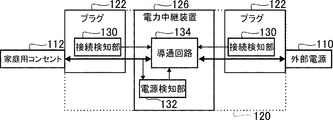
上記電力中継装置120は、コンセント112と外部電源110とを電気的に中継し、プラグ122と、ケーブル124と、本体126とからなる。
The
上記プラグ122は、コンセント112や外部電源110の電力出力端に接続でき、1つの電力中継装置120に少なくとも2つ設けられる。上記ケーブル124は、プラグ122から本体126までの電気的接続を行う。
The
上記本体126は、複数の電気素子を組み合わせて形成され、その電気素子を物理的に保護する筐体に覆われている。本体126は、その電気的機能を遂行する回路として、接続検知部130と、電源検知部132と、導通回路134とを含んでいる。
The
ここで、接続検知部130は、2つのプラグ122が接続先、ここでは、コンセント112および外部電源110にそれぞれ接続されていることを検知する。また、電源検知部132は、2つのプラグ122のうち、少なくともコンセント112に接続されるプラグ122に電圧が生じていることを検知する。そして、導通回路134は、2つのプラグ122がそれぞれ接続され、かつ、コンセント112に電圧が生じていないとき、この2つのプラグ122を導通する。かかる接続検知部130、電源検知部132、導通回路134の構成に関してそれぞれ詳細に説明する。
Here, the
(接続検知部130)
図4は、接続検知部130の一例を示した説明図である。かかる接続検知部130は、プラグ122に内蔵された物理的なスイッチによって構成される。そして、プラグ122をコンセント112または外部電源110に接続すると、プラグ122の接続側面140が接続先に当接し、突出部142が接続先に押圧される。接続検知部130は、突出部142に連動してスイッチ144が入る構成となっており、このスイッチ144の導通によって、コンセント112または外部電源110に確実に接続されたことを導通回路134に通知する。即ち、物理的なスイッチ144を通じて電気的に接続の有無を伝達している。
(Connection detection unit 130)
FIG. 4 is an explanatory diagram showing an example of the
ここでは、接続検知部130として物理的スイッチ144を用いているが、フォトインタラプタを用いてプラグ端子の挿入を検知したり、コンセント112とプラグ122との接触を磁気センサを用いて検知したり、プラグ122の接続により隔離された接点を接続し電気的に検知したり、様々な方法を用いて当該接続検知部130を構成することができる。
Here, although the
本実施形態では、接続検知部130を用いて、2つのプラグ122が接続先にそれぞれ接続されていないときには、この2つのプラグ122を導通しないこととしている。かかる構成により、一方のプラグ122に電力が供給されたとしても他方の露出したプラグ端子に電圧は生じず、接続状況に拘わらず、他方のプラグを安全に取り扱うことができる。
In the present embodiment, when the two
このような露出したプラグ端子を保護する方法として、例えば、付勢力により突出する保護カバーをプラグ端子の周囲に設け、コンセントへの挿入に連動してプラグ端子が露出する構成をとることもできる。しかし、かかる構成では、プラグ端子の一面が保護されているものの、他面は露出したままなので、プラグ端子への接触を完全に防止することができない。 As a method for protecting such an exposed plug terminal, for example, a protective cover protruding by an urging force may be provided around the plug terminal, and the plug terminal may be exposed in conjunction with insertion into the outlet. However, in such a configuration, although one surface of the plug terminal is protected, the other surface remains exposed, and thus contact with the plug terminal cannot be completely prevented.
(電源検知部132)
電源検知部132は、本実施形態のように外部電源110をコンセント112に接続する際に、電圧の有無を検知して、コンセント112にまだ電圧が生じていることを検知する。そして、コンセント112に電圧が生じていた場合、2つのプラグ122が接続先にそれぞれ接続されていないとき同様、2つのプラグ122を導通しない。
(Power supply detection unit 132)
When the
かかる構成により、電力系統と外部電源110との出力同士が短絡するといった問題を回避でき、外部電源110からの屋内配線への電力供給をさらに安全に遂行することが可能となる。
With this configuration, it is possible to avoid the problem that the outputs of the power system and the
また、電源検知部132は、検知結果をLED(Light Emitting Diode)、ランプ、液晶表示器、EL(Electro Luminescence)表示器やスピーカ、ベル等を用いて、視覚的または聴覚的に報知してもよい。
In addition, the
かかる構成により、電源検知部132の検知結果を視覚または聴覚によって把握でき、外部電源110をオンする前に、本来切断されるべき電源系統がまだ接続されていることを認識することができるので、短絡の可能性を未然に防ぐことができる。
With this configuration, the detection result of the
さらに、電源検知部132は、後に示す図5のように、2つのプラグ122にそれぞれ設けられ、後述する導通回路134は、2つのプラグ122に対して対称的に構成されていてもよい。上述したように2つのプラグ122は互いに同形状を成しているので誤接続の可能性を拭えない。
Furthermore, the
かかる電源検知部132および導通回路134を対称的に設けることで、接続方向を気にすることなく2つのプラグのいずれをコンセント112に接続してもよくなり、より容易かつ迅速に当該電力中継装置120を接続することが可能となる。また、コンセント112の電圧の有無を調べる場合でも、いずれのプラグ122を挿入しようと、その挿入した側の電源検知部132の検知結果をLED等の報知により把握すればよいので、電力の接続状態を感覚的に認識することができる。さらに、対称的な回路構成により、当該電力中継装置120の設計や製造も容易に行うことができる。
By providing the
(導通回路134)
上述したように、導通回路134は、2つのプラグが接続先にそれぞれ接続されているとき、かつ、コンセント112に電圧が生じていないときに2つのプラグ122を導通する。特に、電源検知部132および導通回路134を対称的に設ける構成では、2つのプラグが接続先にそれぞれ接続されているとき、かつ、いずれか一方しか電圧が生じていないときに2つのプラグ122を導通することとなる。
(Conduction circuit 134)
As described above, the
図5は、導通回路134の基本的な論理構成を説明するための説明図である。ここでは、接続検知部130がプラグ122の接続を検知したとき、および電源検知部132が電圧を検知したときをオン(1)としている。そして、2つの接続検知部130がオン、かつ、いずれかの電源検知部132がオンのときプラグ122の導通が図られる。また、図5中で、最終出力を論理和(OR)160にフィードバックしているのは、一旦、プラグ122が導通されると、2つの電源検知部132で電圧が検知され排他的論理和(XOR)162の出力を維持できなくなるので、出力のフィードバックでラッチをかけるためである。
FIG. 5 is an explanatory diagram for explaining a basic logical configuration of the
また、上記では、「いずれか一方しか電圧が生じていない」を条件としているが、どちらの電圧も生じていないときの導通回路134の状態は問われないので、かかる条件を「両電源からともに電圧が生じていない」に置き換えることができる。従って、図5の排他的論理和162を否定論理積(NAND)で構成することも可能である。
In the above, the condition is that only one of the voltages is generated. However, the state of the
このように、2つのプラグ122が接続先にそれぞれ接続されていないときには2つのプラグを導通しない構成により、プラグ122を安全に取り扱うことができ、さらに、両方のプラグ122に電圧が生じているときにも2つのプラグを導通しない構成により、電力系統と外部電源との出力同士の短絡を防止できる。従って、外部電源からの屋内配線への電力供給をさらに安全に遂行することが可能となる。
As described above, when the two
図6は、導通回路134の具体的な例を示す回路図である。ここでも、各プラグ122は、コンセント側と外部電源側とで対称的に回路が形成され、上述した論理判定を、リレー回路を用いて実行している。尚、図6で利用されるリレーQ1、Q2は、A接点(ノーマリーオープン)で構成され、リレーQ3、Q4は、B接点(ノーマリークローズ)で構成されている。
FIG. 6 is a circuit diagram showing a specific example of the
図6の外部電源側に着目すると、コンセント側の接続検知部130の接続検知と、コンセント側の電源検知部132のリレーQ4オフにより、外部電源側の導通回路134のリレーQ1は、外部電源110の供給を受けてオンになる。従って、接点180が閉じて2つのプラグ122が導通する。
Focusing on the external power supply side in FIG. 6, the relay Q1 of the
かかる導通により、コンセント側の接続検知部130であるリレーQ4がオンして接点182が開き、かかる接点182を経由していたリレーQ1への電力の供給が途絶える。しかし、最初にリレーQ1がオンになったときに接点180と共に自己保持用の接点184の接点も閉じているので、リレーQ1のオン状態は2つのプラグ122の導通後も維持される。
Due to this conduction, the relay Q4 which is the
また、図6のリレーQ1のオン条件には、本実施形態の導通条件である「2つのプラグ122が接続先にそれぞれ接続される」の一方(外部電源側)のプラグ122の接続が為されていないが、外部電源110の電圧が生じている条件が外部電源側プラグ122の接続条件を間接的に満たすので、図6のように、かかる一方のプラグ122の接続を省略することができる。
6 is connected to one (external power supply side) plug 122 of “the two
かかる構成により、一方のプラグ122の電圧のみが生じ、かつ、他方のプラグ122が接続されているという条件を通じて2つのプラグ間を接続することができ、また、2つのプラグ間の接続で一方のプラグ122の電圧のみが生じている状態が解除され上記の条件を満たさなくなったとしても、自己保持回路によってそのままリレーの閉状態を維持できる。
With such a configuration, only the voltage of one
また、電源検知部132と導通回路134との間に過電流を遮断するヒューズ190をさらに備えてもよい。電源検知部132と導通回路134とにより、いずれか一方の電力が断たれていないと2つのプラグ122は導通しない。しかし、一旦導通すると図5に示した自己保持回路によりその導通状態が維持されるので、何らかの原因で、電力系統からの電力が復活してしまうと、出力同士がぶつかって短絡してしまう。かかるヒューズ190を設ける構成により、上記の短絡状態においても、不特定箇所の負荷が損害を被るのを防止できる。
Further, a
ここで、ヒューズ190を電源側から見て電源検知部132の後段としたのは、ヒューズ190が前段だと電源検知部132が反応しなかったとき、その原因がヒューズ190にあるのか電源にあるのかの判別がつかないからである。
Here, when the
以上、添付図面を参照しながら本発明の好適な実施形態について説明したが、本発明は係る例に限定されないことは言うまでもない。当業者であれば、特許請求の範囲に記載された範疇内において、各種の変更例または修正例に想到し得ることは明らかであり、それらについても当然に本発明の技術的範囲に属するものと了解される。 As mentioned above, although preferred embodiment of this invention was described referring an accompanying drawing, it cannot be overemphasized that this invention is not limited to the example which concerns. It will be apparent to those skilled in the art that various changes and modifications can be made within the scope of the claims, and these are naturally within the technical scope of the present invention. Understood.
本発明は、コンセントに電力を供給する電力中継装置および電源ユニットに利用することができる。 The present invention can be used for a power relay device and a power supply unit that supply power to an outlet.
100 …電源ユニット
110 …外部電源
112 …コンセント
120 …電力中継装置
122 …プラグ
130 …接続検知部
132 …電源検知部
134 …導通回路
190 …ヒューズ
DESCRIPTION OF
Claims (6)
前記2つのプラグが接続先にそれぞれ接続されていることを検知する2つの接続検知部と、
前記2つのプラグのうち、少なくともコンセントに接続されるプラグに電圧が生じていることを検知する電源検知部と、
前記2つのプラグがそれぞれ接続され、かつ、コンセントに電圧が生じていないとき、該2つのプラグを導通する導通回路と、
を備えることを特徴とする、電力中継装置。 Two plugs that can be connected to an outlet,
Two connection detectors for detecting that the two plugs are respectively connected to connection destinations;
Of the two plugs, a power detection unit that detects that a voltage is generated in at least a plug connected to an outlet; and
A conduction circuit for conducting the two plugs when the two plugs are connected to each other and no voltage is generated at the outlet;
A power relay device comprising:
前記導通回路は、前記2つのプラグに対して対称的に構成されることを特徴とする、請求項1または2に記載の電力中継装置。 The power detection unit is provided in each of the two plugs,
The power relay apparatus according to claim 1, wherein the conduction circuit is configured symmetrically with respect to the two plugs.
前記コンセントと前記外部電源とを中継する電力中継装置と、
からなり、
前記電力中継装置は、
前記コンセントおよび外部電源に接続可能な2つのプラグと、
前記2つのプラグが前記コンセントまたは外部電源にそれぞれ接続されていることを検知する2つの接続検知部と、
前記2つのプラグのうち、少なくともコンセントに接続されるプラグに電圧が生じていることを検知する電源検知部と、
前記2つのプラグがそれぞれ接続され、かつ、コンセントに電圧が生じていないとき、該2つのプラグを導通する導通回路と、
を備えることを特徴とする、電源ユニット。 An external power supply that can generate power independently from the outlet;
A power relay device that relays between the outlet and the external power source;
Consists of
The power relay device is
Two plugs connectable to the outlet and an external power source;
Two connection detectors for detecting that the two plugs are respectively connected to the outlet or an external power source;
Of the two plugs, a power detection unit that detects that a voltage is generated in at least a plug connected to an outlet; and
A conduction circuit for conducting the two plugs when the two plugs are connected to each other and no voltage is generated at the outlet;
A power supply unit comprising:
Priority Applications (1)
| Application Number | Priority Date | Filing Date | Title |
|---|---|---|---|
| JP2007237712A JP2009071977A (en) | 2007-09-13 | 2007-09-13 | Power relay apparatus and power supply unit |
Applications Claiming Priority (1)
| Application Number | Priority Date | Filing Date | Title |
|---|---|---|---|
| JP2007237712A JP2009071977A (en) | 2007-09-13 | 2007-09-13 | Power relay apparatus and power supply unit |
Publications (1)
| Publication Number | Publication Date |
|---|---|
| JP2009071977A true JP2009071977A (en) | 2009-04-02 |
Family
ID=40607660
Family Applications (1)
| Application Number | Title | Priority Date | Filing Date |
|---|---|---|---|
| JP2007237712A Pending JP2009071977A (en) | 2007-09-13 | 2007-09-13 | Power relay apparatus and power supply unit |
Country Status (1)
| Country | Link |
|---|---|
| JP (1) | JP2009071977A (en) |
Cited By (7)
| Publication number | Priority date | Publication date | Assignee | Title |
|---|---|---|---|---|
| JP2011075536A (en) * | 2009-09-03 | 2011-04-14 | Tokai Rika Co Ltd | Current detecting device |
| JP2011101472A (en) * | 2009-11-04 | 2011-05-19 | Panasonic Electric Works Co Ltd | Dc distribution system |
| WO2014110543A1 (en) * | 2013-01-14 | 2014-07-17 | James Shanley | Backup power device, system and method of use |
| JP2015080407A (en) * | 2014-11-10 | 2015-04-23 | 株式会社シンワサービス | Accessory device of hybrid electric power generator |
| JP2015136199A (en) * | 2014-01-16 | 2015-07-27 | 日産自動車株式会社 | Power supply device, mobile body, and electricity distribution system |
| JP2021100328A (en) * | 2019-12-20 | 2021-07-01 | パナソニックIpマネジメント株式会社 | Power relay device, power supply system, and power distribution system |
| JP2021100365A (en) * | 2019-12-20 | 2021-07-01 | パナソニックIpマネジメント株式会社 | Power relay device, power supply system, and power distribution system |
Citations (5)
| Publication number | Priority date | Publication date | Assignee | Title |
|---|---|---|---|---|
| JPH02262849A (en) * | 1989-01-26 | 1990-10-25 | Fuji Electric Co Ltd | Power supply |
| US5118301A (en) * | 1991-05-02 | 1992-06-02 | Valentino Bentivolio | Electrical connector device |
| US6328597B1 (en) * | 2000-04-05 | 2001-12-11 | Oliver W. Epps | Electrical power and disabling jack |
| US20060079111A1 (en) * | 2003-04-18 | 2006-04-13 | Georgianna Reid | Double male two-prong electrical connector apparatus |
| US7227282B1 (en) * | 2003-08-05 | 2007-06-05 | Baucum Jr William E | Alternative alternating current power supply |
-
2007
- 2007-09-13 JP JP2007237712A patent/JP2009071977A/en active Pending
Patent Citations (5)
| Publication number | Priority date | Publication date | Assignee | Title |
|---|---|---|---|---|
| JPH02262849A (en) * | 1989-01-26 | 1990-10-25 | Fuji Electric Co Ltd | Power supply |
| US5118301A (en) * | 1991-05-02 | 1992-06-02 | Valentino Bentivolio | Electrical connector device |
| US6328597B1 (en) * | 2000-04-05 | 2001-12-11 | Oliver W. Epps | Electrical power and disabling jack |
| US20060079111A1 (en) * | 2003-04-18 | 2006-04-13 | Georgianna Reid | Double male two-prong electrical connector apparatus |
| US7227282B1 (en) * | 2003-08-05 | 2007-06-05 | Baucum Jr William E | Alternative alternating current power supply |
Cited By (10)
| Publication number | Priority date | Publication date | Assignee | Title |
|---|---|---|---|---|
| JP2011075536A (en) * | 2009-09-03 | 2011-04-14 | Tokai Rika Co Ltd | Current detecting device |
| JP2011101472A (en) * | 2009-11-04 | 2011-05-19 | Panasonic Electric Works Co Ltd | Dc distribution system |
| WO2014110543A1 (en) * | 2013-01-14 | 2014-07-17 | James Shanley | Backup power device, system and method of use |
| US9627926B2 (en) | 2013-01-14 | 2017-04-18 | James Shanley | Backup power device, system and method of use |
| JP2015136199A (en) * | 2014-01-16 | 2015-07-27 | 日産自動車株式会社 | Power supply device, mobile body, and electricity distribution system |
| JP2015080407A (en) * | 2014-11-10 | 2015-04-23 | 株式会社シンワサービス | Accessory device of hybrid electric power generator |
| JP2021100328A (en) * | 2019-12-20 | 2021-07-01 | パナソニックIpマネジメント株式会社 | Power relay device, power supply system, and power distribution system |
| JP2021100365A (en) * | 2019-12-20 | 2021-07-01 | パナソニックIpマネジメント株式会社 | Power relay device, power supply system, and power distribution system |
| JP7336668B2 (en) | 2019-12-20 | 2023-09-01 | パナソニックIpマネジメント株式会社 | Power repeater, power supply system and distribution system |
| JP7361315B2 (en) | 2019-12-20 | 2023-10-16 | パナソニックIpマネジメント株式会社 | Power relay equipment, power supply system and power distribution system |
Similar Documents
| Publication | Publication Date | Title |
|---|---|---|
| JP2009071977A (en) | Power relay apparatus and power supply unit | |
| US6746250B2 (en) | Connection for a distribution network | |
| JP6688804B2 (en) | DC circuit breaker and disconnector | |
| WO2021095280A1 (en) | Digital electric safety control system | |
| US8278573B2 (en) | Circuit breaker for use in high power system and the power system | |
| CN101924352A (en) | The safety switching apparatus that is used for solar facilities | |
| EP2498369A2 (en) | Control circuit for preventing battery group from being reversely connected and power supply system for base station | |
| US20140091763A1 (en) | Charging device for a high-voltage battery of a motor vehicle, charging assembly and method for operating a charging assembly | |
| CN109870647A (en) | A kind of monitoring system of breaker open operation electric loop failure | |
| US10388802B2 (en) | System and method for synchronized rapid shutdown of electrical devices | |
| GB2474245A (en) | Electrical safety device for electrical supply units | |
| CN106655898A (en) | Electric reactor cabinet control circuit | |
| US20060146464A1 (en) | Overvoltage protection device | |
| JP2018147835A (en) | Simulation breaker malfunction prevention device | |
| US9718526B2 (en) | Boat with high-voltage system | |
| KR102038635B1 (en) | Surge free auto reset earth leakage breaker | |
| US7187090B2 (en) | Mobile high voltage network | |
| JP6836233B1 (en) | Digital Electric Safety Control System | |
| JP2008193771A (en) | Bypass connection device for uninterruptible replacement of low voltage apparatus | |
| CN101286632B (en) | Device to send out alarming indication when abnormal voltage appearing in grounding system | |
| JP5934997B2 (en) | Power supply system | |
| CN100539344C (en) | When appearring in grounding system, can send abnormal voltage the device of the indication of reporting to the police | |
| JP2014054170A (en) | Power supply device in house | |
| KR102605217B1 (en) | Safe separating connector for photovoltaic power system | |
| JP2010277724A (en) | Power supply device |
Legal Events
| Date | Code | Title | Description |
|---|---|---|---|
| A621 | Written request for application examination |
Free format text: JAPANESE INTERMEDIATE CODE: A621 Effective date: 20100323 |
|
| A977 | Report on retrieval |
Free format text: JAPANESE INTERMEDIATE CODE: A971007 Effective date: 20110714 |
|
| A131 | Notification of reasons for refusal |
Free format text: JAPANESE INTERMEDIATE CODE: A131 Effective date: 20110809 |
|
| A02 | Decision of refusal |
Free format text: JAPANESE INTERMEDIATE CODE: A02 Effective date: 20111220 |